JP4345833B2 - Liquid ejection apparatus and liquid supply method - Google Patents
Liquid ejection apparatus and liquid supply methodDownload PDFInfo
- Publication number
- JP4345833B2 JP4345833B2JP2007072014AJP2007072014AJP4345833B2JP 4345833 B2JP4345833 B2JP 4345833B2JP 2007072014 AJP2007072014 AJP 2007072014AJP 2007072014 AJP2007072014 AJP 2007072014AJP 4345833 B2JP4345833 B2JP 4345833B2
- Authority
- JP
- Japan
- Prior art keywords
- liquid
- ink
- flow path
- pressure
- tube
- Prior art date
- Legal status (The legal status is an assumption and is not a legal conclusion. Google has not performed a legal analysis and makes no representation as to the accuracy of the status listed.)
- Expired - Fee Related
Links
- 239000007788liquidSubstances0.000titleclaimsdescription178
- 238000000034methodMethods0.000titleclaimsdescription6
- 230000014759maintenance of locationEffects0.000claimsdescription45
- 238000003860storageMethods0.000claimsdescription37
- 238000004891communicationMethods0.000claimsdescription10
- 239000010408filmSubstances0.000description86
- 239000000872bufferSubstances0.000description53
- 238000005452bendingMethods0.000description31
- 230000007246mechanismEffects0.000description24
- 230000003139buffering effectEffects0.000description17
- 238000003780insertionMethods0.000description14
- 230000037431insertionEffects0.000description14
- 238000011144upstream manufacturingMethods0.000description11
- 239000000463materialSubstances0.000description6
- 238000003825pressingMethods0.000description6
- 230000006870functionEffects0.000description5
- 238000004140cleaningMethods0.000description4
- 229920005989resinPolymers0.000description4
- 239000011347resinSubstances0.000description4
- 230000008602contractionEffects0.000description3
- 239000012530fluidSubstances0.000description3
- -1polyethylene terephthalatePolymers0.000description3
- 239000010409thin filmSubstances0.000description3
- 125000000391vinyl groupChemical group[H]C([*])=C([H])[H]0.000description3
- 229920002554vinyl polymerPolymers0.000description3
- 230000015572biosynthetic processEffects0.000description2
- 239000000470constituentSubstances0.000description2
- 238000007599dischargingMethods0.000description2
- 230000000694effectsEffects0.000description2
- 229920001971elastomerPolymers0.000description2
- 239000000806elastomerSubstances0.000description2
- 239000004973liquid crystal related substanceSubstances0.000description2
- 238000007639printingMethods0.000description2
- 230000004044responseEffects0.000description2
- 229920005992thermoplastic resinPolymers0.000description2
- 241001247986Calotropis proceraSpecies0.000description1
- 239000004677NylonSubstances0.000description1
- 239000004698PolyethyleneSubstances0.000description1
- 239000004743PolypropyleneSubstances0.000description1
- NIXOWILDQLNWCW-UHFFFAOYSA-Nacrylic acid groupChemical groupC(C=C)(=O)ONIXOWILDQLNWCW-UHFFFAOYSA-N0.000description1
- XAGFODPZIPBFFR-UHFFFAOYSA-NaluminiumChemical compound[Al]XAGFODPZIPBFFR-UHFFFAOYSA-N0.000description1
- 229910052782aluminiumInorganic materials0.000description1
- 238000013459approachMethods0.000description1
- 230000008859changeEffects0.000description1
- 238000010586diagramMethods0.000description1
- 239000007772electrode materialSubstances0.000description1
- 238000009434installationMethods0.000description1
- 238000004519manufacturing processMethods0.000description1
- 238000012986modificationMethods0.000description1
- 230000004048modificationEffects0.000description1
- 229920001778nylonPolymers0.000description1
- 230000000149penetrating effectEffects0.000description1
- 229920000573polyethylenePolymers0.000description1
- 239000005020polyethylene terephthalateSubstances0.000description1
- 229920000139polyethylene terephthalatePolymers0.000description1
- 229920001155polypropylenePolymers0.000description1
- 238000012545processingMethods0.000description1
- 238000005086pumpingMethods0.000description1
- 230000008961swellingEffects0.000description1
- 239000002699waste materialSubstances0.000description1
- XLYOFNOQVPJJNP-UHFFFAOYSA-NwaterChemical compoundOXLYOFNOQVPJJNP-UHFFFAOYSA-N0.000description1
Images


Classifications
- B—PERFORMING OPERATIONS; TRANSPORTING
- B41—PRINTING; LINING MACHINES; TYPEWRITERS; STAMPS
- B41J—TYPEWRITERS; SELECTIVE PRINTING MECHANISMS, i.e. MECHANISMS PRINTING OTHERWISE THAN FROM A FORME; CORRECTION OF TYPOGRAPHICAL ERRORS
- B41J2/00—Typewriters or selective printing mechanisms characterised by the printing or marking process for which they are designed
- B41J2/005—Typewriters or selective printing mechanisms characterised by the printing or marking process for which they are designed characterised by bringing liquid or particles selectively into contact with a printing material
- B41J2/01—Ink jet
- B41J2/17—Ink jet characterised by ink handling
- B41J2/175—Ink supply systems ; Circuit parts therefor
- B41J2/17503—Ink cartridges
- B41J2/17506—Refilling of the cartridge
- B41J2/17509—Whilst mounted in the printer
- B—PERFORMING OPERATIONS; TRANSPORTING
- B41—PRINTING; LINING MACHINES; TYPEWRITERS; STAMPS
- B41J—TYPEWRITERS; SELECTIVE PRINTING MECHANISMS, i.e. MECHANISMS PRINTING OTHERWISE THAN FROM A FORME; CORRECTION OF TYPOGRAPHICAL ERRORS
- B41J2/00—Typewriters or selective printing mechanisms characterised by the printing or marking process for which they are designed
- B41J2/005—Typewriters or selective printing mechanisms characterised by the printing or marking process for which they are designed characterised by bringing liquid or particles selectively into contact with a printing material
- B41J2/01—Ink jet
- B41J2/17—Ink jet characterised by ink handling
- B41J2/175—Ink supply systems ; Circuit parts therefor
- B41J2/17503—Ink cartridges
- B41J2/17513—Inner structure
- B—PERFORMING OPERATIONS; TRANSPORTING
- B41—PRINTING; LINING MACHINES; TYPEWRITERS; STAMPS
- B41J—TYPEWRITERS; SELECTIVE PRINTING MECHANISMS, i.e. MECHANISMS PRINTING OTHERWISE THAN FROM A FORME; CORRECTION OF TYPOGRAPHICAL ERRORS
- B41J2/00—Typewriters or selective printing mechanisms characterised by the printing or marking process for which they are designed
- B41J2/005—Typewriters or selective printing mechanisms characterised by the printing or marking process for which they are designed characterised by bringing liquid or particles selectively into contact with a printing material
- B41J2/01—Ink jet
- B41J2/17—Ink jet characterised by ink handling
- B41J2/175—Ink supply systems ; Circuit parts therefor
- B41J2/17503—Ink cartridges
- B41J2/1752—Mounting within the printer
- B—PERFORMING OPERATIONS; TRANSPORTING
- B41—PRINTING; LINING MACHINES; TYPEWRITERS; STAMPS
- B41J—TYPEWRITERS; SELECTIVE PRINTING MECHANISMS, i.e. MECHANISMS PRINTING OTHERWISE THAN FROM A FORME; CORRECTION OF TYPOGRAPHICAL ERRORS
- B41J2/00—Typewriters or selective printing mechanisms characterised by the printing or marking process for which they are designed
- B41J2/005—Typewriters or selective printing mechanisms characterised by the printing or marking process for which they are designed characterised by bringing liquid or particles selectively into contact with a printing material
- B41J2/01—Ink jet
- B41J2/17—Ink jet characterised by ink handling
- B41J2/175—Ink supply systems ; Circuit parts therefor
- B41J2/17503—Ink cartridges
- B41J2/17553—Outer structure
Landscapes
- Ink Jet (AREA)
Description
Translated fromJapanese本発明は、液体吐出装置および液体供給方法に関する。 The present invention relates to a liquid ejection apparatus and a liquid supply method.
インクジェット方式のプリンタにおいては、印刷ヘッドから吐出されるインクは、インクカートリッジに貯留されており、このインクカートリッジからインク流路を介して印刷ヘッドに供給される。 In an ink jet printer, ink ejected from a print head is stored in an ink cartridge, and is supplied from the ink cartridge to the print head via an ink flow path.
ここで、上述のインクジェット方式のプリンタの中には、インクカートリッジ内を加圧ポンプ等で加圧することにより、インクをインク流路に押し出すタイプが存在する。このタイプのプリンタでは、加圧により、インクカートリッジ、インク流路および印刷ヘッド内の圧力(内圧)は、大気圧よりも高い状態となる。そのため、カートリッジホルダからインクカートリッジを取り外すと、インク流路内のインクが、インクカートリッジとの接続口から噴出してしまう、という問題がある。かかる噴出が生じると、カートリッジホルダや印刷対象物等が、インクで汚れる等の不具合がある。 Here, among the above-described ink jet printers, there is a type that pushes ink into an ink flow path by pressurizing the inside of an ink cartridge with a pressurizing pump or the like. In this type of printer, the pressure (internal pressure) in the ink cartridge, the ink flow path, and the print head is higher than the atmospheric pressure by pressurization. Therefore, when the ink cartridge is removed from the cartridge holder, there is a problem that the ink in the ink flow path is ejected from the connection port with the ink cartridge. When such ejection occurs, there is a problem that the cartridge holder, the printing object, etc. are stained with ink.
このような問題を解決するため、特許文献1には、インクカートリッジと加圧ポンプとの間に大気開放弁を設け、インクカートリッジの取り外しに先立って、この大気開放弁を開放し、インクカートリッジ内の圧力を減圧させる技術内容が開示されている。 In order to solve such a problem, Patent Document 1 provides an air release valve between the ink cartridge and the pressure pump, and opens the air release valve before removing the ink cartridge. The technical contents for reducing the pressure of are disclosed.
特許文献1に開示の構成では、インク流路内は、高い圧力のまま維持される。そのため、インクカートリッジの着脱に際しては、インクが、インクカートリッジとの接続口から噴出してしまう、という問題を解決することは困難となっている。また、特許文献1に開示の構成では、インクカートリッジの取り出しに先立ち、大気開放弁を開放する作業が必要となっており、インクカートリッジの取り出し作業が煩雑になる。また、インクの噴出に対応させて、インクを受ける部分を設ける必要がある等、コストの上昇を招く場合もある。 In the configuration disclosed in Patent Document 1, the inside of the ink flow path is maintained at a high pressure. Therefore, it is difficult to solve the problem that ink is ejected from the connection port with the ink cartridge when the ink cartridge is attached or detached. Further, in the configuration disclosed in Patent Document 1, it is necessary to open the air release valve prior to taking out the ink cartridge, and the work of taking out the ink cartridge becomes complicated. In some cases, it is necessary to provide a portion for receiving ink corresponding to the ejection of ink.
本発明は上記の事情にもとづきなされたもので、その目的とするところは、液体貯留手段を流路から取り外した際に流路内の液体が噴出しない構成の液体吐出装置および液体供給方法を提供することを目的とする。 The present invention has been made based on the above circumstances, and an object of the present invention is to provide a liquid ejecting apparatus and a liquid supply method having a configuration in which the liquid in the flow path is not ejected when the liquid storage means is removed from the flow path. The purpose is to do.
上記の課題を解決するため、本発明は、液体を吐出対象に向けて吐出させる吐出ヘッドと、液体を貯留する液体貯留手段を備える液体供給源と、液体供給源から吐出ヘッドに向けて液体を流通させる流路と、流路の中途部分に設けられると共に、液体供給源から液体貯留手段を取り外す際の当該流路内における液体の圧力の変動を緩衝させるための圧力緩衝手段と、を具備するものである。 In order to solve the above problems, the present invention provides a discharge head that discharges a liquid toward a discharge target, a liquid supply source that includes a liquid storage unit that stores the liquid, and a liquid that is supplied from the liquid supply source toward the discharge head. A flow path to be circulated, and a pressure buffer means for buffering fluctuations in the pressure of the liquid in the flow path when the liquid storage means is removed from the liquid supply source. Is.
このように構成する場合、流路の中途部分には圧力緩衝手段が設けられていて、この圧力緩衝手段により、流路内における液体の圧力の変動を緩衝させることが可能となっている。このため、流路が加圧状態にあり、液体が流路と液体貯留手段との接続部位から噴出しよう、としても、圧力緩衝手段が流路の内部の圧力を緩衝する。それによって、液体の噴出を抑えることが可能となる。それにより、液体貯留手段の取り外しの際に、液体が噴出して、吐出対象を汚してしまう、といった不具合が生じるのを防止可能となる。また、液体の噴出を抑えることが可能となるため、噴出した液体を受ける部分を設ける必要がなく、コストの増加を抑えることが可能となる。 In such a configuration, a pressure buffering means is provided in the middle of the flow path, and the pressure buffering means can buffer fluctuations in the pressure of the liquid in the flow path. For this reason, even if the flow path is in a pressurized state and the liquid is about to be ejected from the connection portion between the flow path and the liquid storage means, the pressure buffering means buffers the pressure inside the flow path. Thereby, it is possible to suppress the ejection of liquid. Accordingly, it is possible to prevent the occurrence of a problem that the liquid is ejected and the discharge target is soiled when the liquid storage unit is removed. Further, since it is possible to suppress the ejection of liquid, it is not necessary to provide a portion for receiving the ejected liquid, and it is possible to suppress an increase in cost.
また、他の発明は、液体を吐出対象に向けて吐出させる吐出ヘッドと、液体を内部に貯留する液体貯留手段が装着部に対して着脱自在に設けられている液体供給源と、液体貯留手段に連通して、液体を吐出ヘッドに向けて流通させる流路と、流路の中途部分に設けられ、液体が流入すると共に、押し込みに応じて内部の容積が変動する容積変動手段と、容積変動手段を押し込むことが可能に設けられていると共に、液体貯留手段を装着部から取り外す際には、その押し込みを開放する押し込み手段と、を具備するものである。 According to another aspect of the present invention, there is provided a discharge head that discharges liquid toward a discharge target, a liquid supply source in which a liquid storage unit that stores liquid therein is detachably provided to the mounting unit, and a liquid storage unit A flow path for flowing the liquid toward the discharge head, a volume changing means provided in the middle of the flow path, in which the liquid flows in, and the internal volume changes according to the pushing, and the volume fluctuation In addition to being provided so as to be able to push in the means, it is provided with pushing means for releasing the pushing when removing the liquid storage means from the mounting portion.
このように構成する場合、流路の中途部分には容積変動手段が設けられると共に、この容積変動手段は、押し込み手段によって押圧され、その押圧によって容積変動手段の内部の容積が変動可能に設けられている。また、液体貯留手段を装着部から取り外す際には、押し込み手段は、容積変動手段に対する押し込みを開放する。そのため、容積変動手段は、押し込み手段による押し込みからの開放により、内部の容積を増加させる方向に容易に変動可能となる。それにより、流路が加圧状態にあり、液体が流路と液体貯留手段との接続部位から噴出しよう、としても、容積変動手段が内部の容積を増加させる方向に変動することにより、その噴出を抑えることが可能となる。それにより、液体貯留手段の取り外しの際に、液体が噴出して、吐出対象を汚してしまう、といった不具合が生じるのを防止可能となる。また、液体の噴出を抑えることが可能となるため、噴出した液体を受ける部分を設ける必要がなく、コストの増加を抑えることが可能となる。 In such a configuration, the volume changing means is provided in the middle of the flow path, and the volume changing means is pressed by the pushing means, and the volume inside the volume changing means can be changed by the pressing. ing. Further, when removing the liquid storage means from the mounting portion, the pushing means releases pushing against the volume changing means. Therefore, the volume changing means can be easily changed in the direction of increasing the internal volume by releasing from the pushing by the pushing means. As a result, even if the flow path is in a pressurized state and the liquid is about to be ejected from the connection portion between the flow path and the liquid storage means, the ejection is caused by the volume fluctuation means changing in the direction of increasing the internal volume. Can be suppressed. Accordingly, it is possible to prevent the occurrence of a problem that the liquid is ejected and the discharge target is soiled when the liquid storage unit is removed. Further, since it is possible to suppress the ejection of liquid, it is not necessary to provide a portion for receiving the ejected liquid, and it is possible to suppress an increase in cost.
さらに、他の発明は、上述の発明に加えて更に、容積変動手段は、流路に連通して設けられると共に、液体を滞留させる液体滞留部と、液体滞留部に対して液体の圧力に応じて撓む状態で覆うことにより圧力緩衝室を形成すると共に、押し込み手段により押し込まれる場合に液体滞留部に対して接離する方向に撓む撓み部材と、を具備するものである。 Furthermore, in addition to the above-described invention, in another invention, the volume variation means is provided in communication with the flow path, and a liquid retention portion that retains the liquid, and the liquid retention portion according to the pressure of the liquid The pressure buffering chamber is formed by covering in a bent state, and a bending member that bends in a direction in which the pressure retaining chamber is brought into contact with and separated from the liquid retention portion when being pushed in by the pushing means.
このように構成する場合、液体滞留部と撓み部材とにより、圧力緩衝室が構成され、この圧力緩衝室が容積変動手段に対応する。このようにすれば、撓み部材は、押し込み手段の押し込みに応じて液体滞留部に接離する方向に撓む。そのため、液体貯留手段を装着部から取り外す際には、押し込み手段での押し込みを開放させれば、圧力緩衝室の内部の圧力(液圧)により、撓み部材が液体滞留部から離れる方向に撓み、圧力緩衝室の内部容積が増大し、液体の圧力(液圧)を吸収可能となる。それにより、液体貯留手段の取り外しの際に、液体が噴出して、吐出対象を汚してしまう、といった不具合が生じるのを防止可能となる。 In the case of such a configuration, a pressure buffering chamber is configured by the liquid retaining portion and the deflecting member, and this pressure buffering chamber corresponds to the volume changing means. If it does in this way, a bending member will bend in the direction which contacts / separates to a liquid retention part according to pushing of a pushing means. Therefore, when removing the liquid storage means from the mounting portion, if the pushing by the pushing means is released, the bending member bends in the direction away from the liquid retention portion due to the pressure (hydraulic pressure) inside the pressure buffer chamber, The internal volume of the pressure buffer chamber increases, and the liquid pressure (hydraulic pressure) can be absorbed. Accordingly, it is possible to prevent the occurrence of a problem that the liquid is ejected and the discharge target is soiled when the liquid storage unit is removed.
また、他の発明は、上述の発明に加えて更に、押し込み手段は、装着部に設けられていると共に、この押し込み手段は、装着部の挿通孔に対して挿通自在に設けられている押し込みロッドと、押し込みロッドに対して、撓み部材から離間する方向に向かう付勢力を与える付勢手段と、を具備し、押し込みロッドには、挿通孔に対して挿通自在に設けられているロッド部と、ロッド部よりも大径に設けられていると共に、撓み部材に当接する押し込み部と、ロッド部よりも大径に設けられ、液体貯留手段の装着部に対する装着に際して液体貯留手段に当接すると共に、付勢手段の付勢力を受け止める受け部と、を具備するものである。 According to another invention, in addition to the above-mentioned invention, the push-in means is provided in the mounting portion, and the push-in rod is provided so as to be freely inserted into the insertion hole of the mounting portion. And an urging means for applying an urging force toward the direction away from the bending member with respect to the push rod, and a rod portion provided in the push rod so as to be freely inserted into the insertion hole; The pusher is provided with a diameter larger than that of the rod part, and is provided with a larger diameter than that of the rod part, and is in contact with the liquid storage means when the liquid storage means is attached to the attachment part. And a receiving portion for receiving the urging force of the urging means.
このように構成する場合、液体貯留手段を装着部に装着する際に、受け部が液体貯留手段に当接して、その装着の際の押し込みを受け止める。そのため、液体貯留手段を装着部に向けて押し込むにつれて、押し込み部が撓み部材に当接し、さらにはこの撓み部材を押し込む。このときの押し込みは、付勢手段に抗しつつ為される。また、液体貯留手段を装着部から取り外す場合、付勢手段は受け部を付勢するので、押し込み部は撓み部材から離間する。このようにすれば、液体貯留手段が装着されている場合に、押し込み部で撓み部材を押し込んで、圧力緩衝室の内部の容積が減じられる。そして、この状態から、液体貯留手段を取り外せば、押し込み部が撓み部材を押し込む状態を、付勢手段等の付勢力によって解除させることができ、撓み部材が液体滞留部から離れる方向に容易に撓む。そして、圧力緩衝室の内部容積が増大し、液体の圧力(液圧)を吸収可能となる。それにより、液体貯留手段の取り外しの際に、液体が噴出して、吐出対象を汚してしまう、といった不具合が生じるのを防止可能となる。 In such a configuration, when the liquid storage unit is mounted on the mounting unit, the receiving unit comes into contact with the liquid storage unit and receives a push during the mounting. Therefore, as the liquid storage means is pushed toward the mounting portion, the pushing portion comes into contact with the bending member, and further pushes this bending member. The pushing at this time is performed against the urging means. Further, when removing the liquid storage means from the mounting portion, the urging means urges the receiving portion, so that the pushing portion is separated from the bending member. In this way, when the liquid storage means is attached, the bending member is pushed in by the push-in portion, and the volume inside the pressure buffer chamber is reduced. If the liquid storage means is removed from this state, the state where the pushing portion pushes the bending member can be released by the urging force of the urging means or the like, and the bending member can be easily bent in the direction away from the liquid retaining portion. Mu And the internal volume of a pressure buffer chamber increases and it becomes possible to absorb the pressure (fluid pressure) of a liquid. Accordingly, it is possible to prevent the occurrence of a problem that the liquid is ejected and the discharge target is soiled when the liquid storage unit is removed.
さらに、他の発明は、上述の各発明に加えて更に、液体滞留部は、硬質の樹脂部材に設けられていると共に、撓み部材は、薄膜状のフィルム部材としたものである。 Furthermore, in addition to the above-mentioned inventions, in another invention, the liquid retention portion is provided in a hard resin member, and the bending member is a thin film member.
このように構成する場合、撓み部材は液体の圧力と押し込み手段による押し込みとに応じて、容易に撓むことが可能となる。 In this case, the bending member can be easily bent according to the pressure of the liquid and the pressing by the pressing means.
また、他の発明は、上述の各発明に加えて更に、流路は、吐出ヘッドの移動に応じて可撓する可撓性を備えると共に、液体を流通させるチューブ管路を備える可撓性チューブと、可撓性チューブに接続されると共に、この可撓性チューブよりも液体の供給の上流側に設けられる板状チューブと、を具備すると共に、液体滞留部は、板状チューブに設けられているものである。 According to another invention, in addition to each of the above-described inventions, the flow path has a flexibility that is flexible according to the movement of the ejection head, and a flexible tube that has a tube line that allows liquid to flow therethrough. And a plate-like tube that is connected to the flexible tube and provided on the upstream side of the liquid supply from the flexible tube, and the liquid retention portion is provided on the plate-like tube. It is what.
このように構成する場合、液体滞留部は、可撓性チューブよりも上流側の板状チューブに設けられる。ここで、可撓性チューブは、可撓性を備えるため、別途の加圧手段での加圧によって、膨張する方向に可撓する。そのため、液体貯留手段を取り外す場合、加圧状態の開放により、可撓性チューブが収縮しようとし、その収縮に伴って、液体が上流側に流入する。しかしながら、可撓性チューブよりも上流側に、液体滞留部が存在するため、液体の圧力(液圧)を吸収可能となる。それにより、液体貯留手段の取り外しの際に、液体が噴出して、吐出対象を汚してしまう、といった不具合が生じるのを防止可能となる。 When configured in this way, the liquid retention portion is provided in the plate-like tube on the upstream side of the flexible tube. Here, since the flexible tube has flexibility, it is flexible in the direction of expansion by being pressurized by a separate pressurizing means. Therefore, when removing the liquid storage means, the flexible tube tends to contract due to the release of the pressurized state, and the liquid flows upstream as the contraction occurs. However, since the liquid retention part exists on the upstream side of the flexible tube, the liquid pressure (hydraulic pressure) can be absorbed. Accordingly, it is possible to prevent the occurrence of a problem that the liquid is ejected and the discharge target is soiled when the liquid storage unit is removed.
また、他の発明は、液体供給源に着脱自在に設けられる液体貯留手段から吐出ヘッドに向けて液体を流路を介して供給する液体供給方法であって、流路には、液体が流入すると共に、押し込みに応じて内部の容積が変動する容積変動手段が連通して設けられると共に、液体貯留手段から液体を吐出ヘッドに向けて供給する場合には、容積変動手段を押し込むことが可能に設けられていると共に、液体貯留手段を装着部から取り外す際には、その押し込みを開放して非押し込み状態とするものである。 Another aspect of the invention is a liquid supply method for supplying a liquid via a flow path from a liquid storage means detachably provided to a liquid supply source to the discharge head, and the liquid flows into the flow path. At the same time, a volume variation means that changes its internal volume in response to the push-in is provided in communication, and when the liquid is supplied from the liquid storage means to the discharge head, the volume fluctuation means can be pushed in. In addition, when the liquid storage means is removed from the mounting portion, the push-in is released to make it a non-push-in state.
このように構成する場合、液体貯留手段から液体を液体ヘッドに向けて供給する場合には、容積変動手段に対して押し込み手段が押し込むと共に、液体供給源から液体貯留手段を取り外す場合には、容積変動手段を非押し込み状態とするので、非押し込み状態においては、容積変動手段の内部の容積を増加させる方向に容易に変動可能となる。それにより、流路が加圧状態にあり、液体が流路と液体貯留手段との接続部位から噴出しよう、としても、容積変動手段が内部の容積を増加させる方向に変動することにより、その噴出を抑えることが可能となる。それにより、液体貯留手段の取り外しの際に、液体が噴出して、吐出対象を汚してしまう、といった不具合が生じるのを防止可能となる。また、液体の噴出を抑えることが可能となるため、噴出した液体を受ける部分を設ける必要がなく、コストの増加を抑えることが可能となる。 In this case, when supplying the liquid from the liquid storage means toward the liquid head, the pushing means is pushed into the volume variation means, and when the liquid storage means is removed from the liquid supply source, the volume is Since the changing means is in the non-push-in state, in the non-push-in state, the change can be easily made in the direction of increasing the volume inside the volume changing means. As a result, even if the flow path is in a pressurized state and the liquid is about to be ejected from the connection portion between the flow path and the liquid storage means, the ejection is caused by the volume fluctuation means changing in the direction of increasing the internal volume. Can be suppressed. Accordingly, it is possible to prevent the occurrence of a problem that the liquid is ejected and the discharge target is soiled when the liquid storage unit is removed. Further, since it is possible to suppress the ejection of liquid, it is not necessary to provide a portion for receiving the ejected liquid, and it is possible to suppress an increase in cost.
<第1の実施の形態>
以下、本発明の第1の実施の形態に係る、液体吐出装置としてのプリンタ10について、図1から図8に基づいて説明する。なお、以下の説明においては、下方側とは、プリンタ10が設置される側を指し、上方側とは、設置される側から離間する側を指す。また、キャリッジ31が移動する方向を主走査方向、主走査方向に直交する方向であって印刷対象物Pが搬送される方向を副走査方向とする。また、印刷対象物Pが供給される側を給紙側、印刷対象物Pが排出される側を排紙側として説明する。<First Embodiment>
Hereinafter, a
<プリンタの概略構成>
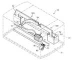
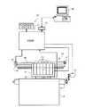
最初に、プリンタ10の構成の概略について説明する。図1は、本発明の一実施の形態に係るプリンタ10の概略構成を示す斜視図であり、紙送りの上流側を手前、紙送りの下流側(排紙側)を奥側に配置している状態を示す図である。また、図2は、プリンタ10の構成を示す概略図である。本実施の形態のプリンタ10は、シャーシ21と、ハウジング22と、キャリッジ機構30と、紙送り機構40と、インク供給機構50と、クリーニング機構60と、制御部70と、を具備している。<Schematic configuration of printer>
First, an outline of the configuration of the
これらのうち、シャーシ21は、その下面側が設置面に接触する部分であると共に、各種ユニットが搭載される部分である。また、このシャーシ21には、図1において二点鎖線で示されるハウジング22が取り付けられる。このハウジング22は、上述したシャーシ21と同様な平面形状を有している。 Among these, the
また、キャリッジ機構30は、図1および図2に示すように、キャリッジ31と、このキャリッジ31が摺動するキャリッジ軸32と、印刷ヘッド33と、を具備している。また、キャリッジ機構30は、キャリッジモータ(CRモータ)34と、このCRモータ34に取り付けられている歯車プーリ35と、無端のベルト36と、歯車プーリ35との間にこの無端のベルト36を張設する従動プーリ37と、を具備している。これらのうち、印刷ヘッド33(吐出ヘッドに対応)からは、後述するインク供給機構50を介して供給されるインク(液体に対応)が、印刷対象物Pに対して吐出される。 As shown in FIGS. 1 and 2, the
また、図2に示すように、紙送り機構40は、紙送りモータ(PFモータ)41と、この紙送りモータ41からの駆動力が伝達される給紙ローラ42等を具備している。 As shown in FIG. 2, the paper feed mechanism 40 includes a paper feed motor (PF motor) 41 and a
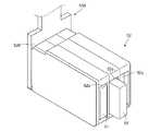
また、本実施の形態におけるプリンタ10は、インクカートリッジ51(液体供給源の一部に対応、液体貯留手段に対応)をシャーシ21側に装着する、いわゆるオフキャリッジタイプとなっている。そのため、プリンタ10のインク供給機構50(液体供給源に対応)は、図1に示すように、カートリッジホルダ52と、加圧ポンプ53と、空気チューブ54と、可撓性チューブ55と、サブタンク56と、を具備している。また、インク供給機構50は、これらの他に、板状チューブ500も有している。 The
これらのうち、図3に示すカートリッジホルダ52(液体供給源の一部に対応、装着部に対応)は、図4に示すインクカートリッジ51を搭載する部分であり、シャーシ21に対して固定的に取り付けられている。このカートリッジホルダ52には、インクカートリッジ51を差し込むための差込口52aが設けられている。また、このカートリッジホルダ52は、本実施の形態では、プリンタ10の内部であって主走査方向の端部側に、それぞれ1つずつ(合計2つ)設けられている。また、このカートリッジホルダ52のシャーシ21に対する取り付け位置は、キャリッジ31の移動空間域から外れる部位に設けられている。具体的には、カートリッジホルダ52は、キャリッジ31が長手方向において往復動する領域よりも、長手方向外側に設けられると共に、キャリッジ31の往復動の領域よりも例えば印刷対象物Pの排出側に取り付けられている。 Among these, the
なお、図7に示すように、このカートリッジホルダ52のうち、後述する板状チューブ500と対向する部位には、挿通孔52cが設けられている。この挿通孔52cは、後述する押し込みロッド91を挿通させるための孔である。また、この挿通孔52cを介して、カートリッジホルダ52には、押し込み機構90が取り付けられている。 As shown in FIG. 7, an
また、一対のカートリッジホルダ52には、差込口52aを介して、それぞれ複数(本実施の形態では3つずつ)のインクカートリッジ51が着脱自在に装着される。このインクカートリッジ51は、図4等に示すように、ケーシング51aの内部に空気室51bを具備しており、さらにこの空気室51bの内部にインクを充填するインクパック51cが収容されている。インクパック51cは、例えばアルミパックのような、気密性の高い袋状部材であり、このインクパック51cの内部には、インクが収容されている。 In addition, a plurality (three in this embodiment) of
また、図7に示すように、インクカートリッジ51は、インクパック51cの内部と連通するインク供給口51dを有しており、このインク供給口51dには、カートリッジホルダ52に存在するインク供給針52bが差し込まれる。また、インクカートリッジ51には、インク供給口51dを覆うように、不図示のフィルムが貼付されている。このインクカートリッジ51がカートリッジホルダ52に装着される場合、インク供給針52bがフィルムを突き破ると共に、インク供給針52bとインク供給口51dとが、インクの流通を可能とする状態で接続される。それにより、インクパック51c内のインクが、インク供給口51dを介して、後述する圧力緩衝室525側に供給可能となっている。 Further, as shown in FIG. 7, the
また、図7に示すように、インクカートリッジ51には、チューブ係合部51eが設けられている。このチューブ係合部51eは、空気室51bと連通していると共に、空気チューブ54の端末に設けられている、接続栓54bと係合する部分である。すなわち、インクカートリッジ51をカートリッジホルダ52に装着すると、チューブ係合部51eと接続栓54bとが係合する。そして、空気チューブ54から送り込まれる空気が、空気室51bの内部に導入可能となる。なお、インクカートリッジ51を取り外すと、チューブ係合部51eと接続栓54bとの係合が外れる。その場合、空気チューブ54の内部は、この接続栓54bを介して、大気開放される状態となる。 Further, as shown in FIG. 7, the
また、図1に示すように、カートリッジホルダ52には、加圧ポンプ53が接続されている。この加圧ポンプ53は、加圧手段の一部に対応し、空気チューブ54を介して、インクカートリッジ51内の空気室51bの内部に空気を送り込む。そして、この空気室51bの圧力を高めることにより、インクパック51cは押し潰されるように変形させられる。そして、この変形により、インクパック51c内に存在するインクは、板状チューブ500の内部に押し出され、当該板状チューブ500の内部に存在する圧力緩衝室525、第1インク流路532等をインクが流れる。なお、この板状チューブ500の構成の詳細については、後述する。 As shown in FIG. 1, a
また、空気チューブ54は、その一端側が加圧ポンプ53に接続されていると共に、その他端側が、接続栓54bとなっていて、その材質を例えばエラストマ樹脂等のような可撓性を有する材質から形成されている。この空気チューブ54は、加圧手段の一部に対応する。また、この空気チューブ54の接続栓54bは、チューブ係合部51eと係合する。そして、この係合状態において、加圧ポンプ53が作動すると、空気室51bの内部に空気を圧送することが可能となっている。 The
また、図1に示すように、板状チューブ500のうち、インクの流れの下流側の端部には、可撓性チューブ55の一端側が連結されている。この可撓性チューブ55は、エラストマ樹脂等のような、可撓性を有する材質から形成されている。それにより、可撓性チューブ55は、柔軟に可撓し、キャリッジ31の主走査方向における往復動を妨げない状態となっている。また、可撓性チューブ55には、その長手方向を貫く、中空のチューブ管路(図示省略)が存在している。そして、インク流路523,532,535と、チューブ管路とは連通して、インクを良好に流通させることを可能としている。 As shown in FIG. 1, one end of the
また、可撓性チューブ55の他端側には、サブタンク56が接続されている。このサブタンク56は、キャリッジ31の上部に、原則としてインクカートリッジ51と同じ個数だけ設けられている。このサブタンク56には、インク流路523,532,535およびチューブ管路を流通してきたインクが一時的に蓄えられる。なお、このサブタンク56に蓄えられるインクは、キャリッジ31の下面側に印刷ヘッド33から吐出される。 A sub tank 56 is connected to the other end of the
また、シャーシ21には、図1に示すようなクリーニング機構60が設けられている。このクリーニング機構60は、キャップ61と、吸引ポンプ62と、インク排出チューブ63とを備えている。これらのうち、キャップ61は、印刷ヘッド33のノズル形成面(不図示)を封止する部分である。かかる封止状態で、吸引ポンプ62が作動すると、インク排出チューブ63を介して、インクが不図示の廃液タンクに排出される。このインクの吸引動作により、板状チューブ500、可撓性チューブ55、または印刷ヘッド33等に混入している気泡を、強制的に排出する、いわゆるクリーニング動作を実行可能となっている。 The
また、図2に示すように、プリンタ10には、制御部70が設けられている。この制御部70は、インターフェース71、不図示のCPU、メモリ、ASIC(Application Specific Integrated Circuit)、バス、タイマ等を有している。また、この制御部70には、各種センサからの信号が入力されると共に、このセンサからの信号に基づいて、CRモータ34、PFモータ41、加圧ポンプ53のポンプモータ(図示省略)、吸引ポンプ62のポンプモータ(図示省略)、および印刷ヘッド33等の駆動を司る。 As shown in FIG. 2, the
また、プリンタ10は、インターフェース71を具備している。そして、プリンタ10は、このインターフェース71を介して、コンピュータ80に接続されている(図2参照)。なお、このコンピュータ80は、CPU、RAM、ROM、HDD(Hard Disk Drive)、インターフェース等を具備している(図示省略)。このうち、HDDには、画像を加工するためのアプリケーションプログラム、プリンタドライバプログラム、ビデオドライバプログラム等が記憶されている。 The
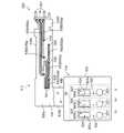
<押し込み機構の構成の詳細>
続いて、押し込み機構90の構成について、図7および図8に基づいて説明する。押し込み機構90は、押し込み手段に対応し、押し込みロッド91と、付勢手段に対応するコイルバネ92と、を構成要素として有している。これらのうち、押し込みロッド91は、ロッド部91Aと、押し込み部91Bと、受け部91Cと、を構成要素として有している。<Details of push-in mechanism configuration>
Next, the configuration of the push-in
上述の構成要素のうち、ロッド部91Aは、例えば円柱状を為すロッド状の部材であり、挿通孔52cに対して挿通自在に設けられる部分である。また、このロッド部91Aのうち、後述する液体滞留部525aと対向する側(一端側)には、押し込み部91Bが設けられている。この押し込み部91Bは、ロッド部91Aに対して一体的に設けられていても良いが、例えばロッド部91Aと押し込み部91Bとが、ネジにより嵌合する構成を採用しても良い。この押し込み部91Bは、ロッド部91Aよりも大径に設けられている。そのため、ロッド部91Aが液体滞留部525aから離間する向きにスライドする場合、押し込みロッド91が挿通孔52cから抜けるのを防止する、抜け止めとしての役割を有している。 Of the above-described components, the
また、この押し込み部91Bは、後述する撓みフィルム525bに当接する側が、その先端に向かうにつれて小径となるような凸形状に設けられている。そのため、撓みフィルム525bに押し込み部91Bが当接しても、その当接が滑らかとなると共に、撓みフィルム525bの損傷を抑えるように構成されている。なお、この押し込む部91Bは、その側面形状が台形状、半円形状等、種々の形状を採用することが可能である。 In addition, the pushing
また、ロッド部91Aのうち、他端側(押し込み部91Bが取り付けられる側とは反対側)には、受け部91Cが設けられている。この受け部91Cも、ロッド部91Aに対して一体的に設けられていても良く、例えばロッド部91Aと受け部91Cとが、ネジにより嵌合する構成を採用しても良い。この受け部91Cも、ロッド部91Aよりも大径に設けられている。そして、この受け部91Cは、液体滞留部525aと対向する側で、コイルバネ92を受け止めている。 In addition, a receiving
また、受け部91Cは、液体滞留部525aと対向しない側で、インクカートリッジ51と当接可能となっている。すなわち、インクカートリッジ51がカートリッジホルダ52に差し込まれると、図7に示すように、受け部91Cは、インクカートリッジ51のケーシング51aに当接する。このとき、受け部91Cは、コイルバネ92から付勢力を受ける状態で、ケーシング51aに当接している。また、図8に示すように、インクカートリッジ51がカートリッジホルダ52に差し込まれない状態(非装着状態)においては、受け部91Cは、コイルバネ92により、図8において右向き(液体滞留部525aから離間する向き)に向かって押し込まれる。 Further, the receiving
なお、図8に示すような、インクカートリッジ51の非装着状態においては、押し込み部91Bは、撓みフィルム525bに対して接触せずに、所定のクリアランスを有するように設けられている。また、図7に示すような、インクカートリッジ51が装着される状態においては、押し込み部91Bは、撓みフィルム525bを押し込むものの、その押し込み量は、液体滞留部525aの底部に到達しない程度に設けられている。 When the
また、コイルバネ92は、押し込みロッド91に対して、液体滞留部525aから離間する向きの付勢力を与える、付勢手段として機能する部分である。このコイルバネ92の軸心部には、ロッド部91Aが挿通している。また、このコイルバネ92の一端側は、カートリッジホルダ52の内壁に当接していると共に、当該コイルバネ92の他端側は、受け部91Cに当接している。そして、このコイルバネ92は、インクカートリッジ51が非装着状態のときに、最も伸張する状態となっているものの、その伸張状態においても、受け部91Cに対して若干の付勢力を及ぼすように設けられている。なお、コイルバネ92が最も伸張している状態においては、押し込み部91Aがカートリッジホルダ52の外壁に当接する状態となっている。 The
<板状チューブの構成の詳細>
続いて、圧力緩衝のための機構を有する、板状チューブ500の構成について、図1、図5〜図8等に基づいて説明する。図1に示すように、本実施の形態では、主走査方向に沿って、2つの板状チューブ500,500が設けられている。これら2つの板状チューブ500,500は、主走査方向における長さ寸法が異なる等の相違はあるものの、その構成要素は略同一であり、以下の説明においては、纏めて板状チューブ500として説明する。<Details of plate tube configuration>
Then, the structure of the plate-shaped
これら板状チューブ500は、チューブプレート510と、フィルム560とを主要な構成要素としている。これらのうち、チューブプレート510は、例えばアクリルといった、硬度が高い(硬質の)樹脂材を材質として形成されている。また、フィルム560は、例えば、ポリエチレンテレフタラート、ナイロン等のような、熱可塑性樹脂から形成されている。そして、このフィルム560は、チューブプレート510に対して熱圧着する等により取り付けられている。なお、このフィルム560は、複数の層が積層される構成を採用しても良い。かかる構成を採用する場合、上述の材質に対して、ポリプロピレン、又はポリエチレン等の複数の熱可塑性樹脂層を積層し、水蒸気を通過させない構成を採用することが可能である。 These plate-
ここで、図5に示すように、チューブプレート510は、ホルダ取付部520と、流路形成部530と、チューブ接続部550と、を有している。これらのうち、ホルダ取付部520は、カートリッジホルダ52に対して取付固定される部分であり、本実施の形態では、その外観が、平面視で略正方形を為すように設けられている。このホルダ取付部520のうち、下方側には、インクカートリッジ51の個数の分だけ(本実施の形態では3つ)、貫通孔521が設けられている。この貫通孔521には、加圧ポンプ53から空気を圧送する、空気チューブ54が挿通される。なお、空気チューブ54は、インクカートリッジ51の空気室51bに連通されており、当該空気室51bに空気を圧送して、インクパック51cを押し潰すことを可能としている。 Here, as shown in FIG. 5, the
また、上述の貫通孔521の上部には、インク流出孔522が設けられている。このインク流出孔522は、カートリッジホルダ52に設けられる、インク供給針52bに連通している。ここで、インクカートリッジ51をカートリッジホルダ52に搭載する場合、当該インクカートリッジ51のインク供給口51d(図4、図7参照)とインク供給針52bとが連結され、インクパック51c内のインクを、インク流出孔522から流出させることが可能となる。このインク流出孔522は、第1インク流路523へインクを流入させるための入口となっている。 In addition, an
また、インク流出孔522には、第1インク流路523を構成する第1溝部523aが連通している。この第1溝部523aは、チューブプレート510の他の部分よりも凹むように設けられる、溝状通路の部分である。また、この第1溝部523aは、チューブプレート510のうち、カートリッジホルダ52が取り付けられる側とは反対側の面に存在する。なお、以下の説明においては、チューブプレート510のうち、カートリッジホルダ52が取り付けられる側の面を裏面510b(図6で示される側の面)とすると共に、それとは反対側の面(図5で示される側の面)を表面510aとする。 The
この第1溝部523aは、ホルダ取付部520から流路形成部530に向かって延伸している。ここで、図5に示すように、流路形成部530は、平面視略L字状に形成されている。そして、第1溝部523aは、この略L字状の流路形成部530のうち、ホルダ取付部520から離間する向きの垂直部530aを延伸した後に、垂直部530aに対して直交する平行部530bとの付け根の部分に差し掛かる。ここで、当該付け根の部分には、貫通孔531が設けられている。この貫通孔531は、表面510a側で第1溝部523aと連通していると共に、裏面510b側で第2溝部532aと連通している。 The
また、図7に示すように、上述の第1溝部523aには、裏面510b側に向かう流通孔524が設けられている。この流通孔524は、液体滞留部525aと連通している。液体滞留部525aは、チューブプレート510の裏面510b側から表面510a側に向かって窪んでいる部分である。しかも、その窪んでいる位置は、上述の押し込み部91Bの押し込みに対応する位置となっている。また、この液体滞留部525aは、適度にインクを貯留することが可能なように、所定の面積を有して窪んでいる。 As shown in FIG. 7, the
また、図6、図7および図8に示すように、この液体滞留部525aを覆うように、撓み部材、フィルム部材としての撓みフィルム525bが貼付される。この撓みフィルム525bと、液体滞留部525aとにより、圧力緩衝室525が構成される。この撓みフィルム525bは、チューブプレート510の裏面510b側であって、上述の押し込み部91Bが当接する部位に設けられている。 Further, as shown in FIGS. 6, 7 and 8, a
なお、かかる圧力緩衝室525を構成する液体滞留部525a、および撓みフィルム525bは、圧力緩衝手段および容積変動手段に対応する。また、撓みフィルム525bは、撓み部材およびフィルム部材に対応する。 In addition, the
ここで、インクカートリッジ51が装着されると、撓みフィルム525bは、押し込み部91Bによって押し込まれ、圧力緩衝室525の内部の容積が、大幅に減じられる(図7参照)。しかしながら、インクカートリッジ51が取り外されると、撓みフィルム525bの押し込みが解除される。そのため、撓みフィルム525bは、液体滞留部525aの底部から離間する向きに向かい、容易に撓むことが可能となっている。 Here, when the
ここで、図6に示すように、平行部530bには、第2溝部532aが設けられている。この第2溝部532aは、後述するチョーク弁室541との干渉を避けるべく、平行部530bの裏面510b側に設けられている。この第2溝部532aは、裏面510bに対するフィルム560の貼付により、第2インク流路532を構成するものである。また、第2溝部532aの下流側の端部には、流入孔533が設けられている。この流入孔533は、平行部530bを貫通していることにより、次に述べるインク導入路534にインクを導入することを可能としている。なお、この流入孔533は、平行部530bの幅方向のうち、一端側(下方側)に位置している。 Here, as shown in FIG. 6, the
また、平行部530bの表面510a側には、合計3つのチョーク弁室541(図5参照)と、それぞれのチョーク弁室541に流入口542を介してインクを導くためのインク導入路534とをそれぞれ有している。このうち、インク導入路534には、流入孔533からインクが流入されるが、このインク導入路534の他端側は、流入口542においてチョーク弁室541に接続されている。なお、インク導入路534の他端側は、平行部530bの幅方向のうち、他端側(上方側)に位置している。 Further, a total of three choke valve chambers 541 (see FIG. 5) and an
また、このチョーク弁室541の略中央部には、排出孔543が設けられている。この排出孔543は、チョーク弁室541の底部541bから裏面510b側に向かい、平行部530bを貫通している。そして、この排出孔543は、裏面510b側で第3溝部535aと連通している。それにより、この排出孔543を介して、チョーク弁室541に流入されたインクを、第3溝部535aに向けて流出させることを可能としている。また、チョーク弁室541の底部において、排出孔543の周囲には、不図示の凸部が設けられている。この凸部は、チョーク弁室541の底部から表面側に向かい、リング状に突出している部分である。この凸部の頂部側にフィルム560が接離可能となっている。 In addition, a
なお、フィルム560は、チョーク弁室541の圧力と、フィルム560を挟んでチョーク弁室541とは反対側(外側)との圧力差に応じて、容易に撓むことを可能としている。ここで、チョーク弁室541が、外側の圧力よりも高くなると、フィルム560がチョーク弁室541の底部から離間する側に向かって撓む。この場合、凸部の頂部とフィルム560との間には、所定の隙間が存在する状態となる。そして、この隙間を介してインクが流通可能となり、排出孔543(第3溝部535a)に向けてインクを流通させることが可能となる。逆に、外側の圧力が、チョーク弁室541の圧力よりも高くなると、フィルム560がチョーク弁室541の底部に近接する側に向かって撓む。この場合、フィルム560は、凸部の頂部の全周に亘り、途切れることなく接触する。それにより、インクは、排出孔543を介して流出せず、その流れが遮断される。このようにして、チョーク弁540は、インクの流出の開閉を可能としている。 The
また、平行部530bには、第3溝部535aが設けられている。この第3溝部535aは、その一端が上述の排出孔543に連通していると共に、その他端側はチューブ接続部550に連通している。なお、この第3溝部535aは、フィルム560の貼付により第3インク流路535を構成する。また、第3溝部535aは、裏面510b側に設けられている。 The
また、チューブ接続部550は、可撓性チューブ55に接続される。ここで、チューブ接続部550には、パイプ状の接続管551が設けられていて、この接続管551が可撓性チューブ55のチューブ管路に差し込まれる等により、チューブ接続部550とチューブ管路とが連通する。 Further, the
<プリンタのインク供給に関する動作について>
以下、プリンタ10のインク供給に関する動作について説明する。インク供給に先立って、ユーザは、カートリッジホルダ52にインクカートリッジ51を装着しようとする。このとき、インクカートリッジ51が装着される前の段階では、図8に示すように、受け部91Cはケーシング51aに当接していない。そのため、コイルバネ92の付勢力により、押し込みロッド91は、その全体が液体滞留部525aから離間する位置に位置している。また、このとき、押し込み部91Bと撓みフィルム525bとは、所定の隙間を有する状態で、非接触となっている。<Operation related to ink supply of printer>
Hereinafter, an operation related to ink supply of the
この状態から、ユーザがインクカートリッジ51を差込口52aから差し込んで、装着しようとする。すると、インクカートリッジ51がカートリッジホルダ52の内部を進行するにつれて、受け部91Cがケーシング51aと衝突する。この状態から、更にインクカートリッジ51が進行すると、押し込みロッド91は、コイルバネ92の付勢力に抗しながら、液体滞留部525aの底部に向かって進行する。そして、インクカートリッジ51の正しい装着位置に到達するまで、押し込み部91Bは、撓みフィルム525bを、液体滞留部525aの底部側に向かって押し込む。 From this state, the user tries to insert the
以上のような装着状態において、インクカートリッジ51から、インクを供給可能な状態となる。そして、制御部70からの指令により、加圧ポンプ53が作動すると、空気チューブ54を介して空気が圧送され、空気室51bに供給される。そして、この空気の圧送により、インクパック51cは押し潰されるように変形させられる。それにより、インクがインク流出孔522を介して、流路(第1インク流路523、第2インク流路532、第3インク流路535、可撓性チューブ55のチューブ管路等)に、所定の圧力を及ぼしながら流れ出し、サブタンク56へと供給される。以上のようにして、インクが流路内に供給される。 In the mounting state as described above, ink can be supplied from the
ここで、上述のように、サブタンク56までの間に存在する流路へのインクの供給が開始される場合、流路内の内圧(液圧)は、大気圧よりも上昇する。そのため、圧力緩衝室525を構成する撓みフィルム525bも、液体滞留部525aの底部から離間する向きに向かって撓もうとするが、撓みフィルム525bは、押し込みロッド91によって押し込まれている。そのため、撓みフィルム525bは、液体滞留部525aの底部から離間する向きに向かっては撓めず、当該圧力緩衝室525の内部の体積(容積)は、液体滞留部525aの内部の体積(容積)よりも少ない状態となっている。 Here, as described above, when the supply of ink to the flow path existing up to the sub tank 56 is started, the internal pressure (hydraulic pressure) in the flow path rises higher than the atmospheric pressure. Therefore, the bending
ところで、例えば、コンピュータ80の画面表示等で、インク切れがアナウンスされると、ユーザは、インク切れとなっているインクカートリッジ51を交換しようとする。そして、インクカートリッジ51がユーザによって取り外される。このとき、受け部91Cとケーシング51aとの間の当接が解除され、押し込みロッド91は、コイルバネ92のバネ力に抗することができずに、液体滞留部525aから離間する向きに向かって移動させられる。それにより、押し込み部91Bは、撓みフィルム525bに対して所定の隙間を有する状態で、離間する(図8参照)。 By the way, for example, when the ink out is announced on the screen display of the
ここで、インクが流通する流路側(可撓性チューブ55、板状チューブ500等)においては、インクカートリッジ51を取り外す前の段階では、加圧ポンプ53の作動により、流路内の内圧が大気圧よりも高い状態となっている。そのため、インクカートリッジ51を取り外した瞬間に、弾性部材等で形成されている可撓性チューブ55等の内圧による膨張等の弾性力が開放され、その弾性力により、可撓性チューブ55が縮む等によってインクがインク供給針52bから噴出しよう、とする。 Here, on the flow channel side (
しかしながら、インクカートリッジ51を取り外すと、上述のように、押し込みロッド91による撓みフィルム525bの押し込みも解除される。そのため、図8に示すように、インク供給針52b側に向かおうとしたインクは、大気圧と流路内の内圧の差圧により、圧力緩衝室525の撓みフィルム525bを、液体滞留部525aの底部から離間させる方向に向かって撓ませる。このとき、流路内の内圧(液圧)の分だけ、撓みフィルム525bを撓ませることが可能となっている。それにより、圧力緩衝室525の内部の体積(容積)は増大し、インクは、インク供給針52bから、所定の勢いを持って噴出せずに、体積(容積)の増大分によって吸収される。 However, when the
なお、本実施の形態では、撓みフィルム525bが液体滞留部525aの底部から最大限離間しても、当該撓みフィルム525bと押し込み部91Bとが非接触を維持するように、各部の寸法が設定されている。 In the present embodiment, the dimensions of the respective parts are set so that the
<本発明を適用した場合における効果>
上述のプリンタ10によれば、インクを流通させる流路の中途部分に、圧力緩衝室525が設けられている。また、インクの供給状態においては、圧力緩衝室525は、押し込み部91Bにより撓みフィルム525bが押し込まれる状態にあるものの、インクカートリッジ51を取り外す場合には、押し込み部91Bによる押し込みが開放される状態となる。そのため、圧力緩衝室525は、インクカートリッジ51の取り外しに際して、押し込み状態からの開放により、内部の体積(容積)が増大する。それにより、流路が加圧状態にあり、インクがインク供給針52bから噴出しよう、としても、上述の内部体積(容積)の増大により、その噴出を抑えることが可能となる。それにより、インクカートリッジ51の取り外しの際に、インクが噴出して、カートリッジホルダ52や印刷対象物Pを汚してしまう、といった不具合が生じるのを防止可能となる。また、インクの噴出を抑えることが可能となるため、噴出したインクを受ける部分を別途設ける必要がなく、コストの増加を抑えることが可能となる。<Effect when the present invention is applied>
According to the
また、本実施の形態では、撓みフィルム525bは、押し込みロッド91による押し込みに応じて、液体滞留部525aの底部に接離する方向に撓む。そのため、押し込みロッド91での押し込みを開放させれば、圧力緩衝室525の内部の圧力(液圧)により、撓みフィルム525bが液体滞留部525aから離れる方向に撓み、圧力緩衝室525の内部容積が増大され、液体の圧力(液圧)を吸収可能となる。 Further, in the present embodiment, the bending
さらに、本実施の形態では、押し込みロッド91の受け部91Cは、インクカートリッジ51に当接して、その装着の際の押し込みを良好に受け止めることが可能となっている。また、インクカートリッジ51をカートリッジホルダ52から取り外す場合、コイルバネ92が受け部91Cを付勢するので、押し込み部91Bは、取り外しの動作に連動して、撓みフィルム525bから確実に離間させることが可能となる。 Further, in the present embodiment, the receiving
また、液体滞留部525aは、硬質のチューブプレート510に設けられていると共に、撓みフィルム525bは、薄膜状のフィルム部材となっている。このため、撓みフィルム525bは、インクの圧力(液圧)と加圧室527の圧力(空気圧)とに応じて、容易に撓みことが可能となる。また、撓みフィルム525bを用いる場合、容易に撓むため、当該撓みフィルム525bの撓みによっては、圧力緩衝室525側に反力が及ぼされない。そのため、撓みフィルム525bを液体滞留部525aの底部から離間する向きに撓ませた場合に、圧力緩衝室525側で圧力が上昇するのを抑えることが可能となる。 The
さらに、液体滞留部525aは、可撓性チューブ55よりも上流側の板状チューブ500に設けられている。ここで、可撓性チューブ55は、可撓性を備えるため、加圧ポンプ53等での加圧によって、膨張する方向に可撓する。そのため、インクカートリッジ51を取り外す場合、それまでの加圧状態の開放により、可撓性チューブ55が収縮しようとし、その収縮に伴って、インクが上流側に流れ出す。しかしながら、可撓性チューブ55よりも上流側に、液体滞留部525a(圧力緩衝室525)が存在するため、インクの圧力(液圧)を吸収可能となる。それにより、インクカートリッジ51の取り外しの際に、インクが噴出して、カートリッジホルダ52や印刷対象物Pを汚してしまう、といった不具合が生じるのを防止可能となる。
<第2の実施の形態>
以下、本発明の第2の実施の形態について、図9〜図12を用いて説明する。なお、本実施の形態は、上述の第1の実施の形態とかなる部分が共通しているため、同一の部分については同一の符号を用いると共に、主として第1の実施の形態との相違点について説明する。Furthermore, the
<Second Embodiment>
Hereinafter, a second embodiment of the present invention will be described with reference to FIGS. Since the present embodiment shares the same parts as the first embodiment described above, the same reference numerals are used for the same parts, and mainly the differences from the first embodiment. explain.
<第2の実施の形態における板状チューブの構成の詳細>
本実施の形態では、圧力緩衝室525とは相違する圧力緩衝室526が設けられている。すなわち、インク流出孔522には、圧力緩衝室526を構成する滞留凹部526aが連通している。図11、図12に示すように、圧力緩衝室526を構成する滞留凹部526aは、チューブプレート510の他の部分よりも凹むように設けられる部分である。また、この滞留凹部526aは、チューブプレート510のうち、カートリッジホルダ52が取り付けられる側とは反対側の面に存在する。<Details of the configuration of the plate-like tube in the second embodiment>
In the present embodiment, a
また、図9、図11および図12に示すように、この滞留凹部526aを覆うように、撓みフィルム526bが貼付される。この撓みフィルム526bと、滞留凹部526aとにより、圧力緩衝室526が構成される。この撓みフィルム526bは、チューブプレート510の表面510a側に取り付けられている。また、この撓みフィルム526bは、後述する加圧室527内の内圧に応じて、滞留凹部526aの底部から離間する方向に撓んだり、または滞留凹部526aの底部に向かって撓んだりする。 Further, as shown in FIGS. 9, 11 and 12, a
なお、かかる圧力緩衝室526を構成する滞留凹部526a、および撓みフィルム526bは、圧力緩衝手段および容積変動手段に対応する。また、撓みフィルム526bは、撓み部材およびフィルム部材に対応する。 The staying
また、図11等に示すように、上述の圧力緩衝室526を覆うように、ケース体527aが取り付けられている。このケース体527aは、加圧手段の一部に対応する。また、ケース体527aは、一方側が開放した箱状の外観を呈している。また、ケース体527aは、その開放側が表面510aに向く状態で取付固定されている。この取付固定は、ケース体527aの内部に流入する空気が外部に漏れない状態で、表面510aに取付固定される。それにより、圧力緩衝室526を密閉状態で覆う、加圧室527が構成される。また、このケース体527aのうち、正面視した場合に圧力緩衝室526と対向しない部位(図9においては下方側)には、チューブ挿通孔527bが設けられている。このチューブ挿通孔527bは、空気チューブ54を挿通させるための孔である。なお、空気チューブ54は、このチューブ挿通孔527bを挿通した後に、上述の貫通孔521を挿通する。 Moreover, as shown in FIG. 11 etc., the
また、空気チューブ54には、この空気チューブ54の管路と連通する連通孔54aが設けられている。この連通孔54aは、加圧室527に連通している。そのため、加圧ポンプ53が作動して、空気を圧送する場合、圧送される空気は、空気チューブ54を介して空気室51b側に送られると共に、加圧室527にも送られる状態となる。このため、空気室51bと加圧室527とは、おおむね同じ圧力(略等しい圧力)に保たれる。 Further, the
ここで、インクカートリッジ51が装着されて、インクをサブタンク56側に向けて供給する状態においては、加圧ポンプ53が作動し、空気チューブ54を介して空気が空気室51bに送られる。それにより、インクパック51cが押し潰されて、インクが板状チューブ500側へ流れ出し、圧力緩衝室526へと流れ込む。そのため、圧力緩衝室526の内圧(液圧)は、上昇する。しかしながら、加圧ポンプ53の作動状態においては、空気は空気チューブ54を介して加圧室527にも供給されている。このため、加圧室527の内圧(空気圧)も上昇する。そのため、撓みフィルム526bは、滞留凹部526aの底部から離間する方向には撓まずに、表面510aと概略平行な状態となる。 Here, in a state where the
また、インクカートリッジ51を取り外す場合、空気チューブ54は、接続栓54bを介して大気開放される状態となるので、加圧室527が大気開放され、その内圧が大気圧と同じ状態まで低下する。一方、インクが流通する流路側(可撓性チューブ55、板状チューブ500等)においては、インクカートリッジ51を取り外す前の段階では、内圧が高い状態であるため、インクカートリッジ51を取り外した瞬間に、流路の内圧と大気開放された加圧室527との間の差圧により、撓みフィルム526bが滞留凹部526aの底部から離間する側に撓む。それにより、インクがインク供給針52bから噴出しよう、とするのが防止可能となっている。 When the
また、滞留凹部526aには、貫通孔528の一端側が設けられている。この貫通孔528は、表面510a側で滞留凹部526aと連通していると共に、裏面510b側で第1溝部532a(以下、本実施の形態では、第1の実施の形態における第2溝部532aを第1溝部532a、第1の実施の形態における第2インク流路532を第1インク流路532として説明する。)と連通している(図10参照)。この第1溝部532aは、裏面510bに対するフィルム560の貼付により、第1インク流路532を構成するものである。また、第1溝部532aは、図10に示すように、ホルダ取付部520から流路形成部530に向かって延伸している。また、第1溝部532aは、流路形成部530の垂直部530aおよび平行部530bに形成されている。 Further, one end side of the through
<第2の実施の形態におけるプリンタのインク供給に関する動作について>
以下、第2の実施の形態における、プリンタ10のインク供給に関する動作について説明する。インク供給に先立って、カートリッジホルダ52にユーザがインクカートリッジ51を正しく装着し、インクを供給可能な状態となる。そして、制御部70からの指令により、加圧ポンプ53が作動すると、空気チューブ54を介して空気が圧送され、空気室51bに供給される。また、空気チューブ54には、連通孔54aが存在しているので、圧送される空気の一部は、この連通孔54aを介して、加圧室527にも供給される。<Operation Related to Ink Supply of Printer in Second Embodiment>
Hereinafter, an operation related to the ink supply of the
また、上述のように、空気室51bに空気が圧送されるので、この空気の圧送によってインクパック51cが押し潰される。そして、インクが、インク供給口51dおよびインク供給針52bを介して、インク流出孔522へと流入する。その後、インクは、圧力緩衝室526、第1インク流路532、チョーク弁室541、第2インク流路535、チューブ接続部550、可撓性チューブ55を介して、サブタンク56へと供給される。 Further, as described above, since the air is pumped to the
また、上述のように、サブタンク56までの間に存在する流路へのインクの供給が開始される場合、流路内の内圧(液圧)は、大気圧よりも上昇する。そのため、圧力緩衝室526を構成する撓みフィルム526bも、滞留凹部526aの底部から離間する向きに向かって撓もうとするが、加圧室527の内圧(空気圧)と、流路内の内圧(液圧)とは同じ加圧ポンプ53の作動に応じて変動し、これらの内圧は互いに対応する関係(本実施の形態においては、略等しい状態)にある。そのため、加圧ポンプ53の作動状態においては、撓みフィルム526bは、図11に示すように、表面510aと概ね平行な状態となる。 Further, as described above, when the supply of ink to the flow path existing up to the sub tank 56 is started, the internal pressure (hydraulic pressure) in the flow path rises above the atmospheric pressure. Therefore, the
ところで、例えば、コンピュータ80の画面表示等で、インク切れがアナウンスされると、ユーザは、インク切れとなっているインクカートリッジ51を交換しようとする。そして、インクカートリッジ51がユーザによって取り外される。このとき、インク供給口51dとインク供給針52bとの接続状態が解除されると共に、チューブ係合部51eと接続栓54bとの係合(接続)も解除される。 By the way, for example, when the ink out is announced on the screen display of the
ここで、インクが流通する流路側(可撓性チューブ55、板状チューブ500等)においては、インクカートリッジ51を取り外す前の段階では、加圧ポンプ53の作動により、流路内の内圧が大気圧よりも高い状態となっている。そのため、インクカートリッジ51を取り外した瞬間に、弾性部材等で形成されている可撓性チューブ55等の内圧による膨張等の弾性力が開放され、その弾性力により、可撓性チューブ55が縮む等によってインクがインク供給針52bから噴出しよう、とする。 Here, on the flow channel side (
しかしながら、インクカートリッジ51を取り外すと、空気チューブ54は、接続栓54bを介して大気開放される状態となっている。そのため、加圧室527も大気開放され、その内圧が大気圧と同じ状態となる。そのため、図12に示すように、インク供給針52b側に向かおうとしたインクは、加圧室527の内圧と圧力緩衝室526の内圧の差圧により、圧力緩衝室526の撓みフィルム526bを、滞留凹部526aの底部から離間させる方向に向かって撓ませる。このとき、流路内の内圧(液圧)の分だけ、撓みフィルム526bを撓ませることが可能となっている。それにより、圧力緩衝室526の内部の体積(容積)は増大し、インクは、インク供給針52bから、所定の勢いを持って噴出せずに、体積(容積)の増大分によって吸収される。 However, when the
<第2の実施の形態に係る発明を適用した場合における効果>
上述の構成によれば、インクを流通させる流路の中途部分に、圧力緩衝室526が設けられている。また、インクの供給状態においては、加圧室527は、その内圧(空気圧)は加圧状態にあるものの、インクカートリッジ51を取り外す場合には、加圧室527が大気開放される状態となる。そのため、圧力緩衝室526は、インクカートリッジ51の取り外しに際して、加圧状態からの開放により、内部の体積(容積)が増大する。それにより、流路が加圧状態にあり、インクがインク供給針52bから噴出しよう、としても、上述の内部体積(容積)の増大により、その噴出を抑えることが可能となる。それにより、インクカートリッジ51の取り外しの際に、インクが噴出して、カートリッジホルダ52や印刷対象物Pを汚してしまう、といった不具合が生じるのを防止可能となる。また、インクの噴出を抑えることが可能となるため、噴出したインクを受ける部分を別途設ける必要がなく、コストの増加を抑えることが可能となる。<Effect when the invention according to the second embodiment is applied>
According to the above-described configuration, the
また、本実施の形態では、撓みフィルム526bは、空気圧に応じて、滞留凹部526aの底部に接離する方向に撓む。そのため、インクカートリッジ51をカートリッジホルダ52から取り外す際には、この撓みフィルム526bの撓みにより、圧力緩衝室526の内部容積が容易に増大され、インクの圧力(液圧)を吸収可能となる。 Moreover, in this Embodiment, the bending
さらに、本実施の形態では、ケース体527aにより加圧室527を形成し、この加圧室527には、連通孔54aを介して加圧ポンプ53から圧送される空気が導入される。それにより、加圧室527の内部を加圧状態とすることが可能となり、インクの供給状態においては、撓みフィルム526bを加圧室527側から押し込む状態に維持可能となる。換言すれば、インクカートリッジ51の取り外しに際しては、加圧室527の加圧状態が開放され、加圧による撓みフィルム526bの押し込み状態を維持できず、撓みフィルム526bが加圧室527に突出する向きに撓む。それにより、圧力緩衝室526の内部容積が増加し、インクの噴出を防止可能となる。 Further, in the present embodiment, the pressurizing
また、滞留凹部526aは、硬質のチューブプレート510に設けられていると共に、撓みフィルム526bは、薄膜状のフィルム部材となっている。このため、撓みフィルム526bは、インクの圧力(液圧)と加圧室527の圧力(空気圧)とに応じて、容易に撓みことが可能となる。また、撓みフィルム526bを用いる場合、容易に撓むため、当該撓みフィルム526bの撓みによっては、圧力緩衝室526側に反力が及ぼされない。そのため、撓みフィルム526bを加圧室527側に撓ませた場合に、圧力緩衝室526側で圧力が上昇するのを抑えることが可能となる。 The
さらに、滞留凹部526aは、可撓性チューブ55よりも上流側の板状チューブ500に設けられている。ここで、可撓性チューブ55は、可撓性を備えるため、加圧ポンプ53等での加圧によって、膨張する方向に可撓する。そのため、インクカートリッジ51を取り外す場合、加圧状態の開放により、可撓性チューブ55が収縮しようとし、その収縮に伴って、インクが上流側に流れ出す。しかしながら、可撓性チューブ55よりも上流側に、滞留凹部526a(圧力緩衝室526)が存在するため、インクの圧力(液圧)を吸収可能となる。それにより、インクカートリッジ51の取り外しの際に、インクが噴出して、カートリッジホルダ52や印刷対象物Pを汚してしまう、といった不具合が生じるのを防止可能となる。 Further, the
また、加圧室527と圧力緩衝室526とは、加圧ポンプ53の作動時には、略等しい圧力となっている。このため、撓みフィルム526bは、加圧室527に向かって撓まずに、平衡状態を維持可能となる。 Further, the
<本発明の変形例>
以上、本発明の第1および第2の実施の形態について説明したが、本発明はこれ以外にも種々変形可能となっている。以下、それについて述べる。<Modification of the present invention>
Although the first and second embodiments of the present invention have been described above, the present invention can be variously modified in addition to this. This will be described below.
上述の各実施の形態では、容積変動手段に該当する圧力緩衝室525,526は、板状チューブ500に設けられる構成を採用している。しかしながら、圧力緩衝室525,526は、板状チューブ500に設けられる必要はなく、例えば圧力緩衝室525,526とインク供給針52bとを1ユニットとし、板状チューブ500のインク流出孔522に対して着脱可能に構成しても良い。このとき、圧力緩衝室525,526としては、ビニール等の袋状部材を利用しても良く、その場合、撓み部材は、このビニール等の袋状部材が該当する。また、このとき、袋状部材は、容積変動手段に該当する。 In each of the above-described embodiments, the
また、上述の第1の実施の形態では、押し込み手段として、押し込みロッド91とコイルバネ92を具備する押し込み機構90を用いている。しかしながら、押し込み手段は、かかる押し込み機構90には限られない。例えば、インクカートリッジ51の押し込みにより、押し込み部91Bが撓みフィルム525bを押し込む構成とはせずに、例えばモータ等のアクチュエータ、または空気圧を利用する等により、押し込み部91Bが撓みフィルム525bを押し込むと共に、インクカートリッジ51の取り外しと同期して押し込み部91Bが撓みフィルム525bを押し込むのを解除するように構成しても良い。 Further, in the above-described first embodiment, the pushing
また、上述の第1の実施の形態においては、押し込み機構90のコイルバネ92を設ける必要はなく、省略する構成を採用しても良い。また、例えば側面視T字形状のゴムブッシュを、押し込み機構90の代わりに用いるようにしても良い。 In the first embodiment described above, it is not necessary to provide the
また、上述の第1の実施の形態では、撓み部材として撓みフィルム525bを用いている。しかしながら、撓み部材としては、例えば薄板状のプレート部材を用いると共に、このプレート部材として、非押圧状態において液体滞留部525aの底部から離間する向きの不バネ力を有するものを用いても良い。このようにすれば、押し込みロッド91で押し込まない状態においては、プレート部材は確実に液体滞留部525aの底部から離間し、圧力緩衝部525の体積を即座に増大させることが可能となり、インクの噴出を一層確実に防止可能となる。 Further, in the first embodiment described above, the
また、上述の第2の実施の形態では、加圧手段として、ケース体527a、空気チューブ54、および加圧ポンプ53を用いている。しかしながら、加圧手段はこれらには限られない。例えば、ケース体527aの代わりに、ビニール等で形成されていると共に空気チューブ54に連通する袋状部材を用い、この袋状部材で圧力緩衝室526を覆うように構成しても良い。加圧ポンプ53とは別途のポンプを用いる等により、加圧室527の内部を加圧する構成を用いても良い。 In the second embodiment described above, the
また、上述の第2の実施の形態では、空気チューブ54は、連通孔54aを介して、当該空気チューブ54を流通する空気の一部が加圧室527に流れ込む構成を採用している。しかしながら、空気チューブ54から圧送される空気が、全て加圧室527に導入される構成を採用しても良い。この場合、例えば2本の空気チューブを用いるようにしても良い。2本の空気チューブを用いる場合、例えば、加圧ポンプ53に第1の空気チューブの一端側が接続されると共に、当該第1の空気チューブの他端側が加圧室527に接続される。また、第2の空気チューブの一端側が加圧室527に接続されると共に、当該第2の空気チューブの他端側にチューブ係合部51eと係合(接続)される接続栓54bを設けるようにする。 In the second embodiment described above, the
このようにすれば、加圧室527には、加圧ポンプ53からの圧力がいち早く及ぼされると共に、大気開放された場合に、加圧室527の内部の空気が、より早く第2の空気チューブの他端側から逃げる状態となり、加圧室527をより早く大気開放させることが可能となる。 In this way, the pressure from the pressurizing
また、上述の各実施の形態におけるプリンタ10は、プリンタ機能以外の機能(スキャナ機能、コピー機能等)を備える構成のような、複合的な機器の一部であっても良い。また、液体吐出装置は、プリンタ10には限られない。プリンタ10以外の液体吐出装置としては、液晶ディスプレイ、ELディスプレイ等の製造に用いられる、液体を噴射する装置等がある。また、液体は、インク以外の液体であっても良く、たとえば液晶ディスプレイ、ELディスプレイに用いられる液体を噴射する装置においては、色材、電極材が液体となる。 Further, the
10…プリンタ、30…キャリッジ機構、31…キャリッジ、33…印刷ヘッド(吐出ヘッドに対応)、50…インク供給機構(液体供給源に対応)、51…インクカートリッジ(液体供給源の一部および液体貯留手段に対応)、52…カートリッジホルダ(液体供給源の一部および装着部に対応)、52c…挿通孔、53…加圧ポンプ(加圧手段の一部に対応)、54…空気チューブ(加圧手段の一部に対応)、55…可撓性チューブ、70…制御部、80…コンピュータ、90…押し込み機構(押し込み手段に対応)、91…押し込みロッド、91A…ロッド部、91B…押し込み部、91C…受け部、92…コイルバネ(付勢手段に対応)、500…板状チューブ、510…チューブプレート、510a…表面、510b…裏面、520…ホルダ取付部、524…流通孔、525,526…圧力緩衝室(圧力緩衝手段、容積変動手段に対応)、526a…滞留凹部(圧力緩衝手段の一部、容積変動手段の一部に対応)、526b…撓みフィルム(圧力緩衝手段の一部、容積変動手段の一部、撓み部材、フィルム部材に対応)、527…加圧室(加圧手段に対応)、527a…ケース体(加圧手段の一部に対応)、532…第1インク流路、535…第2インク流路、541…チョーク弁室、550…チューブ接続部、560…フィルム DESCRIPTION OF
Claims (2)
Translated fromJapanese上記液体を内部に貯留する液体貯留手段と、上記液体を供給するための液体供給口と、上記液体貯留手段を加圧する空気を導入するための係合部と、を有する液体供給源と、
上記液体供給口と接続して、上記液体を上記吐出ヘッドに向けて流通させる流路と、
滞留凹部を覆う撓みフィルムで構成される液体滞留部であって、上記流路の中途部分に設けられ、上記撓みフィルムの撓みに応じて内部の容積が変動する液体滞留部と、
上記係合部と接続する空気チューブと、
上記空気チューブの連通孔を介し、上記空気チューブの管路と連通するとともに上記撓みフィルムとケース体とで画定される加圧室を具備し、
上記液体供給源が装着され、上記液体供給口と上記流路、および上記係合部と上記空気チューブが接続される場合、上記撓みフィルムは、上記滞留凹部の底部から離間する方向には撓まずに上記液体が上記流路の下流側に供給可能な状態をなし、
上記液体供給源が取り外され、上記液体供給口と上記流路、および上記係合部と上記空気チューブが接続解除される場合、上記撓みフィルムは、上記滞留凹部の底部から離間する方向に撓むことを特徴とする液体吐出装置。An ejection head for ejecting liquid toward an ejection target;
A liquid storage unit that stores the liquidtherein, a liquid supply port for supplying the liquid, a liquid supply source thathaving a an engaging portion for introducing air to pressurize the liquid storage ,
A flow path thatconnects to theliquid supply port and distributes the liquid toward the discharge head;
A liquid retention part composed of a flexible film covering the retention recess , provided in the middle of the flow path, and aliquid retention part whose internal volume varies according tothe deflection of theflexible film ;
An air tube connected to the engaging portion;
Via a communication hole of the air tube, and a pressure chamber defined by the flexible film and the case body, and communicating with the duct of the air tube;
When the liquid supply source is mounted and the liquid supply port and the flow path, and the engagement portion and the air tube are connected, the flexible film does not flex in a direction away from the bottom of the staying recess. The liquid can be supplied to the downstream side of the flow path,
When the liquid supply source is removed and the liquid supply port, the flow path, and the engagement portion and the air tube are disconnected, the flexible film bends in a direction away from the bottom of the staying recess. A liquid discharge apparatus characterized by that.
上記液体供給口と接続して、上記液体を流通させる流路と、
滞留凹部を覆う撓みフィルムで構成される液体滞留部であって、上記流路の中途部分に設けられ、上記撓みフィルムの撓みに応じて内部の容積が変動する液体滞留部と、
上記係合部と接続する空気チューブと、
上記空気チューブの連通孔を介し、上記空気チューブの管路と連通するとともに上記撓みフィルムとケース体とで画定される加圧室を具備する液体供給装置における液体供給方法であって、
上記液体供給口と上記流路、および上記係合部と上記空気チューブが接続される場合、上記撓みフィルムは、上記滞留凹部の底部から離間する方向には撓まずに上記液体が上記流路の下流側に供給可能な状態をなし、
上記液体供給口と上記流路、および上記係合部と上記空気チューブが接続解除される場合、上記撓みフィルムは、上記滞留凹部の底部から離間する方向に撓む、ことを特徴とする液体供給方法。A liquid supply source having a liquid storage means for storing the liquid therein, a liquid supply port for supplying the liquid, and an engaging portion for introducing air for pressurizing the liquid storage means;
A flow path for connecting the liquid supply port and circulating the liquid;
A liquid retention part composed of a flexible film covering the retention recess, provided in the middle of the flow path, and a liquid retention part whose internal volume varies according to the deflection of the flexible film;
An air tube connected to the engaging portion;
A liquid supply methodin a liquid supply apparatus comprising a pressurizing chamber that is communicated with a pipe line of the air tube via a communication hole of the air tube and defined by the flexible film and the case body ,
When the liquid supply port and the flow path, and the engagement portion and the air tube are connected, the flexible film does not bend in the direction away from the bottom of the retention recess, and the liquid does not flow in the flow path. It is possible to supply to the downstream side,
When the connection between the liquid supply port and the flow path, and the engagement portion and the air tube is released, the flexible film bends in a direction away from the bottom of the retention recess. Method.
Priority Applications (2)
| Application Number | Priority Date | Filing Date | Title |
|---|---|---|---|
| JP2007072014AJP4345833B2 (en) | 2007-03-20 | 2007-03-20 | Liquid ejection apparatus and liquid supply method |
| US12/050,531US7992977B2 (en) | 2007-03-20 | 2008-03-18 | Liquid ejecting apparatus and liquid supply method |
Applications Claiming Priority (1)
| Application Number | Priority Date | Filing Date | Title |
|---|---|---|---|
| JP2007072014AJP4345833B2 (en) | 2007-03-20 | 2007-03-20 | Liquid ejection apparatus and liquid supply method |
Publications (2)
| Publication Number | Publication Date |
|---|---|
| JP2008230011A JP2008230011A (en) | 2008-10-02 |
| JP4345833B2true JP4345833B2 (en) | 2009-10-14 |
Family
ID=39774256
Family Applications (1)
| Application Number | Title | Priority Date | Filing Date |
|---|---|---|---|
| JP2007072014AExpired - Fee RelatedJP4345833B2 (en) | 2007-03-20 | 2007-03-20 | Liquid ejection apparatus and liquid supply method |
Country Status (2)
| Country | Link |
|---|---|
| US (1) | US7992977B2 (en) |
| JP (1) | JP4345833B2 (en) |
Families Citing this family (8)
| Publication number | Priority date | Publication date | Assignee | Title |
|---|---|---|---|---|
| JP5789999B2 (en)* | 2011-01-31 | 2015-10-07 | セイコーエプソン株式会社 | Liquid ejector |
| JP6060544B2 (en)* | 2012-05-23 | 2017-01-18 | セイコーエプソン株式会社 | Liquid container and container unit |
| GB201209685D0 (en)* | 2012-05-31 | 2012-07-18 | Sericol Ltd | Ink package |
| US9827776B2 (en) | 2012-07-23 | 2017-11-28 | Seiko Epson Corporation | Method and apparatus for manufacturing cartridge |
| JP6048004B2 (en) | 2012-07-23 | 2016-12-21 | セイコーエプソン株式会社 | cartridge |
| US10384454B2 (en) | 2012-07-23 | 2019-08-20 | Seiko Epson Corporation | Refilled cartridge and method for manufacturing refilled cartridge |
| JP6069964B2 (en) | 2012-07-23 | 2017-02-01 | セイコーエプソン株式会社 | Cartridge manufacturing method, injection kit, and injection device |
| USD726252S1 (en) | 2013-08-19 | 2015-04-07 | Seiko Epson Corporation | Cap for an ink cartridge |
Family Cites Families (8)
| Publication number | Priority date | Publication date | Assignee | Title |
|---|---|---|---|---|
| JPH08174860A (en)* | 1994-10-26 | 1996-07-09 | Seiko Epson Corp | Ink cartridge for inkjet printer |
| JP4141523B2 (en)* | 1997-03-19 | 2008-08-27 | セイコーエプソン株式会社 | Ink supply flow path valve device |
| EP2108513B1 (en)* | 1998-07-15 | 2011-05-04 | Seiko Epson Corporation | Ink supply unit |
| JP3669240B2 (en) | 2000-02-01 | 2005-07-06 | セイコーエプソン株式会社 | Inkjet recording device |
| CA2469450C (en)* | 2000-10-20 | 2010-02-23 | Seiko Epson Corporation | Ink cartridge for ink jet recording device |
| JP3991853B2 (en)* | 2002-09-12 | 2007-10-17 | セイコーエプソン株式会社 | ink cartridge |
| JP2007050666A (en) | 2005-08-19 | 2007-03-01 | Fujifilm Corp | Ink jet recording system, ink cartridge, and ink jet recording apparatus |
| JP4806616B2 (en)* | 2006-09-29 | 2011-11-02 | 富士フイルム株式会社 | Ink cartridge and ink jet recording apparatus |
- 2007
- 2007-03-20JPJP2007072014Apatent/JP4345833B2/ennot_activeExpired - Fee Related
- 2008
- 2008-03-18USUS12/050,531patent/US7992977B2/ennot_activeExpired - Fee Related
Also Published As
| Publication number | Publication date |
|---|---|
| JP2008230011A (en) | 2008-10-02 |
| US20080231672A1 (en) | 2008-09-25 |
| US7992977B2 (en) | 2011-08-09 |
Similar Documents
| Publication | Publication Date | Title |
|---|---|---|
| JP4345833B2 (en) | Liquid ejection apparatus and liquid supply method | |
| US6652080B2 (en) | Re-circulating fluid delivery system | |
| JP3977355B2 (en) | Ink tank and recording head | |
| CN102131647B (en) | image forming equipment | |
| JP2004188720A (en) | Liquid storage container | |
| EP3456541B1 (en) | Liquid ejecting apparatus and control method of liquid ejecting apparatus | |
| TW200408541A (en) | Liquid supply system, fluid communicating structure, ink supply system, and inkjet recording head utilizing the fluid communicating structure | |
| JP2005103859A (en) | Ink supply system, recording apparatus, recording head, and liquid supply system | |
| JP4873697B2 (en) | Inkjet recording device | |
| JP4560401B2 (en) | Ink tank and ink jet recording apparatus | |
| JP5073596B2 (en) | Image forming apparatus | |
| JP4047258B2 (en) | Liquid supply system | |
| CN106476440A (en) | Buffer unit, liquid-supplying system and inkjet recording device | |
| JP5381296B2 (en) | Ink cartridge and image forming apparatus | |
| JP4047256B2 (en) | Ink supply system and ink tank | |
| JP4941033B2 (en) | Liquid ejection device | |
| JP2009160931A (en) | Liquid ejection apparatus, printing apparatus, and liquid supply method | |
| JP5742171B2 (en) | printer | |
| JP2009226722A (en) | Fluid jetting apparatus | |
| JP5007586B2 (en) | Valve unit and fluid ejection device | |
| JP4645070B2 (en) | Valve device and liquid injection device | |
| JP2005279962A (en) | Fluid communication structure, ink jet recording head and apparatus using the fluid communication structure | |
| JP2012045767A (en) | Ink tank | |
| JP2005343123A (en) | Pressure reducing valve, carriage and liquid ejecting apparatus | |
| JP2016147468A (en) | Liquid ejector |
Legal Events
| Date | Code | Title | Description |
|---|---|---|---|
| A977 | Report on retrieval | Free format text:JAPANESE INTERMEDIATE CODE: A971007 Effective date:20090121 | |
| A131 | Notification of reasons for refusal | Free format text:JAPANESE INTERMEDIATE CODE: A131 Effective date:20090127 | |
| A521 | Written amendment | Free format text:JAPANESE INTERMEDIATE CODE: A523 Effective date:20090303 | |
| TRDD | Decision of grant or rejection written | ||
| A01 | Written decision to grant a patent or to grant a registration (utility model) | Free format text:JAPANESE INTERMEDIATE CODE: A01 Effective date:20090623 | |
| A01 | Written decision to grant a patent or to grant a registration (utility model) | Free format text:JAPANESE INTERMEDIATE CODE: A01 | |
| A61 | First payment of annual fees (during grant procedure) | Free format text:JAPANESE INTERMEDIATE CODE: A61 Effective date:20090706 | |
| R150 | Certificate of patent or registration of utility model | Free format text:JAPANESE INTERMEDIATE CODE: R150 | |
| FPAY | Renewal fee payment (event date is renewal date of database) | Free format text:PAYMENT UNTIL: 20120724 Year of fee payment:3 | |
| FPAY | Renewal fee payment (event date is renewal date of database) | Free format text:PAYMENT UNTIL: 20120724 Year of fee payment:3 | |
| FPAY | Renewal fee payment (event date is renewal date of database) | Free format text:PAYMENT UNTIL: 20130724 Year of fee payment:4 | |
| S531 | Written request for registration of change of domicile | Free format text:JAPANESE INTERMEDIATE CODE: R313531 | |
| R350 | Written notification of registration of transfer | Free format text:JAPANESE INTERMEDIATE CODE: R350 | |
| LAPS | Cancellation because of no payment of annual fees |