JP4345113B2 - Pachinko machine - Google Patents
Pachinko machineDownload PDFInfo
- Publication number
- JP4345113B2 JP4345113B2JP24227798AJP24227798AJP4345113B2JP 4345113 B2JP4345113 B2JP 4345113B2JP 24227798 AJP24227798 AJP 24227798AJP 24227798 AJP24227798 AJP 24227798AJP 4345113 B2JP4345113 B2JP 4345113B2
- Authority
- JP
- Japan
- Prior art keywords
- lamp
- frame
- substrate
- window
- glass
- Prior art date
- Legal status (The legal status is an assumption and is not a legal conclusion. Google has not performed a legal analysis and makes no representation as to the accuracy of the status listed.)
- Expired - Fee Related
Links
- 239000000758substrateSubstances0.000claimsdescription68
- 239000011521glassSubstances0.000claimsdescription62
- 210000000078clawAnatomy0.000claimsdescription23
- 238000005034decorationMethods0.000claimsdescription11
- 230000002093peripheral effectEffects0.000claimsdescription6
- 238000003780insertionMethods0.000description18
- 230000037431insertionEffects0.000description18
- 238000000465mouldingMethods0.000description6
- 125000006850spacer groupChemical group0.000description6
- 238000000034methodMethods0.000description4
- 238000010586diagramMethods0.000description3
- 230000000694effectsEffects0.000description3
- 239000002184metalSubstances0.000description3
- 229920003002synthetic resinPolymers0.000description3
- 239000000057synthetic resinSubstances0.000description3
- 229920005989resinPolymers0.000description2
- 239000011347resinSubstances0.000description2
- 230000005489elastic deformationEffects0.000description1
- 238000009434installationMethods0.000description1
- 239000002932lusterSubstances0.000description1
- 230000007257malfunctionEffects0.000description1
- 238000004064recyclingMethods0.000description1
Images


Landscapes
- Pinball Game Machines (AREA)
Description
Translated fromJapanese【0001】
【発明の属する技術分野】
本発明は、パチンコ機に関し、さらに詳しくは、パチンコ機前面に設けられた遊技領域を覆う前枠に関する。
【0002】
【従来の技術】
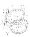
図12に示す従来のパチンコ機81には、機枠が周設されており、機枠上半部の左側縁に、ガラス板83を備えた前枠84が、片開き自在に設置されている。ガラス板83の後方には、遊技球が流下する遊技領域82が設けられている。また、前枠84は、図13に示すように、ランプ飾り85、装飾体86、前方枠87、ガラス板83を嵌入した後方枠88、下方装飾体89などからなり、ランプ飾り85には、ランプ91,91・・を搭載したランプ基板92,92・・が螺着されている。ランプ基板91には、ランプ92,92・・が、全体に亘り互いに近接した状態で載置されている。
【0003】
【発明が解決しようとする課題】
従来のパチンコ機81では、ランプ基板92が、前方枠87の前面に取り付けられた、幅の狭いランプ飾り85に螺着されているため、基板を安定して取り付けるために、多くのネジが必要となる。また、ランプ基板92が、直にランプ飾り85に螺着されているため、ランプ基板92の上下や左右や取り付け位置を取り違えて取り付けられる可能性があり、さらにランプ91,91・・は、ランプ基板92一面に設けられているため、取り違えて螺着された場合には、ランプ91やランプ基板92の破損、ひいてはパチンコ機81の作動不良を生じてしまう。
【0004】
よって、本発明のうち、請求項1,2に記載の課題は、ランプ基板を、方向や配置を取り違えることなく、簡易な構成で安定して取り付けることができるパチンコ機を提供することにある。また、上記課題にくわえて、ランプ基板を容易に取り付けることができるパチンコ機を提供することにある。
【0005】
【課題を解決するための手段】
本発明のうち、請求項1に記載の発明は、前面に遊技領域が設けられているとともに、窓枠の後側にガラス枠を組み付けてなる前枠が、遊技領域前方に位置するように、片開き自在に設けられており、さらに、窓枠の前側に、ランプによって点灯するランプ飾りを備えているパチンコ機であって、前記ガラス枠の前面に、前記ランプを設置したランプ基板を係止するための係止爪を設けるとともに、前記ガラス枠に、前記ランプの端子を後方に露出可能なランプ孔を設ける一方、前記窓枠の後面に、前記ランプ基板を嵌め込み可能な凹部を設けるとともに、前記窓枠の前記凹部内となる位置に、前記ランプを露出する為のランプ窓、及び前記係止爪を嵌入可能な爪用孔を穿設し、前記ガラス枠の前面に前記ランプ基板を係止させた後、当該ランプ基板を前記凹部内に位置させ、前記ランプを前記ランプ窓内に、前記係止爪を前記爪用孔内に夫々位置させることで、前記窓枠の後面と前記ガラス枠の前面とを近接させたことを特徴とする。
【0006】
また、請求項2に記載の発明は、前記ガラス枠の前面に、係止状態にある前記ランプ基板の後面外周縁に当接する基板用リブを前方へ突設したことを特徴とする。
【0008】
【発明の実施の形態】
以下、本発明の実施形態につき、図面に基づいて説明する。図1および図2は、本発明に係るパチンコ機前部の斜視説明図であって、パチンコ機には、外枠2が周設されており、外枠2の左上コーナー部には、連結部3が突設され、左下コーナー部には、本体枠連結金具4が取り付けられている。そして、連結部3と本体枠連結金具4とに、本体枠が枢着されている。本体枠は3層構造であり、前から順に、表枠5、内部機構(図示せず)を支持したミドル枠6、機構板(図示せず)となっている。表枠5は、外枠2とほぼ同寸の薄板7と、薄板7前面の左側縁に片開き自在に設けられる、前枠8および中扉9と、中扉9の下方に取り付けられる下側機能部10などからなる。なお、薄板7の後面に、ミドル枠6が固定されている。また、ミドル枠6には、前面に遊技領域が形成された、内部機構の一部としての遊技盤が支持されており、前枠8後方に遊技領域が位置している。さらに、中扉9は、供給皿11を備えており、下部機能部10は、貯留皿12を備えている。
【0009】
図3から図5は前枠8の説明図であって、前枠8は、窓枠15およびガラス枠16などからなる。窓枠15は、大別して、窓枠本体20とランプ飾り21とからなる。一方、ガラス枠16は、大別して、ガラス枠本体22とガラス板23とからなる。図6から図8に、ランプ飾り21と窓枠本体20とガラス枠本体22とを示す。
【0010】
窓枠本体20は、下部を切り欠いた円形のほぼ遊技領域大である開口部24を中央に有する、合成樹脂製の部材であって、開口部24の下方には、開口部24下部と相似形で、他の部分より前側と下側とに突出した段状の延長部26が設けられている。また、延長部26辺部を含む開口部24前面周辺には、周囲部25が、前方へ向けて突設されている。さらに、周囲部25のすぐ内側であって、窓枠本体20のコーナー部付近には、挿通孔27,27・・が設けられている。またさらに、上方と下方との挿通孔27,27・・の間には、ランプ窓28,28・・が、5個ずつ縦一列に並設されている。また、最上方および最下方のランプ窓28,28・・に近接した、周囲部25の内側には、爪用孔29,29・・が設けられている。なお、延長部26は、中扉9前面に当接可能である。
【0011】
くわえて、窓枠本体20の上辺縁前面中央には回動部材用孔30が、回動部材用孔30の両脇には上ランプ用孔31,31が開けられており、さらに上ランプ用孔31,31の側方には上ランプ基板台32,32と上ランプ基板係止爪33,33とが突設されており、またさらに上ランプ基板係止爪33,33の側方には、スピーカー部34,34が、開口部を有する箱状に突出成形されている。回動部材用孔30には、回動部材52が、先端膨出形の回動軸を、回動部材用孔30に挿通することによって、回動可能に取り付けられている。回動軸先端は、回動部材用孔30に、弾性変形によって通す。また、上ランプ基台32,32には、上ランプ飾り18を点灯する上ランプを備えた、上ランプ基板(図示せず)が、上ランプ基板係止爪33によって取り付けられている。さらに、スピーカー部34には、スピーカー49,49が嵌め込まれている。なお、上ランプは、上ランプ基板のすぐ後方において束ねられたコード(図示せず)によって、パチンコ機内部の制御装置(図示せず)に連結されている。コードは、片方の上ランプ基板用孔31を通されている。また、スピーカーも制御装置と連結されている。
【0012】
また、前枠本体20の左上コーナー部には、切除部35が形成されており、切除部35下方と、前枠本体20の左下コーナー部とには、それぞれ、膨出部36,37が、前方へ半円錐状に突設されている。なお、膨出部36上面に設けられた上軸孔37に、連結部3の下面に配置された上突出軸(図示せず)の先端縁が挿入されている。上突出軸は、ミドル枠6の枢着部下面に突設されている。また、連結部3下面と膨出部36との間であって、上突出軸周囲に、スペーサ38が設けられている。スペーサ38は、膨出部36上面に開けられた串刺し孔39と、スペーサ38自体に設けられた串刺し孔(図示せず)とを共通して貫く串刺し部材40によって取り付けられている。スペーサ38の装着により、連結部3の突出軸を隠し、さらに膨出部36と連続形状となって見栄えが良いし、前枠8の上下のがたつきを抑え、スペーサ38を外せば、前枠8を上にずらして下部枢着部を外し、続いて上部枢着部を外して、前枠8を外すことができる。また、切除部35は、スペーサ38と連結部3との厚さ分の深さを有し、連結部3と窓枠15の切除部35以外の上辺を揃える。
【0013】
さらに、窓枠本体20後面であって、各サイドのランプ窓28,28・・が設けられた部分には、凹部76が形成されている。なお、窓枠本体20は、発泡倍率を1.05程度としたカウンタープレッシャー成形法により一体成形されている。カウンタープレッシャー成形法の採用により、ガラス枠16を支えるために十分な強度が、一体成形したリブの作用と相まって、軽量で薄く形成しても得ることができるし、複雑な形状の窓枠本体20を、個体間のばらつきがほとんどない状態で容易に成型することができるようになる。
【0014】
また、ランプ飾り21は、内周を窓枠本体20の開口部24と同寸とし、外周を周囲部と同形状とした、断面山形の輪状部材であって、周方向に段部を有する。また、ランプ飾り21両サイド部の段部内側には、透明な透光窓50,50が形成されている。さらに、各透光窓50の上下には、先端矢尻状の挿通片51,51が、後方へ突設されている。なお、ランプ飾り21は合成樹脂製であって、インモールド成形法により成形されている。成形時、透光窓50,50に当たる部分に孔を有する金属光沢を備えたシートを、予め成形室の壁に添設しておくことにより、ランプ飾り21は、各透光窓50以外に金属光沢を備えた状態で一体成形される。成形後、前記シートが樹脂に若干埋め込まれた状態となっており、シートがはがれず、樹脂とシートの光沢が調和する。
【0015】
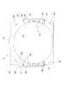
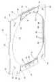
一方、ガラス枠本体22は、図9から図11に示すように、中央に窓枠本体20の開口部24と同寸の開口部54を備えた合成樹脂製の枠であって、外形を、窓枠本体20の後面における最も内側のリブの配置とほぼ同形状として形成されている。すなわち、上辺中央には、当接片55が、上方へ延設されており、両側部にはそれぞれ、左側翼56,右側翼57が張り出されている。そして、各側翼56,57前面には、それぞれ、基板用リブ58,59が、前方へ突出した状態で、内側に開口したコの字状に配置されている。さらに、基板用リブ58,59で包囲された部分には、ガラス枠16の開口部54に沿った状態で、5つずつ、ランプ孔60,60・・が設けられている。またさらに、基板用リブ58,59の上下辺のコーナー付近には、それぞれ、爪基部孔62,62・・が開けられており、先端矢尻状の係止爪61が、各爪基部孔62後方から前方へ突出した状態で、ガラス枠本体22と一体的に形成されている。なお、ガラス枠本体22のそれぞれのコーナー部には、挿通片係止孔63が設けられている。
【0016】
そして、基板用リブ58,59の前側には、それぞれ、ランプ基板70,71が設けられている。ランプ基板70は、基板用リブ58と、開口部54外方とに沿って形成されており、LEDランプ72,72・・を、数個ずつ5箇所に分けて搭載している。また、ランプ基板70の上下辺コーナー付近には、係止部73,73が形成されている。さらに、各係止部73には、係止爪61が、ランプ基板70を後方の基板用リブ58へ押し付けた状態で嵌入されている。なお、各LEDランプ72は、コード(図示せず)によって、パチンコ機の制御装置に接続されており、コードは、1つにまとめられて、中央のランプ孔60に挿通されている。また、ランプ基板70は、基板用リブ58によって、取り付け部の強度を上げ安定して取り付けられるし、後面外方を覆われるため、LEDランプ72の基板との接合部が保護される。さらに、ランプ孔60により、ランプ基板70のLEDランプ72,72・・との接合部における端子などの突出部と干渉することがない。そして、右側翼57前面のランプ基板71も、ランプ基板70と同様に形成され、取り付けられる。なお、窓枠15の各凹部76外周は、それぞれ、ランプ基板70,71の外形と同形状に形成されている。
【0017】
さらに、ガラス枠本体22後面には、両サイドおよび下辺のそれぞれの全体に亘って、レールリブ65,65・・が、後方へ突設されている。また、サイドのレールリブ65,65の端部以外の内面、および、下辺のレールリブ65の内面全体には、それぞれ3本ずつ、ガラス保持片67,67・・が突設されており、それぞれのレールリブ65において、中央のガラス保持片67と後方のガラス保持片67との間が、ガラス挿入レール66とされている。なお、前方のガラス保持片67と中央のガラス挿入片67との間には、小リブ68,68・・が渡されている。また、両側翼56,57後面には、側リブ78,79が、後方へ突設されている。さらに、各係止爪61は、側リブ78,79を基部として突設されている。
【0018】
そして、ガラス挿入レール66にガラス板23を嵌め込んでなるガラス枠16は、ランプ飾り21などを窓枠本体20に取り付けた窓枠15の後面のリブ内に、回動部材52をガラス枠16上部の当接片55に当接し、さらに各挿通片51を、窓枠15の挿通孔27に挿通した上、ガラス枠本体22の挿通片係止孔63に挿通して後側で係止することによって、取り付けられている。窓枠15とガラス枠16とは、挿通片51,51・・が共通して貫通されるため、互いに強固に組み付けられる。この組み付けは、挿通片51,51・・先端の矢尻部分を係止するのみで、容易にネジを必要とせず行える。
【0019】
ガラス枠16が取り付けられた状態では、ランプ基板70,71上のLEDランプ72,72・・が、数個ずつ窓枠のランプ窓28,28・・の後方から前方へ、周囲に若干余裕を持って露出し(図5)、そして、透光窓50,50の後方に位置している(図4(b))。このとき、ランプ基板70,71前部が、窓枠15の凹部76,76にそれぞれ位置している。また、係止爪61,61・・の先端が、爪用孔29,29・・に内部に位置している。
【0020】
このようなパチンコ機では、ガラス枠16に取り付けられたランプ基板70,71上のLEDランプ72,72・・が、窓枠15のランプ窓28,28・・を通じて露出された状態で、ランプ飾り21の透光窓50,50後方に配置されているので、透光窓50,50を介して、開口部34,54周囲を電飾することができる。しかも、ランプ基板70,71は、窓枠15とほぼ同じ大きさであってリブを備えたガラス枠16に取り付けられるため、安定する。さらに、ランプ基板70,71を取り付ける際、LEDランプ72,72・・の配置に対応して設けられたランプ窓28,28・・にLEDランプ72,72・・を通すため、ランプ基板70,71の向きや配置を取り違える事態を防止できる。なお、ランプ基板70,71前部が、凹部76,76に位置しているので、LEDランプ72,72・・をランプ窓28,28から十分に突出させて透光窓50,50に近づけることができるし、ランプ基板70,71を取り付けたガラス枠16を、窓枠15に十分近づけて収納することができる。また、ランプ基板70,71は、それぞれ、ガラス枠16と一体形成された係止爪61,61によって取り付けるので、ネジなどが必要なく。シンプルに形成でき、取り付けも非常に容易である。また、取り付けにネジを要しないため、パチンコ機をリサイクルもしくは破棄する場合において、分解・分別が非常に行いやすい。上ランプ基板32の取り付けにおいても、ランプ基板70,71と同様である。
【0021】
なお、本発明は、上記実施形態に限定されるものではなく、次に一部示すように様々に変更可能である。ランプ基板は、ガラス枠前面に取り付けられる必要はなく、側翼部の後面に基板用リブを配し、係止爪を突設し、さらに、ガラス枠に、窓枠のランプ窓と対応したランプ窓を設けて、基板前面に基板用リブを当接し、基板後面に係止爪を係止した状態で、LEDランプを、双方のランプ窓を通じて露出させて、取り付けることができる。この場合においても、ランプ基板の安定性や、向き・配置の取り違え防止効果は、何ら変わることがない。
【0022】
また、ランプ基板の形状や取り付け方法、LEDランプの配置は、上記実施形態に限られることはない。同様に、基板用リブや、ランプ窓・ランプ孔の配置も、上記実施形態に限られることはない。さらに、ランプ窓から露出されるLEDランプの個数も、数個に限られることはなく、1個ずつでも良いし、多数であっても良い。くわえて、ランプの種類は、LEDランプに限られることはなく、電球や蛍光灯などの他のランプを採用できる。挿通片は、窓枠とガラス枠とを挿通する必要はなく、窓枠のみを挿通しても良い。そして、本発明は、窓枠に対しガラス枠が片開きするパチンコ機や前枠と中扉とが一体となったパチンコ機など、他のパチンコ機に、また、パチンコ機以外の他の遊技機に適用することができる。
【0023】
【発明の効果】
本発明うち、請求項1,2に記載の発明は、ガラス枠にランプ基板を取り付け、さらに、ランプを露出可能なランプ窓を設けたので、ランプ基板を、方向や配置を取り違えることなく、簡易な構成で安定して取り付けることができ、ランプ基板の破損やパチンコ機の作動不良を防止できる、という効果を奏する。また、ガラス枠と一体形成された係止爪によって、ランプ基板を係止するので、上記効果を備えるとともに、ランプ基板を容易に取り付けることができるし、ネジを用いないので適正なリサイクル・破棄作業が行いやすい。
請求項1,2に記載の発明は、ランプ基板前部が、凹部に位置しているので、ランプをランプ窓から十分に突出させて透光窓に近づけることができるし、ランプ基板を取り付けたガラス枠を、窓枠に十分近づけて収納することができる。また、ランプ孔により、ランプ基板のランプとの接合部における端子などの突出部と干渉することがない。
それに加えて請求項2に記載の発明は、ランプ基板が、基板用リブによって、取り付け部の強度を上げ安定して取り付けられるし、後面外方を覆われるため、ランプの基板との接合部が保護される。
【図面の簡単な説明】
【図1】本発明に係るパチンコ機の前部前側を示す斜視説明図である。
【図2】パチンコ機の前部後側を示す斜視を示す説明図である。
【図3】前枠の(a)前側,(b)後側を示す斜視説明図である。
【図4】前枠の(a)正面,(b)(a)のD−D断面を示す説明図である。
【図5】前枠の一部分解説明図である。
【図6】飾り部材、窓枠本体、およびガラス枠本体の一部分解説明図である。
【図7】窓枠本体とガラス枠本体との(a)平面,(b)正面,(c)右側面,(a)底面を示す説明図である。
【図8】窓枠本体とガラス枠本体との背面を示す説明図である。
【図9】ガラス枠本体の正面を示す説明図である。
【図10】ガラス枠本体とランプ基板とを示す説明図である。
【図11】ガラス枠本体とランプ基板とを示す分解説明図である。
【図12】従来例を示す説明図である。
【図13】従来例を示す説明図である。
【符号の説明】
2・・外枠、3・・連結部、5・・表枠、6・・ミドル枠、7・・薄板、8・・前枠、9・・中扉、10・・下側機能部、11・・供給皿、12・・貯留皿、15・・窓枠、16・・ガラス枠、18・・上ランプ、20・・窓枠本体、21・・ランプ飾り、22・・ガラス枠本体、23・・ガラス板、24・・(窓枠)開口部、25・・周囲部、26・・延長部、27・・挿通孔、28・・ランプ孔、29・・爪用孔、30・・回動部材用孔、31・・上ランプ用孔、32・・上ランプ基板、33・・上ランプ基板係止爪、34・・スピーカー部、35・・切除部、36,37・・膨出部、38・・スペーサ、39・・串刺し孔、40・・串刺し部材、43,44,45・・リブ、50・・透光窓、51・・挿通片、52・・回動部材、54・・(ガラス枠)開口部、55・・当接片、56・・左側翼、57・・右側翼、58,59・・基板用リブ、60・・ランプ孔、61・・係止爪、62・・爪基部孔、63・・挿通片係止孔、65・・レールリブ、66・・ガラス挿入レール、67・・ガラス保持片、68・・小リブ、70,71・・ランプ基板、72・・LEDランプ、73・・係止部、78,79・・側リブ。[0001]
BACKGROUND OF THE INVENTION
The present invention relates to a pachinko machine, and more particularly to a front frame that covers a game area provided on the front surface of the pachinko machine.
[0002]
[Prior art]
The
[0003]
[Problems to be solved by the invention]
In the
[0004]
Therefore, the subject of
[0005]
[Means for Solving the Problems]
Among the present invention, the invention according to claim 1 is provided with a game area on the front surface, and a front frame formed by assembling a glass frame on the rear side of the window frame is positioned in front of the game area. provided freely open piece, further, the front side of the window frame, a pachinko machine and a lamp ornament lighted by the lamp, a front surface ofthe glassframe,lock the ramp substrate placedthe lampWhile providing a locking claw for doing, while providing a lamp hole in the glass frame that can expose the terminal of the lamp rearward, on the rear surface of the window frame is provided with a recess into which the lamp substrate can be fitted, A lamp window for exposing the lamp and a claw hole into which the locking claw can be inserted are formed at a position in the recess of the window frame, and the lamp substrate is engaged with the front surface of the glass frame. After stopping The rear surface of the window frame and the front surface of the glass frame are brought close to each other by positioning the glass substrate in the recess, positioning the lamp in the lamp window, and the locking claw in the claw hole. It was made to be characterized.
[0006]
The invention described in
[0008]
DETAILED DESCRIPTION OF THE INVENTION
Hereinafter, embodiments of the present invention will be described with reference to the drawings. 1 and 2 are perspective explanatory views of a front portion of a pachinko machine according to the present invention, wherein the
[0009]
3 to 5 are explanatory views of the
[0010]
The window frame
[0011]
In addition, a
[0012]
In addition, a
[0013]
Further, a
[0014]
The
[0015]
On the other hand, the glass frame
[0016]
In addition,
[0017]
Further,
[0018]
The
[0019]
When the
[0020]
In such a pachinko machine, the
[0021]
In addition, this invention is not limited to the said embodiment, As shown below in part, it can be variously changed. The lamp substrate does not need to be attached to the front surface of the glass frame. The ribs for the substrate are arranged on the rear surface of the side wing part, the locking claw is projected, and the lamp window corresponding to the lamp window of the window frame is provided on the glass frame. The LED lamp can be exposed and attached through both lamp windows in a state where the substrate rib is brought into contact with the front surface of the substrate and the locking claws are locked to the rear surface of the substrate. Even in this case, the stability of the lamp substrate and the effect of preventing the misunderstanding of the direction and the arrangement are not changed at all.
[0022]
Further, the shape of the lamp substrate, the mounting method, and the arrangement of the LED lamps are not limited to the above embodiment. Similarly, the arrangement of the substrate ribs and the lamp windows / lamp holes is not limited to the above embodiment. Further, the number of LED lamps exposed from the lamp window is not limited to several, and may be one by one or many. In addition, the type of the lamp is not limited to the LED lamp, and other lamps such as a light bulb and a fluorescent lamp can be adopted. The insertion piece does not need to be inserted through the window frame and the glass frame, and only the window frame may be inserted. The present invention is also applicable to other pachinko machines such as a pachinko machine in which a glass frame is opened to a window frame or a pachinko machine in which a front frame and an inner door are integrated, and other gaming machines other than pachinko machines. Can be applied to.
[0023]
【The invention's effect】
Among the present inventions, the invention described in
In the first and second aspects of the present invention, since the front part of the lamp substrate is located in the recess, the lamp can be sufficiently protruded from the lamp window to be close to the translucent window, and the lamp substrate is attached. The glass frame can be stored close enough to the window frame. In addition, the lamp hole does not interfere with a protruding portion such as a terminal at a joint portion of the lamp substrate with the lamp.
In addition, the invention according to
[Brief description of the drawings]
FIG. 1 is an explanatory perspective view showing a front front side of a pachinko machine according to the present invention.
FIG. 2 is an explanatory view showing a perspective view showing a front rear side of the pachinko machine.
FIG. 3 is a perspective explanatory view showing (a) front side and (b) rear side of a front frame.
FIGS. 4A and 4B are explanatory diagrams showing a DD section of (a) the front and (b) and (a) of the front frame;
FIG. 5 is a partially exploded explanatory view of a front frame.
FIG. 6 is a partially exploded explanatory view of a decorative member, a window frame main body, and a glass frame main body.
7A and 7B are explanatory views showing (a) a plane, (b) a front, (c) a right side, and (a) a bottom of a window frame main body and a glass frame main body.
FIG. 8 is an explanatory view showing the back surfaces of the window frame main body and the glass frame main body.
FIG. 9 is an explanatory view showing the front of the glass frame main body.
FIG. 10 is an explanatory view showing a glass frame body and a lamp substrate.
FIG. 11 is an exploded explanatory view showing a glass frame body and a lamp substrate.
FIG. 12 is an explanatory diagram showing a conventional example.
FIG. 13 is an explanatory diagram showing a conventional example.
[Explanation of symbols]
2 .. Outer frame 3 ..
Claims (2)
Translated fromJapanese前記ガラス枠の前面に、前記ランプを設置したランプ基板を係止するための係止爪を設けるとともに、前記ガラス枠に、前記ランプの端子を後方に露出可能なランプ孔を設ける一方、
前記窓枠の後面に、前記ランプ基板を嵌め込み可能な凹部を設けるとともに、前記窓枠の前記凹部内となる位置に、前記ランプを露出する為のランプ窓、及び前記係止爪を嵌入可能な爪用孔を穿設し、
前記ガラス枠の前面に前記ランプ基板を係止させた後、当該ランプ基板を前記凹部内に位置させ、前記ランプを前記ランプ窓内に、前記係止爪を前記爪用孔内に夫々位置させることで、前記窓枠の後面と前記ガラス枠の前面とを近接させたことを特徴とするパチンコ機。A game area is provided on the front side, and a front frame formed by assembling a glass frame on the rear side of the window frame is provided so as to be freely opened so as to be positioned in front of the game area. A pachinko machine equipped with a lamp decoration that is lit by a lamp on the front side,
Whileproviding a locking claw for locking the lamp substrate on which the lamp is installed on the front surface ofthe glass frame, the glass frameis provided with a lamp hole capable of exposing the lamp terminal to the rear,
The rear surface of the window frame is provided with a recess into which the lamp substrate can be fitted, and the lamp window for exposing the lamp and the locking claw can be fitted in a position in the recess of the window frame. Drill holes for nails,
After the lamp substrate is locked to the front surface of the glass frame, the lamp substrate is positioned in the recess, the lamp is positioned in the lamp window, and the locking claw is positioned in the claw hole. Thus , a pachinko machine in whichthe rear surface of the window frame and the front surface of the glass frame are brought close to each other .
Priority Applications (1)
| Application Number | Priority Date | Filing Date | Title |
|---|---|---|---|
| JP24227798AJP4345113B2 (en) | 1998-08-27 | 1998-08-27 | Pachinko machine |
Applications Claiming Priority (1)
| Application Number | Priority Date | Filing Date | Title |
|---|---|---|---|
| JP24227798AJP4345113B2 (en) | 1998-08-27 | 1998-08-27 | Pachinko machine |
Publications (2)
| Publication Number | Publication Date |
|---|---|
| JP2000070514A JP2000070514A (en) | 2000-03-07 |
| JP4345113B2true JP4345113B2 (en) | 2009-10-14 |
Family
ID=17086878
Family Applications (1)
| Application Number | Title | Priority Date | Filing Date |
|---|---|---|---|
| JP24227798AExpired - Fee RelatedJP4345113B2 (en) | 1998-08-27 | 1998-08-27 | Pachinko machine |
Country Status (1)
| Country | Link |
|---|---|
| JP (1) | JP4345113B2 (en) |
- 1998
- 1998-08-27JPJP24227798Apatent/JP4345113B2/ennot_activeExpired - Fee Related
Also Published As
| Publication number | Publication date |
|---|---|
| JP2000070514A (en) | 2000-03-07 |
Similar Documents
| Publication | Publication Date | Title |
|---|---|---|
| USD421799S (en) | Combined adaptor cover, blade irons, motor housing and light fixture unit for a ceiling fan | |
| US7036188B1 (en) | Composite knob with light pipe leakage barrier | |
| USD414856S (en) | Combined ceiling fan and light fixture | |
| US7553062B2 (en) | Light device | |
| USD414857S (en) | Combined ceiling fan and light fixture | |
| JP2008200362A (en) | Game machine | |
| EP1647767B1 (en) | Light assembly | |
| JP3570786B2 (en) | Gaming machine | |
| JP4235378B2 (en) | Pachinko machine | |
| USD407154S (en) | Combined motor housing, blade irons and light fixture unit for a ceiling fan | |
| USD413378S (en) | Combined ceiling fan and light fixture | |
| JP3767926B2 (en) | Game machine | |
| JP4345113B2 (en) | Pachinko machine | |
| JP4345114B2 (en) | Pachinko machine | |
| JP2005270179A (en) | Game machine | |
| JPH05309159A (en) | Lighting equipment for game machine | |
| KR200270052Y1 (en) | Contact Breaker Box Cover | |
| USD408519S (en) | Combined motor housing, blade irons and light fixture unit for a ceiling fan | |
| JP4014664B2 (en) | Bullet ball machine | |
| JPH10286358A (en) | Pachinko machine | |
| JPH0327654Y2 (en) | ||
| JP2000061104A (en) | Pachinko machine | |
| JP4733302B2 (en) | Vehicle ashtray | |
| JPH0838718A (en) | Pachinko game machine | |
| JP2000084211A (en) | Pachinko machine |
Legal Events
| Date | Code | Title | Description |
|---|---|---|---|
| A621 | Written request for application examination | Free format text:JAPANESE INTERMEDIATE CODE: A621 Effective date:20050826 | |
| A977 | Report on retrieval | Free format text:JAPANESE INTERMEDIATE CODE: A971007 Effective date:20081119 | |
| A131 | Notification of reasons for refusal | Free format text:JAPANESE INTERMEDIATE CODE: A131 Effective date:20081209 | |
| A521 | Written amendment | Free format text:JAPANESE INTERMEDIATE CODE: A523 Effective date:20090130 | |
| TRDD | Decision of grant or rejection written | ||
| A01 | Written decision to grant a patent or to grant a registration (utility model) | Free format text:JAPANESE INTERMEDIATE CODE: A01 Effective date:20090623 | |
| A01 | Written decision to grant a patent or to grant a registration (utility model) | Free format text:JAPANESE INTERMEDIATE CODE: A01 | |
| A61 | First payment of annual fees (during grant procedure) | Free format text:JAPANESE INTERMEDIATE CODE: A61 Effective date:20090706 | |
| R150 | Certificate of patent or registration of utility model | Free format text:JAPANESE INTERMEDIATE CODE: R150 | |
| FPAY | Renewal fee payment (event date is renewal date of database) | Free format text:PAYMENT UNTIL: 20120724 Year of fee payment:3 | |
| FPAY | Renewal fee payment (event date is renewal date of database) | Free format text:PAYMENT UNTIL: 20120724 Year of fee payment:3 | |
| FPAY | Renewal fee payment (event date is renewal date of database) | Free format text:PAYMENT UNTIL: 20150724 Year of fee payment:6 | |
| R250 | Receipt of annual fees | Free format text:JAPANESE INTERMEDIATE CODE: R250 | |
| LAPS | Cancellation because of no payment of annual fees |