JP4344571B2 - Cleaning tool - Google Patents
Cleaning toolDownload PDFInfo
- Publication number
- JP4344571B2 JP4344571B2JP2003325697AJP2003325697AJP4344571B2JP 4344571 B2JP4344571 B2JP 4344571B2JP 2003325697 AJP2003325697 AJP 2003325697AJP 2003325697 AJP2003325697 AJP 2003325697AJP 4344571 B2JP4344571 B2JP 4344571B2
- Authority
- JP
- Japan
- Prior art keywords
- holding
- elastic
- support
- cleaning
- dimension
- Prior art date
- Legal status (The legal status is an assumption and is not a legal conclusion. Google has not performed a legal analysis and makes no representation as to the accuracy of the status listed.)
- Expired - Fee Related
Links
Images


Landscapes
- Cleaning Implements For Floors, Carpets, Furniture, Walls, And The Like (AREA)
Description
Translated fromJapanese本発明は、不織布、繊維の束、布、糸、紙などで形成された清掃用品を保持する保持ヘッドを備えた清掃用保持具に係り、特に、前記保持ヘッドが自由に変形できる清掃用保持具に関する。 The present invention relates to a cleaning holder having a holding head for holding a cleaning article formed of a nonwoven fabric, a bundle of fibers, a cloth, a thread, paper, etc., and in particular, a cleaning holder in which the holding head can be freely deformed. Concerning ingredients.
従来、不織布、繊維の束、布、糸、紙あるいはこれらの素材を組み合わせて形成された清掃用品が使用されている。また、前記清掃用品を保持する清掃用保持具として、把持柄の先に保持ヘッドが設けられたものが一般に使用されている。清掃用品は前記保持ヘッドに装着され、前記保持ヘッドで前記清掃用品が床面などの被清掃物に押さえつけられ、保持ヘッドを動かすことにより、清掃用品で被清掃物の表面が拭かれる。 Conventionally, a non-woven fabric, a bundle of fibers, a cloth, a thread, paper, or a cleaning article formed by combining these materials has been used. Further, as a cleaning holder for holding the cleaning article, a tool provided with a holding head at the tip of a grip handle is generally used. The cleaning article is mounted on the holding head, the cleaning article is pressed against the object to be cleaned such as a floor surface by the holding head, and the surface of the object to be cleaned is wiped with the cleaning article by moving the holding head.
以下の特許文献1には、清掃用品であるモップを保持する装着プレートと、前記装着プレートに連結された把持柄とを有するモップ装着具が開示されている。この装着プレートは弾性係数の高い合成樹脂で形成されているが、この装着プレートの2箇所に透孔が形成されて湾曲変形可能な構造となっている。この装着プレートを湾曲変形させることにより、前記装着プレートの両側部を清掃用品であるモップの袋部分に挿入できるようにしている。 The following Patent Document 1 discloses a mop wearing tool having a mounting plate for holding a mop as a cleaning article and a grip handle connected to the mounting plate. The mounting plate is made of a synthetic resin having a high elastic coefficient, but has a structure in which through holes are formed at two locations on the mounting plate so that the plate can be bent and deformed. By curving and deforming the mounting plate, both sides of the mounting plate can be inserted into a bag portion of a mop that is a cleaning product.
また、以下の特許文献2には、拭布が装着される保持板と、前記保持板に重ねられた支持板、および前記支持板に連結された把手を有する清掃具が開示されている。前記保持板には、長手方向に延びるヒンジ部と横方向に延びるヒンジ部とが薄肉で形成されており、保持板の周囲部分が前記ヒンジ部を境として折り曲がるように構成されている。前記保持版の周囲部分が折り曲がることにより、拭布を部屋の隅部等に沿わすことができるというものである。 Patent Document 2 below discloses a cleaning tool having a holding plate to which a wiping cloth is attached, a support plate overlaid on the holding plate, and a handle connected to the support plate. The holding plate is formed with a thin hinge portion extending in the longitudinal direction and a hinge portion extending in the lateral direction, and a peripheral portion of the holding plate is configured to bend with the hinge portion as a boundary. When the peripheral portion of the holding plate is bent, the wiping cloth can be along the corner of the room.
次に、以下の特許文献3には、柄が連結された固定プレートと、この固定プレートの下面に固定された弾性体とを有し、前記弾性体に清掃シートが取り付けられるモップが開示されている。前記固定プレートは金属または硬質の合成樹脂で形成され、前記弾性体は、軟質ウレタンフォームや発泡ポリエチレンで形成されている。そして、前記弾性体が前記固定プレートの周縁より5〜30mmの範囲ではみ出すように構成されている。このはみ出し部を設けることにより、複雑な形の場所でも清掃でき、また被清掃面を傷つける心配がない、というものである。
従来の清掃用保持具に設けられている前記保持ヘッドは、剛性の高い構造が一般的であるため、保持ヘッドそのものが自由に変形できず、家具の隙間内などの狭い場所や部屋の隅部を清掃するのに不便であった。 Since the holding head provided in the conventional cleaning holder generally has a rigid structure, the holding head itself cannot be freely deformed, and it is a narrow place such as a gap in furniture or a corner of a room. It was inconvenient to clean.
前記特許文献1に記載のものは、装着プレートが湾曲変形できるが、この湾曲変形は、装着プレートの両側部をモップの袋部分に挿入することができる程度であり、透孔の周辺は剛性が高いままである。そのため、装着プレートの周囲が硬くて変形できるものではなく、装着プレートを狭い場所に入り込ませることができず、また装着プレートに装着されたモップの側部を部屋の隅部に沿わせることが難しい。 In the device described in Patent Document 1, the mounting plate can be bent and deformed, but this bending deformation is such that both sides of the mounting plate can be inserted into the bag portion of the mop, and the periphery of the through hole has rigidity. Stays high. For this reason, the periphery of the mounting plate is not hard and can not be deformed, the mounting plate cannot enter into a narrow space, and the side of the mop mounted on the mounting plate is difficult to follow the corner of the room .
前記特許文献2に記載のものは、保持板の周囲部分がヒンジ部を介して折り曲がるように変形するものであるため、周囲部分が折り曲がったときに拭布が撓んで拭布が保持板から外れやすくなる。また、床などの拭取りを行っているときに、保持板の周囲部分がヒンジ部を介して不用意に折り曲がりやすく、拭布が丸くなるなどして、確実な拭取りができないことがある。 Since the thing of the said patent document 2 deform | transforms so that the surrounding part of a holding plate may bend via a hinge part, when a surrounding part is bent, a wiping cloth will bend and a wiping cloth will be a holding board. It becomes easy to come off. In addition, when wiping the floor, the surrounding area of the holding plate can be easily bent through the hinges, and the wiping cloth may become rounded. .
前記特許文献3に記載のものは、固定プレートおよび清掃シート取り付け用の弾性体とから成り、前記弾性体は、固定プレートを床面などに押し付ける際に緩衝材として機能する。しかし、固定プレートの周縁からの前記弾性体のはみ出し寸法は30mm以下とわずかである。弾性体の固定プレートからはみ出した部分が自由に変形するには十分な寸法を有していないため、狭い場所を清掃する際に弾性体の周囲部分が壁や家具の凹凸に追従するように変形できない。よって、固定プレートの前記端部によって家具などを傷つけるおそれがある。 The thing of the said
また、弾性体が軟質な発泡材料で形成されているため、固定プレートからはみ出している弾性体が容易に変形しすぎて、固定プレートからはみ出ている弾性体によって清掃シートを被清掃物に十分な力で押し付けることができず、清掃効果も低下しやすい。 In addition, since the elastic body is formed of a soft foam material, the elastic body protruding from the fixed plate is easily deformed too much, and the elastic sheet protruding from the fixed plate is sufficient for the cleaning sheet. It cannot be pressed with force, and the cleaning effect tends to be reduced.
本発明は上記従来の課題を解決するものであり、清掃用品を保持する保持ヘッドが自由に変形でき、しかも安定した清掃作業ができる清掃用保持具を提供することを目的としている。 SUMMARY OF THE INVENTION The present invention solves the above-described conventional problems, and an object of the present invention is to provide a cleaning holder that can freely deform a holding head that holds a cleaning article and that can perform a stable cleaning operation.
本発明は、清掃用品を保持し、把持柄に連結される保持ヘッドを有する清掃用保持具において、前記保持ヘッドは、弾性変形可能な材料で形成され、前記清掃用品が保持される弾性保持体と、前記弾性体よりも硬質な材料で形成され、前記弾性保持体の一方の面に固定されており前記把持柄が連結される支持体とを有し、前記弾性保持体と前記支持体とは共に、第1の方向の最大寸法が前記第1の方向と直交する第2の方向の最大寸法よりも大きく、前記弾性保持体は、前記支持体の端部の外周よりも前記支持体の外側に向けて延出された延出部分を有し、前記第1の方向において前記支持体の端部よりも前記支持体の外側に向けて延出された延出部分の寸法は40mm以上であり、前記第2の方向において前記支持体の端部よりも前記支持体の外側に向けて延出された延出部分の寸法よりも大きく、前記第1の方向において前記支持体の端部から前記支持体の外側に向けて延出された延出部分には、前記支持体の端部に相当する位置まで切り込みが形成されることにより、複数の保持爪が形成されており、前記弾性保持体は、前記保持爪によって前記清掃用品を保持することを特徴とする。The present invention relates to a cleaning holder that hasa holding head that holds a cleaning article andis connected to a gripping handle , wherein the holding head is formed of an elastically deformable material andholds the cleaning article. And a support bodythat is formed of a material harder than the elastic body, is fixed to one surface of the elastic holding body, andis connected to the grip handle , theelastic holding body and the support body, In both cases, the maximum dimension in the first direction is larger than the maximum dimension in the second direction orthogonal to the first direction, and the elastic holding body is more than the outer periphery of the end of the support body. An extension portion extending outward, and the extension portion extending toward the outside of the support in the first direction from the end of the support is 40 mm or more in size; Yes, in the second direction, the support than the end of the support Larger than the dimension of the extending portion extending outward, and the extending portion extending from the end of the support in the first direction toward the outside of the support includes A plurality of holding claws are formed by forming a cut to a position corresponding to an end portion of the support body, and the elastic holding body holds the cleaning article by the holding claws .
この清掃用保持具は、支持体からの弾性保持体の延出寸法が、第1の方向において第2の方向よりも大きいため、清掃用品を保持した弾性保持体の前記第1の方向に向く端部を狭い場所に挿入したり、部屋の隅部に沿わせたときに、これらの場所に応じて弾性保持体が自由に変形し、この弾性保持体に保持された清掃用品を、前記各場所に押し付けやすくなる。また把持部は剛性の高い支持体に連結されているため、把持柄に与える押圧力が支持体に直接に作用して、この支持体で弾性保持部材を被清掃物に確実に押さえつけることができる。また、この構成では、複数の保持爪で清掃用品が保持されるが、この保持爪はその全体が適度に弾性変形するものであるため、保持爪が被清掃面に倣って変形しやすく、また保持爪によって清掃用品が確実に保持できる。This cleaning holder is oriented in the first direction of the elastic holder holding the cleaning article because the extension dimension of the elastic holder from the support is larger in the first direction than in the second direction. When the end portion is inserted into a narrow place or along the corner of the room, the elastic holding body is freely deformed according to these places, and the cleaning supplies held by the elastic holding body are It becomes easy to push on the place. In addition, since the grip portion is connected to a support body having high rigidity, the pressing force applied to the grip handle directly acts on the support body, and the elastic holding member can be reliably pressed against the object to be cleaned by this support body. .Further, in this configuration, the cleaning article is held by a plurality of holding claws, but since the entire holding claws are elastically deformed moderately, the holding claws are easily deformed following the surface to be cleaned. Cleaning supplies can be securely held by the holding claws .
本発明は、好ましくは、前記弾性保持体および支持体は、共に前記第2の方向の長さ寸法が第1の方向の長さ寸法の0.3倍以上である。 In the present invention, it is preferable that the elastic holding body and the support body both have a length dimension in the second direction of 0.3 or more times a length dimension in the first direction.
この範囲であると、第2の方向を前後に動かして清掃する際に、弾性保持体の縁部が反転するような変形が生じ難い。 Within this range, when cleaning is performed by moving the second direction back and forth, the edge of the elastic holder is less likely to be deformed.
また、本発明では、前記支持体の面積が、保持ヘッド全体の面積の0.13倍以上で0.68倍以下であることが好ましい。 In the present invention, it is preferable that the area of the support is 0.13 times or more and 0.68 times or less of the entire area of the holding head.
前記面積比であると、支持体に与えられる力を、弾性保持体の縁部に確実に伝達できて、弾性保持体の縁部を被清掃物へ押さえつけることができる。 With the area ratio, the force applied to the support can be reliably transmitted to the edge of the elastic holder, and the edge of the elastic holder can be pressed against the object to be cleaned.
さらに、本発明は、前記弾性保持体の前記押さえ面を水平に向けて、前記支持体の位置を変えることなく、前記弾性保持体の前記第1の方向に向く端部を垂直方向へ30mm持上げるのに要する力が1.0N以上で20.0N以下であることが好ましい。 Further, according to the present invention, the holding surface of the elastic holding body is oriented horizontally, and the end of the elastic holding body facing the first direction is held by 30 mm in the vertical direction without changing the position of the support body. It is preferable that the force required to increase is 1.0 N or more and 20.0 N or less.
弾性保持体の剛性が前記数値の範囲内であると、第1の方向へ延出する弾性保持体によって清掃用品を被清掃物に十分な力で押し付けることができ、また弾性保持体が被清掃物の形状に沿って変形しやすい。 When the rigidity of the elastic holder is within the above range, the cleaning article can be pressed against the object to be cleaned by the elastic holder extending in the first direction with sufficient force. Easily deforms along the shape of the object.
本発明では、弾性保持体および支持体が共に第1の方向の寸法が第2の方向の寸法よりも長い形状であるため、第1の方向に向けて動かすときには狭い場所を清掃でき、第2の方向に向けて動かせば広い幅の領域を清掃できる。また、第1の方向に向く両端部において、弾性保持体の延出寸法が大きいため、この両端部において弾性保持体の変形量を大きくできる。 In the present invention, since both the elastic holding body and the support have a shape in which the dimension in the first direction is longer than the dimension in the second direction, the narrow space can be cleaned when moving in the first direction. A wide area can be cleaned by moving in the direction of. Moreover, since the extension dimension of the elastic holding body is large at both end portions in the first direction, the deformation amount of the elastic holding body can be increased at both end portions.
また、前記弾性保持体に、第1の方向に向く保持爪を形成しておくと、この保持爪を変形させて清掃用品に差し込むことができ、保持ヘッドに清掃用品を取り付けやすい。しかも清掃用品は複数の保持爪で保持されるため、清掃作業中に、清掃用品が保持ヘッドから脱落しにくい。 Further, if a holding claw facing the first direction is formed on the elastic holding body, the holding claw can be deformed and inserted into the cleaning article, and the cleaning article can be easily attached to the holding head. Moreover, since the cleaning article is held by a plurality of holding claws, the cleaning article is unlikely to fall off the holding head during the cleaning operation.
図1は本発明の第1の実施の形態の清掃用保持具に、清掃用品が装着された状態を示す斜視図、図2は保持ヘッドの斜視図、図3は図2のIII−III線の断面図である。 FIG. 1 is a perspective view showing a state where a cleaning article is mounted on a cleaning holder according to a first embodiment of the present invention, FIG. 2 is a perspective view of a holding head, and FIG. 3 is a line III-III in FIG. FIG.
図1と図2に示す清掃用保持具1は、保持ヘッド2と、この保持ヘッド2に連結された把持柄3とを有している。保持ヘッド2は、弾性保持体4と、この弾性保持体4の第1の面(上面)に固定された支持体5を有している。 A cleaning holder 1 shown in FIGS. 1 and 2 has a holding head 2 and a
弾性保持体4は、弾性変形可能でしかも清掃用品をしっかり保持できる剛性を有する弾性材料を用いて射出成形されたものが好ましく使用される。前記弾性材料は、PP(ポリプロピレン樹脂)、PE(ポリエチレン樹脂)、EVA(エチレン・酢酸ビニル共重合体樹脂)、POM(ポリアセタール樹脂)、合成ゴムなどの合成樹脂材料、好ましくはエラストマー系の合成樹脂である。前記弾性材料として発泡ポリエチレンなどの発泡材料を使用することも可能であるが、清掃用品をしっかり保持するためには、発泡材料以外の合成樹脂材料を使用することが好ましい。 The
前記支持体5は、弾性保持体4よりも硬質で弾性保持体4よりも十分に高い剛性を有するように形成されて、清掃作業時において通常に作用する外力によって容易に変形できないものとなっている。前記支持体5は、例えば、ABSやPPなどの合成樹脂材料やPPなどの合成樹脂材料や、アルミニウムあるいはアルミニウム合金などの金属材料で形成されている。 The
弾性保持体4と支持体5は、接着、インサート成形、凹凸嵌合などにより互いに強固に固定されている。 The
図1に示すように、前記支持体5には支持突起6,6が一体に突出形成されており、この支持突起6,6には互いに同一線上に位置する支持穴6a,6aが貫通して形成されている。前記支持突起6と支持突起6との間には、回動部材7が設けられ、回動部材7の両端部に形成された軸部7a,7aが前記支持穴6a,6aに回動自在に挿入されている。前記回動部材7には板部7bが一体に突出形成されており、この板部7bには、前記軸部7a,7aの軸心と直交する方向に貫通する穴が形成されている。 As shown in FIG. 1,
前記把持柄3の先部は二股に分岐されて、前記板部7bを挟むように配置されており、把持柄3の先部に固定された軸8が前記板部7bに形成された穴に回動自在に挿通されている。よって、支持体5に対して把持柄3が各方向へ自由に倒れることができるようになっている。 The tip portion of the grip handle 3 is bifurcated and arranged so as to sandwich the
図2に示すように、前記弾性保持体4は、第1の方向(Y方向)の最大寸法L1が、前記第1の方向と直交する第2の方向(X方向)の最大寸法W1よりも大きく、弾性保持体4の平面形状は、楕円、または長円、あるいは楕円や長円に近似した形状である。また、支持体5も、第1の方向の最大寸法L2が第2の方向の最大寸法W2よりも大きく、支持体5の形状も、楕円、または長円、あるいは楕円や長円に近似した形状である。 As shown in FIG. 2, the
弾性保持体4の第1の方向の最大寸法L1は、支持体5の第1の方向の最大寸法L2よりも大きく、弾性保持体4の第2の方向の最大寸法W1は支持体5の第2の方向の最大寸法W2よりも大きい。よって、弾性保持体4は、支持体5の周囲全周において前記支持体5よりも外側に延出している。 The maximum dimension L1 of the
また、第1の方向(Y方向)における支持体5の両端部からの弾性保持体4の最大延出寸法L3は、第2の方向(X方向)における支持体5の両側部からの弾性保持体4の最大延出寸法W3よりも大きい(W3<L3)。また、第1の方向での前記最大延出寸法L3は、40mm以上であり、50mm以上であることが好ましい。前記最大延出寸法L3の上限は特に制限されないが、120mm以下程度であることが好ましい。 Further, the maximum extension dimension L3 of the
また前記第1の方向での最大延出寸法L3は、第2の方向での最大延出寸法W3の1.5倍以上が好ましく、さらに好ましくは2倍以上である。 Further, the maximum extension dimension L3 in the first direction is preferably 1.5 times or more, and more preferably twice or more the maximum extension dimension W3 in the second direction.
前記弾性保持体4は、第1の方向(Y方向)に向く両側の縁部から支持体5との境界部まで、それぞれ切り込み11が形成されており、第1の方向に向く両側のそれぞれにおいて、前記切り込み11で分離された保持爪12と保持爪13が形成されている。 The
この実施の形態では、前記切り込み11,11が、第2の方向の幅寸法を二分するように、第1の方向(Y方向)に延びる中心線に沿って形成されており、切り込み11を挟んで対向する保持爪12と保持爪13は、平面形状が同じであり、且つ同じ面積で形成されている。またそれぞれの保持爪12,13は、第1の方向に向く縁部に向けて幅寸法が徐々に小さくなる形状である。 In this embodiment, the
前記弾性保持体5はその全体において厚みが一定であってもよいし、図3に示すように、中央部分で厚み寸法が最大となり、第1の方向に向く縁部に向けて厚み寸法が徐々に小さくなる形状であってもよい。 The
図1に示す清掃用品20は、使い捨て可能なモップであり、不織布、繊維の束、布、糸、紙のいずれか、あるいはこれらの素材を組み合わせて形成されている。清掃用品20の一方の面には、不織布などの支持シート21が設けられており、この支持シート21は、清掃用品20の全面を覆う面積を有している。 A cleaning
前記支持シート21の表面には、Y方向へ間隔を開けて保持シート22が重ねられており、それぞれの保持シート22と前記支持シート21は、Y方向中心線に沿う中央接合線23,23で接合されているとともに、それぞれの中央接合線23の両側に間隔を開けて位置する側方接合線24,25で接合されている。その結果、支持シート21とそれぞれの保持シート22との間には、中央接合線23と側方接合線24とで挟まれた保持空間26、および中央接合線23と側方接合線25とで挟まれた保持空間27がそれぞれ形成されている。 A holding
前記清掃用保持具1の保持ヘッド2に清掃用品20を装着するときは、それぞれの保持爪12と13を弾性変形させて、一方の側の保持爪12を清掃用品20の保持空間26内へ、また保持爪13を保持空間27内へそれぞれ挿入する。同様にして他方の側の保持爪12,13を保持空間26,27に挿入する。 When the
弾性保持体4を弾性変形させることで、一方の側の保持爪12,13と他方の側の保持爪12,13とを、保持空間26,27内に容易に挿入することができ、保持ヘッド2に対する清掃用品20の装着と取り外しとが容易である。 By elastically deforming the
また、保持爪12と保持爪13とで、中央接合線23が挟み込まれるように構成すると、清掃用品20を装着した状態で弾性保持体4が弾性変形しても、保持空間26と27から保持爪12,13が抜け出にくい。また、保持爪12と保持爪13を、切り込み11の空間内で互いに接近するように変形させた状態で、保持空間26および27の内部に挿入できるように構成することもできる。この場合、保持空間26,27に挿入された後の保持爪12と13が互いに離れる方向へ弾性復元力を発揮し、保持爪12が側方接合線24を外側に向けて加圧し、保持爪13が側方接合線25を外側に向けて加圧するようになり、これによっても清掃用品20から保持ヘッド2が脱落しにくくなる。 In addition, if the central
図2に示すように、前記保持爪12と保持爪13が、Y方向の両側に向けて幅寸法が徐々に狭くなる形状であると、この保持爪12と13を保持空間26と27の内部に挿入しやすい。また、保持爪12と保持爪13とが先部に向かうにしたがって徐々に細くなる形状であると、保持爪12と13を保持空間26と27に差し込むときの力で、保持爪12と保持爪13とを互いに接近するように変形させやすくなる。したがって、前述のように保持爪12と保持爪13の弾性反発力を利用して清掃用品20を保持するという機能を発揮しやすくなる。 As shown in FIG. 2, when the holding
このように、弾性保持体4がその全体において自由に変形できるため、保持ヘッド3に対する清掃用品20の装着と取り外し作業が容易であり、しかも保持爪12,13の弾性力で清掃用品20が保持されるため、保持ヘッド3が清掃用品20から離脱しにくくなる。また、複数の保持爪12,13で中央接合線23が挟まれるようにして、清掃用品20が保持されているため、弾性保持体4に装着された清掃用品20が、清掃中の力によって表裏を反転するように回転してしまうこともない。 As described above, since the
清掃用保持具1に清掃用品20を装着した状態で、清掃作業を行うときは、把持柄3が手で把持され、把持柄3に与えられる押圧力およびX方向やY方向への移動力が、把持柄3の先部から支持体5に与えられる。支持体5は剛性が高いため、前記押圧力は弾性保持体4に確実に伝達され、弾性保持体4の第2の面(下面:押さえ面)によって、清掃用品20が床面などの被清掃物の表面に確実に押し付けられる。 When a cleaning operation is performed with the
保持ヘッド2を第1の方向(Y方向)へ移動させると、清掃用品20を家具と壁の隙間などの狭い領域内に入り込ませて清掃することができ、保持ヘッド2を第2の方向(Y方向)へ移動させると、清掃用品20の長さ寸法L1の範囲で、床などの広い領域を清掃することができる。 When the holding head 2 is moved in the first direction (Y direction), the cleaning
この清掃作業において、弾性保持体4全体が、支持体5の外側において変形変形するため、その弾性力で、清掃用品20を壁や狭い隙間内に確実に押し付けることができる。また保持ヘッド2で被清掃物を傷つけることもない。特に第1の方向(Y方向)において、弾性保持体4が40mm以上の寸法L3で延出しているために、Y方向の両側部において、弾性保持体4が変形しやすく、狭い場所の隅部や部屋の隅部に清掃用品20を確実に押し付けることができる。また、弾性保持体4を被清掃物の凹凸や床面の窪みに対応させて変形させることが容易である。 In this cleaning operation, since the entire elastic holding
さらに、前記の狭い場所などの内部において被清掃物の表面に凹凸が有ったり、清掃用品20が家具の表面に乗り上がったような場合に、前記寸法L3で延びる弾性保持体4の部分で、切り込み11で分離された保持爪12と保持爪13とが互いに独立して変形できるため、清掃用品20を凹凸部分の表面などに追従させやすくなる。 Further, when the surface of the object to be cleaned has irregularities inside the narrow space or the like, or when the
また、弾性保持体4はその全体が変形するため、一部のみが極端に折り曲がることがない。よって、極端な折曲がりによって、清掃用品20が保持爪12,13から脱落するようなことも生じ難い。特に、弾性保持体4が、PP,PE,POMなどの合成樹脂材料またはポリエステル系のエラストマーなどのように、弾性変形でき且つ適度な剛性を有する材料で形成されていると、極端な曲がりが生じ難くなり、弾性保持体4で清掃用品20を被清掃物に十分な圧力で押し付けることが可能になる。 Further, since the entire elastic holding
前記弾性保持体4の剛性は、図7に示すように、清掃用品20を装着することなく、弾性保持体4の第2の面を試験台40の水平面に設置して、支持体5を動かないように固定し、弾性保持体4の第1の方向に向く両端を保持して、すなわち保持爪12の先端と保持爪13の先端を一緒に保持して、100mm/minの速度で上方へ持上げる試験を行ったときに、前記先端の持上げ高さHが30mmとなったときに要する力Fが1.0N以上で20.0N以下であることが好ましい。さらに好ましくは3.0N以上で10.0N以下である。 As shown in FIG. 7, the rigidity of the
前記力Fが1.0N未満であると、弾性保持体4から清掃用品20に与えられる圧力を大きくできず、清掃用品20と被清掃物との摩擦が小さくなりすぎて、十分な清掃効果を期待できない。前記力Fが20.0Nを超えると、弾性保持体20が変形しにくくなる。 If the force F is less than 1.0 N, the pressure applied from the
また、図2に示す寸法比、W1/L1とW2/L2は、共に0.3以上であることが好ましい。各寸法比の上限は1未満である。また、第1の方向(Y方向)での弾性保持体4の延出寸法L3を、第2の方向での延出寸法W3よりも大きくし、しかも延出寸法L3を40mm以上にするために、W1/L1とW2/L2の上限は0.7以下が好ましく、さらに好ましくは0.6以下である。 Moreover, it is preferable that the dimensional ratios W1 / L1 and W2 / L2 shown in FIG. The upper limit of each dimensional ratio is less than 1. In order to make the extension dimension L3 of the
前記弾性保持体4の平面形状と支持体5の平面形状は可能な限り相似であることが好ましい。よって、W1/L1と、W2/L2との差が、0.2以下であることが好ましく、さらに好ましくは0.1以下である。 The planar shape of the
また、前記支持体5の面積をS2、保持ヘッド2全体の面積をS1としたときに、S2/S1が0.13倍以上で0.68倍以下であることが好ましい。 Further, when the area of the
前記の弾性力を有する弾性材料を使用し、弾性保持体4と支持体5の縦横比および保持ヘッド2と支持体5との面積比を前記の範囲に設定すると、支持体5からの弾性保持体5の延出寸法および延出面積が適度となり、また延出した弾性保持体5の変形に要する力が適度になる。 When the elastic material having the elastic force is used and the aspect ratio of the
よって、弾性保持体5が家具や壁に当たって変形したときに、弾性保持体5が過剰に変形することがなく、清掃用品20を家具などに適度な力で押し付けることができる。また被清掃物に合わせて自由に変形できるため、凹凸部分を効果的に清掃できる。さらに弾性保持体5で家具などを傷つけたり、支持体4が直接に家具などに当たって傷つけるなどの問題が生じにくくなる。 Therefore, when the
また、弾性保持体4を形成する弾性材料の弾性力が前記範囲で、且つ保持ヘッド2と支持体5との面積比が前記の範囲であり、しかもW1/L1とW2/L2が共に0.3以上であると、X方向へ移動させて床面などを清掃しているときに、弾性保持体4がX方向へ向けて反転するように変形したり、または保持ヘッド2がX方向へ向けて反転するなどの問題が生じにくくなる。 The elastic force of the elastic material forming the
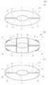
図4(A)(B)(C)は、清掃用保持具1に設けられる保持ヘッドの変形例を示す平面図である。 4A, 4 </ b> B, and 4 </ b> C are plan views illustrating modifications of the holding head provided in the cleaning holder 1.
図4(A)に示す保持ヘッド2Aは、保持爪12と保持爪13とを分離している切り込み11,11の支持体5側の端部に、前記切り込み11よりもX方向へ広がりを持つ拡開部11aが貫通して形成されている。よって、保持爪12と保持爪13とが互いに接近する方向へ弾性変形しやすくなっている。 The holding head 2 </ b> A shown in FIG. 4A has a spread in the X direction from the
図4(B)に示す保持ヘッド2Bは、保持爪12と保持爪13の外周に、それ自体が弾性変形可能なリブ状の凸部32が形成されている。保持空間26と27の内部に挿入されたときに、前記凸部32で側方接合線24と25が外側に向けて押されるようになり、清掃用品20が脱落しにくくなる。 In the holding head 2 </ b> B shown in FIG. 4B, rib-shaped
さらに図4(B)では、保持爪12,13の基部において、弾性保持体4にX方向に延びる薄肉部31,31が形成されて、保持爪12,13が変形しやすくなっている。 Further, in FIG. 4B,
図4(C)に示す保持ヘッド2Cは、保持爪12と保持爪13に、その対向方向に隆起する凸部33がそれぞれ形成されている。保持爪12と13が保持空間26,27に挿入されたときに、前記凸部33で、中央接合線23の部分が確実に挟持されるようになる。 In the holding head 2 </ b> C shown in FIG. 4C, the holding
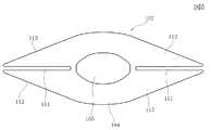
図5は本発明の第2の実施の形態の清掃用保持具の保持ヘッド102を示す平面図である。 FIG. 5 is a plan view showing the holding
この保持ヘッド102の弾性保持体104は、全体がほぼ菱形形状であり、切り込み111で分離された保持爪112と保持爪113はほぼ三角形である。また、支持体105は、長円形または多角形である。 The
図6は第3の実施の形態の保持ヘッド202を示す平面図である。
この保持ヘッド202は、弾性保持体204の両側部206,206、および支持体205の両側部207,207が、Y方向へ直線的に延びる部分を有している。そして、Y方向に向く両端部では、先部に向かって幅寸法が徐々に狭くなる保持爪212と保持爪213が形成されている。FIG. 6 is a plan view showing the holding
In the holding
図2に示す、弾性保持体4と支持体5が共に楕円形状の保持ヘッド2を有する清掃用保持具1を試作した。弾性保持体4はポリエステル系エラストマーで形成した。弾性保持体4の最大厚みは2mmであり、図7に基づいて測定した力Fが7.9Nであった。また支持体5はABS樹脂で形成し、清掃時の押圧力ではほとんど弾性変形しないものを用いた。 The cleaning holder 1 shown in FIG. 2 having the holding head 2 in which both the
清掃用品20は、Y方向の長さが280mmで、X方向の長さが150mm、平均厚みが3mmの不織布の積層体を使用した。 The cleaning
表1に示すように、保持ヘッド2の寸法L1とW1を変化させた。なお、支持体5はL2=100mm、W2=40mmとした。また、L3を65mmとした。 As shown in Table 1, the dimensions L1 and W1 of the holding head 2 were changed. The
フローリングの床面をX方向へ摺動させて清掃を行った。このときの安定性を○、△、×で評価した。比較例1では、保持ヘッド2がX方向へ反転し、実施例1では、保持ヘッド2がX方向へやや倒れそうな不安定さがあるが反転するには至らなかった。よってW1/L1は0.3以上が好ましく、さらに好ましくは0.33以上である。 The flooring of the flooring was slid in the X direction for cleaning. The stability at this time was evaluated by ○, Δ, and ×. In Comparative Example 1, the holding head 2 was reversed in the X direction, and in Example 1, the holding head 2 had an instability that seemed to fall slightly in the X direction, but did not reverse. Therefore, W1 / L1 is preferably 0.3 or more, and more preferably 0.33 or more.

次に、表2に示すように、図2に示す寸法L1,W1,L2,W2のそれぞれを変化させ、X方向へ向けて清掃を行った。安定性評価は、○、△、×とした。表2から保持ヘッド2の面積S1に対する支持体5の面積S2の比は、0.13以上で0.68以下が好ましく、さらには0.22以上であることが好ましい。 Next, as shown in Table 2, each of the dimensions L1, W1, L2, and W2 shown in FIG. 2 was changed, and cleaning was performed in the X direction. Stability evaluation was made into (circle), (triangle | delta), and x. From Table 2, the ratio of the area S2 of the
1 清掃用保持具
2 支持体
3 把持柄
4 弾性保持体
5 支持体
11 切り込み
12,13 保持爪DESCRIPTION OF SYMBOLS 1 Cleaning holder 2
Claims (9)
Translated fromJapanese前記保持ヘッドは、
弾性変形可能な材料で形成され、前記清掃用品が保持される弾性保持体と、
前記弾性体よりも硬質な材料で形成され、前記弾性保持体の一方の面に固定されており前記把持柄が連結される支持体とを有し、
前記弾性保持体と前記支持体とは共に、第1の方向の最大寸法が前記第1の方向と直交する第2の方向の最大寸法よりも大きく、
前記弾性保持体は、前記支持体の端部の外周よりも前記支持体の外側に向けて延出された延出部分を有し、
前記第1の方向において前記支持体の端部よりも前記支持体の外側に向けて延出された延出部分の寸法は40mm以上であり、前記第2の方向において前記支持体の端部よりも前記支持体の外側に向けて延出された延出部分の寸法よりも大きく、
前記第1の方向において前記支持体の端部から前記支持体の外側に向けて延出された延出部分には、前記支持体の端部に相当する位置まで切り込みが形成されることにより、複数の保持爪が形成されており、
前記弾性保持体は、前記保持爪によって前記清掃用品を保持することを特徴とする清掃用保持具。In a cleaning holder that holds a cleaning article and hasa holding headcoupled to a gripping handle ,
The holding head is
An elasticholder formed of an elastically deformable material andholding the cleaning article ;
A support thatis formed of a material harder than the elastic body, is fixed to one surface of the elastic holding body, andis connected to the grip handle ;
The elastic holding body and the support body both have a maximum dimension in a first direction larger than a maximum dimension in a second direction orthogonal to the first direction,
The elastic holding body has an extending portion that extends toward the outside of the support body from the outer periphery of the end portion of the support body,
In the first direction, the dimension of the extending portion extending toward the outside of the support body from the end portion of the support body is 40 mm or more, and in the second direction, from the end portion of the support body. Is larger than the dimension of the extended portion extending toward the outside of the support,
In the extending portion that extends from the end of the support toward the outside of the support in the first direction, a cut is formed to a position corresponding to the end of the support, A plurality of holding claws are formed,
The elastic holding body holds the cleaning article by the holding claws.
Priority Applications (1)
| Application Number | Priority Date | Filing Date | Title |
|---|---|---|---|
| JP2003325697AJP4344571B2 (en) | 2003-09-18 | 2003-09-18 | Cleaning tool |
Applications Claiming Priority (1)
| Application Number | Priority Date | Filing Date | Title |
|---|---|---|---|
| JP2003325697AJP4344571B2 (en) | 2003-09-18 | 2003-09-18 | Cleaning tool |
Publications (2)
| Publication Number | Publication Date |
|---|---|
| JP2005087506A JP2005087506A (en) | 2005-04-07 |
| JP4344571B2true JP4344571B2 (en) | 2009-10-14 |
Family
ID=34456076
Family Applications (1)
| Application Number | Title | Priority Date | Filing Date |
|---|---|---|---|
| JP2003325697AExpired - Fee RelatedJP4344571B2 (en) | 2003-09-18 | 2003-09-18 | Cleaning tool |
Country Status (1)
| Country | Link |
|---|---|
| JP (1) | JP4344571B2 (en) |
Families Citing this family (8)
| Publication number | Priority date | Publication date | Assignee | Title |
|---|---|---|---|---|
| US7891898B2 (en) | 2005-01-28 | 2011-02-22 | S.C. Johnson & Son, Inc. | Cleaning pad for wet, damp or dry cleaning |
| US7976235B2 (en) | 2005-01-28 | 2011-07-12 | S.C. Johnson & Son, Inc. | Cleaning kit including duster and spray |
| US7566671B2 (en) | 2005-01-28 | 2009-07-28 | S.C. Johnson & Son, Inc. | Cleaning or dusting pad |
| US7740412B2 (en) | 2005-01-28 | 2010-06-22 | S.C. Johnson & Son, Inc. | Method of cleaning using a device with a liquid reservoir and replaceable non-woven pad |
| US8893347B2 (en) | 2007-02-06 | 2014-11-25 | S.C. Johnson & Son, Inc. | Cleaning or dusting pad with attachment member holder |
| JP5959847B2 (en)* | 2011-12-22 | 2016-08-02 | 株式会社ダスキン | Torsional rotation type cleaning holder and cleaning tool |
| KR101578618B1 (en) | 2014-09-25 | 2015-12-17 | 김영철 | Water cleaner |
| JP6225146B2 (en)* | 2015-08-24 | 2017-11-01 | 株式会社無有 | Cleaning tool |
- 2003
- 2003-09-18JPJP2003325697Apatent/JP4344571B2/ennot_activeExpired - Fee Related
Also Published As
| Publication number | Publication date |
|---|---|
| JP2005087506A (en) | 2005-04-07 |
Similar Documents
| Publication | Publication Date | Title |
|---|---|---|
| US7779501B2 (en) | Mop having scrubbing area | |
| US8850649B2 (en) | Cleaning tool with upstanding stems and method of cleaning a surface | |
| US20090032059A1 (en) | Cleaning material and method of cleaning a surface | |
| EP1591053A1 (en) | Cleaning sheet | |
| EP0841870A1 (en) | Cleaning cloth and cleaning apparatus | |
| JP4001737B2 (en) | Cleaning tool | |
| JP4344571B2 (en) | Cleaning tool | |
| JP2002355211A (en) | Cleaner and methods of manufacture and use thereof | |
| JP5901910B2 (en) | Cleaning tool | |
| EP3094229B1 (en) | Cleaning tool | |
| JP4662454B2 (en) | Cleaning tool | |
| JP6563980B2 (en) | Cleaning tool | |
| JP6491695B2 (en) | Cleaning tool | |
| JP4037190B2 (en) | Cleaning tool | |
| JP3129712U (en) | Mop cleaning tool for floor | |
| JPH0956653A (en) | Wiper | |
| JP4027657B2 (en) | Cleaning tool | |
| JPH10243904A (en) | Mop | |
| JP4559877B2 (en) | Cleaning tool | |
| JPH08131388A (en) | Cleaning tool | |
| JP2005143616A (en) | Cleaning utensil | |
| JPH07327906A (en) | Cleaning tool | |
| JPH0810207A (en) | Cleaner | |
| JP2017000383A (en) | Cleaning tool |
Legal Events
| Date | Code | Title | Description |
|---|---|---|---|
| RD04 | Notification of resignation of power of attorney | Free format text:JAPANESE INTERMEDIATE CODE: A7424 Effective date:20060216 | |
| RD02 | Notification of acceptance of power of attorney | Free format text:JAPANESE INTERMEDIATE CODE: A7422 Effective date:20060206 | |
| A621 | Written request for application examination | Free format text:JAPANESE INTERMEDIATE CODE: A621 Effective date:20060721 | |
| A977 | Report on retrieval | Free format text:JAPANESE INTERMEDIATE CODE: A971007 Effective date:20081212 | |
| A131 | Notification of reasons for refusal | Free format text:JAPANESE INTERMEDIATE CODE: A131 Effective date:20090217 | |
| A521 | Written amendment | Free format text:JAPANESE INTERMEDIATE CODE: A523 Effective date:20090420 | |
| TRDD | Decision of grant or rejection written | ||
| A01 | Written decision to grant a patent or to grant a registration (utility model) | Free format text:JAPANESE INTERMEDIATE CODE: A01 Effective date:20090616 | |
| A01 | Written decision to grant a patent or to grant a registration (utility model) | Free format text:JAPANESE INTERMEDIATE CODE: A01 | |
| A61 | First payment of annual fees (during grant procedure) | Free format text:JAPANESE INTERMEDIATE CODE: A61 Effective date:20090713 | |
| FPAY | Renewal fee payment (event date is renewal date of database) | Free format text:PAYMENT UNTIL: 20120717 Year of fee payment:3 | |
| R150 | Certificate of patent or registration of utility model | Free format text:JAPANESE INTERMEDIATE CODE: R150 | |
| FPAY | Renewal fee payment (event date is renewal date of database) | Free format text:PAYMENT UNTIL: 20120717 Year of fee payment:3 | |
| FPAY | Renewal fee payment (event date is renewal date of database) | Free format text:PAYMENT UNTIL: 20130717 Year of fee payment:4 | |
| R250 | Receipt of annual fees | Free format text:JAPANESE INTERMEDIATE CODE: R250 | |
| RD02 | Notification of acceptance of power of attorney | Free format text:JAPANESE INTERMEDIATE CODE: R3D02 | |
| R250 | Receipt of annual fees | Free format text:JAPANESE INTERMEDIATE CODE: R250 | |
| R250 | Receipt of annual fees | Free format text:JAPANESE INTERMEDIATE CODE: R250 | |
| R250 | Receipt of annual fees | Free format text:JAPANESE INTERMEDIATE CODE: R250 | |
| LAPS | Cancellation because of no payment of annual fees |