JP4343271B2 - Method for forming a polycrystalline layer of superhard material - Google Patents
Method for forming a polycrystalline layer of superhard materialDownload PDFInfo
- Publication number
- JP4343271B2 JP4343271B2JP51144797AJP51144797AJP4343271B2JP 4343271 B2JP4343271 B2JP 4343271B2JP 51144797 AJP51144797 AJP 51144797AJP 51144797 AJP51144797 AJP 51144797AJP 4343271 B2JP4343271 B2JP 4343271B2
- Authority
- JP
- Japan
- Prior art keywords
- layer
- particles
- high shear
- cemented carbide
- polycrystalline
- Prior art date
- Legal status (The legal status is an assumption and is not a legal conclusion. Google has not performed a legal analysis and makes no representation as to the accuracy of the status listed.)
- Expired - Fee Related
Links
- 239000000463materialSubstances0.000titleclaimsdescription108
- 238000000034methodMethods0.000titleclaimsdescription66
- 239000002245particleSubstances0.000claimsdescription129
- 239000010432diamondSubstances0.000claimsdescription98
- 229910003460diamondInorganic materials0.000claimsdescription97
- 238000005056compactionMethods0.000claimsdescription58
- 239000011230binding agentSubstances0.000claimsdescription49
- 230000008569processEffects0.000claimsdescription42
- OKTJSMMVPCPJKN-UHFFFAOYSA-NCarbonChemical compound[C]OKTJSMMVPCPJKN-UHFFFAOYSA-N0.000claimsdescription36
- 229910052799carbonInorganic materials0.000claimsdescription33
- 239000000758substrateSubstances0.000claimsdescription27
- 238000010438heat treatmentMethods0.000claimsdescription23
- 239000000203mixtureSubstances0.000claimsdescription23
- 238000009826distributionMethods0.000claimsdescription18
- 229910052751metalInorganic materials0.000claimsdescription18
- 239000002184metalSubstances0.000claimsdescription18
- 238000004519manufacturing processMethods0.000claimsdescription14
- 238000007596consolidation processMethods0.000claimsdescription8
- 230000007704transitionEffects0.000claimsdescription8
- 238000012545processingMethods0.000claimsdescription6
- 239000013078crystalSubstances0.000description31
- PZNSFCLAULLKQX-UHFFFAOYSA-NBoron nitrideChemical compoundN#BPZNSFCLAULLKQX-UHFFFAOYSA-N0.000description28
- 229910052582BNInorganic materials0.000description26
- UONOETXJSWQNOL-UHFFFAOYSA-Ntungsten carbideChemical compound[W+]#[C-]UONOETXJSWQNOL-UHFFFAOYSA-N0.000description21
- 239000010941cobaltSubstances0.000description15
- 229910017052cobaltInorganic materials0.000description15
- GUTLYIVDDKVIGB-UHFFFAOYSA-Ncobalt atomChemical compound[Co]GUTLYIVDDKVIGB-UHFFFAOYSA-N0.000description15
- 239000000843powderSubstances0.000description14
- 238000005520cutting processMethods0.000description13
- 238000005238degreasingMethods0.000description13
- 238000012360testing methodMethods0.000description11
- ZWEHNKRNPOVVGH-UHFFFAOYSA-N2-ButanoneChemical compoundCCC(C)=OZWEHNKRNPOVVGH-UHFFFAOYSA-N0.000description9
- QVGXLLKOCUKJST-UHFFFAOYSA-Natomic oxygenChemical compound[O]QVGXLLKOCUKJST-UHFFFAOYSA-N0.000description9
- 239000002131composite materialSubstances0.000description9
- 239000001301oxygenSubstances0.000description9
- 229910052760oxygenInorganic materials0.000description9
- 239000011435rockSubstances0.000description9
- QGZKDVFQNNGYKY-UHFFFAOYSA-NAmmoniaChemical compoundNQGZKDVFQNNGYKY-UHFFFAOYSA-N0.000description8
- 238000006392deoxygenation reactionMethods0.000description7
- 239000010438graniteSubstances0.000description7
- 238000001953recrystallisationMethods0.000description6
- 229910002804graphiteInorganic materials0.000description5
- 239000010439graphiteSubstances0.000description5
- 230000001965increasing effectEffects0.000description5
- 230000018984masticationEffects0.000description5
- 238000010077masticationMethods0.000description5
- 239000011368organic materialSubstances0.000description5
- 238000012856packingMethods0.000description5
- 239000004014plasticizerSubstances0.000description5
- 239000002904solventSubstances0.000description5
- 238000010345tape castingMethods0.000description5
- LFQSCWFLJHTTHZ-UHFFFAOYSA-NEthanolChemical compoundCCOLFQSCWFLJHTTHZ-UHFFFAOYSA-N0.000description4
- 229910021529ammoniaInorganic materials0.000description4
- 230000015572biosynthetic processEffects0.000description4
- 238000005336crackingMethods0.000description4
- XLYOFNOQVPJJNP-UHFFFAOYSA-NwaterSubstancesOXLYOFNOQVPJJNP-UHFFFAOYSA-N0.000description4
- CSCPPACGZOOCGX-UHFFFAOYSA-NAcetoneChemical compoundCC(C)=OCSCPPACGZOOCGX-UHFFFAOYSA-N0.000description3
- YXFVVABEGXRONW-UHFFFAOYSA-NTolueneChemical compoundCC1=CC=CC=C1YXFVVABEGXRONW-UHFFFAOYSA-N0.000description3
- 239000000919ceramicSubstances0.000description3
- 239000011195cermetSubstances0.000description3
- 239000010419fine particleSubstances0.000description3
- 238000002156mixingMethods0.000description3
- 239000003960organic solventSubstances0.000description3
- -1polypropylene carbonatePolymers0.000description3
- 238000003825pressingMethods0.000description3
- 239000000047productSubstances0.000description3
- 238000005245sinteringMethods0.000description3
- 239000000126substanceSubstances0.000description3
- 239000011800void materialSubstances0.000description3
- XKRFYHLGVUSROY-UHFFFAOYSA-NArgonChemical compound[Ar]XKRFYHLGVUSROY-UHFFFAOYSA-N0.000description2
- IRIAEXORFWYRCZ-UHFFFAOYSA-NButylbenzyl phthalateChemical compoundCCCCOC(=O)C1=CC=CC=C1C(=O)OCC1=CC=CC=C1IRIAEXORFWYRCZ-UHFFFAOYSA-N0.000description2
- PEDCQBHIVMGVHV-UHFFFAOYSA-NGlycerineChemical compoundOCC(O)COPEDCQBHIVMGVHV-UHFFFAOYSA-N0.000description2
- UFHFLCQGNIYNRP-UHFFFAOYSA-NHydrogenChemical compound[H][H]UFHFLCQGNIYNRP-UHFFFAOYSA-N0.000description2
- 239000000853adhesiveSubstances0.000description2
- 230000001070adhesive effectEffects0.000description2
- 229910003481amorphous carbonInorganic materials0.000description2
- 239000003125aqueous solventSubstances0.000description2
- 150000001721carbonChemical group0.000description2
- 125000004432carbon atomChemical groupC*0.000description2
- 230000008859changeEffects0.000description2
- 239000011248coating agentSubstances0.000description2
- 238000000576coating methodMethods0.000description2
- 238000000354decomposition reactionMethods0.000description2
- 230000032798delaminationEffects0.000description2
- 230000001627detrimental effectEffects0.000description2
- DOIRQSBPFJWKBE-UHFFFAOYSA-Ndibutyl phthalateChemical compoundCCCCOC(=O)C1=CC=CC=C1C(=O)OCCCCDOIRQSBPFJWKBE-UHFFFAOYSA-N0.000description2
- 238000004090dissolutionMethods0.000description2
- 235000019441ethanolNutrition0.000description2
- 238000011156evaluationMethods0.000description2
- 239000007789gasSubstances0.000description2
- 238000009499grossingMethods0.000description2
- 239000001257hydrogenSubstances0.000description2
- 229910052739hydrogenInorganic materials0.000description2
- 125000002887hydroxy groupChemical group[H]O*0.000description2
- 230000006872improvementEffects0.000description2
- 238000005461lubricationMethods0.000description2
- VNWKTOKETHGBQD-UHFFFAOYSA-NmethaneChemical compoundCVNWKTOKETHGBQD-UHFFFAOYSA-N0.000description2
- 238000003801millingMethods0.000description2
- 230000003647oxidationEffects0.000description2
- 238000007254oxidation reactionMethods0.000description2
- 239000012188paraffin waxSubstances0.000description2
- 229920000379polypropylene carbonatePolymers0.000description2
- 230000009467reductionEffects0.000description2
- 238000005979thermal decomposition reactionMethods0.000description2
- 238000009827uniform distributionMethods0.000description2
- 229920002554vinyl polymerPolymers0.000description2
- 239000003039volatile agentSubstances0.000description2
- QMMJWQMCMRUYTG-UHFFFAOYSA-N1,2,4,5-tetrachloro-3-(trifluoromethyl)benzeneChemical compoundFC(F)(F)C1=C(Cl)C(Cl)=CC(Cl)=C1ClQMMJWQMCMRUYTG-UHFFFAOYSA-N0.000description1
- MLRVZFYXUZQSRU-UHFFFAOYSA-N1-chlorohexaneChemical compoundCCCCCCClMLRVZFYXUZQSRU-UHFFFAOYSA-N0.000description1
- OTMSDBZUPAUEDD-UHFFFAOYSA-NEthaneChemical compoundCCOTMSDBZUPAUEDD-UHFFFAOYSA-N0.000description1
- 239000001856Ethyl celluloseSubstances0.000description1
- ZZSNKZQZMQGXPY-UHFFFAOYSA-NEthyl celluloseChemical compoundCCOCC1OC(OC)C(OCC)C(OCC)C1OC1C(O)C(O)C(OC)C(CO)O1ZZSNKZQZMQGXPY-UHFFFAOYSA-N0.000description1
- WSFSSNUMVMOOMR-UHFFFAOYSA-NFormaldehydeChemical compoundO=CWSFSSNUMVMOOMR-UHFFFAOYSA-N0.000description1
- NTIZESTWPVYFNL-UHFFFAOYSA-NMethyl isobutyl ketoneChemical compoundCC(C)CC(C)=ONTIZESTWPVYFNL-UHFFFAOYSA-N0.000description1
- CTQNGGLPUBDAKN-UHFFFAOYSA-NO-XyleneChemical compoundCC1=CC=CC=C1CCTQNGGLPUBDAKN-UHFFFAOYSA-N0.000description1
- 239000004698PolyethyleneSubstances0.000description1
- 239000002202Polyethylene glycolSubstances0.000description1
- 229920001756Polyvinyl chloride acetatePolymers0.000description1
- 238000001069Raman spectroscopyMethods0.000description1
- XSTXAVWGXDQKEL-UHFFFAOYSA-NTrichloroethyleneChemical groupClC=C(Cl)ClXSTXAVWGXDQKEL-UHFFFAOYSA-N0.000description1
- 239000012736aqueous mediumSubstances0.000description1
- 229910052786argonInorganic materials0.000description1
- 230000000712assemblyEffects0.000description1
- 238000000429assemblyMethods0.000description1
- 238000000498ball millingMethods0.000description1
- 230000009286beneficial effectEffects0.000description1
- 125000004063butyryl groupChemical groupO=C([*])C([H])([H])C([H])([H])C([H])([H])[H]0.000description1
- 230000015556catabolic processEffects0.000description1
- 238000005524ceramic coatingMethods0.000description1
- 239000003795chemical substances by applicationSubstances0.000description1
- 238000005229chemical vapour depositionMethods0.000description1
- 150000008280chlorinated hydrocarbonsChemical class0.000description1
- 239000013065commercial productSubstances0.000description1
- 230000006378damageEffects0.000description1
- 239000007857degradation productSubstances0.000description1
- 238000006731degradation reactionMethods0.000description1
- 230000003635deoxygenating effectEffects0.000description1
- 229960002380dibutyl phthalateDrugs0.000description1
- WYACBZDAHNBPPB-UHFFFAOYSA-Ndiethyl oxalateChemical compoundCCOC(=O)C(=O)OCCWYACBZDAHNBPPB-UHFFFAOYSA-N0.000description1
- 239000002270dispersing agentSubstances0.000description1
- 239000006185dispersionSubstances0.000description1
- 230000000694effectsEffects0.000description1
- 238000000635electron micrographMethods0.000description1
- 238000005516engineering processMethods0.000description1
- 230000002708enhancing effectEffects0.000description1
- 229920001249ethyl cellulosePolymers0.000description1
- 235000019325ethyl celluloseNutrition0.000description1
- 238000001704evaporationMethods0.000description1
- 230000008020evaporationEffects0.000description1
- 229960004279formaldehydeDrugs0.000description1
- 235000019256formaldehydeNutrition0.000description1
- 235000011187glycerolNutrition0.000description1
- 150000002334glycolsChemical class0.000description1
- 230000005484gravityEffects0.000description1
- 239000003779heat-resistant materialSubstances0.000description1
- 238000009863impact testMethods0.000description1
- 239000007788liquidSubstances0.000description1
- 238000011068loading methodMethods0.000description1
- 125000002496methyl groupChemical group[H]C([H])([H])*0.000description1
- 238000012986modificationMethods0.000description1
- 230000004048modificationEffects0.000description1
- 229910052758niobiumInorganic materials0.000description1
- 239000010955niobiumSubstances0.000description1
- GUCVJGMIXFAOAE-UHFFFAOYSA-Nniobium atomChemical compound[Nb]GUCVJGMIXFAOAE-UHFFFAOYSA-N0.000description1
- XNGIFLGASWRNHJ-UHFFFAOYSA-Nphthalic acidChemical classOC(=O)C1=CC=CC=C1C(O)=OXNGIFLGASWRNHJ-UHFFFAOYSA-N0.000description1
- 238000005498polishingMethods0.000description1
- 229920001483poly(ethyl methacrylate) polymerPolymers0.000description1
- 229920003229poly(methyl methacrylate)Polymers0.000description1
- 229920000573polyethylenePolymers0.000description1
- 229920001223polyethylene glycolPolymers0.000description1
- 239000004926polymethyl methacrylateSubstances0.000description1
- 230000001737promoting effectEffects0.000description1
- 229910052903pyrophylliteInorganic materials0.000description1
- 239000002994raw materialSubstances0.000description1
- 239000003870refractory metalSubstances0.000description1
- 239000013557residual solventSubstances0.000description1
- 150000003839saltsChemical class0.000description1
- 238000007789sealingMethods0.000description1
- 239000002002slurrySubstances0.000description1
- 239000007787solidSubstances0.000description1
- 238000004901spallingMethods0.000description1
- 239000000725suspensionSubstances0.000description1
- 238000012546transferMethods0.000description1
- UBOXGVDOUJQMTN-UHFFFAOYSA-NtrichloroethyleneNatural productsClCC(Cl)ClUBOXGVDOUJQMTN-UHFFFAOYSA-N0.000description1
- ZIBGPFATKBEMQZ-UHFFFAOYSA-Ntriethylene glycolChemical compoundOCCOCCOCCOZIBGPFATKBEMQZ-UHFFFAOYSA-N0.000description1
- 239000000080wetting agentSubstances0.000description1
- 238000004804windingMethods0.000description1
- 230000037303wrinklesEffects0.000description1
- 239000008096xyleneSubstances0.000description1
Images


Classifications
- B—PERFORMING OPERATIONS; TRANSPORTING
- B24—GRINDING; POLISHING
- B24D—TOOLS FOR GRINDING, BUFFING OR SHARPENING
- B24D18/00—Manufacture of grinding tools or other grinding devices, e.g. wheels, not otherwise provided for
- B24D18/0009—Manufacture of grinding tools or other grinding devices, e.g. wheels, not otherwise provided for using moulds or presses
- B—PERFORMING OPERATIONS; TRANSPORTING
- B24—GRINDING; POLISHING
- B24D—TOOLS FOR GRINDING, BUFFING OR SHARPENING
- B24D3/00—Physical features of abrasive bodies, or sheets, e.g. abrasive surfaces of special nature; Abrasive bodies or sheets characterised by their constituents
- B24D3/02—Physical features of abrasive bodies, or sheets, e.g. abrasive surfaces of special nature; Abrasive bodies or sheets characterised by their constituents the constituent being used as bonding agent
- B24D3/04—Physical features of abrasive bodies, or sheets, e.g. abrasive surfaces of special nature; Abrasive bodies or sheets characterised by their constituents the constituent being used as bonding agent and being essentially inorganic
- B24D3/06—Physical features of abrasive bodies, or sheets, e.g. abrasive surfaces of special nature; Abrasive bodies or sheets characterised by their constituents the constituent being used as bonding agent and being essentially inorganic metallic or mixture of metals with ceramic materials, e.g. hard metals, "cermets", cements
- B—PERFORMING OPERATIONS; TRANSPORTING
- B24—GRINDING; POLISHING
- B24D—TOOLS FOR GRINDING, BUFFING OR SHARPENING
- B24D3/00—Physical features of abrasive bodies, or sheets, e.g. abrasive surfaces of special nature; Abrasive bodies or sheets characterised by their constituents
- B24D3/02—Physical features of abrasive bodies, or sheets, e.g. abrasive surfaces of special nature; Abrasive bodies or sheets characterised by their constituents the constituent being used as bonding agent
- B24D3/20—Physical features of abrasive bodies, or sheets, e.g. abrasive surfaces of special nature; Abrasive bodies or sheets characterised by their constituents the constituent being used as bonding agent and being essentially organic
- B24D3/28—Resins or natural or synthetic macromolecular compounds
- Y—GENERAL TAGGING OF NEW TECHNOLOGICAL DEVELOPMENTS; GENERAL TAGGING OF CROSS-SECTIONAL TECHNOLOGIES SPANNING OVER SEVERAL SECTIONS OF THE IPC; TECHNICAL SUBJECTS COVERED BY FORMER USPC CROSS-REFERENCE ART COLLECTIONS [XRACs] AND DIGESTS
- Y10—TECHNICAL SUBJECTS COVERED BY FORMER USPC
- Y10S—TECHNICAL SUBJECTS COVERED BY FORMER USPC CROSS-REFERENCE ART COLLECTIONS [XRACs] AND DIGESTS
- Y10S76/00—Metal tools and implements, making
- Y10S76/11—Tungsten and tungsten carbide
- Y—GENERAL TAGGING OF NEW TECHNOLOGICAL DEVELOPMENTS; GENERAL TAGGING OF CROSS-SECTIONAL TECHNOLOGIES SPANNING OVER SEVERAL SECTIONS OF THE IPC; TECHNICAL SUBJECTS COVERED BY FORMER USPC CROSS-REFERENCE ART COLLECTIONS [XRACs] AND DIGESTS
- Y10—TECHNICAL SUBJECTS COVERED BY FORMER USPC
- Y10S—TECHNICAL SUBJECTS COVERED BY FORMER USPC CROSS-REFERENCE ART COLLECTIONS [XRACs] AND DIGESTS
- Y10S76/00—Metal tools and implements, making
- Y10S76/12—Diamond tools
- Y—GENERAL TAGGING OF NEW TECHNOLOGICAL DEVELOPMENTS; GENERAL TAGGING OF CROSS-SECTIONAL TECHNOLOGIES SPANNING OVER SEVERAL SECTIONS OF THE IPC; TECHNICAL SUBJECTS COVERED BY FORMER USPC CROSS-REFERENCE ART COLLECTIONS [XRACs] AND DIGESTS
- Y10—TECHNICAL SUBJECTS COVERED BY FORMER USPC
- Y10T—TECHNICAL SUBJECTS COVERED BY FORMER US CLASSIFICATION
- Y10T156/00—Adhesive bonding and miscellaneous chemical manufacture
- Y10T156/10—Methods of surface bonding and/or assembly therefor
- Y10T156/1052—Methods of surface bonding and/or assembly therefor with cutting, punching, tearing or severing
- Y10T156/1062—Prior to assembly
- Y10T156/1067—Continuous longitudinal slitting
- Y—GENERAL TAGGING OF NEW TECHNOLOGICAL DEVELOPMENTS; GENERAL TAGGING OF CROSS-SECTIONAL TECHNOLOGIES SPANNING OVER SEVERAL SECTIONS OF THE IPC; TECHNICAL SUBJECTS COVERED BY FORMER USPC CROSS-REFERENCE ART COLLECTIONS [XRACs] AND DIGESTS
- Y10—TECHNICAL SUBJECTS COVERED BY FORMER USPC
- Y10T—TECHNICAL SUBJECTS COVERED BY FORMER US CLASSIFICATION
- Y10T156/00—Adhesive bonding and miscellaneous chemical manufacture
- Y10T156/10—Methods of surface bonding and/or assembly therefor
- Y10T156/1052—Methods of surface bonding and/or assembly therefor with cutting, punching, tearing or severing
- Y10T156/1062—Prior to assembly
- Y10T156/1075—Prior to assembly of plural laminae from single stock and assembling to each other or to additional lamina
Landscapes
- Engineering & Computer Science (AREA)
- Mechanical Engineering (AREA)
- Chemical & Material Sciences (AREA)
- Ceramic Engineering (AREA)
- Inorganic Chemistry (AREA)
- Manufacturing & Machinery (AREA)
- Polishing Bodies And Polishing Tools (AREA)
- Cutting Tools, Boring Holders, And Turrets (AREA)
- Laminated Bodies (AREA)
Description
Translated fromJapanese発明の分野
本発明は、広くは、多結晶ダイヤモンド複合体に関する。
より詳しくは、本発明は、従来技術で知られる複合体を大きく改良した多結晶ダイヤモンド(PCD)又は立方晶窒化ホウ素(PCBN)複合体の製造方法に関する。本方法は、高い剪断圧密技術と高温高圧処理を併用し、高強度の密着性複合体を製造する。
背景
焼結されて焼結炭化物基材に結合された超硬粒子からなる多結晶ダイヤモンド複合体は、切削工具やドリルビットカッターなどの工業的によく知られた用途を有する。最も多く市販されている多結晶ダイヤモンド又は立方晶窒化ホウ素複合体は、米国特許第3745623号の教示にしたがって製造され、例えば、割合に少量の超硬粒子が、焼結炭化タングステン基材の上に薄い層(約0.5〜1.3mm)として焼結される。
一般的に言って、複合体の製造プロセスは、炭化タングステン粒子がコバルトを用いて互いに焼結された焼結炭化タングステン体を使用する。炭化物体は、ダイヤモンド粒子層に隣接して配置され、この組み合わせが、ダイヤモンドが熱力学的に安定な圧力と高温に曝される。これにより、焼結炭化タングステンの表面上で多結晶ダイヤモンドの再結晶と生成が起きる。ダイヤモンド結晶の層は、炭化タングステン粒子及び/又は少量のコバルトを含むことがある。コバルトは、多結晶ダイヤモンドの生成を促進し、ダイヤモンドの層に存在しなくしも、コバルトは焼結炭化タングステン基材から侵入することができる。
この方法は多くの用途に満足できるが、より高い耐衝撃性、均一性、製造容易性を複合体に提供することは常に望まれている。また、多結晶ダイヤモンド層を形成するのに実施できるその方法は、その層を非平面に配置する場合、困難である。
本発明は、高圧・高温技術を併用した本願では「高剪断圧密」と称する技術とプロセスを用いて多結晶ダイヤモンド複合体を製造する方法に関する。高圧高温プロセスとは、ダイヤモンド又は立方晶窒化ホウ素が熱力学的に安定な十分に高い圧力と温度で処理することを言う。このプロセスは、場合により、超高圧プレスで行われることを指称する。圧力は一般に65キロバール以上であり、温度は2000℃を上回ることがある。このプロセス部分は一般的である。
プロセスの一部は「テープキャスティング」として知られているものに共通する。テープキャスティングは、セラミックコーティング、基板、多層構造を形成するためにエレクトロニクス工業で最も慣用されている。高圧高温のダイヤモンドテープ注型プロセスを用い、金属炭化物基材の上の予備成形された平面又は非平面に薄い多結晶ダイヤモンド層を直接結合させるプロセスは、米国特許出願第08/026890号に記載されている。
このプロセスにおいて、微細なセラミック又はサーメット粉末が消失性有機バインダーと混合される。この混合物は、最適な粘度まで混合・粉砕され、次いで所望の厚さのシート(テープ)に注型又は圧延される。テープが乾燥され、水又は有機溶媒が除去される。乾燥後のテープは可撓性があり、この状態で取り扱われて、消失性バインダーを用いて対応する基材の形状の一致させるに必要な形状に切断するのに十分な強度がある。テープ/基材のアセンブリーは、最初に、消失性接着剤及び/又はバインダー材料を逃散させるのに十分な高温まで真空炉の中で加熱される。次いでその温度が、セラミック又はサーメット粉末が互いに及び/又は基材に融合するレベルまで高められ、それにより、基材に結合した非常に均一な連続的セラミック又はサーメットコーティングが生成する。
改良された耐衝撃性や靱性、耐磨耗性、均一性、製造容易性を備えた多結晶ダイヤモンド又は立方晶窒化ホウ素複合体を提供することが望まれている。
発明の要旨
本発明は、焼結金属炭化物基材に結合した多結晶超硬層を形成する改良された方法を提供する。ダイヤモンド又は立方晶窒化ホウ素を含む緻密な高剪断圧密材料の層が、金属炭化物基材に隣接して配置される。超硬材料の粒子は、高い剪断圧密のおかげで角張っているのではなく丸みがついている。高剪断圧密材料の中の揮発物は、例えば950℃の高温で分解し、炭化物基材上の超硬材料粒子の層の中に残留炭素を残存させる。この基材と層のアセンブリーは、次いで高温高圧に曝され、それにより、超硬粒子が互いに焼結し、金属炭化物基材に結合した多結晶超硬層が生成する。また、高剪断圧密材料の層は、層の全体にわたって均一に分配された大きめの粒子と小さめの粒子を含む粒子サイズ分布を特徴とする。
【図面の簡単な説明】
図1は、高剪断圧密材料のシートの横断面図である。
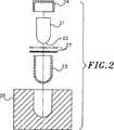
図2は、図3に示された本発明の態様を作成するのに使用された構成部分の部分的な分解組立図である。
図3は、本発明によって得られたロックビットインサートの横断面図である。
図4は、図2のアセンブリーに使用された高剪断圧密材料のプレフォームの平面図である。
図5は、高剪断圧密材料を作成するために使用された超硬材料の粒子サイズ分布のグラフである。
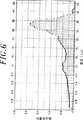
図6は、高剪断圧密材料シートに成形された後の超硬材料の粒子サイズ分布のグラフである。
図7は、高剪断圧密材料シートの作成の際の過剰な素練りの後の、超硬材料の粒子サイズ分布のグラフである。
図8は、端部に多結晶ダイヤモンド層を有するロックビットインサートの縦断面図である。
詳細な説明
図1は、文献「Ragan Technologies, 11696 Sorrento Valley Road, Suite D, San Diego, California 921121」にしたがって得られた高剪断圧密材料20のシートである。高剪断圧密材料は、ダイヤモンド又は立方晶窒化ホウ素のような超硬材料の粒子、及びポリプロピレンカーボネートのような有機バインダー(及び場合によりメチルエチルケトン(MEK)のような残存溶媒)を含んでなる。高剪断圧密材料のシートは、多数ローラープロセスで調製される。例えば、多数ローラーの高剪断圧密プロセスにおける第1ローラー処理は、厚さ約0.25mmのシートを作成する。次いでこのシートは、それ自身に重ねられて2回目のローラー処理に供され、厚さ約0.45mmのシートを作成する。このシートは、多層の厚さを有するように、折り曲げられ又は切断されて重ねられる。
この圧密プロセスは、テープに高剪断を生じさせ、超硬粒子の広範囲な素練り(mastication)をもたらし、それらを割らずにコーナーやエッジを欠落させ、割合に小さい体積の粒子をその場所で生成させる。また、このプロセスは、粒子の徹底した混合をもたらし、高剪断圧密材料の全体にわたって大きめの粒子と小さめの粒子の均一な分布を生じさせる。この破壊は、粒子の実質的な数を増やすことなく、粒子に丸みをつける。
また、ローラー処理プロセスの間の高剪断は、高密度のシート、即ち、約2.5〜2.7g/cm3、好ましくは約2.6±0.05g/cm3のシートを生成する。この密度は、約80重量%のダイヤモンド結晶と20重量%の有機バインダーを有するシートとして特徴づけられる。場合により、シート中に炭化タングステン粒子及び/又はコバルトを含めることが望ましい。また、場合により、「ドレープ適性(drapability)」を高めるため、シート中により高い割合のバインダーとより低い割合のダイヤモンド粒子が存在してもよい。シートの所望の密度は比例的に調節され、対応したシートが得られる。
高剪断圧密材料のシートは、高いグリーン密度を特徴とし、加熱時の低い収縮をもたらす。例えば、平坦な表面の基材に使用されるシートは、理論密度の約70%の密度を有する。ローラープロセスによって得られるシートの高い密度と粒子の均一な分布は、予備焼結の加熱工程時の少ない収縮と、非常に均一な粒子分布を有する予備焼結後の超硬層を生じさせ易く、これが、高圧高温プロセスで得られる結果を改良する。
図2は、多結晶ダイヤモンド複合物品を製造するために使用される構成部分の分解図であり、この場合、ロックビット用のインサートである。このようなインサートは、ロックビットインサートに通常使用されるいろいろな一般的形状を有する焼結炭化タングステン体21を備える。このプロセスを説明するのに適当な例としての代表的なインサートは、半球形の端部22を備えた円筒体を有する。本発明の実施によって得られる「改良されたインサート」は、半球端部の上に多結晶ダイヤモンドの層を有する。
改良されたインサートは、インサートの形状に対応する内側形状を有するカップ23の中で作成される。このカップのキャップ24は、一般に、ニオブその他の耐熱材料からなる。カップは、カップの外側に対応するキャビティを有する一時的なダイ又はジグ26の中に配置される。ダイヤモンド結晶などを含む高剪断圧密シートの1枚以上の層27が、カップの半球状端部の中に配置される。具体的には、カップは層を成形する型として役立つ。
このような層の各々は、高剪断圧密材料のシートを切断したプレフォームを含んでなる。インサートの半球状端部にフィットする図4に示したような例示のプレフォームは、周囲から中心の方に延びる4つのほぼV形のノッチ28を有する円形ディスクである。ノッチは、過度に折り曲げたり皺や二重の厚さを生じさせずに、平坦なプレフォームを曲げて半球形のカップの中に入れることを可能にさせる。
次に、インサート、又はインサートと同じ形状を有するパンチがカップの中に押し込められ、高剪断圧密材料の層を滑らかにし、カップの端部で実質的に均一な厚さにする。軸対称のインサートなどを作成する場合、高剪断圧密材料を滑らかにするのを助長するため、このようなパンチを回転させてもよい。多層の高剪断圧密材料がカップの中で用いられる場合、それらは1枚ずつ導入し、個々に滑らかにすることが好ましい。カップの中で材料の増加した厚さに対応するため、順次の層に対して若干異なるパンチ形状が使用されてもよい。
材料が滑らかにされた後、インサート体がカップの中に入れられ(平滑化のために既に存在していなければ)、ダイ26からカップが取り出される。
次いで高剪断圧密材料中の有機バインダーが除去され、ダイヤモンド結晶がカップの中に残される。好ましくは、有機材料は、インサートがカップの中に入れられた後に除去されるが、そうではなくて、インサートがカップの中に入れられる前に有機材料が除去されてもよい。
1枚以上の高剪断圧密層中の有機材料は、そのアセンブリーを約1025℃の温度に真空中で加熱することにより「脱脂」される。加熱は、アルゴンやアンモニアのような不活性又は還元性ガスの中で行われてもよい。後者は、インサートその他の物体に施される超硬材料が立方晶窒化ホウ素の場合に有益である。
高剪断圧密材料から有機バインダーを除去する一般的な脱脂プロセスは、300℃〜600℃のレベルの温度に加熱することである。驚くべきことに、少なくとも950℃の温度に加熱することにより、高温プロセスによる顕著に高められた結果が得られることが見出されている。この理由は完全には分かっていないが、改良された結果は、バインダー材料の熱分解と残存炭素による脱酸素によるものと考えられる。
超硬粒子を含む高剪断圧密材料を前処理するための温度は950℃以上が好ましい。例えば、950℃の真空中で数時間加熱するのがダイヤモンド含有材料にとって適切である。1025℃の温度でのより短い時間もまた良好な結果を与える。立方晶窒化ホウ素にはより高い温度が使用されてよく、立方晶窒化ホウ素の化学量論を維持して表面酸素を除去するのに、立方晶窒化ホウ素をアンモニア中で加熱することが望ましいことがある。また、加熱速度が問題になり得ることが経験されており、低い加熱速度が望ましいことがある。バインダー中の揮発性物質の蒸発が、高い加熱速度で微細な「ふくれ(blistering)」を生じさせ得ると考えられる。脱脂中に発生する揮発物が高剪断圧密材料が容易に逃散せず、離層を生じさせることもある。約5℃/分の加熱速度に比較すると、約2℃/分の加熱速度で顕著な改良結果が得られる。
代表的な脱脂サイクル、即ち、加熱によるシート材料からのバインダーの除去は、500℃まで2℃/分の加熱速度を有する。温度は500℃で2時間保持される。次いで5℃/分以下の加熱速度で950℃まで加熱が再開される。温度が950℃で6時間保持され、次いで2℃/分で降温される。
この加熱と約500℃の温度での保持は通常の脱脂と同様である。バインダー中の有機材料の分解が、超硬材料粒子の層の中を通る分解生成物の逃散速度よりも速くないように、遅い加熱が望ましい。そうしなければ離層が生じることがある。
脱脂の後、高剪断圧密プロセスの前又は途中に生じた酸化物を還元させるため、超硬材料の層がかなり高い温度まで加熱される。酸化物の還元は、有機バインダー材料の分解によって生じた粒子上の残存炭素によって促進される。ダイヤモンドについて、少なくとも950℃の温度が重要である。立方晶窒化ホウ素についてはより高い温度が使用されることができる。立方晶窒化ホウ素粒子の上の炭素が同様に脱酸素を促進させる。
有機バインダーが高剪断圧密材料から除去され後、耐熱金属のキャップ24が、カップ23の周りと開口端部の上に配置される。キャップの内側は、カップの外側にかなりぴったりとフィットする。次いでこのアセンブリーはダイに通し、キャップをカップの外側にきつくかみ合わせる「スエージ加工」を施し、得られた「カン(can)」の内側の焼結炭化物体とダイヤモンド結晶層を有効にシールする。こうしたアセンブリーは、塩で囲まれたグラファイトスリーブのヒーターの中に配置され、そのヒーターは、パイロフィライト又は同様な材料のブロックの中に配置される。これは、端部に多結晶ダイヤモンド層を備えた改良形インサートを作成するため、高圧高温プレスの中に配置される通常のアセンブリーである。
炭化物体とダイヤモンド粒子層を有するアセンブリーは、超高圧プレスの中に配置され、35キロバールを上回る65キロバールにも及ぶダイヤモンドが熱力学的に安定な圧力まで加圧される。このような高圧を維持しながら、プレスの中の材料は、多結晶ダイヤモンドが生成するまでの短い時間で高温に加熱される。この加熱サイクルの間、ダイヤモンド粒子混合物の中に含められた又は焼結炭化タングステンから染み出たコバルトがダイヤモンド材料の中に存在する。多結晶ダイヤモンドが生成して粒成長するため、炭素が物質移動する。液体コバルト相の中の炭素の溶解は、多結晶ダイヤモンドのこうした再結晶と団結を促進する。
プレスの後、金属カンが、完成したインサートからはぎ取られる。インサートの外側の円筒状表面は、一般に、ロックビットに装入するのに適する正確な仕上まで研磨される。
バインダーの熱分解による残存炭素は、ダイヤモンド結晶の表面上に残ると考えられる。これは、アモルファス炭素、グラファイト、あるいは、超高圧プレスの中より低い温度と圧力で安定なその他の低温型のこともある。ラマン分光分析はグラファイトのピークを明示し、有機バインダーの加熱によって生じた炭素が少なくとも部分的にグラファイトの形態であることを示した。このような炭素は非常に微細に分割され、コバルト相の中に容易に溶解することができる。コバルト相の中に炭素が容易に溶解することは、多結晶ダイヤモンドの再結晶と生成を促進すると考えられる。ダイヤモンド結晶のまとまりの中でその場所で残留炭素が生成することは、アモルファス炭素をダイヤモンド結晶に単に混合することが同じ結果を与えないことが示されているため、重要であると判断される。
高剪断圧密材料について良好な結果を得るためのもう1つの因子は、高剪断圧密材料中のダイヤモンド結晶の粒子サイズ分布に関係する。また、粒子形状も関係する。
ロックビットインサートを作成するための、有機バインダー中に超硬粒子を有するシート材料を使用するいくつかの従来の検討は、テープ注型材料を調製するのに別なプロセスを採用した。そのプロセスによると、使用されるバインダーと粒子は、有機系又は水系溶媒の中に溶解・懸濁される。その材料のスラリーが平らな表面上に配置され、均一な厚さを得るように圧延される。得られたシートは穏やかに加熱され、殆どの溶媒を除去し、それによって、テープ注型材料シートを作成する。このプロセスによって調製されたシートは、ロックビットインサートを作成するのに満足できることが実証されていない。
ここで、本発明によると、多数ローラープロセスによってシート材料が作成され、回転するロールの間を材料が通るときに、かなりの剪断と素練りに供される。このシートの高剪断圧密は、ダイヤモンド結晶を互いに磨耗させ、それによって粒子サイズをある程度小さくさせる。有機バインダー相によって与えられる潤滑と懸濁は、ダイヤモンド結晶の均一な処理のための、層の厚さの本質的に全体に及ぶ高い剪断に寄与すると考えられる。
粒子相互の研磨は、結晶の劈開やコーナーとエッジの欠落などの破壊をもたらし、高剪断圧密シートの高剪断プロセスの結果、大きめの粒子は排除される。低い表面エネルギーを有する角張った粒子を生成する劈開をさせずに等軸又は丸みのある粒子を生成させるため、コーナーやエッジを壊す素練りをある程度制限するのが望ましい場合があることも見出されている。
また、多重モードの粒子サイズ分布が、多結晶ダイヤモンドの作成に使用されるシートに望ましい。例えば、粒子が全て同じサイズではなくて、2つ以上の異なる粒子サイズが存在すると粉末混合物中の充填密度が高いことが知られている。この原理は、異なるサイズの球を考えることによってイメージすることができる。例えば、ある体積がサッカーボールで満たされると、充填される仕方によらずボール間に空隙スペースが存在するため、ある最大密度を有するはずである。次にサッカーボールで満たされた体積にビー球を追加すると、その空隙スペースの一部がこれらの小球で占有され、その体積の中の合計の充填密度が高くなることが理解できる。2モードのサッカーボールとビー球よりも、3モードの粒子サイズ分布によると、さらに高い充填密度が得られる。
この理由により、不均一な粒子サイズ分布を用いてシート材料の作成を始めることが望ましい。
図5は、粒子サイズの関数としての所与の粒子サイズの微分体積のグラフである。これは対数線形プロットであり、粒子サイズは対数尺度でプロットされている。具体的には、この曲線は、粒子サイズの関数として所与のサイズ以下の粒子の全体積のグラフ上の勾配を表す。
出発となる混合物を調整するため、3つの異なる粒子サイズが使用された。粒子の1つの部分は約12μmの平均粒子サイズを有し、もう1つの部分は約27μmの平均粒子サイズを有し、最大部分は約36μmの平均粒子サイズを有した。この3モードの混合物を作成するのに使用したダイヤモンド粉末の平均サイズの範囲は、上記の平均サイズを有する粒子の混合物を含んでなり、実際の粒子サイズは平均の周りにベル形の分布を示し、一般に、微粒子の延びた「尾」を有する。
この混合物は、高剪断圧密シートにする前は、図5に示した粒子サイズ分布を有した。この材料の10体積%は12.9μmである。言い換えると、ダイヤモンド粉末の10体積%が直径で12.9μmまでの粒子と表現される。
最初の出発粉末に有機バインダーと溶媒を加え、均一な分散系を作成した。殆どの溶媒を除去し、ドライなペーストにした。有機固形分に対するダイヤモンド粉末の割合は、約80%のダイヤモンドと約20%の有機バインダーであった。次いで乾燥した材料を多数ロールプロセスで素練りし、厚さ10ミル(0.25mm)のシートを作成した。次いでシートの多層を重ね、多数ロールプロセスで再度素練りし、厚さ30ミル(0.75mm)を有するシートを作成した。これにより、図6に示した粒子サイズ分布が得られた(図5と図6を比較すると、縦のスケールが2つのグラフで異なることが認められる。)。
図5と図6より、粒子サイズの元のピークが、処理の後でも位置が本質的に変わらずに維持されることが分かる。このことは、粒子の割れが殆どないことを示す。他方で、微粒子の割合にかなりの増加があり、コーナーとエッジが大きめの粒子から欠け落ち、それによって、大きめの粒子がより丸みを有することを示唆している。この考察は電子顕微鏡写真の評価によって確かめられる。また、処理後の材料の10%が12.9μmより8.21μmに減少したことから、微粒子のかなりの増加が認められる。
図7は、過度の高剪断圧密に供されたダイヤモンド粉末サンプルの粒子サイズ分布のもう1つのグラフである。この場合、粒子サイズの元のピーク(図5のそれと同様)は、かなりの程度で除去されている。この粒子サイズ分布は、例えば、図6に示した単調に変化する粒子サイズ分布に比較し、極めて「ギザギザ(ragged)」である。これらのデータは、過度の素練りによる粒子の認識可能な砕けや割れを示唆する。得られた粒子は、丸くなくで角張っている。このような過度の高剪断圧密は、得られる多結晶ダイヤモンド層の満足性が劣るため、避けることが好ましい。丸みをつけられた粒子は、最終的な多結晶ダイヤモンドの中の少ない空隙体積に結びつくと考えられる。
また、図7において、平均粒子サイズが割れによってかなり変化したことが認められる。このことは、高剪断圧密の後に元の混合物の平均粒子サイズがほぼ保たれる図6と対比されることができる。即ち、満足できるレベルの高剪断圧密は、平均粒子サイズをそれ程変化させずに粒子に丸みをつける場合であると考えられる。
満足できて過度ではない高剪断圧密のレベルは、元の粒子サイズ、元の粒子サイズ分布、バインダーに対するダイヤモンドの割合のような因子によって決まる。最良な結果は、粒子がそれ程の砕けや割れを生じることなく十分に丸みをつけられた場合に得られる。得られるシートの密度は、高められた圧密とともに増加するため、密度は、所望の程度の圧密化の便利な尺度として役立つことができる。前述のように、80%のダイヤモンドと20%のバインダーを含んでなるシートの密度又は比重は約2.6±0.05g/cm3であることが好ましい。等価な密度がその他のシート組成物についても見出されることができる。また、等価な密度は、超硬材料がダイヤモンドではなくて立方晶窒化ホウ素の場合に相違する。
多結晶ダイヤモンドを作成するために、いろいろなサイズのダイヤモンド結晶を焼結させる場合、熱力学的駆動力は、基本的に、混合物の表面エネルギーの低下である。このことは、単位体積あたりの表面エネルギーが大きい結晶よりも大きい小ダイヤモンド粒子が溶解し、次いで大きい結晶の上にダイヤモンド形態の炭素が再堆積することによって達成される。ダイヤモンド粒子の上の炭素原子の化学的ポテンシャルは粒子径の関数であるため、小さい粒子は溶解を継続し、大きい粒子の方に移動する。径が小さい程、粒子上の炭素原子の表面の化学的ポテンシャルは大きい。この反対に、平坦な表面を有する大きい粒子は、径が無限であるため、最少限の炭素原子の化学的ポテンシャルを有する。小さい粒子から大きい結晶の上に炭素原子が濃縮されることは、系の全エネルギーを最少の方向に減少させる。
最初に成長したときのダイヤモンド結晶は、一般に、平らな表面を有し、このため、表面上の炭素活性は最少限である。これに対し、ダイヤモンド結晶が高剪断圧密シートの作成の際に粉砕される又は高い剪断に供されると、一部のダイヤモンド結晶は、コーナーやエッジが欠け落ちて何らかの丸みのある表面を取得する。あるものは平らな割れ面を有することもある。有機材料を使用するシートの高剪断ロール処理は、結晶をシートの中に結合させるだけでなく、ある程度の潤滑を与え、このため結晶が割れず、コーナーやエッジが欠け落ち、粒子を丸い形状に近づける。処理された結晶は、最初に成長したときのダイヤモンド結晶よりも表面がより活性で、多結晶ダイヤモンドになり易いと考えられる。
粒子に丸みをつけることは、他の方法によって達成されることもできる。例えば、ダイヤモンド粉末の僅かな酸化は、コーナーやエッジが平らな面よりも高い表面エネルギーを有するため、粒子に丸みをつける。また、高温で十分にダイヤモンドを加熱すると、一部のダイヤモンドをグラファイト化させることができる。このことは、同じ理由で先ずコーナーやエッジに生じる。等軸ダイヤモンド粒子を作成するこれらの方法を用いると、最適充填密度のための小さな粒子は生成せず、既に存在していたとしても実際にはそのものが酸化される。即ち、高い充填密度のための多数モードの粒子サイズ分布を得るには、大きい粒子と小さい粒子の混合物が使用されることができる。高剪断圧密によって、丸みをつけられた粒子と、コーナーやエッジからの小さめの粒子を生成させることが好ましく、とりわけこの方法が超硬材料の層の中に残存炭素をその場所で生成させるからである。
上記のように、有機バインダーの分解によってダイヤモンド結晶のまとまりの中に残留炭素を生成させることは、多結晶ダイヤモンドの良好な再結晶と生成のための高い表面エネルギーもまた提供する。また、炭素は超硬材料の脱酸素を助長する。
また、超硬材料の脱酸素を促進させるための炭素は、化学蒸着その他の炭素を生成させる公知技術により、粒子を炭素でコーティングすることにより導入されることができる。また、メタンやエタンのような含炭素蒸気に水素やアンモニアのような還元性ガスを混合し、脱酸素を促進する炭素を提供することも可能である。ダイヤモンド結晶を脱酸素するとき、ダイヤモンド粉末中のコバルトや炭化タングステン上に生成した酸素が脱酸素されることが認められている。コバルトと炭化タングステンは、高剪断圧密材料のシートを作成する前に、粉末をボールミル処理をするプロセスにおける摩擦によってダイヤモンド粉末の中に導入される。また、一部のコバルトと炭化タングステンは、高剪断圧密材料を作成する多数ロール処理プロセスにおいてローラーによって取り出されることがある。
本願で記載のような高剪断圧密材料を使用するロックビットインサートを作成する技術は、遷移層を使用するインサートに特に適する。このようなインサートにおいて、図8に示したように、多結晶ダイヤモンド32の最も外側の層である丸い焼結炭化タングステン体31が存在する。遷移層33は、最も外側の多結晶ダイヤモンド層と焼結炭化タングステン体の間にある。このような構造において、最も外側の層は、実質的に全て多結晶ダイヤモンドであり、焼結プロセスからの一部の残存コバルトが残る。
遷移層は、ダイヤモンド結晶と炭化タングステンの混合物から出発し、これは焼結すると、その中に分配された炭化タングステンと残存コバルトを含む多結晶ダイヤモンドが生成する。遷移層の組成は、完全にダイヤモンドである外側層と完全に炭化タングステンである物体の中間であるため、中間の熱膨張率と弾性率を有する。これらの特性は、層の間の応力を減らし、ロックビットの使用の間の衝撃荷重下でのスポーリングをインサートが受けにくくする。例示の態様において、インサートは1つの遷移層33を有する。所望により、2つ以上の遷移層が使用され、最も外側の多結晶ダイヤモンドと最も内側の焼結炭化タングステンの間の組成をより徐々に変化させることができる。
高剪断圧密プロセスは、このような遷移層を有するインサートを作成するのに特に適する。いろいろな組成を有する高剪断圧密シートは上記のようにして作成される。インサートを作成するためにカップの中に配置された第1層は、有機バインダー中の実質的に全てがダイヤモンドであり、カップの中に配置された次のシートは、ダイヤモンド結晶と炭化タングステン粒子の混合物を含んでなる。この技術は、実質的に均一な厚さのシートを作成し、隣接した多層の間に滑らかな境界を与える。
高剪断圧密シート材料の重要な特徴は、凸形に湾曲した基材の上にシートをもたれ掛けさせ得ることである。これを相補するのは、凹形に湾曲したカップに、シートがスムーズに変形し得ることである。前述のように、バインダーの比率を割合に多く使用することは、シートをこのようなドレープ適性にさせ易い。また、シートを軟化させるため、バインダーと可塑剤の混合物を使用してドレープ適性を高めることもできる。また、割合に薄いシートはよりドレープ適性になり易い。即ち、適切な曲面を有する層を作成するためには、十分に可塑化されたバインダーと薄いシートが望ましい。厚いシートに代えて複数の薄いシートを使用することにより、非常に良好な結果が得られる。
平らな面についても、所望の厚さに堆積させた一連のシートが1枚の厚いシートと同等以上に良好であるといった、同じような結果が見出されている。この理由は十分には分かっていない。
高剪断圧密シートを作成するには、有機溶媒中の有機バインダーと可塑剤を使用することが好ましい。水系溶媒と水系媒体に可溶なバインダーはあまり望ましくなく、特に高剪断圧密シートがコバルト、炭化タングステン、又は立方晶窒化ホウ素を含む場合はそうである。残存する酸素及び/又は水は、以降のプロセスにおいて有害である。
代表的なバインダーには、ポリビニルブチリル、ポリメチルメタクリレート、ポリビニルホルモール、ポリビニルクロリドアセテート、ポリエチレン、エチルセルロース、メチルアビエテート、パラフィンワックス、ポリプロピレンカーボネート、ポリエチルメタクリレートなどが挙げられる。
このような非水系バインダーと併用される可塑剤には、ポリエチレングリコール、ジブチルフタレート、ベンジルブチルフタレート、種々のフタレートエステル、ブチルステアレート、グリセリン、種々のポリアルキルグリコール誘導体、ジエチルオキサレート、パラフィンワックス、トリエチレングリコール、及びこれらの種々の混合物が挙げられる。
これらのバインダーと可塑剤に適合する種々の溶媒としては、トルエン、メチルエチルケトン、アセトン、トリクロロエチレン、エチルアルコール、MIBK、クロロヘキサン、キシレン、塩化炭化水素、及びこれらの混合物を含むものを使用することができる。
一般的に言って、以降のプロセスでの酸化を最少限にするように、酸素、水、又はヒドロキシル基が少ないバインダー、可塑剤、及び溶媒を使用することが好ましい。例えば、エチルアルコールは、そのOH基と水親和性のためあまり好ましくない。
また、シートを巻き取る材料を作成するため、混合物中に少量の分散剤、湿潤剤、均質化剤をいろいろと使用することもできる。
焼結炭化タングステン基材上に多結晶ダイヤモンド層を有するディスクは、高剪断圧密を行わなずにダイヤモンド結晶を使用する従来技術に比較して、高剪断圧密シート材料から得られたものが2つのテストにおいて顕著に改良されることが分かった。
これらのテストの1つは、Barre花崗岩の回転シリンダーの表面を機械加工するいわゆる花崗岩丸材の磨耗テストである。例示のテストにおいて、丸材は、直径1/2インチ(13mm)の切削用ディスクの先で、平均で630表面フィート/分(192MPM)の速度で回転する。0.02インチ(0.5mm)の切削と0.023立方インチ/秒(0.377cm3/秒)の平均除去速度にする。切削工具は花崗岩磨耗テストにおいて15°の後方傾斜を有する。切削工具が除去された体積に対する丸材が除去された体積の磨耗比を測定する。
高剪断圧密シート材料を使用せずに作成した標準的な多結晶ダイヤモンド切削工具では、この磨耗比は1×10⁶より若干小さい。多結晶ダイヤモンド層を作成するのに高剪断圧密シート材料を用いて作成した同様な切削工具は、約2×10⁶の磨耗比を呈した。言い換えると、切削工具は、従来の工具に比較して花崗岩より約2倍もの多くの材料を除去した。
高剪断圧密シートを用いて作成した工具とそのようなシートを用いずに作成した工具のもう1つのテストはフライス加工衝撃テストと称される。このテストにおいて、直径1/2インチ(13mm)の円形の切削用ディスクが、Barre花崗岩のブロックの表面を機械加工するフライカッターに装着される。このフライカッターは、花崗岩ブロックの表面に垂直な軸の周りを回転し、ブロックの長手にそって走行し、フライカッターの1つの部分にそがれた切り込みを入れる。これは、フライカッターが回転しながら切削される表面を切削ディスクが残し、次いで各回転において再度切削工具面に遭遇するため、厳しいテストである。
例示のテストにおいて、フライカッターは2800RPMで回転した。切削速度は11000表面フィート/分(235MPM)であった。そがれた切り込みの長さにそったフライカッターの走行は50インチ/分(1.27MPM)の速度であった。切り込みの深さ、即ち、走行方向に垂直な深さは0.1インチ(2.54mm)であった。切削経路、即ち、フライカッターの軸から切削ディスクの垂直距離は1.5インチ(38mm)であった。カッターは10°の傾斜角度を有した。
使用したカッター性能の評価はカッターディスクが駄目になるまでの切り込み長さである。多結晶ダイヤモンドの層が高剪断圧密技術の使用なしに作成された従来技術のカーターは、約150インチ(3.8m)で駄目になった。高剪断圧密シートを用いて作成したカッターは、駄目になるまで平均で185インチ(4.7m)を上回る切削をした。
フライス加工テストと花崗岩丸材テストの双方において性能が向上したことは予想外である。一般的な経験として、耐磨耗性を向上させるプロセスや特性の変化は、耐衝撃性を低下させ、逆も成り立つ。とりわけこれらのテストに見られる大きな増加の場合での、耐衝撃性と耐磨耗性の双方を向上させる変化を見出したことは、極めて異例である。
上記の説明は、多結晶ダイヤモンド層の作成に適用される高剪断圧密技術に主として集中している。シート材料を脱脂する高温での残留炭素は、多結晶ダイヤモンド層の特性を改良する。また、多結晶立方晶窒化ホウ素の層を作成するための立方晶窒化ホウ素を含有する高剪断圧密シートは、高剪断圧密と高温脱脂によって改良されることが見出されている。この2つの因子の各々は、性能を高める上で重要であると考えられる。1つは、高剪断圧密の素練りの際に立方晶窒化ホウ素の粒子に丸みをつけることである。もう1つは、脱脂の後に立方晶窒化ホウ素の粒子のまとまりの中に残る活性残留炭素の存在である。少量の炭素が多結晶立方晶窒化ホウ素の再結晶と生成を促進することが知られている。高温脱脂は、こうした炭素を結晶のまとまりの中に残存させ、その炭素を高活性の状態で残す。
高剪断圧密の過程でのダイヤモンド又は立方晶窒化ホウ素粒子のコーナーやエッジの欠落は、一部のダイヤモンドや立方晶窒化ホウ素の立方晶構造を低温型の六方晶グラファイトや六方晶窒化ホウ素に転化させることがある。六方晶の炭素や窒化ホウ素の存在は、多結晶ダイヤモンドや立方晶窒化ホウの再結晶と生成を促進すると考えられる。
脱脂によって高剪断圧密シートのバインダーから残留炭素が生成することに加え、高温脱脂は、高圧高温プレスの前に粉末の酸素分を減らすのに役立つことがある。酸素は、とりわけ立方晶窒化ホウ素をプレスするとき、良好な多結晶超硬材料の生成に有害であると考えられる。シートに使用されるバインダーは、その分子中に酸素を含むことが多い。酸素を除去するには、真空中で950℃を上回る温度が必要と考えられる。超硬材料がダイヤモンドではなく立方晶窒化ホウ素であると、水素又はアンモニアを用いてより高い又はより低い温度が酸素除去に適切なことがある。
多結晶超硬材料を作成するための高剪断圧密材料の特長のある組み合わせは、従来得られていたものよりもかなり大きい及びかなり小さい結晶サイズを有する多結晶材料の生成を可能にする。例えば、従来技術は、1μmを相当に上回る平均粒子サイズの多結晶ダイヤモンドの生成に限られていた。2μmのように小さい粒子サイズを有する市販の製品は知られていない。立方晶窒化ホウ素では、約8μmの平均粒子サイズを有する良好な多結晶材料が生成している。2μmの平均粒子サイズの材料では、良好な特性を有する多結晶材料が生成していない。このような小さい粒子サイズで良好な特性が得られないのは、恐らく、かなりの面積が汚染されるためであろう。
それにもかかわらず、上記のような高剪断圧密、脱脂、脱酸素の後、約1μmのように小さい平均粒子サイズを有するダイヤモンド又は立方晶窒化ホウ素が、高い硬度を有する多結晶材料として生成することができる。
また、従来市販の製品は、90μm以下の平均粒子サイズを呈する。大きい粒子サイズの多結晶材料は良好な靱性を有し、望ましいが、従来得られていない。高剪断圧密、脱脂、高温での脱酸素を行うと、100μmを上回る平均粒子サイズを有する良好な多結晶超硬材料が得られる。
上記の説明は高剪断圧密材料のシートの作成についてであるが、その他の形状のものも作成され得ることは明らかである。例えば、高剪断圧密技術は、ロープをプレフォームするのに使用することができる。
このような技術において、多数ローラープロセスにおける高剪断圧密によってシートが作成される。次いでこのシートは、狭い幅のストリップにスリットされ、これは、溝付ローラーの間で所望の形状に再成形されることができる。得られたロープは、容易に溝の中に配置され、単に溝の中に充填したダイヤモンド結晶よりも、高温高圧プロセスの後に少ない収縮を有する。
あるいは、ストリップは、物体の非平面の上又は中にもたれ掛けさせることもできる。さらにもう1つの態様において、ストリップは、それが中に配置される形状面に対応する横断面形状にロール処理されることもできる。
また、高剪断圧密シートは、例えば、ロッグビットのチセルインサートの上に多結晶ダイヤモンド層を形成するのに必要なような複雑形状を作成するため、パンチやダイを用いてプレスできることも明らかである。また、高剪断圧密シートから種々の形状を作成することは、現状ではバラバラな粉末を使用するために自動化できないプロセスを自動化する機会をユーザーに与える。
自動化してもしなくても、高剪断圧密シート材料は、より高品質のより均質なパーツを提供する。例えば、厚さ0.75mmの多結晶ダイヤモンド層で作成した平らな圧密体のあるタイプにおいて、厚さの変動は約±38μmである。従来と同じ製品を製造するために高剪断圧密シートを使用すると、厚さの変動は約1/3になる。
高剪断圧密材料は、シート、ロープ、又は成形体であることができ、本願における用語「層」は、層の全体にわたって均一な厚さであるかによらず、こうしたシートなどの原材料又はそれから得られる成形体を指称する。
本発明をある特定の態様において説明したが、当業者には多くの付加的な変更や変化が明らかであろう。したがって、請求の範囲が及ぶ中で、詳しく説明した態様とは別な態様においても本発明が実施可能であることを理解すべきである。Field of Invention
The present invention relates generally to polycrystalline diamond composites.
More particularly, the present invention relates to a method for producing a polycrystalline diamond (PCD) or cubic boron nitride (PCBN) composite that is a significant improvement over the composite known in the prior art. This method uses a high shear compaction technique in combination with high temperature and high pressure treatment to produce a high strength adhesive composite.
background
Polycrystalline diamond composites made of cemented carbide particles that are sintered and bonded to a sintered carbide substrate have industrially well known applications such as cutting tools and drill bit cutters. The most commercially available polycrystalline diamond or cubic boron nitride composites are manufactured according to the teachings of U.S. Pat. No. 3,745,623, e.g., a small amount of cemented carbide particles on a sintered tungsten carbide substrate. Sintered as a thin layer (about 0.5-1.3 mm).
Generally speaking, the composite manufacturing process uses sintered tungsten carbide bodies in which tungsten carbide particles are sintered together with cobalt. The carbonized body is placed adjacent to the diamond particle layer, and this combination exposes the diamond to thermodynamically stable pressures and high temperatures. This causes recrystallization and generation of polycrystalline diamond on the surface of the sintered tungsten carbide. The layer of diamond crystals may contain tungsten carbide particles and / or small amounts of cobalt. Cobalt promotes the production of polycrystalline diamond, and cobalt can penetrate from the sintered tungsten carbide substrate even if it is not present in the diamond layer.
While this method is satisfactory for many applications, it is always desirable to provide composites with higher impact resistance, uniformity and manufacturability. Also, the method that can be implemented to form a polycrystalline diamond layer is difficult when the layer is non-planar.
The present invention relates to a method for producing a polycrystalline diamond composite using a technique and process referred to herein as “high shear compaction” using both high pressure and high temperature techniques. High pressure and high temperature process refers to the treatment of diamond or cubic boron nitride at a sufficiently high pressure and temperature that is thermodynamically stable. It is pointed out that this process is optionally performed in an ultra-high pressure press. The pressure is generally above 65 kbar and the temperature can exceed 2000 ° C. This process part is common.
Part of the process is common to what is known as “tape casting”. Tape casting is most commonly used in the electronics industry to form ceramic coatings, substrates, and multilayer structures. A process for directly bonding a thin polycrystalline diamond layer to a pre-formed planar or non-planar surface on a metal carbide substrate using a high pressure high temperature diamond tape casting process is described in US patent application Ser. No. 08/026890. ing.
In this process, a fine ceramic or cermet powder is mixed with a disappearing organic binder. This mixture is mixed and ground to an optimum viscosity and then cast or rolled into a sheet (tape) of the desired thickness. The tape is dried and water or organic solvent is removed. The dried tape is flexible and is handled in this state and is strong enough to be cut into the shape necessary to match the shape of the corresponding substrate using the evanescent binder. The tape / substrate assembly is first heated in a vacuum furnace to a high temperature sufficient to allow the fugitive adhesive and / or binder material to escape. The temperature is then increased to a level where the ceramic or cermet powders fuse with each other and / or the substrate, thereby producing a very uniform continuous ceramic or cermet coating bonded to the substrate.
It would be desirable to provide polycrystalline diamond or cubic boron nitride composites with improved impact resistance, toughness, wear resistance, uniformity, and ease of manufacture.
Summary of the Invention
The present invention provides an improved method of forming a polycrystalline carbide layer bonded to a sintered metal carbide substrate. A layer of dense high shear compaction material comprising diamond or cubic boron nitride is disposed adjacent to the metal carbide substrate. The cemented carbide particles are rounded rather than angular due to high shear compaction. Volatiles in the high shear compaction material decompose, for example, at a high temperature of 950 ° C., leaving residual carbon in the layer of superhard material particles on the carbide substrate. This substrate and layer assembly is then subjected to high temperature and pressure, which causes the cemented carbide particles to sinter together and produce a polycrystalline cemented carbide layer bonded to the metal carbide substrate. The layer of high shear compaction material is also characterized by a particle size distribution that includes larger and smaller particles evenly distributed throughout the layer.
[Brief description of the drawings]
FIG. 1 is a cross-sectional view of a sheet of high shear compaction material.
FIG. 2 is a partially exploded view of the components used to create the embodiment of the invention shown in FIG.
FIG. 3 is a cross-sectional view of a rock bit insert obtained according to the present invention.
4 is a plan view of the high shear compacted material preform used in the assembly of FIG.
FIG. 5 is a graph of the particle size distribution of the cemented carbide material used to make the high shear compaction material.
FIG. 6 is a graph of the particle size distribution of the cemented carbide material after being formed into a high shear consolidated material sheet.
FIG. 7 is a graph of the particle size distribution of a cemented carbide material after excessive mastication in making a high shear consolidated material sheet.
FIG. 8 is a longitudinal sectional view of a rock bit insert having a polycrystalline diamond layer at the end.
Detailed description
FIG. 1 is a sheet of high shear compacted material 20 obtained according to the document “Ragan Technologies, 11696 Sorrento Valley Road, Suite D, San Diego, California 921121”. The high shear compaction material comprises particles of superhard material such as diamond or cubic boron nitride and an organic binder such as polypropylene carbonate (and optionally a residual solvent such as methyl ethyl ketone (MEK)). Sheets of high shear compaction material are prepared by a multi-roller process. For example, the first roller treatment in a multi-roller high shear consolidation process creates a sheet about 0.25 mm thick. This sheet is then overlaid on itself and subjected to a second roller treatment to produce a sheet having a thickness of about 0.45 mm. The sheets are folded or cut and stacked to have a multilayer thickness.
This compaction process causes high shear in the tape, resulting in extensive mastication of the hard particles, missing corners and edges without breaking them, producing a relatively small volume of particles in place Let This process also results in thorough mixing of the particles, resulting in a uniform distribution of larger and smaller particles throughout the high shear compaction material. This destruction rounds the particles without increasing the substantial number of particles.
Also, the high shear during the roller processing process is a high density sheet, i.e., about 2.5-2.7 g / cm.Three , Preferably about 2.6 ± 0.05 g / cmThree Generate the sheet. This density is characterized as a sheet having about 80% by weight diamond crystals and 20% by weight organic binder. In some cases, it may be desirable to include tungsten carbide particles and / or cobalt in the sheet. Also, in some cases, a higher percentage of binder and a lower percentage of diamond particles may be present in the sheet to enhance “drapability”. The desired density of the sheet is adjusted proportionally to obtain a corresponding sheet.
Sheets of high shear compaction material are characterized by a high green density and result in low shrinkage when heated. For example, a sheet used for a flat surface substrate has a density of about 70% of theoretical density. The high density of the sheet obtained by the roller process and the uniform distribution of the particles are likely to result in less shrinkage during the pre-sintering heating step and a pre-sintered cemented carbide layer with a very uniform particle distribution, This improves the results obtained with high pressure high temperature processes.
FIG. 2 is an exploded view of the components used to produce a polycrystalline diamond composite article, in this case an insert for a rock bit. Such an insert comprises a sintered
The improved insert is made in a
Each such layer comprises a preform cut from a sheet of high shear compaction material. An exemplary preform as shown in FIG. 4 that fits the hemispherical end of the insert is a circular disc having four generally V-shaped
Next, an insert, or a punch having the same shape as the insert, is pressed into the cup, smoothing the layer of high shear compaction material to a substantially uniform thickness at the end of the cup. When creating an axisymmetric insert or the like, such a punch may be rotated to help smooth the high shear compaction material. If multiple layers of high shear compaction materials are used in the cup, they are preferably introduced one by one and smoothed individually. Slightly different punch shapes may be used for successive layers to accommodate the increased thickness of material in the cup.
After the material is smoothed, the insert is placed in the cup (if not already present for smoothing) and the cup is removed from the
The organic binder in the high shear compaction material is then removed, leaving the diamond crystals in the cup. Preferably, the organic material is removed after the insert is placed in the cup, but the organic material may be removed before the insert is placed in the cup.
The organic material in the one or more high shear consolidation layers is “degreased” by heating the assembly to a temperature of about 1025 ° C. in a vacuum. Heating may be performed in an inert or reducing gas such as argon or ammonia. The latter is beneficial when the cemented carbide material applied to the insert or other object is cubic boron nitride.
A common degreasing process that removes organic binders from high shear compacted materials is to heat to a temperature of 300 ° C to 600 ° C. Surprisingly, it has been found that heating to a temperature of at least 950 ° C. results in significantly enhanced results from high temperature processes. The reason for this is not fully understood, but the improved results are believed to be due to thermal decomposition of the binder material and deoxygenation with residual carbon.
The temperature for pretreating the high shear compaction material containing super hard particles is preferably 950 ° C. or higher. For example, heating for several hours in a vacuum at 950 ° C. is appropriate for diamond-containing materials. Shorter times at a temperature of 1025 ° C. also give good results. Higher temperatures may be used for cubic boron nitride, and it is desirable to heat cubic boron nitride in ammonia to maintain the stoichiometry of cubic boron nitride and remove surface oxygen. is there. Also, it has been experienced that the heating rate can be a problem, and a lower heating rate may be desirable. It is believed that evaporation of volatile materials in the binder can cause fine “blistering” at high heating rates. Volatiles generated during degreasing may not allow the high shear compaction material to escape easily and cause delamination. Compared to a heating rate of about 5 ° C./min, a remarkable improvement is obtained at a heating rate of about 2 ° C./min.
A typical degreasing cycle, ie removal of the binder from the sheet material by heating, has a heating rate of 2 ° C./min up to 500 ° C. The temperature is held at 500 ° C. for 2 hours. Next, heating is resumed to 950 ° C. at a heating rate of 5 ° C./min or less. The temperature is held at 950 ° C. for 6 hours and then lowered at 2 ° C./min.
This heating and holding at a temperature of about 500 ° C. are the same as ordinary degreasing. Slow heating is desirable so that the degradation of the organic material in the binder is not faster than the escape rate of the degradation products that pass through the layer of cemented carbide particles. Otherwise delamination may occur.
After degreasing, the layer of superhard material is heated to a fairly high temperature in order to reduce the oxides produced before or during the high shear consolidation process. The reduction of the oxide is facilitated by residual carbon on the particles produced by the decomposition of the organic binder material. For diamond, a temperature of at least 950 ° C. is important. Higher temperatures can be used for cubic boron nitride. The carbon on the cubic boron nitride particles also promotes deoxygenation.
After the organic binder is removed from the high shear compaction material, a
The assembly with the carbonized body and the diamond particle layer is placed in an ultra-high pressure press, and up to 65 kilobars of diamond exceeding 35 kilobars is pressed to a thermodynamically stable pressure. While maintaining such high pressure, the material in the press is heated to a high temperature in a short time until polycrystalline diamond is formed. During this heating cycle, cobalt contained in the diamond particle mixture or exuded from sintered tungsten carbide is present in the diamond material. Since polycrystalline diamond is generated and grows, carbon undergoes mass transfer. The dissolution of carbon in the liquid cobalt phase promotes such recrystallization and unity of polycrystalline diamond.
After pressing, the metal can is peeled from the finished insert. The outer cylindrical surface of the insert is generally ground to an accurate finish suitable for loading into a rock bit.
It is considered that residual carbon due to thermal decomposition of the binder remains on the surface of the diamond crystal. This can be amorphous carbon, graphite, or other low temperature molds that are stable at lower temperatures and pressures than in ultra high pressure presses. Raman spectroscopy revealed a graphite peak, indicating that the carbon produced by heating the organic binder was at least partially in the form of graphite. Such carbon is very finely divided and can be easily dissolved in the cobalt phase. Easily dissolving carbon in the cobalt phase is thought to promote recrystallization and formation of polycrystalline diamond. The formation of residual carbon at that location in the diamond crystal cluster is judged to be important, as it has been shown that simply mixing amorphous carbon into the diamond crystal does not give the same result.
Another factor for obtaining good results for high shear consolidated materials relates to the particle size distribution of the diamond crystals in the high shear consolidated material. The particle shape is also relevant.
Some previous studies using sheet material with cemented carbide particles in an organic binder to make rock bit inserts have adopted another process to prepare the tape casting material. According to the process, the binder and particles used are dissolved and suspended in an organic or aqueous solvent. The slurry of material is placed on a flat surface and rolled to obtain a uniform thickness. The resulting sheet is gently heated to remove most of the solvent, thereby creating a tape casting material sheet. Sheets prepared by this process have not proved satisfactory for making rock bit inserts.
Here, according to the present invention, sheet material is produced by a multi-roller process and subjected to significant shear and mastication as the material passes between rotating rolls. The high shear compaction of this sheet causes the diamond crystals to wear together, thereby reducing the particle size to some extent. It is believed that the lubrication and suspension provided by the organic binder phase contributes to high shear across the entire layer thickness for uniform processing of the diamond crystals.
Inter-particle polishing results in fractures such as crystal cleaving and missing corners and edges, and large particles are eliminated as a result of the high shear process of the high shear compaction sheet. It has also been found that it may be desirable to limit mastication that breaks corners and edges to some extent in order to produce equiaxed or rounded particles without cleaving to produce angular particles with low surface energy. ing.
Multimode particle size distribution is also desirable for sheets used to make polycrystalline diamond. For example, it is known that the packing density in a powder mixture is high when the particles are not all the same size but there are two or more different particle sizes. This principle can be imaged by considering spheres of different sizes. For example, if a volume is filled with a soccer ball, it should have a certain maximum density because there is a void space between the balls regardless of how it is filled. It can be seen that when a bea ball is then added to a volume filled with a soccer ball, a portion of the void space is occupied by these small balls, increasing the total packing density in the volume. A higher packing density can be obtained according to the particle size distribution of the three modes than that of the two-mode soccer balls and bee balls.
For this reason, it is desirable to begin making sheet material using a non-uniform particle size distribution.
FIG. 5 is a graph of the differential volume for a given particle size as a function of particle size. This is a logarithmic linear plot and the particle size is plotted on a logarithmic scale. Specifically, this curve represents the graphical slope of the total volume of particles below a given size as a function of particle size.
Three different particle sizes were used to adjust the starting mixture. One part of the particles had an average particle size of about 12 μm, the other part had an average particle size of about 27 μm, and the largest part had an average particle size of about 36 μm. The average size range of the diamond powder used to make this three-mode mixture comprises a mixture of particles having the above average size, and the actual particle size exhibits a bell-shaped distribution around the average. In general, it has an extended “tail” of fine particles.
This mixture had the particle size distribution shown in FIG. 5 before being made into a high shear compacted sheet. 10% by volume of this material is 12.9 μm. In other words, 10% by volume of the diamond powder is expressed as particles having a diameter of up to 12.9 μm.
An organic binder and solvent were added to the initial starting powder to create a uniform dispersion. Most of the solvent was removed to make a dry paste. The ratio of diamond powder to organic solids was about 80% diamond and about 20% organic binder. The dried material was then masticated by a multi-roll process to produce a 10 mil (0.25 mm) thick sheet. The sheets were then stacked and masticated again in a multi-roll process to produce a sheet having a thickness of 30 mils (0.75 mm). Thereby, the particle size distribution shown in FIG. 6 was obtained (when FIG. 5 and FIG. 6 are compared, it is recognized that the vertical scale is different between the two graphs).
From FIG. 5 and FIG. 6, it can be seen that the original peak in particle size is maintained essentially unchanged in position after processing. This indicates that there is almost no cracking of the particles. On the other hand, there is a significant increase in the proportion of fine particles, with the corners and edges falling off the larger particles, thereby suggesting that the larger particles are more rounded. This consideration is confirmed by evaluation of electron micrographs. Further, since 10% of the material after the treatment was reduced from 12.9 μm to 8.21 μm, a considerable increase in fine particles is observed.
FIG. 7 is another graph of the particle size distribution of a diamond powder sample subjected to excessive high shear compaction. In this case, the original peak in particle size (similar to that in FIG. 5) has been removed to a significant degree. This particle size distribution is very “ragged”, for example, compared to the monotonically changing particle size distribution shown in FIG. These data suggest recognizable crushing and cracking of the particles due to excessive mastication. The resulting particles are not round but angular. Such excessive high shear compaction is preferably avoided because the resulting polycrystalline diamond layer is less satisfactory. Rounded particles are thought to result in a small void volume in the final polycrystalline diamond.
Also, in FIG. 7, it can be seen that the average particle size has changed significantly due to cracking. This can be contrasted with FIG. 6 where the average particle size of the original mixture remains approximately after high shear compaction. That is, a satisfactory level of high shear compaction is considered to be when the particles are rounded without significantly changing the average particle size.
The level of high shear compaction that is satisfactory and not excessive depends on factors such as the original particle size, the original particle size distribution, and the ratio of diamond to binder. Best results are obtained when the particles are sufficiently rounded without causing as much crushing or cracking. Since the density of the resulting sheet increases with increased compaction, the density can serve as a convenient measure of the desired degree of consolidation. As described above, the density or specific gravity of a sheet comprising 80% diamond and 20% binder is about 2.6 ± 0.05 g / cm.Three It is preferable that Equivalent density can also be found for other sheet compositions. Also, the equivalent density is different when the superhard material is cubic boron nitride instead of diamond.
When sintering diamond crystals of various sizes to produce polycrystalline diamond, the thermodynamic driving force is basically a reduction in the surface energy of the mixture. This is accomplished by the dissolution of small diamond particles that are larger than crystals with a high surface energy per unit volume and then redepositing diamond-like carbon on the large crystals. Since the chemical potential of the carbon atom on the diamond particle is a function of the particle size, the small particle continues to dissolve and moves toward the larger particle. The smaller the diameter, the greater the chemical potential of the carbon atom surface on the particle. Conversely, large particles with a flat surface have an infinite diameter and therefore have a minimal chemical potential of carbon atoms. Concentration of carbon atoms from small particles onto large crystals reduces the total energy of the system in the least direction.
When first grown, diamond crystals generally have a flat surface, so that the carbon activity on the surface is minimal. In contrast, when diamond crystals are crushed or subjected to high shear during the creation of a high shear compaction sheet, some diamond crystals will have some rounded surfaces with corners and edges missing. . Some may have a flat crack surface. The high shear roll treatment of sheets using organic materials not only bonds the crystals into the sheet, but also provides a certain amount of lubrication so that the crystals do not break, the corners and edges are missing, and the particles are rounded Move closer. The treated crystal is believed to be more active on the surface and more likely to be polycrystalline diamond than the diamond crystal when first grown.
Rounding the particles can also be accomplished by other methods. For example, slight oxidation of diamond powder rounds the particles because the corners and edges have a higher surface energy than a flat surface. Further, when diamond is sufficiently heated at a high temperature, a part of diamond can be graphitized. This first occurs at corners and edges for the same reason. Using these methods of producing equiaxed diamond particles does not produce small particles for optimum packing density, but actually oxidizes itself, even if it already exists. That is, a mixture of large and small particles can be used to obtain a multimodal particle size distribution for high packing density. High shear compaction preferably produces rounded particles and smaller particles from corners and edges, especially since this method produces residual carbon in the layer of superhard material. is there.
As noted above, generating residual carbon in the diamond crystal mass by decomposition of the organic binder also provides high surface energy for good recrystallization and production of polycrystalline diamond. Carbon also promotes deoxygenation of superhard materials.
Carbon for promoting deoxygenation of the superhard material can be introduced by coating the particles with carbon by chemical vapor deposition or other known techniques for generating carbon. It is also possible to provide carbon that promotes deoxygenation by mixing a carbon-containing vapor such as methane or ethane with a reducing gas such as hydrogen or ammonia. When deoxygenating a diamond crystal, it is recognized that oxygen produced on cobalt or tungsten carbide in the diamond powder is deoxygenated. Cobalt and tungsten carbide are introduced into the diamond powder by friction in the process of ball milling the powder before making a sheet of high shear compaction material. Also, some cobalt and tungsten carbide may be removed by rollers in a multi-roll processing process that creates a high shear compaction material.
Techniques for making rock bit inserts using high shear consolidation materials as described herein are particularly suitable for inserts using transition layers. In such an insert, there is a round sintered
The transition layer starts with a mixture of diamond crystals and tungsten carbide, which, when sintered, produces polycrystalline diamond containing tungsten carbide and residual cobalt distributed therein. Since the composition of the transition layer is intermediate between the outer layer, which is completely diamond, and the body, which is completely tungsten carbide, it has an intermediate coefficient of thermal expansion and modulus. These properties reduce the stress between the layers and make the insert less susceptible to spalling under impact loads during use of the rock bit. In the illustrated embodiment, the insert has one
A high shear consolidation process is particularly suitable for making inserts having such a transition layer. High shear consolidated sheets having various compositions are prepared as described above. The first layer placed in the cup to make the insert is essentially all diamond in the organic binder, and the next sheet placed in the cup consists of diamond crystals and tungsten carbide particles. Comprising a mixture. This technique creates a sheet of substantially uniform thickness and provides a smooth boundary between adjacent multilayers.
An important feature of high shear compacted sheet material is that the sheet can be leaned over a convexly curved substrate. Complementing this is that the sheet can be smoothly deformed into a concavely curved cup. As described above, using a large proportion of the binder tends to make the sheet suitable for such drape. Further, in order to soften the sheet, a drape suitability can be enhanced by using a mixture of a binder and a plasticizer. Also, a relatively thin sheet is more likely to be draped. That is, a sufficiently plasticized binder and a thin sheet are desirable to create a layer with an appropriate curved surface. By using a plurality of thin sheets instead of a thick sheet, very good results are obtained.
Similar results have been found for flat surfaces where a series of sheets deposited to the desired thickness is as good or better than a thick sheet. The reason for this is not fully understood.
In order to prepare a high shear compacted sheet, it is preferable to use an organic binder and a plasticizer in an organic solvent. Binders that are soluble in aqueous solvents and media are less desirable, especially if the high shear compacted sheet comprises cobalt, tungsten carbide, or cubic boron nitride. Residual oxygen and / or water is detrimental in subsequent processes.
Typical binders include polyvinyl butyryl, polymethyl methacrylate, polyvinyl formol, polyvinyl chloride acetate, polyethylene, ethyl cellulose, methyl abiate, paraffin wax, polypropylene carbonate, polyethyl methacrylate, and the like.
Plasticizers used in combination with such non-aqueous binders include polyethylene glycol, dibutyl phthalate, benzyl butyl phthalate, various phthalate esters, butyl stearate, glycerin, various polyalkyl glycol derivatives, diethyl oxalate, paraffin wax, Triethylene glycol and various mixtures thereof are mentioned.
Various solvents that are compatible with these binders and plasticizers may include those containing toluene, methyl ethyl ketone, acetone, trichloroethylene, ethyl alcohol, MIBK, chlorohexane, xylene, chlorinated hydrocarbons, and mixtures thereof. .
Generally speaking, it is preferred to use binders, plasticizers, and solvents that are low in oxygen, water, or hydroxyl groups so as to minimize oxidation in subsequent processes. For example, ethyl alcohol is less preferred because of its water affinity with its OH group.
In addition, a small amount of a dispersant, a wetting agent, and a homogenizing agent can be used in the mixture to prepare a material for winding the sheet.
Disks having a polycrystalline diamond layer on a sintered tungsten carbide substrate are obtained from two high shear compacted sheet materials compared to the prior art using diamond crystals without high shear compaction. It has been found that the test improves significantly.
One of these tests is the so-called granite wear test which machine the surface of a Barre granite rotating cylinder. In the illustrated test, the round material rotates at an average speed of 630 surface feet per minute (192 MPM) beyond a 1/2 inch (13 mm) diameter cutting disk. 0.02 inch (0.5 mm) cut and 0.023 cubic inch / second (0.377 cm)Three / Sec) average removal rate. The cutting tool has a back tilt of 15 ° in the granite wear test. The wear ratio of the volume from which the round material is removed to the volume from which the cutting tool is removed is measured.
For standard polycrystalline diamond cutting tools made without using high shear compacted sheet material, this wear ratio is 1 × 10⁶ Slightly smaller. A similar cutting tool made using a high shear compacted sheet material to make a polycrystalline diamond layer is about 2 × 10⁶ The wear ratio was. In other words, the cutting tool removed about twice as much material as granite compared to conventional tools.
Another test for tools made with high shear compacted sheets and tools made without such sheets is referred to as the milling impact test. In this test, a 1/2 inch (13 mm) diameter circular cutting disc is mounted on a fly cutter that machines the surface of a Barre granite block. This fly cutter rotates about an axis perpendicular to the surface of the granite block, runs along the length of the block, and makes a cut in one part of the fly cutter. This is a rigorous test because the cutting disc leaves the surface to be cut as the fly cutter rotates and then encounters the cutting tool surface again at each rotation.
In the illustrated test, the fly cutter rotated at 2800 RPM. The cutting speed was 11000 surface feet per minute (235 MPM). The fly cutter traveled along the length of the slashed cut at a speed of 50 inches / minute (1.27 MPM). The depth of the cut, that is, the depth perpendicular to the running direction was 0.1 inch (2.54 mm). The cutting path, ie the vertical distance of the cutting disc from the fly cutter axis, was 1.5 inches (38 mm). The cutter had a tilt angle of 10 °.
The evaluation of the cutter performance used is the cut length until the cutter disk becomes useless. Prior art carters in which layers of polycrystalline diamond were made without the use of high shear compaction techniques failed at about 150 inches (3.8 m). The cutter made using the high shear compaction sheet averaged over 185 inches (4.7 m) until useless.
It is unexpected that performance has improved in both milling and granite round tests. As a general experience, a process or property change that improves wear resistance reduces impact resistance and vice versa. It is extremely unusual to find changes that improve both impact and wear resistance, especially in the case of the large increases found in these tests.
The above description focuses primarily on high shear compaction techniques applied to the creation of polycrystalline diamond layers. Residual carbon at high temperatures degreasing the sheet material improves the properties of the polycrystalline diamond layer. It has also been found that high shear compaction sheets containing cubic boron nitride for making polycrystalline cubic boron nitride layers are improved by high shear compaction and high temperature degreasing. Each of these two factors is considered important in enhancing performance. One is to round the cubic boron nitride particles during high shear consolidation. The other is the presence of activated residual carbon that remains in the bulk of cubic boron nitride particles after degreasing. A small amount of carbon is known to promote the recrystallization and formation of polycrystalline cubic boron nitride. High temperature degreasing leaves such carbon in the crystal mass and leaves it in a highly active state.
Missing corners or edges of diamond or cubic boron nitride particles during high shear compaction transforms the cubic structure of some diamonds or cubic boron nitride into low-temperature hexagonal graphite or hexagonal boron nitride Sometimes. The presence of hexagonal carbon and boron nitride is thought to promote the recrystallization and formation of polycrystalline diamond and cubic boron nitride.
In addition to producing residual carbon from the binder of the high shear compaction sheet by degreasing, high temperature degreasing may help reduce the oxygen content of the powder prior to high pressure high temperature pressing. Oxygen is believed to be detrimental to the production of good polycrystalline cemented carbide materials, especially when pressing cubic boron nitride. The binder used for the sheet often contains oxygen in its molecule. In order to remove oxygen, it is considered that a temperature exceeding 950 ° C. is required in vacuum. If the superhard material is cubic boron nitride rather than diamond, higher or lower temperatures may be appropriate for oxygen removal using hydrogen or ammonia.
The featured combination of high shear compaction materials for making polycrystalline cemented carbide materials allows for the production of polycrystalline materials having crystal sizes that are much larger and much smaller than previously obtained. For example, the prior art has been limited to the production of polycrystalline diamond with an average particle size significantly greater than 1 μm. There is no known commercial product with a particle size as small as 2 μm. Cubic boron nitride has produced a good polycrystalline material with an average particle size of about 8 μm. A material having an average particle size of 2 μm does not produce a polycrystalline material having good characteristics. The reason that good properties cannot be obtained with such a small particle size is probably due to the considerable area contaminated.
Nevertheless, after high shear compaction, degreasing, and deoxygenation as described above, diamond or cubic boron nitride having an average particle size as small as about 1 μm is produced as a polycrystalline material having high hardness. Can do.
Moreover, a conventionally marketed product exhibits an average particle size of 90 μm or less. Large grain size polycrystalline materials have good toughness and are desirable but not previously obtained. When high shear compaction, degreasing, and high temperature deoxygenation are performed, a good polycrystalline cemented carbide material having an average particle size exceeding 100 μm is obtained.
While the above description is about making a sheet of high shear compaction material, it is clear that other shapes can be made. For example, high shear compaction techniques can be used to preform the rope.
In such techniques, sheets are produced by high shear compaction in a multi-roller process. The sheet is then slit into narrow strips, which can be reshaped to the desired shape between fluted rollers. The resulting rope is easily placed in the groove and has less shrinkage after the high temperature and high pressure process than the diamond crystals simply filled in the groove.
Alternatively, the strip can be leaned on or in a non-planar surface of the object. In yet another aspect, the strip can be rolled into a cross-sectional shape corresponding to the shape surface in which it is disposed.
It is also clear that the high shear compacted sheet can be pressed with a punch or die, for example, to create the complex shape necessary to form a polycrystalline diamond layer on a log bit chisel insert. . Also, creating various shapes from high shear compacted sheets gives the user the opportunity to automate processes that cannot be automated to use disparate powders at present.
Whether automated or not, high shear compacted sheet material provides higher quality, more homogeneous parts. For example, in one type of flat compact made of a 0.75 mm thick polycrystalline diamond layer, the thickness variation is about ± 38 μm. If a high shear compaction sheet is used to produce the same product as before, the thickness variation is about 1/3.
The high shear compaction material can be a sheet, rope, or molded body, and the term “layer” in this application is derived from raw materials such as such sheets or from them, regardless of their uniform thickness throughout the layers. The molded product is designated.
Although the present invention has been described in certain specific embodiments, many additional modifications and variations will be apparent to those skilled in the art. It is therefore to be understood that within the scope of the appended claims, the invention may be practiced otherwise than as specifically described.
Claims (11)
Translated fromJapanese950℃を超える温度に加熱して有機バインダーを除去し、それにより、超硬材料の層を残存させ、
焼結金属炭化物基材に結合した多結晶超硬層を作成するため、高温高圧装置の中で超硬材料層と金属炭化物基材を処理する、
各工程を含む、多結晶超硬材料の製造方法。A high shear compaction material comprising cemented carbide particles and an organic binder, adjacent to a sintered metal carbide substrate,created by a multiple roller process for rounding the particles in the high shear compaction material Place a layer ofconsolidated material ,
Heating to a temperature above 950 ° C. to remove the organic binder, thereby leaving a layer of superhard material,
Processing the cemented carbide material layer and the metal carbide substrate in a high temperature and high pressure apparatus to create a polycrystalline cemented carbide layer bonded to the sintered metal carbide substrate;
A manufacturing method of a polycrystalline super hard material including each process.
500℃の温度に加熱し、500℃の温度に2時間保持し、次いで少なくとも950℃の温度まで加熱して有機バインダーを除去し、それにより超硬材料の層を残存させ、
焼結金属炭化物基材に結合した多結晶超硬層を作成するため、高温高圧装置の中で超硬材料層と金属炭化物基材を処理する、
各工程を含む多結晶超硬材料の製造方法。A high shear compaction material comprising cemented carbide particles and an organic binder, adjacent to a sintered metal carbide substrate,created by a multiple roller process for rounding the particles in the high shear compaction material Place a layer ofconsolidated material ,
5 00 heated to a temperature of °C., heldfor 2 hoursat a temperature of5 00 ° C., then the organic binder is removed by heating to a temperature of at least 950 ° C., thereby to leave a layer of superhard material,
Processing the cemented carbide material layer and the metal carbide substrate in a high temperature and high pressure apparatus to create a polycrystalline cemented carbide layer bonded to the sintered metal carbide substrate;
The manufacturing method of the polycrystalline super hard material including each process.
シートを作成するため、その混合されたバインダーと粒子に、粒子に丸みをつけるのに十分な剪断を与える複数ローラープロセスにおいてロール処理を施し、
狭い幅のストリップを作成するため、シートをスリットし、
新たな横断面の成形体を作成するため、そのストリップにロール処理を施し、
その新たな成形体を、焼結金属炭化物基材の溝の中に入れる、
各工程を含む多結晶超硬材料の製造方法。Mix organic binder and cemented carbide particles,
To create a sheet, the mixed binder and particles are rolled ina multi-roller processthat provides sufficient shear to round the particles ,
Slit the sheet to create a narrow strip,
To create a new cross-section shaped body, roll the strip,
The new molded body is placed in the groove of the sintered metal carbide base material.
The manufacturing method of the polycrystalline super hard material including each process.
有機バインダーを除去するために加熱し、それによって、超硬材料層を残存させ、
多結晶超硬層を作成するため、高温高圧装置で超硬粒子層を処理する、
各工程を含む、金属炭化物基材に結合された多結晶超硬材料層を製造する方法。Create a layer of high shear compaction material containing cemented carbide particles and organic binder, and the layer of high shear compaction material is created by a multi-roller process that provides sufficient shear to round the particles of high shear compaction material ,
Heating to remove the organic binder, thereby leaving the superhard material layer,
In order to create a polycrystalline cemented carbide layer, the cemented carbide particle layer is processed with a high-temperature and high-pressure apparatus.
A method for producing a polycrystalline superhard material layer bonded to a metal carbide substrate, comprising each step.
シートを作成するため、その混合されたバインダーと粒子に複数ローラープロセスにおいてロール処理を施し、
狭い幅のストリップを作成するため、シートをスリットし、
焼結金属炭化物基材の溝にストリップを入れる、各工程を含む請求項5に記載の方法。Mix organic binder and cemented carbide particles,
In order to create a sheet, the mixed binder and particles are subjected to a roll process in a multi-roller process,
Slit the sheet to create a narrow strip,
6. The method of claim 5, comprising the steps of placing strips into the grooves of the sintered metal carbide substrate.
ダイヤモンドではない炭素を層全体に分布して含む丸みをつけられた超硬粒子の層を作成し、
多結晶超硬層を作成するため、高温高圧装置で超硬粒子層を処理する、
各工程を含む、多結晶超硬材料層を製造する方法。Round the particles of super hard material,
Create a layer of rounded carbide particles that contain non-diamond carbon distributed throughout the layer,
In order to create a polycrystalline cemented carbide layer, the cemented carbide particle layer is processed with a high-temperature and high-pressure apparatus.
A method for producing a polycrystalline superhard material layer, including each step.
Applications Claiming Priority (5)
| Application Number | Priority Date | Filing Date | Title |
|---|---|---|---|
| US346695P | 1995-09-08 | 1995-09-08 | |
| US60/003,466 | 1995-09-08 | ||
| US08/568,276 | 1995-12-06 | ||
| US08/568,276US5766394A (en) | 1995-09-08 | 1995-12-06 | Method for forming a polycrystalline layer of ultra hard material |
| PCT/US1996/014476WO1997009174A1 (en) | 1995-09-08 | 1996-09-09 | Method for forming a polycrystalline layer of ultra hard material |
Publications (3)
| Publication Number | Publication Date |
|---|---|
| JPH11512375A JPH11512375A (en) | 1999-10-26 |
| JPH11512375A5 JPH11512375A5 (en) | 2004-09-24 |
| JP4343271B2true JP4343271B2 (en) | 2009-10-14 |
Family
ID=26671782
Family Applications (1)
| Application Number | Title | Priority Date | Filing Date |
|---|---|---|---|
| JP51144797AExpired - Fee RelatedJP4343271B2 (en) | 1995-09-08 | 1996-09-09 | Method for forming a polycrystalline layer of superhard material |
Country Status (6)
| Country | Link |
|---|---|
| US (2) | US5766394A (en) |
| EP (1) | EP0915759A1 (en) |
| JP (1) | JP4343271B2 (en) |
| CN (1) | CN1073016C (en) |
| AU (1) | AU7360096A (en) |
| WO (1) | WO1997009174A1 (en) |
Families Citing this family (105)
| Publication number | Priority date | Publication date | Assignee | Title |
|---|---|---|---|---|
| US7494507B2 (en) | 2000-01-30 | 2009-02-24 | Diamicron, Inc. | Articulating diamond-surfaced spinal implants |
| US7077867B1 (en) | 1994-08-12 | 2006-07-18 | Diamicron, Inc. | Prosthetic knee joint having at least one diamond articulation surface |
| US6517583B1 (en) | 2000-01-30 | 2003-02-11 | Diamicron, Inc. | Prosthetic hip joint having a polycrystalline diamond compact articulation surface and a counter bearing surface |
| US7396501B2 (en) | 1994-08-12 | 2008-07-08 | Diamicron, Inc. | Use of gradient layers and stress modifiers to fabricate composite constructs |
| US6494918B1 (en) | 2000-01-30 | 2002-12-17 | Diamicron, Inc. | Component for a prosthetic joint having a diamond load bearing and articulation surface |
| US6514289B1 (en) | 2000-01-30 | 2003-02-04 | Diamicron, Inc. | Diamond articulation surface for use in a prosthetic joint |
| US6596225B1 (en) | 2000-01-31 | 2003-07-22 | Diamicron, Inc. | Methods for manufacturing a diamond prosthetic joint component |
| US7678325B2 (en)* | 1999-12-08 | 2010-03-16 | Diamicron, Inc. | Use of a metal and Sn as a solvent material for the bulk crystallization and sintering of diamond to produce biocompatbile biomedical devices |
| US7396505B2 (en) | 1994-08-12 | 2008-07-08 | Diamicron, Inc. | Use of CoCrMo to augment biocompatibility in polycrystalline diamond compacts |
| US6793681B1 (en) | 1994-08-12 | 2004-09-21 | Diamicron, Inc. | Prosthetic hip joint having a polycrystalline diamond articulation surface and a plurality of substrate layers |
| US6648068B2 (en)* | 1996-05-03 | 2003-11-18 | Smith International, Inc. | One-trip milling system |
| US5948193A (en)* | 1997-06-30 | 1999-09-07 | International Business Machines Corporation | Process for fabricating a multilayer ceramic substrate from thin greensheet |
| DE19806864A1 (en)* | 1998-02-19 | 1999-08-26 | Beck August Gmbh Co | Reaming tool and method for its production |
| CA2261491C (en)* | 1998-03-06 | 2005-05-24 | Smith International, Inc. | Cutting element with improved polycrystalline material toughness and method for making same |
| CA2261495A1 (en)* | 1998-03-13 | 1999-09-13 | Praful C. Desai | Method for milling casing and drilling formation |
| AU6169299A (en)* | 1998-10-02 | 2000-04-26 | Sandvik Ab | Pcbn tips and coatings for use in cutting and machining hard materials |
| US6364662B1 (en) | 1998-11-12 | 2002-04-02 | Nobel Biocare Ab | Diamond-like carbon coated dental instrument |
| US6290008B1 (en) | 1998-12-07 | 2001-09-18 | Smith International, Inc. | Inserts for earth-boring bits |
| US6227318B1 (en) | 1998-12-07 | 2001-05-08 | Smith International, Inc. | Superhard material enhanced inserts for earth-boring bits |
| US6241035B1 (en) | 1998-12-07 | 2001-06-05 | Smith International, Inc. | Superhard material enhanced inserts for earth-boring bits |
| ATE363870T1 (en) | 1999-04-15 | 2007-06-15 | Nobel Biocare Ab | DIAMOND-LIKE CARBON COVERED DENTAL BRACKET SCREW |
| US6248447B1 (en)* | 1999-09-03 | 2001-06-19 | Camco International (Uk) Limited | Cutting elements and methods of manufacture thereof |
| US7569176B2 (en)* | 1999-12-08 | 2009-08-04 | Diamicron, Inc. | Method for making a sintered superhard prosthetic joint component |
| US7556763B2 (en)* | 1999-12-08 | 2009-07-07 | Diamicron, Inc. | Method of making components for prosthetic joints |
| US8603181B2 (en)* | 2000-01-30 | 2013-12-10 | Dimicron, Inc | Use of Ti and Nb cemented in TiC in prosthetic joints |
| US20040199260A1 (en)* | 2000-01-30 | 2004-10-07 | Pope Bill J. | Prosthetic joint component having at least one sintered polycrystalline diamond compact articulation surface and substrate surface topographical features in said polycrystalline diamond compact |
| US20050203630A1 (en)* | 2000-01-30 | 2005-09-15 | Pope Bill J. | Prosthetic knee joint having at least one diamond articulation surface |
| US20100025898A1 (en)* | 2000-01-30 | 2010-02-04 | Pope Bill J | USE OF Ti AND Nb CEMENTED TiC IN PROSTHETIC JOINTS |
| US6709463B1 (en) | 2000-01-30 | 2004-03-23 | Diamicron, Inc. | Prosthetic joint component having at least one solid polycrystalline diamond component |
| DE10005064A1 (en) | 2000-02-04 | 2001-08-23 | Siegfried Goelz Gmbh & Co | Sintered metal bonded segments with abrasive action are made up of segment modules with from front to back in direction of movement alternating concentrations of hard material particles |
| US6779951B1 (en)* | 2000-02-16 | 2004-08-24 | U.S. Synthetic Corporation | Drill insert using a sandwiched polycrystalline diamond compact and method of making the same |
| ES2325478T3 (en) | 2000-05-11 | 2009-09-07 | Nobel Biocare Ab | PSEUDOGRABADO OF A DENTAL PREPARATION TOOL FOR THE CARBON COVERED OSTEOTOMY SIMILAR TO THE DIAMOND. |
| AU1256702A (en)* | 2000-10-19 | 2002-05-06 | De Beers Ind Diamond | A method of making a composite abrasive compact |
| US20030019106A1 (en)* | 2001-04-22 | 2003-01-30 | Diamicron, Inc. | Methods for making bearings, races and components thereof having diamond and other superhard surfaces |
| US6655845B1 (en)* | 2001-04-22 | 2003-12-02 | Diamicron, Inc. | Bearings, races and components thereof having diamond and other superhard surfaces |
| US20040047039A1 (en)* | 2002-06-17 | 2004-03-11 | Jian Wang | Wide angle optical device and method for making same |
| US6852414B1 (en)* | 2002-06-25 | 2005-02-08 | Diamond Innovations, Inc. | Self sharpening polycrystalline diamond compact with high impact resistance |
| US7217180B2 (en)* | 2003-02-19 | 2007-05-15 | Baker Hughes Incorporated | Diamond tape coating and methods of making and using same |
| US20040245024A1 (en)* | 2003-06-05 | 2004-12-09 | Kembaiyan Kumar T. | Bit body formed of multiple matrix materials and method for making the same |
| US7625521B2 (en)* | 2003-06-05 | 2009-12-01 | Smith International, Inc. | Bonding of cutters in drill bits |
| US7429152B2 (en)* | 2003-06-17 | 2008-09-30 | Kennametal Inc. | Uncoated cutting tool using brazed-in superhard blank |
| US7592077B2 (en)* | 2003-06-17 | 2009-09-22 | Kennametal Inc. | Coated cutting tool with brazed-in superhard blank |
| US20050133277A1 (en)* | 2003-08-28 | 2005-06-23 | Diamicron, Inc. | Superhard mill cutters and related methods |
| DE10344931B3 (en)* | 2003-09-27 | 2005-05-12 | Zschimmer & Schwarz Gmbh & Co. Kg Chemische Fabriken | Use of a sugar |
| MXPA06006641A (en)* | 2003-12-11 | 2007-01-26 | Element Six Pty Ltd | Polycrystalline diamond abrasive elements. |
| US8449991B2 (en) | 2005-04-07 | 2013-05-28 | Dimicron, Inc. | Use of SN and pore size control to improve biocompatibility in polycrystalline diamond compacts |
| EP1888220A1 (en)* | 2005-05-04 | 2008-02-20 | Element Six (Production) (Pty) Ltd. | Method of producing ultra-hard abrasive particles |
| GB2427633B (en)* | 2005-05-17 | 2007-08-15 | Smith International | Drill bit and method of designing a drill bit |
| US8789627B1 (en) | 2005-07-17 | 2014-07-29 | Us Synthetic Corporation | Polycrystalline diamond cutter with improved abrasion and impact resistance and method of making the same |
| US7451838B2 (en)* | 2005-08-03 | 2008-11-18 | Smith International, Inc. | High energy cutting elements and bits incorporating the same |
| US7390242B2 (en)* | 2005-08-29 | 2008-06-24 | Edge Technologies, Inc. | Diamond tool blade with circular cutting edge |
| US20100223856A1 (en)* | 2006-07-31 | 2010-09-09 | Geoffrey John Davies | Abrasive compacts |
| US7743855B2 (en)* | 2006-09-05 | 2010-06-29 | Smith International, Inc. | Drill bit with cutter element having multifaceted, slanted top cutting surface |
| US8028771B2 (en) | 2007-02-06 | 2011-10-04 | Smith International, Inc. | Polycrystalline diamond constructions having improved thermal stability |
| JP4595954B2 (en)* | 2007-03-15 | 2010-12-08 | セイコーエプソン株式会社 | Method for manufacturing sintered body |
| US7942219B2 (en) | 2007-03-21 | 2011-05-17 | Smith International, Inc. | Polycrystalline diamond constructions having improved thermal stability |
| US8052765B2 (en)* | 2007-04-03 | 2011-11-08 | Cho H Sam | Contoured PCD and PCBN for twist drill tips and end mills and methods of forming the same |
| US9468980B2 (en)* | 2007-04-03 | 2016-10-18 | H. Sam Cho | Contoured PCD and PCBN segments for cutting tools containing such segments |
| CN101138800B (en)* | 2007-10-22 | 2010-08-11 | 长葛市荣达特种冶金有限公司 | Method of preparing superhard material soldering appliance |
| US9297211B2 (en) | 2007-12-17 | 2016-03-29 | Smith International, Inc. | Polycrystalline diamond construction with controlled gradient metal content |
| JP2009241190A (en)* | 2008-03-31 | 2009-10-22 | Sumitomo Electric Hardmetal Corp | Cbn radius end mill |
| GB0819257D0 (en) | 2008-10-21 | 2008-11-26 | Element Six Holding Gmbh | Insert for an attack tool |
| US20100104874A1 (en)* | 2008-10-29 | 2010-04-29 | Smith International, Inc. | High pressure sintering with carbon additives |
| US8327958B2 (en) | 2009-03-31 | 2012-12-11 | Diamond Innovations, Inc. | Abrasive compact of superhard material and chromium and cutting element including same |
| CA2760944A1 (en)* | 2009-05-06 | 2010-11-11 | Smith International, Inc. | Methods of making and attaching tsp material for forming cutting elements, cutting elements having such tsp material and bits incorporating such cutting elements |
| US8590130B2 (en) | 2009-05-06 | 2013-11-26 | Smith International, Inc. | Cutting elements with re-processed thermally stable polycrystalline diamond cutting layers, bits incorporating the same, and methods of making the same |
| US8663359B2 (en) | 2009-06-26 | 2014-03-04 | Dimicron, Inc. | Thick sintered polycrystalline diamond and sintered jewelry |
| US8292006B2 (en)* | 2009-07-23 | 2012-10-23 | Baker Hughes Incorporated | Diamond-enhanced cutting elements, earth-boring tools employing diamond-enhanced cutting elements, and methods of making diamond-enhanced cutting elements |
| IL200742A (en)* | 2009-09-03 | 2016-11-30 | Kennametal Inc | Rotary cutting tool having a cutting edge formed of veined pcd |
| GB0921393D0 (en) | 2009-12-07 | 2010-01-20 | Element Six Production Pty Ltd | A polycrystalline superhard structure, method for making same and tools comprising same |
| US8590643B2 (en)* | 2009-12-07 | 2013-11-26 | Element Six Limited | Polycrystalline diamond structure |
| GB201002375D0 (en) | 2010-02-12 | 2010-03-31 | Element Six Production Pty Ltd | A superhard tip, method for making same and tool comprising same |
| GB201010061D0 (en)* | 2010-06-16 | 2010-07-21 | Element Six Ltd | Rotary machine tools |
| US8840693B2 (en) | 2010-10-29 | 2014-09-23 | Baker Hughes Incorporated | Coated particles and related methods |
| CN103261563B (en)* | 2010-10-29 | 2016-04-13 | 贝克休斯公司 | Scribble the diamond particles of Graphene, comprise the composition of this particle and intermediate structure and formed and scribble the diamond particles of Graphene and the method for glomerocryst composite sheet |
| GB201020967D0 (en)* | 2010-12-10 | 2011-01-26 | Element Six Production Pty Ltd | Bit for a rotary drill |
| KR101310240B1 (en)* | 2011-03-10 | 2013-09-23 | 주식회사 알란텀 | Method for manufacturing porous metal-foam cone assembly with high surface area |
| WO2012152848A2 (en) | 2011-05-10 | 2012-11-15 | Element Six Abrasives S.A. | Tip for degradation tool and tool comprising same |
| GB201107764D0 (en) | 2011-05-10 | 2011-06-22 | Element Six Production Pty Ltd | Polycrystalline diamond structure |
| GB201109864D0 (en) | 2011-06-13 | 2011-07-27 | Element Six Ltd | Blank bodies for drill tips and methods for making same |
| GB201111179D0 (en) | 2011-06-30 | 2011-08-17 | Element Six Production Pty Ltd | Polycrystalline superhard construction |
| GB201112325D0 (en) | 2011-07-18 | 2011-08-31 | Element Six Abrasive Sa | Inserts and method for making same |
| GB201113013D0 (en) | 2011-07-28 | 2011-09-14 | Element Six Abrasive Sa | Tip for a pick tool |
| GB201118739D0 (en) | 2011-10-31 | 2011-12-14 | Element Six Abrasives Sa | Tip for a pick tool, method of making same and pick tool comprising same |
| US9505064B2 (en) | 2011-11-16 | 2016-11-29 | Kennametal Inc. | Cutting tool having at least partially molded body and method of making same |
| GB201122187D0 (en) | 2011-12-22 | 2012-02-01 | Element Six Abrasives Sa | Super-hard tip for a pick tool and pick tool comprising same |
| US20130168156A1 (en)* | 2011-12-30 | 2013-07-04 | Smith International, Inc. | Diamond enhanced insert with fine and ultrafine microstructure of pcd working surface resisting crack formation |
| GB201206965D0 (en)* | 2012-04-20 | 2012-06-06 | Element Six Abrasives Sa | Super-hard constructions and mathod for making same |
| GB201217433D0 (en) | 2012-09-28 | 2012-11-14 | Element Six Gmbh | Strike tip for a pick tool, assembly comprising same and method for using same |
| GB2507568A (en) | 2012-11-05 | 2014-05-07 | Element Six Abrasives Sa | A chamfered pcd cutter or shear bit |
| US9140071B2 (en) | 2012-11-26 | 2015-09-22 | National Oilwell DHT, L.P. | Apparatus and method for retaining inserts of a rolling cone drill bit |
| US9428967B2 (en) | 2013-03-01 | 2016-08-30 | Baker Hughes Incorporated | Polycrystalline compact tables for cutting elements and methods of fabrication |
| WO2014141174A1 (en)* | 2013-03-15 | 2014-09-18 | Sandvik Intellectual Property Ab | Method of joining sintered parts of different sizes and shapes |
| GB201311849D0 (en) | 2013-07-02 | 2013-08-14 | Element Six Ltd | Super-hard constructions and methods for making and processing same |
| DE102014104781A1 (en)* | 2013-10-07 | 2015-04-09 | Jakob Lach Gmbh & Co. Kg | Rotary cutting tool with helical cutting edges and method for producing such |
| US20150190941A1 (en)* | 2014-01-09 | 2015-07-09 | Medtronic, Inc. | Die surface and lubrication for cutting lithium metal |
| US11279002B2 (en) | 2014-06-26 | 2022-03-22 | Diamond Innovations. Inc. | Dense packing particle size distribution for PDC cutters |
| US10166654B2 (en) | 2014-06-26 | 2019-01-01 | Diamond Innovations, Inc. | Dense packing particle size distribution for PDC cutters |
| US10060192B1 (en)* | 2014-08-14 | 2018-08-28 | Us Synthetic Corporation | Methods of making polycrystalline diamond compacts and polycrystalline diamond compacts made using the same |
| WO2016109116A1 (en) | 2014-12-31 | 2016-07-07 | Smith International, Inc. | Cutting elements and drill bits incorporating the same |
| US11560759B2 (en) | 2018-05-18 | 2023-01-24 | Element Six (Uk) Limited | Polycrystalline diamond cutter element and earth boring tool |
| US12220296B1 (en) | 2018-12-06 | 2025-02-11 | Gary Bram | Osteotomy drill bit to produce an optimally shaped jawbone opening for a dental implant and abutment |
| US11471172B1 (en) | 2018-12-06 | 2022-10-18 | Gary Bram | Osteotomy drill bit to produce an optimally shaped jawbone opening for a dental implant and abutment |
| USD1088228S1 (en) | 2019-12-05 | 2025-08-12 | Gary Bram | Osteotomy drill |
| US12167951B1 (en) | 2022-01-20 | 2024-12-17 | Gary Bram | Osteotomy drill bit to produce an optimally shaped jawbone opening for a dental implant and abutment |
Family Cites Families (30)
| Publication number | Priority date | Publication date | Assignee | Title |
|---|---|---|---|---|
| GB1212681A (en)* | 1966-11-18 | 1970-11-18 | British Iron Steel Research | Process for the production of metal strip from powdered metal |
| US3574580A (en)* | 1968-11-08 | 1971-04-13 | Atomic Energy Commission | Process for producing sintered diamond compact and products |
| US3778586A (en)* | 1970-04-02 | 1973-12-11 | Composite Sciences | Process for coating metals using resistance heating of preformed layer |
| US3743566A (en)* | 1970-09-24 | 1973-07-03 | Phillips Petroleum Co | Apparatus for joining a plastic fitting to a plastic pipe |
| US4104441A (en)* | 1975-07-29 | 1978-08-01 | Institut Sverkhtverdykh Materialov Ssr | Polycrystalline diamond member and method of preparing same |
| US4194949A (en)* | 1977-06-15 | 1980-03-25 | Virgil Stark | Solar distillation apparatus |
| US4762445A (en)* | 1985-06-03 | 1988-08-09 | Precorp, Inc. | Composite sintered twist drill |
| AU577958B2 (en)* | 1985-08-22 | 1988-10-06 | De Beers Industrial Diamond Division (Proprietary) Limited | Abrasive compact |
| US4713286A (en)* | 1985-10-31 | 1987-12-15 | Precorp, Inc. | Printed circuit board drill and method of manufacture |
| IE62468B1 (en)* | 1987-02-09 | 1995-02-08 | De Beers Ind Diamond | Abrasive product |
| US4931068A (en)* | 1988-08-29 | 1990-06-05 | Exxon Research And Engineering Company | Method for fabricating fracture-resistant diamond and diamond composite articles |
| AU605995B2 (en)* | 1988-08-31 | 1991-01-24 | De Beers Industrial Diamond Division (Proprietary) Limited | Manufacture of abrasive products |
| US4991467A (en)* | 1989-08-14 | 1991-02-12 | Smith International, Inc. | Diamond twist drill blank |
| JPH0686337B2 (en)* | 1989-10-23 | 1994-11-02 | 松下電工株式会社 | Degreasing method for powder molded products |
| US5089070A (en)* | 1989-12-07 | 1992-02-18 | Pac Polymers Inc. | Poly(propylene carbonate)-containing ceramic tape formulations and the green tapes resulting therefrom |
| US5297456A (en)* | 1990-02-07 | 1994-03-29 | Gn Tool Co., Ltd. | Cutting tool with twisted edge and manufacturing method thereof |
| US5070748A (en)* | 1990-05-24 | 1991-12-10 | Smith International, Inc. | Diamond fluted end mill |
| US5031484A (en)* | 1990-05-24 | 1991-07-16 | Smith International, Inc. | Diamond fluted end mill |
| AU644213B2 (en)* | 1990-09-26 | 1993-12-02 | De Beers Industrial Diamond Division (Proprietary) Limited | Composite diamond abrasive compact |
| US5211726A (en)* | 1991-03-14 | 1993-05-18 | General Electric Company | Products and process for making multigrain abrasive compacts |
| US5115697A (en)* | 1991-08-16 | 1992-05-26 | Smith International, Inc. | Diamond rotary cutter flute geometry |
| US5273379A (en)* | 1992-01-23 | 1993-12-28 | Gn Tool Co., Ltd. | Blank material for drill and drill therefrom |
| US5366679A (en)* | 1992-05-27 | 1994-11-22 | L'air Liquide, Societe Anonyme Pour L'etude Et L'exploitation Des Procedes Georges Claude | Process for thermal debinding and sintering of a workpiece |
| US5320990A (en)* | 1993-03-30 | 1994-06-14 | The Dow Chemical Company | Process for sintering aluminum nitride to a high thermal conductivity and resultant sintered bodies |
| ZA943645B (en)* | 1993-05-27 | 1995-01-27 | De Beers Ind Diamond | A method of making an abrasive compact |
| US5443337A (en)* | 1993-07-02 | 1995-08-22 | Katayama; Ichiro | Sintered diamond drill bits and method of making |
| US5379854A (en)* | 1993-08-17 | 1995-01-10 | Dennis Tool Company | Cutting element for drill bits |
| US5379853A (en)* | 1993-09-20 | 1995-01-10 | Smith International, Inc. | Diamond drag bit cutting elements |
| ZA9410384B (en)* | 1994-04-08 | 1996-02-01 | Ultimate Abrasive Syst Inc | Method for making powder preform and abrasive articles made therefrom |
| US5697994A (en)* | 1995-05-15 | 1997-12-16 | Smith International, Inc. | PCD or PCBN cutting tools for woodworking applications |
- 1995
- 1995-12-06USUS08/568,276patent/US5766394A/ennot_activeExpired - Lifetime
- 1996
- 1996-09-09WOPCT/US1996/014476patent/WO1997009174A1/ennot_activeApplication Discontinuation
- 1996-09-09CNCN96197665Apatent/CN1073016C/ennot_activeExpired - Fee Related
- 1996-09-09AUAU73600/96Apatent/AU7360096A/ennot_activeAbandoned
- 1996-09-09EPEP96935806Apatent/EP0915759A1/ennot_activeWithdrawn
- 1996-09-09JPJP51144797Apatent/JP4343271B2/ennot_activeExpired - Fee Related
- 1997
- 1997-01-10USUS08/782,543patent/US5868885A/ennot_activeExpired - Lifetime
Also Published As
| Publication number | Publication date |
|---|---|
| AU7360096A (en) | 1997-03-27 |
| JPH11512375A (en) | 1999-10-26 |
| US5868885A (en) | 1999-02-09 |
| WO1997009174A1 (en) | 1997-03-13 |
| US5766394A (en) | 1998-06-16 |
| CN1200077A (en) | 1998-11-25 |
| CN1073016C (en) | 2001-10-17 |
| EP0915759A1 (en) | 1999-05-19 |
Similar Documents
| Publication | Publication Date | Title |
|---|---|---|
| JP4343271B2 (en) | Method for forming a polycrystalline layer of superhard material | |
| US7757788B2 (en) | Ultrahard composite constructions | |
| JP2672136B2 (en) | Diamond compact | |
| DE69808324T2 (en) | METHOD FOR PRODUCING A DIAMOND-SILICIUM-CARBIDE-SILICON COMPOSITE AND A COMPOSITE PRODUCED BY THIS METHOD | |
| US5037451A (en) | Manufacture of abrasive products | |
| JP4203318B2 (en) | Manufacturing method of composite abrasive compact | |
| JP2003516867A (en) | Composite turning tool and method of manufacturing the same | |
| WO2008124456A2 (en) | Contoured pcd and pcbn for twist drill tips and end mills and methods of forming the same | |
| JP4235449B2 (en) | Cutting tool manufacturing method | |
| EP2766554A1 (en) | Polycrystalline compacts including grains of hard material, earth boring tools including such compacts, and methods of forming such compacts and tools | |
| TW201012596A (en) | Self-sharpening grits and associated methods | |
| IE940157A1 (en) | Composite compacts and methods of making them | |
| CA2472332C (en) | Method of making a tool component | |
| CN114901613A (en) | Polycrystalline cubic boron nitride material | |
| EP1313821B1 (en) | Method for the manufacture of an abrasive material comprising elongate abrasive bodies | |
| JPS6022680B2 (en) | Composite sintered body for tools and its manufacturing method | |
| EP4541781A1 (en) | A method of manufacturing a large polycrystalline composite blank with a diamond matrix (pcdm) | |
| WO2016065018A1 (en) | Polycrystalline diamond-metal composite structures and method of manufacture | |
| CN119546420A (en) | Polycrystalline diamond compact cutting elements, earth-boring tools including such cutting elements, and related methods of making and using such cutting elements |
Legal Events
| Date | Code | Title | Description |
|---|---|---|---|
| A131 | Notification of reasons for refusal | Free format text:JAPANESE INTERMEDIATE CODE: A131 Effective date:20071009 | |
| A601 | Written request for extension of time | Free format text:JAPANESE INTERMEDIATE CODE: A601 Effective date:20080108 | |
| A602 | Written permission of extension of time | Free format text:JAPANESE INTERMEDIATE CODE: A602 Effective date:20080218 | |
| A521 | Request for written amendment filed | Free format text:JAPANESE INTERMEDIATE CODE: A523 Effective date:20080409 | |
| A131 | Notification of reasons for refusal | Free format text:JAPANESE INTERMEDIATE CODE: A131 Effective date:20090106 | |
| A521 | Request for written amendment filed | Free format text:JAPANESE INTERMEDIATE CODE: A523 Effective date:20090326 | |
| TRDD | Decision of grant or rejection written | ||
| A01 | Written decision to grant a patent or to grant a registration (utility model) | Free format text:JAPANESE INTERMEDIATE CODE: A01 Effective date:20090609 | |
| A01 | Written decision to grant a patent or to grant a registration (utility model) | Free format text:JAPANESE INTERMEDIATE CODE: A01 | |
| A61 | First payment of annual fees (during grant procedure) | Free format text:JAPANESE INTERMEDIATE CODE: A61 Effective date:20090709 | |
| FPAY | Renewal fee payment (event date is renewal date of database) | Free format text:PAYMENT UNTIL: 20120717 Year of fee payment:3 | |
| R150 | Certificate of patent or registration of utility model | Free format text:JAPANESE INTERMEDIATE CODE: R150 | |
| FPAY | Renewal fee payment (event date is renewal date of database) | Free format text:PAYMENT UNTIL: 20120717 Year of fee payment:3 | |
| FPAY | Renewal fee payment (event date is renewal date of database) | Free format text:PAYMENT UNTIL: 20130717 Year of fee payment:4 | |
| R250 | Receipt of annual fees | Free format text:JAPANESE INTERMEDIATE CODE: R250 | |
| LAPS | Cancellation because of no payment of annual fees |