JP4342146B2 - Parking assistance device - Google Patents
Parking assistance deviceDownload PDFInfo
- Publication number
- JP4342146B2 JP4342146B2JP2002105769AJP2002105769AJP4342146B2JP 4342146 B2JP4342146 B2JP 4342146B2JP 2002105769 AJP2002105769 AJP 2002105769AJP 2002105769 AJP2002105769 AJP 2002105769AJP 4342146 B2JP4342146 B2JP 4342146B2
- Authority
- JP
- Japan
- Prior art keywords
- parking
- vehicle
- target
- target parking
- axis
- Prior art date
- Legal status (The legal status is an assumption and is not a legal conclusion. Google has not performed a legal analysis and makes no representation as to the accuracy of the status listed.)
- Expired - Fee Related
Links
Images


Classifications
- B—PERFORMING OPERATIONS; TRANSPORTING
- B62—LAND VEHICLES FOR TRAVELLING OTHERWISE THAN ON RAILS
- B62D—MOTOR VEHICLES; TRAILERS
- B62D15/00—Steering not otherwise provided for
- B62D15/02—Steering position indicators ; Steering position determination; Steering aids
- B62D15/027—Parking aids, e.g. instruction means
- B—PERFORMING OPERATIONS; TRANSPORTING
- B60—VEHICLES IN GENERAL
- B60Q—ARRANGEMENT OF SIGNALLING OR LIGHTING DEVICES, THE MOUNTING OR SUPPORTING THEREOF OR CIRCUITS THEREFOR, FOR VEHICLES IN GENERAL
- B60Q9/00—Arrangement or adaptation of signal devices not provided for in one of main groups B60Q1/00 - B60Q7/00, e.g. haptic signalling
- B60Q9/002—Arrangement or adaptation of signal devices not provided for in one of main groups B60Q1/00 - B60Q7/00, e.g. haptic signalling for parking purposes, e.g. for warning the driver that his vehicle has contacted or is about to contact an obstacle
- B60Q9/004—Arrangement or adaptation of signal devices not provided for in one of main groups B60Q1/00 - B60Q7/00, e.g. haptic signalling for parking purposes, e.g. for warning the driver that his vehicle has contacted or is about to contact an obstacle using wave sensors
- B—PERFORMING OPERATIONS; TRANSPORTING
- B60—VEHICLES IN GENERAL
- B60R—VEHICLES, VEHICLE FITTINGS, OR VEHICLE PARTS, NOT OTHERWISE PROVIDED FOR
- B60R1/00—Optical viewing arrangements; Real-time viewing arrangements for drivers or passengers using optical image capturing systems, e.g. cameras or video systems specially adapted for use in or on vehicles
- B60R1/20—Real-time viewing arrangements for drivers or passengers using optical image capturing systems, e.g. cameras or video systems specially adapted for use in or on vehicles
- B60R1/22—Real-time viewing arrangements for drivers or passengers using optical image capturing systems, e.g. cameras or video systems specially adapted for use in or on vehicles for viewing an area outside the vehicle, e.g. the exterior of the vehicle
- B60R1/23—Real-time viewing arrangements for drivers or passengers using optical image capturing systems, e.g. cameras or video systems specially adapted for use in or on vehicles for viewing an area outside the vehicle, e.g. the exterior of the vehicle with a predetermined field of view
- B60R1/26—Real-time viewing arrangements for drivers or passengers using optical image capturing systems, e.g. cameras or video systems specially adapted for use in or on vehicles for viewing an area outside the vehicle, e.g. the exterior of the vehicle with a predetermined field of view to the rear of the vehicle
- B—PERFORMING OPERATIONS; TRANSPORTING
- B60—VEHICLES IN GENERAL
- B60R—VEHICLES, VEHICLE FITTINGS, OR VEHICLE PARTS, NOT OTHERWISE PROVIDED FOR
- B60R2300/00—Details of viewing arrangements using cameras and displays, specially adapted for use in a vehicle
- B60R2300/30—Details of viewing arrangements using cameras and displays, specially adapted for use in a vehicle characterised by the type of image processing
- B60R2300/304—Details of viewing arrangements using cameras and displays, specially adapted for use in a vehicle characterised by the type of image processing using merged images, e.g. merging camera image with stored images
- B60R2300/305—Details of viewing arrangements using cameras and displays, specially adapted for use in a vehicle characterised by the type of image processing using merged images, e.g. merging camera image with stored images merging camera image with lines or icons
- B—PERFORMING OPERATIONS; TRANSPORTING
- B60—VEHICLES IN GENERAL
- B60R—VEHICLES, VEHICLE FITTINGS, OR VEHICLE PARTS, NOT OTHERWISE PROVIDED FOR
- B60R2300/00—Details of viewing arrangements using cameras and displays, specially adapted for use in a vehicle
- B60R2300/80—Details of viewing arrangements using cameras and displays, specially adapted for use in a vehicle characterised by the intended use of the viewing arrangement
- B60R2300/806—Details of viewing arrangements using cameras and displays, specially adapted for use in a vehicle characterised by the intended use of the viewing arrangement for aiding parking
- B—PERFORMING OPERATIONS; TRANSPORTING
- B60—VEHICLES IN GENERAL
- B60T—VEHICLE BRAKE CONTROL SYSTEMS OR PARTS THEREOF; BRAKE CONTROL SYSTEMS OR PARTS THEREOF, IN GENERAL; ARRANGEMENT OF BRAKING ELEMENTS ON VEHICLES IN GENERAL; PORTABLE DEVICES FOR PREVENTING UNWANTED MOVEMENT OF VEHICLES; VEHICLE MODIFICATIONS TO FACILITATE COOLING OF BRAKES
- B60T2201/00—Particular use of vehicle brake systems; Special systems using also the brakes; Special software modules within the brake system controller
- B60T2201/10—Automatic or semi-automatic parking aid systems
- G—PHYSICS
- G01—MEASURING; TESTING
- G01S—RADIO DIRECTION-FINDING; RADIO NAVIGATION; DETERMINING DISTANCE OR VELOCITY BY USE OF RADIO WAVES; LOCATING OR PRESENCE-DETECTING BY USE OF THE REFLECTION OR RERADIATION OF RADIO WAVES; ANALOGOUS ARRANGEMENTS USING OTHER WAVES
- G01S5/00—Position-fixing by co-ordinating two or more direction or position line determinations; Position-fixing by co-ordinating two or more distance determinations
- G01S5/16—Position-fixing by co-ordinating two or more direction or position line determinations; Position-fixing by co-ordinating two or more distance determinations using electromagnetic waves other than radio waves
Landscapes
- Engineering & Computer Science (AREA)
- Mechanical Engineering (AREA)
- Transportation (AREA)
- Multimedia (AREA)
- Chemical & Material Sciences (AREA)
- Combustion & Propulsion (AREA)
- Radar, Positioning & Navigation (AREA)
- Remote Sensing (AREA)
- Human Computer Interaction (AREA)
- Closed-Circuit Television Systems (AREA)
- Traffic Control Systems (AREA)
Description
Translated fromJapanese【0001】
【発明の属する技術分野】
本発明は、駐車補助装置に関するものである。
【0002】
【従来の技術】
従来、車両の進行方向の風景をカメラにて撮影した画像を車室内のモニタ画面に表示し、運転者の駐車時の操作を補助する駐車補助装置としては、例えば特開平11−334470号公報に記載されたものがある。この公報に記載された駐車補助装置は、操舵装置の舵角に応じた走行予想軌跡をモニタ画面に重畳描画して、駐車時の操作を補助するものである。すなわち、運転者は、後方画像の駐車枠や駐車車両などとともに上記走行予想軌跡を参照して所要位置に駐車できるように操舵装置等を操作し、あるいは補助装置の指示に従って駐車動作を行う。
【0003】
上記した駐車補助装置は、モニタの画面上に後方画像とに重畳させて走行予想軌跡を表示させるものであり、特に、駐車操作に不慣れな運転者に対して駐車操作時の補助を行うことで通常の車庫入れ等において車庫入れをし易くする等の点で有効である。
【0004】
【発明が解決しようとする課題】
ところが、このような駐車補助装置に従って車両を操作しても駐車目標位置への正しい駐車が行えず、例えば当該駐車枠に収まりきれずに車両の姿勢が駐車枠に対して斜めの状態でその動作が完了したりすることがあった。従って、このような場合には車両の操作が無駄になってしまうという問題があった。
【0005】
本発明は、上記問題点を解決するためになされたものであって、その目的は、車両の操作前に予め車両の駐車可否判断を行うことができる駐車補助装置を提供することである。
【0006】
【課題を解決するための手段】
請求項1に記載の発明は、自車両からの視界内画像を画像取得手段から得て車室内に設けられたモニタ画面に表示する表示手段と、前記モニタ画面上において前記自車両を駐車する目標駐車位置及び該目標駐車位置における車両の向きを入力する入力手段と、前記入力手段を通じて設定された目標駐車位置と前記自車両の現在の車両位置との相対的な位置関係を検出するとともに、前記自車両の現在の車両位置における進行方向と前記目標駐車位置における車両の向きとの傾きを検出する検出手段と、前記相対的な位置関係と前記傾きとに基づいて前記自車両が車両の1回の旋回と直進との組み合わせによって前記自車両を現在の車両位置から前記目標駐車位置に駐車可能かどうかを判断する判断手段とを備え、前記判断手段は、前記自車両の現在の車両位置における向きに基づいて左右方向を、その左右方向のうち前記目標駐車位置が存在する側を正の領域とするX軸、前後方向をZ軸とする座標系において、前記自車両の現在の車両位置を原点とし、前記目標駐車位置の座標を設定するとともに前記傾きを駐車角度として設定し、前記目標駐車位置の座標からZ軸に対して前記駐車角度をなす方向に伸ばした直線とX軸との交点がX軸の負の領域となる場合であり、かつ、X軸上であって原点から正の側に最小旋回半径だけ移動した点と、前記目標駐車位置に到達するために車両の旋回後に行われる直進操作の距離だけ前記目標駐車位置から直進した位置である旋回操作終了点との距離が前記自車両の最小旋回半径より大きい場合であり、かつ、X軸上であって原点から正の側に最小旋回半径だけ移動した点と前記旋回操作終了点とを結ぶ直線とX軸とがなす角度が前記駐車角度以上の角度である場合に前記自車両を現在の車両位置から前記目標駐車位置に駐車可能であると判断するようにした。
【0010】
請求項2に記載の発明は、請求項1に記載の発明において、前記判断手段による前記駐車可否の判断結果を報知する報知手段を備えた。
【0011】
(作用)
請求項1に記載の発明によれば、運転者が自車両を操作する前に目的とする駐車位置に自車両を駐車することができるかどうかが判断される。
【0012】
また、請求項1に記載の発明によれば、それぞれの車両の旋回性能に応じて正確な駐車可否判断が行われるとともに、並列駐車の操作を実際に行う前に必要最小限の操作による駐車可否判断が行われる。
【0014】
請求項2に記載の発明によれば、乗員には目標駐車位置への駐車可否判断の結果が知らされる。
【0015】
【発明の実施の形態】
以下、本発明を具体化した一実施形態を図1〜図10に従って説明する。
図1に示すように、車両1には、駐車補助装置2が搭載されている。駐車補助装置2は、カメラ(CCDカメラ)11、ステアリングホイール12、舵角センサ13、駐車目標位置入力スイッチ14、駐車スイッチ15、ヨーレートセンサ16、モニタ画面17、スピーカ18及びコントローラ20を備えている。
【0016】
カメラ11は、画像取得手段として機能しており車両1の駐車時には進行方向となる後方視界内の風景を撮影した画像データを出力する。カメラ11は、例えば車両1の後方の略中央部において、光軸を下方に向けて設置されている。具体的には、図3に示されるように、カメラ11は車両後方の中央において下方に所定角度(例えば、30度)、傾けて取り付けられている。そして、図4に示されるように、このカメラ11は、広角レンズにより例えば左右140度の視野を確保し、例えば後方8m程度までの領域を撮影できるようになっている。
【0017】
舵角センサ13は、ステアリングホイール12の舵角を検出するセンサであって、例えば同ステアリングホイール12の内部に設けられている。
駐車目標位置入力スイッチ14は、駐車目標位置入力手段として機能しており、駐車目標位置を設定するために設けられている。駐車目標位置入力スイッチ14は、乗員の操作に応じた信号をコントローラ20に送信する。
【0018】
上記駐車スイッチ15は、駐車アシスト機能を動作させるスイッチであって、例えば運転者が操作し易いセンターコンソール近傍に設けられている。この駐車スイッチ15は、駐車様式に対応して選択可能な2つのモードスイッチ、すなわち並列駐車(車庫入れ)における駐車アシスト機能を動作させる並列駐車モードスイッチ15a及び縦列駐車における駐車アシスト機能を動作させる縦列駐車モードスイッチ15bを有している(図2参照)。
【0019】
ヨーレートセンサ16は、車両1の旋回に伴う車両角度の変化として同車両1の鉛直軸方向の回転角速度を検出する。
モニタ画面17は、例えばセンターコンソール上に設置されている。このモニタ画面17の図5に示される表示領域には、上記カメラ11により撮影された車両1の後方画像(生画像)とともに駐車目標位置入力スイッチ14により入力された駐車目標位置を表す停止位置マーカ31(図6参照)のグラフィック画像が併せ表示される。
【0020】
報知手段としてのスピーカ18からは、後述する駐車動作の各段階に対応して所要の音声案内が出力(発声)される。
上記コントローラ20は、例えばインストルメントパネル内部に設けられており、上記カメラ11、スイッチ及びセンサ等13〜16からの入力信号に基づき上記モニタ画面17に車両1の後方画像及び目標駐車枠等のグラフィック画像を表示するとともにスピーカ18から所要の音声案内を出力する。
【0021】
また、コントローラ20は、駐車目標位置入力スイッチ14からの信号に基づいて設定した駐車目標位置と、車両1の位置との相対的な位置関係を検出し、該検出結果に基づいて車両1が駐車目標位置に駐車可能か否かを判断する。即ち、コントローラ20は、入力手段、検出手段及び判断手段を構成する。
【0022】
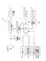
図2は、駐車補助装置2のシステム構成図である。
同図に示されるように、駐車補助装置2はそれを制御するコントローラ20を備え、該コントローラ20は、その中枢部となるCPU(中央演算装置)21、描画回路22、スーパーインポーズ回路23、同期分離回路24、音声合成回路25を備えている。CPU21は、入力手段、判断手段及び検出手段として機能しておりその内部で様々な演算を行っている。CPU21は、駐車目標位置入力スイッチ14により入力された駐車目標位置を基に駐車可否判断を行っている。
【0023】
グラフィックス描画回路22は、モニタ画面17にグラフィックスを描画している。スーパーインポーズ回路23は、グラフィックス信号とカメラ11からの後方画像を重ね合わせている。同期分離回路24は、カメラ画像から同期信号を抽出してグラフィックス描画回路22へ供給している。音声合成回路25は、スピーカ18から運転者に対して出力する音声案内を合成している。
【0024】
次に、実際に運転者が並列駐車を行うために駐車スイッチの並列駐車モードスイッチを作動させた時に行われるCPU21内部の演算について説明する。
運転者が並列駐車モードスイッチ15aを作動させると、モニタ画面17には図6に示すように並列駐車モードの目標駐車位置の入力画面30が表示される。入力画面30には駐車目標位置入力スイッチ14及び駐車目標位置を表す停止位置マーカ31が表示されている。駐車目標位置入力スイッチ14は、上下左右の各方向を向いた矢印14a〜14d及び両方向への回転を表す矢印14e,14fによって構成されている。停止位置マーカ31は、車両1の目標駐車位置を表しており、略四角形状をなしている。停止位置マーカ31は、入力画面30内で移動可能に設定されており、矢印14a〜14fによってその動きを制御されている。
【0025】
各矢印14a〜14fは、画面上に表示されるポインタで選択することによって停止位置マーカ31を任意の位置に動かしたり向きを変えたりするための指示信号をCPU21に送信している。
【0026】
停止位置マーカ31を任意の位置に動かした後、画面上に表示されている確定指示部32をポインタで選択すると、CPU21は目標駐車位置及び該目標駐車位置における車両の向きを一旦メモリに記憶する。
【0027】
目標駐車位置及び該目標駐車位置における車両の向きが入力されると、CPU21は現在の車両の状態と目標車両位置との幾何学的関係より駐車可否判断を行う。駐車可否判断は1回の旋回操作と直進の組み合わせによって目標駐車位置への駐車が可能かどうかによって行われる。並列駐車時の駐車可否判断は、以下に示す3つの幾何学的関係により判断され、3つの条件を全て満たしているとき目標駐車位置への駐車が可能であると判断される。また、駐車補助機能を停止したい場合には画面上に表示されている支援中止支持部33をポインタで選択することによって駐車補助機能が停止されるように制御されている。
【0028】
図7は、並列駐車時における駐車可否判断の第1の条件を表す説明図である。CPU21は、目標駐車位置の入力が行われると、同図に示すように駐車可否判断時における自車両1の姿勢に基づいて、自車両1の左右方向をX軸、自車両1の前後方向とZ軸に設定し、X軸とZ軸とからなる座標系(X,Z)を設定する。そして、CPU21は、自車両1の位置を座標の原点(0,0)に設定し、目標駐車位置の座標(X0,Z0)を原点(0,0)との相対的な位置関係によって計算するとともにメモリに記憶する。またCPU21は、現在位置における車両1の進行方向に対する目標駐車位置における車両の傾きを駐車角度θとしてメモリに記憶する。
【0029】
CPU21は、目標駐車位置の座標(X0,Z0)及び駐車角度θをメモリに記憶すると以下の計算を行う。
K=Z0・tan(θ)
自車両を1回の旋回操作と直進の組み合わせによって目標駐車位置へ駐車するためには、まず上記した式によって計算されるKの値がX0以上となる必要がある。すなわち、座標(X0,Z0)からZ軸に対して駐車角度θをなす方向に伸ばした直線とX軸との交点がX軸の負の領域となる必要がある。
【0030】
図8は、並列駐車時における駐車可否判断の第2の条件を表す説明図である。車両が目標車両位置に到達するためには、車両を目標車両位置に導くまでの予想経路を割り出したときに予想経路の旋回半径は、車両の旋回特性によって定まる車両の最小旋回半径(Rmin)よりも大きくないといけない。従って、CPU21は、予想経路の旋回操作終了点の座標(X1,Z1)を以下の演算式に従って求める。なお、ここでL1は、目標駐車位置に到達するために車両1の旋回後に行われる直進操作の距離を表している。
X1=X0−L1・sin(θ)
Z1=Z0−L1・cos(θ)
以上の演算によって座標(X1,Z1)を求めるとその結果をメモリに記憶し、次に以下の計算を行う。
D={(X1−Rmin)2+Z12}1/2
ここでDは、原点(0,0)から最小旋回運動を行ったときの旋回中心と、座標(X1,Z1)との距離を表している。そして、このDの値がRmin以上となる必要がある。
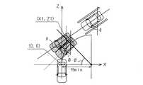
【0031】
図9は、並列駐車時における駐車可否判断の第3の条件を表す説明図である。車両が目標車両位置において目標とする角度で駐車されるためには、最小旋回半径Rminに対してRminより小さい半径で車両が旋回することはできない。従って、座標(X1,Z1)における駐車角度θについて最小旋回を行った場合の車両角度(経路上角度)φよりも大きく旋回することはできない。駐車可否判断を行うため、CPU21は、まず以下の式で経路上角度φを求めてメモリに記憶する。
φ=tan-1{Z1/(Rmin−X1)}
そして、上記の式で求められた経路上角度φが駐車角度θ以上の角度である必要がある。
【0032】
以上の3つの条件を全て満たす場合にはCPU21は、駐車目標位置に単純な操作にて駐車することが可能であると判断し、モニタ画面17に目標駐車位置に駐車可能である旨の表示をするとともにスピーカ18から所要の音声案内を出力する。
【0033】
一方、以上の3つの条件のうち1つでも条件を満たさない場合にはCPU21は、単純な操作にて駐車目標位置に駐車することが不可能であると判断し、モニタ画面17に目標駐車位置に駐車不可能である旨の表示をするとともにスピーカ18から所要の音声案内を出力する。
【0034】
次に、運転者が縦列駐車を行うために駐車スイッチを縦列駐車モードスイッチに入れた時に行われるCPU内部の演算について説明する。
運転者が縦列駐車モードスイッチ15bを作動させると、モニタ画面17には図示しない縦列駐車モードの目標駐車位置の入力画面が表示され、並列駐車時と同じように目標駐車位置の入力が行われる。
【0035】
目標駐車位置が入力されると、CPU21は現在の車両の位置と目標車両位置との幾何学的関係より駐車可否判断を行う。なお、縦列駐車時においては現在の車両の向きと駐車時の車両の向きが平行であることを前提に駐車可否判断が行われる。
【0036】
縦列駐車時の駐車可否判断は車両の一側への1回の旋回操作と、他側への1回の旋回操作と直進の組み合わせによって目標駐車位置への駐車が可能かどうかによって判断される。縦列駐車時の駐車可否判断は、以下に示す幾何学的関係により判断される。
【0037】
図10は、縦列駐車時における駐車可否判断の条件を表す説明図である。CPU21は、目標駐車位置の入力が行われると、図に示すように駐車可否判断時における自車両の位置を座標の原点(0,0)に設定し、目標駐車位置の座標(X0,Z0)を計算するとともにメモリに記憶する。車両は最小旋回半径Rminより小さい半径で車両が旋回することはできない。そこで、目標駐車位置に駐車を行うためには以下の条件式が成り立つ必要がある。
(2Rmin−X0)2+Z02≧(2Rmin)2
上記の条件を満たす場合にはCPU21は、単純な操作にて駐車目標位置に駐車することが可能であると判断し、モニタ画面17に目標駐車位置に駐車可能である旨の表示をするとともにスピーカ18から所要の音声案内を出力する。
【0038】
一方、上記の条件を満たさない場合にはCPU21は、単純な操作にて駐車目標位置に駐車することが不可能であると判断し、モニタ画面17に目標駐車位置に駐車不可能である旨の表示をするとともにスピーカ18から所要の音声案内を出力する。
【0039】
以上詳述したように、本実施形態によれば、以下に示す効果が得られるようになる。
(1)コントローラ20は、実際に車両1を操作する前に駐車可否判断をし、該判断結果を乗員に報知するようにした。従って、乗員は予め駐車の可否を知ることができ、車両の無駄な操縦を防止することができる。
【0040】
(2)駐車の可否判断の結果をモニタ画面17及び音声によって運転者に知らせる。従って、駐車の可否判断を運転者に認識させることができる。
(3)並列駐車時の駐車可否判断は1回の旋回操作と直進の組み合わせによって目標駐車位置への駐車が可能かどうかによって判断される。従って、駐車可能であると判断された時には運転者は簡単な操作によって目標駐車位置に確実に車両を駐車することができる。
【0041】
(4)縦列駐車時の駐車可否判断は一側への1回の旋回操作と他側への1回の旋回操作とによって目標駐車位置への駐車が可能かどうかによって判断される。従って、駐車可能であると判断された時には運転者は簡単な操作によって目標駐車位置に確実に車両を駐車することができる。
【0042】
なお、本発明の実施の形態は上記実施形態に限定されるものではなく、次のように変更してもよい。
・前記実施形態においては、駐車スイッチ15の並列駐車モードスイッチ15aを選択することで、駐車補助の処理動作を起動した。これに対して、例えば運転者から発せられる言葉に対する音声認識にて駐車補助の処理動作を起動するようにしてもよい。
【0043】
・前記実施形態における音声案内機能や画面切り替え機能は全ての運転者に一律に必要なものとは限らず、本装置に対する運転者の習熟度に応じて不要となる場合がある。従って、これら音声案内機能や画面切り替え機能を、運転者により個別に停止し得るような機能を設けてもよい。
【0044】
・前記実施形態においては、車両1の後方にカメラ11を設け、車両1を後退させて駐車する場合の駐車補助装置として説明した。これに対して、車両1の前方にカメラを設け、車両1を前進させて駐車する場合の駐車補助装置であってもよい。
【0045】
・前記実施形態においては、車両内で完結するシステムについて説明を行ったが、これに限定されるものではなく、車両外部から駐車に係わる外部信号を得て、外部信号に基づいて駐車補助を行うシステムにも適用が可能である。
【0046】
【発明の効果】
以上詳述したように、本発明によれば車両の操作前に予め車両の駐車可否判断が可能な駐車補助装置を提供することできる。
【図面の簡単な説明】
【図1】本発明の一実施形態を搭載した車両を示す概略図。
【図2】同実施形態のシステム構成図。
【図3】同実施形態のカメラの取付状態を示す側面図。
【図4】同実施形態のカメラの検出範囲を示す平面図。
【図5】同実施形態のカメラ及びモニタ画面の表示領域を示す説明図。
【図6】並列駐車モードの目標駐車位置の入力画面の説明図。
【図7】並列駐車時における駐車可否判断の第1の条件を表す説明図。
【図8】並列駐車時における駐車可否判断の第2の条件を表す説明図。
【図9】並列駐車時における駐車可否判断の第3の条件を表す説明図。
【図10】縦列駐車時における駐車可否判断の条件を表す説明図。
【符号の説明】
Rmin…最小旋回半径、1…車両、2…駐車補助装置、11…画像取得手段としてのカメラ、14…入力手段としての駐車目標位置入力スイッチ、17…報知手段としてのモニタ画面、18…報知手段としてのスピーカ、20…表示手段、入力手段、検出手段、判断手段及び報知手段としてのコントローラ。[0001]
BACKGROUND OF THE INVENTION
The present invention relates to a parking assistance device.
[0002]
[Prior art]
Conventionally, as a parking assistance device for assisting a driver in an operation during parking, an image obtained by photographing a landscape in a traveling direction of a vehicle with a camera is displayed on a monitor screen in a passenger compartment, for example, in Japanese Patent Laid-Open No. 11-334470. There is what is described. The parking assist device described in this publication assists the operation at the time of parking by superimposing and drawing a predicted traveling locus corresponding to the steering angle of the steering device on the monitor screen. That is, the driver operates the steering device or the like so that the driver can park at the required position with reference to the predicted travel locus together with the parking frame and the parked vehicle in the rear image, or performs the parking operation according to the instruction of the auxiliary device.
[0003]
The above-described parking assist device displays a predicted travel locus superimposed on the rear image on the monitor screen, and in particular by assisting a driver unfamiliar with the parking operation during the parking operation. It is effective in terms of facilitating garage entry in normal garage entry.
[0004]
[Problems to be solved by the invention]
However, even if the vehicle is operated according to such a parking assist device, correct parking at the parking target position cannot be performed. For example, the vehicle is not able to fit in the parking frame and the vehicle is tilted with respect to the parking frame. Was sometimes completed. Therefore, in such a case, there is a problem that the operation of the vehicle is wasted.
[0005]
The present invention has been made to solve the above-described problems, and an object of the present invention is to provide a parking assistance device that can determine whether or not a vehicle can be parked in advance before the operation of the vehicle.
[0006]
[Means for Solving the Problems]
According to the first aspect of the present invention, there is provided display means for displaying an image within the field of view from the own vehicle from the image acquisition means and displaying it on a monitor screen provided in the passenger compartment, and a target for parking the own vehicle on the monitor screen. Input means for inputting the parking position and the direction of the vehicle at the target parking position, and detecting a relative positional relationship between the target parking position set through the input means and the current vehicle position of the host vehicle, and Based on the detection means for detecting the inclination of the traveling direction of the host vehicle at the current vehicle position and the direction of the vehicle at the target parking position, and the host vehicle once the vehicle based on the relative positional relationship and the inclination. Determining means for determining whether the host vehicle can be parked from the current vehicle position to the target parking position by a combination of turning and straight traveling, and the determining means includes the host vehicle In the coordinate system in which the left and right directions are based on the current vehicle position, the X axis is a positive area in the left and right direction where the target parking position exists, and the Z axis is the front and rear direction. A straight line extending from the coordinates of the target parking position to the Z axis with respect to the Z axis, with the current vehicle position as the origin, setting the coordinates of the target parking position and setting the tilt as the parking angle; Toreach the target parking position when the intersection with the X-axis is the negative region of theX-axis, the point moved on theX-axis from the origin to the positive side by the minimum turning radius, and A distance from a turning operation end point, which is a position straight ahead from the target parking position by a distance of a straight running operation performed after turning of the vehicle, is larger than the minimum turning radius of the host vehicle, and on theX axis, Positive side from origin The target parking the vehicle from the current vehicle position whenthe minimum turning radius by anangle moved pointand said handedKaimisao operation end pointand the straight line and the X axis connecting the forms is an angle equal to or greater than the parkingangle Judged that parking is possible at the location.
[0010]
According to asecond aspect of the present invention, in thefirst aspect of the present invention, the information processing apparatus further includes a notification unit that notifies the determination result of the parking permission / prohibition by the determination unit.
[0011]
(Function)
According to the first aspect of the present invention, it is determined whether or not the host vehicle can be parked at a target parking position before the driver operates the host vehicle.
[0012]
Further, according to the invention described in
[0014]
According to the invention described in
[0015]
DETAILED DESCRIPTION OF THE INVENTION
Hereinafter, an embodiment embodying the present invention will be described with reference to FIGS.
As shown in FIG. 1, a
[0016]
The
[0017]
The
The parking target
[0018]
The
[0019]
The
The
[0020]
From the
The
[0021]
Further, the
[0022]
FIG. 2 is a system configuration diagram of the parking assist
As shown in the figure, the parking assist
[0023]
The graphics drawing circuit 22 draws graphics on the
[0024]
Next, the calculation inside the
When the driver operates the parallel
[0025]
Each of the
[0026]
After moving the
[0027]
When the target parking position and the direction of the vehicle at the target parking position are input, the
[0028]
FIG. 7 is an explanatory diagram illustrating a first condition for determining whether or not parking is possible during parallel parking. When the target parking position is input, the
[0029]
When the
K = Z0 · tan (θ)
In order to park the host vehicle at the target parking position by a combination of one turn operation and straight travel, first, the value of K calculated by the above formula needs to be X0 or more. That is, the intersection of the X axis and the straight line extended from the coordinates (X0, Z0) in the direction that forms the parking angle θ with respect to the Z axis needs to be the negative region of the X axis.
[0030]
FIG. 8 is an explanatory diagram illustrating a second condition for determining whether or not parking is possible during parallel parking. In order for the vehicle to reach the target vehicle position, when the predicted route until the vehicle is guided to the target vehicle position is determined, the turning radius of the predicted route is smaller than the minimum turning radius (Rmin) of the vehicle determined by the turning characteristics of the vehicle. Must also be large. Therefore, CPU21 calculates | requires the coordinate (X1, Z1) of the turning operation end point of an estimated path | route according to the following arithmetic expressions. Here, L1 represents the distance of the straight-ahead operation performed after the
X1 = X0−L1 · sin (θ)
Z1 = Z0−L1 · cos (θ)
When the coordinates (X1, Z1) are obtained by the above calculation, the result is stored in the memory, and then the following calculation is performed.
D = {(X1-Rmin)2 + Z12 }1/2
Here, D represents the distance between the turning center and the coordinates (X1, Z1) when the minimum turning motion is performed from the origin (0, 0). The value of D needs to be equal to or greater than Rmin.
[0031]
FIG. 9 is an explanatory diagram illustrating a third condition for determining whether or not parking is possible during parallel parking. In order for the vehicle to be parked at the target angle at the target vehicle position, the vehicle cannot turn at a radius smaller than Rmin with respect to the minimum turning radius Rmin. Therefore, the vehicle cannot turn larger than the vehicle angle (angle on the route) φ when the minimum turn is performed with respect to the parking angle θ at the coordinates (X1, Z1). In order to determine whether or not parking is possible, the
φ = tan−1 {Z1 / (Rmin−X1)}
Then, the on-route angle φ obtained by the above formula needs to be an angle equal to or larger than the parking angle θ.
[0032]
When all of the above three conditions are satisfied, the
[0033]
On the other hand, if any one of the above three conditions is not satisfied, the
[0034]
Next, the calculation inside the CPU that is performed when the driver puts the parking switch into the parallel parking mode switch to perform parallel parking will be described.
When the driver operates the parallel
[0035]
When the target parking position is input, the
[0036]
Whether or not parking is possible in parallel parking is determined by whether or not parking at the target parking position is possible by a combination of one turning operation to one side of the vehicle and one turning operation to the other side and straight travel. The determination as to whether parking is allowed in parallel parking is made based on the geometric relationship shown below.
[0037]
FIG. 10 is an explanatory diagram showing conditions for determining whether or not parking is possible during parallel parking. When the target parking position is input, the
(2Rmin−X0)2 + Z02 ≧ (2Rmin)2
If the above conditions are satisfied, the
[0038]
On the other hand, if the above condition is not satisfied, the
[0039]
As described above in detail, according to the present embodiment, the following effects can be obtained.
(1) The
[0040]
(2) The driver is informed of the result of the determination of whether or not parking is possible by using the
(3) Whether to park at the time of parallel parking is determined by whether or not parking at the target parking position is possible by a combination of one turn operation and straight travel. Therefore, when it is determined that parking is possible, the driver can securely park the vehicle at the target parking position by a simple operation.
[0041]
(4) Whether to park in parallel parking is determined by whether or not parking at the target parking position is possible by one turning operation to one side and one turning operation to the other side. Therefore, when it is determined that parking is possible, the driver can securely park the vehicle at the target parking position by a simple operation.
[0042]
In addition, embodiment of this invention is not limited to the said embodiment, You may change as follows.
In the embodiment, the parking assist processing operation is activated by selecting the parallel
[0043]
The voice guidance function and the screen switching function in the above embodiment are not necessarily required uniformly for all drivers, and may be unnecessary depending on the driver's proficiency with respect to the present apparatus. Therefore, the voice guidance function and the screen switching function may be provided with a function that can be individually stopped by the driver.
[0044]
In the above-described embodiment, the
[0045]
In the above embodiment, the system completed in the vehicle has been described. However, the present invention is not limited to this, and an external signal related to parking is obtained from outside the vehicle, and parking assistance is performed based on the external signal. It can also be applied to the system.
[0046]
【The invention's effect】
As described above in detail, according to the present invention, it is possible to provide a parking assist device that can determine whether or not a vehicle can be parked in advance before the operation of the vehicle.
[Brief description of the drawings]
FIG. 1 is a schematic view showing a vehicle equipped with an embodiment of the present invention.
FIG. 2 is a system configuration diagram of the embodiment.
FIG. 3 is a side view showing a mounting state of the camera of the embodiment.
FIG. 4 is a plan view showing a detection range of the camera of the embodiment.
FIG. 5 is an explanatory diagram showing a display area of a camera and a monitor screen according to the embodiment.
FIG. 6 is an explanatory diagram of an input screen for a target parking position in the parallel parking mode.
FIG. 7 is an explanatory diagram illustrating a first condition for determining whether or not parking is possible during parallel parking.
FIG. 8 is an explanatory diagram showing a second condition for determining whether or not parking is possible at the time of parallel parking.
FIG. 9 is an explanatory diagram showing a third condition for determining whether or not parking is possible during parallel parking.
FIG. 10 is an explanatory diagram showing conditions for determining whether or not parking is possible during parallel parking.
[Explanation of symbols]
Rmin: minimum turning radius, 1 ... vehicle, 2 ... parking assist device, 11 ... camera as image acquisition means, 14 ... parking target position input switch as input means, 17 ... monitor screen as notification means, 18 ... notification means As a speaker, 20... Display means, input means, detection means, determination means and controller as notification means.
Claims (2)
Translated fromJapanese前記モニタ画面上において前記自車両を駐車する目標駐車位置及び該目標駐車位置における車両の向きを入力する入力手段と、
前記入力手段を通じて設定された目標駐車位置と前記自車両の現在の車両位置との相対的な位置関係を検出するとともに、前記自車両の現在の車両位置における進行方向と前記目標駐車位置における車両の向きとの傾きを検出する検出手段と、
前記相対的な位置関係と前記傾きとに基づいて前記自車両が車両の1回の旋回と直進との組み合わせによって前記自車両を現在の車両位置から前記目標駐車位置に駐車可能かどうかを判断する判断手段とを備え、
前記判断手段は、
前記自車両の現在の車両位置における向きに基づいて左右方向を、その左右方向のうち前記目標駐車位置が存在する側を正の領域とするX軸、前後方向をZ軸とする座標系において、前記自車両の現在の車両位置を原点とし、前記目標駐車位置の座標を設定するとともに前記傾きを駐車角度として設定し、前記目標駐車位置の座標からZ軸に対して前記駐車角度をなす方向に伸ばした直線とX軸との交点がX軸の負の領域となる場合であり、かつ、
X軸上であって原点から正の側に最小旋回半径だけ移動した点と、前記目標駐車位置に到達するために車両の旋回後に行われる直進操作の距離だけ前記目標駐車位置から直進した位置である旋回操作終了点との距離が前記自車両の最小旋回半径より大きい場合であり、かつ、
X軸上であって原点から正の側に最小旋回半径だけ移動した点と前記旋回操作終了点とを結ぶ直線とX軸とがなす角度が前記駐車角度以上の角度である場合
に前記自車両を現在の車両位置から前記目標駐車位置に駐車可能であると判断することを特徴とする駐車補助装置。Display means for obtaining an in-view image from the own vehicle from the image acquisition means and displaying it on a monitor screen provided in the vehicle interior;
Input means for inputting a target parking position for parking the host vehicle on the monitor screen and a direction of the vehicle at the target parking position;
The relative position relationship between the target parking position set through the input means and the current vehicle position of the host vehicle is detected, and the traveling direction of the host vehicle at the current vehicle position and the vehicle position at the target parking position are detected. Detection means for detecting the inclination of the direction;
Based on the relative positional relationship and the inclination, the host vehicle determines whether the host vehicle can be parked from the current vehicle position to the target parking position by a combination of one turn of the vehicle and straight travel. Judgment means,
The determination means includes
In a coordinate system in which the left-right direction is based on the direction of the current vehicle position of the host vehicle, the X-axis is a positive region of the left-right direction where the target parking position exists, and the front-rear direction is a Z-axis. The current vehicle position of the host vehicle is set as the origin, the coordinates of the target parking position are set, the inclination is set as a parking angle, and the parking angle is set from the coordinates of the target parking position with respect to the Z axis. The intersection of the stretched straight line and the X axis is the negative region of the X axis, and
A point on the X axis that has moved by a minimum turning radius from the origin to the positive side, and a position that has moved straight from the target parking position by a distance of a straight-ahead operation that is performed after the vehicle turns to reach the target parking position. The distance to acertain turning operation end point is greater than the minimum turning radius of the host vehicle, and
Wherein when the angleformed by the straight line and the X axis connectingfrom the origin A on the X axis and the point that has moved to the positive side by the minimum turning radiusand the handedKaimisao work end point is an angle of more than the parking angle A parking assist device that judges that the host vehicle can be parked from the current vehicle position to the target parking position.
Priority Applications (4)
| Application Number | Priority Date | Filing Date | Title |
|---|---|---|---|
| JP2002105769AJP4342146B2 (en) | 2002-04-08 | 2002-04-08 | Parking assistance device |
| DE60314676TDE60314676T2 (en) | 2002-04-08 | 2003-04-07 | Device for parking aid |
| EP03007895AEP1352782B1 (en) | 2002-04-08 | 2003-04-07 | Parking assist system |
| US10/408,232US6950035B2 (en) | 2002-04-08 | 2003-04-08 | Parking assist system with image obtaining means and displaying means |
Applications Claiming Priority (1)
| Application Number | Priority Date | Filing Date | Title |
|---|---|---|---|
| JP2002105769AJP4342146B2 (en) | 2002-04-08 | 2002-04-08 | Parking assistance device |
Publications (2)
| Publication Number | Publication Date |
|---|---|
| JP2003300443A JP2003300443A (en) | 2003-10-21 |
| JP4342146B2true JP4342146B2 (en) | 2009-10-14 |
Family
ID=28449911
Family Applications (1)
| Application Number | Title | Priority Date | Filing Date |
|---|---|---|---|
| JP2002105769AExpired - Fee RelatedJP4342146B2 (en) | 2002-04-08 | 2002-04-08 | Parking assistance device |
Country Status (4)
| Country | Link |
|---|---|
| US (1) | US6950035B2 (en) |
| EP (1) | EP1352782B1 (en) |
| JP (1) | JP4342146B2 (en) |
| DE (1) | DE60314676T2 (en) |
Families Citing this family (111)
| Publication number | Priority date | Publication date | Assignee | Title |
|---|---|---|---|---|
| US5877897A (en) | 1993-02-26 | 1999-03-02 | Donnelly Corporation | Automatic rearview mirror, vehicle lighting control and vehicle interior monitoring system using a photosensor array |
| US5910854A (en) | 1993-02-26 | 1999-06-08 | Donnelly Corporation | Electrochromic polymeric solid films, manufacturing electrochromic devices using such solid films, and processes for making such solid films and devices |
| US6822563B2 (en) | 1997-09-22 | 2004-11-23 | Donnelly Corporation | Vehicle imaging system with accessory control |
| US5668663A (en) | 1994-05-05 | 1997-09-16 | Donnelly Corporation | Electrochromic mirrors and devices |
| US6891563B2 (en) | 1996-05-22 | 2005-05-10 | Donnelly Corporation | Vehicular vision system |
| US7655894B2 (en) | 1996-03-25 | 2010-02-02 | Donnelly Corporation | Vehicular image sensing system |
| US6172613B1 (en) | 1998-02-18 | 2001-01-09 | Donnelly Corporation | Rearview mirror assembly incorporating vehicle information display |
| US6326613B1 (en) | 1998-01-07 | 2001-12-04 | Donnelly Corporation | Vehicle interior mirror assembly adapted for containing a rain sensor |
| US6124886A (en) | 1997-08-25 | 2000-09-26 | Donnelly Corporation | Modular rearview mirror assembly |
| US8294975B2 (en) | 1997-08-25 | 2012-10-23 | Donnelly Corporation | Automotive rearview mirror assembly |
| US8288711B2 (en) | 1998-01-07 | 2012-10-16 | Donnelly Corporation | Interior rearview mirror system with forwardly-viewing camera and a control |
| US6445287B1 (en) | 2000-02-28 | 2002-09-03 | Donnelly Corporation | Tire inflation assistance monitoring system |
| US6693517B2 (en) | 2000-04-21 | 2004-02-17 | Donnelly Corporation | Vehicle mirror assembly communicating wirelessly with vehicle accessories and occupants |
| US6329925B1 (en) | 1999-11-24 | 2001-12-11 | Donnelly Corporation | Rearview mirror assembly with added feature modular display |
| US6477464B2 (en) | 2000-03-09 | 2002-11-05 | Donnelly Corporation | Complete mirror-based global-positioning system (GPS) navigation solution |
| US7167796B2 (en) | 2000-03-09 | 2007-01-23 | Donnelly Corporation | Vehicle navigation system for use with a telematics system |
| US7370983B2 (en) | 2000-03-02 | 2008-05-13 | Donnelly Corporation | Interior mirror assembly with display |
| AU2001243285A1 (en) | 2000-03-02 | 2001-09-12 | Donnelly Corporation | Video mirror systems incorporating an accessory module |
| AU2002251807A1 (en) | 2001-01-23 | 2002-08-19 | Donnelly Corporation | Improved vehicular lighting system for a mirror assembly |
| US7581859B2 (en) | 2005-09-14 | 2009-09-01 | Donnelly Corp. | Display device for exterior rearview mirror |
| US7255451B2 (en) | 2002-09-20 | 2007-08-14 | Donnelly Corporation | Electro-optic mirror cell |
| ES2391556T3 (en) | 2002-05-03 | 2012-11-27 | Donnelly Corporation | Object detection system for vehicles |
| US6918674B2 (en) | 2002-05-03 | 2005-07-19 | Donnelly Corporation | Vehicle rearview mirror system |
| US7329013B2 (en) | 2002-06-06 | 2008-02-12 | Donnelly Corporation | Interior rearview mirror system with compass |
| AU2003237424A1 (en) | 2002-06-06 | 2003-12-22 | Donnelly Corporation | Interior rearview mirror system with compass |
| WO2004103772A2 (en) | 2003-05-19 | 2004-12-02 | Donnelly Corporation | Mirror assembly for vehicle |
| US7310177B2 (en) | 2002-09-20 | 2007-12-18 | Donnelly Corporation | Electro-optic reflective element assembly |
| WO2004026633A2 (en) | 2002-09-20 | 2004-04-01 | Donnelly Corporation | Mirror reflective element assembly |
| DE10257722A1 (en)* | 2002-12-11 | 2004-07-01 | Robert Bosch Gmbh | parking aid |
| JP4427953B2 (en)* | 2003-01-29 | 2010-03-10 | 株式会社豊田自動織機 | Parking assistance device |
| JP4235026B2 (en)* | 2003-04-28 | 2009-03-04 | トヨタ自動車株式会社 | Parking assistance device |
| JP3866223B2 (en)* | 2003-05-29 | 2007-01-10 | トヨタ自動車株式会社 | Vehicle travel support device |
| JP4316960B2 (en) | 2003-08-22 | 2009-08-19 | 株式会社半導体エネルギー研究所 | apparatus |
| US7446924B2 (en) | 2003-10-02 | 2008-11-04 | Donnelly Corporation | Mirror reflective element assembly including electronic component |
| US7308341B2 (en) | 2003-10-14 | 2007-12-11 | Donnelly Corporation | Vehicle communication system |
| DE10351894A1 (en)* | 2003-11-06 | 2005-06-09 | Robert Bosch Gmbh | Method for determining a parking space |
| US7526103B2 (en) | 2004-04-15 | 2009-04-28 | Donnelly Corporation | Imaging system for vehicle |
| JP2005313710A (en) | 2004-04-27 | 2005-11-10 | Toyota Motor Corp | Parking assistance device |
| DE102004027250A1 (en)* | 2004-06-03 | 2005-12-29 | Magna Donnelly Gmbh & Co. Kg | Method and device for assisted control of a motor vehicle |
| US7881496B2 (en) | 2004-09-30 | 2011-02-01 | Donnelly Corporation | Vision system for vehicle |
| JP4604703B2 (en)* | 2004-12-21 | 2011-01-05 | アイシン精機株式会社 | Parking assistance device |
| EP1827951A2 (en)* | 2004-12-24 | 2007-09-05 | Continental Teves AG & Co. oHG | Method for guiding a vehicle into a parking space, and parking assistance device |
| EP1883855B1 (en) | 2005-05-16 | 2011-07-20 | Donnelly Corporation | Vehicle mirror assembly with indicia at reflective element |
| EP1955904B1 (en)* | 2005-10-31 | 2013-03-27 | Toyota Jidosha Kabushiki Kaisha | Parking support device |
| EP1949666B1 (en) | 2005-11-01 | 2013-07-17 | Magna Mirrors of America, Inc. | Interior rearview mirror with display |
| JP4414959B2 (en)* | 2005-11-16 | 2010-02-17 | アイシン精機株式会社 | Parking assistance device |
| US8194132B2 (en) | 2006-01-20 | 2012-06-05 | Old World Industries, Llc | System for monitoring an area adjacent a vehicle |
| CN101401024B (en) | 2006-03-09 | 2016-03-16 | 金泰克斯公司 | Comprise the vehicle rearview assembly of high intensity display |
| WO2008024639A2 (en) | 2006-08-11 | 2008-02-28 | Donnelly Corporation | Automatic headlamp control system |
| JP5003946B2 (en)* | 2007-05-30 | 2012-08-22 | アイシン精機株式会社 | Parking assistance device |
| JP4919064B2 (en)* | 2007-07-23 | 2012-04-18 | 株式会社デンソー | Vehicle display device |
| US8154418B2 (en) | 2008-03-31 | 2012-04-10 | Magna Mirrors Of America, Inc. | Interior rearview mirror system |
| JP2009292339A (en)* | 2008-06-05 | 2009-12-17 | Aisin Seiki Co Ltd | Parking assistant device |
| US9487144B2 (en) | 2008-10-16 | 2016-11-08 | Magna Mirrors Of America, Inc. | Interior mirror assembly with display |
| US20100152972A1 (en)* | 2008-12-15 | 2010-06-17 | Joe Charles Attard | Parallel park assist |
| JP4790037B2 (en)* | 2009-03-23 | 2011-10-12 | トヨタ自動車株式会社 | Parking assistance device |
| DE102009029436A1 (en) | 2009-09-14 | 2011-03-24 | Robert Bosch Gmbh | Procedure for parking a vehicle |
| EP2672354B1 (en)* | 2011-01-31 | 2020-03-04 | Toyota Jidosha Kabushiki Kaisha | Vehicle control apparatus |
| DE102011003881A1 (en)* | 2011-02-09 | 2012-08-09 | Robert Bosch Gmbh | Method for assisting a driver of a motor vehicle |
| US9426364B2 (en)* | 2011-09-05 | 2016-08-23 | Mitsubishi Electric Corporation | Image processing apparatus and image processing method |
| US20140118533A1 (en)* | 2012-01-27 | 2014-05-01 | Doosan Infracore Co., Ltd. | Operational stability enhancing device for construction machinery |
| US10457209B2 (en) | 2012-02-22 | 2019-10-29 | Magna Electronics Inc. | Vehicle vision system with multi-paned view |
| US9319637B2 (en) | 2012-03-27 | 2016-04-19 | Magna Electronics Inc. | Vehicle vision system with lens pollution detection |
| US8879139B2 (en) | 2012-04-24 | 2014-11-04 | Gentex Corporation | Display mirror assembly |
| US9707896B2 (en) | 2012-10-15 | 2017-07-18 | Magna Electronics Inc. | Vehicle camera lens dirt protection via air flow |
| US9445057B2 (en) | 2013-02-20 | 2016-09-13 | Magna Electronics Inc. | Vehicle vision system with dirt detection |
| KR101881346B1 (en) | 2013-03-15 | 2018-07-24 | 젠텍스 코포레이션 | Display mirror assembly |
| US9674490B2 (en) | 2013-04-18 | 2017-06-06 | Magna Electronics Inc. | Vision system for vehicle with adjustable cameras |
| KR101448786B1 (en)* | 2013-05-22 | 2014-10-13 | 현대자동차 주식회사 | Smart parking assistant system and parking balance method |
| JP2016534915A (en) | 2013-09-24 | 2016-11-10 | ジェンテックス コーポレイション | Display mirror assembly |
| CN103625365B (en)* | 2013-10-25 | 2016-08-24 | 江西好帮手电子科技有限公司 | A kind of parking auxiliary monitoring system and its implementation |
| KR101498973B1 (en)* | 2013-11-21 | 2015-03-05 | 현대모비스(주) | Parking asistance system and parking asistance method |
| US9207677B2 (en)* | 2014-01-02 | 2015-12-08 | Automotive Research & Testing Center | Vehicle positioning method and its system |
| US9511715B2 (en) | 2014-01-31 | 2016-12-06 | Gentex Corporation | Backlighting assembly for display for reducing cross-hatching |
| US10705332B2 (en) | 2014-03-21 | 2020-07-07 | Gentex Corporation | Tri-modal display mirror assembly |
| KR101894262B1 (en) | 2014-04-01 | 2018-09-04 | 젠텍스 코포레이션 | Automatic display mirror assembly |
| US9694751B2 (en) | 2014-09-19 | 2017-07-04 | Gentex Corporation | Rearview assembly |
| WO2016073848A1 (en) | 2014-11-07 | 2016-05-12 | Gentex Corporation | Full display mirror actuator |
| US10071689B2 (en) | 2014-11-13 | 2018-09-11 | Gentex Corporation | Rearview mirror system with a display |
| US10131279B2 (en) | 2014-12-03 | 2018-11-20 | Gentex Corporation | Display mirror assembly with an RF shield bezel |
| USD746744S1 (en) | 2014-12-05 | 2016-01-05 | Gentex Corporation | Rearview device |
| US9744907B2 (en) | 2014-12-29 | 2017-08-29 | Gentex Corporation | Vehicle vision system having adjustable displayed field of view |
| US9720278B2 (en) | 2015-01-22 | 2017-08-01 | Gentex Corporation | Low cost optical film stack |
| JP2018513810A (en) | 2015-04-20 | 2018-05-31 | ジェンテックス コーポレイション | Rear view assembly with decoration |
| EP3297870B1 (en) | 2015-05-18 | 2020-02-05 | Gentex Corporation | Full display rearview device |
| WO2016209877A1 (en) | 2015-06-22 | 2016-12-29 | Gentex Corporation | System and method for processing streamed video images to correct for flicker of amplitude-modulated lights |
| JP6642820B2 (en) | 2015-10-21 | 2020-02-12 | 日立オートモティブシステムズ株式会社 | Parking route calculation device, parking support device, and parking route calculation method |
| USD798207S1 (en) | 2015-10-30 | 2017-09-26 | Gentex Corporation | Rearview mirror assembly |
| CN108349436B (en) | 2015-10-30 | 2019-12-20 | 金泰克斯公司 | Rear-view device |
| WO2017075420A1 (en) | 2015-10-30 | 2017-05-04 | Gentex Corporation | Toggle paddle |
| USD797627S1 (en) | 2015-10-30 | 2017-09-19 | Gentex Corporation | Rearview mirror device |
| USD800618S1 (en) | 2015-11-02 | 2017-10-24 | Gentex Corporation | Toggle paddle for a rear view device |
| US9787951B2 (en)* | 2015-12-18 | 2017-10-10 | Serge Kannon | Vehicle proximity warning system |
| USD845851S1 (en) | 2016-03-31 | 2019-04-16 | Gentex Corporation | Rearview device |
| USD817238S1 (en) | 2016-04-29 | 2018-05-08 | Gentex Corporation | Rearview device |
| US10025138B2 (en) | 2016-06-06 | 2018-07-17 | Gentex Corporation | Illuminating display with light gathering structure |
| JP6868805B2 (en)* | 2016-06-07 | 2021-05-12 | パナソニックIpマネジメント株式会社 | Image generator, image generator, and program |
| JP6644425B2 (en)* | 2016-07-07 | 2020-02-12 | アルパイン株式会社 | Travel route generation device and travel route generation method |
| EP3269678B1 (en) | 2016-07-14 | 2019-03-06 | Toyota Material Handling Manufacturing Sweden AB | Floor conveyor |
| EP3269680B1 (en) | 2016-07-14 | 2020-09-30 | Toyota Material Handling Manufacturing Sweden AB | Floor conveyor |
| EP3269679B2 (en) | 2016-07-14 | 2024-12-04 | Toyota Material Handling Manufacturing Sweden AB | Floor conveyor |
| USD809984S1 (en) | 2016-12-07 | 2018-02-13 | Gentex Corporation | Rearview assembly |
| USD854473S1 (en) | 2016-12-16 | 2019-07-23 | Gentex Corporation | Rearview assembly |
| KR20190104990A (en) | 2016-12-30 | 2019-09-11 | 젠텍스 코포레이션 | Full display mirror with instant custom spotter view |
| DE102017202259A1 (en)* | 2017-02-13 | 2018-08-16 | Ford Global Technologies, Llc | Method and device for supporting a parking process of a motor vehicle |
| EP3595931A4 (en) | 2017-03-17 | 2020-01-22 | Gentex Corporation | REVIEW REVERSE CAMERA WITH TWO |
| DE102017106844A1 (en) | 2017-03-30 | 2018-10-04 | Valeo Schalter Und Sensoren Gmbh | Evaluation of the complexity of a parking operation |
| US10614721B2 (en) | 2017-06-08 | 2020-04-07 | International Business Machines Corporation | Providing parking assistance based on multiple external parking data sources |
| CN118714310A (en)* | 2019-09-19 | 2024-09-27 | 数码士有限公司 | Video signal processing method and device using scaling processing |
| US11994272B2 (en) | 2021-08-20 | 2024-05-28 | Gentex Corporation | Lighting assembly and illumination system having a lighting assembly |
| GB2617427A (en)* | 2021-12-06 | 2023-10-11 | Mbda Uk Ltd | Apparatus and method for imaging |
Family Cites Families (25)
| Publication number | Priority date | Publication date | Assignee | Title |
|---|---|---|---|---|
| US4931930A (en)* | 1988-04-19 | 1990-06-05 | Industrial Technology Research Institute | Automatic parking device for automobile |
| JP3396893B2 (en)* | 1992-05-25 | 2003-04-14 | 株式会社デンソー | Garage guidance system for vehicles |
| JPH082357A (en)* | 1994-06-20 | 1996-01-09 | Nissan Motor Co Ltd | Vehicle parking assist device |
| JP3362569B2 (en)* | 1995-08-04 | 2003-01-07 | 三菱自動車工業株式会社 | Vehicle guidance device |
| JP3362584B2 (en)* | 1995-12-22 | 2003-01-07 | 三菱自動車工業株式会社 | Parking judgment device |
| JPH10264840A (en)* | 1997-03-25 | 1998-10-06 | Nissan Motor Co Ltd | Parking guidance device |
| JPH10264841A (en)* | 1997-03-25 | 1998-10-06 | Nissan Motor Co Ltd | Parking guidance device |
| JP3044534B2 (en)* | 1997-04-28 | 2000-05-22 | 本田技研工業株式会社 | Automatic vehicle steering system |
| JPH11157404A (en)* | 1997-11-26 | 1999-06-15 | Toyota Motor Corp | Parking assistance device |
| JP3575279B2 (en) | 1998-05-22 | 2004-10-13 | アイシン精機株式会社 | Parking assistance device |
| JP3951465B2 (en)* | 1998-06-26 | 2007-08-01 | アイシン精機株式会社 | Parking assistance device |
| FR2785383B1 (en)* | 1998-10-30 | 2000-12-15 | Renault | METHOD AND DEVICE FOR ASSISTING THE MOVEMENT OF A VEHICLE WITH A VIEW IN PARTICULAR TO PARKING IT |
| JP4096445B2 (en)* | 1999-03-31 | 2008-06-04 | アイシン精機株式会社 | Parking assistance device |
| JP2000335342A (en)* | 1999-05-26 | 2000-12-05 | Yazaki Corp | Parking assistance device |
| JP4426014B2 (en)* | 1999-06-29 | 2010-03-03 | 富士通テン株式会社 | Vehicle parking assist device |
| JP4104796B2 (en)* | 1999-10-04 | 2008-06-18 | 矢崎総業株式会社 | Parking assistance device |
| JP3427823B2 (en)* | 2000-02-29 | 2003-07-22 | 株式会社豊田自動織機 | Backing support device for parallel parking |
| JP3374833B2 (en)* | 2000-05-12 | 2003-02-10 | 株式会社豊田自動織機 | Vehicle reversal support device when parking |
| EP1944222A3 (en)* | 2000-05-12 | 2011-11-09 | Kabushiki Kaisha Toyota Jidoshokki | Vehicle backward movement assisting apparatus |
| JP3693912B2 (en)* | 2000-05-30 | 2005-09-14 | アイシン精機株式会社 | Relative position detection device and parking assist device provided with the relative position detection device |
| JP3466549B2 (en)* | 2000-07-03 | 2003-11-10 | トヨタ自動車株式会社 | Parallel parking assist device |
| JP3619753B2 (en)* | 2000-07-03 | 2005-02-16 | トヨタ自動車株式会社 | Rear view display device for moving object |
| JP2002036991A (en)* | 2000-07-27 | 2002-02-06 | Honda Motor Co Ltd | Parking assistance device |
| JP3700614B2 (en)* | 2001-06-22 | 2005-09-28 | 株式会社豊田自動織機 | Parking assistance device |
| US6683539B2 (en)* | 2001-12-27 | 2004-01-27 | Koninklijke Philips Electronics N.V. | Computer vision based parking assistant |
- 2002
- 2002-04-08JPJP2002105769Apatent/JP4342146B2/ennot_activeExpired - Fee Related
- 2003
- 2003-04-07EPEP03007895Apatent/EP1352782B1/ennot_activeExpired - Lifetime
- 2003-04-07DEDE60314676Tpatent/DE60314676T2/ennot_activeExpired - Lifetime
- 2003-04-08USUS10/408,232patent/US6950035B2/ennot_activeExpired - Lifetime
Also Published As
| Publication number | Publication date |
|---|---|
| US20030222793A1 (en) | 2003-12-04 |
| DE60314676D1 (en) | 2007-08-16 |
| EP1352782B1 (en) | 2007-07-04 |
| EP1352782A2 (en) | 2003-10-15 |
| US6950035B2 (en) | 2005-09-27 |
| JP2003300443A (en) | 2003-10-21 |
| EP1352782A3 (en) | 2004-12-29 |
| DE60314676T2 (en) | 2008-04-10 |
Similar Documents
| Publication | Publication Date | Title |
|---|---|---|
| JP4342146B2 (en) | Parking assistance device | |
| EP3650285B1 (en) | Parking assistance method and parking assistance device | |
| JP4855158B2 (en) | Driving assistance device | |
| JP5212748B2 (en) | Parking assistance device | |
| US6487481B2 (en) | Parking assisting apparatus | |
| JP5337878B2 (en) | Driving assistance device | |
| KR100552337B1 (en) | Parking support device | |
| JP2006264389A (en) | Parking support device | |
| JP2009154654A (en) | Vehicle parking assist device and video display method | |
| JP2008013015A (en) | Vehicle surroundings image producing device and image switching method | |
| JP2008302711A (en) | Start support device | |
| JP5549235B2 (en) | Driving assistance device | |
| JP5380994B2 (en) | Parking assistance device and parking assistance method | |
| JP2012056428A (en) | Driving support device | |
| JP4797849B2 (en) | Driving support image display system and in-vehicle device | |
| JP5556077B2 (en) | Driving support device | |
| JP2008279875A (en) | Parking support device | |
| JP2012076551A (en) | Parking support device, parking support method, and parking support system | |
| US20200140011A1 (en) | Parking assistance apparatus | |
| JP2010154304A (en) | Mobile camera system and driving method | |
| JP2008213647A (en) | Parking assist method and parking assist system | |
| JP5273068B2 (en) | Vehicle periphery monitoring device | |
| JP3762855B2 (en) | Parking assistance device | |
| JP2011003117A (en) | Backward visual recognition support system | |
| JP3762854B2 (en) | Parking assistance device |
Legal Events
| Date | Code | Title | Description |
|---|---|---|---|
| A621 | Written request for application examination | Free format text:JAPANESE INTERMEDIATE CODE: A621 Effective date:20050404 | |
| A977 | Report on retrieval | Free format text:JAPANESE INTERMEDIATE CODE: A971007 Effective date:20060615 | |
| A131 | Notification of reasons for refusal | Free format text:JAPANESE INTERMEDIATE CODE: A131 Effective date:20060627 | |
| A521 | Request for written amendment filed | Free format text:JAPANESE INTERMEDIATE CODE: A523 Effective date:20060828 | |
| A131 | Notification of reasons for refusal | Free format text:JAPANESE INTERMEDIATE CODE: A131 Effective date:20070227 | |
| A521 | Request for written amendment filed | Free format text:JAPANESE INTERMEDIATE CODE: A523 Effective date:20070427 | |
| A131 | Notification of reasons for refusal | Free format text:JAPANESE INTERMEDIATE CODE: A131 Effective date:20071211 | |
| A521 | Request for written amendment filed | Free format text:JAPANESE INTERMEDIATE CODE: A523 Effective date:20080212 | |
| A131 | Notification of reasons for refusal | Free format text:JAPANESE INTERMEDIATE CODE: A131 Effective date:20081111 | |
| A521 | Request for written amendment filed | Free format text:JAPANESE INTERMEDIATE CODE: A523 Effective date:20090113 | |
| A131 | Notification of reasons for refusal | Free format text:JAPANESE INTERMEDIATE CODE: A131 Effective date:20090203 | |
| A521 | Request for written amendment filed | Free format text:JAPANESE INTERMEDIATE CODE: A523 Effective date:20090406 | |
| TRDD | Decision of grant or rejection written | ||
| A01 | Written decision to grant a patent or to grant a registration (utility model) | Free format text:JAPANESE INTERMEDIATE CODE: A01 Effective date:20090630 | |
| A01 | Written decision to grant a patent or to grant a registration (utility model) | Free format text:JAPANESE INTERMEDIATE CODE: A01 | |
| A61 | First payment of annual fees (during grant procedure) | Free format text:JAPANESE INTERMEDIATE CODE: A61 Effective date:20090707 | |
| FPAY | Renewal fee payment (event date is renewal date of database) | Free format text:PAYMENT UNTIL: 20120717 Year of fee payment:3 | |
| R151 | Written notification of patent or utility model registration | Ref document number:4342146 Country of ref document:JP Free format text:JAPANESE INTERMEDIATE CODE: R151 | |
| FPAY | Renewal fee payment (event date is renewal date of database) | Free format text:PAYMENT UNTIL: 20120717 Year of fee payment:3 | |
| FPAY | Renewal fee payment (event date is renewal date of database) | Free format text:PAYMENT UNTIL: 20120717 Year of fee payment:3 | |
| FPAY | Renewal fee payment (event date is renewal date of database) | Free format text:PAYMENT UNTIL: 20130717 Year of fee payment:4 | |
| LAPS | Cancellation because of no payment of annual fees |