JP4340827B2 - ANTENNA MOUNTING DEVICE, ITS MOUNTING METHOD, AND SATELLITE RADIO RECEIVE ANTENNA DEVICE - Google Patents
ANTENNA MOUNTING DEVICE, ITS MOUNTING METHOD, AND SATELLITE RADIO RECEIVE ANTENNA DEVICEDownload PDFInfo
- Publication number
- JP4340827B2 JP4340827B2JP2000141630AJP2000141630AJP4340827B2JP 4340827 B2JP4340827 B2JP 4340827B2JP 2000141630 AJP2000141630 AJP 2000141630AJP 2000141630 AJP2000141630 AJP 2000141630AJP 4340827 B2JP4340827 B2JP 4340827B2
- Authority
- JP
- Japan
- Prior art keywords
- antenna
- fixing
- fixing members
- bolts
- attached
- Prior art date
- Legal status (The legal status is an assumption and is not a legal conclusion. Google has not performed a legal analysis and makes no representation as to the accuracy of the status listed.)
- Expired - Fee Related
Links
- 238000009434installationMethods0.000description8
- 238000010586diagramMethods0.000description5
- 230000008602contractionEffects0.000description3
- 229910052782aluminiumInorganic materials0.000description2
- XAGFODPZIPBFFR-UHFFFAOYSA-NaluminiumChemical compound[Al]XAGFODPZIPBFFR-UHFFFAOYSA-N0.000description2
- 229910052751metalInorganic materials0.000description2
- 239000002184metalSubstances0.000description2
- 230000000149penetrating effectEffects0.000description2
- 239000000853adhesiveSubstances0.000description1
- 230000001070adhesive effectEffects0.000description1
- 238000010276constructionMethods0.000description1
- 230000000694effectsEffects0.000description1
- 239000012212insulatorSubstances0.000description1
- 239000000463materialSubstances0.000description1
- 230000004048modificationEffects0.000description1
- 238000012986modificationMethods0.000description1
Images


Classifications
- H—ELECTRICITY
- H01—ELECTRIC ELEMENTS
- H01Q—ANTENNAS, i.e. RADIO AERIALS
- H01Q1/00—Details of, or arrangements associated with, antennas
- H01Q1/12—Supports; Mounting means
- H01Q1/1207—Supports; Mounting means for fastening a rigid aerial element
- H—ELECTRICITY
- H01—ELECTRIC ELEMENTS
- H01Q—ANTENNAS, i.e. RADIO AERIALS
- H01Q1/00—Details of, or arrangements associated with, antennas
- H01Q1/12—Supports; Mounting means
- H01Q1/125—Means for positioning
Landscapes
- Support Of Aerials (AREA)
Description
Translated fromJapanese【0001】
【発明の属する技術分野】
この発明は、例えば衛星放送受信アンテナ用として好適なアンテナ取り付け装置および衛星電波受信アンテナ装置に関する。
【0002】
【従来の技術】
衛星放送受信アンテナは、衛星からの電波を直接受信する必要があり、アンテナ設置工事の容易性から戸外のベランダに取り付けられる場合が多い。しかし、ベランダの構造は、格子型のものや、コンクリート壁型のものなど多種多様なものがあるので、ベランダへの取り付け部を含んだ受信アンテナ装置として販売すると、その取り付け部の構造では、ベランダにアンテナを取り付けることができない場合が生じてしまう。
【0003】
このため、従来は、受信アンテナ本体と、アンテナ取り付け装置とは、別々に販売されていることが多い。このように別売りされる場合に、受信アンテナをベランダに取り付けるときには、まず取り付けるベランダの構造に対応したアンテナ取り付け装置としてのアンテナ取り付け金具を購入して、ベランダに取り付け、その後、受信アンテナ本体をアンテナ取り付け金具に取り付けるようにしている。
【0004】
図5は、格子型のベランダに取り付ける場合のアンテナ取り付け金具10の従来の一例を示すもので、アンテナ支柱11が取り付けられた第1の固定用プレート12と、この第1の固定用プレート12と取り付け対象物を挟持して、取り付け対象物にアンテナ取り付け金具10を固定するようにするための第2の固定用プレート13と、複数本のボルト14と、複数個のナット15とで構成されている。
【0005】
第1および第2の固定用プレート12、13の長手方向の両端の対応する位置には、ボルト14を貫通させて取り付けるための貫通孔(図示せず)が、それぞれ2個ずつ設けられている。
【0006】
このアンテナ取り付け金具10は、図6に示すように、格子型ベランダの格子部分16を、第1の固定用プレート12と第2の固定用プレート13とで挟み、それぞれのプレート12、13に設けられた貫通孔を通してボルト14を装着し、ナット15により締め付けることにより、格子状ベランダに固定される。
【0007】
この固定後、衛星電波受信用のパラボラアンテナ本体20を、アンテナ取り付け金具10のアンテナ支柱11に固定することにより、アンテナの取り付けが完了する。アンテナ本体20は、パラボラ反射板21と、このパラボラ反射板21で集波された電波を取り込み、所定の周波数帯域の信号にダウンコンバートするコンバータ22とを備える。
【0008】
最近はプライバシー保護の観点からコンクリート壁によるベランダが増加しているが、この構造のベランダには、前述のアンテナ取り付け金具10は取り付けることができない。この場合には、例えば図7に示すようなアンテナ取り付け金具30が用いられる。
【0009】
このアンテナ取り付け金具30は、アンテナ支柱21の嵌合パイプ31が取り付けられた第1の固定用プレート32と、この第1の固定用プレート32と取り付け対象物を挟持して、取り付け対象物にアンテナ取り付け金具30を固定するようにするための第2の固定用プレート33とを、連結アーム34により連結した構造とされている。
【0010】
連結アーム34は、アーム伸縮機構部35を備えている。このアーム伸縮機構部35は、ネジ(図示せず)を回転することにより伸縮する。
【0011】
このアンテナ取り付け金具30を用いてコンクリート壁型のベランダの上部に取り付ける場合には、図8に示すように、コンクリート壁36の上部の手摺37を連結アーム34が跨ぐようにして、第1の固定用プレート32と、第2の固定用プレート33とでコンクリート壁36を挟むようにする。そして、アーム伸縮機構部35のネジを回転させて、第1の固定用プレート32と、第2の固定用プレート33とが、コンクリート壁36をしっかりと挟持するようにして、取り付け金具30を固定する。
【0012】
この固定後、衛星電波受信用のパラボラアンテナ本体20を、アンテナ取り付け金具30のアンテナ支柱31に固定することにより、アンテナの取り付けが完了する。
【0013】
【発明が解決しようとする課題】
上述のように、従来は、衛星放送受信アンテナと、アンテナ取り付け金具とは別途販売され、衛星放送受信アンテナのベランダへの取り付けに当たって、取り付けるベランダの構造に対応したアンテナ取り付け金具を購入して用いる必要があった。
【0014】
このため、アンテナ設置位置を変更したり、引っ越しによる設置環境が変化した場合には、アンテナ取り付け金具を、新たに購入しなければならない事態が生じることがあり、使用者に経済的な負担を強いることになる。
【0015】
また、アンテナ本体を、種々のアンテナ取り付け金具に適合させるようにする構造にしなければならないため、例えばアンテナ取り付け金具には嵌合パイプを設け、一方、アンテナ本体には、この嵌合パイプに挿入する支柱パイプを取り付けなければならないという、構造上の制約が生じ、アンテナ装置としてのコストダウンを図る際の障害となっている。
【0016】
また、アンテナ取り付け時には、まず、アンテナ取り付け金具をベランダに取り付け固定させた後、アンテナ本体を取り付けなければならず、取り付け工事の工数が多く、また、取り付けに当たって使用する部品も多く、設置作業の困難さを増大させていた。
【0017】
この発明は、以上の点にかんがみ、格子型のベランダでも、コンクリート壁型のベランダでも、取り付け可能であると共に、コスト的にも有利であるアンテナ取り付け装置および衛星電波受信アンテナ装置を提供することを目的とする。
【0018】
【課題を解決するための手段】
上記課題を解決するため、この発明によるアンテナ取り付け装置は、
アンテナ取り付け部材と、
前記アンテナ取り付け部材が取り付けられる第1の固定用部材と、
前記第1の固定用部材と共に、取り付け対象物を挟んで固定するための第2の固定用部材と、
第1および第2のボルトと、
2つ1組とされた第1組および第2組のナットと
を有し、
前記アンテナ取り付け部材は、
その一端が、衛星からの電波を受信するアンテナ本体の取り付け部とされ、
その他端が、前記第1の固定用部材に対して、垂直な方向を回転中心軸として90度回転させても同じ形状とされた固定部を有し、
前記第1の固定用部材は、
前記第2の固定用部材と対向する面とは反対側の面に、前記アンテナ取り付け部材を90度回転させた状態あるいは回転させない状態で、前記アンテナ取り付け部材の固定部を固定する取り付け部を有し、
前記第1および第2の固定用部材は、
それらが対向する面における長手方向のほぼ中央部に、凹部を有するとともに、
前記長手方向における一方の端部側に、その長手方向に沿って、これら2枚の固定用部材を対向させた状態において互いに対応した位置に、前記第1および第2のボルトをそれぞれ貫通させることができる大きさの第1および第2の貫通孔をそれぞれ有し、
前記長手方向における他方の端部側に、それら2枚の固定用部材を対向させた状態において互いに対応した位置に、前記第1および第2のボルトの一方を貫通させることのできる大きさの第3の貫通孔をそれぞれ有し、
前記第1および第2の固定用部材の前記他方の端部側により取り付け対象物を挟んで前記アンテナ本体を固定する状態では、
前記第1および第2のボルトは、前記第1および第2の貫通孔をそれぞれ貫通するように、前記第1および第2の固定用部材に設けられ、
前記第1組のナットは、前記第1のボルトに、前記第1および第2の固定用部材が対向する面側において、前記取り付け対象物の厚さに対応した位置に設けられるとともに、
前記第2組のナットは、前記第2のボルトに、前記第1および第2の固定用部材が対向する面とは反対側の面側において、前記第1および第2の固定用部材の前記他方の端部側が前記取り付け対象物を挟むように設けられ、
前記第1および第2の固定用部材の前記中央部により取り付け対象物を挟んで前記アンテナ本体を固定する状態では、
前記第1および第2のボルトは、前記第1あるいは第2の貫通孔の一方の貫通孔および前記第3の貫通孔をそれぞれ貫通するように、前記第1および第2の固定用部材に設けられ、
前記第1組および第2組のナットは、前記第1および第2のボルトに、前記第1および第2の固定用部材が対向する面とは反対側の面側において、前記第1および第2の固定用部材が前記取り付け対象物を挟むように設けられ
ようにしたアンテナ取り付け装置。
とするものである。
【0019】
上述の構成のこの発明によるアンテナ取り付け装置によれば、第1の固定状態により、取り付け対象物をコンクリート壁型のベランダの上部として、アンテナ取り付け装置を、ベランダに取り付けることができる。また、第2の固定状態により、取り付け対象物を格子型ベランダの格子部として、アンテナ取り付け装置を、ベランダに取り付けることができる。したがって、この発明によれば、一つのアンテナ取り付け装置で、多種多様のベランダに取り付け可能となる。
【0020】
【発明の実施の形態】
以下、この発明の実施の形態を、図を参照しながら説明する。以下に説明する実施の形態は、アンテナ取り付け装置部を備える衛星放送受信アンテナ装置の場合のものである。
【0021】
図1は、この実施の形態の衛星放送受信アンテナ装置の、主としてアンテナ取り付け装置部の構成を示すものである。図1に示すように、この実施の形態のアンテナ取り付け装置部は、大きく分けて、アンテナ取り付け部分40と、第1の固定用部材50と、第2の固定用部材60とからなる。これらアンテナ取り付け部分40と、第1の固定用部材50と、第2の固定用部材60とは、例えばアルミニウムなどの金属により構成されている。
【0022】
まず、アンテナ取り付け部分40について説明する。パラボラ反射板41は、方向角度調整機構部42を介してアンテナ取り付け部材43に取り付けられている。図示は省略したが、パラボラ反射板41で集波された電波を取り込み、所定の周波数帯域の信号にダウンコンバートするコンバータが設けられるのは、従来と同様である。
【0023】
アンテナ取り付け部材43は、中空の四角柱形状のアルミニウムなどの金属により構成されており、その一端側に方向角度調整機構部42を介してパラボラ反射板41およびコンバータが取り付けられる。この実施の形態の場合、アンテナ取り付け部材43の断面は正方形とされている。
【0024】
方向角度調整機構部42は、方位角調整部と、仰角調整部とからなる。平行な2枚の板部421、422を備えるコ字状の仰角調整部は、パラボラ反射板41に固定されている。
【0025】
そして、この仰角調整部の2枚の板部421、422は、平行な2枚の板部423、424を備える方位角調整部に、回動軸425により、矢印θaの方向に回動可能に取り付けられる。回動軸425の方向は、方位角調整部の2枚の板部423、424に平行な方向とされている。
【0026】
板部421、422には、回動を案内するための円弧状の長孔426が設けられ、方位角調整部に固定されているボルト427が、この長孔426に嵌合される。したがって、アンテナ反射板41の仰角は、この長孔426の長さ分に応じた角範囲での調整が可能とされている。そして、調整後には、ボルト427に螺合されるナット428の締め付けにより、その角度位置で仰角が固定されるようにされる。
【0027】
方位角調整部は、その2枚の板部423、424が、アンテナ取り付け部材43の互いに対向する側面を貫通する回転軸429により、矢印θbの方向に回動可能に取り付けられることにより構成される。なお、板部423、424には、回動を案内するための円弧状の長孔430が設けられ、アンテナ取り付け部43に固定されているボルト431が、この長孔430に嵌合される。したがって、アンテナ反射板41の方位角は、この長孔430の長さ分に応じた角範囲での調整が可能とされている。そして、調整後には、ボルト431に螺合されるナット432の締め付けにより、その角度位置で方位角が固定されるようにされる。
【0028】
アンテナ取り付け部材43の他端側は、第1の固定用部材50に取り付けられる。そのため、アンテナ取り付け部材43の他端側の4側面には、ボルトを貫通させるための2個ずつの貫通孔が設けられている。図1においては、矢印θbで示される方位角調整方向に直交する側面43Aに穿かれた2個の貫通孔43a,43bと、矢印θbで示される方位角調整方向に沿う側面43Bに穿かれた2個の貫通孔43c,43dのみを示したが、それらの側面43A,43Bに対向する側面にも同様にして貫通孔が形成されている。
【0029】
第1の固定用部材50および第2の固定用部材60は、板状の部材であり、これら第1および第2の固定用部材50および60により、アンテナを取り付けたいベランダのコンクリート壁や格子を挟み、後述するように、複数個のボルトとナットを用いて固定するものである。このため、これら第1の固定用部材50および第2の固定用部材60には、その長手方向に沿った互いに対応する位置に、ボルトを挿通するための複数個の、この例では、8個の貫通孔53a,53b,53c,53d,53e,53f,53g,53hおよび61a,61b,61c,61d,61e,61f,61g,61hが、それぞれ穿かれている。
【0030】
また、第1の固定用部材50の長手方向のほぼ中央の位置には、アンテナ取り付け部材43を取り付けるための取り付け片51および52が設けられている。第1の固定用部材50の前記8個の貫通孔53a,53b,53c,53d,53e,53f,53g,53hは、取り付け片51、52の両側にそれぞれ4個ずつ設けられている。したがって、第2の固定用部材60の貫通孔61a,61b,61c,61d,61e,61f,61g,61hは、それらの貫通孔53a,53b,53c,53d,53e,53f,53g,53hに対応した位置とされている。
【0031】
第1の固定用部材50の取り付け片51および52は、アンテナ取り付け部材43の側面の幅分だけ離れて設けられている。この取り付け片51および52には、アンテナ取り付け部材43の側面の2個ずつの貫通孔に対応して貫通孔51a,51bおよび52a,52bが、それぞれ設けられている。
【0032】
この場合、アンテナ取り付け部材43は、断面が正方形の四角柱であるので、側面43Aの貫通孔43a,43bを、取り付け片51の貫通孔51a,51bに合わせるように、第1の固定用部材50に取り付ける状態と、アンテナ取り付け部材43を、その四角柱の中心線を中心として90度回転させ、側面43Bの貫通孔43c,43dを、取り付け片51の貫通孔51a,51bに合わせるように、第1の固定用部材50に取り付ける状態とを取り得る。
【0033】
また、第1および第2の固定用部材50および60の互いに対向する面の長手方向のほぼ中央部には、凹段部54および62が設けられている。
【0034】
以上のような構成のアンテナ取り付け装置部を備える衛星電波受信アンテナ装置の格子型ベランダやコンクリート壁型ベランダへの取り付け態様について、次に説明する。
【0035】
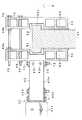
[格子型ベランダへの取り付け]
図2は、この実施の形態の衛星電波受信アンテナ装置を、格子型ベランダに取り付けた状態を示している。このときには、図2に示すように、アンテナ取り付け部材43は、側面43Aの貫通孔43a,43bを、取り付け片51の貫通孔51a,51bに合わせ、ボルト71とボルト72を、それらの貫通孔を通じて貫通させ、これらボルト71、72にナット81、82を装着して締め付けることにより、第1の固定用部材50に取り付ける。
【0036】
そして、長手方向を水平方向とした第1の固定用部材50と第2の固定用部材60とで、格子型ベランダの格子91、92を挟み、第1の固定用部材50と第2の固定用部材60の長手方向の適当な2か所の貫通孔、図2の例では、両端の貫通孔53a,61aと、貫通孔53h,61hとに、ボルト73、74を挿通し、これらボルト73、74にナット83、84を装着して締め付けることにより、アンテナ装置全体を格子91、92に固定するようにする。
【0037】
この場合、図2の例では、2本の格子91、92を挟む位置の2か所の貫通孔53a,61aと、貫通孔53h,61hの位置において、アンテナ装置全体を固定するようにしたが、2本の格子91、92の間の2か所の貫通孔53c,61cと、貫通孔53f,61fあるいは、53d,61dと、貫通孔53e,61eの位置において、アンテナ装置全体を固定するようにすることもできる。
【0038】
以上のように取り付け固定した後、方向角度調整機構42により、方位角および仰角を調整することにより、パラボラ反射板41を衛星方向に正しく方向調整して、取り付けが完了する。
【0039】
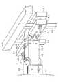
[壁型ベランダへの取り付け]
図3は、この実施の形態の衛星電波受信アンテナ装置を、壁型ベランダに取り付けた状態を示している。このときには、図3に示すように、アンテナ取り付け部材43は、側面43Bの貫通孔43c,43dを、取り付け片51の貫通孔51a,51bに合わせ、ボルト71とボルト72を、それらの貫通孔を通じて貫通させ、これらボルト71、72にナット81、82を装着して締め付けることにより、第1の固定用部材50に取り付ける。
【0040】
すなわち、この壁型ベランダに取り付けるときには、前述の格子型ベランダのときとは、アンテナ取り付け部材43を、その四角柱の中心線を回転中心として90度回転させて、第1の固定用部材50に対して取り付ける。
【0041】
そして、第1および第2の固定用部材50、60を、その長手方向が垂直方向となるようにして、図3に示すように、その長手方向の一端側で、コンクリート壁93を挟むようにする。このとき、凹段部54および62内に、壁型ベランダの上部の手摺部分93aが入り込むように、第1および第2の固定用部材50、60を装着する。
【0042】
第1および第2の固定用部材50、60には、上述のようなコンクリート壁93への装着に先立ち、コンクリート壁93への装着部分とは逆側の長手方向の他端部側の2か所の貫通孔にボルト75および76を挿通させる。この際に、外側(上側)のボルト75には、第1および第2の固定用部材50、60間の部分に2個のナット85a,85bを装着するようにする。内側(下側)のボルト76には、通常のように、貫通させたボルト先端部にナット86を装着するようにする。
【0043】
また、第1および第2の固定用部材50および60の長手方向の一端側のコンクリート壁93への装着部には、例えばゴムなどの弾性体のシート55および63を、例えば両面テープなどの接着材を用いて取り付けておく。
【0044】
そして、図3のように、第1および第2の固定用部材50および60を、コンクリート壁93に装着したら、上側のボルト75に装着されているナット85a,85bの位置をまず調整する。すなわち、ナット85bは、第2の固定用部材60側にしっかりと締め付けて固定する。一方、ナット85aは、第1および第2の固定用部材50および60間の距離が、コンクリート壁93の厚さにほぼ一致する位置にする。
【0045】
次に、下側のボルト76の先端に装着されているナット86を締め付ける。この締め付けにより、第1および第2の固定用部材50および60の長手方向の他端側には、梃子の原理により、コンクリート壁93を締め付けるような力が働く。こうして、この実施の形態の衛星電波受信アンテナ装置は、コンクリート壁からなるベランダにも装着固定が可能となる。この場合に、弾性シート55、63の存在により、アンテナ装置は、より確実にコンクリート壁93に固定されるものである。
【0046】
以上のように取り付け固定した後、方向角度調整機構42により、方位角および仰角を調整することにより、パラボラ反射板41を衛星方向に正しく方向調整して、取り付けが完了する。
【0047】
このとき、前述の格子型ベランダへの取り付けの場合に対して、第1および第2の固定用部材50、60は、90度回転した状態になるが、前述したように、このときには、アンテナ取り付け部材43が、90度回転した状態で第1の固定用部材50に取り付けられているので、方向角度調整機構42により、格子型ベランダに取り付けた場合と同様にして方向調整を行うことができる。
【0048】
[他の取り付け態様]
この実施の形態の衛星電波受信アンテナ装置の第1および第2の固定用部材50および60の中央部に設けられた凹段部54および62を利用することにより、この実施の形態の衛星電波受信アンテナ装置は、図4に示すように、円柱状の構造物94や角柱状の構造物部分にも、容易に固定することができる。この場合の第1および第2の固定用部材50および60の、取り付け対象物に対する取り付け状態は、図2に示した状態と同様で、取り付け対象物を挟む2か所の貫通孔にボルトを通し、ナットで締め付けることにより、固定することができる。
【0049】
この場合、取り付け対象物である円柱状構造物94や角柱状構造物は、水平方向のものであっても、垂直方向のものであっても、いずれでもよい。図4の例は、水平方向の円柱状の構造物に取り付けた状態を示しており、このため、第1の固定用部材50と、アンテナ取り付け部材43との結合関係は、図3のコンクリート壁に取り付ける場合と同様とされている。
【0050】
[変形例]
以上の実施の形態は、衛星電波受信アンテナ装置の場合であるが、アンテナ取り付け部材43に、従来のようなアンテナ支柱を取り付けるなどすることにより、受信アンテナ本体とは別体のアンテナ取り付け装置の構成とすることも、勿論できる。その場合においても、アンテナ取り付け装置は、格子型ベランダでも、コンクリート壁型のベランダであっても、取り付けが可能であるので、一つのアンテナ取り付け装置により、殆どのベランダに取り付け可能となるという顕著な効果がある。
【0051】
なお、上述の実施の形態では、固定用部材に設けた貫通孔は8個であったが、取り付け部材43の取り付け片51、52の部分の一方の側に2個(壁型ベランダへの取り付け用)と、他方の側に1個の、少なくとも3個を設けるようにすればよい。
【0053】
【発明の効果】
以上説明したように、この発明によれば、一般的なベランダの殆どのものに取り付け可能な衛星電波受信アンテナ装置を実現することができる。そして、アンテナ設置時には、専用の取り付け金具を用意する必要がないので、設置工事の際のコストおよび時間が大幅に削減することができる。
【0054】
また、アンテナ設置位置の変更や、引っ越しなどによる設置環境の変化にも柔軟に対応することができる。
【図面の簡単な説明】
【図1】この発明による衛星電波受信アンテナ装置の実施の形態のアンテナ取り付け装置部の部分を説明するための図である。
【図2】実施の形態の衛星電波受信アンテナ装置の取り付け状態の一態様を示す図である。
【図3】実施の形態の衛星電波受信アンテナ装置の取り付け状態の他の態様を示す図である。
【図4】実施の形態の衛星電波受信アンテナ装置の取り付け状態の他の態様を示す図である。
【図5】従来のアンテナ取り付け金具の一例を説明するための図である。
【図6】図5の例のアンテナ取り付け金具を用いた取り付け態様を示す図である。
【図7】従来のアンテナ取り付け金具の他の例を説明するための図である。
【図8】図7の例のアンテナ取り付け金具を用いた取り付け態様を示す図である。
【符号の説明】
40…アンテナ取り付け部分、41…パラボラ反射板、42…方向角度調整機構部、43…アンテナ取り付け部材、50…第1の固定用部材、60…第2の固定用部材、53a〜53h…貫通孔、61a〜61h…貫通孔、54、62…凹段部、91、92…格子型ベランダの格子、93…壁型ベランダのコンクリート壁、55、63…弾性シート[0001]
BACKGROUND OF THE INVENTION
The present invention relates to an antenna mounting device and a satellite radio wave receiving antenna device suitable for, for example, a satellite broadcast receiving antenna.
[0002]
[Prior art]
A satellite broadcast receiving antenna needs to directly receive radio waves from a satellite, and is often attached to an outdoor veranda because of the ease of antenna installation work. However, since there are a wide variety of veranda structures, such as a lattice type and a concrete wall type, when sold as a receiving antenna device including an attachment part to the veranda, the structure of the attachment part is In some cases, the antenna cannot be attached to the cable.
[0003]
For this reason, conventionally, the receiving antenna body and the antenna mounting apparatus are often sold separately. When mounting the receiving antenna to the veranda when sold separately in this way, first purchase an antenna mounting bracket as an antenna mounting device corresponding to the structure of the veranda to be installed, and then attach it to the veranda. I try to attach it to the bracket.
[0004]
FIG. 5 shows an example of a conventional
[0005]
Two through holes (not shown) for penetrating and attaching the
[0006]
As shown in FIG. 6, the
[0007]
After the fixing, the
[0008]
Recently, the number of verandas made of concrete walls is increasing from the viewpoint of privacy protection. However, the above-described
[0009]
The
[0010]
The connecting
[0011]
When the
[0012]
After the fixing, the
[0013]
[Problems to be solved by the invention]
As described above, conventionally, the satellite broadcast receiving antenna and the antenna mounting bracket are sold separately, and when mounting the satellite broadcasting receiving antenna to the veranda, it is necessary to purchase and use the antenna mounting bracket corresponding to the structure of the mounted veranda. was there.
[0014]
For this reason, when the antenna installation position is changed or the installation environment changes due to moving, a situation may arise in which the antenna mounting bracket must be newly purchased, which imposes an economical burden on the user. It will be.
[0015]
In addition, since the antenna body must be structured to be adapted to various antenna mounting brackets, for example, the antenna mounting bracket is provided with a fitting pipe, while the antenna body is inserted into the fitting pipe. There is a structural restriction that a support pipe must be attached, which is an obstacle to cost reduction as an antenna device.
[0016]
Also, when mounting an antenna, the antenna mounting bracket must first be mounted and fixed on the veranda, then the antenna body must be mounted, which requires a lot of mounting work, and many parts are used for mounting, making installation difficult. Was increasing.
[0017]
In view of the above points, the present invention provides an antenna mounting apparatus and a satellite radio wave receiving antenna apparatus that can be mounted on either a lattice-type veranda or a concrete wall-type veranda and that is advantageous in terms of cost. Objective.
[0018]
[Means for Solving the Problems]
In order to solve the above-described problem, an antenna mounting apparatus according to the present invention includes:
An antenna mounting member;
A first fixing member to which the antenna attachment member is attached;
Along with the first fixing member, a second fixing member for fixing the object to be attached,
First and second bolts;
A first set and a second set of nuts, eachset oftwo
Have
The antenna mounting member is
One end of the antenna is the mounting part of the antenna body that receives radio waves from the satellite.
The other end has a fixing portion that has the same shape even when rotated 90 degrees with respect to the first fixing member as a rotation center axis.
The first fixing member is:
On the surface opposite to the surface facing the second fixing member, there is a mounting portion for fixing the fixing portion of the antenna mounting member in a state where the antenna mounting member is rotated 90 degrees or not. And
The first and second fixing members are:
In the substantially central part in the longitudinal direction on the surface where they face, having a recess,
The first and second bolts are respectively penetrated to positions corresponding to each other in a state where the two fixing members face each other along one longitudinalend side in the longitudinal direction.Having first and second through holes of a size capable of
The first and second bolts are sized so that one of the first and second bolts can be penetrated to a position corresponding to each other with the two fixing members facing the other end side in the longitudinal direction. Each having three through holes,
Ina state where the antenna body is fixed by sandwiching an object to be attached by the other end side of the first and second fixing members,
The first and second bolts are provided on the first and second fixing members so as to penetrate the first and second through holes, respectively.
The first set of nuts is provided at a position corresponding to the thickness of the object to be attached, on the surface side where the first and second fixing members face the first bolt.
The second set of nuts is formed on the surface of the first and second fixing members opposite to the surface of the second bolt facing the first and second fixing members. The other end side is provided so as to sandwich the attachment object,
In a state where the antenna body is fixed by sandwiching an object to be attached by the central portions of the first and second fixing members,
The first and second bolts are provided in the first and second fixing members so as to penetrate one through hole and the third through hole of the first or second through hole, respectively. And
The nuts of the first set and the second set are arranged on the surface side opposite to the surface where the first and second fixing members face the first and second bolts. Two fixing members are provided so as to sandwich the attachment object.
An antenna mounting device.
It is what.
[0019]
According to the antenna attachment device of the present invention having the above-described configuration, the antenna attachment device can be attached to the veranda by setting the object to be attached as the upper part of the concrete wall type veranda in the first fixed state. Moreover, the antenna attachment device can be attached to the veranda by using the attachment object as the lattice portion of the lattice type veranda in the second fixed state. Therefore, according to the present invention, it is possible to attach to a wide variety of verandas with a single antenna attachment device.
[0020]
DETAILED DESCRIPTION OF THE INVENTION
Embodiments of the present invention will be described below with reference to the drawings. The embodiment described below is for a satellite broadcast receiving antenna device having an antenna mounting device section.
[0021]
FIG. 1 mainly shows the configuration of the antenna mounting device section of the satellite broadcast receiving antenna device of this embodiment. As shown in FIG. 1, the antenna attachment device portion of this embodiment is roughly composed of an
[0022]
First, the
[0023]
The
[0024]
The direction angle
[0025]
The two
[0026]
The
[0027]
The azimuth angle adjusting unit is configured by attaching the two
[0028]
The other end side of the
[0029]
The first fixing
[0030]
Further,
[0031]
The
[0032]
In this case, since the
[0033]
In addition, recessed
[0034]
Next, how the satellite radio wave receiving antenna apparatus having the antenna mounting apparatus having the above-described structure is mounted on a lattice type veranda or a concrete wall type veranda will be described.
[0035]
[Mounting on a grid type veranda]
FIG. 2 shows a state in which the satellite radio wave receiving antenna device of this embodiment is attached to a lattice type veranda. At this time, as shown in FIG. 2, the
[0036]
Then, the first fixing
[0037]
In this case, in the example of FIG. 2, the entire antenna device is fixed at the positions of the two through
[0038]
After mounting and fixing as described above, the direction
[0039]
[Mounting on a wall-type balcony]
FIG. 3 shows a state in which the satellite radio wave receiving antenna device of this embodiment is attached to a wall type veranda. At this time, as shown in FIG. 3, the
[0040]
That is, when attaching to the wall type veranda, the
[0041]
Then, as shown in FIG. 3, the first and second fixing
[0042]
Prior to mounting on the
[0043]
In addition,
[0044]
When the first and second fixing
[0045]
Next, the nut 86 attached to the tip of the
[0046]
After mounting and fixing as described above, the direction
[0047]
At this time, the first and second fixing
[0048]
[Other mounting modes]
By using the
[0049]
In this case, the
[0050]
[Modification]
Although the above embodiment is a case of a satellite radio wave receiving antenna device, a configuration of an antenna mounting device that is separate from the receiving antenna body by attaching a conventional antenna post to the
[0051]
In the above-described embodiment, the number of through holes provided in the fixing member is eight, but two on one side of the
[0053]
【The invention's effect】
As described above, according to the present invention, it is possible to realize a satellite radio wave receiving antenna device that can be attached to almost any general veranda. And since it is not necessary to prepare a special attachment bracket at the time of antenna installation, the cost and time at the time of installation construction can be reduced significantly.
[0054]
In addition, it is possible to flexibly cope with changes in the installation environment due to changes in the antenna installation position or moving.
[Brief description of the drawings]
FIG. 1 is a diagram for explaining a portion of an antenna attachment device portion of an embodiment of a satellite radio wave reception antenna device according to the present invention;
FIG. 2 is a diagram showing an aspect of a state in which the satellite radio wave receiving antenna device according to the embodiment is attached.
FIG. 3 is a diagram showing another aspect of the attached state of the satellite radio wave receiving antenna device of the embodiment.
FIG. 4 is a diagram showing another aspect of the attached state of the satellite radio wave receiving antenna device of the embodiment.
FIG. 5 is a view for explaining an example of a conventional antenna mounting bracket.
6 is a view showing a mounting mode using the antenna mounting bracket of the example of FIG.
FIG. 7 is a diagram for explaining another example of a conventional antenna mounting bracket.
FIG. 8 is a view showing a mounting mode using the antenna mounting bracket of the example of FIG.
[Explanation of symbols]
DESCRIPTION OF
Claims (3)
Translated fromJapanese前記アンテナ取り付け部材が取り付けられる第1の固定用部材と、
前記第1の固定用部材と共に、取り付け対象物を挟んで固定するための第2の固定用部材と、
第1および第2のボルトと、
2つ1組とされた第1組および第2組のナットと
を有し、
前記アンテナ取り付け部材は、
その一端が、衛星からの電波を受信するアンテナ本体の取り付け部とされ、
その他端が、前記第1の固定用部材に対して、垂直な方向を回転中心軸として90度回転させても同じ形状とされた固定部を有し、
前記第1の固定用部材は、
前記第2の固定用部材と対向する面とは反対側の面に、前記アンテナ取り付け部材を90度回転させた状態あるいは回転させない状態で、前記アンテナ取り付け部材の固定部を固定する取り付け部を有し、
前記第1および第2の固定用部材は、
それらが対向する面における長手方向のほぼ中央部に、凹部を有するとともに、
前記長手方向における一方の端部側に、その長手方向に沿って、これら2枚の固定用部材を対向させた状態において互いに対応した位置に、前記第1および第2のボルトをそれぞれ貫通させることができる大きさの第1および第2の貫通孔をそれぞれ有し、
前記長手方向における他方の端部側に、それら2枚の固定用部材を対向させた状態において互いに対応した位置に、前記第1および第2のボルトの一方を貫通させることのできる大きさの第3の貫通孔をそれぞれ有し、
前記第1および第2の固定用部材の前記他方の端部側により取り付け対象物を挟んで前記アンテナ本体を固定する状態では、
前記第1および第2のボルトは、前記第1および第2の貫通孔をそれぞれ貫通するように、前記第1および第2の固定用部材に設けられ、
前記第1組のナットは、前記第1のボルトに、前記第1および第2の固定用部材が対向する面側において、前記取り付け対象物の厚さに対応した位置に設けられるとともに、
前記第2組のナットは、前記第2のボルトに、前記第1および第2の固定用部材が対向する面とは反対側の面側において、前記第1および第2の固定用部材の前記他方の端部側が前記取り付け対象物を挟むように設けられ、
前記第1および第2の固定用部材の前記中央部により取り付け対象物を挟んで前記アンテナ本体を固定する状態では、
前記第1および第2のボルトは、前記第1あるいは第2の貫通孔の一方の貫通孔および前記第3の貫通孔をそれぞれ貫通するように、前記第1および第2の固定用部材に設けられ、
前記第1組および第2組のナットは、前記第1および第2のボルトに、前記第1および第2の固定用部材が対向する面とは反対側の面側において、前記第1および第2の固定用部材が前記取り付け対象物を挟むように設けられ
ようにしたアンテナ取り付け装置。An antenna mounting member;
A first fixing member to which the antenna attachment member is attached;
Along with the first fixing member, a second fixing member for fixing the object to be attached,
First and second bolts;
A first set and a second set of nuts, eachset oftwo
Have
The antenna mounting member is
One end of the antenna is the mounting part of the antenna body that receives radio waves from the satellite.
The other end has a fixing portion that has the same shape even when rotated 90 degrees with respect to the first fixing member as a rotation center axis.
The first fixing member is:
On the surface opposite to the surface facing the second fixing member, there is a mounting portion for fixing the fixing portion of the antenna mounting member in a state where the antenna mounting member is rotated 90 degrees or not. And
The first and second fixing members are:
In the substantially central part in the longitudinal direction on the surface where they face, having a recess,
The first and second bolts are respectively penetrated to positions corresponding to each other in a state where the two fixing members face each other along one longitudinalend side in the longitudinal direction.Having first and second through holes of a size capable of
The first and second bolts are sized so that one of the first and second bolts can be penetrated to a position corresponding to each other with the two fixing members facing the other end side in the longitudinal direction. Each having three through holes,
Ina state where the antenna body is fixed by sandwiching an object to be attached by the other end side of the first and second fixing members,
The first and second bolts are provided on the first and second fixing members so as to penetrate the first and second through holes, respectively.
The first set of nuts is provided at a position corresponding to the thickness of the object to be attached, on the surface side where the first and second fixing members face the first bolt.
The second set of nuts is formed on the surface of the first and second fixing members opposite to the surface of the second bolt facing the first and second fixing members. The other end side is provided so as to sandwich the attachment object,
In a state where the antenna body is fixed by sandwiching an object to be attached by the central portions of the first and second fixing members,
The first and second bolts are provided in the first and second fixing members so as to penetrate one through hole and the third through hole of the first or second through hole, respectively. And
The nuts of the first set and the second set are arranged on the surface side opposite to the surface where the first and second fixing members face the first and second bolts. Two fixing members are provided so as to sandwich the attachment object.
An antenna mounting device.
前記アンテナ取り付け部材が取り付けられる第1の固定用部材と、 A first fixing member to which the antenna attachment member is attached;
前記第1の固定用部材と共に、取り付け対象物を挟んで固定するための第2の固定用部材と、 Along with the first fixing member, a second fixing member for fixing the object to be attached,
第1および第2のボルトと、 First and second bolts;
2つ1組とされた第1組および第2組のナットと A first set and a second set of nuts, each set of two
を有し、Have
前記アンテナ取り付け部材は、 The antenna mounting member is
その一端が、衛星からの電波を受信するアンテナ本体の取り付け部とされ、 One end of the antenna is the mounting part of the antenna body that receives radio waves from the satellite.
その他端が、前記第1の固定用部材に対して、垂直な方向を回転中心軸として90度回転させても同じ形状とされた固定部を有し、 The other end has a fixing portion that has the same shape even when rotated 90 degrees with respect to the first fixing member as a rotation center axis.
前記第1の固定用部材は、 The first fixing member is:
前記第2の固定用部材と対向する面とは反対側の面に、前記アンテナ取り付け部材を90度回転させた状態あるいは回転させない状態で、前記アンテナ取り付け部材の固定部を固定する取り付け部を有し、 On the surface opposite to the surface facing the second fixing member, there is a mounting portion for fixing the fixing portion of the antenna mounting member in a state where the antenna mounting member is rotated 90 degrees or not. And
前記第1および第2の固定用部材は、 The first and second fixing members are:
それらが対向する面における長手方向のほぼ中央部に、凹部を有するとともに、 In the substantially central part in the longitudinal direction on the surface where they face, having a recess,
前記長手方向における一方の端部側に、その長手方向に沿って、これら2枚の固定用部材を対向させた状態において互いに対応した位置に、前記第1および第2のボルトをそれぞれ貫通させることができる大きさの第1および第2の貫通孔をそれぞれ有し、 The first and second bolts are respectively penetrated to positions corresponding to each other in a state where the two fixing members face each other along one longitudinal end side in the longitudinal direction. Having first and second through holes of a size capable of
前記長手方向における他方の端部側に、それら2枚の固定用部材を対向させた状態において互いに対応した位置に、前記第1および第2のボルトの一方を貫通させることのできる大きさの第3の貫通孔をそれぞれ有する The first and second bolts are sized so that one of the first and second bolts can be penetrated to a position corresponding to each other with the two fixing members facing the other end side in the longitudinal direction. 3 through holes each
ようにしたアンテナ取り付け装置により、前記アンテナ本体を前記取り付け対象物に固定するようにしたアンテナ取り付け方法であり、 An antenna mounting method in which the antenna body is fixed to the mounting object by the antenna mounting device.
前記第1および第2の固定用部材の前記他方の端部側により取り付け対象物を挟んで前記アンテナ本体を固定する状態では、 In a state where the antenna body is fixed by sandwiching an object to be attached by the other end side of the first and second fixing members,
前記第1および第2のボルトを、前記第1および第2の貫通孔をそれぞれ貫通するように、前記第1および第2の固定用部材に設け、 Providing the first and second bolts on the first and second fixing members so as to penetrate the first and second through holes, respectively;
前記第1組のナットを、前記第1のボルトに、前記第1および第2の固定用部材が対向する面側において、前記取り付け対象物の厚さに対応した位置に設けるとともに、 The first set of nuts is provided at a position corresponding to the thickness of the object to be attached on the surface side of the first bolt and the first and second fixing members facing each other.
前記第2組のナットを、前記第2のボルトに、前記第1および第2の固定用部材が対向する面とは反対側の面側において、前記第1および第2の固定用部材の前記他方の端部側が前記取り付け対象物を挟むように設け、 The second set of nuts on the surface of the first and second fixing members opposite to the surface on which the first and second fixing members face the second bolt. Provided so that the other end side sandwiches the attachment object,
前記第1および第2の固定用部材の前記中央部により取り付け対象物を挟んで前記アンテナ本体を固定する状態では、 In a state where the antenna body is fixed by sandwiching an object to be attached by the central portions of the first and second fixing members,
前記第1および第2のボルトを、前記第1あるいは第2の貫通孔の一方の貫通孔および前記第3の貫通孔をそれぞれ貫通するように、前記第1および第2の固定用部材に設け、 The first and second bolts are provided in the first and second fixing members so as to penetrate one through hole and the third through hole of the first or second through hole, respectively. ,
前記第1組および第2組のナットを、前記第1および第2のボルトに、前記第1および第2の固定用部材が対向する面とは反対側の面側において、前記第1および第2の固定用部材が前記取り付け対象物を挟むように設ける The first set and the second set of nuts are connected to the first and second bolts on the side of the surface opposite to the surface facing the first and second fixing members. Two fixing members are provided so as to sandwich the attachment object.
ようにしたアンテナ取り付け方法。 How to attach the antenna.
衛星電波受信アンテナ装置。 Satellite radio wave receiving antenna device.
Priority Applications (5)
| Application Number | Priority Date | Filing Date | Title |
|---|---|---|---|
| JP2000141630AJP4340827B2 (en) | 2000-05-15 | 2000-05-15 | ANTENNA MOUNTING DEVICE, ITS MOUNTING METHOD, AND SATELLITE RADIO RECEIVE ANTENNA DEVICE |
| MYPI20012053MY134233A (en) | 2000-05-15 | 2001-05-03 | Antenna installation device and satellite radio frequency receiver antenna device |
| US09/854,773US6469679B2 (en) | 2000-05-15 | 2001-05-14 | Antenna installation device and satellite radio frequency receiver antenna device |
| KR1020010026311AKR20010104675A (en) | 2000-05-15 | 2001-05-15 | Antenna installation device and satellite radio frequency receiver antenna device |
| CN01117668ACN1332488A (en) | 2000-05-15 | 2001-05-15 | Antenna mounting installation and antenna installation for satellite RF receiver |
Applications Claiming Priority (1)
| Application Number | Priority Date | Filing Date | Title |
|---|---|---|---|
| JP2000141630AJP4340827B2 (en) | 2000-05-15 | 2000-05-15 | ANTENNA MOUNTING DEVICE, ITS MOUNTING METHOD, AND SATELLITE RADIO RECEIVE ANTENNA DEVICE |
Publications (2)
| Publication Number | Publication Date |
|---|---|
| JP2001326510A JP2001326510A (en) | 2001-11-22 |
| JP4340827B2true JP4340827B2 (en) | 2009-10-07 |
Family
ID=18648716
Family Applications (1)
| Application Number | Title | Priority Date | Filing Date |
|---|---|---|---|
| JP2000141630AExpired - Fee RelatedJP4340827B2 (en) | 2000-05-15 | 2000-05-15 | ANTENNA MOUNTING DEVICE, ITS MOUNTING METHOD, AND SATELLITE RADIO RECEIVE ANTENNA DEVICE |
Country Status (5)
| Country | Link |
|---|---|
| US (1) | US6469679B2 (en) |
| JP (1) | JP4340827B2 (en) |
| KR (1) | KR20010104675A (en) |
| CN (1) | CN1332488A (en) |
| MY (1) | MY134233A (en) |
Families Citing this family (18)
| Publication number | Priority date | Publication date | Assignee | Title |
|---|---|---|---|---|
| JPWO2005076406A1 (en)* | 2004-02-06 | 2007-10-18 | 住友電気工業株式会社 | Luneberg lens antenna device |
| US7046210B1 (en)* | 2005-03-30 | 2006-05-16 | Andrew Corporation | Precision adjustment antenna mount and alignment method |
| US7086207B2 (en)* | 2005-06-09 | 2006-08-08 | Andrew Corporation | Antenna sector frame |
| US8819743B2 (en) | 2007-12-19 | 2014-08-26 | Dish Network L.L.C. | Transfer of data related to broadcast programming over a communication network |
| US8907862B2 (en)* | 2011-04-12 | 2014-12-09 | Dish Network L.L.C. | Apparatus and systems for mounting an electrical switching device |
| US9337545B2 (en)* | 2008-06-20 | 2016-05-10 | Dish Network L.L.C. | Apparatus and systems for mounting an electrical switching device |
| US8780008B2 (en) | 2008-06-20 | 2014-07-15 | Dish Network L.L.C. | Reinforced mount for an antenna assembly |
| US8462075B2 (en)* | 2010-02-23 | 2013-06-11 | Dish Network L.L.C. | Apparatus for mounting an object to a railing |
| US8646186B2 (en) | 2010-12-16 | 2014-02-11 | Dish Network L.L.C. | Multi-angle levels and plumbing methods |
| US8802985B2 (en) | 2011-09-07 | 2014-08-12 | Dish Network L.L.C. | In-wall extension apparatus |
| US9123987B2 (en) | 2012-07-31 | 2015-09-01 | Dish Network L.L.C. | Antenna mounting systems and methods |
| US9065172B2 (en)* | 2013-05-23 | 2015-06-23 | Commscope Technologies Llc | Mounting hub for antenna |
| JP6214033B2 (en)* | 2013-08-21 | 2017-10-18 | フルタ電機株式会社 | Blower mounting device |
| US9905905B1 (en)* | 2014-09-26 | 2018-02-27 | Tessco Communications Incorporated | Antenna enclosure for attachment to a handrail |
| US9553350B2 (en)* | 2015-05-14 | 2017-01-24 | Micro Wireless Solutions, Corp. | Antenna mount assembly |
| US9982836B2 (en)* | 2016-03-21 | 2018-05-29 | Worldvu Satellites Limited | User terminal clamp |
| CN108987883B (en)* | 2017-06-02 | 2020-05-08 | 华为技术有限公司 | Antenna information sensing unit mounting bracket, antenna information sensing unit and antenna system |
| JP1688766S (en)* | 2020-06-26 | 2021-06-28 |
Family Cites Families (4)
| Publication number | Priority date | Publication date | Assignee | Title |
|---|---|---|---|---|
| JP3667423B2 (en)* | 1996-02-26 | 2005-07-06 | 富士通株式会社 | Antenna device |
| JP3047856B2 (en)* | 1997-05-12 | 2000-06-05 | 日本電気株式会社 | Antenna direction adjustment device |
| SE513164C2 (en)* | 1998-03-03 | 2000-07-17 | Allgon Ab | mounting bracket |
| US6262691B1 (en)* | 1999-09-16 | 2001-07-17 | Endgate Corporation | Antenna mounting assembly with installation tool |
- 2000
- 2000-05-15JPJP2000141630Apatent/JP4340827B2/ennot_activeExpired - Fee Related
- 2001
- 2001-05-03MYMYPI20012053patent/MY134233A/enunknown
- 2001-05-14USUS09/854,773patent/US6469679B2/ennot_activeExpired - Fee Related
- 2001-05-15KRKR1020010026311Apatent/KR20010104675A/ennot_activeWithdrawn
- 2001-05-15CNCN01117668Apatent/CN1332488A/enactivePending
Also Published As
| Publication number | Publication date |
|---|---|
| CN1332488A (en) | 2002-01-23 |
| US6469679B2 (en) | 2002-10-22 |
| JP2001326510A (en) | 2001-11-22 |
| MY134233A (en) | 2007-11-30 |
| KR20010104675A (en) | 2001-11-26 |
| US20020003504A1 (en) | 2002-01-10 |
Similar Documents
| Publication | Publication Date | Title |
|---|---|---|
| JP4340827B2 (en) | ANTENNA MOUNTING DEVICE, ITS MOUNTING METHOD, AND SATELLITE RADIO RECEIVE ANTENNA DEVICE | |
| US4595165A (en) | Adjustable anchoring assembly | |
| US7460081B2 (en) | Apparatus and method for mounting a satellite dish to a pole | |
| JP3426444B2 (en) | Outer wall plate mounting structure | |
| US6709184B1 (en) | Apparatus for mounting a receiver mast and associated method | |
| US10648614B2 (en) | Satellite antenna mounting systems and methods | |
| PL183012B1 (en) | System for assembling and securing lining elements | |
| JP4426043B2 (en) | Antenna support device | |
| US20070273598A1 (en) | Luneberg Lens Antenna Device | |
| JPH1188018A (en) | Multi-antenna attachment metal fixture | |
| JPH0138965Y2 (en) | ||
| JP2611806B2 (en) | Building rooftop antenna pole establishment device | |
| JP2020180465A (en) | Eaves | |
| JPH0316362Y2 (en) | ||
| JP3250520U (en) | Earthquake-resistant reinforcement brackets | |
| JP2604952Y2 (en) | Veranda mounting antenna | |
| JPH0644212U (en) | Mast mounting structure | |
| JP4170553B2 (en) | Antenna mounting device | |
| JP4210491B2 (en) | Parabolic antenna support device | |
| JPH052419U (en) | Satellite broadcasting receiving antenna device | |
| JPH0316360Y2 (en) | ||
| JP4170645B2 (en) | Mounting structure of radio wave absorption panel | |
| KR200277744Y1 (en) | Flat side antenna | |
| JP5198041B2 (en) | Beam outer wall connection structure | |
| JP2514740B2 (en) | Nose cover material mounting structure |
Legal Events
| Date | Code | Title | Description |
|---|---|---|---|
| A621 | Written request for application examination | Free format text:JAPANESE INTERMEDIATE CODE: A621 Effective date:20061212 | |
| A977 | Report on retrieval | Free format text:JAPANESE INTERMEDIATE CODE: A971007 Effective date:20090402 | |
| A131 | Notification of reasons for refusal | Free format text:JAPANESE INTERMEDIATE CODE: A131 Effective date:20090408 | |
| A521 | Request for written amendment filed | Free format text:JAPANESE INTERMEDIATE CODE: A523 Effective date:20090522 | |
| TRDD | Decision of grant or rejection written | ||
| A01 | Written decision to grant a patent or to grant a registration (utility model) | Free format text:JAPANESE INTERMEDIATE CODE: A01 Effective date:20090610 | |
| A01 | Written decision to grant a patent or to grant a registration (utility model) | Free format text:JAPANESE INTERMEDIATE CODE: A01 | |
| A61 | First payment of annual fees (during grant procedure) | Free format text:JAPANESE INTERMEDIATE CODE: A61 Effective date:20090623 | |
| FPAY | Renewal fee payment (event date is renewal date of database) | Free format text:PAYMENT UNTIL: 20120717 Year of fee payment:3 | |
| FPAY | Renewal fee payment (event date is renewal date of database) | Free format text:PAYMENT UNTIL: 20120717 Year of fee payment:3 | |
| LAPS | Cancellation because of no payment of annual fees |