JP4340400B2 - Packet transfer method in layered packet network, layered packet communication system, edge node and mobile terminal used in the system, and packet transfer method in layered packet network - Google Patents
Packet transfer method in layered packet network, layered packet communication system, edge node and mobile terminal used in the system, and packet transfer method in layered packet networkDownload PDFInfo
- Publication number
- JP4340400B2 JP4340400B2JP2001174698AJP2001174698AJP4340400B2JP 4340400 B2JP4340400 B2JP 4340400B2JP 2001174698 AJP2001174698 AJP 2001174698AJP 2001174698 AJP2001174698 AJP 2001174698AJP 4340400 B2JP4340400 B2JP 4340400B2
- Authority
- JP
- Japan
- Prior art keywords
- packet
- node
- cache
- information
- mobile terminal
- Prior art date
- Legal status (The legal status is an assumption and is not a legal conclusion. Google has not performed a legal analysis and makes no representation as to the accuracy of the status listed.)
- Expired - Fee Related
Links
Images


Classifications
- H—ELECTRICITY
- H04—ELECTRIC COMMUNICATION TECHNIQUE
- H04L—TRANSMISSION OF DIGITAL INFORMATION, e.g. TELEGRAPHIC COMMUNICATION
- H04L45/00—Routing or path finding of packets in data switching networks
- H04L45/02—Topology update or discovery
- H04L45/04—Interdomain routing, e.g. hierarchical routing
- H—ELECTRICITY
- H04—ELECTRIC COMMUNICATION TECHNIQUE
- H04W—WIRELESS COMMUNICATION NETWORKS
- H04W36/00—Hand-off or reselection arrangements
- H04W36/0005—Control or signalling for completing the hand-off
- H04W36/0011—Control or signalling for completing the hand-off for data sessions of end-to-end connection
- H04W36/0019—Control or signalling for completing the hand-off for data sessions of end-to-end connection adapted for mobile IP [MIP]
- H—ELECTRICITY
- H04—ELECTRIC COMMUNICATION TECHNIQUE
- H04W—WIRELESS COMMUNICATION NETWORKS
- H04W40/00—Communication routing or communication path finding
- H04W40/02—Communication route or path selection, e.g. power-based or shortest path routing
- H04W40/20—Communication route or path selection, e.g. power-based or shortest path routing based on geographic position or location
- H—ELECTRICITY
- H04—ELECTRIC COMMUNICATION TECHNIQUE
- H04W—WIRELESS COMMUNICATION NETWORKS
- H04W8/00—Network data management
- H04W8/02—Processing of mobility data, e.g. registration information at HLR [Home Location Register] or VLR [Visitor Location Register]; Transfer of mobility data, e.g. between HLR, VLR or external networks
- H04W8/08—Mobility data transfer
- H04W8/085—Mobility data transfer involving hierarchical organized mobility servers, e.g. hierarchical mobile IP [HMIP]
- H—ELECTRICITY
- H04—ELECTRIC COMMUNICATION TECHNIQUE
- H04W—WIRELESS COMMUNICATION NETWORKS
- H04W36/00—Hand-off or reselection arrangements
- H—ELECTRICITY
- H04—ELECTRIC COMMUNICATION TECHNIQUE
- H04W—WIRELESS COMMUNICATION NETWORKS
- H04W36/00—Hand-off or reselection arrangements
- H04W36/0005—Control or signalling for completing the hand-off
- H04W36/0011—Control or signalling for completing the hand-off for data sessions of end-to-end connection
- H04W36/0027—Control or signalling for completing the hand-off for data sessions of end-to-end connection for a plurality of data sessions of end-to-end connections, e.g. multi-call or multi-bearer end-to-end data connections
- H—ELECTRICITY
- H04—ELECTRIC COMMUNICATION TECHNIQUE
- H04W—WIRELESS COMMUNICATION NETWORKS
- H04W40/00—Communication routing or communication path finding
- H04W40/34—Modification of an existing route
- H04W40/36—Modification of an existing route due to handover
- H—ELECTRICITY
- H04—ELECTRIC COMMUNICATION TECHNIQUE
- H04W—WIRELESS COMMUNICATION NETWORKS
- H04W64/00—Locating users or terminals or network equipment for network management purposes, e.g. mobility management
- H—ELECTRICITY
- H04—ELECTRIC COMMUNICATION TECHNIQUE
- H04W—WIRELESS COMMUNICATION NETWORKS
- H04W8/00—Network data management
- H04W8/02—Processing of mobility data, e.g. registration information at HLR [Home Location Register] or VLR [Visitor Location Register]; Transfer of mobility data, e.g. between HLR, VLR or external networks
- H04W8/04—Registration at HLR or HSS [Home Subscriber Server]
- H—ELECTRICITY
- H04—ELECTRIC COMMUNICATION TECHNIQUE
- H04W—WIRELESS COMMUNICATION NETWORKS
- H04W80/00—Wireless network protocols or protocol adaptations to wireless operation
- H04W80/04—Network layer protocols, e.g. mobile IP [Internet Protocol]
Landscapes
- Engineering & Computer Science (AREA)
- Computer Networks & Wireless Communication (AREA)
- Signal Processing (AREA)
- Databases & Information Systems (AREA)
- Mobile Radio Communication Systems (AREA)
- Data Exchanges In Wide-Area Networks (AREA)
Description
Translated fromJapanese【0001】
【発明の属する技術分野】
本発明は、階層化パケット網におけるパケット転送方法並びに階層化パケット通信システム並びに同システムに使用されるエッジノード及び移動端末並びに階層化パケット網におけるパケット転送方法に関し、特に、MIPv6(Mobile Internet Protocol version 6)等に準拠したパケット網に用いて好適な技術に関する。
【0002】
【従来の技術】
近年、IETF(Internet Engineering Task Force)において、インターネットプロトコル(IP)上で携帯電話等の移動端末(以下、単に「端末」ともいう)の位置を管理する方式として、「MIPv6」が提案されている。
図63に「MIPv6」に準拠したパケット通信システムの一例を示す。この図63に示すシステムでは、ルータ網(パケット網)110を運営するISP(Internet Service Provider)等(以下、単に「プロバイダ」という)が管理するホームエージェント(HA:Home Agent)ノード100において、そのプロバイダが提供するパケット転送サービスの契約加入者の移動端末(これを「ホーム端末」あるいは「契約端末」という)500の現在位置が管理される。
【0003】
同様に、HAノード100(ルータ網110)のプロバイダとは異なるプロバイダが管理するHAノード〔HAノード100側からみれば外部(foreign)網210のHAノード〕200では、ルータ網210についての契約端末の現在位置が管理される。なお、300,400はルータ網110,210間を結ぶ中継ルータ網を表す。
【0004】
ここで、具体的に、上記の契約端末500の現在位置管理は、契約端末500が契約ルータ網(ホーム網)110に存在している場合、その現在位置からアクセスしうる最寄りのアクセスノード(在圏ノード;無線基地局としての機能を有するパケットのラストホップルータ)111から広告(報知)される情報〔ルータ広告(RA:Router Advertisment)メッセージ〕に含まれるアクセスノード111のIPアドレスを基にCOA(Care of Address)と呼ばれる、現在自己がどのノードの在圏ゾーンに位置しているか(つまり、端末500の接続先ノード)を表す情報を作成し、これをHAノード100に通知することで実施される。
【0005】
一方、契約端末500がその移動により非契約ルータ網(移動先網)210に存在している場合(いわゆる「ローミング」中の場合)には、契約端末500は、移動先網210の最寄りのアクセスノード211から受信されるRAに含まれるアクセスノード211のIPアドレスを基にCOAを作成して、これをホーム網110のHAノード100にルータ網210,300,400を介して通知することになる。
【0006】
つまり、契約端末500は、その移動によって受信するRAに含まれるIPアドレスが変化して最寄りのアクセスノード111又は211が変わる度に、新たなCOAを作成してホーム網110のHAノード100に対して現在位置の更新登録を実施するのである。
これにより、HAノード100は、契約端末500が非契約ルータ網210に位置する場合(「ローミング」中の場合)であっても、逐次、更新登録されている現在位置宛に契約端末500宛のパケットをカプセル化(契約端末500宛のパケットにCOAを宛先アドレスとするヘッダを付加)して転送することで、契約端末500宛のパケットを正しく契約端末500に届けることができ、正常な移動通信が実現される。
【0007】
なお、ルータ網210についての契約端末によるHAノード200に対する位置登録手順も上記と同様である。
しかしながら、このような位置登録手順では、端末はその移動により最寄りのアクセスノードが変わる度に常にHAノード100又は200に位置登録を行なわなければならないため、現在位置とHAノード100(又は200)との距離に応じたパケット転送遅延が生じ、高速ハンドオーバには不向きである。また、アクセスノード211(又は111)からHAノード100(又は200)までのルータ網210,300,400,110のトラフィック量の増大にもつながる。
【0008】
なお、上記のシステムにおいてローミング中の契約端末(以下、ローミング端末という)500と相手端末600(移動端末でもよいし固定端末でもよい)との通信が開始された後は、例えば図64に示すように、ローミング端末500が、HAノード100に対する位置登録と同様に、相手端末600に現在のCOAを通知する(破線矢印700参照)ことで、「ルート最適化」を図ることができる。つまり、相手端末600は、現在のCOAをローミング端末500から直接受信することで、HAノード100を経由せずにそのCOA宛に直接パケットを送信することができるようになるのである(実線矢印800参照)。
【0009】
ただし、この場合も、ローミング端末500が移動して最寄りのアクセスノード211が変わったときには、その都度、新しいCOAを相手端末600に通知する必要があるため、相手端末600との距離に応じたパケット転送遅延によってハンドオーバ品質が左右されることになり、やはり高速ハンドオーバには向かない。
【0010】
このように、図63に示すような通常の「MIPv6」網(パケット通信システム)では、ローミング先のルータ網210でローミング端末500が移動すると、その移動の度(正確には、最寄りのアクセスノードが変わる度)に、HAノード100への位置登録が発生し、ハンドオーバ時の通信品質劣化を生じるが、これを緩和するために、近年、ルータ網を階層化して階層内の移動時にはHAノードへの位置登録を不要とする方式〔階層化(Hierarchical)MIPv6〕も提案されている。
【0011】
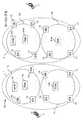
図65に階層化Mobile-IPv6(以下、「HMIPv6」と表記する)に準拠したパケット通信システムの一例を示す。この図65において、900が移動端末500へのゲート機能を提供するゲートノード(MA;Mobility Agent)であり、この図65に示すように、それぞれが1台以上のアクセスノードを収容することにより、ルータ網110又は210のMA900単位での階層化が図られている。
【0012】
そして、例えば、ルータ網110をホーム網とする契約端末500がホーム網110からローミング先のルータ網210へ移動(ローミングイン)すると(矢印903参照)、その端末500は、最寄りのMA900からルータ広告(RA)メッセージ(以下、単に「ルータ広告」ともいう)を受けて、そのMA900配下で使用するローカルなIPアドレス(「PCOA」と呼ばれる)と、HAノード100からMA900まで到達可能なIPアドレス(「VCOA」と呼ばれる)の2つのアドレスを作成する。
【0013】
その後、端末500は、「VCOA」をHAノード100に通知して現在位置の位置登録を行なう(矢印904参照)とともに、「PCOA」をMA900に通知してMA900にも位置登録を行なう(矢印905参照)。以降、端末500は、同一MA900の配下での移動の場合(矢印901参照)には、MA900にのみ位置登録を行ない(矢印906参照)、HAノード100への位置登録は行なわず、MA900が異なる地域へ移動した場合(矢印902参照)には、再度、移動先のMA900とHAノード100の両方に位置登録を行なう(矢印907,908参照)。なお、端末500は、ホーム網110内に位置する場合にも、MAをまたぐ移動が生じると、その都度、移動先のMA900とHAノード100の双方に位置登録を行なう。
【0014】
つまり、「HMIPv6」準拠のパケット通信システム(以下、階層化パケット通信システムという)では、同一MA900内の移動であれば、端末500は自己の現在位置の登録先(MA900)を切り替えないのである。したがって、図63及び図64により前述した通常のシステムよりも、高速なハンドオーバを実現できる。
【0015】
なお、この階層化パケット通信システムにおいても、前述したような「ルート最適化」を行なう場合には、図66に示すように、ローミング端末500が、相手端末600との通信開始後、相手端末600に現在の「VCOA」を通知すればよい(破線矢印909参照)。
つまり、相手端末600から最初に端末500宛に送信されたパケットが、一旦、HAノード100で受信され(矢印910参照)、HAノード100にて「VCOA」(MAアドレス)でカプセル化されてMA900へルーティングされ、そのMA900にて「PCOA」(移動先アドレス)でカプセル化されて該当アクセスノード211へルーティングされることにより、相手端末600とローミング端末500との通信が開始されるが、その後は、ローミング端末500が、相手端末600に「VCOA」(MA900まで到達可能なアドレス)を通知することにより、相手端末600は、その「VCOA」宛にパケットを送信することが可能となり、当該パケットはMA900まで到達できる。
【0016】
ただし、この場合も、ローミング端末500の移動によりMA900が変わる(「VCOA」が変わる)場合には、その都度、新しい「VCOA」を相手端末600に再通知する必要がある。なお、「ルート最適化」前の相手端末600からローミング端末500までのパケット転送ルートの一例を図67に、「ルート最適化」後の相手端末600からローミング端末500までのパケット転送ルートの一例を図68にそれぞれ示す。なお、これらの図67,図68において、符号110a,110b(210a,210b)はそれぞれMA900が管轄する階層化網を表し、これらの階層化網110a,110b(210a,210b)によってホーム網110(移動先網210)が形成されていることを示している。
【0017】
そして、これらの図67,図68から分かるように、階層化パケット通信システムでは、HAノード100に「VCOA」を通知することで、常に、端末500が位置登録(「PCOA」の通知)を行なっているMA900までのルートが最短距離となるよう最適化される(換言すれば、階層化パケット通信システムにおける「ルート最適化」では、必然的に、最低1台のMA900を経由することになる)。
【0018】
ところで、従来の「Mobile-IP」網におけるハンドオーバ方法には、「スムースハンドオーバ」と呼ばれるものがある。これは、例えば図69に模式的に示すように、HA100(200)に「COA1」が登録されている状態で、端末500が移動して接続先ルータが「R1」から「R2」に変わることにより新しい「COA2」を作成したときに、HA100(200)ではなく、移動直前の接続先ルータ「R2」に対して、新しい「COA2」宛にパケットを転送するよう要求(「COA2」を登録)する(これをスムースハンドオフ指示という;矢印912参照)ことで実現される。
【0019】
即ち、この図69において、「スムースハンドオフ指示」を受けた(端末500により「COA2」が登録された)ルータ「R1」は、HA100(200)にて「COA1」宛にカプセル化されて転送されてくる、相手端末(CN;Corresponding Node)600が端末500のホームアドレス宛に送信したパケットを受信すると(矢印910,911参照)、その受信パケットをさらに「COA2」宛にカプセル化して転送するのである。
【0020】
これにより、端末500が通信中に旧ルート(ルータ「R1」)へ到着したパケットは「スムースハンドオフ指示」によって新しい「COA2」へと転送されることになり(矢印913参照)、端末500は相手端末600との通信を円滑に継続することが可能になる。なお、HA100(200)のCOAが更新された後は、HA100(200)において最新のCOA宛への受信パケットのカプセル化が行なわれて、HA100(200)から新しい接続先ルータ「R2」経由で端末500にパケットが到着することとなる。
【0021】
【発明が解決しようとする課題】
しかしながら、図65〜図68により上述した階層化パケット通信システムでは、ハンドオーバ時間は短縮されるが、通常のパケット通信システムでは実現できていたルート最適化が、必ず現在使用中(位置登録を行なっている)MA900を経由しなければならないというルート上の制限が生じるために実現できなくなっている。換言すれば、階層化パケット通信システムにおいては、「ルート最適化」がMA900までしか行なわれないのである。このため、特定のMA900にパケットが集中して到着することになり、MA900の処理負荷も高くなってしまう。
【0022】
また、階層化パケット通信システムにおいても、端末500がMA900をまたいで移動する場合には、ホーム網110のHAノード100に位置登録を行なう必要があるため、通常の(非階層化)パケット通信システムと同様に、ハンドオーバに時間がかかり、高速ハンドオーバには向かない。
さらに、上述したハンドオーバ手法では、どの種別のパケットに対しても同じ動作をする。一般に、パケットは、どのような上位アプリケーションデータを運ぶかによって、それぞれネットワークに対して要求する特性が異なる。例えば、音声パケットであれば、高品質を保つために遅延を少なく押さえなければならないが、多少のパケットロスは許容できる。これに対し、データパケットの場合は、パケットロスが上位アプリケーションデータの再送処理を引き起こし通信品質に大きな影響を与えることになるが、転送遅延については多少生じても許容できる。
【0023】
このように、パケット種別(例えば、音声パケットやデータパケット等)によってネットワークに要求される条件が異なるにもかかわらず、これまでハンドオーバの仕組みはネットワークで1つの手法が固定的に適用されることが一般的であり、条件の異なるハンドオーバが同一ネットワークにおいて適用されることはなかった。その結果、音声向け、あるいは、データ通信向けのどちらかにチューニングしたハンドオーバ手法しか採用できないこととなり、双方の要求を柔軟に満たすことができなかった。
【0024】
本発明は、このような課題に鑑み創案されたもので、階層化パケット通信システムにおいて、ハンドオーバの高速対応とパケット転送ルートに制限の無いルート最適化とを可能にすることを目的とする。また、本発明は、受信パケット種別に応じてハンドオーバ手法を変更できるようにして、受信パケット種別に最適なハンドオーバを実現できるようにすることも目的とする。
【0025】
【課題を解決するための手段】
上記の目的を達成するために、本発明の階層化パケット網におけるパケット転送方法は、移動端末と通信してパケットの送受を行ないうる複数のエッジノードと、該移動端末の現在位置情報を管理し当該現在位置情報に基づいて該移動端末宛のパケットを該移動端末がその現在位置から通信可能なエッジノード(以下、在圏エッジノードという)へルーティングしうるゲートノードとをそなえて成る階層化パケット網において、
(1)ゲートノードが、自己が管理する移動端末の現在位置情報をキャッシュ情報として上記移動端末宛のパケットを自己宛にルーティングしてくるエッジノード(以下、通信中エッジノードという)に通知し、
(2)その通信中エッジノードが、通知されたキャッシュ情報に基づき上記ゲートノードに代わって上記移動端末宛のパケットの在圏エッジノードに対するルーティングを実施することを特徴としている。
【0026】
ここで、上記のエッジノードは、それぞれ、少なくとも自己を収容するゲートノードの識別情報(以下、ゲートノード識別情報という)と階層化パケット網の識別情報(以下、網識別情報という)とを含む報知情報を該移動端末に送信し、移動端末は、その報知情報に含まれるゲートノード識別情報が自己の移動に伴って変化しても網識別情報が変化していなければ、自己の現在位置情報の登録先を、前記自己の移動前のゲートノードに維持するようにしてもよい。
【0027】
次に、本発明の階層化パケット通信システムは、移動端末,ゲートノード,エッジノードがそれぞれ下記の手段をそなえていることを特徴としている。
・移動端末
(1)在圏エッジノードの識別情報に基づく位置情報を自己の現在位置情報として特定のゲートノードに通知して登録する現在位置登録手段
・ゲート ノード
(2)上記の移動端末の現在位置登録手段によって通知される現在位置情報を管理する端末位置管理手段
(3)この端末位置管理手段で管理されている現在位置情報をキャッシュ情報として通信中エッジノードに通知するキャッシュ情報通知手段
・エッジノード
(4)上記のゲートノードのキャッシュ情報通知手段により通知されたキャッシュ情報を保持するキャッシュ手段
(5)このキャッシュ手段に保持されているキャッシュ情報に基づき上記のゲートノードに代わって移動端末宛のパケットの在圏エッジノードに対するルーティングを実施するルーティング手段
加えて、上記階層化パケット通信システムは、前記エッジノードが、それぞれ、少なくとも自己を収容するゲートノードの識別情報と該階層化パケット網の識別情報とを含む報知情報を該移動端末に送信し、前記移動端末が、該報知情報に含まれる該ゲートノード識別情報が自己の移動に伴って変化しても該網識別情報が変化していなければ、自己の現在位置情報の登録先を、前記自己の移動前の該ゲートノードに維持するように構成されてもよい。
また、本発明に関連する技術の階層化パケット通信システムに使用されるゲートノードは、
(1)移動端末からその現在位置情報として通知されてくる、在圏エッジノードの識別情報に基づく位置情報を管理する端末位置管理手段と、
(2)この端末位置管理手段で管理されている現在位置情報をキャッシュ情報として通信中エッジノードに通知するキャッシュ情報通知手段とをそなえていることを特徴としている。
【0028】
さらに、本発明の階層化パケット通信システムに使用されるエッジノードは、
(1)ゲートノードで管理されている、在圏エッジノードの識別情報に基づく位置情報をキャッシュ情報として受けて保持するキャッシュ手段と、
(2)このキャッシュ手段に保持されているキャッシュ情報に基づき上記のゲートノードに代わって移動端末宛のパケットの在圏エッジノードに対するルーティングを実施するルーティング手段とをそなえていることを特徴としている。
加えて、上記階層化パケット通信システムに使用されるエッジノードは、前記エッジノードが、それぞれ、少なくとも自己を収容するゲートノードの識別情報と該階層化パケット網の識別情報とを含む報知情報を該移動端末に送信し、前記移動端末が、該報知情報に含まれる該ゲートノード識別情報が自己の移動に伴って変化しても該網識別情報が変化していなければ、自己の現在位置情報の登録先を、前記自己の移動前の該ゲートノードに維持するように構成されてもよい。
【0029】
また、本発明の階層化パケット通信システムに使用される移動端末は、
(1)少なくとも在圏エッジノードを収容する特定のゲートノードの識別情報(以下、ゲートノード識別情報という)と階層化パケット網の識別情報(以下、網識別情報という)とを含む報知情報を、在圏エッジノードから受信する報知情報受信手段と、
(2)この報知情報受信手段で受信された報知情報に含まれるゲートノード識別情報が自己の移動に伴って変化しても上記の網識別情報が変化していなければ、自己の現在位置情報の登録先を、前記自己の移動前のゲートノードに維持する現在位置登録手段とをそなえていることを特徴としている。
【0030】
次に、本発明に関連する技術のパケット網におけるハンドオーバ方法は、特定のルーティングノード(以下、特定ノードという)において移動端末の移動に伴う複数の端末位置情報を管理しておき、その特定ノードが、移動端末宛の受信パケットの種別(以下、パケット種別という)を識別し、識別したパケット種別に応じて上記複数の端末位置情報のいずれかを選択し、選択した端末位置情報に基づいて受信パケットをルーティングすることを特徴としている。
【0031】
ここで、上記の特定ノードは、上記複数の端末位置情報として、移動端末の現在の位置情報と、その移動端末の通信開始時の位置情報とを管理しておき、上述のごとく識別したパケット種別がパケットロスを許容する特性をもつパケット種別であると、移動端末の現在の位置情報を選択する一方、識別したパケット種別がパケット転送遅延を許容する特性をもつパケット種別であると、移動端末の通信開始時の位置情報を選択してもよい。
【0032】
また、本発明の階層化パケット網におけるパケット転送方法は、階層化パケット網において、ゲートノードが、自己が管理する移動端末の現在の位置情報をキャッシュ情報としてその移動端末宛のパケットを自己宛にルーティングしてくるルーティングノード(以下、通信中ノードという)に通知し、その通信中ノードは、上記の移動端末の通信開始時の位置情報を管理しておき、その移動端末宛の受信パケットの種別(以下、パケット種別という)を識別し、識別したパケット種別がパケットロスを許容する特性をもつパケット種別であると、ゲートノードから通知されたキャッシュ情報に基づきそのゲートノードに代わって受信パケットを在圏ノードへルーティングし、該ルーティングノードが、それぞれ、少なくとも自己を収容するゲートノードの識別情報(以下、ゲートノード識別情報という)と該階層化パケット網の識別情報(以下、網識別情報という)とを含む報知情報を該移動端末に送信し、該移動端末は、該報知情報に含まれる該ゲートノード識別情報が自己の移動に伴って変化しても該網識別情報が変化していなければ、自己の現在位置情報の登録先を、前記自己の移動前の該ゲートノードに維持することを特徴としている。
【0033】
さらに、本発明に関連する技術のルーティングノードは、移動端末の移動に伴う複数の端末位置情報を管理する端末位置管理手段と、その移動端末宛の受信パケットの種別(以下、パケット種別という)を識別するパケット種別識別手段と、このパケット種別識別手段で識別したパケット種別に応じて上記の端末位置管理手段で管理されている複数の端末位置情報のいずれかを選択する選択手段と、この選択手段によって選択された端末位置情報に基づいて受信パケットをルーティングするルーティング手段とをそなえたことを特徴としている。
【0034】
【発明の実施の形態】
以下、図面を参照して本発明の実施の形態を説明する。
(A)第1実施形態の説明
(A1)システム構成の概要説明
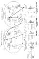
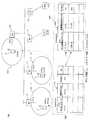
図1は本発明の第1実施形態としての階層化パケット通信システムの構成を示すブロック図で、この図1に示す階層化パケット通信システムは、「MIPv6」に準拠したシステムであって、それぞれ異なるキャリア(ISP等の通信事業者)が提供するパケット網(キャリア網ともいう)1,2を有しており、キャリア網1(2)は、少なくとも1台のVHA(Virtual Home Agent)ノード10(20)と、キャリア網1(2)を構成するサブキャリア(サブパケット)網1a,1b(2a,2b)毎に少なくとも1台ずつ設けられたTHA(Temporary Home Agent)ノード11a,11b(21a,21b)と、階層化網1a,1b(2a,2b)を形成する複数のエッジノード(EN)12とをそなえて構成されている。なお、「キャリア網」はいわゆる「ドメイン」として識別される。また、以下の説明において、本発明が適用されるキャリア網を「M3対応網」あるいは「M3v6(Multi-Media Mobile Network based on IPv6)ネットワーク」と称することがある。
【0035】
ここで、VHAノード10(20)は、自キャリア網(ホーム網)1(2)内に存在する契約加入者の移動端末(MN:Mobile Node)3(以下、「ホーム端末3」もしくは単に「端末3」という場合がある)の現在位置情報〔COA(VCOA,PCOA)〕を結合(バインディング)キャッシュ(Binding Cache)と呼ばれる情報の一部として管理するとともに、到着(受信)した端末3宛のパケットが示す宛先アドレス(DA)に対応する「COA」を本「キャッシュ」において検索し、該当「COA」でカプセル化して転送(ルーティング)するためのものである。
【0036】
なお、上記の「VCOA」/「PCOA」は、後述するように、THAアドレス/ENアドレスのネットワークプレフィックス部分(上位64ビット)と端末3のインタフェースIDとを組み合わせることにより作成される。従って、「VCOA」は該当THA11a,11b(21a,21b)まで到達できるアドレスを表し、「PCOA」は該当EN12まで到達できるアドレスを表していることになる。
【0037】
また、上記の「キャッシュ」は、ホーム端末3からの位置登録により「MIPv6」ベースで作成・更新される〔「キャッシュ」の内容については、図4(A)により後述する〕。この位置登録は、ホーム端末3とホーム網1(2)のVHA10(20)との間で、後述するホーム位置登録メッセージ(パケット)及びホーム位置登録応答メッセージ(パケット)を送受することで実施される。
【0038】
そして、本VHAノード10(20)(以下、単に「VHA10(20)」と表記する場合がある)は、本実施形態に特有の機能として、次のような機能も有している。
(1)EN12から「結合キャッシュ」(以下、「キャッシュ情報」、又は、単に「キャッシュ」ともいう)の通知要求〔キャッシュ要求(Binding Request-M3)メッセージ(パケット)〕を受けると、該当「キャッシュ情報」を要求元のEN12へキャッシュ通知メッセージ(パケット)により通知(提供)する機能。
【0039】
(2)そのEN12のIPアドレス(ENアドレス;識別情報)を「通信中ENアドレス」として「キャッシュ情報」とともに管理する機能。
(3)上記の位置登録に応じて「キャッシュ」を更新する機能。
(4)「キャッシュ」の更新に応じて通信中EN12に通知した「キャッシュ」を更新するための機能。なお、この機能は、通信中EN12との間で位置(キャッシュ)更新メッセージ(パケット)及び位置(キャッシュ)更新応答メッセージ(パケット)の送受を実施することで実現される。
【0040】
次に、上記のTHAノード11a,11b(21a,21b)(以下、説明の便宜上、単に「THA11(21)」と表記することがある)は、それぞれ、自キャリア網1(2)とは異なる他のキャリア網2(1)をホーム網とする移動端末3(これをローミング端末という)3〕の現在位置情報〔COA(PCOA)〕を、上記と同様のキャッシュ情報の一部として一時的に管理し、到着(受信)した端末3宛のパケットが示す宛先アドレス(DA)に対応する「PCOA」を本「キャッシュ」において検索し、該当「PCOA」でカプセル化して転送(ルーティング)する機能(代理HA機能)を有するものである。
【0041】
なお、このTHA11(21)における「キャッシュ」は、ローミング端末3からの位置登録(「PCOA」の登録)により「MIPv6」ベースで逐次更新される。この位置登録は、ローミング端末3と、そのローミング端末3の現在位置から通信可能な最寄りのEN(これを在圏ENという)12を収容するTHA11(21)との間で、在圏位置登録メッセージ(パケット)及び在圏位置登録応答メッセージ(パケット)を送受することで実施される。
【0042】
したがって、本THA11(21)は、上述したVHA10(20)と同様に、パケットが到着すると、自己が管理する「キャッシュ」を検索してその宛先情報が示す宛先端末〔ローミング端末〕3の「PCOA」を検索し、その「PCOA」で到着パケットをカプセル化して転送(ルーティング)する機能を有するほか、次のような機能も有している。
【0043】
(1)EN12からのキャッシュ要求メッセージに対して「キャッシュ」をキャッシュ通知メッセージによりそのEN12へ通知(提供)する機能。
(2)「キャッシュ」を通知したEN12のIPアドレスを「通信中ENアドレス」として「キャッシュ」とともに管理する機能。
(3)上記の位置登録に応じて「キャッシュ」を更新する機能。
【0044】
(4)「キャッシュ」の更新に応じて通信中EN12に通知した「キャッシュ」を更新するための機能。なお、この機能は、VHA10(20)と同様に、通信中EN12との間で位置(キャッシュ)更新メッセージ及び位置(キャッシュ)更新応答メッセージの送受を実施することで実現される。
次に、上記のEN12は、それぞれ、自己の通信エリアに存在する端末(在圏端末;ホーム端末,ローミング端末の双方を含む)3と無線通信することにより、上位のVHA10(20)やTHA11(21)からルーティングされてくる在圏端末3宛のパケットを最終的にその端末3に転送するラストホップルータとしての機能を有するもので、本実施形態では、次のような機能も有している。
【0045】
(1)VHA10(20)又はTHA11(21)で管理されている「キャッシュ」の通知を受けて保持する機能。
(2)パケット到着時に、「キャッシュ」を検索し、キャッシュヒットすればその情報(PCOA)で到着パケットのカプセル化を行なって転送する機能。
(3)上記の検索によりキャッシュヒットしなかった場合に、VHA10(20)又はTHA11(21)にキャッシュ要求メッセージ(パケット)を発行する機能。
【0046】
(4)上記のキャッシュ要求メッセージに対する応答としてのキャッシュ通知メッセージ(パケット)により「キャッシュ」の提供を受けたVHA10(20)又はTHA11(21)のIPアドレス〔VHA/THAアドレス(ゲートノード識別情報)〕を「キャッシュ」とともに管理する機能〔図4(B)により後述〕。なお、このVHA/THAアドレスは、下記(8)に示すように、VHA10(20)又はTHA11(21)で管理(保持)されている「キャッシュ」(通信中ENアドレス)の削除要求〔キャッシュ削除要求メッセージ(パケット)〕発行時の宛先として使用される。
【0047】
(5)「キャッシュ情報」の中に含まれる「ライフタイム(Lifetime)」を処理(一定周期毎にデクリメント)する機能(タイマ処理)。なお、「ライフタイム」が“0”になると「キャッシュ情報」の有効期限が切れたことになる。
(6)「キャッシュ情報」の有効期限が切れると、その「キャッシュ情報」を削除する機能。
【0048】
(7)パケット到着時に、「ライフタイム」を更新(延長)する機能。この機能により、通信継続中に「キャッシュ情報」の有効期限が切れることはない(つまり、通信継続中は削除されずに維持される)。
(8)通信終了時(ライフタイム満了時)に、「キャッシュ情報」の転送元のVHA10(20)又はTHA11(21)で保持されている前記「通信中ENアドレス」のキャッシュ削除要求メッセージを発行する機能。
【0049】
(9)ルータ広告(RA:Router Advertise)メッセージ(以下、単に「ルータ広告」という)を在圏端末3に向けて定期的に、あるいは、在圏端末3からの要求を受けたときに送信する機能。ただし、本実施形態の「ルータ広告」には、ENアドレスと、THAアドレスと、キャリア網1(2)のアドレス(M3ネットワークアドレス;網識別情報)とが含まれる。THAアドレスは、「HMIPv6」におけるMAアドレスと同等の情報である。
【0050】
なお、上記の「M3ネットワークアドレス」は、端末3が、現在位置するキャリア網がホーム網1(2)なのか、他のキャリア網2(1)(つまり、ローミング中)なのかを判別したり、その有無によって現在位置する網が「M3対応網」なのか、非「M3対応網」なのかを判別したりするために使用される。
そして、端末3は、在圏EN12と通信してパケットの送受を行なえるモバイルIP端末で、本実施形態では、ホーム網1(2)内に位置するときには、VHA10(20)に対してホーム位置登録メッセージによりCOA(「PCOA」)を登録し、「M3対応網」である他網2(1)にローミングインするときには、ローミング先のTHA21a又は21b(11a又は11b)と、ホーム網1(2)のVHA10(20)との双方にCOAを登録するようになっている。
【0051】
この場合、端末3は、THA21a又は21b(11a又は11b)には「PCOA」を登録し、VHA10(20)には「VCOA」を登録する。また、本端末3は、上記の「ルータ広告」に含まれるアドレス情報によってローミング先の網種別を識別することができるので、その網種別に応じて位置登録先を変えることができる。
【0052】
即ち、例えば、「ルータ広告」にM3ネットワークアドレスが含まれずMAアドレスが含まれている場合はその網が通常の「HMIPv6」網であるので、ローミング先のMAに「PCOA」を、ホーム網1(2)のVHA10(20)に「VCOA」をそれぞれ登録する。また、「ルータ広告」にM3ネットワークもMAアドレスも含まれていない場合は、その網は通常の「MIPv6」網であるので、端末3は、VHA10(20)にのみ「VCOA」を登録する。つまり、本実施形態の端末3は、「MIPv6」,「HMIPv6」,「M3v6」のどのネットワークにも対応できるようになっているのである。
【0053】
(A2)各種メッセージの詳細説明
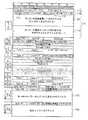
さて、次に、本実施形態のシステムにおいて使用される上記の各種メッセージについて整理すると、次表1に示すようになる。
【0054】
【表1】
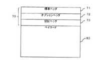
以下、これらのメッセージの詳細について説明する。なお、以下では、これらのメッセージを「モバイルメッセージ」と総称する。これらの「モバイルメッセージ」は、「MIPv6」準拠の制御メッセージを拡張したもので、基本的には、いずれも、図7に示すような「MIPv6」に準拠したパケット(以下、「MIPv6」パケットともいう)のフォーマットを有している。
【0056】
即ち、「MIPv6」パケットは、標準ヘッダ71,オプションヘッダ72及び認証ヘッダ73から成るIPヘッダ70とIPペイロード80とから成るが、「モバイルメッセージ」は、これらのうちIPペイロード80を除く部分で構成される。そして、上記のIPヘッダ70(特に、オプションヘッダ72)の設定内容によって上記の各メッセージ(パケット)が表示(識別)されるのである。
【0057】
なお、標準ヘッダ71には、図8に示すように、「バージョン情報」(4ビット),「トラフィッククラス」(8ビット),「フローラベル」(20ビット),「ペイロード長」(16ビット),「ネクストヘッダ」(8ビット),「ホップ制限数」(8ビット),「送信元アドレス(SA:Source Address)」(128ビット),「宛先アドレス(DA:Destination Address)」(128ビット)が格納される各フィールド711〜718が用意されている。
【0058】
以下、上記の各モバイルメッセージのパケットフォーマットについて説明する。
(1)ホーム位置登録/位置登録応答メッセージ
図9にホーム位置登録メッセージのパケットフォーマット(ただし、IPヘッダ70に相当する部分)を示す。この図9から分かるように、ホーム端末3のホーム網1(2)への位置登録〔VHA10(20)に対する位置登録〕には、「MIPv6」のオプションヘッダ72の宛先オプションとして定義されている結合更新(Binding Update)オプション及びホームアドレス(Home Address)オプションを使用する。次表2に結合更新オプション(位置登録)パラメータを、次表3にホームアドレスオプションパラメータをそれぞれ示す。
【0059】
【表2】
【表3】
そして、図9に示すように、ホーム位置登録メッセージの場合は、SAフィールド717に端末3のCO A(MN-COA)が格納され、DAフィールド718にVHA10(20)のアドレス(VHAアドレス)が格納される。これにより、VHA10(20)にホーム位置登録メッセージが到着し、「SAフィールド」に格納されているCOAが「キャッシュ情報」に登録されて端末3の位置登録(更新)が行なわれることになる。なお、本メッセージが「結合更新メッセージ」であることは、オプションタイプ(Option Type)フィールド723に表示(ここでは、“198”)される。
【0062】
これに対し、上記のホーム位置登録メッセージを受けたVHA10(20)から端末3へのホーム位置登録応答には、図10に示すパケットフォーマットを用いる。即ち、ホーム位置登録応答には、「MIPv6」の宛先オプションとして定義されている結合応答(Binding Acknowledgement)オプションを使用する。次表4にこの場合の結合応答オプションパラメータを示す。
【0063】
【表4】
そして、図10に示すように、ホーム位置登録応答メッセージの場合は、SAフィールド717に発信ノード〔この場合はVHA10(20)〕のアドレスが格納され、DAフィールド718にMN-COA〔受信パケット(つまり、上記のホーム位置登録メッセージ)のSA〕が格納されることにより、VHA10(20)位置登録を行なった端末3宛に本メッセージが発行(返信)されて、位置登録完了の旨が通知されることになる。
【0065】
なお、ホーム位置登録メッセージを受けたVHA11(21)が位置登録応答メッセージを発行すべきか否かは結合更新オプションのA(Acknowledgement)ビットフィールド727に表示される(表2に示すように、“1”で要を表す)。また、図9及び図10において、IPヘッダ長やヘッダ拡張長等のLengthフィールドの取り扱いは、次表5のとおりである。
【0066】
【表5】
(2)在圏位置登録/位置登録応答メッセージ
次に、在圏網1a,1b(2a,2b)への位置登録〔THA11(21)に対する位置登録〕には、図11に示すパケットフォーマットを使用する。即ち、「HMIPv6」の宛先オプション72として定義されている結合更新(Binding Update)オプションと同等の登録オプション(Registration)及びホームアドレスオプション(表3参照)を使用する。次表6に登録オプションパラメータを示し、次表7,8にそれぞれ表6中に示す前MAアドレスサブオプション(previous mobility agent address sub-option)パラメータ,ホームエージェントアドレスサブオプション(home agent address Sub-Option)パラメータを示す。
【0068】
【表6】
【表7】
【表8】
そして、図11に示すように、本在圏位置登録(Registration)メッセージの場合も、基本的に、上述したホーム位置登録メッセージと同様に、SAフィールド717に端末3のCOA(MN-COA)が格納され、DAフィールド718にTHA11(21)のアドレス(THAアドレス)が格納されることにより、THA11(21)に本在圏位置登録メッセージが到着し、SAフィールド717に格納されているCOAがTHA11(21)の「キャッシュ情報」に登録されて端末3の位置登録(更新)が行なわれることになる。
【0072】
なお、本メッセージが「Registration」メッセージであることは、オプションタイプフィールド723に表示(ここでは、“9”)される。また、前MAアドレスサブオプションの前MAアドレスフィールド721には、端末3が移動する前に位置登録を行なっていたTHA11(21)のアドレスが格納され、THA11(21)は、この前MAアドレスフィールド721に設定されているアドレスを参照することで、在圏端末3がどのTHA11(21)の在圏ゾーンから移動してきたかを認識できることになる。
【0073】
なお、図11においても、IPヘッダ長やヘッダ拡張長等のLengthフィールドの取り扱いは、前記の表5のとおりである。
これに対し、THA11(21)から端末3への位置登録応答には、前記の結合応答オプション(表4参照)を使用する。つまり、図10に示すものと同様のパケットフォーマットを使用する。そして、SAフィールド717に発信ノード〔この場合は、THA11(21)〕のアドレスが格納され、DAフィールド718にMN-COA(受信パケットのSAフィールド717に設定されていたアドレス)が格納されることにより、THA11(21)に対して位置登録を行なった端末3宛に本メッセージが発行(返信)されて、位置登録完了の旨が通知されることになる。
【0074】
(3)位置(キャッシュ)更新/応答メッセージ
次に、VHA10(20)又はTHA11(21)からEN12への位置更新(キャッシュ更新)には、図12に示すパケットフォーマット(IPヘッダ70に相当する部分)を使用する。即ち、結合更新オプション及びホームアドレスオプション(前記の表3参照)を使用する。ただし、更新対象の端末3のCOAは、結合更新オプションの代替COAサブオプション(Alternate Care of Address Sub-Option)によって通知する。次表9に結合更新オプション(位置更新)パラメータ例を、次表10に代替COAサブオプションパラメータ例を示す。
【0075】
【表9】
【表10】
なお、本位置更新メッセージは、上述した端末3からVHA10(20)又はTHA11(21)への位置登録によりVHA10(20)又はTHA11(21)の「キャッシュ情報」が更新されることに伴って通信中のEN12にその更新を反映させる必要があるときに発行されるメッセージである。
このため、図12に示すように、本位置更新メッセージの場合は、SAフィールド717にVHA10(20)又はTHA11(21)のアドレスが格納されるとともに、DAフィールド718にEN12のアドレス(通信中ENアドレス)が格納され、且つ、代替COAフィールド722に位置更新対象の端末3のCOA(MN-COA)が格納される。
【0078】
これにより、「キャッシュ情報」の更新が必要な通信中EN12に更新情報(MN-COA)が提供されて、通信中EN12の「キャッシュ情報」が更新され、通信中EN12は、端末3に対するパケットルーティングを正常に継続することが可能になる。なお、本メッセージが「位置更新メッセージ」であることは、代替COAフィールド722の有無によって識別できる。
【0079】
一方、通信中EN12は、上記の位置更新メッセージに対する応答(位置更新応答メッセージ)を発行元のVHA10(20)又はTHA11(21)に返信するが、このときの位置更新応答には、図13に示すパケットフォーマット(IPヘッダ70に相当する部分)を使用する。即ち、本メッセージの場合も、結合応答オプション(パラメータについては前記の表4参照)を使用する。
【0080】
そして、この図13に示すように、本位置更新応答メッセージの場合は、SAフィールド717に発信ノード(EN12)のアドレスが格納され、DAフィールド718に上記の受信パケット(位置更新メッセージ)のSAフィールド717に設定されていたアドレス〔つまり、位置更新メッセージの発信元のVHA10(20)又はTHA11(21)のアドレス〕が格納されることにより、そのVHA10(20)又はTHA11(21)宛に本メッセージが発行(返信)されて、位置更新完了の旨が通知されることになる。
【0081】
なお、この場合も、本位置更新メッセージを受けたEN12がそれに対する応答メッセージを発行すべきか否かは結合更新オプションのA(Acknowledgement)ビット(表2参照)に表示される(“1”で要を表す)。また、図12及び図13においても、IPヘッダ長やヘッダ拡張長等のLengthフィールドの取り扱いは、前記の表5に準ずる。
【0082】
(4)キャッシュ要求/通知メッセージ
次に、EN12からVHA10(20)又はTHA11(21)へのキャッシュ要求(後述するキャッシュ検索によりキャッシュヒットしなかった場合に発行される)には、また、図14に示すパケットフォーマット(IPヘッダ70に相当する部分)を使用する。即ち、「MIPv6」の宛先オプションとして新規に定義した結合要求〔Binding Reauest for M3 (BR-M3)〕オプションを使用する。
【0083】
なお、このキャッシュ要求は、EN12がVHA10(20)又はTHA11(21)のアドレスを既知である場合には、VHA10(20)又はTHA11(21)をDAとして本メッセージを発行する。このとき、どのアドレスに対する「キャッシュ」を要求しているかを示すためにホームアドレスオプションを使用する。
【0084】
また、別の例として、DAに「キャッシュ」を要求したいアドレスを直接指定する方法もある。この場合、「キャッシュ」をもっているエージェント〔VHA10(20)/THA11(21)〕は、BR-M3メッセージであることを宛先オプションから判断し、DAから「キャッシュ」を要求するアドレスを知るように定義することも可能である。
【0085】
次表11にBR-M3オプションパラメータ例を、次表12に表11中に示す固有IDサブオプション(Unique Identifier Sub-Option)パラメータ例を、次表13にホームアドレスオプション(キャッシュ要求)パラメータ例をそれぞれ示す。
【0086】
【表11】
【表12】
【表13】
そして、図14に示すように、本キャッシュ要求メッセージの場合は、BR-M3オプションのオプションタイプフィールド723に、本メッセージがBR-M3メッセージであることを表す値(例えば、“16”)が格納され、SAフィールド717にEN12のアドレスが格納され、DAフィールド718にキャッシュを知りたい端末3のアドレス、又は、その端末3に対応するエージェント〔VHA10(20)又はTHA11(21)〕のアドレスが格納される。また、DAフィールド718に後者のアドレスを格納する場合には、ホームアドレスフィールド724に、キャッシュを要求したいノードのホームアドレスが格納される。
【0090】
これに対し、EN12へのキャッシュ通知には、図15に示すパケットフォーマットを使用する。即ち、結合更新オプション及びホームアドレスオプションを使用する。次表14に、この場合の結合更新(Binding Update)オプションパラメータ例を、次表15及び次表16に表14中に示す固有IDサブオプション(Unique Identifier Sub-Option)パラメータ例及び代替COAサブオプション(Alternate Care of Address Sub-Option)パラメータ例を示す。なお、代替COAサブオプションは、キャッシュエントリを特定するために使用される。また、ホームアドレスオプションパラメータは前記の表3と同様である。
【0091】
【表14】
【表15】
【表16】
そして、図15に示すように、キャッシュ通知の場合は、SAフィールド717に上記のキャッシュ要求を受けたVHA10(20)又はTHA11(21)のアドレスが格納され、DAフィールド718にキャッシュ通知対象の通信中EN12のアドレスが格納される。また、代替COAサブオプションの代替COAフィールド722には端末3のCOAが格納される。
【0095】
これにより、本キャッシュ通知は、目的の通信中EN12に到着し、そのEN12では、代替COAに格納されている端末3のCOAを自己のキャッシュとして保持することになる。なお、本メッセージが、「キャッシュ通知メッセージ」であることは、結合更新オプションにより識別でき、代替COAサブオプションを使用していれば(オプションタイプフィールド723aが代替COAの存在を表示していれば)、SA以外をCOAとして使うことが分かる。従って、「キャッシュ」を作る際、検索キーについてはホームアドレスオプションフィールド724に設定された値を用い、COAについては代替COAフィールド722に設定された値(MN-COA)を用いることになる。
【0096】
(5)キャッシュ削除要求/応答メッセージ
次に、EN12からVHA10(20)又はTHA11(21)へのキャッシュ削除要求には、図16に示すパケットフォーマットを使用する。即ち、前記の結合更新オプションを使用する。また、キャッシュ削除対象の端末3のアドレスを通知するためにホームアドレスオプション(そのパラメータについては前記の表3参照)を使用する。次表17にこの場合の結合更新オプション(キャッシュ削除要求)パラメータ例を示す。
【0097】
【表17】
そして、図16に示すように、本キャッシュ削除要求メッセージの場合は、SAフィールド717にEN12のアドレスが格納され、DAフィールド718にVHA10(20)又はTHA11(21)のアドレスが格納される。また、ホームアドレスフィールド724に、EN12においてキャッシュを削除した端末3のホームアドレス(VHA10(20)又はTHA11(21)での削除対象キャッシュを特定する検索キーとして用いられる)が格納される。
【0099】
なお、本メッセージが「キャッシュ削除要求メッセージ」であることは、上記の表17及びこの図16に示すように、リザーブ(reserved)ビットフィールド728に“1(0x01)”、ライフタイム(Lifetime)フィールド729に“0”が設定されることによって表示される。
これにより、通信中EN12が非通信中となり、該当キャッシュが削除されることに伴って、その削除したキャッシュの通知元であるVHA10(20)又はTHA11(21)に対して本キャッシュ削除要求メッセージが発行され、そのVHA10(20)又はTHA11(21)において、もはや保持しておく必要の無い情報が適切に削除されることになる。
【0100】
なお、本キャッシュ削除要求メッセージを受けたVHA10(20)又はTHA11(21)は、キャッシュ削除要求応答メッセージをEN12に対して返信するが、このキャッシュ削除要求応答メッセージには、前記の結合応答オプション(パラメータについては前記の表4参照)を使用する。即ち、本メッセージには、図10に示すものと同様のパケットフォーマットを使用する。
【0101】
そして、SAフィールド717に受信パケット(キャッシュ削除要求メッセージ)のDAフィールド718に設定されていたアドレス〔つまり、VHA10(20)又はTHA11(21)のアドレス〕が格納され、DAフィールド718に受信パケットのSAフィールド717に設定されていたアドレス(つまり、キャッシュ削除要求を発行した通信中EN12のアドレス)が格納されることにより、通信中EN12に対してキャッシュ削除を行なった旨が返信されて通知されることになる。
【0102】
(A3)システムの構成要素の詳細説明
次に、以下では、上記のVHA10(20),THA11(21),EN12及び端末(MN)3を実現するためのそれぞれの構成について詳述する。なお、以下では、説明の便宜上、VHA10(20),THA11(21),EN12及びMN3は、それぞれ、単にVHA,THA,EN,MNと符号を略して表記する場合がある。また、これらを特に区別しない場合には、単に「ノード」と総称する場合もある。
【0103】
(A3.1)VHA,THA,ENの詳細説明
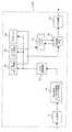
図2は上記のVHA10(20),THA11(21)及びEN12の要部の詳細構成を示すブロック図で、この図2に示すように、本実施形態において、VHA10(20),THA11(21)及びEN12は、それぞれ、共通の構成を有しており、例えば、入力処理部41,パケット種別識別部42,バインディングキャッシュ検索部43,結合(バインディング)キャッシュ(Binding Cache)テーブル44,カプセル化処理部45,ルータ処理部46(ルーティングテーブル46a,出方路決定部46b),出力処理部48,タイマ処理部49及び制御メッセージ処理部50をそなえて構成されている。なお、この図2において、符号431はトラフィック種別識別部を表し、符号434はブリッジ部を表すが、これらの各部の機能についてはそれぞれ第2実施形態にて後述する。
【0104】
ここで、入力処理部41は、到着(受信)パケットのIPレイヤ以下の処理を行なうためのもので、例えば、イーサネットであれば自ノード宛のMAC(Media Access Control)アドレスが付与されたパケットを取り込んで、そのパケットのフレーム自体の正常性をチェックする処理を行なう機能を装備するものである。
【0105】
また、パケット種別識別部42は、この入力処理部41で受信された正常なパケットの種別〔主に、制御メッセージ,マルチキャストパケット,これら以外のパケット等〕を、そのヘッダ部分(具体的には、DAフィールド718)を参照して識別するためのもので、ここでは、上述した各種制御メッセージやマルチキャストパケットは制御メッセージ処理部50へ、それ以外のパケットはバインディングキャッシュ検索部43へそれぞれ引き渡されるようになっている。
【0106】
次に、図2に示す結合キャッシュテーブル(以下、単に「キャッシュテーブル」ともいう)44は、基本的に、「MIPv6」ベースで作成される「キャッシュ」を端末3のホームアドレス(MNホームアドレス)別にテーブル形式のデータとして保持するもので、例えば、RAMやレジスタ等の所要の記憶デバイスによって構成される。ただし、このキャッシュテーブル44は、VHA/THAにおけるものと、ENにおけるものとで保持内容が若干異なる。
【0107】
即ち、VHA/THAのキャッシュテーブル44には、例えば図4(A)に示すように、“COA”(128ビット),“Lifetime”(32ビット),“Home registration flag”(1ビット),“router flag”(1ビット),“prefix length”(7ビット),“Sequence Number”(16ビット),“Rec ent Usage Information”(1ビット),“last BR time”(128ビット)等のキャッシュデータ61aとともに、ここでは、複数(本例では、最大16台分)の「通信中ENアドレス」(128ビット×16)データ(拡張データ)61bが保持される。
【0108】
これは、1台の端末3に対して、複数(最大16台)のENへ「キャッシュ」をコピーできることを意味する。つまり、VHA/THAに代わってルーティングを行なえるENを複数台設定することができ、VHA/THAの処理負荷をENに分散して大幅に削減することができることを意味する。
さて、これに対し、EN12のキャッシュテーブル44には、図4(B)に示すように、VHA又はTHAから通知される上記のキャッシュデータ61aとともに、「VHA/THAアドレス」(128ビット)データ(拡張データ)62bが保持される。なお、後述するように、上記のキャッシュテーブル44は、モバイルメッセージ処理部52によって作成(登録)され、そのエントリのうち“Lifetime”の更新(減算)がタイマ処理部49によって行なわれるようになっている。
【0109】
つまり、VHA/THAにおけるキャッシュテーブル44,タイマ処理部49及びモバイルメッセージ処理部52から成る部分は、端末3(後述する現在位置登録手段)によって通知され登録されるCOA(現在位置情報)を管理する端末位置管理手段としての機能を果たしていることになり、VHA/THAのキャッシュテーブル44は、通信中EN12のENアドレス(識別情報)を保持するノード識別情報保持手段としての機能も果たすことになる。
【0110】
これに対し、EN側のキャッシュテーブル44は、後述するキャッシュ情報通知手段として機能するVHA/THA/他ENの結合更新メッセージ作成部524(図3にて後述)によって作成・発行されるキャッシュ通知メッセージにより通知される「キャッシュ」を保持するキャッシュ手段としての機能を果たすことになる。
【0111】
そして、バインディングキャッシュ検索部(以下、単に「キャッシュ検索部」ともいう)43は、入力パケットのIPヘッダ70に含まれるMN3のホームアドレス(128ビット)を検索キーとして、上記のキャッシュテーブル44(データ61a又は62a)を検索して現在のMN3の位置情報(COA)等を取得するためのものである。
【0112】
また、カプセル化処理部45は、このキャッシュ検索部43のキャッシュ検索により得られたCOA等の情報に基づいて受信パケットをカプセル化するものであり、ルータ処理部46において、出方路決定部46bは、カプセル化されたパケット(これをトンネルパケットという)に付加されたCOAを検索キーとしてルーティングテーブル46aに保持されているルーティング情報を検索して、そのCOAに応じた出方路(出力インタフェース)や下位レイヤでの宛先アドレス等を決定するものである。
【0113】
つまり、このルータ処理部46は、ENにおいては、キャッシュ手段としての上記キャッシュテーブル44に保持されているキャッシュ情報(以下、キャッシュエントリともいう)に基づきVHA/THA(ゲートノード)に代わって端末3宛のパケットの在圏ENへのルーティングを実施するルーティング手段として機能するのである。
【0114】
さらに、出力処理部48は、決定した出力ポートへ受信パケットを出力して次ホップ先へ転送するもので、例えば、イーサネットの場合にはイーサネットフレームに必要なフレームチェックシーケンス符号を付けて、パケット(フレーム)送出を行なうようになっている。これにより、受信パケットはVHA10(20)から所望のTHA11(21)(「VCOA」の場合)まで、あるいは、THA11(21)から所望のEN12まで(「PCOA」の場合)正しく転送されることになる。
【0115】
さらに、タイマ処理部49は、上述したキャッシュテーブル44における「キャッシュ」のうちデータ61aに含まれる“Lifetime”を前述したように更新する機能、即ち、入力処理部41でパケットが受信されない間は“Lifetime”をデクリメントし、パケットが受信されている間は“Lifetime”が切れない(“0”にならない)ように更新する機能を有するとともに、“Lifetime”が切れたときに、該当「キャッシュ情報」を削除する機能を有するものである。
【0116】
次に、制御メッセージ処理部50は、パケット種別識別部42で制御メッセージであると識別されて入力される制御メッセージに応じた処理を実施するためのもので、本実施形態では、例えば図2中に示すように、メッセージ種別判定部51,モバイルメッセージ処理部52,ルーティングメッセージ処理部53及びルータ広告(RA:Router Advertise)メッセージ処理部54をそなえて構成されている。ただし、このルータ広告メッセージ処理部54は、EN12に固有の機能で、VHA10(20)やTHA11(21)には実装されていなくてもよい。
【0117】
ここで、上記のメッセージ種別判定部51は、受信制御メッセージの種別を判定(識別)するためのもので、ここでは、上述したモバイルメッセージとそれ以外のルーティングメッセージとを判別して、モバイルメッセージについてはモバイルメッセージ処理部52へ、ルーティングメッセージについてはルーティングメッセージ処理部53へ振り分けられるようになっている。
【0118】
また、モバイルメッセージ処理部52は、受信したモバイルメッセージの種別を判定してその種別に応じた処理を実施するためのもので、本実施形態では、そのメッセージ種別として、前述したように、主に、▲1▼結合更新(Binding Update)オプションを使用した結合更新メッセージ(ホーム/在圏位置登録メッセージ,キャッシュ更新メッセージ,キャッシュ削除要求メッセージ),▲2▼結合応答(Binding Ack)オプションを使用した結合応答メッセージ(ホーム/在圏位置登録応答メッセージ,キャッシュ通知メッセージ,キャッシュ削除応答メッセージ,キャッシュ更新応答メッセージ),▲3▼結合要求(Binding Request-M3)メッセージがある。
【0119】
このため、本モバイルメッセージ処理部52は、例えば図3に示すように、結合更新(Binding Update)メッセージ処理部52C,結合応答(Binding Acknowledge)メッセージ処理部52D及び結合要求(Binding Request-M3)メッセージ処理部52Eを有して構成されている。
ここで、上記の結合更新メッセージ処理部52Cは、上記のメッセージ種別判定部51から入力される結合更新メッセージに応じた処理を行なうためのもので、本実施形態では、例えば、結合キャッシュ(Binding Cache)テーブルアクセス部521,結合更新(Binding Update)メッセージ解析部522,結合応答(Binding Acknowledge)メッセージ作成部523,結合更新(Binding Update)メッセージ作成部524をそなえている。ただし、結合更新メッセージ作成部524の機能は、VHA10(20)又はTHA11(21)にのみ実装され、EN12には無い。
【0120】
ここで、上記の結合キャッシュテーブルアクセス部521(以下、単に「テーブルアクセス部521」と表記する)は、上述したキャッシュテーブル44に対してMNホームアドレスを検索キーとしてアクセスしその保持内容(キャッシュ)を更新・削除することができるものであり、結合更新メッセージ解析部522は、メッセージ種別判定部51から入力される結合更新メッセージの内容を解析するためのものである。
【0121】
そして、VHA/THAの場合は、この結合更新メッセージ解析部522での解析結果により、受信した結合更新メッセージが端末3からのホーム/在圏位置登録メッセージであれば、テーブルアクセス部521によって、そのメッセージによって通知されるCOAが、同じメッセージに設定されているMNホームアドレスで特定されるキャッシュテーブル44の記憶領域(メモリアドレス)に書き込まれて位置登録が行なわれ、それに伴って、結合更新メッセージ作成部524によって、通信中EN12に対するキャッシュ更新メッセージが作成・発行されることになる。
【0122】
つまり、この結合更新メッセージ作成部524は、端末3の移動に伴って現在位置通知手段として機能する位置登録メッセージ作成部343(図6にて後述)により端末3から新たに通知されてくる現在位置情報(COA)に基づいて、通信中EN12の「キャッシュ」を更新するキャッシュ情報更新手段としての機能を果たすのである。これにより、通信中EN12のルータ処理部46は、更新後の「キャッシュ」に基づいて端末3宛のパケットをTHA/VHAに代わって新たな移動先(在圏EN12)へ正しくルーティングすることが可能となる。
【0123】
また、受信した結合更新メッセージが通信中EN12からのキャッシュ削除要求メッセージであれば、テーブルアクセス部521によって、そのメッセージに設定されているMNホームアドレスを検索キーとして、該当「キャッシュ」(「通信中ENアドレス」データ61b)が削除されるとともに、結合応答メッセージ作成部523によって、上記通信中EN12宛のキャッシュ削除応答メッセージが作成・発行されることになる。
【0124】
つまり、テーブルアクセス部521は、EN12の結合更新メッセージ作成部527によって作成・発行されたキャッシュ削除要求メッセージを受けると、自ノード(VHA/THA)のキャッシュテーブル44に保持している「通信中ENアドレス」データ62bを削除するノード識別情報削除手段としての機能を果たすのである。
【0125】
これに対し、EN12の場合は、上記の結合更新メッセージ解析部522での解析結果により、受信した結合更新メッセージがVHA10(20)又はTHA11(21)からのキャッシュ更新メッセージであれば、テーブルアクセス部521によって、そのメッセージによって通知されるCOAが、同じメッセージに設定されているMNホームアドレスで特定されるキャッシュテーブル44の記憶領域に書き込まれて、VHA/THAで管理されているキャッシュとの同期がとられ、それに伴って、結合応答メッセージ作成部523によって、VHA/THA宛のキャッシュ更新応答メッセージが作成・発行されることになる。
【0126】
さて、次に、図3に示す結合応答メッセージ処理部52Dは、メッセージ種別判定部51から入力される結合応答メッセージについての受信処理を行なうもので、そのメッセージ内容を解析して必要に応じて内部パラメータの変更等を行なうようになっている。
また、結合要求メッセージ処理部52Eは、メッセージ種別判定部51から入力される結合要求メッセージに応じた処理を行なうためのもので、このために、本実施形態では、結合キャッシュ(Binding Cache)テーブルアクセス部525,結合要求(Binding Request-M3)メッセージ解析部526,結合更新(Binding Update)メッセージ作成部527及び結合要求(Binding Request-M3)メッセージ作成部528をさらにそなえている。
【0127】
ここで、結合キャッシュテーブルアクセス部525(以下、単に「テーブルアクセス部525」と表記する)は、結合更新メッセージ処理部52Cにおけるものと同様に、キャッシュテーブル44に対してMNホームアドレスを検索キーとしてアクセスしその保持内容(キャッシュ)を更新することができるものであり、結合要求メッセージ解析部526は、メッセージ種別判定部51から入力される結合要求メッセージ〔キャッシュ要求(BR-M3)メッセージ〕の内容を解析するためのものである。
【0128】
そして、この結合要求メッセージ解析部526での解析結果により、そのメッセージに設定されているMNホームアドレスを検索キーとして、テーブルアクセス部525が、キャッシュテーブル44を検索して、該当キャッシュを取得し、これに伴って、結合応答メッセージ作成部527が、そのキャッシュを要求元のノード(VHA/THA/EN)に通知するキャッシュ通知メッセージを作成・発行することになる。
【0129】
つまり、この結合応答メッセージ作成部527は、端末3宛のパケットを自己宛にルーティングしてくるEN(通信中EN)12からキャッシュ要求(BR-M3)メッセージを受けた場合に、キャッシュテーブル44で管理(保持)されているキャッシュ(COA等)をその通信中EN12に通知するキャッシュ情報通知手段としての機能を果たすのである。
【0130】
なお、この結合更新メッセージ作成部527は、EN12においては、前述したタイマ処理部49(図2参照)によって“Lifetime”の切れた「キャッシュ」が削除された場合に、キャッシュ通知を発行したVHA/THA/ENに対して該当する「キャッシュ」(「通信中ENアドレス」データ62b)の削除を要求するキャッシュ削除要求メッセージを発行する機能も有する。
【0131】
つまり、この結合更新メッセージ作成部527は、EN12の通信が終了して「キャッシュ」の有効期限が切れると、その「キャッシュ」の「通信中ENアドレス」データ62bの削除をキャッシュ通知元のノード(VHA/THA/EN)に要求するノード識別情報削除要求手段としての機能を果たすのである。
また、結合要求メッセージ作成部(キャッシュ情報要求手段)528は、前記のキャッシュ検索部43による検索の結果、必要な「キャッシュ」がキャッシュテーブル44に保持されていないことが分かった場合に、VHA/THA/他EN宛の結合要求メッセージ(キャッシュ要求メッセージ)を作成・発行するものである。
【0132】
そして、メッセージ送信部52Fは、上記の結合応答メッセージ作成部523,結合更新メッセージ作成部524,527及び結合要求メッセージ作成部527で作成された各種メッセージをルータ処理部46(出力方路決定部46b;図2参照)へ送信するもので、これにより、各種メッセージがそれぞれ所望の出力インタフェースを通じて次ホップ先ノードへ転送されることになる。
【0133】
さて、次に、図2において、ルーティングメッセージ処理部53は、メッセージ種別判定部51からモバイルメッセージ以外の制御メッセージであると判定されて入力されてくるRIP(Routing Information Protocol)等のルーティングメッセージについての処理(例えば、網構成の変更等に伴うルーティング情報の更新等)を実施するためのものであり、EN12に固有のルータ広告メッセージ処理部54は、在圏端末3に対するルータ広告を発行するためのものであるが、本実施形態では、前述したように、ENアドレスと、THAアドレスと、M3ネットワークアドレスとを含む「ルータ広告」が作成・発行されるようになっている。
【0134】
即ち、本ルータ広告メッセージ処理部54は、例えば図17に示すように、SAフィールド717にENアドレス(ルータ広告送信ノードのリンクローカルアドレス)、モビリティオプション(Type:100)として定義されるMAアドレスフィールド725にTHAアドレス〔ローカルリンクにある(換言すると、EN12が収容されている)THA11(21)のアドレス〕、モビリティオプション(Type:101)として定義されるM3ネットワークアドレスフィールド726にM3ネットワークアドレスをそれぞれ格納した「ルータ広告」を作成・発行するようになっている。
【0135】
なお、「リンクローカルアドレス」とは、ルータ広告送信ノード配下のリンクでしか使えないアドレスを意味し、「ルータ広告」以外の用途にも使用される。
(A3.2)端末(MN)3の詳細構成説明
次に、以下では、端末3の詳細構成について説明する。
図5は上記の端末3の詳細構成を示すブロック図で、この図5に示すように、本実施形態の端末3は、入力処理部31,IPレイヤ処理部32,パケット種別判定部33,モバイルメッセージ処理部34,ルーティングメッセージ処理部35,アプリケーション36,ルーティングテーブル37,出力方路決定部38及び出力処理部39をそなえて構成されている。
【0136】
ここで、上記の入力処理部31は、最寄りの(ローカルリンクの)EN12からパケットを受信するものであり、IPレイヤ処理部32は、この入力処理部31から入力されるパケットについてデカプセル処理(ただし、パケットがカプセル化されている場合のみ)やルーティングヘッダ処理などの各種IPレイヤ処理を施すためのものである。
【0137】
また、パケット種別判定部33は、上記IPレイヤ処理後の受信パケットの種別(モバイルメッセージ,ルーティングメッセージ等)を判定するもので、モバイルメッセージ(この場合は、主に「ルータ広告」やホーム/在圏位置登録応答メッセージ等)はモバイルメッセージ処理部34へ、ルーティングメッセージはルーティングメッセージ処理部35へ、これら以外のパケット(ユーザパケット等)はアプリケーション部36へそれぞれ振り分けられるようになっている。
【0138】
さらに、ルーティングメッセージ処理部35は、モバイルメッセージ以外の制御メッセージ(ルーティングメッセージ)を処理するためのものであり、アプリケーション部36は、制御メッセージ以外のパケット(ユーザパケット等)についての受信処理を担うものであり、モバイルメッセージ処理部34は、EN12から報知されている「ルータ広告」の受信に伴う位置登録処理やホーム/在圏位置登録応答メッセージ等についての処理を担うものである。
【0139】
このため、本モバイルメッセージ処理部34は、その要部に着目すると、例えば図6に示すように、メッセージ受信部34A,メッセージ種別判断部34B,ルータ広告メッセージ処理部34C,モバイルIPメッセージ処理部34D及びメッセージ送信部34Eをそなえており、ルータ広告メッセージ処理部34Cは、さらに、情報格納レジスタ341,ルータ広告解析部342,位置登録(Registration)メッセージ作成部343及び結合更新(Binding Update)メッセージ作成部344をそなえて構成されている。
【0140】
ここで、上記のメッセージ受信部34Aは、パケット種別判定部33から振り分けられてくるモバイルメッセージを受信するものであり、メッセージ種別判断部34Bは、受信モバイルメッセージが、「ルータ広告」及びそれ以外のモバイルIPメッセージのいずれであるかを判断するもので、この場合、「ルータ広告」はルータ広告メッセージ処理部34Cへ、それ以外のモバイルIPメッセージはモバイルIPメッセージ処理部34Dへそれぞれ転送されるようになっている。
【0141】
そして、ルータ広告メッセージ処理部34Cにおいて、情報格納レジスタ341は、受信「ルータ広告」に含まれる前記のENアドレス,THAアドレス及びM3ネットワークアドレス(以下、「アドレス情報」と総称することがある)を保持するためのものであり、ルータ広告解析部342は、上記のメッセージ種別判断部34Bから転送されてくる「ルータ広告」の内容を解析するもので、このルータ広告解析部342において、上記のENアドレス,THAアドレス及びM3ネットワークアドレスが抽出されて、上記情報格納レジスタ34に格納されるようになっている。
【0142】
ただし、このルータ広告解析部342は、情報格納レジスタ34に保持されている過去のアドレス情報と、最新の受信「ルータ広告」に含まれるアドレス情報とを比較する機能も有しており、本実施形態では、その比較により、端末3の移動に伴ってENアドレスが変化していてもM3ネットワークアドレスが変化していなければTHAアドレスを更新しないようになっている。
【0143】
これにより、「HMIPv6」では、位置登録メッセージ作成部343が、ENアドレスの変化を契機に、新しいTHAアドレスをもつTHA11(21)宛に在圏位置登録メッセージを作成・発行するのだが、M3ネットワークアドレスに変化が無い限り、位置登録メッセージ作成部343は、元のTHAアドレスをもつTHA11(21)宛の在圏位置登録メッセージを作成・発行することになる。
【0144】
つまり、上記のメッセージ受信部34Aは、在圏EN12から報知される「ルータ広告」(報知情報)を受信する報知情報受信手段としての機能を果たし、ルータ広告解析部342は、このメッセージ受信部34Aで受信された「ルータ広告」に含まれるTHAアドレス(ゲートノード識別情報)が変化したか否かを監視するゲートノード識別情報監視手段と、「ルータ広告」に含まれるM3ネットワークアドレス(網識別情報)が変化したか否かを監視する網識別情報監視手段としての機能を果たし、さらに、上記の位置登録メッセージ作成部343は、上記のゲートノード識別情報監視手段でTHAアドレスの変化が検知されても網識別情報監視手段でM3ネットワークアドレスの変化が検知されていなければ、同じTHAに自己の現在位置情報(COA)を通知する現在位置通知手段としての機能を果たすのである。
【0145】
そして、これらの各手段をそなえることにより、本実施形態のモバイルメッセージ処理部34は、在圏EN12のENアドレスに基づくCOA(「PCOA」)をVHA/THAに通知して登録する現在位置登録手段としての機能を有していることになる。
ただし、上記の処理は端末3がローミング中の場合であって、非ローミング中(つまり、ホーム網1(2)を移動している場合)には、ENアドレスの変化が検出される毎に、結合更新メッセージ作成部344によって、VHA10(20)宛のホーム位置登録メッセージが作成・発行され、VHA10(20)に対して位置登録(「PCOA」の登録)が行なわれる。つまり、端末3がホーム網1(2)に存在する場合は、THA11(21)は使用されないようになっているのである。
【0146】
このときの端末3がホーム網3内に位置しているか否かの判断は、ホーム網3のM3ネットワークアドレスをデフォルトアドレス(これを「M3ホームネットワークアドレス」という)として情報格納レジスタ341に予め格納しておき、「ルータ広告」に含まれるM3ネットワークアドレスとの比較により行なうようにすればよい。なお、「ルータ広告」にM3ネットワークアドレスが含まれていない場合は、その網が非「M3対応網」である(つまり、THAが用意されていない)ことを意味する。
【0147】
この場合、端末3は、既存の「MIPv6」準拠の位置登録処理を行なうことになる。即ち、ローミング先の網が非階層化網であれば、端末3は、その移動に伴って「ルータ広告」に含まれるENアドレスが変化する度に、自己のホーム網1(2)のVHAに対して位置登録を行ない、階層化網であれば、ENアドレスが変化する度に、ローカルリンクのMAに対して位置登録を行なうことになる。なお、この場合のVHAあるいはMAに対する位置登録メッセージの作成機能は、位置登録メッセージ作成部343及び結合更新メッセージ作成部344が兼用してもよいし、専用のものを別個に用意してもよい。
【0148】
さて次に、図6に示すモバイルIPメッセージ処理部34Dは、上述した「ルータ広告」以外のメッセージ(Binding RequestやBinding Ackメッセージ等)についての処理を担うもので、例えば、上記のホーム/在圏位置登録メッセージに対する応答(ホーム/在圏位置登録応答メッセージ)等の受信処理が行なわれるようになっている。そして、メッセージ送信部34Eは、上記のホーム/在圏位置登録メッセージ等を図5に示す出力方路決定部38へ送信するものである。なお、これらは、モバイルIP端末には標準で備わる機能である。
【0149】
次に、図5において、ルーティングテーブル37は、端末3がパケットを送信する上で必要なルーティング情報を保持するためのもので、このルーティング情報は、上記のルーティングメッセージ処理部35での受信ルーティングメッセージに応じて適宜更新されるようになっている。なお、このルーティングテーブル37も、例えば、RAMやレジスタ等の所要の記憶デバイスによって実現される。
【0150】
また、出力方路決定部38は、上述したモバイルメッセージ処理部34,ルーティング処理部35及びアプリケーション部36から入力されるパケットの出力先(インタフェース)を、その宛先情報(DA)とルーティングテーブル27のルーティング情報とに基づいて決定するものであり、出力処理部39は、この出力方路決定部38での決定に従って、パケットを所望の出力インタフェースに出力するためのものである。
【0151】
(A4)動作説明
次に、上述のごとく構成された本実施形態のパケット通信システムの動作について詳述する。
(A4.1)端末3の動作(位置登録処理)説明
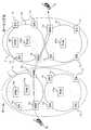
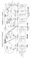
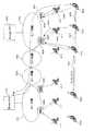
まず始めに、端末3の動作(位置登録処理)について、図18及び図22を用いて説明する。なお、図18に示すように、ここでは、説明の便宜上、「MIPv6」のアドレス表記を「“ネットワークアドレス”.“インタフェースID”」とすることにして、端末3のホーム網1のアドレス(M3ネットワークアドレス)を「100.50」、ローミング先のパケット網2のM3ネットワークアドレス)を「200.50」、THA11a,11b,21a,21bのアドレスをそれぞれ順に「10.2」,「20.2」,「30.2」,「40.2」、EN12(EN“1”〜“4”)のアドレスをそれぞれ順に「1.1」,「2.1」,「3.1」,「4.1」と仮定する。また、端末3のインタフェースIDを“3”と仮定する(従って、この場合、M3ホームネットワークアドレスは「100.3」となる)。勿論、実際のアドレス表記はこれらの表記とは異なる(例えば、「aaaa.b.c.d」等の長い表記になる)。以上の点は後述する図30においても同様である。
【0152】
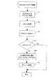
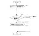
さて、図18において、まず端末3が、EN“1”の在圏ゾーン内で移動(矢印4参照)したとする。このとき、端末3では、ルータ広告解析部342(図6参照)が、図22に示すように、EN“1”から受信される「ルータ広告」のENアドレス(1.1),THAアドレス(10.2),M3ネットワークアドレス(100.50)を抽出し(ステップA1)、まず、受信したENアドレスと情報格納レジスタ341に保持されているENアドレスとを比較して、一致しているか否かを判定する(ステップA2)。
【0153】
この場合、端末3は、同一EN“1”から「ルータ広告」を受信しているので、ENアドレス(1.1)に変化は無い。従って、ルータ広告解析部341は、抽出したENアドレス(1.1),THAアドレス(10.2),M3ネットワークアドレス(100.50)をそのまま情報格納レジスタ341に格納することになる(ステップA2のYesルートからステップA5)。
【0154】
その後、さらに、端末3が移動して、異なるEN“2”の在圏ゾーン内へ移動したとする(矢印5参照)。すると、端末3では、受信した「ルータ広告」に含まれるENアドレスが「1.1」→「2.1」に変化するので、ルータ広告解析部342が、今度はその「ルータ広告」に含まれるM3ネットワークアドレスと情報格納レジスタ341に保持されているM3ホームネットワークアドレスとを比較して、それぞれが一致しているか否かをチェックする(ステップA2のNoルートからステップA3)。
【0155】
この場合、図18中に示すように、ENアドレス及びTHAアドレスは変化しているが、M3ネットワークアドレスは変化しておらず、しかも、M3ホームネットワークアドレスも変化していないので、ルータ広告解析部342は、端末3の移動がホーム網1内の移動であると認識し、結合更新メッセージ作成部344に対してホーム位置登録メッセージの作成を依頼する。
【0156】
これにより、結合更新メッセージ作成部344は、図9に示すSAフィールド717に「PCOA」を設定するとともにDAフィールド718にVHA10のアドレスを設定したホーム位置登録メッセージを作成・発行(ステップA3のYesルートからステップA4)して、VHA10に対する位置登録を実施し(図18の矢印5a参照)、「ルータ広告」により受信したENアドレス(2.1),THAアドレス(20.2),M3ネットワークアドレス(100.50)を情報格納レジスタ341に格納する(ステップA5)。
【0157】
なお、VHA10のアドレスは、端末3毎に予め設定されている。また、「PCOA」は、前述したように、EN“2”が発行する「ルータ広告」に含まれるENアドレスから作成される。即ち、ENアドレスのネットワークプレフィックス部分(本例では、「2.1」のうちの“2”の部分)と、自己のインタフェースID(=“3”)とを組み合わせて「PCOA」を作成する。従って、この場合、端末3は、「PCOA」=“2.3”を作成し、これがVHA10に通知されることになる。
【0158】
このように、本実施形態の端末3は、自己のホーム網1(2)内に位置している間は、THAには位置登録は行なわず、常に、VHAに対して「PCOA」の登録を行なう。
さて、その後、さらに端末3が移動し、図18中に矢印6で示すように、パケット網2のEN“3”の在圏ゾーンへ移動(ローミングイン)したとする。すると、この場合は、端末3で受信される「ルータ広告」に含まれるENアドレスが「2.1」→「3.1」に変化するとともに、M3ネットワークアドレスもM3ホームネットワークアドレス(100.3)と異なるアドレス(200.50)に変化するので、ルータ広告解析部342は、今度はその「ルータ広告」に含まれるM3ネットワークアドレスと情報格納レジスタ341に保持されているM3ネットワークアドレスとを比較して、それぞれが一致しているか否かをチェックする(ステップA2のNoルートからステップA3及びステップA3のNoルートからステップA6)。
【0159】
今、「ルータ広告」に含まれるM3ネットワークアドレスは元の「100.50」から「200.50」に変化しているので、ルータ広告解析部342は、端末3がパケット網1,2をまたいで移動(ローミングイン)したと認識し、位置登録メッセージ作成部343に対して在圏位置登録メッセージの作成を依頼するとともに、結合更新メッセージ作成部344に対してホーム位置登録メッセージの作成を依頼する。
【0160】
これにより、結合更新メッセージ作成部344は、図9に示すSAフィールド717に「VCOA」を設定するとともにDAフィールド718にVHA10のアドレスを設定したホーム位置登録メッセージを作成・発行して、VHA10に対する位置登録を実施する(図18の矢印6a参照)。なお、このときの「VCOA」は、THAアドレス(30.2)のネットワークプレフィックス部分(“30”)と、端末3のインタフェースID(=“3”)との組み合わせにより作成されるから、「30.3」となる。
【0161】
一方、位置登録メッセージ作成部343は、図11に示すSAフィールド717に「PCOA」(3.3)を設定するとともにDAフィールド718にTHAアドレス(30.2)を設定した在圏位置登録メッセージを作成・発行して、THA21aに対する位置登録を実施する(図18の矢印6b参照)。つまり、端末3は、パケット網1,2をまたぐ移動(ローミングイン)を行なうと、ホーム網1のVHA10とローミング先の最寄りのEN12を収容するTHA21aとのそれぞれに対して位置登録を行なうのである(以上、ステップA6のNoルートからステップA7)。
【0162】
なお、ルータ広告解析部342は、上記の各メッセージの作成依頼後、この場合も、「ルータ広告」から抽出したENアドレス(3.1),THAアドレス(30.2),M3ネットワークアドレス(200.50)をそれぞれ情報格納レジスタ341に格納(保持しているアドレス情報を更新)する(ステップA5)。
さて、次に、端末3がローミング先のパケット網2内においてさらに移動し、異なるEN“4”の在圏ゾーンに移動したとする。すると、この場合は、端末3で受信される「ルータ広告」に含まれるENアドレスが「3.1」→「4.1」に変化するが、M3ネットワークアドレスはM3ホームネットワークアドレス(100.3)と異なる「200.50」のままであるので(ステップA2及びA3でNoと判定され、且つ、ステップA6でYesと判定されるので)、ルータ広告解析部342は、位置登録メッセージ作成部343に対して在圏位置登録メッセージの作成を依頼する。
【0163】
これにより、位置登録メッセージ作成部343は、図11に示すSAフィールド717に「PCOA」(4.3)を設定するとともにDAフィールド718に情報格納レジスタ341に保持されている元のTHAアドレス(30.2)を設定した在圏位置登録メッセージを作成・発行して、同じTHA21aに対する位置登録を実施する(ステップA8;図18の矢印7a参照)。そして、ルータ広告解析部342は、「ルータ広告」により受信したENアドレス(4.1),THAアドレス(40.2),M3ネットワークアドレス(200.50)をそれぞれ情報格納レジスタ341に格納(保持しているアドレス情報を更新)する(ステップA5)。
【0164】
つまり、本実施形態の端末3は、既存の「HMIPv6」準拠のシステムであれば「ルータ広告」に含まれるENアドレスが変化しているので同じ「ルータ広告」に含まれるTHAアドレス(40.2)をもつTHA21bに対して位置登録を行なう(位置登録先のTHAを切り替える)ところであるが、ENアドレスに変化があっても、M3ネットワークアドレスに変化がないと、最初に位置登録を行なったTHA21aに対して位置登録を行ない、その移動に関わらず、同じTHA21aを位置登録先として使い続けるのである。
【0165】
これは、ローミング中に端末3がホーム網1のVHA10へ位置登録を行なうのはパケット網2へローミングインしたときだけで良いということを意味する。従って、既存の「HMIPv6」準拠のシステムのように、MAが切り替わる度にホーム網1のVHA10へ位置登録する必要がないので、端末3のローミング中のハンドオーバ時間が大幅に短縮されることになる。
【0166】
(A4.2)VHA/THAの動作説明
さて次に、以下では、VHA/THA側の動作について、図23及び図24を用いて説明する。
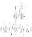
まず、図23に示すように、VHA/THAでは、パケットを受信すると、入力処理部41においてその正常性がチェックされたのち(ステップB1)、パケット種別識別部42において、DAフィールド718に設定されている宛先アドレスが抽出される(ステップB2)。そして、パケット種別識別部42は、抽出したアドレスの先頭が“0xFF”であるか否かをチェックし(ステップB3)、“0xFF”であればその受信パケットはマルチキャストパケットであるので、制御メッセージ処理部50へ転送する(ステップB3のYesルートからステップB4)。
【0167】
一方、抽出した宛先アドレスが“0xFF”以外の値であれば、パケット種別識別部42は、次に、宛先アドレスのプレフィックス部分(上位64ビット)が自VHA/THAアドレスのプレフィックス部分と一致するか否かをチェックし(ステップB3のNoルートからステップB5)、一致していなければ、その受信パケットは他ドメイン向けパケットであるので、そのままルータ処理部46aへ転送する(ステップB5のNoルートからステップB6)。
【0168】
これに対し、宛先アドレスのプレフィックス部分が自VHA/THAアドレスのプレフィックス部分と一致した場合は、パケット種別識別部42は、次に、宛先アドレス(下位64ビット)が自VHA/THAアドレスと一致するか否かをチェックし(ステップB5のYesルートからステップB7)、一致すれば、その受信パケットは自VHA/THA宛のパケット(つまり、制御メッセージ)であるので、制御メッセージ処理部50へ転送する(ステップB7のYesルートからステップB8)。
【0169】
一方、宛先アドレス(下位64ビット)が自VHA/THAアドレスと一致しない場合は、パケット種別識別部42は、次に、受信パケットの宛先オプションを参照してそのパケットがキャッシュ要求(BR-M3)メッセージ(Option Type=16)であるか否かをチェックする(ステップB7のNoルートからステップB9)。
【0170】
その結果、受信パケットがBR-M3メッセージである場合は、パケット種別識別部42は、その受信パケットを制御メッセージ処理部50へ転送し(ステップB10のYesルートからステップB11)、BR-M3メッセージでなければ、キャッシュ検索部43に受信パケットを転送する。キャッシュ検索部43は、このように転送されてきたパケットのDAフィールド718に設定されている宛先アドレスを検索キーとして、キャッシュテーブル44を検索する(ステップB10のNoルートからステップB12)。
【0171】
この検索の結果、該当宛先アドレス(COA)がキャッシュテーブル44に登録されていなければ、キャッシュ検索部43は、宛先が見つからないので、ソフトウェア(図示省略)にパケットを引き渡し、当該ソフトウェアは、例えばICMP(Internet Control Message Protocol)に従ってパケットの送信元に対して宛先が見つからない旨のエラーメッセージを発行する(ステップB13のNoルートからステップB14)。
【0172】
これに対し、受信パケットの宛先アドレスがキャッシュテーブル44に登録されていれば(キャッシュヒットすれば)、キャッシュ検索部43は、受信パケットをカプセル化処理部45に転送し、カプセル化処理部45は、キャッシュヒットしたCOAをDA,受信パケット(オリジナルパケット)のSAフィールド717に設定されていたアドレスをSAとするヘッダをオリジナルパケットに付加してカプセル化する(ステップB13のYesルートからステップB15)。
【0173】
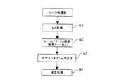
そして、カプセル化されたパケット(トンネルパケット)は、ルータ処理部46へ出力され、ルータ処理部46では、図29に示すように、出力方路決定部46bが、そのトンネルパケットのDAを抽出し(ステップG1)、そのDAを検索キーとしてルーティングテーブル46aのルーティング情報を検索する(ステップG2)ことにより、DAに応じた出力インタフェースを決定し(ステップG3)、出力処理部48へ送信する(ステップG4)。
これにより、トンネルパケットは、決定した出力インタフェースを通じてそのDAに応じた次ホップ先ノード(EN/MN)へ送信されることになる(ステップB16)。
【0174】
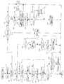
次に、制御メッセージ処理部50での処理について、図24に示すフローチャートを参照しながら詳述する。
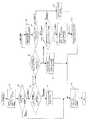
まず、制御メッセージ処理部50では、上記のステップB4やB8,B11によりパケット種別識別部42から転送されてくる制御メッセージの種別をメッセージ種別判定部51にて判定する。即ち、メッセージ種別判定部51は、受信した制御メッセージのメッセージ種別(宛先オプション)を抽出し(ステップC1)、そのメッセージ種別が結合更新メッセージ,結合応答メッセージ,結合要求メッセージのいずれであるかをチェックする(ステップC2〜C4)。
【0175】
その結果、受信制御メッセージがモバイルメッセージ以外のメッセージ(ルーティングメッセージ等)であれば(ステップC2〜C4でいずれもNoと判定された場合)、メッセージ種別判定部51は、そのメッセージをルーティングメッセージ処理部53へ転送し、ルーティングメッセージ処理部53においてそのメッセージ内容に応じた処理が実施される(ステップC24)。
【0176】
これに対し、受信制御メッセージが、例えば、結合更新メッセージ(Option Type=198)であることが分かると、メッセージ種別判定部51は、そのメッセージを結合更新メッセージ処理部52C(結合更新メッセージ解析部522)へ転送する。
結合更新メッセージ解析部522は、受信した結合更新メッセージのリザーブビットが“1”になっているか(つまり、受信した結合更新メッセージがキャッシュ削除要求メッセージか)否かをチェックし(ステップC2のYesルートからステップC5)、リザーブビットが“0”になっていれば、キャッシュ削除要求メッセージ以外の結合更新メッセージ(つまり、ホーム/在圏位置登録メッセージ)であるので、さらに、その結合更新メッセージに対するステータス判定(フォーマットの正常性確認等)を行なう(ステップC5のNoルートからステップC6)。
【0177】
その結果、受信した結合更新メッセージが正常であれば、結合更新メッセージ解析部522は、テーブルアクセス部521に指示を与えてキャッシュテーブル44を更新させる。即ち、この場合、受信した結合更新メッセージはホーム/在圏位置登録メッセージであるので、テーブルアクセス部521は、そのSAフィールド717に設定されているCOA(VCOA/PCOA)を、ホームアドレスフィールド724に設定されているMNホームアドレスを検索キーとして特定されるキャッシュテーブル44の記憶領域に書き込んで該当「キャッシュ」〔データ61a;図4(A)参照〕を更新する(ステップC6のYesルートからステップC7)。
【0178】
そして、結合更新メッセージ解析部522は、受信した上記の結合更新メッセージのAビットが“1”が設定されている、つまり、そのメッセージに対して応答が必要か否かをチェックし(ステップC8)、Aビットが“1”に設定されていれば(ステップC8でYesであれば)、結合応答メッセージ作成部523に対して、上記の結合更新メッセージに対する結合応答メッセージ(ホーム/在圏位置登録応答メッセージ)の作成を依頼し、これを受けて、結合応答メッセージ作成部523が、端末3宛のホーム/在圏位置登録応答メッセージを作成する(ステップC9)。
【0179】
作成されたメッセージは、メッセージ送信部52Fを通じてルータ処理部46(出力方路決定部46b)へ転送され(ステップC10)、これにより、ホーム/在圏位置登録応答メッセージの発行元の端末3へ本メッセージが通知されることになる。
つまり、図18及び図22により上述したように、端末3からその移動に伴って発行されるホーム/在圏位置登録メッセージは、VHA/THAにおいて、図23により上述したステップB1,B2、ステップB3のNoルート、ステップB5のNoルート,ステップB7のYesルート、図24により上述したステップC1、ステップC2のYesルート、ステップC5のNoルート、ステップC6のYesルートからステップC7、ステップC8のYesルートからステップC9,C10及びステップC11のNoルートを通るアルゴリズムによって処理されるのである。
【0180】
さて、次に、結合更新メッセージ解析部522は、上記のステップC7において更新を行なった「キャッシュ」(データ61a)に対応する通信中ENアドレスデータ62b〔図4(A)参照〕が存在するか否かをチェックし(ステップC11)、存在しなければ、自己(VHA/THA)の「キャッシュ」を受けて自己の代わりに通信を行なっている通信中EN12は存在せず、EN12に対するキャッシュ更新要求は行なわなくて良いので、そのまま処理を終了する(ステップC11のNoルート)。
【0181】
これに対し、通信中ENアドレスデータ61bが1つでも存在すれば、結合更新メッセージ解析部522は、受信した結合更新メッセージのSAフィールドに設定されていたCOA(VCOA/PCOA)と更新前の「キャッシュ」のCOAとが一致するか否か(つまり、COAが変化したか否か)をさらにチェックする(ステップC11のYesルートからステップC12)。
【0182】
その結果、COAが変化していなければ(ステップC12でYesであれば)、通信中EN12のもつ「キャッシュ」を更新する必要はないので、結合更新メッセージ解析部522は、そのまま処理を終える(ステップC12のYesルート)が、COAが変化していれば(ステップC12でNoであれば)、更新の必要があるので、結合更新メッセージ作成部524に対して通信中EN12宛の結合更新メッセージ(キャッシュ更新要求メッセージ)の作成を依頼する。
【0183】
これを受けて、結合更新メッセージ作成部524は、上記の通信中ENアドレスをDAフィールド718としてもつキャッシュ更新要求メッセージを作成・発行する(ステップC13)。つまり、VHA/THAは、「通信中ENアドレス」をキャッシュテーブル44に保持しておき、端末3の移動に伴ってその端末3から新たな現在位置情報(COA)の通知を受けると、その新たな現在位置情報に基づいて、「通信中ENアドレス」によって識別される通信中ENに対してその「キャッシュ」の更新を実施するのである。
【0184】
これにより、VHA/THAは、「キャッシュ」を更新すべきENを誤ることなく正確に所望のENの「キャッシュ」を更新することができる。また、端末3の移動(位置登録)に伴って新たな現在位置情報(COA)がVHA/THAに通知されることによりVHA/THA側の「キャッシュ」が更新される都度、その更新が通信中EN12側の「キャッシュ」に反映されて、相互の同期がとられることになる。
【0185】
従って、通信中ENは、更新後の「キャッシュ」に基づいて端末3宛のパケットルーティングを行なうことにより、引き続きVHA/THAに代わって新たな在圏EN(端末3の移動先EN)へのパケットルーティングを行なうことが可能であり、常に、端末3宛のパケットを端末3の移動先へ正しく届けることができる。
【0186】
ところで、上記のステップC5において、受信した結合更新メッセージのリザーブビットが“1”になっていた場合は、そのメッセージはキャッシュ削除要求メッセージ(図16参照)を意味するので、結合更新メッセージ解析部522は、さらに、その受信メッセージのライフタイムが“0”に設定されているか否かをチェックする(ステップC5のYesルートからステップC14)。
【0187】
その結果、ライフタイムが“0”に設定されていれば、結合更新メッセージ解析部522は、そのキャッシュ削除要求メッセージのホームアドレスフィールド724に設定されているMNホームアドレスをテーブルアクセス部521に通知して該当「キャッシュ」(「通信中ENアドレス」データ62b)の削除を依頼する。
【0188】
これにより、テーブルアクセス部521は、通知されたMNアドレスキーにして、キャッシュテーブル44を検索して該当「通信中ENアドレス」データ62bを削除する(ステップC14のYesルートからステップC15)。なお、上記のライフタイムが“0”以外の値に設定されている場合は、このテーブルアクセス部521によるキャッシュ削除処理は実施されない(ステップC14のNoルート)。
【0189】
次いで、結合更新メッセージ解析部522は、上記の受信メッセージのAビットが“1”になっているかをチェックし(ステップC16)、“1”になっていなければ、自VHA/THAでその受信メッセージに対する応答メッセージを発行する必要が無いので、そのまま処理を終える(ステップC16のNoルート)。
【0190】
一方、Aビットが“1”になっていれば、自VHA/THAで応答メッセージを発行する必要があるので、結合更新メッセージ解析部522は、結合応答メッセージ作成部523に対して結合応答メッセージ(キャッシュ削除要求応答メッセージ)の作成を依頼し、結合応答メッセージ作成部523は、受信メッセージのSAをDAとするキャッシュ削除要求応答メッセージを作成する(ステップC16のYesルートからステップC17)。
【0191】
これにより、作成されたキャッシュ削除要求応答メッセージは、メッセージ送信部52Fを通じて、ルータ処理部46(出力方路決定部46b)へ転送され、出力方路決定部46bにおいてそのメッセージの出力インタフェースが決定されて、決定した出力インタフェースを通じて次ホップ先ノードへルーティングされる(ステップC18)。
【0192】
さて、以上は結合更新メッセージを受信した場合の処理(VHA/THAの動作)であるが、結合応答メッセージ,結合要求(BR-M3)メッセージを受信した場合の処理は次のようになる。
即ち、メッセージ種別判定部51において、受信メッセージが結合応答メッセージ(Option Type=7)であると判断されると、そのメッセージは結合応答メッセージ処理部52Dに転送され、結合応答メッセージ処理部52Dにて処理される(ステップC3のYesルートからステップC19)。なお、この場合、VHA/THAが受信しうる結合応答メッセージは、キャッシュ更新応答メッセージ(図13参照)である。
【0193】
これに対し、メッセージ種別判定部51において、受信メッセージがBR-M3メッセージであると判断された場合は、そのBR-M3メッセージは結合要求メッセージ処理部52E(結合要求メッセージ解析部526)に転送される。すると、結合要求メッセージ解析部526は、受信したBR-M3メッセージの内容を解析し、ホームアドレスフィールド724に設定されているMNホームアドレスを抽出してテーブルアクセス部525にそのMNホームアドレスを通知する。
【0194】
これにより、テーブルアクセス部525は、通知されたMNホームアドレスをキーにしてキャッシュテーブル44を検索して、該当「キャッシュ」〔受信BR-M3メッセージのSAと同一のキャッシュデータ(COA)〕が存在するかをチェックする(ステップC4のYesルートからステップC25)。
その結果、キャッシュテーブル44に該当「キャッシュ」が存在しなければ、テーブルアクセス部525は、そのまま処理を終える(ステップC25のNoルート)一方、「キャッシュ」が存在すれば、「キャッシュ」に登録されているCOAを保持しておき、さらに、BR-M3メッセージのSAと同じ「通信中ENアドレス」が該当するキャッシュエントリに存在するか否かを検索する(ステップC25のYesルートからステップC20)。
【0195】
この検索の結果、BR-M3メッセージのSAと同じ「通信中ENアドレス」が存在すれば、テーブルアクセス部525は、その「通信中ENアドレス」と保持しておいたCOAとを読み出し(ステップC26)、結合要求メッセージ解析部526へ渡す。これにより、結合要求メッセージ解析部526は、受け取った情報(COA,「通信中ENアドレス」)を結合更新メッセージ作成部527に転送して結合更新メッセージ(キャッシュ通知メッセージ)の作成を依頼する(ステップC21のYesルートからステップC23)。なお、上記のステップC20において、「通信中ENアドレス」が未登録であれば、その時点で、BR-M3メッセージのSAを「通信中ENアドレス」として新規登録する。
【0196】
一方、「キャッシュ」が存在しない場合(ステップC21でNoの場合)、結合要求メッセージ解析部526は、受信メッセージのSAをキャッシュして(ステップC22)、結合更新メッセージの作成を結合更新メッセージ作成部527に依頼する(ステップC23)。
(A4.3)ENの動作説明
次に、本実施形態のENの動作について、図25〜図29を参照しながら詳述する。
【0197】
まず、ENでは、図25に示すように、パケットを受信すると、その受信パケットの正常性が入力処理部41にてチェックされたのち(ステップD1)、パケット種別識別部42において、そのDAが抽出されて(ステップD2)、そのDAの先頭が“0xFF”になっている(つまり、マルチキャストパケットを表示している)か否かがチェックされる(ステップD3)。
【0198】
その結果、受信パケットがマルチキャストパケットであれば、パケット種別識別部42は、そのパケットを制御メッセージ処理部50へ転送する(ステップD3のYesルートからステップD3′)が、マルチキャストパケットでなければ、次に、抽出したDAのプレフィックス部分(上位64ビット)と自己のENアドレスのプレフィックス部分とを比較して一致しているか否かをチェックする(ステップD3のNoルートからステップD4)。
【0199】
この比較の結果、上記の各プレフィックス部分が互いに一致していれば、パケット種別識別部42は、自ENが所属する自ドメイン向けのパケットであると認識して、さらに、そのDAと自己のENアドレスの下位64ビット同士を比較して一致するか否かをチェックし(ステップD5)、一致していれば、その受信パケットは自EN宛の制御メッセージであるので、その受信パケットを制御メッセージ処理部50へ転送し(ステップD5のYesルートからステップD6′)、一致していなければ、次に、受信パケットがBR-M3メッセージであるか否かをチェックする(ステップD5のNoルートからステップD6)。
【0200】
その結果、受信パケットがBR-M3メッセージであれば、パケット種別識別部42は、ソフトウェア(図示省略)へ受信パケットを引き渡し、これにより、当該ソフトウェアは、DAを受信パケットのSA,SAを自ENアドレスとする結合更新メッセージ(キャッシュ通知メッセージ)を作成する(ステップD7のYesルートからステップD8)。
【0201】
ただし、このとき作成されるキャッシュ通知メッセージは、上記のBR-M3メッセージを発行したEN12がその後にパケットを受信する度に「キャッシュ」が無いことを理由に何度もBR-M3メッセージを発行してしまうことを防止することを目的としており、このキャッシュ通知メッセージを受けた送信元EN12では、そのメッセージに基づいてダミーの「キャッシュ」(以下、「ダミーキャッシュ」という)を作成することになる。この「ダミーキャッシュ」は、例えば、検索キーと登録データとを同一の値に設定しておくことで、通常のキャッシュエントリとは区別する。もしくは、特定のビットを使って識別できるようにしてもよい。
【0202】
一方、受信パケットがBR-M3メッセージでなければ、その受信パケットは端末3宛のパケットであるので、パケット種別識別部42は、受信パケットをキャッシュ検索部43へ転送し、キャッシュ検索部43は、その受信パケットのDAを検索キーとしてキャッシュテーブル44を検索する(ステップD7のNoルートからステップD9)。
【0203】
その結果、該当「キャッシュ」がキャッシュテーブル44に登録されていなければ、キャッシュ検索部43は、受信パケットをそのまま(カプセル化処理部45でカプセル化せずに)ルータ処理部46へ転送する(ステップD10のNoルートからステップD11)。
これに対し、該当「キャッシュ」がキャッシュテーブル44に登録されていれば、キャッシュ検索部43は、受信パケットのDAと検索により得られた「キャッシュ」のCOAとを比較して両者が一致するか否かをチェックし(ステップD10のYesルートからステップD12)、両者が一致しなければ、端末3が既に他のENの在圏ゾーンへ移動しており、上記の「キャッシュ」が新たに作成されている状態を意味するので、受信パケットをカプセル化処理部45へ転送する。
【0204】
カプセル化処理部45は、受信パケットに、DAを上記のキャッシュ検索により得られたCOA,SAを自ENアドレスとするヘッダを付加して受信パケットをカプセル化する(ステップD12のNoルートからステップD13)。これにより、端末3宛のパケットは端末3の移動先の新たなENへ正しく転送されることになる。なお、受信パケットのDAと検索により得られた「キャッシュ」のDA(COA)とが一致すれば、それはダミーキャッシュを意味しており、受信パケットはカプセル化されない(ステップD12のYesルート)。
【0205】
そして、キャッシュ検索部43は、上記の「キャッシュ」に含まれるライフタイムが切れない(“0”にならないように)更新(リフレッシュ)する(ステップD14)。なお、このとき更新する値は予めEN毎に設定されており、キャッシュ検索部43は、その設定値にライフタイムを設定することになる。ただし、リフレッシュ後のライフタイムが現在のライフタイムよりも小さくなるような場合には、現在のライフタイムに維持する。
【0206】
また、ルータ処理部46では、出力方路決定部46bにおいて、受信パケット(トンネルパケット又はカプセル化されなかった受信パケット)のDAを検索キーとしてルーティングテーブル46aを検索して、その受信パケットの出力インタフェースを決定し(ステップD15)、出力処理部48へ送信する(図29に示すステップG1〜G4)。これにより、受信パケットはそのDAに応じた出力インタフェースを通じて次ホップ先ノードへルーティングされる。
【0207】
ところで、上記のステップD4において、受信パケットのDAのプレフィックス部分と自ENアドレスのプレフィックス部分とが一致しなかった場合(つまり、受信パケットが他ドメイン向けのパケットである場合)、パケット種別識別部42は、図26に示すように、さらに、その受信パケットがBR-M3メッセージであるか否かをチェックする(ステップD16)。
【0208】
その結果、受信パケットがBR-M3メッセージでれば、そのメッセージは他ドメイン向けのBR-M3メッセージであることが分かるので、キャッシュ検索部43が、そのBR-M3メッセージのDAを検索キーにしてルーティングテーブル46aを検索し(ステップD17のYesルートからステップD18)、出力インタフェースが「M3対応網」以外へのインタフェースであるか否かをチェックする(ステップD19)。
【0209】
その結果、出力インタフェースが「M3対応網」以外へのインタフェースである場合、つまり、BR-M3メッセージを受けても対応できない網へのインタフェースである場合、キャッシュ検索部43は、ソフトウェアへパケットを引き渡し、当該ソフトウェアによって受信パケットのSAをDA,SAを自ENアドレスとする結合更新メッセージ(キャッシュ通知メッセージ)を作成させる(ステップD19のYesルートからステップD20)。
【0210】
これにより、この場合も、受信したBR-M3メッセージの発行元ENに対してキャッシュ通知メッセージが送信されて、当該発行元ENにおいて、「ダミーキャッシュ」が作成されることになる。つまり、この処理を行なうEN12は、「M3対応網」以外の網とのゲートウェイ機能を提供するゲートノードでもあることを意味する。
【0211】
一方、出力インタフェースが「M3対応網」へのインタフェースである場合は、次ホップ先ノードが「M3対応網」対応のノード(EN)であり、自EN12が「M3対応網」内の中継ノードとしての役割を果たすことを意味するので、キャッシュ検索部43は、受信パケットをルータ処理部46へ転送する(ステップD19のNoルートからステップD21)。
【0212】
なお、上記のステップD17において、受信パケットがBR-M3メッセージでなかった場合、パケット種別識別部42は、その受信パケットをキャッシュ検索部43へ転送し、キャッシュ検索部43は、その受信パケットのDAを検索キーとしてキャッシュテーブル44を検索する(ステップD17のNoルートからステップD22)。
【0213】
その結果、該当「キャッシュ」が登録されていれば、受信パケットは他ドメインの端末3向けのパケットを意味するので、図25により上述したステップD12以降の処理が実施されて、ルータ処理部46においてその出力インタフェースが決定されて、決定した出力インタフェースを通じて次ホップ先ノードへルーティングされる(ステップD23のYesルートから図25に示すステップD12〜D15)。
【0214】
一方、該当「キャッシュ」が登録されていなければ、キャッシュ検索部43は、この場合も、受信パケットのDAを検索キーとしてルーティングテーブル46aを検索し(ステップD23のNoルートからステップD24)、その受信パケットの出力インタフェースが「M3対応網」以外へのインタフェースであるか否かをチェックする(ステップD25)。
【0215】
この結果、出力インタフェースが「M3対応網」へのインタフェースであれば(ステップD25でNoと判定されれば)、キャッシュ検索部43は、モバイルメッセージ処理部52における結合要求メッセージ処理部52Eの結合要求メッセージ作成部528(図3参照)へBR-M3メッセージの作成を依頼する(ステップD27)。このようにして、通信中ENは、端末3宛のパケットをVHA/THAへルーティングする際に「キャッシュ」が無いと、そのVHA/THAへ「キャッシュ」を要求するのである。なお、出力インタフェースが非「M3対応網」へのものである場合(ステップD25でYesの場合)、キャッシュ検索部43は、ルータ処理部46へ受信パケットを引き渡す(ステップD26)。
【0216】
この要求を受けた結合要求メッセージ作成部528は、受信パケットのDAをDA,SAを自ENアドレスとするBR-M3メッセージを作成し、メッセージ送信部52Fを通じてルータ処理部46へ転送する(ステップD27,D28)。これにより、VHA/THA/ENに対してキャッシュ要求が行なわれ、必要な「キャッシュ」がそのVHA/THA/ENからキャッシュ通知メッセージにより通知されてくることになる。
【0217】
なお、この例は、各ENがVHA/THAアドレスを知らないことを前提として場合であるため、BR-M3メッセージを作成するときのDAには、ENが受信したパケットのDAを設定しているが、予めENがVHA/THAアドレスを知っている場合は、そのアドレスをDAに設定すればよい。
ところで、EN12のタイマ処理部49では、上記のメッセージ処理やルーティング処理等とは独立して、図28に示すタイマ処理が行なわれている。即ち、タイマ処理部49は、キャッシュテーブル44のアドレスを例えば昇順あるいは降順に順次指定して(ステップF1)、該当「キャッシュ」のライフタイムを順番に取得し(ステップF2)、そのライフタイムを1減算した上で(ステップF3)、ライフタイムが“0”になったか否かをチェックする(ステップF4)。
【0218】
その結果、ライフタイムが“0”になっていれば、その「キャッシュ」の有効期限が切れたことになるので、タイマ処理部49は、モバイルメッセージ処理部52の結合更新メッセージ作成部527(図3参照)に対して結合更新メッセージ(キャッシュ削除要求メッセージ)の作成を依頼する。
これにより、結合更新メッセージ作成部527は、有効期限の切れた上記「キャッシュ」に対応するVHA/THAアドレスデータ62b〔図4(B)参照〕をDAとし、自ENアドレスをSAとするとともに、宛先オプションのリザーブビットを“1”,ライフタイムを“0”とするVHA/THA宛のキャッシュ削除要求メッセージを作成しルータ処理部46へ転送する(ステップF4のYesルートからステップF5)。
【0219】
つまり、通信中ENは、通信が終了して「キャッシュ」の有効期限が終了すると、VHA/THAに対してそのVHA/THAで管理されている「通信中ENアドレス」の削除要求を行なうのである。これにより、上記キャッシュ削除要求メッセージを受けたVHA/THA(キャッシュ通知を行なったVHA/THA)では、キャッシュテーブル44で保持されている該当「通信中ENアドレス」を削除する。
【0220】
その後、EN側のタイマ処理部49は、キャッシュテーブル44からライフタイムの切れた「キャッシュ」を削除する(ステップF6)。このようにして、ライフタイムの切れた「キャッシュ」はVHA/THA/ENにおいて順次削除されてゆくことになる。従って、不要な情報がいつまでもキャッシュテーブル44で保持されることがなく、キャッシュテーブル44に必要な記憶容量を最小限に抑制することができる。
【0221】
さて次に、本EN12の制御メッセージ処理部50での処理について、図27を参照しながら説明する。
即ち、制御メッセージ処理部50では、メッセージ種別判定部51が、受信パケット(メッセージ)の宛先オプションのオプションタイプを参照することによりその受信メッセージの種別を判定する(ステップE1)。即ち、受信メッセージが結合更新メッセージ,結合応答メッセージ,BR-M3メッセージのいずれであるかを判定する(ステップE2,E3,E4)。
【0222】
その結果、受信メッセージが、例えば、結合更新メッセージ(キャッシュ通知メッセージ)であれば(ステップE2でYesと判定されれば)、メッセージ種別判定部51は、そのメッセージを結合更新メッセージ処理部52Cの結合更新メッセージ解析部522へ転送する。なお、EN12が受信しうる結合更新メッセージとしては、キャッシュ通知メッセージ,位置(キャッシュ)更新メッセージがある(前記の表1参照)。
【0223】
従って、結合更新メッセージ解析部522は、受信メッセージの正常性をチェックしたのち(ステップE5)、正常であれば、テーブルアクセス部521によって、そのメッセージ(キャッシュ通知メッセージ/キャッシュ更新メッセージ)により通知されたキャッシュデータ61aを、そのメッセージに含まれるMNホームアドレスをキーにしてキャッシュテーブル44の該当記憶領域に書き込んで、キャッシュテーブル44の内容を登録/更新する(ステップE6)。
【0224】
そして、結合更新メッセージ解析部522は、上記の受信メッセージのAビットが“1”になっているか否かをチェックし(ステップE7)、“1”になっていれば(ステップE7でYesなら)、そのメッセージに対する応答メッセージ(キャッシュ更新応答メッセージ)が要求されていることを意味するので、結合応答メッセージ作成部523に対してキャッシュ更新応答メッセージの作成を依頼する。
【0225】
これにより、結合応答メッセージ作成部523は、受信メッセージのSAをDA,自ENアドレスをSAとするVHA/THA宛のキャッシュ更新応答メッセージを作成する(ステップE8)。このキャッシュ更新応答メッセージは、メッセージ送信部52Fを通じてルータ処理部46へ転送され、ルータ処理部46(出力方路決定部46b)において出力インタフェースが決定されて、そのDAに応じた次ホップ先ノードへルーティングされる(ステップE9,図29のステップG1〜G4)。
【0226】
なお、受信メッセージのAビットが“1”になっていない場合は、その受信メッセージに対する応答メッセージは要求されていないことを意味するので、結合更新メッセージ解析部522は、テーブルアクセス部521による受信「キャッシュ」の書き込みの後、キャッシュ更新応答メッセージの作成は依頼せずに、そのまま処理を終える(ステップE7のNoルート)。
【0227】
これに対し、上記のメッセージ種別判定の結果、受信メッセージが結合応答メッセージであれば(ステップE2でNoと判定され、ステップE3でYesと判定されれば)、メッセージ種別判定部51は、そのメッセージを結合応答メッセージ処理部52Dへ転送し、これにより、結合応答メッセージ処理部52Dにおいて、そのメッセージ内容に応じた処理が実施される(ステップE3のYesルートからステップE10)。なお、EN12が受信しうる結合応答メッセージとしては、自EN12が発行したキャッシュ削除要求メッセージに対する応答(キャッシュ削除応答メッセージ)がある(表1参照)。
【0228】
次に、上記のメッセージ種別判定の結果、受信メッセージがBR-M3メッセージであれば(ステップE2及びE3でいずれもNoと判定され、ステップE4でYesと判定されれば)、メッセージ種別判定部51は、そのメッセージを結合要求メッセージ解析部526へ転送する。すると、結合要求メッセージ解析部526は、そのメッセージに含まれるMNホームアドレスをテーブルアクセス部525に通知し、テーブルアクセス部525は、そのMNホームアドレスを検索キーとしてキャッシュテーブル44を検索する。
【0229】
その結果、キャッシュヒットすれば、結合更新メッセージ作成部527によって、その「キャッシュ」をキャッシュ要求元のノードへ通知するためのキャッシュ通知メッセージが作成されて(ステップE11)、これがメッセージ送信部52Fを通じてルータ処理部46へ転送される。
なお、上記のメッセージ種別判定の結果、受信メッセージが、結合更新メッセージ,結合応答メッセージ,BR-M3メッセージのいずれでもなかった場合(ステップE2〜E4においていずれもNoと判定された場合)、メッセージ種別判定部51は、受信メッセージをルーティングメッセージ処理部53へ転送し、ルーティングメッセージ処理部53においてそのメッセージ内容に応じた処理が実施される(ステップE12)。
【0230】
以上のようなVHA/THA/EN/MNの個々の動作により、本実施形態のシステムでは、ホーム網1(2)のホーム端末3に対しては、VHAがその現在位置情報(COA)を管理し、ENがホーム網1(2)のVHAに端末3の現在位置情報(COA)の問い合わせを行ない、COAが判明した後はENがVHAの代わりにCOA宛にパケットをカプセル化して転送し、他網2(1)からローミングしてきた端末3に対しては、THAがその現在位置情報(COA)を管理し、ENがホーム1(2)のTHAに端末3の現在位置情報(COA)の問い合わせを行ない、COAが判明した後はENがTHAの代わりにCOA宛にパケットをカプセル化して転送することが可能となる。
【0231】
(A4.4)ローミング中の端末3との通信時の動作説明
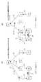
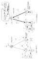
さて、次に、以下では、上述したVHA/THA/EN/MNの個々の動作を前提として、図18により前述したように端末3がローミング先のパケット網2のEN“4”の在圏ゾーンに位置しているときに、例えば図19に示すように、ホーム網1のEN“1”の在圏ゾーンに位置する別の端末3(以下、説明の便宜上、ローミング中の端末3を端末3a、ホーム網1に存在する別の端末3を端末3bと表記する)がローミング中の端末3aと通信を行なう場合の動作について考える。
【0232】
従って、この場合、端末3aは、ローミング先のTHA21bに「PCOA」を、ホーム網1のVHA10には「VCOA」を登録していることになる。
まず、端末3bは、端末3aの現在の移動先アドレス(COA)を知らないため、ホームアドレス(MNホームアドレス)宛にパケット(ユーザパケット)を送信することになる。このホームアドレス宛のパケットが、最寄りのEN“1”で受信されると、EN“1”では、図25により上述したステップD3及びD4にてNoと判定され、図26により上述したステップD17,D23及びD25にていずれもNoと判定されることになる。
【0233】
従って、EN“1”は、受信ユーザパケットをVHA10へ向けて転送するとともに、受信パケットのDA(MNホームアドレス)をDA、つまり、VHA10宛のBR-M3メッセージを発行してVHA10に対して「キャッシュ」を要求する。VHA10では、受信したユーザパケットを「VCOA」宛にカプセル化して転送するとともに、BR-M3メッセージに対する応答としてEN“1”宛のキャッシュ通知メッセージを発行する(図19中に示す点線矢印91参照)。
【0234】
これらの各処理は、ユーザパケットについては図23により上述したステップB3のNoルート,ステップB5のYesルート,ステップB7のNoルート,ステップB10のNoルート及びステップB13のYesルートを通る各処理に相当し、BR-M3メッセージについては図23により上述したステップB3のNoルート,ステップB5のYesルート,ステップB7のYesルート,図24により上述したステップC2のNoルート,ステップC3のNoルート,ステップC4のYesルート,ステップC21のYesルートを通る各処理に相当する。
【0235】
これにより、ユーザパケットは例えば図19に示すようにEN“2”へルーティングされ、EN“1”では、VHA10からのキャッシュ通知メッセージにより通知された「キャッシュ」をキャッシュテーブル44に登録する。その結果、EN“1”は、図19中に太実線矢印92で示すように、以降、VHA10に代わって端末3a宛のユーザパケットを「VCOA」でカプセル化してVHA10を経由させることなく転送すること(ルート最適化)が可能となる。
【0236】
次に、EN“2”は、上述のごとくVHA10にて「PCOA」でカプセル化されたユーザパケットをEN“3”へ転送し、EN“3”は、そのユーザパケットをTHA21bへ向けてルーティングするとともに、THA21b宛のBR-M3メッセージを発行してTHA21bに対して「キャッシュ」を要求することになる。
なお、このときのEN“2”での処理は、図25により前述したステップD3のNoルート,ステップD4のNoルート,図26により前述したステップD17のNoルート,ステップD23のYesルート及び図25により前述したステップD12のYesルートを通る各処理に相当し、EN“3”での処理は、図25により前述したステップD3のNoルート,ステップD4のNoルート,図26により前述したステップD17のNoルート及びステップD23のNoルートを通る各処理に相当する。
【0237】
これにより、THA21bは、受信したユーザパケットを「PCOA」でカプセル化してEN“4”に向けてルーティングするとともに、BR-M3メッセージに対する応答としてEN“3”宛のキャッシュ通知メッセージを発行する(図19中に示す点線矢印93参照)。このときの各処理も、ユーザパケットについては図23により上述したステップB3のNoルート,ステップB5のYesルート,ステップB7のNoルート,ステップB10のNoルート及びステップB13のYesルートを通る各処理に相当し、BR-M3メッセージについては図23により上述したステップB3のNoルート,ステップB5のYesルート,ステップB7のYesルート,図24により上述したステップC2のNoルート,ステップC3のNoルート,ステップC4のYesルート,ステップC21のYesルートを通る各処理に相当する。
【0238】
これにより、ユーザパケットは図19に示すようにEN“4”経由でローミング中の端末3aへ正しく転送され、EN“3”では、THA21bからのキャッシュ通知メッセージにより通知された「キャッシュ」をキャッシュテーブル44に登録する。その結果、EN“3”も、図19中に太実線矢印94で示すように、以降、THA21bに代わって端末3a宛のユーザパケットを「PCOA」でカプセル化してTHA21bを経由させることなく転送すること(ルート最適化)が可能となる。
【0239】
つまり、端末3bから送信されたユーザパケットは、最終的に、図20に示すような経路を辿ってローミング中の端末3aに届くことになる。従って、パケットの転送遅延が最小限に抑制されるとともに、VHA/THAの処理負荷がENに分散されることになって大幅に軽減されることになる。特に、この場合は、従来のように、パケット転送ルートがTHAを経由するルートに制限されず、THAにパケットが集中することがないので、その効果は極めて大きい。
【0240】
なお、上記のEN“4”での処理は、図25により前述したステップD3のNoルート,ステップD4のNoルート,ステップD7のNoルート,ステップD12のYesルートを通る各処理に相当する。
さて、次に、図20に示すように、端末3aと端末3bとが通信を行なっている状態で、例えば図21に示すように、THA21bとは異なるTHA21aが収容するEN“5”の在圏ゾーンへ移動した場合を考える。
【0241】
この場合、端末3aは、その移動によって、EN“5”から「ルータ広告」を受信するようになる。すると、端末3aは、その「ルータ広告」に含まれているENアドレスがそれまでに受信していたものと異なるために、位置が変わったことを認識する。また、THAアドレスについては、この例では、これまでと異なるアドレスを受信することとなる。
【0242】
しかし、この場合は、ローミング先のパケット網2内の移動であるため、M3ネットワークアドレスはそれまでに受信していたものと同一である。従って、端末3aは、図18及び図22を用いて前述したように、最初のTHAアドレスのTHA21bへ位置登録を行なうことになり、位置登録先のTHAを切り替えることはしない。
【0243】
ただし、THAは切り替えないが、ENアドレスは変わっているので、「PCOA」は新しくなる。このため、端末3aは、この新しい「PCOA」を元のTHA21bに通知することになる(図21中の点線矢印95参照)。なお、以上の端末3aでの処理は、図22により前述したステップA2のNoルート,ステップA3のNoルート,ステップA6のYesルートを通る各処理に相当する。
【0244】
一方、上記の新しい「PCOA」を受けたTHA21bは、自己がもつキャッシュテーブル44に登録されている該当「キャッシュ」を更新するとともに、更新した「キャッシュ」に対応する通信中ENアドレスデータ62bをDAとするキャッシュ更新メッセージを発行して、通信中EN“3”に通知する(図21中の点線矢印96参照)。
【0245】
なお、以上の処理は、図24により前述したステップC2のYesルート,ステップC5のNoルート,ステップC6のYesルート,ステップC8のYesルート,ステップC11のYesルート及びステップC12のNoルートを通る各処理に相当する。
これにより、EN“3”の「キャッシュ」がTHA21bから通知された「キャッシュ」に書き換えられる(図27のステップE6参照)。その結果、以降に到着した端末3a宛のパケットをEN“3”が受信したときには、新しい「PCOA」でカプセル化(図25のステップD13参照)して送信することになり、端末3a最新の移動先に正しく届けることができる。
【0246】
なお、上述した実施形態では、パケット網1をホーム網とする端末3aがパケット網2へローミングする場合について説明したが、勿論、パケット網2をホーム網とする端末3がパケット網1へローミングする場合も、上記と同様である。
以上のように、本実施形態によれば、ENがVHA/THAで管理している「キャッシュ」を受けてその「キャッシュ」に基づきそのVHA/THAに代わって端末3宛のパケットルーティングを行なうので、端末3宛のパケットを、VHA/THAを経由せずに、直接、在圏ENに転送できることになり、高速ハンドオーバとパケット転送ルートに制限の無いルート最適化とが可能になる。
【0247】
特に、本実施形態の場合は、通信中ENアドレスをキャッシュテーブル44において複数分保持できるようにしておくことで、1台の端末3に対して複数の通信中ENにVHA/THAによるルーティングを代替させるよう設定することができるので、従来のように特定のVHA/THAにパケットが集中するようなことがなく、VHA/THAの処理負荷をENに分散させてその負荷を大幅に軽減することが可能である。
【0248】
また、ローミング中の端末3は、在圏ENからの「ルータ広告」に含まれるTHAアドレスが自己の移動に伴って変化してもM3ネットワークアドレスが変化していなければ、自身が同じローミング先の網2(1)内に位置していると認識して、「COA(「PCOA」)の通知(登録)先を、同じTHAに維持することができるので、従来のように移動に伴って位置登録先THAの切り替えが頻繁に発生することも防止でき、高速ハンドオーバ性をさらに向上することができる。
【0249】
さらに、端末3による位置登録先THAが端末3の移動に関わらず上述のごとく同じTHAに維持される場合であっても、端末3のTHAに対する現在位置の更新登録に応じて必要な「キャッシュ」が通信中ENに逐次提供されて相互の同期がとられるので、通信中ENは、パケット転送ルートを、THAを経由しない新たな在圏ENに到るルートに適切且つ迅速に変更することが可能である。従って、THAの処理負荷をさらに抑制しながら高速ハンドオーバを実現することができる。
【0250】
また、端末3宛のパケットを受信したENは、「キャッシュ」が無い場合にVHA/THAへ必要な「キャッシュ」を要求するので、どのENも、VHA/THAによるパケットルーティングを代替することができ、VHA/THAのパケットルーティングを代替するENが1箇所に固定されず、特定のENにパケットが集中してその負荷が増大することも無い。従って、この場合、ENとVHA/THAとの双方の負荷を軽減できることになる。
【0251】
さらに、このとき、VHA/THAは、「キャッシュ」の要求を受けたENのみにキャッシュ情報を提供するので、不要な「キャッシュ」の転送を防止することができ、網内のトラフィック量の増大を抑制することも可能である。また、VHA/THAは、キャッシュテーブル44に保持する「通信中ENアドレス」によって、「キャッシュ」を更新/削除すべきENを把握しておくので、新しいCOAの通知を受けた場合の該当通信中ENの「キャッシュ」を誤ることなく更新できる。従って、パケットルーティングの信頼性、つまり、通信品質を向上することができる。
【0252】
さらに、通信中ENでは、端末3宛のパケットを受信する毎に、上記の「キャッシュ」のライフタイム(有効期限)をリフレッシュするので、通信中に「キャッシュ」の有効期限が切れて正常な通信を維持できなくなることを回避することができ、さらに、パケットルーティングの信頼性、つまり、通信品質を向上することができる。
【0253】
また、通信中ENは、通信が終了して上記の「キャッシュ」の有効期限が切れると、当該「キャッシュ」を削除するとともに、その「キャッシュ」を受けたVHA/THAに対して該当「キャッシュ」の「通信中ENアドレス」の削除を要求し、この要求を受けたVHA/THAが、自己のキャッシュテーブル44で保持している該当「通信中ENアドレス」を削除するので、EN及びVHA/THAにおいて不要な情報をいつまでも保持しておくことがなく、それぞれに必要なメモリ容量などを削減して、その小型化を図ることができる。
【0254】
(B)変形例の説明
上述した実施形態では、ローミング先において端末3が移動してENアドレス及びTHAアドレスに変化があっても、原則として、M3ネットワークアドレスに変化が無い限り、それらの変化を無視して、最初に位置登録を行なったTHAに対してのみ位置登録を行なっているが、或る特定の条件(付加的条件)を満足した場合には、位置登録先のTHAの切り替えを行なうようにすることも可能である。なお、「THAの切り替え」とは、受信した「ルータ広告」に含まれるTHAアドレス,ENアドレスから新しく「VCOA」,「PCOA」を作成し、VHAにはホーム位置登録メッセージにより「VCOA」を、THAには在圏位置登録メッセージにより「PCOA」を送信して各COAを登録することを意味する。
【0255】
以下では、その例について詳述する。ただし、以下の例では、例えば、図30に示すように端末3がM3v6ネットワーク1からローミング先の他網(M3v6他ネットワーク)2へ移動してゆく状況を想定する。なお、この図30において、端末3のホーム網1のアドレス(M3ネットワークアドレス)は、「100.50」、ローミング先のパケット網2のM3ネットワークアドレスは「200.50」、THA11a,11b,21a,21bのアドレスは、それぞれ順に、「10.1」,「20.1」,「30.1」,「40.1」、EN12(EN“1”,“2”,“5”〜“8”)のアドレスは、それぞれ順に、「1.1」,「2.1」,「5.1」,「6.1」,「7.1」,「8.1」と仮定し、端末3のインタフェースIDは“3”と仮定する。
【0256】
従って、図30中に示すように、EN12から端末3が受信する「ルータ広告」に含まれるENアドレスは、その移動に伴って、「1.1」→「1.1」→「2.1」→「5.1」→「6.1」→「7.1」→「8.1」と遷移してゆき、同じく、THAアドレスは「10.1」→「10.1」→「20.1」→「30.1」→「30.1」→「40.1」→「40.1」と遷移してゆく。
【0257】
また、M3ネットワークアドレスは、「100.50」→「100.50」→「100.50」→「200.50」→「200.50」→「200.50」→「200.50」→「200.50」と遷移してゆく。そして、このような移動に伴って、端末3で作成する「PCOA」は、「1.3」→「1.3」→「2.3」→「5.3」→「6.3」→「7.3」→「8.3」と遷移してゆき、「VCOA」は、「10.3」→「10.3」→「30.3」→「30.3」→「40.3」→「40.3」と遷移してゆくことになる。
【0258】
(B1)第1変形例(一定時間経過毎にTHAの切り替え判断を行なう場合)
かかる状況を前提として、本第1変形例の端末3では、例えば図31に示すように、パケット網2へローミングインした後、一定周期T毎に、THAアドレスが変化しているか否かを判断する。そして、一定周期T経過時にTHAアドレスが変化していれば、端末3は、そのときに初めて、位置登録先のTHAをTHA21aからTHA21bに切り替える。
【0259】
即ち、この例では、端末3は、THAアドレスが変化した時点T1では、THAの切り替えは行なわず、一定周期T経過時点T2において、初めて、その時のENアドレス(=「7.1」のプレフィックス部分(“7”)と自己のインタフェースID(=“3”)との組み合わせにより、「PCOA」=「7.3」を作成し、この「PCOA」をTHA21aではなくTHA21bへ通知する(点線矢印96参照)とともに、その時のTHAアドレス(=「40.1」)のプレフィックス部分(“40”)と自己のインタフェースID(=“3”)との組み合わせにより、「VCOA」=「40.3」を作成して、この「VCOA」をホーム網1のVHA10へ通知するのである(点線矢印97参照)。
【0260】
このような動作は、例えば端末3のルータ広告メッセージ処理部34Cの基本アルゴリズム(図22に示すステップA1〜A8)に、図32に示すTHAアドレスチェックアルゴリズム(ステップA9〜A13)及び図33に示すフラグ設定アルゴリズム(ステップA14〜A18)を付加することで実現できる。
即ち、この場合、図33に示すように、端末3では、現時刻情報(nowtime)を読み出し(ステップA14)、前回THAアドレスチェック時刻情報(oldtime)を読み出し(ステップA15)、これらの時刻情報の差分(nowtime−oldtime)が周期Tよりも大きいか否かをチェックする(ステップA16)。
【0261】
そして、上記の各時刻情報の差分が時間情報(周期)Tよりも大きければ、一定周期Tが経過したことになるので、THAアドレスフラグチェックフラグを“on”とし(ステップA16のYesルートからステップA17)、前回THAアドレスチェック時刻情報(oldtime)を現時刻情報(nowtime)に更新して処理を終える(ステップA18)。なお、上記の各時刻情報の差分が時間情報T以下であるときは、そのまま処理は終了する(ステップA16のNoルート)。
【0262】
以上の処理(一定周期カウントアルゴリズム)を端末3は繰り返し実行することにより、一定周期T経過毎にTHAアドレスチェックフラグを“on”に設定することになる。なお、上記の時刻情報(nowtime,oldtime),時間情報T,THAアドレスチェックフラグは、それぞれ、情報格納レジスタ341に格納されるようにすればよい。
【0263】
かかる状態で、端末3(ルータ広告メッセージ処理部34C)は、元のTHA21a宛の在圏位置登録メッセージを発行してTHA21aへ位置登録を行なうと(ステップA8)、続いて、THAアドレスチェックフラグが“on”になっているか否かをチェックし(ステップA9)、THAアドレスチェックフラグが“off”になっていれば、その時点でTHAアドレスが変化していても、現THAアドレスは元のTHAアドレスとし(ステップA9のNoルートからステップA13)、THAアドレスチェックフラグを“off”に解除する(ステップA12)。
【0264】
これに対し、THAアドレスチェックフラグが“on”になっていれば、次に、ルータ広告処理部34Cは、「ルータ広告」に含まれるTHAアドレスのプレフィックス部分が元のTHAアドレス(例えば、情報格納レジスタ341に格納される)のプレフィックス部分と一致するか否かをチェックし(ステップA9のYesルートからステップA10)、一致していれば、THAアドレスに変化が無いので、この場合も、現THAアドレスは元のTHAアドレスとし(ステップA10のYesルートからステップA13)、THAアドレスチェックフラグを“off”に解除する(ステップA12)。
【0265】
一方、上記の各プレフィックス部分が一致していなければ、THAアドレスが変化しているので、端末3(ルータ広告メッセージ処理部34C)は、上述のごとく「PCOA」を新しいTHAアドレスをもつTHA21bへ在圏位置登録メッセージにより通知するとともに、「VCOA」をホーム網1のVHA10へホーム位置登録メッセージにより通知して(ステップA10のNoルートからステップA11)、THAアドレスチェックフラグを“off”に解除する(ステップA12)。
【0266】
つまり、本変形例では、ゲートノード識別情報監視手段としての機能を果たすルータ広告解析部342が、上記のフラグ設定アルゴリズム(ステップA14〜A18)およびTHAアドレスチェックアルゴリズム(ステップA9〜A13)を実行することにより、所定の付加的条件下においてTHAアドレスが変化したか否かを検知する条件付監視手段として構成されていることになる。
【0267】
そして、この場合、現在位置通知手段としての機能を果たす位置登録メッセージ作成部343が、上記ルータ広告解析部342にて上記の付加的条件下におけるTHAアドレスの変化が検知されると、M3ネットワークアドレスに変化が無い場合であっても、変化後のTHAアドレスによって識別される新たなTHAに自己の現在位置情報(PCOA)を通知する条件付通知手段としての機能を有していることになる。
【0268】
このように、本第1変形例の場合は、一定周期T経過時にTHAアドレスが変化しているという一定の条件を満足すると、位置登録先THAの切り替えを行なうので、例えば、位置登録先THAを維持することにより、端末3とTHAとの距離が長距離になってしまった場合などにおいて、最寄りのTHAが変化する毎に位置登録を行なう場合よりもその登録頻度を削減しながら、位置登録先THAの最適化、つまり、ハンドオーバ時間の最適化を有効に図ることができる。
【0269】
(B2)第2変形例(非通信中にTHAの切り替え判断を行なう場合)
次に、上述したTHAの切り替え判断を、端末3の非通信中に行なう場合について説明する。
即ち、例えば図34に示すように、「ルータ広告」に含まれるTHAアドレスが「30.1」から「40.1」に変わった時点T3では、端末3は、まだ通信中であるため、THAの切り替えを行なわない。その後、非通信中となった後(時点T4の後)で、「ルータ広告」を受信すると、上記の例と同様にして端末3はTHAの切り替えを実行する(THA21bに「PCOA」を通知し、VHA10に「VCOA」を通知する)。
【0270】
このような動作は、上記のTHAアドレスフラグチェックを“on”にする契機だけが異なっているため、図33に示すフラグ設定アルゴリズムに代えて、例えば図35に示すように、通信中でないときにのみ(ステップA19でNoと判定された場合にのみ)、THAアドレスチェックフラグを“on”にする(ステップA20)フラグ設定アルゴリズムを用いれば実現できる。なお、この図35に示すアルゴリズムは、図32に示すTHAアドレスチェックアルゴリズムとは独立に、(例えば周期的に)起動される。
【0271】
このように、本第2変形例の場合は、位置登録先THAの切り替えが必ず端末3の非通信中であるときに実施されるので、通信中の切り替え発生による通信品質の劣化は生じない。従って、通信品質の劣化を防止しながら、ハンドオーバ時間の最適化を図ることができる。
(B3)第3変形例(非通信中にTHAの切り替え判断を行なう場合)
次に、上記のTHAの切り替え判断を、トラフィック量が所定のしきい値以下であるときに行なう場合について説明する。
【0272】
即ち、例えば図36に示すように、端末3において、その通信トラフィック量を監視しておき、THAアドレスが変化してもその時のトラフィック量がしきい値を超えていれば、THAの切り替え判断は行なわず(時点T5参照)、トラフィック量が所定のしきい値以下になって、初めてTHAの切り替え判断を行なう(時点T6参照)。
【0273】
このような端末3の動作は、図33に示すフラグ設定アルゴリズムに代えて、例えば図37に示すように、監視したトラフィック量(例えば、情報格納レジスタ341に格納すればよい)を読み出し(ステップA21)、そのトラフィック量がしきい値以下であるときにのみ(ステップA22でYesと判定された場合にのみ)、THAアドレスチェックフラグを“on”にする(ステップA23)フラグ設定アルゴリズムを用いれば実現できる。なお、この図37に示すアルゴリズムも、図32に示すアルゴリズムとは独立に、(例えば周期的に)起動される。
【0274】
このように、本第3変形例の場合は、位置登録先THAの切り替えが、必ず通信トラフィック量が所定値以下であるときに実施されるので、通信への影響(通信帯域の圧迫等)を最小限に抑制しながら、ハンドオーバ時間の最適化を図ることができる。
(B4)第4変形例(通信中トラフィックのタイプによってTHAの切り替え判断を行なう場合)
次に、上記のTHAの切り替え判断を、通信中トラフィックのタイプ(種別)によって行なう場合について説明する。
【0275】
即ち、例えば図38に示すように、端末3が“http”,“VOIP”の2種のトラフィックタイプの通信を行なっており、“http”トラフィックが存在する間は、THAアドレスに変化があっても、THAの切り替え判断は行なわず(時点T7参照)、その後に、“http”トラフィックが無くなり、“VOIP”トラフィックのみとなったときに、初めて、「ルータ広告」受信時のTHAの切り替え判断を行なう(時点T8参照)。
【0276】
このような端末3の動作は、図33に示すフラグ設定アルゴリズムに代えて、例えば図39に示すように、トラフィック種別を監視して情報格納レジスタ341等にその種別情報を格納するようにしておき、その種別情報を読み出し(ステップA24)、現在有効なトラフィック種別が“VOIP”のみのとき(ステップA25でYesと判定された場合)に、THAアドレスチェックフラグを“on”にする(ステップA26)フラグ設定アルゴリズムを用いれば実現できる。
【0277】
なお、“VOIP”トラフィックであるか否かの判断は、受信パケットの「トラフィッククラス」フィールド712(図8参照)に設定されている値を参照することで行なわれる。また、この図39に示すアルゴリズムも、図32に示すTHAアドレスチェックアルゴリズムとは独立に、(例えば周期的に)起動される。
このように、本第4変形例の場合は、通信中のデータトラフィックタイプが“VOIP”という多少のパケットロスであれば許容できるデータトラフィックタイプであるときにのみ、位置登録先THAの切り替えが実施されるので、位置登録先THAの切り替えを行なっても許容範囲内での通信品質劣化で済み、ハンドオーバ時間は最適化することができる。
【0278】
なお、“VOIP”以外にも、ハンドオーバにより多少の通信品質劣化が許容されるトラフィックタイプがあれば、そのタイプの通信のみが行なわれている間に、位置登録先THAの切り替えを行なうことも、勿論、可能であり、同様の作用効果が得られる。
(B5)第5変形例(端末3のアプリケーションが動作していないときにTHAの切り替え判断を行なう場合)
次に、上記のTHAの切り替え判断を、端末3のアプリケーションが動作していないときに行なう場合について説明する。
【0279】
即ち、例えば図40に示すように、端末3において、アプリケーションの動作数を監視しておき、動作中のアプリケーション数が“0”以外のときには、THAアドレスに変化があってもTHAの切り替え判断は行なわず(時点T9参照)、動作中のアプリケーション数が“0”となっているときに初めて、「ルータ広告」受信時のTHAの切り替え判断を行なう(時点T10参照)。
【0280】
このような端末3の動作は、図33に示すアルゴリズムに代えて、例えば図41に示すように、監視したアプリケーション動作数情報を読み出し(ステップA27)、現在動作中のアプリケーション数が“0”であるとき(ステップA28でYesと判定された場合)にのみ、THAアドレスチェックフラグを“on”にする(ステップA29)フラグ設定アルゴリズムを用いれば実現できる。なお、この図41に示すアルゴリズムも、図32に示すTHAアドレスチェックアルゴリズムとは独立に、(例えば周期的に)起動される。
【0281】
このように、本第5変形例では、通信に使用するアプリケーションの使用状態を監視し、上記の付加的条件としてアプリケーションが未使用であるときにのみ、つまり、端末3自体の処理能力に余裕があるときに実施されるので、位置登録先THAの切り替えが行なわれるので、やはり、通信中の通信品質劣化を最小限に抑制しながら、ハンドオーバ時間の最適化を図ることができる。
【0282】
上記の(B1)第1変形例〜(B5)第5変形例により上述した各条件は適宜組み合わせて設定してもよい。即ち、上記の一定周期,非通信中,通信トラフィック量,データトラフィックタイプ,アプリケーションの使用状態の各条件のうち、任意の条件の組み合わせによって特定される時期(組み合わせ条件下)においてTHAアドレスが変化している場合にのみ、位置登録先THAの切り替えを実施するようにしてもよい。
【0283】
例えば、一定周期T経過時に端末が非通信中であるときや、特定のデータトラフィックタイプの通信中にそのトラフィック量が所定値以下であるとき等においてのみ、位置登録先THAの切り替えを実施するようにすることが可能である。いずれの場合も、より有効にハンドオーバによる通信品質の劣化を抑制することが可能になる。
【0284】
(C)その他
なお、上述した実施形態では、ENが「キャッシュ」を要求する相手(VHA/THA)のアドレスを知らない場合を想定したものであるが、例えばアドレスの割り当てが正確に階層化されているような場合には、ENが、受信パケットのアドレス領域の上位数桁と、ある特定のインタフェースIDとを組み合わせて宛先アドレスを決定する方法も考えられる。
【0285】
また、別の方法として、VHA/THAのアドレスをENが予め知っている場合には、そのアドレスをBR-M3メッセージのアドレスとして送信しても良い。
(D)第2実施形態の説明
図42は本発明の第2実施形態に係るパケット網の構成を示すブロック図で、この図42に示すパケット網1′は、「MIPv6」に準拠する網で、複数のノード(ルーティングノード)から成り、そのうちの特定ノードが移動端末(MN;Mobile Node)3′の位置管理機能を有するホームエージェントノード(HA)10′として構成されるとともに、他のノードがルータ(R)13′(この図42では、「R1」〜「R5」の5台を図示している)として構成されている。
【0286】
そして、この場合も、MN3′は、最寄りのルータ(在圏ノード)13′から受信されるルータ広告(RA)に含まれる当該ルータ13′のIPアドレスに基づく現在位置情報(COA)を作成してHA10に通知することにより、逐次、HA10′に対して位置登録を行なうようになっており、これにより、HA10′は、常に、MN3′宛の受信パケットをMN3′の現在位置に対応する在圏ノード13′へ正しくルーティング(ハンドオーバ)することができ、MN移動中の正常なモバイルIP通信(音声,データ通信を含む)を可能にしている。なお、この図42には図示していないが、ルータ13′に接続してMN3′と通信しうる相手端末には、他のMN3′だけでなく固定端末も含まれる。
【0287】
具体的に、上記のHA10′は、MN3′から上記のCOAの通知(位置登録)を受けることにより、そのMN3′のCOAを結合(バインディング)キャッシュ(Binding Cache)と呼ばれる情報の一部として管理するとともに、到着(受信)したMN3′宛のパケットが示す宛先アドレス(DA)に対応する「COA」を本「キャッシュ」において検索し、該当「COA」でカプセル化して転送(ルーティング)する機能を有するものである。
【0288】
また、各ルータ13′は、それぞれ、在圏ゾーンに位置するMN3′と無線回線にて通信することにより、そのMN3′との間でパケットの送受を行なえるもので、受信パケットに付与されている宛先アドレス(DA)に基づいてその受信パケットを次ホップ先(他ルータ13′もしくはMN3′)へルーティングする機能を有している。なお、以下では、HA10′及びMN3′を、第1実施形態と同様に、それぞれ、HA及びMNと符号を省略して表記する場合がある。
【0289】
そして、上記のHA10′及びルータ13′は、それぞれ、その要部に着目すると、例えば図43に示すように、入力処理部41,パケット種別識別部42A,結合(バインディング)キャッシュ(Binding Cache)検索部43A,結合(バインディング)キャッシュ(Binding Cache)テーブル44A,カプセル化処理部45,ルータ処理部46(ルーティングテーブル46a,出方路決定部46b),出力処理部48,タイマ処理部49A及び制御メッセージ処理部50Aをそなえて構成されている。
【0290】
ここで、上記の入力処理部41は、図2に示すものと同様に、到着(受信)パケットのIPレイヤ以下の処理を行なうためのもので、例えば、イーサネットであれば自ノード宛のMAC(Media Access Control)アドレスが付与されたパケットを取り込んで、そのパケットのフレーム自体の正常性をチェックする処理を行なう機能を装備するものである。
【0291】
また、パケット種別識別部42Aは、この入力処理部41で受信された正常なパケットの種別(主に、自ノード宛のメッセージか他ノード宛のメッセージか)を、その宛先アドレス(DA)を参照して識別するためのもので、ここでは、自ノード宛のメッセージ(パケット)であれば制御メッセージ処理部50Aへ、他ノード宛のメッセージであれば、バインディングキャッシュ検索部43Aへそれぞれ転送されるようになっている。
【0292】
さらに、図43において、結合(バインディング)キャッシュテーブル(以下、単に「キャッシュテーブル」という)44Aは、本実施形態においても、基本的に、「MIPv6」ベースで作成される「キャッシュ」をMN3′のホームアドレス(MNホームアドレス)別にテーブル形式のデータとして保持するもので、例えば、RAMやレジスタ等の所要の記憶デバイスによって構成される。
【0293】
ここで、このキャッシュテーブル44Aには、この場合も、基本的に、“COA”(128ビット),“lifetime”(32ビット),“Home registration flag”(1ビット),“router flag”(1ビット),“prefix length”(7ビット),“Sequence Number”(16ビット),“Recent Usage Information”(1ビット),“last BR time”(128ビット)等のキャッシュデータが保持されるが、HAにおいては、例えば図44(B)に示すように、MNホームアドレス毎に、「現在のCOA」とその有効期限を表す“lifetime1”に加えて、MNの「通信開始時(過去)のCOA」とその有効期限を表す“lifetime2”も保持されるようになっている。
【0294】
つまり、本実施形態のキャッシュテーブル44Aは、MNの移動に伴う複数のCOA(「現在のCOA」及び「通信開始時のCOA」)を保持する位置情報保持部44A−1としての機能と、少なくとも「通信開始時のCOA」の有効期限に関する情報(“lifetime2”)を記憶する有効期限情報記憶部44A−2としての機能とを果たしていることになる。
【0295】
ここで、例えば、図44(A)に模式的に示すように、HAの通信エリア(在圏ゾーン)100′に存在するMNが、ルータ「R1」の在圏ゾーン13′−2,ルータ「R2」の在圏ゾーン13′−1の順に移動する場合(点線矢印97参照)を想定する。なお、各ノードのIPアドレスを、第1実施形態での表記法と同様に、x(ネットワークID).y(MNのインタフェースID)と表記することにして、HAのネットワークIDを“144”、ルータ「R2」のネットワークIDを“211”、ルータ「R1」のネットワークIDを“112”とすると、HAのアドレスは“144.y”、ルータ「R2」のアドレスは“211.y”、ルータ「R1」のアドレスは“112.y”と表される。
【0296】
そして、MNのインタフェースID(MNに固有の識別子)を“50”とすると、MNは、ルータ「R1」の在圏ゾーン13′−2に移動してルータ「R1」に接続したときに、COA=“112.50”を作成してHAに通知(位置登録)する。なお、この時点では、キャッシュテーブル44Aに「通信開始時のCOA」は登録されない。
【0297】
その後、MNがルータ「R1」に接続した状態で通信を開始すると(つまり、HAでMN宛のパケットが受信されると)、HAは、受信パケットの「トラフィック種別」を判断し、受信パケットがデータパケットであればそのときの「現在のCOA」及び“lifetime1”をコピーして、「通信開始時のCOA」及び“lifetime2”としてキャッシュテーブル44Aに登録する。
【0298】
かかる状態で、MNがさらに移動し、ルータ「R2」に接続すると、MNは新しいCOA=“211.50”を作成してHAに通知し、HAでは「現在のCOA」=「現在のCOA」を“112.50”から“211.50”に書き換える。なお、この際、「通信開始時のCOA」は変更されない(“112.50”のままである)。
ここまでの状態で、HAのキャッシュテーブル44Aには、図44(B)に示す登録内容をもつことになる。つまり、HAのキャッシュテーブル44Aには、図4(B)に示すように、「現在のCOA」として“211.50”が保持され、「通信開始時のCOA」として“112.50”が保持されることになる。
【0299】
なお、上記の“lifetime1”及び“lifetime2”は、いずれも、対応するCOA宛のパケットを受信しない間、定期的に減算され、最終的にその値が“0”になると(つまり、有効期限が切れると)、対応するCOA(キャッシュ)が削除される。ただし、対応するCOA宛のパケットを受信している間は、そのCOAを維持する必要があるので、パケット受信毎に“lifetime2”は“0”にならないよう予め決められた初期値等にリフレッシュ(更新)される。“lifetime1”の更新契機は、第1実施形態と同様である。これらの有効期限の更新はタイマ処理部49Aによって実施される。
【0300】
次に、バインディングキャッシュ検索部(以下、単に「キャッシュ検索部」ともいう)43Aは、入力パケットのIPヘッダ70(図7参照)に含まれる宛先アドレスを検索キーとして、上記のキャッシュテーブル44Aを検索してカプセル化処理部45でのカプセル化に必要な情報(COA等)を取得することができるものである。
【0301】
ただし、本実施形態のHAにおけるキャッシュ検索部43Aは、主として、次のような各機能を兼ね備えている。
▲1▼受信パケットの種別(例えば、トラフィック種別)を識別するトラフィック(パケット)種別識別部431としての機能
▲2▼「現在のCOA」及び“lifetime2”をそれぞれコピーして、「通信開始時のCOA」及び“lifetime2”としてキャッシュテーブル44Aに登録しうるコピー登録部432としての機能
▲3▼このトラフィック種別識別部431による識別結果(受信パケットのトラフィック種別)に応じて、キャッシュテーブル44Aにおける上記の「現在のCOA」及び「通信開始時のCOA」のいずれか一方を、カプセル化処理部45でのカプセル化に使用するCOAとして選択するCOA選択部(選択手段)433としての機能
ここで、上記の「トラフィック種別」の例としては、▲1▼或る程度のパケットロスが許容される特性をもつ音声パケット〔例えば、VOIP(Voice Over Internet Protocol)パケット〕や▲2▼或る程度のパケット転送遅延が許容される特性をもつデータパケット〔例えば、http(hyper text transfer protocol)データパケットやftp(file transfer protocol)データパケット等〕があり、これらはIPヘッダ70(標準ヘッダ71;図7参照)に含まれるtos(タイプ・オブ・サービス)フィールド〔「トラフィッククラス」フィールド712(図8参照)〕の値をそれぞれについて定義しておくことで識別することが可能である。なお、このように、「トラフィック種別」の識別にtos値を用いるのが、最も簡便な手法であり、HAの小型化も期待できる。
【0302】
具体的には、例えば、音声パケットは図45に示すようなフォーマットを有しており、ftpデータパケットは図46に示すようなフォーマットを有しているが、これらの図45及び図46において、「トラフィッククラス」フィールド712に、それぞれ音声パケット及びftpデータパケットを表す値を設定しておけば、これらのパケットの「トラフィック種別」(以下、「パケット種別」ともいう)をトラフィック種別識別部431において識別できることになる。
【0303】
つまり、この場合のトラフィック種別識別部431は、受信パケットの「トラフィック種別」が少なくともパケットロスを許容する特性をもつトラフィック種別及びパケット転送転送遅延を許容する特性をもつトラフィック種別のいずれであるかを識別するパケットロス/転送遅延特性識別部として機能することになる。
【0304】
なお、上記の「トラフィッククラス」フィールド712の値(tos値)は、例えば、MNと網管理者との間で予め取り決めを交わしておき、MNがパケットを生成するときにその取り決めに従ってMN側で設定してもよいし、予め網管理者と取り決めを交わしておき、パケットが流入してくる網1′の入口(エッジルータ)にポリシー制御機能を導入し、そのルータにおいて、全受信パケットにつき、送信元アドレス(SA),宛先アドレス(DA),使用プロトコル,送信(発信)元ポート番号,宛先ポート番号をチェックして「トラフィック種別」を識別し、tos値をその識別結果に応じた適切な値(トラフィック識別情報)に書き換えた(設定した)上で網1′内(HA宛)にパケットを転送(ルーティング)するようにしてもよい。
【0305】
後者の場合には、MNにおいて送信パケットのtos値を独自にセットする必要が無く、HAは、受信パケットに上記エッジルータにて設定し直されたtos値に基づいて「トラフィック種別」の識別が可能となるので、MNの処理能力に余裕をもたせることが可能である。なお、エッジルータでの「トラフィック種別」の識別結果は、勿論、パケットの「トラフィッククラス」フィールド712以外の部分に設定するようにしてもよい。
【0306】
また、図45及び図46において、上記の「送信元アドレス(SA)」はSAフィールド717に表示され、「宛先アドレス(DA)」はDAフィールド718に表示され、「使用プロトコル」は「ネクストヘッダ」フィールド(プロトコルフィールド)715に表示〔例えば、TCP(Transmission Control Protocol)なら“6”,UDP(User Datagram Protocol)なら“17”等〕される。
【0307】
同様に、「送信元ポート番号」はTCPヘッダ74又はUDPヘッダ76の発信元ポート番号フィールド761に表示され、「宛先ポート番号」は同じくTCPヘッダ74又はUDPヘッダ76の宛先ポート番号フィールド762に表示される。
なお、このように網1′の入口(エッジルータ)にポリシー制御機能を導入しない場合は、例えば、VOIPを使用する音声パケットは、通常、IPの上位レイヤにRTP(Real-time Transport Protocol)を用いるので、RTPヘッダ77(図45参照)を検出することにより、受信パケットが音声パケットであることを識別できる。
【0308】
ここで、RTPの音声符号化の種別は、ペイロードタイプフィールド771に表示され、図45には、音声パケットの一例として、ペイロード80(24バイト)に格納される音声データの音声符号化にG.723(dual rate speech corder for multimedia communications transmittimg at 5.3 and 6.3kbit/s)(ペイロードタイプ=4)を用いた場合のパケットフォーマットを示している。
【0309】
また、受信パケットの「トラフィック種別」は、MN側で使用するアプリケーションによって使用ポート番号が異なる場合には、上記のポート番号フィールド761,762に表示されている値から識別することもできる。
さらに、上記のプロトコルフィールド715には、上位アプリケーションの種別が表示されているので、その値により受信パケットの「トラフィック種別」を識別することもでき、また、音声パケット等のリアルタイムトラフィックには通常パケット長が短いという特徴があるので、パケット長(「ペイロード長」フィールド714)の値から「トラフィック種別」を識別することも可能である。
【0310】
さらに、「IPv4」のパケットであれば、そのヘッダに含まれる識別子(Identification)フィールドの値を「トラフィック種別」の識別に使用することも可能である。
そして、HAにおけるキャッシュ検索部43Aは、相手(宛先)MNの現在位置を知らないためにMNホームアドレスを宛先アドレス(DA)として送信されたパケットの当該MNホームアドレスを検索キーとして上記のキャッシュテーブル44Aを検索し、カプセル化処理部45でのカプセル化に用いるCOAとして、上述したごとくトラフィック種別識別部431によって識別される「トラフィック種別」に応じてCOA選択部433が「現在のCOA」及び「通信開始時のCOA」のいずれかを選択的に取得することになる。
【0311】
即ち、本実施形態のCOA選択部433は、例えば、受信パケットが或る程度のパケットロスを許容する特性をもつ音声(VOIP)パケットである場合、キャッシュ検索部43Aは、キャッシュテーブル44Aを検索して、受信パケットのMNホームアドレスに対応する「現在のCOA」を選択する一方、受信パケットが或る程度のパケット転送遅延を許容する特性をもつデータパケットである場合は、MNホームアドレスに対応する「通信開始時のCOA」(ただし、登録されていれば)を選択する端末位置情報選択部として機能するようになっているのである。
【0312】
次に、カプセル化処理部45は、COA選択部433で選択されたCOAを用いてキャッシュ検索部43Aから転送されてくる受信パケットをカプセル化するものであり、ルータ処理部46(ルーティングテーブル46a,出力方路決定部46b),出力処理部48は、図2により前述したものとそれぞれ同様の機能を有するもので、出方路決定部46bが、ルーティングテーブル46aを検索して、出力すべき物理インタフェースや下位レイヤでの宛先アドレス等を決定し、出力処理部48が、例えば、イーサネットの場合にはイーサネットフレームに必要なフレームチェックシーケンス符号を付けて、パケット(フレーム)送出を行なうようになっている。
【0313】
従って、本実施形態のカプセル化処理部45では、COA選択部433で選択されたCOAを用いてキャッシュ検索部43Aから転送されてくる受信パケットをカプセル化することになり、ルータ処理部46では、出方路決定部46bが、このようにカプセル化されたパケット(トンネルパケット)のヘッダ(カプセルヘッダ)の宛先情報(「現在のCOA」又は「通信開始時のCOA」)に基づいてルーティングテーブル46aのルーティング情報を検索して当該トンネルパケットの出力インタフェースを決定して、決定した出力インタフェースへ当該トンネルパケットを出力することになる。
【0314】
つまり、本実施形態のルータ処理部46は、COA選択部433で選択されたCOAに基づいて受信パケットをルーティングするルーティング手段として機能することになる。
これにより、音声パケットについては、例えば図47に模式的に示すように、MNから結合更新(Binding Update)メッセージにより登録(点線矢印23a参照)される「現在のCOA」、つまり、MNの最新のCOA(COA2=211.50)でカプセル化されてルーティングされることになるので、MNが現在接続しているルータ「R2」までのパケット転送ルートが最適化されて(実践矢印22,23参照)パケット転送遅延が最小となる。
【0315】
一方、データパケットの場合は、「通信開始時のCOA」(COA1=112.50)でカプセル化されてルーティングされることになるので、例えば図48に模式的に示すように、MNが通信継続中は通信開始時に接続していたルータ(以下、旧ルータという)「R1」に対して「スムースハンドオフ指示」を発行して旧ルータ「R1」に「現在のCOA」(COA2=211.50)を登録する(点線矢印24参照)ことにより旧ルータ「R1」からのパスを現在接続しているルータ「R2」まで伸ばしておく(実線矢印26参照)ことで、HAから旧ルータ「R1」までのパケット転送ルートは維持される(実線矢印25参照)ことになり、HAでパケット転送先をルータ「R1」から「R2」に切り替える場合(図47の場合)に比して、パケットロスを最小限に抑制することが可能となる。
【0316】
このように、本実施形態のHAは、受信パケットの「トラフィック種別」に応じて、受信パケットのカプセル化に用いるCOAを使い分けることにより、MNに対するハンドオーバの仕組み(方法)を変える(切り替える)ことができるようになっているのである。なお、以下では、上記の各ハンドオーバ方法のうち、前者(VOIPパケットについてのハンドオーバ方法)を第1のハンドオーバ方法、後者(データパケットについてのハンドオーバ方法)を第2のハンドオーバ方法ということがある。
【0317】
次に、図43において、タイマ処理部49Aは、上述したキャッシュテーブル44Aにおける“lifetime1”,“lifetime2”を更新する機能、即ち、入力処理部41でMNホームアドレスを宛先アドレス(DA)とするパケットが受信されない間は“Lifetime1”,“lifetime2”をそれぞれデクリメントし、パケットが受信されている間は“Lifetime1”,“lifetime2”が切れない(“0”にならない)ように更新(リフレッシュ)する有効期限リフレッシュ部491としての機能を有するとともに、“Lifetime1”,“lifetime2”が切れたときに、該当COAを削除するCOA(端末位置情報)削除部492としての機能を有するものである。
【0318】
また、制御メッセージ処理部50Aは、パケット種別識別部42Aにおいて自ノード宛のメッセージであると識別された(制御)メッセージを受けて、そのメッセージを処理するためのものである。このため、本制御メッセージ処理部50Aには、図43中に示すように、メッセージ種別判定部51A,モバイルメッセージ処理部52A,ルーティングメッセージ処理部53及びルータ広告メッセージ(RA)処理部54が設けられている。
【0319】
ここで、上記のメッセージ種別判定部51Aは、受信制御メッセージの種別を判定(識別)するためのもので、モバイルメッセージ(結合更新/応答メッセージ)とそれ以外のルーティングメッセージとを判別して、モバイルメッセージについてはモバイルメッセージ処理部52Aへ、ルーティングメッセージについてはルーティングメッセージ処理部53へそれぞれ振り分けられるようになっている。
【0320】
また、モバイルメッセージ処理部52Aは、受信したモバイルメッセージの種別を判定(解析)してそのメッセージ内容に応じた処理(キャッシュテーブル44Aへの情報登録や削除)を行なうためのもので、本実施形態では、そのメッセージ種別として、主に、▲1▼前記の結合更新(Binding Update)オプションを用いた結合更新(Binding Update)メッセージ〔位置登録メッセージ(スムースハンドオフ指示メッセージ)〕,▲2▼前記の結合応答(Binding Acknowledgement)オプションを用いた結合応答(Binding Acknowledgement)メッセージ(位置登録応答メッセージ)等がある。ただし、前者▲1▼のメッセージはMNからHA(旧ルータ13′)宛に送信されるメッセージであり、後者▲2▼のメッセージは、HA(旧ルータ13′)から位置登録メッセージ送信元のMN宛に送信されるメッセージである。
【0321】
そして、具体的に、このモバイルメッセージ処理部52Aは、MNからの位置登録メッセージ(スムースハンドオフ指示メッセージ)を受信すると、そのメッセージに含まれるCOAを「現在(最新)のCOA」として前記のキャッシュテーブル44Aの該当領域(MNホームアドレスに対応する領域)に登録(更新)するようになっている。
【0322】
ただし、HAにおけるモバイルメッセージ処理部52Aは、受信パケットがデータパケットである場合に、「通信開始時のCOA」がキャッシュテーブル44Aに未だ登録されていない場合には、その時の「現在のCOA」及び“lifetime 1”をコピーして「通信開始時のCOA」及び“lifetime 2”として登録することができるようにもなっている。
【0323】
つまり、図43において、キャッシュテーブル44A,タイマ処理部49A及びモバイルメッセージ処理部52Aから成る部分は、MNの移動に伴う複数のCOA(端末位置情報)を管理する端末位置管理手段として機能するのである。
なお、図43に示すルーティング処理部53及びRA処理部54は、それぞれ、図2により前述したものと同様のものであり、RIP(Routing Information Protocol)等のルーティングメッセージについての処理(例えば、網構成の変更等に伴うルーティング情報の更新等)がルーティングメッセージ処理部53によって実施され、在圏MNに対するルータ広告がルータ広告メッセージ処理部54によって発行されるようになっている。
【0324】
以下、上述のごとく構成された本第2実施形態のパケット網1′におけるハンドオーバ方法(HAの動作)について詳述する。ただし、以下では、説明の便宜上、受信パケットの「トラフィック種別」の識別に、前記のtos値を用いることを前提とする(例えば、tos=0で音声(VOIP)パケット、tos=1でデータパケットを表すものとする)。
【0325】
まず、HAでは、図50に示すように、パケットが入力処理部41において受信されると(ステップH1)、その受信パケットの正常性がチェックされたのち、パケット種別識別部42Aにおいて受信パケットが制御メッセージであるか否かが判定される(ステップH2,H3)。
その結果、受信パケットが制御メッセージであれば、その制御メッセージは、制御メッセージ処理部50Aのメッセージ種別判定部51Aに転送され、メッセージ種別判定部51Aにおいて、さらに、その制御メッセージがモバイルメッセージ(結合更新/応答メッセージ)であるか否かが判定される(ステップH3のYesルートからステップH4,H5)。
【0326】
この結果、受信制御メッセージがモバイルメッセージであれば、そのモバイルメッセージはモバイルメッセージ処理部52Aへ転送され、モバイルメッセージ処理部52Aは、受信モバイルメッセージが結合更新メッセージ(つまり、位置登録メッセージ)であれば、そのメッセージに含まれるCOAがMNの「現在のCOA」としてキャッシュテーブル44Aの該当領域に登録する(ステップH5のYesルートからステップH7)。なお、受信モバイルメッセージが結合応答メッセージであった場合、モバイルメッセージ処理部52Aは、そのメッセージ内容を解析して必要に応じて内部パラメータの変更等を行なう。
【0327】
ところで、パケット種別識別部42Aにおいて、受信パケットが制御メッセージでないと判定された場合(ステップH3でNoと判定された場合)、その受信パケットはキャッシュ検索部43Aに転送され、図51に示すように、キャッシュ検索部43Aは、受信パケットの宛先アドレス(MNホームアドレス)を検索キーとしてキャッシュテーブル44Aを検索し、MNホームアドレスに対応するCOA(「現在のCOA」及び「通信開始時のCOA」)を取得する(ステップH8)。
【0328】
さらに、キャッシュ検索部43A(トラフィック種別識別部431)は、パケット種別識別部42Aから転送されてきたパケットのtos値をチェックすることにより、そのパケット種別(音声パケットかデータパケットか)を識別(判定)する(ステップH9,H10)。
この結果、tos値が“0”で受信パケットが音声(VOIP)パケットであった場合(ステップH10でYesの場合)、キャッシュ検索部43Aは、COA選択部433によって、カプセル化に使用するCOAとして上記のステップH8で取得したCOAのうち「現在のCOA」を選択する(ステップH11)。
【0329】
これに対し、tos値が“1”で受信パケットが(ftp)データパケットであった場合(ステップH10でNoの場合)、キャッシュ検索部43Aは、上記のステップH8で取得したCOAに「通信開始時のCOA」が含まれている(つまり、キャッシュテーブル44Aに「通信開始時のCOA」が既に登録されている)か否かをチェックする(ステップH12)。
【0330】
その結果、未だ「通信開始時のCOA」が登録されていなければ(ステップH12でNoであれば)、上記受信パケットがMN宛の第1パケットである、即ち、この時点が「通信開始時」であることを意味するので、キャッシュ検索部43Aは、COA選択部433によって、上記第1パケットのカプセル化に使用するCOAとしてこの時点では「現在のCOA」を選択したのち(ステップH13)、コピー登録部432によって、その「現在のCOA」及び“lifetime1”をコピーして「通信開始時のCOA」及び“lifetime2”としてキャッシュテーブル44Aの該当領域に登録する(ステップH14)。
【0331】
以降は、キャッシュテーブル44Aに「通信開始時のCOA」が登録されているので、同じMN宛の受信パケット(第2パケット以降)については、カプセル化に使用するCOAとして、「通信開始時のCOA」が選択されることになる(ステップH12のYesルートからステップH15)。なお、この際、通信中に「通信開始時のCOA」が有効期限切れになり削除されてしまわぬように、“lifetime2”がタイマ処理部49A(有効期限リフレッシュ部491)によってリフレッシュされる(ステップH16)。
【0332】
さて、上述のごとくステップH11,H13又はH15においてキャッシュ検索部43A(COA選択部433)によって選択された「現在のCOA」又は「通信開始時のCOA」は、受信パケットとともにカプセル化処理部45へ転送され、カプセル化処理部45は、そのCOAで受信パケットをカプセル化してルータ処理部46へ転送する(ステップH17)。
【0333】
これにより、カプセル化されたパケット(トンネルパケット)は、出方路決定部46bにおいて、ルーティングテーブル46aのルーティング情報に基づいてその出力インタフェースが決定されたのち、出力処理部48を通じて決定した出力インタフェースへ送信される(ステップH18)。即ち、VOIPパケットは「現在のCOA」に該当するルータ(MNが現在接続しているルータ)13′へ向けてルーティングされ、データパケット(第2パケット以降)は「通信開始時のCOA」に該当する旧ルータ13′へルーティングされることになる。
【0334】
以上のようなHAでの動作を前提とすることにより、例えば図49(A)に示すように、MNが相手端末CN(Corresponding Node)とルータ「R3」,HA,ルータ「R1」経由で音声通話している(このとき、HAは音声パケットを「現在のCOA」(112.50)宛にカプセル化して転送している)状態(実線矢印22,23′参照)で、MNが通信を継続しながらルータ「R2」の在圏ゾーンへ移動したとすると(矢印27参照)、HAはMNから登録された最新のCOA(211.50)で相手端末CNからの音声パケットをカプセル化して転送する(第1のハンドオーバ方法を実行する)ことになる(実線矢印23参照)。
【0335】
一方、例えば図49(B)に示すように、MNが相手端末CN(Corresponding Node)とルータ「R3」,HA,ルータ「R1」経由でデータ通信している(このとき、HAはデータパケットを「現在のCOA」(112.50)宛にカプセル化して転送している)状態(実線矢印22参照)で、MNがデータ通信を継続しながらルータ「R2」の在圏ゾーンへ移動したとすると(矢印28参照)、HAは「通信開始時のCOA」(112.50)で相手端末CNからのデータパケットを引き続きカプセル化して転送する(第2のハンドオーバ方法を実行する)ことになる(実線矢印25参照)。
【0336】
この場合、MNがルータ「R2」の在圏ゾーンに移動した時点で、MNの「スムースハンドオフ指示」により旧ルータ「R1」に「現在のCOA」(211.50)が登録される(点線矢印24参照)ので、旧ルータ「R1」は、HAから「通信開始時のCOA」(112.50)宛に送られてきたパケットを「スムースハンドオフ指示」により登録されたCOA(211.50)で再カプセル化(スムースハンドオフ)して、MNが現在接続しているルータ「R2」へ転送する(実線矢印26参照)。
【0337】
なお、「スムースハンドオフ指示」を受けることによりスムースハンドオフを実行するルータ(ノード)13′のことを「アンカーポイント」という。この「アンカーポイント」は、MNの通信が一旦終了した場合は解除され(「スムースハンドオフ指示」によりMNから登録されたCOAが削除され)、次にMNが通信を開始して「スムースハンドオフ指示」を新たに発行したルータ13′が新たな「アンカーポイント」となる。
【0338】
以上のように、本実施形態によれば、HAにおいて、MNの移動に伴う複数のCOA(現在のCOA及び通信開始時のCOA)を管理しておき、MN宛のパケット種別を識別し、識別したパケット種別に応じて上記のCOAのいずれかを選択(つまり、カプセル化ヘッダの宛先を変更)して、そのCOAに基づいて受信パケットをルーティングすることにより、受信パケットの種別に応じてハンドオーバ方法を切り替えることができるので、ユーザが要求する複数種類の通信サービス品質(QoS:Quality of Service)を満足する通信を柔軟に実現でき、常にユーザの要求に最適なハンドオーバ方法を提供してQoSを大幅に向上させることが可能である。
【0339】
特に、本実施形態では、HAにおいて、受信パケットが音声パケットであればMNの「現在のCOA」を選択することにより、パケット転送遅延を最小限に抑制したハンドオーバを実施することができ、受信パケットがデータパケットであれば、MNの「通信開始時のCOA」を選択することにより、パケットロスを最小限に抑制したハンドオーバを実施することができるので、MNのユーザが利用する音声通話サービス,データ通信サービス等に応じた最適なハンドオーバ方法を提供することができるのである。
【0340】
また、本実施形態のHAでは、「通信開始時のCOA」の“lifetime2”を記憶しておき、MN宛の受信パケットを受信する毎にその“lifetime2”をタイマ処理部49(有効期限リフレッシュ部491)がリフレッシュするので、データパケット通信継続中に「通信開始時のCOA」が無効になることを防止することができ、当該データパケット通信の信頼性も向上している。
【0341】
さらに、上記のタイマ処理部49は、「通信開始時のCOA」の“lifetime2”が切れると、その「通信開始時のCOA」を位置情報削除部492が削除するので、「通信開始時のCAO」の記憶に必要な記憶容量を最小限に抑制して、HAの小型化にも大きく寄与している。
また、本実施形態のMNは、データパケットを受信している間、通信開始時に接続していたルータ13′(アンカーポイント)に対して「スムースハンドオフ指示」を発行するので、「スムースハンドオフ指示」を受けたルータ13′からMNが現在接続しているルータ13′まで通信パス(パケット転送ルート)を伸ばしておくことができ、ハンドオーバに伴うパケットロスを最小限に抑制することが可能である。
【0342】
(D1)第2実施形態の第1変形例の説明
さて、上述した第2実施形態では、「通信開始時のCOA」をパケットの宛先(MNホームアドレス)毎でしか管理していないので、同一宛先のデータパケットに対しては、全て、同一の転送ルートとなるようにHAにてカプセル化が行なわれることになる。
【0343】
このため、例えば、MN宛にある発信者が既にデータパケットの送信を行なっている状態で、別の発信者がMN宛にデータパケットを新たに送信しはじめると、MNが別のルータ13′の在圏ゾーンに移動した場合でも、そのデータパケットは、既存の発信者が送信したデータパケットのカプセル化に使用したものと同じ「通信開始時のCOA」でカプセル化されてしまい、既存の発信者が送信したデータパケットのパケット転送ルート(スムースハンドオフによるルート)と全く同じルートで転送されるという非効率な事態が生じる。
【0344】
そこで、本変形例では、宛先(MNホームアドレス)毎に加えて、受信パケットの発信元(送信元アドレス:SA)毎にも「通信開始時のCOA」を管理することにより、発信元毎にデータパケットのパケット転送ルートを変えられるようにして、発信者毎に、常に最短のアンカーポイント〔スムースハンドオフによるパケット転送を行なうルータ(ノード)〕をとることができるようにする。
【0345】
これは、例えば図52(B)に示すように、キャッシュテーブル44Aを、
MNホームアドレス毎に「現在のCOA」,その有効期限を示す“lifetime1”及びMNホームアドレスを一意に表すIDの組が登録・管理されるキャッシュテーブル441(Biding Cache1)と、上記IDと受信パケットの送信元アドレス(SA)との組み合わせ毎に「通信開始時のCOA」及びその有効期限を示す“lifetime2”の組が登録・管理されるキャッシュテーブル442(Binding Cache 2)とにより構成することで実現できる。
【0346】
そして、本変形例においても、図44(A)と同様に、HAのネットワークIDを“144”、ルータ「R2」のネットワークIDを“211”、ルータ「R1」のネットワークIDを“112”とすると、HAのアドレスは“144.y”、ルータ「R2」のアドレスは“211.y”、ルータ「R1」のアドレスは“112.y”と表され、MNのインタフェースIDを“50”とすると、MNは、ルータ「R1」の在圏ゾーン13′−2に位置する時はCOA=“112.50”、ルータ「R2」の在圏ゾーン13′−1に位置する時はCOA=“211.50”を作成して、それぞれ、HAに通知(位置登録)することになる。
【0347】
従って、仮に、MNがルータ「R1」の在圏ゾーン13′−2に位置する時にそのルータ「R1」に接続して、ルータ「R3」に接続している相手端末「CN1」(仮に、送信元アドレス=70.21とする)とデータ通信を開始したとすると、HAのキャッシュテーブル442には、図52(B)に示すように、相手端末「CN1」との「通信開始時のCOA」として“112.50”が登録されることになる。
【0348】
また、その後に、MNがルータ「R2」の在圏ゾーン13′−1に位置する時に、そのルータ「R2」に接続して、ルータ「R4」に接続している別の相手端末「CN2」(仮に、送信元アドレス=80.30とする)とデータ通信を開始したとすると、HAのキャッシュテーブル442には、別の相手端末「CN2」との「通信開始時のCOA」として“211.50”が登録されることになる。なお、“lifetime1”及び“lifetime2”の機能は、上述した第2実施形態で説明したものと同様である。
【0349】
そして、この場合のHAは、図54及び図55に示すフローチャートに従って動作することにより、発信者(「CN1」,「CN2」)毎に、常に最短のアンカーポイントをとるようにデータパケットの転送(ルーティング)を実施することができる。
即ち、図54に示すように、図50により前述したステップH7において、キャッシュテーブル441(Binding Cache1)に「現在のCOA」を登録し(ステップH7′)、図55に示すように、図51により前述したステップH8において、キャッシュ検索部43Aが、MNホームアドレス及びIDをキーにして各キャッシュテーブル441,442を検索して、MNホームアドレス及びIDに対応する「現在のCOA」及び送信元アドレス毎の「通信開始時のCOA」を取得する(ステップH8a,H8b)ようにするのである。なお、他の処理は図50及び図51に示す処理と同様である。
【0350】
これにより、音声パケットについての転送ルート(ハンドオーバ)は、図53(A)に模式的に示すように、発信者の数に関わらず、発信者(「CN1」,「CN2」)毎に図49(A)に示すものと同一になるが、データパケットの場合は、図53(B)に模式的に示すようなる。
即ち、MNがルータ「R1」に接続している時に相手端末「CN1」(SA=70.21)がデータパケットの送信を開始し、その後に、MNがルータ「R2」側へ移動し(矢印28参照)、別の相手端末「CN2」がMN宛データパケットの送信を開始した場合、相手端末「CN1」の送信したデータパケットは、MNが移動しても、HAで「通信開始時のCOA(112.50)」によりカプセル化されるので、図49(B)の場合と同様に、相手端末「CN1」ルータ「R4」→HA→ルータ「R1」(スムースハンドオフ)→ルータ「R2」→MNという経路を辿ってMNに到達することになる(矢印22,25,26参照)。
【0351】
一方、別の相手端末「CN」が送信したデータパケットは、MNがルータ「R2」側に移動した後に送信されたので、HAにおいて「通信開始時のCOA(211.50)」宛にカプセルされることになり、ルータ「R1」は経由せずにルータ「R2」経由でMNに到達することになる(矢印29a〜29d参照)。
このように、本変形例では、HAにおいて、「通信開始時のCOA」を、宛先アドレス(DA)及び送信元アドレス(SA)の異なる受信パケットのそれぞれについて管理することにより、パケットの発信者(相手端末「CN1」,「CN2」)毎に最適なアンカーポイント(パケット転送ルート)を設定することができるので、MNに対する通信サービス品質をより一層向上することができる。
【0352】
なお、本変形例では、IDを用いてMNホームアドレスと送信元アドレスの対応付け(キャッシュテーブル441と442の対応付け)を行なっているが、IDの代わりにMNホームアドレスにより各テーブル441,442の対応付けを行なってもよいし、MNホームアドレスによりこれらの各テーブル441,442を単一のテーブルにまとめるようにしてもよい。
【0353】
(D2)第2実施形態の第2変形例の説明
さて、上述した受信パケットの「トラフィック種別」に応じたハンドオーバ方法の切り替えは、第1実施形態にて前述したシステム(即ち、ENがVHA/THAから「キャッシュ」を受けて、その「キャッシュ」に基づいてENがVHA/THAに代わってMN宛パケットのルーティングを実施するシステム)に適用することもできる。
【0354】
即ち、この場合は、例えば図56に示すように、図4により前述したVHA/THAにおける「キャッシュ」(キャッシュデータ61a及び通信中ENアドレスデータ61b)に、さらに、上述した「通信開始時のCOA」をアンカーCOAデータ61cとして記録・管理するためのデータ領域を付加するとともに、キャッシュ検索部43に、第2実施形態のキャッシュ検索部43Aと同等の機能をもたせる。
【0355】
なお、VHA/THAにおいて、「現在のCOA」はキャッシュデータ61aに含まれているCOAである。また、上記のアンカーCOAデータ61cは、通信中ENアドレスデータ61bとは特に関連はなく、キャッシュデータ61a及び通信中ENアドレスデータ61bとは別個に設けてもよい。つまり、VHA/THAは、少なくとも、図44(B)、もしくは、図52(B)により前述したキャッシュテーブル44A(441,442)を有していればよい。
【0356】
一方、ENには、図2に示すキャッシュ検索部43に、前記のトラフィック種別識別部431及びコピー登録部432としての機能と、識別した「トラフィック種別」がVOIPパケットである場合にはその受信パケットを第1実施形態と同様にカプセル化すべくカプセル化処理部45へ転送する一方、データパケットである場合には受信パケットをカプセル化せずにルータ処理部46(出方路決定部46b)へブリッジする(図57に示すステップH10のNoルート参照)ブリッジ部434としての機能とをもたせる。
【0357】
なお、その他の動作は図51及び図52により前述したルータ13′の動作と同様である。ただし、勿論、第1実施形態におけるENと同様の動作が前提である。
これにより、例えば図58(A)に模式的に示すように、ENでは、第1実施形態にて前述したようにVHA/THAから「キャッシュ」の通知を受けた後〔図58(A)及び図58(B)の点線矢印81参照〕、相手端末CNからの受信したパケットの「トラフィック種別」がVOIPパケットであれば、常に、カプセル化処理部45が「現在のCOA」を用いて第1実施形態と同様のカプセル化を実行することにより、ルータ処理部46がVHA/THAに代わってその受信パケットの在圏ENへのルーティング(ルート最適化)を実行する(図57に示すステップH10のYesルートからステップH18)。
【0358】
この結果、相手端末CNが送信したVOIPパケットは、第1のハンドオーバ方法により、VHA/THAを経由することなく、常に、最適ルートで在圏ENへルーティングされることになる〔図58(A)に示す点線矢印82参照〕ので、上述した第2実施形態に比して、パケット転送遅延がさらに削減されて、ハンドオーバ時の音声通話品質を高品質に維持することができる。
【0359】
一方、受信パケットの「トラフィック種別」がデータパケットであれば、キャッシュ検索部43(ブリッジ部434)がその受信パケットをカプセル化せずにそのままルータ処理部46へブリッジすることにより、当該受信パケットをルータ処理部46がVHA/THA(ゲートノード)へルーティングすることになる〔ステップH10のNoルートからステップH17,H18;図58(B)に示す実線矢印83参照〕。
【0360】
VHA/THAでは、第2実施形態と同様に、受信パケットがデータパケットであることを識別してその受信パケットを「通信開始時のCOA」〔図58(B)ではCOA1〕でカプセル化することにより、その受信パケットをMNが通信を開始した時のEN(アンカーポイント)へルーティングする〔図58(B)に示す実線矢印84参照〕。
【0361】
そして、アンカーポイントであるENでは、上述した第2実施形態と同様に、MNからの「スムースハンドオフ指示」により登録されているMNの「現在のCOA」〔図58(B)ではCOA2〕でMN宛の受信パケットを再カプセル化してスムースハンドオフを実行する。これにより、MN宛のパケットは、第2のハンドオーバ方法によって、図58(B)中に示す点線矢印85で示すルートでMNに届けられることになる。
【0362】
以上のように、本変形例では、第1実施形態にて前述したシステムにおけるEN(通信中EN)において、受信パケットがパケットロスを許容するパケット(例えば、音声パケット)である場合にのみ、VHA/THAから通知(コピー)された「キャッシュ」(「現在のCOA」)でその受信パケットをカプセル化することにより、VHA/THAに代わって本ENが受信パケットを在圏ENへルーティングするので、VOIPパケットについてのハンドオーバ時には常にルート最適化が行なわれることになる。従って、上述した第2実施形態に比して、パケット転送遅延がさらに削減されて、ハンドオーバ時の音声通話品質を高品質に維持することができる。
【0363】
一方、受信パケットがデータパケットである場合は、VHA/THAから通知された「キャッシュ」での受信パケットのカプセル化は行なわずに、VHA/THAへそのままルーティングすることにより、前述した第2実施形態と同様にして、アンカーポイントでのスムースハンドオフによるハンドオーバが実現されるので、データパケット通信継続中のハンドオーバ時のパケットロスを最小限に抑制することができる。
【0364】
(D3)第2実施形態の第3変形例の説明
次に、以下では、上述した第2実施形態の第3変形例として、加入者が契約したサービスに従ってハンドオーバ方法を切り替える場合について、図59(A)及び図59(B)を参照しながら説明する。
即ち、この場合、MNのユーザ(加入者)は、予め契約等により、ハンドオーバ方法の切り替えサービス(ハンドオーバ条件)についての情報、例えば、tos値=“0”,“1”のときは「現在のCOA」、tos値=“2”,“3”のときは「通信開始時のCOA」をそれぞれ使用する旨の情報をキャリア(網運用者)等に通知しておく。
【0365】
キャリアは、このハンドオーバ条件に関する情報(以下、「ハンドオーバ条件データ」、もしくは、単に「ハンドオーバ条件」という)を加入者(MNホームアドレス)毎に、例えば図59(A)に示す、MNの加入者についてのサービス契約状況,課金状況等を加入者データとして管理するサーバ〔例えば、AAA(Authentication, Authorization and Accounting)サーバ等;以下、加入者データサーバという〕14に登録しておく。
【0366】
そして、HAは、キャッシュテーブル44Aの作成時等に、この加入者データサーバ14から上記のハンドオーバ条件データをダウンロードし、例えば図59(B)に示すように、キャッシュテーブル44Aとともに、そのダウンロードデータ(ハンドオーバ条件データ)44B(この例では、MNホームアドレス=144.50をもつMNの加入者のハンドオーバ条件)を保持する。
【0367】
これにより、HAでは、パケット受信時に、キャッシュ検索部43Aが、このハンドオーバ条件データ44Bに基づいて「現在のCOA」,「通信開始時のCOA」のいずれを使って受信パケットをカプセル化すべきかを判断する、つまり、加入者毎にハンドオーバの方法を設定することが可能となる。即ち、この例では、MN宛の受信パケットのtos値が“0”又は“1”であれば、図47及び図49(A)により前述した第1のハンドオーバ方法がHAにより実行され、MN宛の受信パケットのtos値が“2”又は“3”であれば、図48及び図49(B)により前述し第2のハンドオーバ方法がHAにより実行されることになる。
【0368】
なお、上記のハンドオーバ条件は、加入者との契約条件によって適宜に設定・変更することができる。例えば図60に示すように「常に現在のCOAを使う」という条件を設定することで、MN(MNホームアドレス)宛のパケットについてはその「トラフィック種別」に関わらず常に前述したVOIPパケットについてのハンドオーバ方法のみが適用される(つまり、通常のMobileIP機能のみを加入者に提供する)ようにしてもよいし、逆に、「常に通信開始時のCOAを使う」という条件を設定することで、MN宛のパケットについてはその「トラフィック種別」に関わらず常に前述したデータパケットについてのハンドオーバ方法が適用されるようにしてもよい。
【0369】
以上のように、本変形例では、HAがMNのユーザについてのハンドオーバ条件データを含む加入者データを管理する加入者データサーバ14から取得し、取得したハンドオーバ条件データに基づいて「現在のCOA」,「通信開始時のCOA」の選択を制御することができるので、MNのユーザ毎にハンドオーバ条件を設定することが可能になり、よりきめ細かいハンドオーバ方法の変更が可能になる。
【0370】
(D4)第2実施形態の第4変形例の説明
さて、上述した第2実施形態及びその各変形例では、通常の(非階層化)Mobile-IPに準拠したパケット網、もしくは、第1実施形態におけるM3網に、パケット種別に応じたハンドオーバ方法の切り替えを適用した場合について説明したが、勿論、通常の階層化Mobile-IP網に適用することも可能である。
【0371】
即ち、図61及び図62に模式的に示すように、パケット網を階層化するノード(HA及び/又はMA)において、「通信開始時のCOA」を記憶しておき、受信パケットの「トラフィック種別」に応じて、前記と同様に、「現在(最新)のCOA」及び「通信開始時のCOA」のいずれかを使用してカプセル化することで、適用が可能である。
【0372】
ここで、通常の階層化Mobile-IP網におけるMNには、前述したように2種類のアドレス〔パケットが階層化ノード(MA)まで到達できるためのアドレス(VCOA)およびパケットがMAからMNまで到達できるためのアドレス(PCOA)〕が割り当てられ、HAの「結合キャッシュ(BindingCache)」に登録されるのは「VCOA」であり、階層化ノード(MA)をまたいだハンドオーバの時に、HAに登録された「VCOA」の更新が行なわれる。
【0373】
従って、通常の階層化Mobile-IP網におけるHAに前述したハンドオーバ方法の切り替えを適用する場合には、「BindingCache」として、「現在のVCOA」と「通信開始時のVCOA」とを保持することになる。例えば図61では、MNが階層化ノード「MA1」が管轄する基地局ノード(ルーティングノード)「BS2」に接続して相手端末CNとの通信を開始し(VCOA=VCOA1,PCOA=PCOA2)、その後、通信を継続しながら別の階層化ノード「MA2」が管轄する基地局ノード「BS3」の在圏ゾーンへ移動した場合(VCOA=VCOA2,PCOA=PCOA3)を示しており、この場合、HAでは、「現在のCOA」として“VCOA2”を保持し、「通信開始時のCOA」として“VCOA1”を保持することになる。
【0374】
これにより、HAでは、例えば、受信パケットがVOIPパケットであればその受信パケットを「現在のVCOA(=VCOA2)」でカプセル化し、データパケットであれば「通信開始時のVCOA(=VCOA1)」でカプセルすることで、階層化ノード(MA1,MA2)をまたぐハンドオーバを行なう際に、パケット種別に応じたハンドオーバ方法(パケット転送ルート)の切り替えが可能となる(VOIPパケットの場合は図61に矢印86〜88に示すパケット転送ルート、データパケットの場合は図61に示す矢印86,89,90に示すパケット転送ルートとなる)。
【0375】
一方、階層化ノード(MA)に、同様のハンドオーバ方法の切り替えを適用するには、MAの「BindingCache」として登録されるのが、「VCOA」をキーとした「PCOA」であり、MNの基地局ノードをまたぐ移動によりMNから新たな「PCOA」が登録(更新)されるため、MAの「BindingCache」として、「現在のPCOA」と「通信開始時のPCOA」とを保持すればよいことになる。
【0376】
例えば図62では、MNが基地局ノード「BS3」に接続して相手端末CNとの通信を開始し(VCOA=VCOA2,PCOA=PCOA3)、その後、通信を継続しながら別の基地局ノード「BS4」の在圏ゾーンへ移動した場合(VCOA=VCOA2,PCOA=PCOA4)を示しており、この場合、HAでは、「現在のCOA」として“PCOA4”を保持し、「通信開始時のCOA」として“PCOA3”を保持することになる。
【0377】
これにより、MAでは、例えば、受信パケットがVOIPパケットであればその受信パケットを「現在のPCOA(=PCOA4)」でカプセル化し、データパケットであれば「通信開始時のPCOA(=PCOA3)」でカプセルすることで、基地局ノード(BS3,BS4)をまたぐハンドオーバを行なう際に、パケット種別に応じたハンドオーバ方法(パケット転送ルート)の切り替えが可能となる(VOIPパケットの場合は図62に矢印86,86′,87′に示すパケット転送ルート、データパケットの場合は図62に示す矢印86,86′,88′に示すパケット転送ルートとなる)。
【0378】
このようにして、本変形例では、通常の階層化Mobile-IP網におけるHA及びMAのいずれにおいても、受信パケットの「トラフィック種別」(通信サービス)に応じた最適なハンドオーバ方法の切り替えを実現することができるので、通常の階層化Mobile-IP網においても、第2実施形態と同様に、ユーザが要求する複数種類のQoSを満足する通信を柔軟に実現でき、常にユーザの要求に最適なハンドオーバ方法を提供してQoSを大幅に向上させることが可能である。
【0379】
(E)その他
なお、上述した第2実施形態における「トラフィック種別」の識別は、「IPv6」のIPヘッダ70に含まれる「ホップ制限数」(Hop Limit)フィールド716(図45及び図46等参照)〔「IPv4」ではTTL(Time To Live)フィールドに相当する〕に設定されている値(ノード通過毎に減算される)を使用することもできる。
【0380】
即ち、ノード到着時に、「ホップ制限数」フィールド716(又は、TTLフィールド)の値が“0”となったパケットはその時点で廃棄されるので、例えば、「ホップ制限数」フィールド716(又は、TTLフィールド)の値が所定値以下のパケットについては、できるだけ廃棄されないよう、すなわち、以降の通過ノード数が少なくなるようにハンドオーバ方法を変更するのである。これにより、最適ルートでのパケット転送が可能になる。
【0381】
また、上述した第2実施形態では、パケットロスを許容する特性をもつ「トラフィック種別」のパケットとして音声(VOIP)パケット、パケット転送遅延を許容する「トラフィック種別」のパケットとして(ftp)データパケットを例にしたが、勿論、それぞれの特性を満足するパケットであれば他の種別のパケットであってもよい。
【0382】
そして、本発明は、上述した各実施形態及びその変形例に限定されるものではなく、本発明の趣旨を逸脱しない範囲で種々変形して実施することができる。
(F)付記
(付記1) 移動端末と通信してパケットの送受を行ないうる複数のエッジノードと、該移動端末の現在位置情報を管理し当該現在位置情報に基づいて該移動端末宛のパケットを該移動端末がその現在位置から通信可能なエッジノード(以下、在圏エッジノードという)へルーティングしうるゲートノードとをそなえて成る階層化パケット網において、
該特定のゲートノードが、自己が管理する該移動端末の現在位置情報をキャッシュ情報として該移動端末宛のパケットを自己宛にルーティングしてくるエッジノード(以下、通信中エッジノードという)に通知し、
当該通信中エッジノードが、該キャッシュ情報に基づき該ゲートノードに代わって該移動端末宛のパケットの該在圏エッジノードに対するルーティングを実施することを特徴とする、階層化パケット網におけるパケット転送方法。
【0383】
(付記2) 該エッジノードが、それぞれ、少なくとも自己を収容するゲートノードの識別情報(以下、ゲートノード識別情報という)と該階層化パケット網の識別情報(以下、網識別情報という)とを含む報知情報を該移動端末に送信し、
該移動端末は、該報知情報に含まれる該ゲートノード識別情報が自己の移動に伴って変化しても該網識別情報が変化していなければ、自己の現在位置情報の登録先を、該ゲートノードに維持することを特徴とする、付記1記載の階層化パケット網におけるパケット転送方法。
【0384】
(付記3) 該ゲートノードは、該移動端末からその移動に伴って通知される新たな現在位置情報に基づいて該通信中エッジノードの該キャッシュ情報を更新し、
当該通信中エッジノードは、更新後のキャッシュ情報に基づいて該移動端末宛のパケットを該ゲートノードに代わって新たな在圏エッジノードへルーティングすることを特徴とする、付記2記載の階層化パケット網におけるパケット転送方法。
【0385】
(付記4) 該通信中エッジノードは、該移動端末宛のパケットを該特定のゲートノードへルーティングする際に該キャッシュ情報が無いと、該特定のゲートノードへ該キャッシュ情報を要求することを特徴とする、付記1記載の階層化パケット網におけるパケット転送方法。
(付記5) 該ゲートノードは、該キャッシュ情報の要求を受けた場合に、要求元の該通信中エッジノードに該キャッシュ情報を通知することを特徴とする、付記4記載の階層化パケット網におけるパケット転送方法。
【0386】
(付記6) 該ゲートノードは、該通信中エッジノードの識別情報を保持しておき、該移動端末の移動に伴って該移動端末から新たな現在位置情報の通知を受けると、当該新たな現在位置情報に基づいて、該通信中エッジノードの識別情報によって識別される該通信中エッジノードに対して該キャッシュ情報の更新を実施することを特徴とする、付記3記載の階層化パケット網におけるパケット転送方法。
【0387】
(付記7) 該通信中エッジノードは、該移動端末宛のパケットを受信する毎に、該キャッシュ情報の有効期限をリフレッシュすることを特徴とする、付記1〜6のいずれか1項に記載の階層化パケット網におけるパケット転送方法。
(付記8) 該通信中エッジノードは、通信が終了して該キャッシュ情報の有効期限が終了すると、該ゲートノードに対して当該ゲートノードで管理されている該通信中エッジノードの識別情報の削除要求を行ない、該削除要求を受けたゲートノードは、該通信中エッジノードの識別情報を削除することを特徴とする、付記4記載の階層化パケット網におけるパケット転送方法。
【0388】
(付記9) 該移動端末は、該報知情報に含まれる該網識別情報が変化していない場合であっても、所定の付加的条件下において該ゲートノード識別情報が変化していれば、自己の現在位置情報の登録先を変化後のゲートノード識別情報によって識別されるゲートノードに変更することを特徴とする、付記2記載の階層化パケット網におけるパケット転送方法。
【0389】
(付記10) 該移動端末は、一定周期経過毎に該報知情報に含まれる該ゲートノード識別情報が変化しているか否かを監視し、該付加的条件として該一定周期経過時に該ゲートノード識別情報が変化していれば、上記のゲートノードの変更を実施することを特徴とする、付記9記載の階層化パケット網におけるパケット転送方法。
【0390】
(付記11) 該移動端末は、該付加的条件として自己の非通信中に該ゲートノード識別情報が変化していれば、上記のゲートノードの変更を実施することを特徴とする、付記9記載の階層化パケット網におけるパケット転送方法。
(付記12) 該移動端末は、自己の通信トラフィック量を監視し、該付加的条件として当該通信トラフィック量が所定値以下であるときに該ゲートノード識別情報が変化していれば、上記のゲートノードの変更を実施することを特徴とする、付記11記載の階層化パケット網におけるパケット転送方法。
【0391】
(付記13) 該移動端末は、通信中のデータトラフィックタイプを識別し、該付加的条件として識別したデータトラフィックタイプが特定のデータトラフィックタイプであるときに該ゲートノード識別情報が変化していれば、上記のゲートノードの変更を実施することを特徴とする、付記9記載の階層化パケット網におけるパケット転送方法。
【0392】
(付記14) 該移動端末は、通信に使用するアプリケーションの使用状態を監視し、該付加的条件として該アプリケーションが未使用であるときに該ゲートノード識別情報が変化していれば、上記のゲートノードの変更を実施することを特徴とする、付記9記載の階層化パケット網におけるパケット転送方法。
(付記15) 該移動端末は、一定周期が経過したとき、非通信中であるとき、通信トラフィック量が所定値以下であるとき、通信中のデータトラフィックタイプが特定のデータトラフィックタイプであるとき、通信に使用するアプリケーションが未使用であるときの任意の付加的条件の組み合わせによって特定される組み合わせ条件下において該ゲートノード識別情報が変化していれば、上記のゲートノードの変更を実施することを特徴とする、付記9記載の階層化パケット網におけるパケット転送方法。
【0393】
(付記16) 移動端末と通信してパケットの送受を行ないうる複数のエッジノードと、該移動端末の現在位置情報を管理し当該現在位置情報に基づいて該移動端末宛のパケットを該移動端末がその現在位置から通信可能なエッジノード(以下、在圏エッジノードという)へルーティングしうるゲートノードとをそなえて成る階層化パケット通信システムにおいて、
該移動端末が、
該在圏エッジノードの識別情報に基づく位置情報を該現在位置情報として特定のゲートノードに通知して登録する現在位置登録手段をそなえるとともに、
該ゲートノードが、
該移動端末の該現在位置登録手段によって通知される該現在位置情報を管理する端末位置管理手段と、
該端末位置管理手段で管理されている該現在位置情報をキャッシュ情報として該移動端末宛のパケットを自己宛にルーティングしてくるエッジノード(以下、通信中エッジノードという)に通知するキャッシュ情報通知手段とをそなえ、且つ、
該エッジノードが、
該ゲートノードの該キャッシュ情報通知手段により通知されたキャッシュ情報を保持するキャッシュ手段と、
該キャッシュ手段に保持されている該キャッシュ情報に基づき該ゲートノードに代わって該移動端末宛のパケットの該在圏エッジノードに対するルーティングを実施するルーティング手段とをそなえて構成されていることを特徴とする、階層化パケット通信システム。
【0394】
(付記17) 該エッジノードが、それぞれ、
少なくとも自己を収容するゲートノードの識別情報(以下、ゲートノード識別情報という)と該階層化パケット網の識別情報(以下、網識別情報という)とを含む報知情報を該移動端末に送信する報知情報送信手段をそなえるとともに、
該移動端末の該現在位置登録手段が、
該報知情報を受信する報知情報受信手段と、
該報知情報受信手段で受信された報知情報に含まれる該ゲートノード識別情報が変化したか否かを監視するゲートノード識別情報監視手段と、
該報知情報に含まれる該網識別情報が変化したか否かを監視する網識別情報監視手段と、
該ゲートノード識別情報監視手段で該ゲートノード識別情報の変化が検知されても該網識別情報監視手段において該網識別情報の変化が検知されていなければ、該ゲートノードに自己の現在位置情報を通知する現在位置通知手段とをそなえて構成されていることを特徴とする、付記16記載の階層化パケット通信システム。
【0395】
(付記18) 該ゲートノードが、
該移動端末の移動に伴って該現在位置通知手段により該移動端末から新たに通知されてくる現在位置情報に基づいて、該通信中エッジノードのキャッシュ情報を更新するキャッシュ情報更新手段をそなえるとともに、
該エッジノードの該ルーティング手段が、
該キャッシュ情報更新手段による更新後のキャッシュ情報に基づいて該移動端末宛のパケットを該ゲートノードに代わって新たな在圏エッジノードへルーティングするように構成されたことを特徴とする、付記17記載の階層化パケット通信システム。
【0396】
(付記19) 該エッジノードが、
該移動端末宛のパケットを該ゲートノードへルーティングする際に該キャッシュ手段に該キャッシュ情報が無いと、該ゲートノードへ該キャッシュ情報を要求するキャッシュ情報要求手段をそなえていることを特徴とする、付記16記載の階層化パケット通信システム。
【0397】
(付記20) 該ゲートノードの該キャッシュ情報通知手段が、
該エッジノードの該キャッシュ情報要求手段による該キャッシュ情報の要求を受けた場合に、当該要求元のエッジノードに該キャッシュ情報を通知するように構成されたことを特徴とする、付記19記載の階層化パケット通信システム。
(付記21) 該ゲートノードが、
該通信中エッジノードの識別情報を保持するノード識別情報保持手段をそなえるとともに、
該キャッシュ情報更新手段が、
上記の新たな現在位置情報の通知を受けると、該ノード識別情報保持手段に保持された識別情報によって識別されるエッジノードに対して該キャッシュ情報の更新を実施するように構成されたことを特徴とする、付記18記載の階層化パケット通信システム。
【0398】
(付記22) 該ノード識別情報保持手段が、
複数の通信中エッジノードの識別情報を保持しうるように構成されたことを特徴とする、付記21記載の階層化パケット通信システム。
(付記23) 該エッジノードが、
該移動端末宛のパケットを受信する毎に、該キャッシュ情報保持手段に保持された該キャッシュ情報の有効期限をリフレッシュするリフレッシュ手段をそなえていることを特徴とする、付記16〜22のいずれか1項に記載の階層化パケット通信システム。
【0399】
(付記24) 該通信中エッジノードが、
通信が終了して該キャッシュ情報の有効期限が終了すると、該ゲートノードに対して自己の識別情報の削除を要求するノード識別情報削除要求手段をそなえるとともに、
該ゲートノードが、
該エッジノードの該ノード識別情報削除要求手段による該削除要求を受けると、該ノード識別情報保持手段に保持している該通信中エッジノードの識別情報を削除するノード識別情報削除手段をそなえていることを特徴とする、付記21又は付記22に記載の階層化パケット通信システム。
【0400】
(付記25) 該移動端末の該ゲートノード識別情報監視手段が、
所定の付加的条件下において該ゲートノード識別情報が変化したか否かを検知する条件付監視手段として構成されるとともに、
該現在位置通知手段が、
該条件付監視手段にて該付加的条件下において該ゲートノード識別情報の変化が検知されると、該網識別情報監視手段にて該網識別情報に変化が無い場合であっても、変化後のゲートノード識別情報によって識別される新たなゲートノードに自己の現在位置情報を通知する条件付通知手段をそなえていることを特徴とする、付記17記載の階層化パケット通信システム。
【0401】
(付記26) 移動端末と通信してパケットの送受を行ないうる複数のエッジノードと、該移動端末の現在位置情報を管理し当該現在位置情報に基づいて該移動端末宛のパケットを該移動端末がその現在位置から通信可能なエッジノード(以下、在圏エッジノードという)へルーティングしうるゲートノードとをそなえて成る階層化パケット通信システムに使用される該ゲートノードであって、
該移動端末から当該移動端末の現在位置情報として通知されてくる、該在圏エッジノードの識別情報に基づく位置情報を管理する端末位置管理手段と、
該端末位置管理手段で管理されている該現在位置情報をキャッシュ情報として該移動端末宛のパケットをルーティングしてくるエッジノードに通知するキャッシュ情報通知手段とをそなえたことを特徴とする、階層化パケット通信システムに使用されるゲートノード。
【0402】
(付記27) 移動端末と通信してパケットの送受を行ないうる複数のエッジノードと、該移動端末の現在位置情報を管理し当該現在位置情報に基づいて該移動端末宛のパケットを該移動端末がその現在位置から通信可能なエッジノード(以下、在圏エッジノードという)へルーティングしうるゲートノードとをそなえて成る階層化パケット通信システムに使用される該エッジノードであって、
該ゲートノードで管理されている、該在圏エッジノードの識別情報に基づく位置情報をキャッシュ情報として受けて保持するキャッシュ手段と、
該キャッシュ手段に保持されている該キャッシュ情報に基づき該ゲートノードに代わって該移動端末宛のパケットの該在圏エッジノードに対するルーティングを実施するルーティング手段とをそなえて構成されていることを特徴とする、階層化パケット通信システムに使用されるエッジノード。
【0403】
(付記28) 移動端末と通信してパケットの送受を行ないうる複数のエッジノードと、該移動端末の現在位置情報を管理し当該現在位置情報に基づいて該移動端末宛のパケットを該移動端末がその現在位置から通信可能なエッジノード(以下、在圏エッジノードという)へルーティングしうるゲートノードとをそなえて成る階層化パケット通信システムに使用される該移動端末であって、
少なくとも該在圏エッジノードを収容する特定のゲートノードの識別情報(以下、ゲートノード識別情報という)と該階層化パケット網の識別情報(以下、網識別情報という)とを含む報知情報を、該在圏エッジノードから受信する報知情報受信手段と、
該報知情報受信手段で受信された報知情報に含まれる該ゲートノード識別情報が自己の移動に伴って変化しても該網識別情報が変化していなければ、自己の現在位置情報の登録先を、特定のゲートノードに維持する現在位置登録手段とをそなえたことを特徴とする、階層化パケット通信システムに使用される移動端末。
【0404】
(付記29) 移動端末と複数のルーティングノードとをそなえて成るパケット網において該移動端末の移動に伴って当該移動端末へのパケット転送ルートを変更するハンドオーバ方法であって、
特定のルーティングノード(以下、特定ノードという)において該移動端末の移動に伴う複数の端末位置情報を管理しておき、
該特定ノードが、
該移動端末宛の受信パケットの種別(以下、パケット種別という)を識別し、
識別したパケット種別に応じて該複数の端末位置情報のいずれかを選択し、
選択した端末位置情報に基づいて該受信パケットをルーティングすることを特徴とする、パケット網におけるハンドオーバ方法。
【0405】
(付記30) 該特定ノードが、
該複数の端末位置情報として、該移動端末の現在の位置情報と、該移動端末の通信開始時の位置情報とを管理しておき、
識別した該パケット種別がパケットロスを許容する特性をもつパケット種別であると、該端末位置情報として該移動端末の現在の位置情報を選択する一方、識別した該パケット種別がパケット転送遅延を許容する特性をもつパケット種別であると、該端末位置情報として該移動端末の通信開始時の位置情報を選択することを特徴とする、付記29記載のパケット網におけるハンドオーバ方法。
【0406】
(付記31) 該特定ノードが、
該通信開始時の位置情報の有効期限に関する情報を記憶しておき、
該受信パケットを受信する毎に該有効期限に関する情報をリフレッシュすることを特徴とする、付記30記載のパケット網におけるハンドオーバ方法。
(付記32) 該特定ノードが、該有効期限が切れると該通信開始時の位置情報を削除することを特徴とする、付記31記載のパケット網におけるハンドオーバ方法。
【0407】
(付記33) 該移動端末は、該特定ノードでの該受信パケットのルーティングによりパケット転送遅延を許容する特性をもつパケット種別のパケットを受信している間、該通信開始時に接続していたルーティングノードに対してスムースハンドオフ指示を発行することを特徴とする、付記30記載のパケット網におけるハンドオーバ方法。
【0408】
(付記34) 該特定ノードが、該通信開始時の位置情報を、少なくとも送信元アドレスの異なる複数の受信パケットのそれぞれについて管理することを特徴とする、付記30記載のパケット網におけるハンドオーバ方法。
(付記35) 該特定ノードが、該受信パケットのヘッダに含まれるタイプ・オブ・サービスフィールドに設定されている値に基づいて該パケット種別の判定を行なうことを特徴とする、付記29記載のパケット網におけるハンドオーバ方法。
【0409】
(付記36) 該パケット網へ流入してくる該移動端末宛のパケットを受信するルーティングノードが、該パケットのパケット種別に応じた情報をパケット種別識別情報として該パケットに設定して該特定ノードへのルーティングを実施し、
該特定ノードが、該パケットに設定されている該パケット種別識別情報に基づいて該パケット種別の識別を行なうことを特徴とする、付記29記載のパケット網におけるハンドオーバ方法。
【0410】
(付記37) 該特定ノードが、
該移動端末のユーザについてのハンドオーバ条件情報を含む加入者データを管理する加入者データ管理ノードから取得し、
該ハンドオーバ条件情報に基づいて該端末位置情報の選択を制御することを特徴とする、付記29記載のパケット網におけるハンドオーバ方法。
【0411】
(付記38) 該特定ノードが、該パケット網をホーム網とする該移動端末の位置情報を管理するホームエージェントノードであることを特徴とする、付記29記載のパケット網におけるハンドオーバ方法。
(付記39) 該特定ノードが、該パケット網を階層化するためのゲートノードであることを特徴とする、付記29記載のパケット網におけるハンドオーバ方法。
【0412】
(付記40) 移動端末と通信してパケットの送受を行ないうる複数のルーティングノードと、該移動端末の現在位置情報を管理し当該現在位置情報に基づいて該移動端末宛のパケットを該移動端末がその現在位置から通信可能なルーティングノード(以下、在圏ノードという)へルーティングしうるゲートノードとをそなえて成る階層化パケット網において、
該ゲートノードが、自己が管理する該移動端末の現在の位置情報をキャッシュ情報として該移動端末宛のパケットを自己宛にルーティングしてくるルーティングノード(以下、通信中ノードという)に通知し、
当該通信中ノードは、
該移動端末宛の受信パケットの種別(以下、パケット種別という)を識別し、該識別の結果、該受信パケットがパケットロスを許容する特性をもつパケット種別であると、該ゲートノードから通知されたキャッシュ情報に基づき該ゲートノードに代わって該受信パケットを該在圏ノードへルーティングすることを特徴とする、パケット網におけるハンドオーバ方法。
【0413】
(付記41)該通信中ノードが、上記のパケット種別の識別の結果、該受信パケットがパケット転送遅延を許容する特性をもつパケット種別であると、該受信パケットを該ゲートノードへルーティングすることを特徴とする、付記40記載のパケット網におけるハンドオーバ方法。
(付記42) 移動端末と複数のルーティングノードとをそなえて成るパケット網を構成し該移動端末の移動に伴って当該移動端末へのパケット転送ルートを変更しうるルーティングノードであって、
該移動端末の移動に伴う複数の端末位置情報を管理する端末位置管理手段と、該移動端末宛の受信パケットの種別(以下、パケット種別という)を識別するパケット種別識別手段と、
該パケット種別識別手段で識別したパケット種別に応じて該端末位置管理手段で管理されている該複数の端末位置情報のいずれかを選択する選択手段と、
該選択手段によって選択された端末位置情報に基づいて該受信パケットをルーティングするルーティング手段とをそなえたことを特徴とする、ルーティングノード。
【0414】
(付記43) 該端末位置管理手段が、
該複数の端末位置情報として、該移動端末の現在の位置情報と、該移動端末の通信開始時の位置情報とを保持する位置情報保持部をそなえるとともに、
該パケット種別識別手段が、
該受信パケットの該パケット種別が少なくともパケットロスを許容する特性をもつパケット種別及びパケット転送遅延を許容する特性をもつパケット種別のいずれであるかを識別するパケットロス/転送遅延特性識別部として構成され、且つ、
該選択手段が、
該パケットロス/転送遅延特性識別部にて識別された該パケット種別がパケットロスを許容する特性をもつパケット種別であると、該端末位置情報として該移動端末の現在の位置情報を該位置情報保持部において選択する一方、該パケットロス/転送遅延特性識別部にて識別された該パケット種別がパケット転送遅延を許容する特性をもつパケット種別であると、該端末位置情報として該移動端末の通信開始時の位置情報を該位置情報保持部において選択する端末位置情報選択部として構成されていることを特徴とする、付記42記載のルーティングノード。
【0415】
(付記44) 該端末位置管理手段が、
該通信開始時の位置情報の有効期限に関する情報を記憶する有効期限情報記憶部と、
該受信パケットを受信する毎に該有効期限に関する情報をリフレッシュする有効期限リフレッシュ部とをそなていることを特徴とする、付記43記載のルーティングノード。
【0416】
(付記45) 該端末位置管理手段が、
該有効期限が切れると該通信開始時の位置情報を削除する位置情報削除部をさらにそなえていることを特徴とする、付記44記載のルーティングノード。
(付記46) 該端末位置管理手段の該位置情報保持部が、
該通信開始時の位置情報を、少なくとも送信元アドレスの異なる複数の受信パケットのそれぞれについて保持するように構成されていることを特徴とする、付記43記載のルーティングノード。
【0417】
(付記47) 移動端末と通信してパケットの送受を行ないうる複数のルーティングノードと、該移動端末の現在位置情報を管理し当該現在位置情報に基づいて該移動端末宛のパケットを該移動端末がその現在位置から通信可能なルーティングノード(以下、在圏ノードという)へルーティングしうるゲートノードとをそなえて成る階層化パケット網に使用される該ルーティングノードであって、
該ゲートノードにおいて管理されている該移動端末の現在の位置情報をキャッシュ情報として該ゲートノードから受けて保持するキャッシュ手段と、
該移動端末宛の受信パケットの種別(以下、パケット種別という)を識別するパケット種別識別手段と、
該パケット種別識別手段による識別の結果、該パケット種別がパケットロスを許容する特性をもつパケット種別であると、該キャッシュ手段における該キャッシュ情報に基づき該ゲートノードに代わって該受信パケットを該在圏エッジノードへルーティングするルーティング手段とをそなえたことを特徴とする、ルーティングノード。
【0418】
(付記48) 該ルーティング手段が、
該トラフィック識別手段による識別の結果、該パケット種別がパケット転送遅延を許容する特性をもつパケット種別であると、該受信パケットを該ゲートノードへルーティングするように構成されていることを特徴とする、付記47記載のルーティングノード。
【0419】
【発明の効果】
以上詳述したように、本発明によれば、次のような利点が得られる。
(1)エッジノードがゲートノードで管理されている移動端末の現在位置情報(キャッシュ情報)を受けてその情報に基づきそのゲートノードに代わって移動端末宛のパケットのルーティングを行なうので、移動端末宛のパケットを、ゲートノードを経由せずに、直接、在圏エッジノードに転送できることになり、高速ハンドオーバとパケット転送ルートに制限の無いルート最適化とが可能になる。特に、この場合は、特定のゲートノードにパケットが集中するようなこともないので、ゲートノードの処理負荷をエッジノードに分散させてその負荷を軽減することが可能である。
【0420】
(2)移動端末は、在圏エッジノードからの報知情報に含まれるゲートノード識別情報が自己の移動に伴って変化しても網識別情報が変化していなければ、自身が同じ階層化パケット網内に位置していると認識して、自己の現在位置情報の通知先を、特定のゲートノードに維持することができるので、従来のように移動に伴って位置登録先のゲートノードの切り替えが頻繁に発生することも防止でき、高速ハンドオーバ性をさらに向上することができる。
【0421】
(3)移動端末による位置登録先のゲートノードが移動端末の移動に関わらず上述のごとく同じゲートノードに維持される場合であっても、移動端末のゲートノードに対する現在位置の更新登録に応じて必要なキャッシュ情報が通信中エッジノードに逐次提供されて相互の同期がとられるので、通信中エッジノードは、パケット転送ルートを、ゲートノードを経由しない新たな在圏エッジノードに到るルートに適切且つ迅速に変更することが可能である。従って、ゲートノードの処理負荷をさらに抑制しながら高速ハンドオーバを実現することができる。
【0422】
(4)なお、移動端末宛のパケットを受信したエッジノードは、上記のキャッシュ情報が無ければゲートノードへ必要なキャッシュ情報を要求することができるので、どのエッジノードも、ゲートノードによるパケットルーティングを代替することができ、特定のエッジノードに負荷が集中することは無い。つまり、この場合、エッジノードとゲートノードとの双方の負荷を軽減できることになる。
【0423】
(5)このとき、ゲートノードは、上記のキャッシュ情報の要求を受けた場合に、要求元のエッジノードにキャッシュ情報を提供するので、不要なキャッシュ情報の転送を防止することができ、網内のトラフィック量の増大を抑制することができる。
(6)また、上記のゲートノードは、上記の通信中エッジノードの識別情報を保持しておくようにしてもよく、このようにすれば、上記キャッシュ情報を更新すべきノードを把握しておくことができるので、移動端末の現在位置情報の通知を受けた場合の該当通信中エッジノードのキャッシュ情報の更新を誤ることなく実施することが可能である。従って、パケットルーティングの信頼性、つまり、通信品質を向上することができる。
【0424】
(7)さらに、ゲートノードにおいて、上記の通信中エッジノードの識別情報を複数分保持できるようにしておくことで、1台の移動端末に対して複数の通信中エッジノードにゲートノードによるルーティングを代替させるよう設定することができるので、ゲートノードの処理負荷を大幅に削減することができる。
(8)また、上記の通信中エッジノードは、上記の移動端末宛のパケットを受信する毎に、上記のキャッシュ情報の有効期限をリフレッシュすることもでき、これにより、通信中にキャッシュ情報の有効期限が切れて正常な通信を維持できなくなることを回避することができる。従って、さらに、パケットルーティングの信頼性、つまり、通信品質を向上することができる。
【0425】
(9)さらに、上記の通信中エッジノードは、通信が終了して上記のキャッシュ情報の有効期限が終了すると、そのキャッシュ情報を受けたゲートノードに対し自己(通信中エッジノード)の識別情報の削除を要求し、この要求を受けたゲートノードは、保持している該当ノード識別 情報を削除することができる。これにより、エッジノード及びゲートノードにおいて不要な情報をいつまでも保持しておくことがなく、必要なメモリ容量などを削減して、その小型化を図ることができる。
【0426】
(10)なお、移動端末は、同じ網内の移動では原則として位置登録先(使用)ゲートノードを変更しないが、一定の(付加的)条件を満足すると、位置登録先のゲートノードを変更するようにしてもよい。これにより、例えば、移動端末の移動に伴ってゲートノードとの距離が長距離になってしまった場合などにおいて、位置登録先のゲートノードを最寄りのゲートノードに変更できるので、ハンドオーバの高速性を向上できる。
【0427】
(11)例えば、移動端末は、一定周期経過毎に上記の報知情報に含まれるゲートノード識別情報が変化しているか否かを監視し、その一定周期経過時に該ゲートノード識別情報が変化していれば、上記のゲートノードの変更を実施する。このようにすれば、移動端末の移動に伴って最寄りのゲートノードが変化する毎に位置登録を行なう場合よりもその位置登録頻度を削減しながら、位置登録先のゲートノードの最適化、つまり、ハンドオーバ時間の最適化を図ることができる。
【0428】
(12)また、移動端末は、上記の付加的条件として自己の非通信中にゲートノード識別情報が変化した場合に上記のゲートノードの変更を実施することもでき、この場合、ゲートノードの切り替えは、必ず移動端末の非通信中であるときに実施されるので、通信中の位置登録先ゲートノード変更による通信品質の劣化は生じない。従って、ハンドオーバによる通信品質の劣化を防止しながら、ハンドオーバ時間の最適化を図ることができる。
【0429】
(13)さらに、移動端末は、自己の通信トラフィック量を監視し、上記の付加的条件として通信トラフィック量が所定値以下であるときに上記の報知情報に含まれるゲートノード識別情報が変化している場合に、上記のゲートノードの変更を実施することもできる。この場合、ゲートノードの変更は必ず通信トラフィック量が所定値以下であるときに実施されるので、通信への影響(通信帯域の圧迫等)を最小限に抑制しながら、ハンドオーバ時間の最適化を図ることができる。
【0430】
(14)また、移動端末は、上記の付加的条件として通信中のデータトラフィックタイプが特定のデータトラフィックタイプであるときにゲートノード識別情報が変化している場合に、上記のゲートノードの変更を実施することもできる。例えば、データトラフィックタイプによっては多少の通信品質劣化が許容されるものがあるので、端末がそのタイプの通信を行なっている場合には、ゲートノードの切り替えを行なっても許容範囲内での通信品質劣化で済み、ハンドオーバ時間は最適化することができる。
【0431】
(15)さらに、移動端末は、通信に使用するアプリケーションの使用状態を監視し、上記の付加的条件としてそのアプリケーションが未使用であるときにゲートノード識別情報が変化している場合に、上記のゲートノードの変更を実施することもできる。この場合、ゲートノードの変更は、必ず端末のアプリケーションが未使用であるとき、つまり、端末自体の処理能力に余裕があるときに実施されるので、やはり、通信中の通信品質劣化を最小限に抑制しながら、ハンドオーバ時間の最適化を図ることができる。
【0432】
(16)また、特定ノードにおいて、移動端末の移動に伴う複数の位置情報を管理しておき、移動端末宛の受信パケットの種別(パケット種別)に応じてこれらの位置情報のいずれかを選択して、その選択位置情報に基づいて受信パケットをルーティングすることにより、受信パケットの種別に応じてハンドオーバ方法を変更することができるので、複数種類の通信サービスに応じた最適な通信品質を柔軟に提供でき、移動端末に対する通信サービス品質を大幅に向上させることができる。
【0433】
(17)ここで、例えば、上記の特定ノードでは、受信パケットがパケットロスを許容するパケット(例えば、音声パケット)であれば、移動端末の現在の位置情報を選択することにより、パケット転送遅延を最小限に抑制したハンドオーバを実施することができ、受信パケットがパケットロスを許容するパケット(例えば、データパケット)であれば、移動端末の通信開始時の位置情報を選択することにより、パケットロスを最小限に抑制したハンドオーバを実施することができるので、移動端末のユーザが利用する音声通話サービス,データ通信サービス等に応じた最適なハンドオーバ方法を提供することができる。
【0434】
(18)なお、上記の特定ノードでは、上記の通信開始時の位置情報の有効期限に関する情報を記憶しておき、移動端末宛の受信パケットを受信する毎にその有効期限に関する情報をリフレッシュすることもでき、このようにすれば、パケットロスを許容する通信継続中に通信開始時の位置情報が無効になることを防止することができるので、当該通信の信頼性を向上することができる。
【0435】
(19)また、上記特定ノードでは、上記の有効期限が切れると上記の通信開始時の位置情報を削除することもでき、このようにすれば、通信開始時の位置情報の記憶に必要な記憶容量を最小限に抑制して、特定ノードの小型化を図ることができる。
(20)さらに、上記の移動端末は、パケット転送遅延を許容するパケット(例えば、データパケット)を受信している間、通信開始時に接続していたルーティングノード(これを、アンカーポイントという)に対してスムースハンドオフ指示を発行するのが好ましく、このようにすれば、スムースハンドオフ指示を受けたルーティングノードから移動端末が現在接続しているルーティングノードまで通信パス(パケット転送ルート)を伸ばしておくことができるので、ハンドオーバに伴うパケットロスを最小限に抑制することができる。
【0436】
(21)また、上記の特定ノードでは、上記の通信開始時の位置情報を、少なくとも送信元アドレスの異なる複数の受信パケットのそれぞれについて管理するようにしてもよく、このようにすれば、受信パケットの送信元アドレス(つまり、パケットの発信者)毎に、最適なアンカーポイントを設定することができるので、さらに、移動端末に対する通信サービス品質をより一層向上することができる。
【0437】
(22)なお、上記の特定ノードでのパケット種別の識別は、受信パケットのヘッダに含まれるタイプ・オブ・サービスフィールド(tos)に設定されている値に基づいて行なうようにしてもよく、このようにすれば、極めて簡便にパケット種別の識別を実現することができ、ひいては、特定ノードの小型化を図ることも可能となる。
【0438】
(23)ここで、パケット網へ流入してくる移動端末宛のパケットを受信するルーティングノードにおいて、そのパケットの種別に応じた情報をパケット種別識別情報としてそのパケットに設定するようにすれば、上記特定ノードでは、受信パケットに設定されている上記パケット種別識別情報に基づいて上記のパケット種別の識別を実施することができるので、移動端末側においてパケット種別識別のための情報を送信パケットに独自に設定する必要が無い。
【0439】
(24)また、上記の特定ノードは、移動端末のユーザについてのハンドオーバ条件情報を含む加入者データを管理する加入者データを加入者データ管理ノードから取得し、取得したハンドオーバ条件情報に基づいて上記の端末位置情報の選択を制御することもできるので、移動端末のユーザ毎にハンドオーバ条件を設定することが可能になり、よりきめ細かいハンドオーバ方法の変更が可能になる。
【0440】
(25)なお、上記の特定ノードは、上記のパケット網をホーム網とする移動端末の位置情報を管理するホームエージェントノードであってもよいし、上記のパケット網を階層化するためのゲートノード(階層化ノード)であってもよく、いずれの場合であっても、パケット種別(通信サービス)に応じた最適なハンドオーバ方法の切り替えを実現することができる。
【0441】
(26)また、エッジノード(通信中ノード)がゲートノードからキャッシュ情報を受けることにより当該ゲートノードに代わって移動端末宛の受信パケットの在圏ノードへのルーティングを行なう階層化パケット網においても、前記通信中ノードにおいて、受信パケットがパケットロスを許容するパケット(例えば、音声パケット)である場合に、上記キャッシュ情報に基づきゲートノードに代わってその受信パケットを在圏ノードへルーティングするようにすれば、音声パケット等についてのハンドオーバ時にはルート最適化が行なわれることになるので、パケット転送遅延がさらに削減されて、ハンドオーバ時の通信品質を高品質に維持することができる。
【0442】
(27)なお、上記の通信中ノードは、受信パケットがパケット転送遅延を許容するパケット(例えば、データパケット)については、ゲートノードへルーティングすることにより、アンカーポイントでのスムースハンドオフによるハンドオーバを実現することができ、ハンドオーバ時のパケットロスを最小限に抑制することができる。
【図面の簡単な説明】
【図1】本発明の第1実施形態としての階層化パケット通信システムの構成を示すブロック図である。
【図2】図1に示すVHA/THA/ENの構成を示すブロック図である。
【図3】図2に示すモバイルメッセージ処理部の詳細構成を示すブロック図である。
【図4】(A)は図1に示すVHA/THAにおける結合キャッシュテーブルの情報内容例、(B)は図1に示すENにおける結合キャッシュテーブルの情報内容例を示す図である。
【図5】図1に示す移動端末(MN)の構成を示すブロック図である。
【図6】図5に示すMNのモバイルメッセージ処理部の詳細構成を示すブロック図である。
【図7】「HMIPv6」準拠のパケットフォーマットを示す図である。
【図8】図7に示す標準ヘッダのフォーマットを示す図である。
【図9】第1実施形態に係るホーム位置登録メッセージのパケットフォーマットを示す図である。
【図10】第1実施形態に係るホーム位置登録応答メッセージのパケットフォーマットを示す図である。
【図11】第1実施形態に係る在圏位置登録メッセージのパケットフォーマットを示す図である。
【図12】第1実施形態に係る位置(キャッシュ)更新メッセージのパケットフォーマットを示す図である。
【図13】第1実施形態に係る位置(キャッシュ)更新応答メッセージのパケットフォーマットを示す図である。
【図14】第1実施形態に係るキャッシュ要求メッセージのパケットフォーマットを示す図である。
【図15】第1実施形態に係るキャッシュ通知メッセージのパケットフォーアットを示す図である。
【図16】第1実施形態に係るキャッシュ削除要求メッセージのパケットフォーマットを示す図である。
【図17】第1実施形態に係るルータ広告メッセージのパケットフォーマットを示す図である。
【図18】図1に示す階層化パケット通信システムの動作(位置登録処理)を説明するための図である。
【図19】図1に示す階層化パケット通信システムの動作(ホーム端末−ローミング端末間通信)を説明するための図である。
【図20】図19に示す階層化パケット通信システムにおけるルート最適化後のパケット転送経路を説明するための図である。
【図21】図19に示すローミング端末がさらに移動したときの動作を説明するための図である。
【図22】図1に示すENの動作を説明するためのフローチャートである。
【図23】図1に示すVHA/THAの動作を説明するためのフローチャートである。
【図24】図2に示すVHA/THAにおける制御メッセージ処理部の動作を説明するためのフローチャートである。
【図25】図1に示すENの動作を説明するためのフローチャートである。
【図26】図1に示すENの動作を説明するためのフローチャートである。
【図27】図5及び図6に示すモバイルメッセージ処理部の動作を説明するためのフローチャートである。
【図28】図2に示すVHA/THA/ENにおけるタイマ処理部の動作を説明するためのフローチャートである。
【図29】図2に示すVHA/THA/ENにおけるルータ処理部の動作を説明するための図である。
【図30】第1実施形態の変形例(位置登録先THA切り替え動作)を説明するための図である。
【図31】第1実施形態の第1変形例に係る位置登録先THA切り替え動作を説明するためのタイムチャートである。
【図32】図31に示すTHA切り替え動作を実現する図6に示すルータ広告メッセージ処理部の動作アルゴリズム(THAアドレスチェックアルゴリズム)を示す図である。
【図33】図31に示すTHA切り替え動作を実現する図6に示すルータ広告メッセージ処理部の動作アルゴリズム(フラグ設定アルゴリズム)を示す図である。
【図34】第1実施形態の第2変形例に係る位置登録先THA切り替え動作を説明するためのタイムチャートである。
【図35】第1実施形態の第2変形例に係るフラグ設定アルゴリズムを示す図である。
【図36】第1実施形態の第3変形例に係る位置登録先THA切り替え動作を説明するためのタイムチャートである。
【図37】第1実施形態の第3変形例に係るフラグ設定アルゴリズムを示す図である。
【図38】第1実施形態の第4変形例に係る位置登録先THA切り替え動作を説明するためのタイムチャートである。
【図39】第1実施形態の第4変形例に係るフラグ設定アルゴリズムを示す図である。
【図40】第1実施形態の第5変形例に係る位置登録先THA切り替え動作を説明するためのタイムチャートである。
【図41】第1実施形態の第5変形例に係るフラグ設定アルゴリズムを示す図である。
【図42】本発明の第2実施形態に係るパケット網の構成を示すブロック図である。
【図43】図42に示すHA及びルータの構成を示すブロック図である。
【図44】(A)は図42に示すパケット網におけるMNアドレス例を説明するための図、(B)は(A)に示すMNアドレスを基にした図43に示すバインディングキャッシュテーブルの登録内容例を示す図である。
【図45】第2実施形態に係る音声(VOIP)パケットのフォーマット例を示す図である。
【図46】第2実施形態に係るftpデータパケットのフォーマット例を示す図である。
【図47】図42に示すパケット網におけるハンドオーバ方法(音声パケットの場合)を説明するための図である。
【図48】図42に示すパケット網におけるハンドオーバ方法(データパケットの場合)を説明するための図である。
【図49】(A)は図47に示すハンドオーバ方法(音声パケットの場合)によるパケット転送ルートを説明するための図、(B)は図48に示すハンドオーバ方法(データパケットの場合)によるパケット転送ルートを説明するための図である。
【図50】図42及び図43に示すHAの動作を説明するためのフローチャートである。
【図51】図42及び図43に示すHAの動作を説明するためのフローチャートである。
【図52】(A)及び(B)は第2実施形態の第1変形例に係るバインディングキャッシュテーブルの構成及びその登録内容例を説明するための図である。
【図53】(A)及び(B)はいずれも第2実施形態の第1変形例に係るハンドオーバ方法によるパケット転送ルートを説明するための図で、(A)は音声パケットについてのパケット転送ルート、(B)はデータパケットについてのパケット転送ルートをそれぞれ説明するための図である。
【図54】
第2実施形態の第1変形例に係るHAの動作を説明するためのフローチャートである。
【図55】第2実施形態の第1変形例に係るHAの動作を説明するためのフローチャートである。
【図56】第2実施形態の第2変形例に係るバインディングキャッシュテーブルの登録内容例を説明するための図である。
【図57】第2実施形態の第2変形例に係るエッジノードの動作を説明するためのフローチャートである。
【図58】(A)及び(B)はいずれも第2実施形態の第2変形例に係るハンドオーバ方法によるパケット転送ルートを説明するための図で、(A)は音声パケットについてのパケット転送ルート、(B)はデータパケットについてのパケット転送ルートをそれぞれ説明するための図である。
【図59】(A)及び(B)は第2実施形態の第3変形例に係るバインディングキャッシュテーブルの構成及びその登録内容例を説明するための図である。
【図60】第2実施形態の第3変形例に係るバインディングキャッシュテーブルの他の登録内容例を示す図である。
【図61】第2実施形態の第4変形例に係るハンドオーバ方法(HAによるハンドオーバ)を説明すべく階層化Mobile-IP網の一例を示すブロック図である。
【図62】第2実施形態の第4変形例に係るハンドオーバ方法(MAによるハンドオーバ)を説明すべく階層化Mobile-IP網の一例を示すブロック図である。
【図63】「MIPv6」に準拠したパケット通信システムの一例を示す図である。
【図64】図63に示すシステムにおける「ルート最適化」を説明する図である。
【図65】階層化Mobile-IPv6(HMIPv6)に準拠したパケット通信システムの一例を示す図である。
【図66】図65に示すシステムにおける「ルート最適化」を説明する図である。
【図67】図65に示すシステムにおける「ルート最適化」前のパケット転送ルートの一例を示す図である。
【図68】図65に示すシステムにおける「ルート最適化」後のパケット転送ルートの一例を示す図である。
【図69】従来のスムースハンドオフを説明するための図である。
【符号の説明】
1,1′,2 パケット網(キャリア網)
1a,1b,2a,2b サブキャリア(サブパケット)網
3 移動端末(MN)
10,20 VHAノード
10′ ホームエージェント(HA)ノード(ルーティングノード)
11a,11b,21a,21b THAノード
12 エッジノード(EN)
13′ ルータ(ルーティングノード)
13′−1,13′−2,100′ 通信エリア(在圏ゾーン)
31 入力処理部
32 IPレイヤ処理部
33 パケット種別判定部
34 モバイルメッセージ処理部(現在位置登録手段)
34A メッセージ受信部(報知情報受信手段)
34B メッセージ種別判断部
34C ルータ広告メッセージ処理部
34D モバイルIPメッセージ処理部
34E メッセージ送信部
35 ルーティングメッセージ処理部
36 アプリケーション
37 ルーティングテーブル
38 出力方路決定部
39 出力処理部
41 入力処理部
42,42A パケット種別識別部
43,43A バインディングキャッシュ検索部
44 結合(バインディング)キャッシュテーブル(端末位置管理手段,キャッシュ手段,ノード識別情報保持手段)
44A 結合(バインディング)キャッシュテーブル(端末位置管理手段)
44A−1 位置情報保持部
44A−2 有効期限情報記憶部
44B ハンドオーバ条件データ
45 カプセル化処理部
46 ルータ処理部(ルーティング手段)
46a ルーティングテーブル
46b 出方路決定部
48 出力処理部
49,49A タイマ処理部
50 制御メッセージ処理部
51,51A メッセージ種別判定部
52,52A モバイルメッセージ処理部
52C 結合更新(Binding Update)メッセージ処理部
52D 結合応答(Binding Acknowledge)メッセージ処理部
52E 結合要求(Binding Request-M3)メッセージ処理部
53 ルーティングメッセージ処理部
54 ルータ広告メッセージ処理部
61a キャッシュデータ
61b 「通信中ENアドレス」データ(拡張データ)
62b 「VHA/THAアドレス」データ(拡張データ)
61c アンカーCOAデータ
70 IPヘッダ
71 標準ヘッダ
72 オプションヘッダ
73 認証ヘッダ
74 TCP(Transmission Control Protocol)ヘッダ
76 UDP(User Datagram Protocol)ヘッダ
77 RTP(Real-time Transport Protocol)ヘッダ
80 IPペイロード
341 情報格納レジスタ
342 ルータ広告解析部〔ゲートノード識別情報監視手段(条件付監視手段),網識別情報監視手段〕
343 位置登録(Registration)メッセージ作成部〔現在位置通知手段(条件付通知手段)〕
344 結合更新(Binding Update)メッセージ作成部
431 トラフィック種別識別部
432 コピー登録部
433 COA選択部(選択手段,端末位置情報選択部)
441 キャッシュテーブル(Biding Cache1)
442 キャッシュテーブル(Biding Cache2)
491 有効期限リフレッシュ部
492 COA削除部
521 結合キャッシュ(Binding Cache)テーブルアクセス部(ノード識別情報削除手段)
522 結合更新(Binding Update)メッセージ解析部
523 結合応答(Binding Acknowledge)メッセージ作成部
524 結合更新(Binding Update)メッセージ作成部(キャッシュ情報通知手段,キャッシュ情報更新手段)
527 結合更新(Binding Update)メッセージ作成部(ノード識別情報削除要求手段)
525 結合キャッシュ(Binding Cache)テーブルアクセス部
526 結合要求(Binding Request-M3)メッセージ解析部
528 結合要求(Binding Request-M3)メッセージ作成部(キャッシュ情報要求手段)
711 「バージョン情報」フィールド
712 「トラフィッククラス」フィールド
713 「フローラベル」フィールド
714 「ペイロード長」フィールド
715 「ネクストヘッダ」フィールド
716 「ホップ制限数」フィールド
717 「送信元アドレス(SA:Source Address)」フィールド
718 「宛先アドレス(DA:Destination Address)」フィールド
723,723a オプションタイプ(Option Type)フィールド
724 ホームアドレスフィールド
725 MAアドレスフィールド
726 M3ネットワークアドレスフィールド
727 A(Acknowledgement)ビットフィールド
728 リザーブ(reserved)ビットフィールド
729 ライフタイム(Lifetime)フィールド
761 発信元ポート番号フィールド
762 宛先ポート番号フィールド
771 ペイロードタイプフィールド[0001]
BACKGROUND OF THE INVENTION
The present invention is a packet transfer method in a layered packet network, a layered packet communication system, and the system.RueWedge nodes and mobile terminals andHierarchyIn packet networkPacket forwardingDirectionTo the lawIn particular, the present invention relates to a technique suitable for use in a packet network compliant with MIPv6 (Mobile Internet Protocol version 6).
[0002]
[Prior art]
In recent years, the Internet Engineering Task Force (IETF) has proposed “MIPv6” as a method for managing the location of mobile terminals such as mobile phones (hereinafter also simply referred to as “terminals”) on the Internet protocol (IP). .
FIG. 63 shows an example of a packet communication system compliant with “MIPv6”. In the system shown in FIG. 63, in a home agent (HA)
[0003]
Similarly, the HA node managed by a provider different from the provider of the HA node 100 (router network 110) [the HA node of the
[0004]
Here, specifically, the current location management of the
[0005]
On the other hand, when the
[0006]
That is, the
Thereby, even when the
[0007]
The location registration procedure for the
However, in such a location registration procedure, the terminal must always perform location registration with the
[0008]
Note that after communication between a contracting terminal 500 (hereinafter referred to as roaming terminal) 500 and a partner terminal 600 (which may be a mobile terminal or a fixed terminal) is started in the above system, for example, as shown in FIG. Similarly, the
[0009]
However, in this case as well, whenever the
[0010]
As described above, in the normal “MIPv6” network (packet communication system) as shown in FIG. 63, when the
[0011]
FIG. 65 shows an example of a packet communication system compliant with hierarchical Mobile-IPv6 (hereinafter referred to as “HMIPv6”). In FIG. 65, 900 is a gate node (MA; Mobility Agent) that provides a gate function to the
[0012]
Then, for example, when the
[0013]
After that,
[0014]
That is, in a packet communication system compliant with “HMIPv6” (hereinafter referred to as a layered packet communication system), the
[0015]
Also in this hierarchical packet communication system, when “route optimization” as described above is performed, the
That is, the packet first transmitted from the
[0016]
However, also in this case, when the
[0017]
As can be seen from FIGS. 67 and 68, in the hierarchical packet communication system, the terminal 500 always performs location registration (notification of “PCOA”) by notifying the
[0018]
By the way, a conventional handover method in the “Mobile-IP” network includes a so-called “smooth handover”. For example, as schematically shown in FIG. 69, the terminal 500 moves and the connection destination router changes from “R1” to “R2” in a state where “COA1” is registered in the HA 100 (200). When a new "COA2" is created by, the request is made not to the HA100 (200) but to the destination router "R2" just before moving to forward the packet to the new "COA2" (register "COA2") (This is referred to as a smooth handoff instruction; see arrow 912).
[0019]
That is, in FIG. 69, the router “R1” that has received the “smooth handoff instruction” (“COA2” is registered by the terminal 500) is encapsulated and transferred to “COA1” by the HA 100 (200). When a packet sent by the counterpart terminal (CN; Corresponding Node) 600 to the home address of the terminal 500 is received (see
[0020]
As a result, the packet arriving at the old route (router “R1”) while the terminal 500 is communicating is transferred to the new “COA2” by the “smooth handoff instruction” (see arrow 913). Communication with the terminal 600 can be continued smoothly. After the COA of HA 100 (200) is updated, the received packet addressed to the latest COA is encapsulated in HA 100 (200), and the new connection destination router “R2” is sent from HA 100 (200). The packet arrives at the terminal 500.
[0021]
[Problems to be solved by the invention]
However, in the hierarchical packet communication system described above with reference to FIGS. 65 to 68, the handover time is shortened, but the route optimization that has been realized in the normal packet communication system is always in use (by performing location registration). This is not possible because of a restriction on the route that must pass through the
[0022]
Also, in the layered packet communication system, when the terminal 500 moves across the
Further, the above-described handover method performs the same operation for any type of packet. In general, each packet has different characteristics required for the network depending on what kind of upper application data is carried. For example, in the case of a voice packet, the delay must be reduced to maintain high quality, but some packet loss can be tolerated. On the other hand, in the case of a data packet, the packet loss causes retransmission processing of higher-order application data and greatly affects communication quality, but a slight transfer delay is acceptable.
[0023]
As described above, even though the conditions required for the network differ depending on the packet type (for example, voice packet, data packet, etc.), a single handover method may be fixedly applied to the network so far. Generally, handovers with different conditions have not been applied in the same network. As a result, only the handover method tuned for voice or data communication can be adopted, and the requirements of both cannot be flexibly satisfied.
[0024]
The present invention was devised in view of such a problem, and an object of the present invention is to enable high-speed handover response and route optimization without restriction on a packet transfer route in a layered packet communication system. Another object of the present invention is to make it possible to change the handover method in accordance with the received packet type so as to realize the optimum handover for the received packet type.
[0025]
[Means for Solving the Problems]
In order to achieve the above object, a packet transfer method in a hierarchical packet network of the present inventionLaw isA plurality of edge nodes that can transmit and receive packets by communicating with the mobile terminal; and current position information of the mobile terminal is managed, and the mobile terminal transmits a packet addressed to the mobile terminal based on the current position information. In a layered packet network comprising a gate node that can route to an edge node that can be communicated from (hereinafter referred to as a visited edge node),
(1) The gate node notifies the edge node (hereinafter referred to as a communicating edge node) that routes the packet addressed to the mobile terminal to the mobile node using the current location information of the mobile terminal managed by the gate node as cache information,
(2) The communicating edge node performs routing of the packet addressed to the mobile terminal to the visited edge node on behalf of the gate node based on the notified cache information.
[0026]
Here, each of the edge nodes described above includes at least identification information (hereinafter referred to as gate node identification information) of a gate node that accommodates itself and identification information (hereinafter referred to as network identification information) of a hierarchical packet network. The mobile terminal transmits information to the mobile terminal, and if the network identification information does not change even if the gate node identification information included in the broadcast information changes as the mobile terminal moves, the mobile terminal The registration destinationBefore the movement of the selfYou can keep it at the gate nodeYes.
[0027]
Next, the hierarchical packet communication system of the present inventionIsThe mobile terminal, the gate node, and the edge node each have the following means.
・ Mobile terminal
(1) Current position registration means for notifying a specific gate node and registering position information based on the identification information of the existing edge node as its current position information
・ Gate node
(2) Terminal location management means for managing current location information notified by the current location registration means of the mobile terminal
(3) Cache information notification means for notifying the communicating edge node of the current position information managed by the terminal position management means as cache information
・ Edge node
(4) Cache means for holding the cache information notified by the above cache information notification means of the gate node
(5) Routing means for routing packets addressed to a mobile terminal to a visited edge node on behalf of the above gate node based on the cache information held in the cache means
In addition, in the layered packet communication system, each of the edge nodes transmits broadcast information including at least identification information of a gate node accommodating itself and identification information of the layered packet network to the mobile terminal, If the mobile node does not change the network identification information even if the gate node identification information included in the broadcast information changes with its movement, the mobile terminal sets the registration destination of its current location information as the self-location May be configured to maintain the gate node prior to movement.
In addition, the present inventionRelated technologiesUsed in the hierarchical packet communication systemDo,
(1) terminal location management means for managing location information based on the identification information of the serving edge node, which is notified from the mobile terminal as its current location information;
(2) It is characterized by comprising cache information notifying means for notifying the communicating edge node of the current position information managed by the terminal position managing means as cache information.
[0028]
Furthermore, the edge node used in the layered packet communication system of the present invention.Do,
(1) cache means managed by the gate node and receiving and holding location information based on identification information of the serving edge node as cache information;
(2) The present invention is characterized by comprising routing means for performing routing of the packet addressed to the mobile terminal to the visited edge node in place of the gate node based on the cache information held in the cache means.
In addition, the edge node used in the layered packet communication system has broadcast information including the identification information of the gate node that accommodates at least each of the edge nodes and the identification information of the layered packet network. If the network identification information does not change even if the gate node identification information included in the broadcast information changes along with its movement, the mobile terminal transmits The registration destination may be maintained in the gate node before the movement of the self.
[0029]
Further, the mobile terminal used in the hierarchical packet communication system of the present inventionAt the end,
(1) Broadcast information including identification information (hereinafter referred to as gate node identification information) of a specific gate node accommodating at least the serving edge node and identification information (hereinafter referred to as network identification information) of a layered packet network, Broadcast information receiving means for receiving from the serving edge node;
(2) Even if the gate node identification information included in the broadcast information received by the broadcast information receiving means changes with its movement, if the above network identification information does not change, The registration destinationBefore the movement of the selfThe present invention is characterized in that it is provided with current position registration means maintained in the gate node.
[0030]
Next, the present inventionRelated technologiesHandover method in packet networkLaw isIn a specific routing node (hereinafter referred to as a specific node), a plurality of terminal location information associated with the movement of the mobile terminal is managed, and the specific node receives the type of received packet addressed to the mobile terminal (hereinafter referred to as a packet type). And selecting one of the plurality of terminal location information according to the identified packet type, and routing the received packet based on the selected terminal location information.
[0031]
Here, the specific node manages the current location information of the mobile terminal and the location information at the start of communication of the mobile terminal as the plurality of terminal location information, and identifies the packet type identified as described above. If the packet type has a characteristic that allows packet loss, the current location information of the mobile terminal is selected. On the other hand, if the identified packet type is a packet type that has a characteristic that allows packet transfer delay, You can select the location information at the start of communicationYes.
[0032]
In addition, the present inventionHierarchyIn packet networkPacket forwardingDirectionLaw isIn a hierarchical packet network, a routing node (hereinafter referred to as a communicating node) in which a gate node routes a packet addressed to a mobile terminal to the mobile node using the current location information of the mobile terminal managed by the gate node as cache information. The node in communication manages the position information at the start of communication of the mobile terminal, identifies the type of received packet addressed to the mobile terminal (hereinafter referred to as packet type), and identifies the identified packet. If the packet type has a characteristic that allows packet loss, the received packet is routed to the visited node on behalf of the gate node based on the cache information notified from the gate node.Each of the routing nodes includes at least the identification information of the gate node accommodating itself (hereinafter referred to as gate node identification information) and the identification information of the hierarchical packet network (hereinafter referred to as network identification information). To the mobile terminal, and if the network node identification information does not change even if the gate node identification information included in the broadcast information changes as the mobile terminal moves, Maintain the registration destination of information at the gate node before the movement of the selfIt is characterized by doing.
[0033]
Furthermore, the present inventionRelated technologiesNo routingDoA terminal location management means for managing a plurality of terminal location information associated with the movement of the mobile terminal, a packet type identification means for identifying the type of received packet addressed to the mobile terminal (hereinafter referred to as a packet type), and the packet type identification Selection means for selecting one of a plurality of terminal location information managed by the terminal location management means according to the packet type identified by the means, and a received packet based on the terminal location information selected by the selection means It is characterized by having routing means for routing.
[0034]
DETAILED DESCRIPTION OF THE INVENTION
Embodiments of the present invention will be described below with reference to the drawings.
(A) Description of the first embodiment
(A1) Outline of system configuration
FIG. 1 is a block diagram showing the configuration of a layered packet communication system as a first embodiment of the present invention. The layered packet communication system shown in FIG. 1 is a system compliant with “MIPv6”, and is different from each other. It has packet networks (also called carrier networks) 1 and 2 provided by carriers (communication carriers such as ISP), and the carrier network 1 (2) has at least one VHA (Virtual Home Agent) node 10 ( 20) and at least one THA (Temporary Home Agent)
[0035]
Here, the VHA node 10 (20) is a mobile terminal (MN: Mobile Node) 3 (hereinafter referred to as "
[0036]
The “VCOA” / “PCOA” is created by combining the network prefix portion (upper 64 bits) of the THA address / EN address and the interface ID of the
[0037]
The “cache” is created and updated on the basis of “MIPv6” by location registration from the home terminal 3 (the contents of “cache” will be described later with reference to FIG. 4A). This location registration is performed by sending and receiving a home location registration message (packet) and a home location registration response message (packet), which will be described later, between the
[0038]
The VHA node 10 (20) (hereinafter sometimes simply referred to as “VHA10 (20)”) has the following functions as functions unique to the present embodiment.
(1) When receiving a notification request [cache request (Binding Request-M3) message (packet)] of “binding cache” (hereinafter also referred to as “cache information” or simply “cache”) from
[0039]
(2) A function of managing the IP address (EN address; identification information) of the
(3) A function to update the “cache” in accordance with the above location registration.
(4) A function for updating the “cache” notified to the communicating
[0040]
Next, the
[0041]
The “cache” in THA 11 (21) is sequentially updated on a “MIPv6” basis by location registration (registration of “PCOA”) from the roaming
[0042]
Accordingly, the THA 11 (21), like the VHA 10 (20) described above, searches for “cache” managed by itself when the packet arrives, and “PCOA of the destination terminal (roaming terminal) 3 indicated by the destination information. "PCOA" encapsulates and forwards (routes) incoming packets, and also has the following functions.
[0043]
(1) A function of notifying (providing) “cache” to the EN12 by a cache notification message in response to a cache request message from the EN12.
(2) A function of managing the IP address of EN12 that has notified “cache” as “communication EN address” together with “cache”.
(3) A function to update the “cache” in accordance with the above location registration.
[0044]
(4) A function for updating the “cache” notified to the communicating
Next, each of the above-described EN12 wirelessly communicates with terminals 3 (in-service terminals; including both home terminals and roaming terminals) 3 existing in its own communication area, so that the higher VHA10 (20) and THHA11 ( 21) has a function as a last hop router that finally forwards a packet addressed to the located terminal 3 routed from 21), and in this embodiment, has the following function. .
[0045]
(1) A function of receiving and holding a notification of “cache” managed by VHA 10 (20) or THA 11 (21).
(2) A function that searches for “cache” when a packet arrives and encapsulates and transfers the incoming packet with the information (PCOA) if a cache hit occurs.
(3) A function of issuing a cache request message (packet) to the VHA 10 (20) or THA 11 (21) when a cache hit is not found by the above search.
[0046]
(4) IP address [VHA / THA address (gate node identification information) of VHA 10 (20) or THA 11 (21) that received provision of “cache” by a cache notification message (packet) as a response to the above cache request message ] Together with the “cache” (described later with reference to FIG. 4B). As shown in the following (8), this VHA / THA address is a request to delete “cache” (communication EN address) managed (held) by VHA 10 (20) or THA 11 (21) [cache deletion Request message (packet)] is used as the destination when issued.
[0047]
(5) A function (timer process) for processing (decrementing) every “lifetime” included in the “cache information”. When the “lifetime” becomes “0”, the expiration date of the “cache information” has expired.
(6) A function to delete “cache information” when the “cache information” expires.
[0048]
(7) A function to update (extend) the “lifetime” when a packet arrives. With this function, the “cache information” is not expired while communication is continued (that is, it is maintained without being deleted while communication is continued).
(8) At the end of communication (when the lifetime expires), issue the cache deletion request message for the “in-communication EN address” held in the VHA10 (20) or THA11 (21) that is the transfer source of “cache information” Function to do.
[0049]
(9) A Router Advertisement (RA) message (hereinafter simply referred to as “router advertisement”) is sent to the serving
[0050]
Note that the above “M3 network address” indicates that the
The
[0051]
In this case, the
[0052]
That is, for example, when the “router advertisement” does not include the M3 network address but includes the MA address, the network is a normal “HMIPv6” network, so “PCOA” is set as the roaming MA and the
[0053]
(A2) Detailed explanation of various messages
Next, the above-mentioned various messages used in the system of the present embodiment are summarized as shown in Table 1 below.
[0054]
[Table 1]
Details of these messages will be described below. Hereinafter, these messages are collectively referred to as “mobile messages”. These “mobile messages” are extensions of “MIPv6” compliant control messages. Basically, all of these “mobile messages” are packets that conform to “MIPv6” as shown in FIG. 7 (hereinafter referred to as “MIPv6” packets). Format).
[0056]
That is, the “MIPv6” packet includes an
[0057]
In the
[0058]
Hereinafter, the packet format of each mobile message will be described.
(1) Home location registration / location registration response message
FIG. 9 shows the packet format of the home location registration message (however, the portion corresponding to the IP header 70). As can be seen from FIG. 9, the location registration of the
[0059]
[Table 2]
[Table 3]
As shown in FIG. 9, in the case of the home location registration message, the CO A (MN-COA) of the
[0062]
On the other hand, the packet format shown in FIG. 10 is used for the home location registration response from the VHA 10 (20) receiving the home location registration message to the
[0063]
[Table 4]
As shown in FIG. 10, in the case of the home location registration response message, the address of the originating node [in this case, VHA 10 (20)] is stored in the
[0065]
Whether or not the VHA 11 (21) receiving the home location registration message should issue a location registration response message is displayed in the A (Acknowledgement)
[0066]
[Table 5]
(2) Location location registration / location registration response message
Next, the packet format shown in FIG. 11 is used for location registration [location registration for THA 11 (21)] in the visited
[0068]
[Table 6]
[Table 7]
[Table 8]
As shown in FIG. 11, in the case of the present location registration message, basically, the COA (MN-COA) of the
[0072]
The fact that this message is a “Registration” message is displayed in the option type field 723 (here, “9”). Also, the previous
[0073]
In FIG. 11, the handling of the Length field such as the IP header length and the header extension length is as shown in Table 5 above.
On the other hand, for the location registration response from the THA 11 (21) to the
[0074]
(3) Location (cache) update / response message
Next, for the location update (cache update) from VHA 10 (20) or THA 11 (21) to
[0075]
[Table 9]
[Table 10]
This location update message is communicated when the “cache information” of VHA 10 (20) or THA 11 (21) is updated by the location registration from the
For this reason, as shown in FIG. 12, in the case of this location update message, the address of VHA10 (20) or THA11 (21) is stored in the
[0078]
As a result, update information (MN-COA) is provided to the communicating
[0079]
On the other hand, the
[0080]
As shown in FIG. 13, in the case of this location update response message, the address of the originating node (EN12) is stored in the
[0081]
In this case as well, whether or not the
[0082]
(4) Cache request / notification message
Next, in the cache request from EN12 to VHA10 (20) or THA11 (21) (issued when there is no cache hit by a cache search described later), the packet format (IP header 70) shown in FIG. The part corresponding to) is used. That is, the newly defined binding request [Binding Reauest for M3 (BR-M3)] option is used as the destination option of “MIPv6”.
[0083]
It should be noted that this cache request issues this message with VHA10 (20) or THA11 (21) as DA when EN12 knows the address of VHA10 (20) or THHA11 (21). At this time, the home address option is used to indicate to which address a “cache” is requested.
[0084]
As another example, there is a method of directly specifying an address at which the DA is requested to be “cached”. In this case, the agent having “cache” [VHA10 (20) / THA11 (21)] determines that it is a BR-M3 message from the destination option, and is defined so as to know the address requesting “cache” from the DA. It is also possible to do.
[0085]
Table 11 shows an example of BR-M3 option parameters, Table 12 shows an example of a unique identifier sub-option (Unique Identifier Sub-Option) parameter shown in Table 11, and Table 13 shows an example of a home address option (cache request) parameter. Each is shown.
[0086]
[Table 11]
[Table 12]
[Table 13]
As shown in FIG. 14, in the case of this cache request message, a value (for example, “16”) indicating that this message is a BR-M3 message is stored in the
[0090]
On the other hand, the packet format shown in FIG. 15 is used for the cache notification to EN12. That is, the combined update option and the home address option are used. Table 14 shows examples of binding update option parameters in this case. Tables 15 and 16 show examples of unique identifier sub-option parameters and alternative COA suboptions shown in Table 14. (Alternate Care of Address Sub-Option) Parameter example. Note that the alternative COA suboption is used to specify a cache entry. The home address option parameter is the same as in Table 3 above.
[0091]
[Table 14]
[Table 15]
[Table 16]
As shown in FIG. 15, in the case of a cache notification, the address of the VHA 10 (20) or THA 11 (21) that received the above cache request is stored in the
[0095]
As a result, this cache notification arrives at the target communication EN12, and the EN12 holds the COA of the
[0096]
(5) Cache deletion request / response message
Next, the packet format shown in FIG. 16 is used for a cache deletion request from EN12 to VHA10 (20) or THA11 (21). That is, the combined update option is used. In addition, a home address option (see Table 3 above for the parameters) is used to notify the address of the
[0097]
[Table 17]
As shown in FIG. 16, in the case of this cache deletion request message, the address of EN12 is stored in the
[0099]
The fact that this message is a “cache deletion request message” indicates that “1 (0x01)” in the reserved
As a result, the communication EN12 becomes non-communication, and the cache deletion request message is sent to the VHA10 (20) or THA11 (21) that is the notification source of the deleted cache as the cache is deleted. In the VHA 10 (20) or THA 11 (21) issued, information that no longer needs to be retained is appropriately deleted.
[0100]
The VHA 10 (20) or THA 11 (21) that has received this cache deletion request message returns a cache deletion request response message to the
[0101]
The address set in the
[0102]
(A3) Detailed explanation of system components
Next, the respective configurations for realizing the VHA 10 (20), THA 11 (21),
[0103]
(A3.1) Detailed explanation of VHA, THA, EN
FIG. 2 is a block diagram showing a detailed configuration of the main parts of the VHA 10 (20), THA 11 (21) and
[0104]
Here, the
[0105]
Further, the packet
[0106]
Next, the combined cache table (hereinafter also simply referred to as “cache table”) 44 shown in FIG. 2 basically uses the “cache” created based on “MIPv6” as the home address (MN home address) of the
[0107]
That is, in the VHA / THA cache table 44, for example, as shown in FIG. 4A, “COA” (128 bits), “Lifetime” (32 bits), “Home registration flag” (1 bit), “ Cache data such as “router flag” (1 bit), “prefix length” (7 bits), “Sequence Number” (16 bits), “Recent Usage Information” (1 bit), “last BR time” (128 bits) Along with 61a, a plurality (in this example, a maximum of 16 units) of “in-communication EN address” (128 bits × 16) data (extended data) 61b is held.
[0108]
This means that “cache” can be copied to a plurality of (up to 16) ENs for one
On the other hand, as shown in FIG. 4B, the cache table 44 of EN12 has “VHA / THA address” (128 bits) data (128 bits) together with the
[0109]
In other words, the portion consisting of the cache table 44, the
[0110]
On the other hand, the cache table 44 on the EN side is a cache notification message created / issued by a combined update message creation unit 524 (described later in FIG. 3) of VHA / THA / other EN that functions as cache information notification means described later. It serves as a cache means for holding the “cache” notified by.
[0111]
Then, the binding cache search unit (hereinafter also simply referred to as “cache search unit”) 43 uses the home address (128 bits) of MN3 included in the
[0112]
The
[0113]
That is, in the EN, the
[0114]
Further, the
[0115]
Further, the
[0116]
Next, the control
[0117]
Here, the message
[0118]
Further, the mobile
[0119]
Therefore, for example, as shown in FIG. 3, the mobile
Here, the binding update
[0120]
Here, the above-described combined cache table access unit 521 (hereinafter simply referred to as “
[0121]
In the case of VHA / THA, if the received combined update message is a home / located location registration message from the
[0122]
That is, the combined update
[0123]
If the received binding update message is a cache deletion request message from the communicating EN12, the
[0124]
In other words, when the
[0125]
On the other hand, in the case of EN12, if the received combined update message is a cache update message from VHA 10 (20) or THA 11 (21) based on the analysis result in the combined update
[0126]
Next, the combined response
The binding request
[0127]
Here, the combined cache table access unit 525 (hereinafter simply referred to as “
[0128]
The
[0129]
In other words, the join response
[0130]
In EN12, the combined update
[0131]
That is, when the EN12 communication ends and the “cache” expires, the combined update
Further, the join request message creation unit (cache information request unit) 528 determines that the required “cache” is not held in the cache table 44 as a result of the search by the
[0132]
Then, the
[0133]
Now, in FIG. 2, the routing
[0134]
That is, the router advertisement
[0135]
The “link local address” means an address that can be used only on a link under a router advertisement transmission node, and is used for purposes other than “router advertisement”.
(A3.2) Detailed configuration explanation of terminal (MN) 3
Next, the detailed configuration of the
FIG. 5 is a block diagram showing the detailed configuration of the
[0136]
Here, the
[0137]
The packet
[0138]
Further, the routing
[0139]
For this reason, when the mobile
[0140]
Here, the
[0141]
In the router advertisement
[0142]
However, the router
[0143]
As a result, in “HMIPv6”, the location registration
[0144]
That is, the
[0145]
By providing these means, the mobile
However, the above process is performed when the
[0146]
Whether or not the
[0147]
In this case, the
[0148]
Next, the mobile IP
[0149]
Next, in FIG. 5, a routing table 37 is used for holding routing information necessary for the
[0150]
Further, the output
[0151]
(A4) Operation explanation
Next, the operation of the packet communication system of this embodiment configured as described above will be described in detail.
(A4.1) Explanation of operation of terminal 3 (location registration process)
First, the operation (position registration process) of the
[0152]
In FIG. 18, it is assumed that the
[0153]
In this case, since the
[0154]
Thereafter, it is assumed that the
[0155]
In this case, as shown in FIG. 18, the EN address and the THA address have changed, but the M3 network address has not changed, and the M3 home network address has not changed. 342 recognizes that the movement of the
[0156]
As a result, the combined update
[0157]
Note that the address of the
[0158]
As described above, while the
Now, it is assumed that the
[0159]
Now, since the M3 network address included in the “router advertisement” has changed from the original “100.50” to “200.50”, the router
[0160]
As a result, the binding update
[0161]
On the other hand, the location registration
[0162]
In this case, the router
Next, it is assumed that the
[0163]
As a result, the location registration
[0164]
That is, if the
[0165]
This means that the
[0166]
(A4.2) VHA / THA operation explanation
Now, the operation on the VHA / THA side will be described below with reference to FIGS. 23 and 24. FIG.
First, as shown in FIG. 23, in VHA / THA, when a packet is received, the
[0167]
On the other hand, if the extracted destination address is a value other than “0xFF”, the packet
[0168]
On the other hand, when the prefix portion of the destination address matches the prefix portion of the own VHA / THA address, the packet
[0169]
On the other hand, when the destination address (lower 64 bits) does not match the own VHA / THA address, the packet
[0170]
As a result, when the received packet is a BR-M3 message, the packet
[0171]
As a result of this search, if the corresponding destination address (COA) is not registered in the cache table 44, the
[0172]
On the other hand, if the destination address of the received packet is registered in the cache table 44 (when a cache hit occurs), the
[0173]
Then, the encapsulated packet (tunnel packet) is output to the
Thus, the tunnel packet is transmitted to the next hop destination node (EN / MN) corresponding to the DA through the determined output interface (step B16).
[0174]
Next, processing in the control
First, in the control
[0175]
As a result, if the reception control message is a message other than a mobile message (such as a routing message) (when both are determined to be No in steps C2 to C4), the message
[0176]
On the other hand, when the reception control message is found to be, for example, a combined update message (Option Type = 198), the message
The combined update
[0177]
As a result, if the received combined update message is normal, the combined update
[0178]
Then, the combined update
[0179]
The created message is transferred to the router processing unit 46 (output
That is, as described above with reference to FIG. 18 and FIG. 22, the home / located location registration message that is issued from the
[0180]
Next, the combined update
[0181]
On the other hand, if there is at least one communication
[0182]
As a result, if the COA has not changed (Yes in Step C12), it is not necessary to update the “cache” of the communicating EN12, so the combined update
[0183]
In response to this, the combined update
[0184]
As a result, the VHA / THA can accurately update the “cache” of the desired EN without erroneously specifying the EN whose “cache” should be updated. Also, whenever the “cache” on the VHA / THA side is updated by notifying the VHA / THA of new current location information (COA) as the
[0185]
Therefore, the EN during communication performs packet routing to the
[0186]
By the way, if the reserved bit of the received combined update message is “1” in step C5, the message means a cache deletion request message (see FIG. 16), and therefore the combined update
[0187]
As a result, if the lifetime is set to “0”, the combined update
[0188]
As a result, the
[0189]
Next, the combined update
[0190]
On the other hand, if the A bit is “1”, since it is necessary to issue a response message with its own VHA / THA, the combined update
[0191]
Thus, the generated cache deletion request response message is transferred to the router processing unit 46 (output
[0192]
The above is the processing when the binding update message is received (VHA / THA operation). The processing when the binding response message and the binding request (BR-M3) message are received is as follows.
That is, when the message
[0193]
On the other hand, when the message
[0194]
As a result, the
As a result, if the corresponding “cache” does not exist in the cache table 44, the
[0195]
As a result of this search, if the “communication EN address” that is the same as the SA of the BR-M3 message exists, the
[0196]
On the other hand, when “cache” does not exist (No in Step C21), the join request
(A4.3) EN operation explanation
Next, the operation of the EN of the present embodiment will be described in detail with reference to FIGS.
[0197]
First, as shown in FIG. 25, in EN, when a packet is received, the
[0198]
As a result, if the received packet is a multicast packet, the packet
[0199]
As a result of this comparison, if the above prefix portions match each other, the packet
[0200]
As a result, if the received packet is a BR-M3 message, the packet
[0201]
However, the cache notification message created at this time is issued BR-M3 message many times because there is no “cache” every time EN12 that issued the BR-M3 message receives a packet thereafter. The transmission source EN12 that receives this cache notification message creates a dummy “cache” (hereinafter referred to as “dummy cache”) based on the message. This “dummy cache” is distinguished from a normal cache entry by, for example, setting a search key and registered data to the same value. Or you may enable it to identify using a specific bit.
[0202]
On the other hand, if the received packet is not a BR-M3 message, since the received packet is a packet addressed to the
[0203]
As a result, if the corresponding “cache” is not registered in the cache table 44, the
On the other hand, if the corresponding “cache” is registered in the cache table 44, the
[0204]
The
[0205]
Then, the
[0206]
Further, in the
[0207]
By the way, when the prefix part of the DA of the received packet does not match the prefix part of the own EN address in the above step D4 (that is, when the received packet is a packet for another domain), the packet
[0208]
As a result, if the received packet is a BR-M3 message, it can be seen that the message is a BR-M3 message for other domains, so the
[0209]
As a result, if the output interface is an interface to a network other than the “M3-compatible network”, that is, an interface to a network that cannot be supported by receiving a BR-M3 message, the
[0210]
Thus, in this case as well, a cache notification message is transmitted to the issuer EN of the received BR-M3 message, and a “dummy cache” is created in the issuer EN. That is, the
[0211]
On the other hand, when the output interface is an interface to the “M3 compatible network”, the next hop destination node is a node (EN) corresponding to the “M3 compatible network”, and the
[0212]
If the received packet is not a BR-M3 message in step D17, the packet
[0213]
As a result, if the corresponding “cache” is registered, the received packet means a packet destined for the
[0214]
On the other hand, if the corresponding “cache” is not registered, the
[0215]
As a result, if the output interface is an interface to the “M3-compatible network” (if it is determined No in step D25), the
[0216]
Upon receiving this request, the join request
[0217]
Since this example is based on the assumption that each EN does not know the VHA / THA address, the DA of the packet received by the EN is set as the DA when creating the BR-M3 message. However, if EN knows the VHA / THA address in advance, the address may be set to DA.
By the way, in the
[0218]
As a result, if the lifetime is “0”, the expiration date of the “cache” has expired, so the
As a result, the combined update
[0219]
In other words, when the communication is completed and the expiration date of the “cache” is ended, the communicating EN issues a request for deleting the “in-communication EN address” managed by the VHA / THA to the VHA / THA. . As a result, in the VHA / THA that has received the cache deletion request message (the VHA / THA that has made the cache notification), the corresponding “communication EN address” held in the cache table 44 is deleted.
[0220]
Thereafter, the
[0221]
Next, processing in the control
That is, in the control
[0222]
As a result, if the received message is, for example, a combined update message (cache notification message) (if determined Yes in step E2), the message
[0223]
Therefore, after checking the normality of the received message (step E5), the combined update
[0224]
Then, the combined update
[0225]
As a result, the combined response
[0226]
If the A bit of the received message is not “1”, it means that a response message to the received message is not requested, so that the combined update
[0227]
On the other hand, if the received message is a combined response message as a result of the above message type determination (if it is determined No in step E2 and Yes in step E3), the message
[0228]
Next, if the received message is a BR-M3 message as a result of the message type determination described above (if both are determined No in steps E2 and E3 and Yes in step E4), the message
[0229]
As a result, if there is a cache hit, the combined update
Note that, as a result of the above message type determination, if the received message is neither a combined update message, a combined response message, or a BR-M3 message (when it is determined No in steps E2 to E4), the message type The
[0230]
By the individual operations of VHA / THA / EN / MN as described above, in the system of this embodiment, the VHA manages the current location information (COA) for the
[0231]
(A4.4) Operation explanation during communication with
Now, in the following, assuming the individual operations of VHA / THA / EN / MN described above, as described above with reference to FIG. 18, the
[0232]
Accordingly, in this case, the terminal 3a registers “PCOA” in the
First, since the terminal 3b does not know the current destination address (COA) of the terminal 3a, the terminal 3b transmits a packet (user packet) to the home address (MN home address). When the packet addressed to this home address is received at the nearest EN “1”, it is determined No at EN “1” at steps D3 and D4 described above with reference to FIG. Both D23 and D25 will be determined No.
[0233]
Accordingly, EN “1” transfers the received user packet to
[0234]
Each of these processes corresponds to each process that passes through the No route at Step B3, the Yes route at Step B5, the No route at Step B7, the No route at Step B10, and the Yes route at Step B13 for the user packet described above with reference to FIG. For the BR-M3 message, the No route at Step B3 described above with reference to FIG. 23, the Yes route at Step B5, the Yes route at Step B7, the No route at Step C2 described above with reference to FIG. 24, the No route at Step C3, and Step C4 This corresponds to each process passing through the Yes route and the Yes route in Step C21.
[0235]
As a result, the user packet is routed to EN “2” as shown in FIG. 19, for example, and in EN “1”, “cache” notified by the cache notification message from the
[0236]
Next, EN “2” transfers the user packet encapsulated by “PCOA” in
The processing at EN “2” at this time includes the No route at Step D3, the No route at Step D4, the No route at Step D17, the Yes route at Step D23, as described above with reference to FIG. This corresponds to each process passing through the Yes route of Step D12 described above, and the processing at EN “3” is performed by the No route of Step D3 described above with reference to FIG. 25, the No route of Step D4, and the step D17 described above with reference to FIG. This corresponds to each process passing through the No route and the No route in Step D23.
[0237]
As a result, the
[0238]
As a result, the user packet is correctly transferred to the roaming terminal 3a via EN “4” as shown in FIG. 19, and EN “3” stores the “cache” notified by the cache notification message from the
[0239]
That is, the user packet transmitted from the terminal 3b finally reaches the roaming terminal 3a along a route as shown in FIG. Therefore, the packet transfer delay is minimized, and the processing load of VHA / THA is distributed to EN, which is greatly reduced. In particular, in this case, the packet transfer route is not limited to a route passing through THA as in the conventional case, and packets are not concentrated on THA, so that the effect is extremely large.
[0240]
Note that the processing at EN “4” corresponds to the processing that passes through the No route at Step D3, the No route at Step D4, the No route at Step D7, and the Yes route at Step D12 described above with reference to FIG.
Next, as shown in FIG. 20, in a state where the terminal 3a and the terminal 3b are communicating, for example, as shown in FIG. 21, the area of EN “5” accommodated by the
[0241]
In this case, the
[0242]
However, in this case, since the movement is in the roaming
[0243]
However, THA is not switched, but since the EN address has changed, “PCOA” becomes new. For this reason, the
[0244]
On the other hand, the
[0245]
Note that the above processing passes through the Yes route of Step C2, the No route of Step C5, the Yes route of Step C6, the Yes route of Step C8, the Yes route of Step C11, and the No route of Step C12 described above with reference to FIG. It corresponds to processing.
Thereby, “cache” of EN “3” is rewritten to “cache” notified from
[0246]
In the above-described embodiment, the case where the terminal 3 a having the
As described above, according to the present embodiment, EN receives “cache” managed by VHA / THA, and performs packet routing addressed to
[0247]
In particular, in the case of this embodiment, a plurality of in-communication EN addresses can be held in the cache table 44 to substitute routing by VHA / THA for a plurality of in-communication ENs for one
[0248]
In addition, if the THA address included in the “router advertisement” from the in-zone EN changes with the movement of the
[0249]
Further, even when the location registration destination THA by the
[0250]
Further, the EN that has received the packet addressed to the terminal 3 requests the necessary “cache” from the VHA / THA when there is no “cache”, so any EN can substitute for packet routing by the VHA / THA. The EN that substitutes for the packet routing of VHA / THA is not fixed in one place, and packets are not concentrated on a specific EN and the load is not increased. Therefore, in this case, both the EN and VHA / THA loads can be reduced.
[0251]
Further, at this time, since the VHA / THA provides cache information only to the EN that has received the “cache” request, it is possible to prevent unnecessary transfer of the “cache” and to increase the amount of traffic in the network. It is also possible to suppress it. Further, the VHA / THA keeps track of the EN to update / delete the “cache” based on the “in-communication EN address” held in the cache table 44. EN's “cache” can be updated without error. Therefore, the reliability of packet routing, that is, communication quality can be improved.
[0252]
Further, during communication, every time a packet addressed to the
[0253]
In addition, when the communication ends and the above-mentioned “cache” expires, the EN during communication deletes the “cache” and also applies the “cache” to the VHA / THA that has received the “cache”. Since the VHA / THA that received this request deletes the corresponding “in-communication EN address” held in its own cache table 44, the EN and VHA / THA are deleted. In this case, unnecessary information is not held indefinitely, and the memory capacity required for each of them can be reduced, and the size can be reduced.
[0254]
(B) Description of modification
In the above-described embodiment, even if the
[0255]
Below, the example is explained in full detail. However, in the following example, a situation is assumed in which the
[0256]
Therefore, as shown in FIG. 30, the EN address included in the “router advertisement” received by the terminal 3 from the
[0257]
Further, the M3 network address transitions from “100.50” → “100.50” → “100.50” → “200.50” → “200.50” → “200.50” → “200.50” → “200.50”. With such movement, “PCOA” created on terminal 3 changes from “1.3” → “1.3” → “2.3” → “5.3” → “6.3” → “7.3” → “8.3”. As a result, “VCOA” transitions from “10.3” → “10.3” → “30.3” → “30.3” → “40.3” → “40.3”.
[0258]
(B1) First modification (when switching judgment of THA is performed every certain time)
Based on such a situation, the
[0259]
That is, in this example, the
[0260]
Such an operation is shown in, for example, the basic algorithm (steps A1 to A8 shown in FIG. 22) of the router advertisement
That is, in this case, as shown in FIG. 33, the
[0261]
If the difference between the time information items is larger than the time information (cycle) T, the fixed cycle T has elapsed, so the THA address flag check flag is set to “on” (from the Yes route of step A16 to the step). A17) The previous THA address check time information (oldtime) is updated to the current time information (nowtime), and the process ends (step A18). When the difference between the time information items is equal to or less than the time information T, the processing ends as it is (No route in step A16).
[0262]
The
[0263]
In this state, when the terminal 3 (router advertisement
[0264]
On the other hand, if the THA address check flag is “on”, then the router
[0265]
On the other hand, if the above prefix portions do not match, the THA address has changed, so that terminal 3 (router advertisement
[0266]
That is, in this modification, the router
[0267]
In this case, when the location registration
[0268]
As described above, in the case of the first modification, the position registration destination THA is switched when the constant condition that the THA address changes when the predetermined period T elapses. If the distance between the terminal 3 and THA becomes long by maintaining the location registration destination, the frequency of registration is reduced compared to the case where the location registration is performed every time the nearest THA changes. Optimization of THA, that is, optimization of handover time can be effectively achieved.
[0269]
(B2) Second modification (when THA switching is determined during non-communication)
Next, a case where the above-described THA switching determination is performed while the
That is, for example, as shown in FIG. 34, at the time T3 when the THA address included in the “router advertisement” is changed from “30.1” to “40.1”, the
[0270]
Such an operation differs only in the trigger for turning on the above THA address flag check. Therefore, instead of the flag setting algorithm shown in FIG. 33, for example, as shown in FIG. Only (only when it is determined No in step A19), the THA address check flag is set to “on” (step A20). The algorithm shown in FIG. 35 is activated (for example, periodically) independently of the THA address check algorithm shown in FIG.
[0271]
As described above, in the case of the second modification, since the switching of the location registration destination THA is always performed when the
(B3) Third modification (when THA switching is determined during non-communication)
Next, a case where the above THA switching determination is performed when the traffic volume is equal to or less than a predetermined threshold value will be described.
[0272]
That is, for example, as shown in FIG. 36, in the
[0273]
In such an operation of the
[0274]
As described above, in the case of the third modified example, the switching of the location registration destination THA is always performed when the amount of communication traffic is equal to or less than a predetermined value. It is possible to optimize the handover time while suppressing to a minimum.
(B4) Fourth modification (when THA switching judgment is made according to the type of traffic during communication)
Next, a case will be described in which the above THA switching determination is performed according to the type of traffic during communication.
[0275]
That is, as shown in FIG. 38, for example, the
[0276]
In such an operation of the
[0277]
Whether or not the traffic is “VOIP” traffic is determined by referring to the value set in the “traffic class” field 712 (see FIG. 8) of the received packet. Also, the algorithm shown in FIG. 39 is also activated (for example, periodically) independently of the THA address check algorithm shown in FIG.
As described above, in the case of the fourth modification, the location registration destination THA is switched only when the data traffic type being communicated is an acceptable data traffic type if the packet loss is “VOIP”. Therefore, even if the location registration destination THA is switched, the communication quality is deteriorated within the allowable range, and the handover time can be optimized.
[0278]
In addition to “VOIP”, if there is a traffic type that allows some communication quality degradation due to handover, the location registration destination THA can be switched while only that type of communication is performed. Of course, it is possible and the same effect can be obtained.
(B5) Fifth modification (when THA switching determination is performed when the application of the
Next, a case where the above THA switching determination is performed when the application of the
[0279]
That is, as shown in FIG. 40, for example, the
[0280]
For the operation of the
[0281]
As described above, in the fifth modification, the usage state of the application used for communication is monitored, and only when the application is not used as the additional condition, that is, the processing capacity of the
[0282]
The above-described conditions according to the above (B1) first modification to (B5) fifth modification may be set in appropriate combination. That is, the THA address changes at the time (combined condition) specified by any combination of the above-mentioned conditions of the fixed period, non-communication, communication traffic volume, data traffic type, and application usage state. The location registration destination THA may be switched only when the location registration destination is THA.
[0283]
For example, the location registration destination THA is switched only when the terminal is not communicating when a certain period T elapses or when the traffic volume is a predetermined value or less during communication of a specific data traffic type. It is possible to In either case, it is possible to more effectively suppress deterioration in communication quality due to handover.
[0284]
(C) Other
In the above-described embodiment, it is assumed that the EN does not know the address of the other party (VHA / THA) requesting “cache”. However, for example, the address assignment is correctly hierarchized. In this case, a method in which the EN determines the destination address by combining the upper few digits of the address area of the received packet and a specific interface ID is also conceivable.
[0285]
As another method, when the EN knows the VHA / THA address in advance, the address may be transmitted as the address of the BR-M3 message.
(D) Description of the second embodiment
FIG. 42 is a block diagram showing the configuration of a packet network according to the second embodiment of the present invention. The
[0286]
In this case as well, the
[0287]
Specifically, the
[0288]
Each
[0289]
The
[0290]
Here, the
[0291]
Further, the packet
[0292]
Further, in FIG. 43, the binding (binding) cache table (hereinafter simply referred to as “cache table”) 44A is basically a “cache” created on the basis of “MIPv6” in the
[0293]
Here, in this case, the cache table 44A also basically includes “COA” (128 bits), “lifetime” (32 bits), “Home registration flag” (1 bit), “router flag” (1 Bit), “prefix length” (7 bits), “Sequence Number” (16 bits), “Recent Usage Information” (1 bit), “last BR time” (128 bits), etc. In the HA, for example, as shown in FIG. 44 (B), for each MN home address, in addition to “current COA” and “lifetime1” indicating its expiration date, the MN's “communication start (past) COA” ”And“ lifetime2 ”indicating the expiration date.
[0294]
That is, the cache table 44A of the present embodiment has a function as the position
[0295]
Here, for example, as schematically shown in FIG. 44 (A), the MN existing in the HA communication area (zone zone) 100 ′ is located in the
[0296]
If the interface ID of the MN (identifier unique to the MN) is “50”, the MN moves to the visited
[0297]
Thereafter, when communication starts with the MN connected to the router “R1” (that is, when a packet addressed to the MN is received by the HA), the HA determines the “traffic type” of the received packet, and the received packet is If it is a data packet, “current COA” and “lifetime1” at that time are copied and registered in the cache table 44A as “COA at the start of communication” and “lifetime2”.
[0298]
In this state, when the MN further moves and connects to the router “R2”, the MN creates a new COA = “211.50” and notifies the HA, and the HA sets “current COA” = “current COA” to “ Rewrite from “112.50” to “211.50”. At this time, “COA at the start of communication” is not changed (it remains “112.50”).
In the state up to this point, the HA cache table 44A has the registration contents shown in FIG. That is, as shown in FIG. 4B, “211.50” is held as “current COA” and “112.50” is held as “COA at the start of communication” in the HA cache table 44A. Become.
[0299]
Note that both “lifetime1” and “lifetime2” are periodically subtracted while a packet addressed to the corresponding COA is not received, and when the value finally becomes “0” (that is, the expiration date is expired). The corresponding COA (cache) is deleted. However, while receiving a packet addressed to the corresponding COA, it is necessary to maintain the COA, so that “lifetime2” is refreshed to a predetermined initial value or the like so as not to become “0” every time a packet is received ( Updated). The update opportunity of “lifetime1” is the same as in the first embodiment. These expiration dates are updated by the
[0300]
Next, the binding cache search unit (hereinafter also simply referred to as “cache search unit”) 43A searches the cache table 44A using the destination address included in the IP header 70 (see FIG. 7) of the input packet as a search key. Thus, information (COA or the like) necessary for encapsulation in the
[0301]
However, the
(1) Function as a traffic (packet) type identifying unit 431 for identifying the type of received packet (for example, traffic type)
(2) Function as a copy registration unit 432 that can copy “current COA” and “lifetime2” and register them in the cache table 44A as “COA at the start of communication” and “lifetime2”.
(3) Encapsulate one of the above “current COA” and “COA at the start of communication” in the cache table 44A according to the identification result (the traffic type of the received packet) by the traffic type identification unit 431. Function as a COA selection unit (selection means) 433 that selects a COA to be used for encapsulation in the
Here, examples of the above-mentioned “traffic type” include (1) a voice packet (for example, a VOIP (Voice Over Internet Protocol) packet) having characteristics that allow a certain amount of packet loss, and (2) certain There are data packets (for example, http (hyper text transfer protocol) data packets, ftp (file transfer protocol) data packets, etc.) having characteristics that allow a certain degree of packet transfer delay, and these are IP headers 70 (
[0302]
Specifically, for example, a voice packet has a format as shown in FIG. 45, and an ftp data packet has a format as shown in FIG. 46. In these FIG. 45 and FIG. If values representing voice packets and ftp data packets are set in the “traffic class”
[0303]
That is, in this case, the traffic type identification unit 431 determines whether the “traffic type” of the received packet is at least a traffic type having a characteristic that allows packet loss or a traffic type having a characteristic that allows packet transfer transfer delay. It functions as an identifying packet loss / transfer delay characteristic identifying unit.
[0304]
Note that the value (tos value) of the above-mentioned “traffic class”
[0305]
In the latter case, there is no need to uniquely set the tos value of the transmission packet in the MN, and the HA can identify the “traffic type” based on the tos value reconfigured in the received packet by the edge router. As a result, it is possible to provide a margin for the processing capacity of the MN. Of course, the identification result of the “traffic type” at the edge router may be set in a portion other than the “traffic class”
[0306]
45 and 46, the “source address (SA)” is displayed in the
[0307]
Similarly, “source port number” is displayed in the source
When the policy control function is not introduced at the entrance (edge router) of the
[0308]
Here, the type of RTP speech coding is displayed in the
[0309]
Further, the “traffic type” of the received packet can be identified from the values displayed in the
Furthermore, since the type of the higher-level application is displayed in the
[0310]
Further, in the case of an “IPv4” packet, the value of the identifier field included in the header can be used for identifying the “traffic type”.
Then, the
[0311]
That is, the COA selection unit 433 of the present embodiment searches the cache table 44A, for example, when the received packet is a voice (VOIP) packet having a characteristic that allows a certain amount of packet loss. If the received packet is a data packet having a characteristic that allows a certain amount of packet transfer delay while selecting the “current COA” corresponding to the MN home address of the received packet, it corresponds to the MN home address. It functions as a terminal location information selection unit that selects “COA at the start of communication” (provided that it is registered).
[0312]
Next, the
[0313]
Therefore, in the
[0314]
That is, the
As a result, for the voice packet, for example, as schematically shown in FIG. 47, the “current COA” registered by the MN by the Binding Update message (see the dotted
[0315]
On the other hand, in the case of a data packet, since it is encapsulated by “COA at the start of communication” (COA1 = 112.50) and routed, for example, as schematically shown in FIG. A “smooth handoff instruction” is issued to a router (hereinafter referred to as an old router) “R1” connected at the start of communication, and “current COA” (COA2 = 211.50) is registered in the old router “R1” ( The packet transfer route from the HA to the old router “R1” by extending the path from the old router “R1” to the currently connected router “R2” (see the solid arrow 26). (See the solid line arrow 25), and the packet transfer destination is changed compared to the case where the packet transfer destination is switched from the router “R1” to “R2” by the HA (in the case of FIG. 47). It is possible to minimize the.
[0316]
As described above, the HA of the present embodiment can change (switch) the handover mechanism (method) for the MN by properly using the COA used for encapsulation of the received packet according to the “traffic type” of the received packet. It can be done. In the following, among the above handover methods, the former (handover method for VOIP packets) may be referred to as a first handover method, and the latter (handover method for data packets) may be referred to as a second handover method.
[0317]
Next, in FIG. 43, the
[0318]
The control
[0319]
Here, the message
[0320]
The mobile
[0321]
Specifically, when receiving the location registration message (smooth handoff instruction message) from the MN, the mobile
[0322]
However, if the received message is a data packet and the “COA at the start of communication” has not yet been registered in the cache table 44A, the mobile
[0323]
That is to say, in FIG. 43, the portion comprising the cache table 44A, the
The
[0324]
Hereinafter, a handover method (HA operation) in the
[0325]
First, as shown in FIG. 50, in the HA, when a packet is received by the input processing unit 41 (step H1), the normality of the received packet is checked, and then the received packet is controlled by the packet
As a result, if the received packet is a control message, the control message is transferred to the message
[0326]
As a result, if the reception control message is a mobile message, the mobile message is transferred to the mobile
[0327]
By the way, when the packet
[0328]
Further, the
As a result, if the tos value is “0” and the received packet is a voice (VOIP) packet (Yes in step H10), the
[0329]
On the other hand, when the tos value is “1” and the received packet is a (ftp) data packet (No in step H10), the
[0330]
As a result, if “COA at the start of communication” is not yet registered (No in step H12), the received packet is the first packet addressed to the MN, that is, this time is “at the start of communication”. Therefore, the
[0331]
Thereafter, since “COA at the start of communication” is registered in the cache table 44A, the received packet addressed to the same MN (after the second packet) is set as “COA at the start of communication” as the COA used for encapsulation. "Is selected (from the Yes route of Step H12 to Step H15). At this time, “lifetime2” is refreshed by the
[0332]
As described above, the “current COA” or “COA at the start of communication” selected by the
[0333]
As a result, the output route of the encapsulated packet (tunnel packet) is determined based on the routing information in the routing table 46a in the outgoing
[0334]
By assuming the operation in the HA as described above, for example, as shown in FIG. 49A, the MN performs voice via the counterpart terminal CN (Corresponding Node), the router “R3”, the HA, and the router “R1”. In a state where the MN continues communication (in this case, the HA encapsulates and transfers the voice packet to the “current COA” (112.50)) (see the
[0335]
On the other hand, for example, as shown in FIG. 49 (B), the MN is in data communication with the counterpart terminal CN (Corresponding Node) via the routers “R3”, HA, and router “R1” (at this time, the HA transmits data packets). Assume that the MN moves to the zone where the router “R2” is located while continuing data communication in the state of “currently encapsulated and forwarded to COA” (112.50) (see the solid arrow 22) (arrow 28), the HA continues to encapsulate and transfer the data packet from the counterpart terminal CN in “COA at the start of communication” (112.50) (execute the second handover method) (see solid arrow 25). .
[0336]
In this case, when the MN moves to the zone where the router “R2” is located, the “current COA” (211.50) is registered in the old router “R1” by the “smooth handoff instruction” of the MN (see the dotted arrow 24). Therefore, the old router “R1” re-encapsulates the packet sent to the “COA at the start of communication” (112.50) from the HA with the COA (211.50) registered by the “smooth handoff instruction” (smooth handoff). ) To the router “R2” to which the MN is currently connected (see the solid arrow 26).
[0337]
The router (node) 13 ′ that executes the smooth handoff upon receiving the “smooth handoff instruction” is referred to as an “anchor point”. This “anchor point” is canceled once the communication of the MN is terminated (the COA registered from the MN is deleted by the “smooth handoff instruction”), and then the MN starts communication and the “smooth handoff instruction”. The
[0338]
As described above, according to the present embodiment, the HA manages a plurality of COAs associated with the movement of the MN (current COA and COA at the start of communication), identifies the packet type addressed to the MN, and identifies The handover method is selected according to the type of the received packet by selecting one of the above COAs according to the packet type (that is, changing the destination of the encapsulation header) and routing the received packet based on the COA. Can be switched flexibly so that communication that satisfies multiple types of quality of service (QoS) requested by the user can be flexibly realized, and a handover method that is optimal for the user's request is always provided to greatly improve QoS. It is possible to improve it.
[0339]
In particular, in the present embodiment, in the HA, if the received packet is a voice packet, by selecting the “current COA” of the MN, a handover with a minimum packet transfer delay can be performed, and the received packet If the packet is a data packet, the MN's “COA at the start of communication” can be selected to perform a handover with minimal packet loss. It is possible to provide an optimal handover method according to the communication service or the like.
[0340]
Further, in the HA of the present embodiment, “lifetime2” of “COA at the start of communication” is stored, and every time a received packet addressed to the MN is received, the “lifetime2” is stored in the timer processing unit 49 (expiration time refresh unit). 491) is refreshed, it is possible to prevent the “COA at the start of communication” from becoming invalid while data packet communication is continuing, and the reliability of the data packet communication is also improved.
[0341]
Furthermore, when the “lifetime2” of “COA at the start of communication” expires, the
In addition, the MN according to the present embodiment issues a “smooth handoff instruction” to the
[0342]
(D1) Description of the first modification of the second embodiment
In the second embodiment described above, since “COA at the start of communication” is managed only for each packet destination (MN home address), all data packets with the same destination are all transferred with the same transfer. Encapsulation is performed at the HA so as to be a route.
[0343]
For this reason, for example, when a caller destined for the MN has already sent a data packet and another caller starts to send a new data packet to the MN, the MN Even when moving to the current zone, the data packet is encapsulated with the same “COA at the start of communication” that was used to encapsulate the data packet sent by the existing caller. This causes an inefficiency that data packets are transferred by the same route as the packet transfer route (route by smooth handoff) of the data packet transmitted.
[0344]
Therefore, in this modification, in addition to each destination (MN home address), “COA at the start of communication” is managed for each source (source address: SA) of the received packet. The packet transfer route of the data packet can be changed so that the shortest anchor point [router (node) that performs packet transfer by smooth handoff] can always be taken for each sender.
[0345]
For example, as shown in FIG. 52 (B), the cache table 44A is
A cache table 441 (Biding Cache 1) in which a set of “current COA” for each MN home address, “lifetime1” indicating its expiration date, and an ID uniquely representing the MN home address is registered and managed, and the ID and the received packet For each combination with the source address (SA), a cache table 442 (Binding Cache 2) in which a pair of “COA at the start of communication” and “lifetime2” indicating the expiration date is registered and managed is configured. realizable.
[0346]
Also in this modified example, as in FIG. 44A, the network ID of the HA is “144”, the network ID of the router “R2” is “211”, and the network ID of the router “R1” is “112”. Then, the HA address is “144.y”, the router “R2” address is “211.y”, the router “R1” address is “112.y”, and the MN interface ID is “50”. Then, the MN is COA = “112.50” when located in the
[0347]
Therefore, if the MN is located in the
[0348]
After that, when the MN is located in the
[0349]
Then, the HA in this case operates according to the flowcharts shown in FIGS. 54 and 55 to transfer the data packet so that the caller (“CN1”, “CN2”) always takes the shortest anchor point ( Routing).
That is, as shown in FIG. 54, “current COA” is registered in the cache table 441 (Binding Cache 1) in step H7 described above with reference to FIG. 50 (step H7 ′), and as shown in FIG. In step H8 described above, the
[0350]
Thereby, the transfer route (handover) for the voice packet is shown for each caller (“CN1”, “CN2”) regardless of the number of callers, as schematically shown in FIG. Although it is the same as that shown in (A), in the case of a data packet, it is schematically shown in FIG. 53 (B).
That is, when the MN is connected to the router “R1”, the partner terminal “CN1” (SA = 70.21) starts transmitting the data packet, and then the MN moves to the router “R2” (see
[0351]
On the other hand, since the data packet transmitted by another partner terminal “CN” is transmitted after the MN moves to the router “R2” side, it is encapsulated to “COA at the start of communication (211.50)” in the HA. Thus, the router “R1” reaches the MN via the router “R2” without going through the router (see
As described above, in the present modification, in the HA, the “COA at the start of communication” is managed for each of the received packets having different destination addresses (DA) and source addresses (SA), so that the packet sender ( An optimal anchor point (packet transfer route) can be set for each partner terminal “CN1”, “CN2”), so that the communication service quality for the MN can be further improved.
[0352]
In this modification, the ID is used to associate the MN home address with the transmission source address (association between the cache tables 441 and 442), but each table 441, 442 is based on the MN home address instead of the ID. These tables 441 and 442 may be combined into a single table based on the MN home address.
[0353]
(D2) Description of the second modification of the second embodiment
The switching of the handover method according to the “traffic type” of the received packet described above is performed by the system described in the first embodiment (that is, when EN receives “cache” from VHA / THA and switches to the “cache”. Based on this, EN can be applied to a system that performs routing of packets addressed to MN on behalf of VHA / THA.
[0354]
That is, in this case, for example, as shown in FIG. 56, the “cache” in the VHA / THA described above with reference to FIG. 4 (
[0355]
In VHA / THA, “current COA” is the COA included in the
[0356]
On the other hand, the EN receives the
[0357]
Other operations are the same as those of the
As a result, for example, as schematically shown in FIG. 58 (A), the EN receives the “cache” notification from the VHA / THA as described in the first embodiment [FIG. 58A and FIG. If the “traffic type” of the packet received from the counterpart terminal CN is a VOIP packet, the
[0358]
As a result, the VOIP packet transmitted by the partner terminal CN is always routed to the in-zone EN by the optimal route without passing through the VHA / THA by the first handover method [FIG. 58 (A)]. Therefore, the packet transfer delay is further reduced as compared with the second embodiment described above, and the voice call quality at the time of handover can be maintained at a high quality.
[0359]
On the other hand, if the “traffic type” of the received packet is a data packet, the cache search unit 43 (bridge unit 434) bridges the received packet as it is to the
[0360]
In the VHA / THA, as in the second embodiment, the received packet is identified as a data packet, and the received packet is encapsulated with “COA at the start of communication” (COA1 in FIG. 58B). Thus, the received packet is routed to EN (anchor point) when the MN starts communication (see
[0361]
Then, in the EN that is the anchor point, as in the second embodiment described above, the “current COA” of the MN registered by the “smooth handoff instruction” from the MN [COA2 in FIG. 58B] the MN Re-encapsulate the received packet addressed to perform a smooth handoff. Thereby, the packet addressed to the MN is delivered to the MN by the second handover method along the route indicated by the dotted
[0362]
As described above, in this modification, in the EN (communication EN) in the system described above in the first embodiment, only when the received packet is a packet that allows packet loss (for example, a voice packet), the VHA By encapsulating the received packet with the “cache” (“current COA”) notified (copied) from / THA, this EN routes the received packet to the visiting EN on behalf of VHA / THA. Route optimization is always performed at the time of handover for a VOIP packet. Therefore, the packet transfer delay is further reduced as compared with the second embodiment described above, and the voice call quality at the time of handover can be maintained at a high quality.
[0363]
On the other hand, when the received packet is a data packet, the received packet is not encapsulated in the “cache” notified from the VHA / THA, and is directly routed to the VHA / THA, thereby the second embodiment described above. Similarly, since handover by smooth handoff at the anchor point is realized, packet loss at the time of handover while data packet communication is continuing can be minimized.
[0364]
(D3) Description of the third modification of the second embodiment
Next, as a third modification of the second embodiment described above, a case where the handover method is switched according to the service contracted by the subscriber will be described with reference to FIGS. 59 (A) and 59 (B). .
In other words, in this case, the user (subscriber) of the MN can obtain information on the handover method switching service (handover condition) based on a contract or the like in advance, for example, when the tos value = “0” or “1”, When “COA” and tos value = “2”, “3”, information indicating that “COA at the start of communication” is used is notified to the carrier (network operator).
[0365]
The carrier stores information on the handover condition (hereinafter referred to as “handover condition data” or simply “handover condition”) for each subscriber (MN home address), for example, a MN subscriber shown in FIG. Is registered in a server [for example, an AAA (Authentication, Authorization and Accounting) server, etc .; hereinafter referred to as a subscriber data server] 14.
[0366]
Then, the HA downloads the handover condition data from the
[0367]
Thereby, in the HA, when the packet is received, the
[0368]
Note that the above handover conditions can be set and changed as appropriate according to the contract conditions with the subscriber. For example, by setting the condition “always use the current COA” as shown in FIG. 60, the above-described handover for the VOIP packet is always performed for packets addressed to the MN (MN home address) regardless of the “traffic type”. Only the method may be applied (that is, only the normal MobileIP function is provided to the subscriber), and conversely, by setting the condition of “always use the COA at the start of communication”, the MN For the addressed packet, the above-described handover method for the data packet may always be applied regardless of the “traffic type”.
[0369]
As described above, in this modification, the HA acquires from the
[0370]
(D4) Description of the fourth modification of the second embodiment
In the above-described second embodiment and its modifications, a handover method corresponding to a packet type is applied to a packet network conforming to a normal (non-hierarchical) Mobile-IP or the M3 network in the first embodiment. Although the case where switching is applied has been described, of course, it can also be applied to a normal hierarchical Mobile-IP network.
[0371]
That is, as schematically shown in FIG. 61 and FIG. 62, the “COA at the start of communication” is stored in the nodes (HA and / or MA) that hierarchize the packet network, and the “traffic type” of the received packet is stored. As described above, it is possible to apply by encapsulating using either “current (latest) COA” or “COA at the start of communication”.
[0372]
Here, as described above, the MN in the normal hierarchical Mobile-IP network has two types of addresses [the address (VCOA) for allowing the packet to reach the hierarchical node (MA) and the packet reaches from the MA to the MN). Address (PCOA)] to be assigned and registered in the HA's “BindingCache” is “VCOA” and is registered in the HA at the time of handover across the hierarchical nodes (MA). “VCOA” is updated.
[0373]
Therefore, when the above-described switching of the handover method is applied to the HA in the normal hierarchical Mobile-IP network, “Current VCOA” and “VCOA at the start of communication” are held as “BindingCache”. Become. For example, in FIG. 61, the MN connects to the base station node (routing node) “BS2” managed by the hierarchical node “MA1” and starts communication with the counterpart terminal CN (VCOA = VCOA1, PCOA = PCOA2), and then , While continuing the communication, the case where the mobile station moves to the zone of the base station node “BS3” managed by another hierarchical node “MA2” (VCOA = VCOA2, PCOA = PCOA3) is shown. , “VCOA2” is held as “current COA”, and “VCOA1” is held as “COA at the start of communication”.
[0374]
Accordingly, in the HA, for example, if the received packet is a VOIP packet, the received packet is encapsulated with “current VCOA (= VCOA2)”, and if the received packet is a data packet, “VCOA at the start of communication (= VCOA1)” is used. Encapsulation enables switching of the handover method (packet transfer route) according to the packet type when performing handover across the hierarchical nodes (MA1, MA2) (in the case of a VOIP packet, the
[0375]
On the other hand, in order to apply the same handover method switching to the hierarchical node (MA), the “PCOA” with “VCOA” as a key is registered as the MA “BindingCache”, and the base of the MN Since a new “PCOA” is registered (updated) from the MN by moving across the station nodes, it is only necessary to hold “Current PCOA” and “PCOA at the start of communication” as MA “BindingCache”. Become.
[0376]
For example, in FIG. 62, the MN connects to the base station node “BS3” to start communication with the counterpart terminal CN (VCOA = VCOA2, PCOA = PCOA3), and then continues to another base station node “BS4 while continuing communication. ”(VCOA = VCOA2, PCOA = PCOA4). In this case, HA holds“ PCOA4 ”as“ Current COA ”and“ COA at the start of communication ”. "PCOA3" will be held.
[0377]
Accordingly, in MA, for example, if the received packet is a VOIP packet, the received packet is encapsulated with “current PCOA (= PCOA4)”, and if it is a data packet, “PCOA at the start of communication (= PCOA3)” is used. Encapsulation enables switching of the handover method (packet transfer route) according to the packet type when performing handover across the base station nodes (BS3, BS4) (in the case of a VOIP packet, the
[0378]
In this way, in this modification, switching of the optimum handover method according to the “traffic type” (communication service) of the received packet is realized in both the HA and MA in the normal hierarchical Mobile-IP network. Therefore, even in a normal hierarchical Mobile-IP network, as in the second embodiment, communication satisfying a plurality of types of QoS requested by the user can be flexibly realized, and the handover that is always optimal for the user's request is possible. A method can be provided to significantly improve QoS.
[0379]
(E) Other
The “traffic type” in the second embodiment described above is identified by the “Hop Limit” field 716 (see FIG. 45, FIG. 46, etc.) included in the
[0380]
That is, when a node arrives, a packet whose “hop limit number” field 716 (or TTL field) has a value of “0” is discarded at that time. For example, the “hop limit number” field 716 (or For a packet whose TTL field value is equal to or smaller than a predetermined value, the handover method is changed so that it is not discarded as much as possible, that is, the number of subsequent passing nodes is reduced. This makes it possible to transfer packets along the optimum route.
[0381]
In the second embodiment described above, a voice (VOIP) packet is used as a “traffic type” packet having characteristics that allow packet loss, and a (ftp) data packet is used as a “traffic type” packet that allows packet transfer delay. As an example, of course, other types of packets may be used as long as they satisfy the respective characteristics.
[0382]
The present invention is not limited to the above-described embodiments and modifications thereof, and various modifications can be made without departing from the spirit of the present invention.
(F) Appendix
(Supplementary Note 1) A plurality of edge nodes that can communicate with a mobile terminal to send and receive packets, manage current location information of the mobile terminal, and based on the current location information, the mobile terminal In a layered packet network comprising a gate node that can route to an edge node that can communicate from the current position (hereinafter referred to as a visited edge node),
The specific gate node notifies the edge node (hereinafter referred to as a communicating edge node) that routes the packet addressed to the mobile terminal to the mobile node using the current location information of the mobile terminal managed by the specific gate node as cache information. ,
A packet transfer method in a hierarchical packet network, wherein the communicating edge node performs routing of a packet addressed to the mobile terminal to the visited edge node on behalf of the gate node based on the cache information.
[0383]
(Supplementary note 2) Each of the edge nodes includes at least identification information of a gate node accommodating itself (hereinafter referred to as gate node identification information) and identification information of the hierarchical packet network (hereinafter referred to as network identification information). Sending broadcast information to the mobile terminal;
If the network node identification information does not change even if the gate node identification information included in the broadcast information changes with the movement of the mobile terminal, the mobile terminal sets the registration destination of its current location information to the gate. The packet transfer method in the hierarchical packet network according to
[0384]
(Supplementary Note 3) The gate node updates the cache information of the communicating edge node based on new current position information notified from the mobile terminal along with the movement,
The layered packet according to
[0385]
(Supplementary Note 4) The routing edge node requests the cache information from the specific gate node if the cache information is not present when routing the packet addressed to the mobile terminal to the specific gate node. A packet transfer method in the hierarchical packet network according to
(Supplementary note 5) In the hierarchical packet network according to
[0386]
(Supplementary Note 6) When the gate node holds the identification information of the communicating edge node and receives a notification of new current position information from the mobile terminal as the mobile terminal moves, the new current location information The packet in the hierarchical packet network according to
[0387]
(Supplementary note 7) According to any one of
(Supplementary Note 8) When communication is completed and the expiration date of the cache information ends, the communicating edge node deletes the identification information of the communicating edge node managed by the gate node with respect to the gate node Making a request and receiving the deletion request, the gate node deletes the identification information of the communicating edge node,Appendix5. A packet transfer method in the hierarchical packet network according to 4.
[0388]
(Supplementary Note 9) Even if the network identification information included in the broadcast information has not changed, the mobile terminal can detect itself if the gate node identification information has changed under predetermined additional conditions. 3. A packet transfer method in a layered packet network according to
[0389]
(Supplementary Note 10) The mobile terminal monitors whether or not the gate node identification information included in the broadcast information changes every elapse of a certain period, and as an additional condition, identifies the gate node identification when the certain period elapses. The packet transfer method in a hierarchical packet network according to
[0390]
(Supplementary note 11) The
(Supplementary note 12) The mobile terminal monitors its own communication traffic volume, and if the communication node is not more than a predetermined value as the additional condition, if the gate node identification information changes, 12. The packet transfer method in a hierarchical packet network according to
[0390]
(Supplementary Note 13) If the mobile terminal identifies the data traffic type being communicated and the gate node identification information has changed when the data traffic type identified as the additional condition is a specific data traffic type The packet transfer method in the hierarchical packet network according to
[0392]
(Supplementary Note 14) The mobile terminal monitors the usage state of an application used for communication, and if the gate node identification information changes when the application is unused as the additional condition, the mobile terminal The packet transfer method in the hierarchical packet network according to
(Supplementary note 15) When the mobile terminal is not communicating, when the fixed period has elapsed, when the communication traffic volume is a predetermined value or less, when the data traffic type being communicated is a specific data traffic type, If the gate node identification information changes under a combination condition specified by a combination of arbitrary additional conditions when the application used for communication is unused, the above-described change of the gate node is performed. 10. A packet transfer method in a hierarchical packet network according to
[0393]
(Supplementary Note 16) A plurality of edge nodes that can transmit and receive packets by communicating with a mobile terminal, and current position information of the mobile terminal are managed, and the mobile terminal transmits packets addressed to the mobile terminal based on the current position information. In a layered packet communication system comprising a gate node capable of routing to an edge node that can communicate from the current position (hereinafter referred to as a visited edge node),
The mobile terminal
A current position registration means for notifying a specific gate node and registering the position information based on the identification information of the located edge node as the current position information;
The gate node is
Terminal location management means for managing the current location information notified by the current location registration means of the mobile terminal;
Cache information notifying means for notifying an edge node (hereinafter referred to as a communicating edge node) that routes a packet addressed to the mobile terminal to the mobile terminal using the current position information managed by the terminal position managing means as cache information. And
The edge node is
Cache means for holding the cache information notified by the cache information notification means of the gate node;
Routing means for performing routing of the packet addressed to the mobile terminal to the visited edge node on behalf of the gate node based on the cache information held in the cache means, A layered packet communication system.
[0394]
(Supplementary Note 17) The edge nodes are respectively
Broadcast information for transmitting broadcast information including at least identification information of a gate node accommodating itself (hereinafter referred to as gate node identification information) and identification information of the layered packet network (hereinafter referred to as network identification information) to the mobile terminal. Provide transmission means,
The current location registration means of the mobile terminal is
Broadcast information receiving means for receiving the broadcast information;
Gate node identification information monitoring means for monitoring whether or not the gate node identification information included in the notification information received by the notification information receiving means has changed;
Network identification information monitoring means for monitoring whether or not the network identification information included in the broadcast information has changed;
Even if the change of the gate node identification information is detected by the gate node identification information monitoring means, if the change of the network identification information is not detected by the network identification information monitoring means, the current position information of its own is given to the gate node. The layered packet communication system according to
[0395]
(Appendix 18) The gate node is
A cache information updating unit for updating the cache information of the communicating edge node based on the current location information newly notified from the mobile terminal by the current location notifying unit as the mobile terminal moves;
The routing means of the edge node is
[0396]
(Supplementary note 19) The edge node is
When the packet addressed to the mobile terminal is routed to the gate node and the cache means does not have the cache information, the cache means has a cache information request means for requesting the cache information to the gate node. The hierarchical packet communication system according to
[0397]
(Supplementary note 20) The cache information notification means of the gate node
The hierarchy according to
(Supplementary note 21) The gate node is
A node identification information holding means for holding the identification information of the communicating edge node;
The cache information update means
Upon receiving the notification of the new current position information, the cache information is updated for the edge node identified by the identification information held in the node identification information holding unit. The hierarchical packet communication system according to
[0398]
(Supplementary Note 22) The node identification information holding means
The layered packet communication system according to
(Supplementary Note 23) The edge node is
Any one of
[0399]
(Supplementary Note 24) The communicating edge node is
When communication ends and the expiration date of the cache information ends, the node has a node identification information deletion request means for requesting the gate node to delete its own identification information,
The gate node is
Upon receipt of the deletion request from the node identification information deletion request unit of the edge node, there is provided node identification information deletion unit for deleting the identification information of the communicating edge node held in the node identification information holding unit The layered packet communication system according to
[0400]
(Supplementary Note 25) The gate node identification information monitoring means of the mobile terminal is
It is configured as conditional monitoring means for detecting whether or not the gate node identification information has changed under predetermined additional conditions, and
The current position notification means
If the change of the gate node identification information is detected under the additional condition by the conditional monitoring means, even if the network identification information does not change by the network identification information monitoring means, 18. The layered packet communication system according to
[0401]
(Supplementary Note 26) A plurality of edge nodes that can communicate with a mobile terminal to transmit and receive packets, manage current location information of the mobile terminal, and based on the current location information, the mobile terminal A gate node used in a layered packet communication system comprising a gate node capable of routing to an edge node capable of communicating from the current position (hereinafter referred to as a visited edge node),
Terminal location management means for managing location information based on the identification information of the serving edge node, which is notified from the mobile terminal as current location information of the mobile terminal;
A hierarchical structure characterized by comprising cache information notifying means for notifying an edge node that routes a packet addressed to the mobile terminal using the current position information managed by the terminal position managing means as cache information. A gate node used in a packet communication system.
[0402]
(Supplementary Note 27) A plurality of edge nodes that can communicate with a mobile terminal to transmit and receive packets, manage current position information of the mobile terminal, and based on the current position information, the mobile terminal An edge node used in a layered packet communication system comprising a gate node capable of routing to an edge node capable of communicating from the current position (hereinafter referred to as a visited edge node),
Cache means that receives and holds, as cache information, location information based on the identification information of the serving edge node, managed by the gate node;
Routing means for performing routing of the packet addressed to the mobile terminal to the visited edge node on behalf of the gate node based on the cache information held in the cache means, An edge node used in a layered packet communication system.
[0403]
(Supplementary note 28) A plurality of edge nodes that can communicate with a mobile terminal to transmit and receive packets, manage current position information of the mobile terminal, and based on the current position information, the mobile terminal The mobile terminal used in a layered packet communication system comprising a gate node that can route to an edge node that can communicate from the current position (hereinafter referred to as a visited edge node),
Broadcast information including identification information (hereinafter referred to as gate node identification information) of a specific gate node that accommodates at least the visited edge node and identification information (hereinafter referred to as network identification information) of the layered packet network; Broadcast information receiving means for receiving from the serving edge node;
If the network identification information does not change even if the gate node identification information included in the notification information received by the notification information receiving means changes with its movement, the registration destination of its current location information is set. A mobile terminal used in a layered packet communication system, characterized by comprising current location registration means maintained at a specific gate node.
[0404]
(Supplementary note 29) A handover method for changing a packet transfer route to a mobile terminal as the mobile terminal moves in a packet network including a mobile terminal and a plurality of routing nodes,
A plurality of terminal location information associated with movement of the mobile terminal is managed in a specific routing node (hereinafter referred to as a specific node);
The specific node is
Identify the type of received packet addressed to the mobile terminal (hereinafter referred to as packet type)
Select one of the plurality of terminal location information according to the identified packet type,
A handover method in a packet network, wherein the received packet is routed based on selected terminal location information.
[0405]
(Supplementary Note 30) The specific node is
As the plurality of terminal location information, the current location information of the mobile terminal and the location information at the start of communication of the mobile terminal are managed,
If the identified packet type is a packet type having characteristics that allow packet loss, the current location information of the mobile terminal is selected as the terminal location information, while the identified packet type allows packet transfer delay. 30. The handover method in the packet network according to
[0406]
(Supplementary Note 31) The specific node is
Store information on the expiration date of the location information at the start of communication,
31. The handover method in the packet network according to
(Supplementary note 32) The handover method in the packet network according to
[0407]
(Supplementary Note 33) While the mobile terminal is receiving a packet of a packet type having a characteristic that allows packet transfer delay by routing of the received packet at the specific node, the mobile node connected at the start of the
[0408]
(Supplementary note 34) The handover method in the packet network according to
(Supplementary note 35) The packet according to
[0409]
(Supplementary Note 36) A routing node that receives a packet addressed to the mobile terminal that flows into the packet network sets information corresponding to the packet type of the packet in the packet as packet type identification information, and sends the packet to the specific node. Routing
30. The handover method in the packet network according to
[0410]
(Supplementary Note 37) The specific node is
Obtained from a subscriber data management node that manages subscriber data including handover condition information for the user of the mobile terminal,
30. The handover method in the packet network according to
[0411]
(Supplementary note 38) The handover method in the packet network according to
(Supplementary note 39) The handover method in the packet network according to
[0412]
(Supplementary Note 40) A plurality of routing nodes that can communicate with a mobile terminal to send and receive packets, manage current location information of the mobile terminal, and based on the current location information, the mobile terminal In a layered packet network comprising a gate node capable of routing to a routing node (hereinafter referred to as a visited node) that can communicate from its current location,
The gate node notifies a routing node (hereinafter referred to as a communicating node) that routes a packet addressed to the mobile terminal to the mobile node using the current location information of the mobile terminal managed by the gate node as cache information,
The communicating node is
The type of received packet addressed to the mobile terminal (hereinafter referred to as packet type) is identified, and the gate node is notified that the received packet is a packet type having a characteristic that allows packet loss. A handover method in a packet network, wherein the received packet is routed to the serving node on behalf of the gate node based on cache information.
[0413]
(Supplementary note 41) When the node in communication determines that the received packet is a packet type having a characteristic that allows a packet transfer delay as a result of identifying the packet type, routing the received packet to the gate node. 41. A handover method in a packet network as set forth in appendix 40, characterized in that
(Supplementary Note 42) A routing node that constitutes a packet network comprising a mobile terminal and a plurality of routing nodes, and can change a packet transfer route to the mobile terminal as the mobile terminal moves,
Terminal location management means for managing a plurality of terminal location information associated with movement of the mobile terminal, packet type identification means for identifying the type of received packet addressed to the mobile terminal (hereinafter referred to as packet type),
Selection means for selecting any of the plurality of terminal location information managed by the terminal location management means according to the packet type identified by the packet type identification means;
A routing node comprising routing means for routing the received packet based on terminal location information selected by the selection means.
[0414]
(Supplementary Note 43) The terminal location management means
As the plurality of terminal location information, a location information holding unit for holding current location information of the mobile terminal and location information at the start of communication of the mobile terminal is provided.
The packet type identifying means
The packet type of the received packet is configured as a packet loss / transfer delay characteristic identifying unit for identifying whether the packet type is a packet type having a characteristic allowing at least packet loss or a packet type having a characteristic allowing packet transfer delay. ,and,
The selection means is
If the packet type identified by the packet loss / transfer delay characteristic identification unit is a packet type having a characteristic that allows packet loss, the current location information of the mobile terminal is retained as the location information. If the packet type identified by the packet loss / transfer delay characteristic identifying unit is a packet type having a characteristic that allows packet transfer delay, communication of the mobile terminal is started as the terminal location information. 43. The routing node according to
[0415]
(Supplementary Note 44) The terminal location management means
An expiration date information storage unit for storing information on the expiration date of the location information at the start of the communication;
44. The routing node according to
[0416]
(Supplementary Note 45) The terminal location management means
45. The routing node according to
(Supplementary Note 46) The location information holding unit of the terminal location management means
44. The routing node according to
[0417]
(Supplementary Note 47) A plurality of routing nodes that can transmit and receive packets by communicating with a mobile terminal, manage current location information of the mobile terminal, and based on the current location information, the mobile terminal A routing node used in a layered packet network comprising a gate node capable of routing to a routing node (hereinafter referred to as a visited node) capable of communicating from its current position,
Cache means for receiving and holding the current location information of the mobile terminal managed in the gate node as cache information from the gate node;
A packet type identifying means for identifying the type of received packet addressed to the mobile terminal (hereinafter referred to as a packet type);
As a result of identification by the packet type identification means, if the packet type is a packet type having a characteristic that allows packet loss, the received packet is sent to the area on behalf of the gate node based on the cache information in the cache means. A routing node comprising routing means for routing to an edge node.
[0418]
(Supplementary Note 48) The routing means
As a result of identification by the traffic identification means, the packet type is configured to route the received packet to the gate node if the packet type is a packet type having a characteristic that allows packet transfer delay. The routing node according to appendix 47.
[0419]
【The invention's effect】
As described above in detail, according to the present invention, the following advantages can be obtained.
(1) The edge node receives the current location information (cache information) of the mobile terminal managed by the gate node, and routes packets addressed to the mobile terminal on behalf of the gate node based on that information. This packet can be directly transferred to the serving edge node without going through the gate node, and high-speed handover and route optimization without restriction on the packet transfer route are possible. In particular, in this case, since packets do not concentrate on a specific gate node, it is possible to reduce the load by distributing the processing load of the gate node to the edge nodes.
[0420]
(2) If a mobile terminal does not change the network identification information even if the gate node identification information included in the broadcast information from the serving edge node changes with its movement, the mobile terminal itself It is possible to maintain the notification destination of its current location information at a specific gate node by recognizing that it is located inside, so that the location registration destination gate node can be switched with movement as in the past. Frequent occurrences can be prevented, and high-speed handover can be further improved.
[0421]
(3) Even if the gate node of the location registration destination by the mobile terminal is maintained at the same gate node as described above regardless of the movement of the mobile terminal, according to the update registration of the current location with respect to the gate node of the mobile terminal Necessary cache information is sequentially provided to the communicating edge nodes to synchronize with each other, so that the communicating edge nodes are suitable for the route to the new edge node that does not go through the gate node. And it is possible to change quickly. Therefore, high-speed handover can be realized while further suppressing the processing load on the gate node.
[0422]
(4) Note that the edge node that receives the packet addressed to the mobile terminal can request the cache information necessary for the gate node without the above cache information, so any edge node can perform packet routing by the gate node. It can be substituted, and the load is not concentrated on a specific edge node. That is, in this case, the load on both the edge node and the gate node can be reduced.
[0423]
(5) At this time, when the gate node receives the above cache information request, it provides the cache information to the requesting edge node, thereby preventing transfer of unnecessary cache information. Increase in traffic volume can be suppressed.
(6) Further, the gate node may hold the identification information of the communicating edge node, and in this way, the node to update the cache information is grasped. Therefore, it is possible to update the cache information of the edge node in communication when receiving the notification of the current location information of the mobile terminal without making an error. Therefore, the reliability of packet routing, that is, communication quality can be improved.
[0424]
(7) Furthermore, by allowing a plurality of pieces of identification information of the above-mentioned communicating edge node to be held in the gate node, routing by the gate node to a plurality of communicating edge nodes for one mobile terminal is performed. Since it can be set to substitute, the processing load on the gate node can be greatly reduced.
(8) The above-mentioned communicating edge node can also refresh the validity period of the above cache information every time a packet addressed to the above mobile terminal is received. It is possible to avoid that normal communication cannot be maintained due to expiration. Therefore, the reliability of packet routing, that is, communication quality can be further improved.
[0425]
(9) Furthermore, when the above-mentioned edge information in communication is over and the expiration date of the above-mentioned cache information is over, the above-mentioned edge information in communication is transmitted to the gate node that has received the cache information. Requesting deletion, the gate node that receives this request can delete the corresponding node identification information it holds. Thereby, unnecessary information is not held indefinitely in the edge node and the gate node, and the required memory capacity can be reduced and the size can be reduced.
[0426]
(10) The mobile terminal does not change the location registration destination (use) gate node in principle when moving within the same network, but changes the location registration destination gate node when a certain (additional) condition is satisfied. You may do it. As a result, for example, when the distance to the gate node becomes longer due to movement of the mobile terminal, the gate node of the location registration destination can be changed to the nearest gate node, so that the speed of handover can be increased. It can be improved.
[0427]
(11) For example, the mobile terminal monitors whether or not the gate node identification information included in the broadcast information changes every time a fixed period elapses, and the gate node identification information changes when the fixed period elapses. If so, the above gate node is changed. In this way, while optimizing the location registration destination gate node while reducing the frequency of location registration than when performing location registration every time the nearest gate node changes as the mobile terminal moves, that is, The handover time can be optimized.
[0428]
(12) In addition, the mobile terminal can change the gate node when the gate node identification information changes during its non-communication as an additional condition described above. Is always performed when the mobile terminal is not communicating, so that the communication quality does not deteriorate due to the change of the location registration destination gate node during communication. Therefore, it is possible to optimize the handover time while preventing communication quality deterioration due to handover.
[0429]
(13) Further, the mobile terminal monitors its own communication traffic volume, and the gate node identification information included in the broadcast information changes when the communication traffic volume is a predetermined value or less as the additional condition. If so, the above gate node can be changed. In this case, the change of the gate node is always performed when the amount of communication traffic is less than or equal to the predetermined value. Therefore, the handover time is optimized while minimizing the influence on communication (compression of communication bandwidth, etc.). Can be planned.
[0430]
(14) In addition, when the mobile node identification information is changed when the data traffic type being communicated is a specific data traffic type as the additional condition, the mobile terminal changes the gate node described above. It can also be implemented. For example, depending on the data traffic type, some communication quality degradation is allowed, so if the terminal is performing that type of communication, the communication quality within the acceptable range even if the gate node is switched. Degradation is sufficient and the handover time can be optimized.
[0431]
(15) Furthermore, the mobile terminal monitors the usage state of the application used for communication, and when the gate node identification information changes when the application is unused as the additional condition described above, It is also possible to change the gate node. In this case, the change of the gate node is always performed when the application of the terminal is not used, that is, when the terminal has a sufficient processing capacity, so the communication quality degradation during the communication is also minimized. While suppressing, it is possible to optimize the handover time.
[0432]
(16) In addition, the specific node manages a plurality of pieces of position information associated with movement of the mobile terminal, and selects one of these pieces of position information according to the type of received packet addressed to the mobile terminal (packet type). In addition, by routing received packets based on the selected location information, the handover method can be changed according to the type of received packet, so it is possible to flexibly provide optimal communication quality according to multiple types of communication services. The communication service quality for the mobile terminal can be greatly improved.
[0433]
(17) Here, for example, in the above specific node, if the received packet is a packet that allows packet loss (for example, a voice packet), the packet transfer delay is reduced by selecting the current location information of the mobile terminal. If the received packet is a packet that allows packet loss (for example, a data packet), the packet loss can be reduced by selecting the location information at the start of communication of the mobile terminal. Since handover can be performed with minimal suppression, it is possible to provide an optimal handover method according to the voice call service, data communication service, etc. used by the user of the mobile terminal.
[0434]
(18) The specific node stores information related to the expiration date of the location information at the start of communication, and refreshes the information related to the expiration date every time a received packet addressed to the mobile terminal is received. In this way, position information at the start of communication can be prevented from becoming invalid while communication that allows packet loss is continued, so that the reliability of the communication can be improved.
[0435]
(19) In the specific node, the location information at the start of communication can be deleted when the expiration date is expired, and in this way, the memory necessary for storing the location information at the start of communication is stored. The capacity can be minimized and the specific node can be downsized.
(20) Further, the mobile terminal described above is connected to a routing node (this is called an anchor point) connected at the start of communication while receiving a packet that allows packet transfer delay (for example, a data packet). It is preferable to issue a smooth handoff instruction, and in this case, the communication path (packet transfer route) may be extended from the routing node that has received the smooth handoff instruction to the routing node to which the mobile terminal is currently connected. As a result, packet loss associated with handover can be minimized.
[0436]
(21) In the specific node, the position information at the start of communication may be managed for each of a plurality of received packets having different source addresses. In this way, the received packet Since an optimum anchor point can be set for each source address (that is, the packet sender), the quality of communication service for the mobile terminal can be further improved.
[0437]
(22) The packet type identification at the specific node may be performed based on the value set in the type of service field (tos) included in the header of the received packet. By doing so, it is possible to identify the packet type very easily, and it is also possible to reduce the size of the specific node.
[0438]
(23) Here, in the routing node that receives the packet addressed to the mobile terminal flowing into the packet network, if the information according to the type of the packet is set in the packet as the packet type identification information, Since the specific node can identify the packet type based on the packet type identification information set in the received packet, the mobile terminal side uniquely identifies the packet type identification information in the transmission packet. There is no need to set.
[0439]
(24) In addition, the specific node acquires subscriber data for managing subscriber data including handover condition information for the user of the mobile terminal from the subscriber data management node, and based on the acquired handover condition information, Therefore, it is possible to set handover conditions for each user of a mobile terminal, and to change the handover method more finely.
[0440]
(25) The specific node may be a home agent node that manages location information of a mobile terminal that uses the packet network as a home network, or a gate node for hierarchizing the packet network. (Hierarchical node) may be used, and in any case, switching of the optimum handover method according to the packet type (communication service) can be realized.
[0441]
(26) Also, in a layered packet network in which an edge node (communication node) receives cache information from a gate node and routes a received packet addressed to a mobile terminal on behalf of the gate node to a visited node, If the received packet is a packet that allows packet loss (for example, a voice packet) in the communicating node, the received packet is routed to the visited node on behalf of the gate node based on the cache information. In addition, route optimization is performed at the time of handover of a voice packet or the like, so that packet transfer delay is further reduced, and communication quality at the time of handover can be maintained at high quality.
[0442]
(27) The communicating node realizes handover by smooth handoff at the anchor point by routing to the gate node the packet (for example, data packet) whose received packet allows packet transfer delay. And packet loss during handover can be minimized.
[Brief description of the drawings]
FIG. 1 is a block diagram showing a configuration of a layered packet communication system as a first embodiment of the present invention.
FIG. 2 is a block diagram showing a configuration of VHA / THA / EN shown in FIG.
3 is a block diagram showing a detailed configuration of a mobile message processing unit shown in FIG.
4A is a diagram showing an example of information contents of a combined cache table in the VHA / THA shown in FIG. 1, and FIG. 4B is a diagram showing an example of information contents of a combined cache table in the EN shown in FIG.
FIG. 5 is a block diagram showing a configuration of a mobile terminal (MN) shown in FIG.
6 is a block diagram showing a detailed configuration of a mobile message processing unit of the MN shown in FIG.
FIG. 7 is a diagram showing a packet format conforming to “HMIPv6”.
8 is a diagram showing a format of a standard header shown in FIG.
FIG. 9 is a diagram showing a packet format of a home location registration message according to the first embodiment.
FIG. 10 is a diagram showing a packet format of a home location registration response message according to the first embodiment.
FIG. 11 is a diagram showing a packet format of a location registration message according to the first embodiment.
FIG. 12 is a diagram showing a packet format of a location (cache) update message according to the first embodiment.
FIG. 13 is a diagram showing a packet format of a location (cache) update response message according to the first embodiment.
FIG. 14 is a diagram showing a packet format of a cache request message according to the first embodiment.
FIG. 15 is a view showing a packet for message of the cache notification message according to the first embodiment.
FIG. 16 is a diagram showing a packet format of a cache deletion request message according to the first embodiment.
FIG. 17 is a diagram showing a packet format of a router advertisement message according to the first embodiment.
18 is a diagram for explaining the operation (location registration process) of the layered packet communication system shown in FIG. 1; FIG.
FIG. 19 is a diagram for explaining the operation (home terminal-roaming terminal communication) of the layered packet communication system shown in FIG. 1;
20 is a diagram for explaining a packet transfer path after route optimization in the hierarchical packet communication system shown in FIG. 19;
FIG. 21 is a diagram for explaining an operation when the roaming terminal shown in FIG. 19 further moves.
22 is a flowchart for explaining an operation of EN shown in FIG. 1; FIG.
FIG. 23 is a flowchart for explaining the operation of VHA / THA shown in FIG. 1;
24 is a flowchart for explaining the operation of a control message processing unit in the VHA / THA shown in FIG.
FIG. 25 is a flowchart for explaining the operation of EN shown in FIG. 1;
FIG. 26 is a flowchart for explaining the operation of EN shown in FIG. 1;
27 is a flowchart for explaining the operation of the mobile message processing unit shown in FIGS. 5 and 6. FIG.
FIG. 28 is a flowchart for explaining the operation of the timer processing unit in VHA / THA / EN shown in FIG. 2;
FIG. 29 is a diagram for explaining the operation of the router processing unit in the VHA / THA / EN shown in FIG. 2;
FIG. 30 is a diagram for explaining a modified example (location registration destination THA switching operation) of the first embodiment;
FIG. 31 is a time chart for explaining a position registration destination THA switching operation according to a first modification of the first embodiment;
32 is a diagram showing an operation algorithm (THA address check algorithm) of the router advertisement message processing unit shown in FIG. 6 that realizes the THA switching operation shown in FIG. 31;
33 is a diagram showing an operation algorithm (flag setting algorithm) of the router advertisement message processing unit shown in FIG. 6 that realizes the THA switching operation shown in FIG. 31;
FIG. 34 is a time chart for explaining a position registration destination THA switching operation according to a second modification of the first embodiment.
FIG. 35 is a diagram showing a flag setting algorithm according to a second modification of the first embodiment.
FIG. 36 is a time chart for explaining a position registration destination THA switching operation according to a third modification of the first embodiment;
FIG. 37 is a diagram showing a flag setting algorithm according to a third modification of the first embodiment.
FIG. 38 is a time chart for explaining a position registration destination THA switching operation according to a fourth modification of the first embodiment;
FIG. 39 is a diagram showing a flag setting algorithm according to a fourth modification of the first embodiment.
FIG. 40 is a time chart for explaining a position registration destination THA switching operation according to a fifth modification of the first embodiment.
FIG. 41 is a diagram showing a flag setting algorithm according to a fifth modification of the first embodiment.
FIG. 42 is a block diagram showing a configuration of a packet network according to the second embodiment of the present invention.
43 is a block diagram showing the configuration of the HA and router shown in FIG. 42. FIG.
44A is a diagram for explaining an example of the MN address in the packet network shown in FIG. 42, and FIG. 44B is a registered content of the binding cache table shown in FIG. 43 based on the MN address shown in FIG. It is a figure which shows an example.
FIG. 45 is a diagram showing a format example of a voice (VOIP) packet according to the second embodiment.
FIG. 46 is a diagram showing a format example of an ftp data packet according to the second embodiment.
47 is a diagram for explaining a handover method (in the case of a voice packet) in the packet network shown in FIG. 42. FIG.
48 is a diagram for explaining a handover method (in the case of data packets) in the packet network shown in FIG. 42. FIG.
49A is a diagram for explaining a packet transfer route by the handover method (in the case of a voice packet) shown in FIG. 47, and FIG. 49B is a packet transfer by the handover method (in the case of a data packet) shown in FIG. It is a figure for demonstrating a route.
FIG. 50 is a flowchart for explaining the operation of the HA shown in FIGS. 42 and 43;
51 is a flowchart for explaining the operation of the HA shown in FIGS. 42 and 43. FIG.
FIGS. 52A and 52B are diagrams for explaining a configuration of a binding cache table according to a first modification of the second embodiment and an example of registered contents thereof.
FIGS. 53A and 53B are diagrams for explaining a packet transfer route by a handover method according to the first modification of the second embodiment, and FIG. 53A is a packet transfer route for a voice packet; (B) is a figure for demonstrating each packet transfer route about a data packet.
FIG. 54
It is a flowchart for demonstrating operation | movement of HA which concerns on the 1st modification of 2nd Embodiment.
FIG. 55 is a flowchart for explaining the operation of the HA according to the first modification of the second embodiment.
FIG. 56 is a diagram for explaining an example of registered contents of a binding cache table according to a second modification of the second embodiment;
FIG. 57 is a flowchart for explaining the operation of an edge node according to a second modification of the second embodiment.
FIGS. 58A and 58B are diagrams for explaining a packet transfer route by a handover method according to a second modification of the second embodiment, and FIG. 58A is a packet transfer route for a voice packet; (B) is a figure for demonstrating each packet transfer route about a data packet.
FIGS. 59A and 59B are diagrams for explaining a configuration of a binding cache table according to a third modification of the second embodiment and an example of registered contents thereof.
FIG. 60 is a diagram showing another example of registered contents of the binding cache table according to the third modification of the second embodiment.
FIG. 61 is a block diagram illustrating an example of a hierarchical Mobile-IP network for explaining a handover method (handover by HA) according to a fourth modification of the second embodiment;
FIG. 62 is a block diagram showing an example of a hierarchical Mobile-IP network for explaining a handover method (handover by MA) according to a fourth modification of the second embodiment.
FIG. 63 is a diagram illustrating an example of a packet communication system compliant with “MIPv6”.
FIG. 64 is a diagram for explaining “route optimization” in the system shown in FIG. 63;
FIG. 65 is a diagram illustrating an example of a packet communication system compliant with hierarchical Mobile-IPv6 (HMIPv6).
66 is a diagram for explaining “route optimization” in the system shown in FIG. 65;
67 is a diagram showing an example of a packet transfer route before “route optimization” in the system shown in FIG. 65;
68 is a diagram showing an example of a packet transfer route after “route optimization” in the system shown in FIG. 65;
FIG. 69 is a diagram for explaining a conventional smooth handoff.
[Explanation of symbols]
1,1 ', 2 packet network (carrier network)
1a, 1b, 2a, 2b Subcarrier (subpacket) network
3 Mobile terminal (MN)
10,20 VHA node
10 'Home agent (HA) node (routing node)
11a, 11b, 21a, 21b THA node
12 Edge node (EN)
13 'router (routing node)
13'-1, 13'-2, 100 'Communication area (zone)
31 Input processor
32 IP layer processor
33 Packet type determination unit
34 Mobile message processing unit (current location registration means)
34A message receiver (notification information receiving means)
34B Message type determination unit
34C Router Advertisement Message Processing Unit
34D Mobile IP message processor
34E Message transmitter
35 Routing message processor
36 applications
37 Routing table
38 Output route determination unit
39 Output processing section
41 Input processing section
42, 42A Packet type identification section
43, 43A Binding cache search unit
44 Binding cache table (terminal location management means, cache means, node identification information holding means)
44A Binding cache table (terminal location management means)
44A-1 Position information holding unit
44A-2 Expiration Date Information Storage Unit
44B Handover condition data
45 Encapsulation processing unit
46 Router processor (routing means)
46a Routing table
46b Departure route decision section
48 Output processor
49, 49A Timer processing section
50 Control message processor
51, 51A Message type determination unit
52,52A Mobile Message Processing Unit
52C Binding Update Message Processing Unit
52D Binding Acknowledge Message Processing Unit
52E Binding Request-M3 Message Processing Unit
53 Routing Message Processing Unit
54 Router Advertisement Message Processing Unit
61a Cache data
61b “Communication EN Address” data (extended data)
62b “VHA / THA address” data (extended data)
61c Anchor COA data
70 IP header
71 Standard header
72 Option header
73 Authentication header
74 TCP (Transmission Control Protocol) header
76 UDP (User Datagram Protocol) header
77 RTP (Real-time Transport Protocol) header
80 IP payload
341 Information storage register
342 Router advertisement analysis unit [gate node identification information monitoring means (conditional monitoring means), network identification information monitoring means]
343 Location registration (Registration) message creation unit [current location notification means (conditional notification means)]
344 Binding Update message generator
431 Traffic type identification unit
432 Copy Registration Department
433 COA selection unit (selection means, terminal location information selection unit)
441 Cache table (Biding Cache1)
442 Cache Table (Biding Cache2)
491 Validity period refresh section
492 COA deletion part
521 Binding Cache table access unit (node identification information deleting means)
522 Binding Update Message Analysis Unit
523 Binding Acknowledge Message Creation Unit
524 Binding Update message creation unit (cache information notification means, cache information update means)
527 Binding Update message creation unit (node identification information deletion request means)
525 Binding Cache table access part
526 Binding Request-M3 Message Analysis Unit
528 Binding Request-M3 message creation unit (cache information requesting means)
711 “Version Information” field
712 “Traffic Class” field
713 "Flow Label" field
714 "Payload Length" field
715 “Next Header” field
716 “Hop Limit” field
717 “Source Address” field
718 "Destination Address (DA)" field
723,723a Option Type field
724 Home address field
725 MA address field
726 M3 network address field
727 A (Acknowledgement) bit field
728 Reserved bit field
729 Lifetime field
761 Source port number field
762 Destination port number field
771 Payload Type Field
Claims (5)
Translated fromJapanese該ゲートノードが、自己が管理する該移動端末の現在位置情報をキャッシュ情報として該移動端末宛のパケットを自己宛にルーティングしてくるエッジノード(以下、通信中エッジノードという)に通知し、
当該通信中エッジノードが、該キャッシュ情報に基づき該ゲートノードに代わって該移動端末宛のパケットの該在圏エッジノードに対するルーティングを実施し、
該エッジノードが、それぞれ、少なくとも自己を収容するゲートノードの識別情報(以下、ゲートノード識別情報という)と該階層化パケット網の識別情報(以下、網識別情報という)とを含む報知情報を該移動端末に送信し、
該移動端末は、該報知情報に含まれる該ゲートノード識別情報が自己の移動に伴って変化しても該網識別情報が変化していなければ、自己の現在位置情報の登録先を、前記自己の移動前の該ゲートノードに維持することを特徴とする、階層化パケット網におけるパケット転送方法。A plurality of edge nodes that can transmit and receive packets by communicating with a mobile terminal, manage current location information of the mobile terminal, and based on the current location information, the mobile terminal sends packets addressed to the mobile terminal from the current location In a layered packet network comprising a gate node capable of routing to a communicable edge node (hereinafter referred to as a visited edge node),
The gate node notifies the edge node (hereinafter referred to as an in-communication edge node) that routes a packet addressed to the mobile terminal using the current location information of the mobile terminal managed by the gate node as cache information,
The communicating edge node performs routing of the packet addressed to the mobile terminal to the visited edge node on behalf of the gate node based on the cache information,
Each of the edge nodes includes broadcast information including at least identification information of a gate node accommodating itself (hereinafter referred to as gate node identification information) and identification information of the layered packet network (hereinafter referred to as network identification information). To the mobile device,
If the network node identification information does not change even if the gate node identification information included in the broadcast information changes as the mobile terminal moves, the mobile terminal sets the registration destination of its current location information as the self-location information. A packet transfer method in a layered packet network, characterized in that the packetnode is maintained at thegate node before moving.
該移動端末が、
該在圏エッジノードの識別情報に基づく位置情報を該現在位置情報として特定のゲートノードに通知して登録する現在位置登録手段をそなえるとともに、
該ゲートノードが、
該移動端末の該現在位置登録手段によって通知される該現在位置情報を管理する端末位置管理手段と、
該端末位置管理手段で管理されている該現在位置情報をキャッシュ情報として該移動端末宛のパケットを自己宛にルーティングしてくるエッジノード(以下、通信中エッジノードという)に通知するキャッシュ情報通知手段とをそなえ、且つ、
該エッジノードが、
該ゲートノードの該キャッシュ情報通知手段により通知されたキャッシュ情報を保持するキャッシュ手段と、
該キャッシュ手段に保持されている該キャッシュ情報に基づき該ゲートノードに代わって該移動端末宛のパケットの該在圏エッジノードに対するルーティングを実施するルーティング手段とをそなえて構成され、
該エッジノードが、それぞれ、少なくとも自己を収容するゲートノードの識別情報(以下、ゲートノード識別情報という)と該階層化パケット網の識別情報(以下、網識別情報という)とを含む報知情報を該移動端末に送信し、
該移動端末は、該報知情報に含まれる該ゲートノード識別情報が自己の移動に伴って変化しても該網識別情報が変化していなければ、自己の現在位置情報の登録先を、前記自己の移動前の該ゲートノードに維持することを特徴とする、階層化パケット通信システム。A plurality of edge nodes that can transmit and receive packets by communicating with a mobile terminal, manage current location information of the mobile terminal, and based on the current location information, the mobile terminal sends packets addressed to the mobile terminal from the current location In a layered packet communication system comprising a gate node capable of routing to a communicable edge node (hereinafter referred to as a visited edge node),
The mobile terminal
A current position registration means for notifying a specific gate node and registering the position information based on the identification information of the located edge node as the current position information;
The gate node is
Terminal location management means for managing the current location information notified by the current location registration means of the mobile terminal;
Cache information notifying means for notifying an edge node (hereinafter referred to as a communicating edge node) that routes a packet addressed to the mobile terminal to the mobile terminal using the current position information managed by the terminal position managing means as cache information. And
The edge node is
Cache means for holding the cache information notified by the cache information notification means of the gate node;
Routing means for performing routing of the packet addressed to the mobile terminal to the visited edge node on behalf of the gate node based on the cache information held in the cache means,
Each of the edge nodes includes broadcast information including at least identification information of a gate node accommodating itself (hereinafter referred to as gate node identification information) and identification information of the layered packet network (hereinafter referred to as network identification information). To the mobile device,
If the network node identification information does not change even if the gate node identification information included in the broadcast information changes as the mobile terminal moves, the mobile terminal sets the registration destination of its current location information as the self-location information. It characterized thatyou keep to the gate node before the movement of, layered packet communicationsystem.
該ゲートノードで管理されている、該在圏エッジノードの識別情報に基づく位置情報をキャッシュ情報として受けて保持するキャッシュ手段と、
該キャッシュ手段に保持されている該キャッシュ情報に基づき該ゲートノードに代わって該移動端末宛のパケットの該在圏エッジノードに対するルーティングを実施するルーティング手段とをそなえて構成され、
該エッジノードが、それぞれ、少なくとも自己を収容するゲートノードの識別情報(以下、ゲートノード識別情報という)と該階層化パケット網の識別情報(以下、網識別情報という)とを含む報知情報を該移動端末に送信し、
該移動端末は、該報知情報に含まれる該ゲートノード識別情報が自己の移動に伴って変化しても該網識別情報が変化していなければ、自己の現在位置情報の登録先を、前記自己の移動前の該ゲートノードに維持することを特徴とする、階層化パケット通信システムに使用されるエッジノード。A plurality of edge nodes that can transmit and receive packets by communicating with a mobile terminal, manage current location information of the mobile terminal, and based on the current location information, the mobile terminal sends packets addressed to the mobile terminal from the current location An edge node used in a layered packet communication system comprising a gate node capable of routing to a communicable edge node (hereinafter referred to as a visited edge node),
Cache means that receives and holds, as cache information, location information based on the identification information of the serving edge node, managed by the gate node;
Routing means for performing routing of the packet addressed to the mobile terminal to the visited edge node on behalf of the gate node based on the cache information held in the cache means,
Each of the edge nodes includes broadcast information including at least identification information of a gate node accommodating itself (hereinafter referred to as gate node identification information) and identification information of the layered packet network (hereinafter referred to as network identification information). To the mobile device,
If the network node identification information does not change even if the gate node identification information included in the broadcast information changes as the mobile terminal moves, the mobile terminal sets the registration destination of its current location information as the self-location information. It characterized thatyou keep to the gate node before the movement of the edge nodes used layered packet communication system.
少なくとも該在圏エッジノードを収容するゲートノードの識別情報(以下、ゲートノード識別情報という)と該階層化パケット網の識別情報(以下、網識別情報という)とを含む報知情報を、該在圏エッジノードから受信する報知情報受信手段と、
該報知情報受信手段で受信された報知情報に含まれる該ゲートノード識別情報が自己の移動に伴って変化しても該網識別情報が変化していなければ、自己の現在位置情報の登録先を、前記自己の移動前の該ゲートノードに維持する現在位置登録手段とをそなえたことを特徴とする、階層化パケット通信システムに使用される移動端末。A plurality of edge nodes that can transmit and receive packets by communicating with a mobile terminal, manage current location information of the mobile terminal, and based on the current location information, the mobile terminal sends packets addressed to the mobile terminal from the current location A mobile terminal used in a layered packet communication systemin a layeredpacket network including a gate node that can route to a communicable edge node (hereinafter referred to as a visited edge node),
Broadcast information including at least identification information (hereinafter referred to as gate node identification information) of a gate node that accommodates the visited edge node and identification information (hereinafter referred to as network identification information) of the layered packet network. Broadcast information receiving means for receiving from the edge node;
If the network identification information does not change even if the gate node identification information included in the notification information received by the notification information receiving means changes with its movement, the registration destination of its current location information is set. A mobile terminal used in a layered packet communication system, characterized by comprising current location registration means for maintaining the gate nodebefore its own movement.
該ゲートノードが、自己が管理する該移動端末の現在の位置情報をキャッシュ情報として該移動端末宛のパケットを自己宛にルーティングしてくるルーティングノード(以下、通信中ノードという)に通知し、
当該通信中ノードは、
該移動端末の通信開始時の位置情報を管理しておき、
該移動端末宛の受信パケットの種別(以下、パケット種別という)を識別し、
該識別の結果、該受信パケットがパケットロスを許容する特性をもつパケット種別であると、該ゲートノードから通知されたキャッシュ情報に基づき該ゲートノードに代わって該受信パケットを該在圏ノードへルーティングし、
該識別の結果、該受信パケットがパケット転送遅延を許容する特性をもつパケット種別であると、該通信開始時の位置情報に基づいて該受信パケットを該ゲートノードへルーティングし、
該ルーティングノードが、それぞれ、少なくとも自己を収容するゲートノードの識別情報(以下、ゲートノード識別情報という)と該階層化パケット網の識別情報(以下、網識別情報という)とを含む報知情報を該移動端末に送信し、
該移動端末は、該報知情報に含まれる該ゲートノード識別情報が自己の移動に伴って変化しても該網識別情報が変化していなければ、自己の現在位置情報の登録先を、前記自己の移動前の該ゲートノードに維持することを特徴とする、階層化パケット網におけるパケット転送方法。A plurality of routing nodes that can communicate with the mobile terminal and send and receive packets; manage current location information of the mobile terminal; and, based on the current location information, the mobile terminal sends packets addressed to the mobile terminal from the current location In a hierarchical packet network comprising a gate node capable of routing to a communicable routing node (hereinafter referred to as a visited node),
The gate node notifies a routing node (hereinafter referred to as a communicating node) that routes a packet addressed to the mobile terminal to the mobile node using the current location information of the mobile terminal managed by the gate node as cache information,
The communicating node is
Managing location information at the start of communication of the mobile terminal;
Identify the type of received packet addressed to the mobile terminal (hereinafter referred to as packet type)
As a result of the identification, if the received packet is a packet type having a characteristic that allows packet loss, the received packet is routed to the serving node on behalf of the gate node based on the cache information notified from the gate node. And
As a result of the identification, if the received packet is a packet type having a characteristic that allows a packet transfer delay, the received packet is routedto the gate node based on position information at the start of the communication,
Each of the routing nodes includes broadcast information including at least identification information of a gate node accommodating itself (hereinafter referred to as gate node identification information) and identification information of the layered packet network (hereinafter referred to as network identification information). To the mobile device,
If the network node identification information does not change even if the gate node identification information included in the broadcast information changes as the mobile terminal moves, the mobile terminal sets the registration destination of its current location information as the self-location information. Apacket transfer method in alayered packet network, characterized in that the packetnode is maintained at thegate node before moving.
Priority Applications (5)
| Application Number | Priority Date | Filing Date | Title |
|---|---|---|---|
| JP2001174698AJP4340400B2 (en) | 2001-04-27 | 2001-06-08 | Packet transfer method in layered packet network, layered packet communication system, edge node and mobile terminal used in the system, and packet transfer method in layered packet network |
| US09/967,447US20030026241A1 (en) | 2001-04-27 | 2001-09-28 | Packet transfer method for hierarchical packet network, hierarchical packet communication system, and gate node, edge node and mobile terminal for use with hierarchical packet communication system, as well as handover method and routing node for packet network |
| EP20010122678EP1263182B1 (en) | 2001-04-27 | 2001-09-28 | Packet routing in a hierarchical packet communication system |
| EP20060013365EP1718024A1 (en) | 2001-04-27 | 2001-09-28 | Handover method and routing node for a packet network |
| DE60137025TDE60137025D1 (en) | 2001-04-27 | 2001-09-28 | Packet routing in a hierarchical packet transmission system |
Applications Claiming Priority (3)
| Application Number | Priority Date | Filing Date | Title |
|---|---|---|---|
| JP2001133330 | 2001-04-27 | ||
| JP2001-133330 | 2001-04-27 | ||
| JP2001174698AJP4340400B2 (en) | 2001-04-27 | 2001-06-08 | Packet transfer method in layered packet network, layered packet communication system, edge node and mobile terminal used in the system, and packet transfer method in layered packet network |
Publications (2)
| Publication Number | Publication Date |
|---|---|
| JP2003018192A JP2003018192A (en) | 2003-01-17 |
| JP4340400B2true JP4340400B2 (en) | 2009-10-07 |
Family
ID=26614533
Family Applications (1)
| Application Number | Title | Priority Date | Filing Date |
|---|---|---|---|
| JP2001174698AExpired - Fee RelatedJP4340400B2 (en) | 2001-04-27 | 2001-06-08 | Packet transfer method in layered packet network, layered packet communication system, edge node and mobile terminal used in the system, and packet transfer method in layered packet network |
Country Status (4)
| Country | Link |
|---|---|
| US (1) | US20030026241A1 (en) |
| EP (2) | EP1263182B1 (en) |
| JP (1) | JP4340400B2 (en) |
| DE (1) | DE60137025D1 (en) |
Families Citing this family (91)
| Publication number | Priority date | Publication date | Assignee | Title |
|---|---|---|---|---|
| KR100414921B1 (en)* | 2001-12-29 | 2004-01-13 | 삼성전자주식회사 | Method of handoff in all ip network |
| JP3984053B2 (en)* | 2002-01-09 | 2007-09-26 | 富士通株式会社 | Home agent |
| JP3878491B2 (en)* | 2002-01-30 | 2007-02-07 | 株式会社エヌ・ティ・ティ・ドコモ | Routing route change timing detection method, terminal, and router |
| US7436804B2 (en)* | 2002-09-18 | 2008-10-14 | Qualcomm Incorporated | Methods and apparatus for using a Care of Address option |
| US7756073B2 (en)* | 2002-09-20 | 2010-07-13 | Franck Le | Method for updating a routing entry |
| JP3907568B2 (en)* | 2002-10-02 | 2007-04-18 | キヤノン株式会社 | Authentication device |
| US7616638B2 (en) | 2003-07-29 | 2009-11-10 | Orbital Data Corporation | Wavefront detection and disambiguation of acknowledgments |
| US7630305B2 (en)* | 2003-07-29 | 2009-12-08 | Orbital Data Corporation | TCP selective acknowledgements for communicating delivered and missed data packets |
| US8233392B2 (en)* | 2003-07-29 | 2012-07-31 | Citrix Systems, Inc. | Transaction boundary detection for reduction in timeout penalties |
| US8270423B2 (en) | 2003-07-29 | 2012-09-18 | Citrix Systems, Inc. | Systems and methods of using packet boundaries for reduction in timeout prevention |
| WO2004056054A1 (en)* | 2002-12-17 | 2004-07-01 | Fujitsu Limited | Load decentralization method and apparatus thereof |
| US7657653B2 (en) | 2002-12-17 | 2010-02-02 | Fujitsu Limited | Load decentralization method and apparatus thereof |
| JP4088540B2 (en) | 2003-03-03 | 2008-05-21 | 株式会社日立製作所 | Packet communication system, communication network, and IP address selection method in mobile node |
| JP4120607B2 (en)* | 2003-04-03 | 2008-07-16 | 松下電器産業株式会社 | Router device and communication method |
| KR100533667B1 (en)* | 2003-04-15 | 2005-12-05 | 삼성전자주식회사 | Efficient home network management system and method |
| GB2403097A (en)* | 2003-06-16 | 2004-12-22 | Orange Personal Comm Serv Ltd | Communicating internet packets having care-of-address as destination address to a mobile node |
| JP4353010B2 (en)* | 2003-07-15 | 2009-10-28 | パナソニック株式会社 | Home agent, mobile router, and mobile communication method using the same |
| US8432800B2 (en)* | 2003-07-29 | 2013-04-30 | Citrix Systems, Inc. | Systems and methods for stochastic-based quality of service |
| US8238241B2 (en)* | 2003-07-29 | 2012-08-07 | Citrix Systems, Inc. | Automatic detection and window virtualization for flow control |
| US8437284B2 (en) | 2003-07-29 | 2013-05-07 | Citrix Systems, Inc. | Systems and methods for additional retransmissions of dropped packets |
| US8050199B2 (en)* | 2003-09-30 | 2011-11-01 | Avaya Inc. | Endpoint registration with local back-off in a call processing system |
| US7978716B2 (en)* | 2003-11-24 | 2011-07-12 | Citrix Systems, Inc. | Systems and methods for providing a VPN solution |
| KR20050058935A (en)* | 2003-12-13 | 2005-06-17 | 삼성전자주식회사 | A binding managing apparatus, a binding managing method, and a computer readable recording medium storing a program the binding managing method |
| US20180206166A1 (en)* | 2004-01-06 | 2018-07-19 | Vasu Networks Corporation | Mobile telephone wifi/cellular seamless roaming switching controller |
| JP4563941B2 (en)* | 2004-01-07 | 2010-10-20 | パナソニック株式会社 | Communication system, mobile terminal and access router |
| CN1926823B (en)* | 2004-01-07 | 2010-11-10 | 松下电器产业株式会社 | Communication system, mobile terminal and access router |
| JP3979390B2 (en) | 2004-01-14 | 2007-09-19 | 松下電器産業株式会社 | Mobile router device and home agent device |
| US20050288062A1 (en)* | 2004-06-23 | 2005-12-29 | Hammerschmidt Joachim S | Method and apparatus for selecting a transmission mode based upon packet size in a multiple antenna communication system |
| US7757074B2 (en) | 2004-06-30 | 2010-07-13 | Citrix Application Networking, Llc | System and method for establishing a virtual private network |
| US8495305B2 (en) | 2004-06-30 | 2013-07-23 | Citrix Systems, Inc. | Method and device for performing caching of dynamically generated objects in a data communication network |
| US8739274B2 (en)* | 2004-06-30 | 2014-05-27 | Citrix Systems, Inc. | Method and device for performing integrated caching in a data communication network |
| US8363650B2 (en) | 2004-07-23 | 2013-01-29 | Citrix Systems, Inc. | Method and systems for routing packets from a gateway to an endpoint |
| US7609721B2 (en)* | 2004-07-23 | 2009-10-27 | Citrix Systems, Inc. | Systems and methods for adjusting the maximum transmission unit for encrypted communications |
| US9197857B2 (en)* | 2004-09-24 | 2015-11-24 | Cisco Technology, Inc. | IP-based stream splicing with content-specific splice points |
| US8966551B2 (en)* | 2007-11-01 | 2015-02-24 | Cisco Technology, Inc. | Locating points of interest using references to media frames within a packet flow |
| US7633879B2 (en)* | 2004-12-13 | 2009-12-15 | Cisco Technology, Inc. | Method and apparatus for discovering the incoming media path for an internet protocol media session |
| US8700695B2 (en)* | 2004-12-30 | 2014-04-15 | Citrix Systems, Inc. | Systems and methods for providing client-side accelerated access to remote applications via TCP pooling |
| US8954595B2 (en)* | 2004-12-30 | 2015-02-10 | Citrix Systems, Inc. | Systems and methods for providing client-side accelerated access to remote applications via TCP buffering |
| US8549149B2 (en) | 2004-12-30 | 2013-10-01 | Citrix Systems, Inc. | Systems and methods for providing client-side accelerated access to remote applications via TCP multiplexing |
| US7810089B2 (en) | 2004-12-30 | 2010-10-05 | Citrix Systems, Inc. | Systems and methods for automatic installation and execution of a client-side acceleration program |
| US7581005B2 (en) | 2005-01-20 | 2009-08-25 | Citrix Systems, Inc. | Systems and methods for preserving transport layer protocol options |
| US8077632B2 (en)* | 2005-01-20 | 2011-12-13 | Citrix Systems, Inc. | Automatic LAN/WAN port detection |
| US8255456B2 (en) | 2005-12-30 | 2012-08-28 | Citrix Systems, Inc. | System and method for performing flash caching of dynamically generated objects in a data communication network |
| JP5183214B2 (en) | 2005-01-24 | 2013-04-17 | サイトリックス システムズ,インコーポレイテッド | System and method for performing caching of dynamically generated objects in a network |
| US7826362B2 (en)* | 2005-03-30 | 2010-11-02 | Cisco Technology, Inc. | Upstream data rate estimation |
| US8369329B2 (en)* | 2005-05-16 | 2013-02-05 | Rockstar Consortium Us Lp | Dynamic hierarchical address resource management architecture, method and apparatus |
| KR100653527B1 (en)* | 2005-05-30 | 2006-12-05 | 주식회사 팬택앤큐리텔 | How Internet Protocol Addresses Work |
| RU2007144489A (en)* | 2005-05-31 | 2009-06-10 | Мацусита Электрик Индастриал Ко., Лтд. (Jp) | METHOD AND DEVICE FOR MANAGING PACKAGE FORWARDING |
| DE112006001656T5 (en) | 2005-06-21 | 2008-05-08 | Motorola, Inc., Schaumburg | System and method for providing a distributed virtual mobility agent |
| DE112006001655B4 (en) | 2005-06-21 | 2011-03-03 | Motorola, Inc., Schaumburg | A method and apparatus for facilitating communication using replacement and care of internet protocol addresses |
| GB2440704B (en) | 2005-06-21 | 2009-10-14 | Motorola Inc | Method and apparatus to facilitate mobile station communications using internet protocol based communications |
| US9344934B2 (en) | 2005-06-21 | 2016-05-17 | Google Technology Holdings LLC | Method and apparatus for reducing latency during wireless connectivity changes |
| GB2440703B (en) | 2005-06-21 | 2009-11-11 | Motorola Inc | System and method for paging and location update in a network |
| WO2007001949A2 (en) | 2005-06-21 | 2007-01-04 | Motorola, Inc. | Address resolution protocol-based wireless access point |
| WO2007001953A1 (en) | 2005-06-21 | 2007-01-04 | Motorola, Inc. | Method, apparatus, and system for establishing a direct route between agents of a sender node and a receiver node |
| US8301839B2 (en)* | 2005-12-30 | 2012-10-30 | Citrix Systems, Inc. | System and method for performing granular invalidation of cached dynamically generated objects in a data communication network |
| US7921184B2 (en)* | 2005-12-30 | 2011-04-05 | Citrix Systems, Inc. | System and method for performing flash crowd caching of dynamically generated objects in a data communication network |
| US7773571B1 (en)* | 2006-02-03 | 2010-08-10 | Nortel Networks Limited | Transfer of policy and charging rules during MIP handover |
| CN101411138B (en)* | 2006-03-27 | 2012-12-26 | 日本电气株式会社 | Frame transfer route check method, node, its program, and frame transfer route check system |
| US8155085B2 (en) | 2006-07-28 | 2012-04-10 | Panasonic Corporation | Mobile communication method and access router |
| CN101119393A (en)* | 2006-08-02 | 2008-02-06 | 华为技术有限公司 | Method and system for updating classifier and mobile node |
| JP4769669B2 (en)* | 2006-09-07 | 2011-09-07 | 富士通株式会社 | Mobile communication system, home agent, mobile node and method compliant with mobile IP |
| US8660123B2 (en)* | 2006-09-13 | 2014-02-25 | Kddi Corporation | Broadcast-content transmission apparatus, and broadcast-content transmission method |
| JP2010507301A (en)* | 2006-10-20 | 2010-03-04 | パナソニック株式会社 | Method in mixed network-based and host-based mobility management |
| US8542651B2 (en) | 2006-11-16 | 2013-09-24 | Ntt Docomo, Inc. | Communication control device and communication control method |
| US7664857B2 (en) | 2007-01-26 | 2010-02-16 | Citrix Systems, Inc. | Systems and methods of using an IP ID field for automatic WAN/LAN detection |
| US8023419B2 (en) | 2007-05-14 | 2011-09-20 | Cisco Technology, Inc. | Remote monitoring of real-time internet protocol media streams |
| US7936695B2 (en) | 2007-05-14 | 2011-05-03 | Cisco Technology, Inc. | Tunneling reports for real-time internet protocol media streams |
| US7835406B2 (en) | 2007-06-18 | 2010-11-16 | Cisco Technology, Inc. | Surrogate stream for monitoring realtime media |
| US8897211B2 (en)* | 2007-06-29 | 2014-11-25 | Alcatel Lucent | System and methods for providing service-specific support for multimedia traffic in wireless networks |
| US7817546B2 (en) | 2007-07-06 | 2010-10-19 | Cisco Technology, Inc. | Quasi RTP metrics for non-RTP media flows |
| KR101504763B1 (en)* | 2007-08-07 | 2015-03-23 | 삼성전자주식회사 | System and method for providing goods information in a local area network |
| JP5421280B2 (en)* | 2007-11-21 | 2014-02-19 | アップル インコーポレイテッド | Support for continuity of tunnel communication for mobile nodes with multiple care-of addressing |
| JP5181811B2 (en)* | 2008-05-01 | 2013-04-10 | 富士通株式会社 | Access point, access point dependency destination determination method, and wireless communication system |
| US7835377B2 (en)* | 2008-11-12 | 2010-11-16 | Telefonaktiebolaget L M Ericsson (Publ) | Session continuity for support of simultaneous terminal accesses |
| CN102576313A (en)* | 2009-11-02 | 2012-07-11 | 惠普发展公司,有限责任合伙企业 | Multiprocessing computing with distributed embedded switching |
| US8301982B2 (en)* | 2009-11-18 | 2012-10-30 | Cisco Technology, Inc. | RTP-based loss recovery and quality monitoring for non-IP and raw-IP MPEG transport flows |
| US8819714B2 (en) | 2010-05-19 | 2014-08-26 | Cisco Technology, Inc. | Ratings and quality measurements for digital broadcast viewers |
| US8875220B2 (en)* | 2010-07-01 | 2014-10-28 | Raytheom Company | Proxy-based network access protection |
| US9680750B2 (en) | 2010-07-06 | 2017-06-13 | Nicira, Inc. | Use of tunnels to hide network addresses |
| US8837493B2 (en) | 2010-07-06 | 2014-09-16 | Nicira, Inc. | Distributed network control apparatus and method |
| US9854055B2 (en)* | 2011-02-28 | 2017-12-26 | Nokia Technologies Oy | Method and apparatus for providing proxy-based content discovery and delivery |
| US9392469B2 (en)* | 2011-06-03 | 2016-07-12 | Qualcomm Incorporated | Systems and methods for receiver based clear channel assessment |
| US8989029B2 (en) | 2011-06-10 | 2015-03-24 | Comcast Cable Communications, Llc | Quality of service in packet networks |
| WO2015028088A1 (en)* | 2013-08-30 | 2015-03-05 | Nec Europe Ltd. | Method for operating a distributed computing system and a distributed computing system |
| US9936009B2 (en)* | 2014-05-22 | 2018-04-03 | Qualcomm Incorporated | Systems and methods of operating a device of a data path group network |
| US10257083B2 (en)* | 2014-08-29 | 2019-04-09 | Cisco Technology, Inc. | Flow cache based mechanism of packet redirection in multiple border routers for application awareness |
| US10834065B1 (en) | 2015-03-31 | 2020-11-10 | F5 Networks, Inc. | Methods for SSL protected NTLM re-authentication and devices thereof |
| US10404698B1 (en) | 2016-01-15 | 2019-09-03 | F5 Networks, Inc. | Methods for adaptive organization of web application access points in webtops and devices thereof |
| CN115297047B (en)* | 2022-09-26 | 2023-02-28 | 安徽华云安科技有限公司 | Networking method, electronic device and computer-readable storage medium |
| CN115970292B (en)* | 2022-12-30 | 2025-07-25 | 北京字跳网络技术有限公司 | Game entity processing method and device, readable medium and electronic equipment |
Family Cites Families (11)
| Publication number | Priority date | Publication date | Assignee | Title |
|---|---|---|---|---|
| US6208625B1 (en)* | 1997-06-12 | 2001-03-27 | Motorola, Inc. | Method and apparatus for increasing call-handling capacity using a multi-tier satellite network |
| US6160804A (en)* | 1998-11-13 | 2000-12-12 | Lucent Technologies Inc. | Mobility management for a multimedia mobile network |
| US6763007B1 (en)* | 1998-12-11 | 2004-07-13 | Lucent Technologies Inc. | Two phase local mobility scheme for wireless access to packet based networks |
| US6578085B1 (en)* | 1999-01-27 | 2003-06-10 | Nortel Networks Limited | System and method for route optimization in a wireless internet protocol network |
| JP4035803B2 (en)* | 1999-02-19 | 2008-01-23 | 富士通株式会社 | Mobile packet communication system |
| JP4508507B2 (en) | 1999-07-19 | 2010-07-21 | ブリティッシュ・テレコミュニケーションズ・パブリック・リミテッド・カンパニー | Route configuration in switching networks with mobile terminals |
| US6603972B1 (en)* | 1999-08-26 | 2003-08-05 | Lucent Technologies Inc. | Apparatus, method and system for voice communication hand-off in a mobile packet data network environment |
| US6748233B1 (en)* | 1999-10-28 | 2004-06-08 | Telcordia Technologies, Inc. | System and method for energy-efficient transmission power control, routing and transmission scheduling in wireless communication networks |
| JP3450776B2 (en)* | 1999-12-28 | 2003-09-29 | 株式会社エヌ・ティ・ティ・ドコモ | Position management method of mobile terminal in mobile radio packet communication system and mobile radio packet communication system |
| WO2001076188A2 (en)* | 2000-03-31 | 2001-10-11 | British Telecommunications Public Limited Company | Mobile data routing |
| US6999436B2 (en)* | 2001-04-16 | 2006-02-14 | Nokia Corporation | Method and apparatus for efficient routing of mobile node packets |
- 2001
- 2001-06-08JPJP2001174698Apatent/JP4340400B2/ennot_activeExpired - Fee Related
- 2001-09-28EPEP20010122678patent/EP1263182B1/ennot_activeExpired - Lifetime
- 2001-09-28USUS09/967,447patent/US20030026241A1/ennot_activeAbandoned
- 2001-09-28EPEP20060013365patent/EP1718024A1/ennot_activeWithdrawn
- 2001-09-28DEDE60137025Tpatent/DE60137025D1/ennot_activeExpired - Lifetime
Also Published As
| Publication number | Publication date |
|---|---|
| US20030026241A1 (en) | 2003-02-06 |
| EP1263182A3 (en) | 2005-12-07 |
| EP1263182B1 (en) | 2008-12-17 |
| EP1263182A2 (en) | 2002-12-04 |
| DE60137025D1 (en) | 2009-01-29 |
| JP2003018192A (en) | 2003-01-17 |
| EP1718024A1 (en) | 2006-11-02 |
Similar Documents
| Publication | Publication Date | Title |
|---|---|---|
| JP4340400B2 (en) | Packet transfer method in layered packet network, layered packet communication system, edge node and mobile terminal used in the system, and packet transfer method in layered packet network | |
| EP1011241B1 (en) | Wireless access to packet-based networks | |
| EP1009134B1 (en) | Packet tunneling optimization to wireless devices accessing packet-based wired networks | |
| JP3568852B2 (en) | Method and apparatus for assigning a packet routing address for a wireless device accessing a wired subnet | |
| EP1009141B1 (en) | Two phase local mobility scheme for wireless access to packet-based networks | |
| EP1011243B1 (en) | Single phase local mobility scheme for wireless access to packet-based networks | |
| US7623499B2 (en) | Mobile terminal management system, mobile terminal, agent, and program | |
| US6925075B2 (en) | Method and system for inter-operability between mobile IP and RSVP during route optimization | |
| EP1206098B1 (en) | Home agent and IP packet transferring method | |
| US20010012777A1 (en) | Mobile communications system and method thereof | |
| JP4462042B2 (en) | Router selection method, home agent device, mobile router, and mobile network system | |
| JP4088540B2 (en) | Packet communication system, communication network, and IP address selection method in mobile node | |
| US20100296443A1 (en) | System, method and apparatus for route-optimized communication for a mobile node nested in a mobile network | |
| JP4546858B2 (en) | QoS setting method and QoS setting system in mobile communication, and mobile terminal device, home agent, and server device used in the system | |
| JP2008541516A (en) | Communication method between IPv6 communicating node and mobile IPv6 node, and communicating node proxy gateway | |
| WO2013007133A1 (en) | Method and system for managing packet forwarding path, and network element | |
| JP2004282473A (en) | Mobile network and communication method thereof | |
| Mah-Rukh | Internet Mobility using SIP and MIP | |
| Sun et al. | Mobile IP applicability: When do we really need it? | |
| US8194627B1 (en) | Apparatus and method for communication with a mobile communications device in an IP network | |
| WO2009116276A1 (en) | Communication method, communication system, communication node, mobile communication device, mobile management device, and relay node |
Legal Events
| Date | Code | Title | Description |
|---|---|---|---|
| A621 | Written request for application examination | Free format text:JAPANESE INTERMEDIATE CODE: A621 Effective date:20061113 | |
| A977 | Report on retrieval | Free format text:JAPANESE INTERMEDIATE CODE: A971007 Effective date:20081107 | |
| A131 | Notification of reasons for refusal | Free format text:JAPANESE INTERMEDIATE CODE: A131 Effective date:20090414 | |
| A521 | Request for written amendment filed | Free format text:JAPANESE INTERMEDIATE CODE: A523 Effective date:20090519 | |
| TRDD | Decision of grant or rejection written | ||
| A01 | Written decision to grant a patent or to grant a registration (utility model) | Free format text:JAPANESE INTERMEDIATE CODE: A01 Effective date:20090609 | |
| A01 | Written decision to grant a patent or to grant a registration (utility model) | Free format text:JAPANESE INTERMEDIATE CODE: A01 | |
| A61 | First payment of annual fees (during grant procedure) | Free format text:JAPANESE INTERMEDIATE CODE: A61 Effective date:20090706 | |
| R150 | Certificate of patent or registration of utility model | Free format text:JAPANESE INTERMEDIATE CODE: R150 | |
| FPAY | Renewal fee payment (event date is renewal date of database) | Free format text:PAYMENT UNTIL: 20120710 Year of fee payment:3 | |
| FPAY | Renewal fee payment (event date is renewal date of database) | Free format text:PAYMENT UNTIL: 20120710 Year of fee payment:3 | |
| FPAY | Renewal fee payment (event date is renewal date of database) | Free format text:PAYMENT UNTIL: 20130710 Year of fee payment:4 | |
| LAPS | Cancellation because of no payment of annual fees |