JP4339260B2 - Injection device with needle protection device - Google Patents
Injection device with needle protection deviceDownload PDFInfo
- Publication number
- JP4339260B2 JP4339260B2JP2004554139AJP2004554139AJP4339260B2JP 4339260 B2JP4339260 B2JP 4339260B2JP 2004554139 AJP2004554139 AJP 2004554139AJP 2004554139 AJP2004554139 AJP 2004554139AJP 4339260 B2JP4339260 B2JP 4339260B2
- Authority
- JP
- Japan
- Prior art keywords
- sliding sleeve
- needle
- protection device
- injection
- needle protection
- Prior art date
- Legal status (The legal status is an assumption and is not a legal conclusion. Google has not performed a legal analysis and makes no representation as to the accuracy of the status listed.)
- Expired - Fee Related
Links
- 238000002347injectionMethods0.000titleclaimsdescription66
- 239000007924injectionSubstances0.000titleclaimsdescription66
- 230000001012protectorEffects0.000claimsdescription9
- 239000013543active substanceSubstances0.000claimsdescription6
- 238000011084recoveryMethods0.000claimsdescription3
- 230000005540biological transmissionEffects0.000description11
- 238000003780insertionMethods0.000description6
- 230000037431insertionEffects0.000description6
- 230000033001locomotionEffects0.000description5
- 238000000034methodMethods0.000description5
- 208000027418Wounds and injuryDiseases0.000description4
- 230000006378damageEffects0.000description4
- 239000003814drugSubstances0.000description4
- 208000014674injuryDiseases0.000description4
- 230000008878couplingEffects0.000description2
- 238000010168coupling processMethods0.000description2
- 238000005859coupling reactionMethods0.000description2
- 230000000694effectsEffects0.000description2
- 238000001125extrusionMethods0.000description2
- 229940079593drugDrugs0.000description1
- 239000000463materialSubstances0.000description1
- 230000035515penetrationEffects0.000description1
- 230000001960triggered effectEffects0.000description1
Images


Classifications
- A—HUMAN NECESSITIES
- A61—MEDICAL OR VETERINARY SCIENCE; HYGIENE
- A61M—DEVICES FOR INTRODUCING MEDIA INTO, OR ONTO, THE BODY; DEVICES FOR TRANSDUCING BODY MEDIA OR FOR TAKING MEDIA FROM THE BODY; DEVICES FOR PRODUCING OR ENDING SLEEP OR STUPOR
- A61M5/00—Devices for bringing media into the body in a subcutaneous, intra-vascular or intramuscular way; Accessories therefor, e.g. filling or cleaning devices, arm-rests
- A61M5/178—Syringes
- A61M5/31—Details
- A61M5/32—Needles; Details of needles pertaining to their connection with syringe or hub; Accessories for bringing the needle into, or holding the needle on, the body; Devices for protection of needles
- A61M5/3205—Apparatus for removing or disposing of used needles or syringes, e.g. containers; Means for protection against accidental injuries from used needles
- A61M5/321—Means for protection against accidental injuries by used needles
- A61M5/3243—Means for protection against accidental injuries by used needles being axially-extensible, e.g. protective sleeves coaxially slidable on the syringe barrel
- A61M5/326—Fully automatic sleeve extension, i.e. in which triggering of the sleeve does not require a deliberate action by the user
- A—HUMAN NECESSITIES
- A61—MEDICAL OR VETERINARY SCIENCE; HYGIENE
- A61M—DEVICES FOR INTRODUCING MEDIA INTO, OR ONTO, THE BODY; DEVICES FOR TRANSDUCING BODY MEDIA OR FOR TAKING MEDIA FROM THE BODY; DEVICES FOR PRODUCING OR ENDING SLEEP OR STUPOR
- A61M5/00—Devices for bringing media into the body in a subcutaneous, intra-vascular or intramuscular way; Accessories therefor, e.g. filling or cleaning devices, arm-rests
- A61M5/178—Syringes
- A61M5/20—Automatic syringes, e.g. with automatically actuated piston rod, with automatic needle injection, filling automatically
- A61M5/2033—Spring-loaded one-shot injectors with or without automatic needle insertion
- A—HUMAN NECESSITIES
- A61—MEDICAL OR VETERINARY SCIENCE; HYGIENE
- A61M—DEVICES FOR INTRODUCING MEDIA INTO, OR ONTO, THE BODY; DEVICES FOR TRANSDUCING BODY MEDIA OR FOR TAKING MEDIA FROM THE BODY; DEVICES FOR PRODUCING OR ENDING SLEEP OR STUPOR
- A61M5/00—Devices for bringing media into the body in a subcutaneous, intra-vascular or intramuscular way; Accessories therefor, e.g. filling or cleaning devices, arm-rests
- A61M5/178—Syringes
- A61M5/20—Automatic syringes, e.g. with automatically actuated piston rod, with automatic needle injection, filling automatically
- A61M2005/206—With automatic needle insertion
- A—HUMAN NECESSITIES
- A61—MEDICAL OR VETERINARY SCIENCE; HYGIENE
- A61M—DEVICES FOR INTRODUCING MEDIA INTO, OR ONTO, THE BODY; DEVICES FOR TRANSDUCING BODY MEDIA OR FOR TAKING MEDIA FROM THE BODY; DEVICES FOR PRODUCING OR ENDING SLEEP OR STUPOR
- A61M5/00—Devices for bringing media into the body in a subcutaneous, intra-vascular or intramuscular way; Accessories therefor, e.g. filling or cleaning devices, arm-rests
- A61M5/178—Syringes
- A61M5/20—Automatic syringes, e.g. with automatically actuated piston rod, with automatic needle injection, filling automatically
- A61M2005/2073—Automatic syringes, e.g. with automatically actuated piston rod, with automatic needle injection, filling automatically preventing premature release, e.g. by making use of a safety lock
- A—HUMAN NECESSITIES
- A61—MEDICAL OR VETERINARY SCIENCE; HYGIENE
- A61M—DEVICES FOR INTRODUCING MEDIA INTO, OR ONTO, THE BODY; DEVICES FOR TRANSDUCING BODY MEDIA OR FOR TAKING MEDIA FROM THE BODY; DEVICES FOR PRODUCING OR ENDING SLEEP OR STUPOR
- A61M5/00—Devices for bringing media into the body in a subcutaneous, intra-vascular or intramuscular way; Accessories therefor, e.g. filling or cleaning devices, arm-rests
- A61M5/178—Syringes
- A61M5/31—Details
- A61M5/32—Needles; Details of needles pertaining to their connection with syringe or hub; Accessories for bringing the needle into, or holding the needle on, the body; Devices for protection of needles
- A61M5/3205—Apparatus for removing or disposing of used needles or syringes, e.g. containers; Means for protection against accidental injuries from used needles
- A61M5/321—Means for protection against accidental injuries by used needles
- A61M5/3243—Means for protection against accidental injuries by used needles being axially-extensible, e.g. protective sleeves coaxially slidable on the syringe barrel
- A61M5/3245—Constructional features thereof, e.g. to improve manipulation or functioning
- A61M2005/3247—Means to impede repositioning of protection sleeve from needle covering to needle uncovering position
- A—HUMAN NECESSITIES
- A61—MEDICAL OR VETERINARY SCIENCE; HYGIENE
- A61M—DEVICES FOR INTRODUCING MEDIA INTO, OR ONTO, THE BODY; DEVICES FOR TRANSDUCING BODY MEDIA OR FOR TAKING MEDIA FROM THE BODY; DEVICES FOR PRODUCING OR ENDING SLEEP OR STUPOR
- A61M5/00—Devices for bringing media into the body in a subcutaneous, intra-vascular or intramuscular way; Accessories therefor, e.g. filling or cleaning devices, arm-rests
- A61M5/178—Syringes
- A61M5/31—Details
- A61M5/32—Needles; Details of needles pertaining to their connection with syringe or hub; Accessories for bringing the needle into, or holding the needle on, the body; Devices for protection of needles
- A61M5/3202—Devices for protection of the needle before use, e.g. caps
Landscapes
- Health & Medical Sciences (AREA)
- Engineering & Computer Science (AREA)
- Hematology (AREA)
- Anesthesiology (AREA)
- Biomedical Technology (AREA)
- Heart & Thoracic Surgery (AREA)
- Vascular Medicine (AREA)
- Life Sciences & Earth Sciences (AREA)
- Animal Behavior & Ethology (AREA)
- General Health & Medical Sciences (AREA)
- Public Health (AREA)
- Veterinary Medicine (AREA)
- Environmental & Geological Engineering (AREA)
- Infusion, Injection, And Reservoir Apparatuses (AREA)
Description
Translated fromJapanese本出願は、注射針と、ハウジングと、活性物質のための容器と、活性物質を押し出すために容器内で変位できる注射ピストンと、ハウジングに対して変位できる針保護装置とを有する、活性物質を注射するための装置に関する。 The present application provides an active substance comprising an injection needle, a housing, a container for the active substance, an injection piston that is displaceable within the container to push the active substance, and a needle protector that is displaceable relative to the housing. The invention relates to a device for injection.
本発明の主な目的は注射装置の使用後に注射針による意図しない負傷から人間を保護することである。針保護装置の良くない効果は、大半の人間が思わしくないと感じるような注射針の視認に時間をさくという事実である。上述の形式の針保護装置は手動で作動される注射器及びいわゆる自動注射装置の双方に関連する多くの実施の形態として知られている。文献としてのWO09714455号明細書はハウジング内で変位できる針保護スリーブを有する自動注射装置を記載しており、この自動注射装置においては、スリーブは、注射中患者の皮膚に接して位置し、自動注射装置の引き戻し時に、針保護スリーブが自動注射装置に対して前方へ押されて注射針を覆うように、バネにより予め圧迫される。針保護装置とハウジングとの間で作動できる係止手段は、針保護装置を再度押し戻すことができないこと、従って、注射針による意図しない負傷を生じさせないことを、保証する。係止をキャンセル即ち解除する手段はこの文献では開示されていない。
本発明の目的は最初に述べた形式の、簡単な構造で、信頼ある機能を果たす装置を提供することである。 The object of the present invention is to provide an apparatus of the type described at the outset, which has a simple structure and performs a reliable function.
本発明によれば、この目的は、注射針の皮膚への進入中に、針保護装置がハウジングに対して本質的に一定の位置を維持し、この過程において、バネ素子が圧迫され、このバネ素子が、皮膚からの注射針の取り外し後に、針を取り囲むような位置へ針保護装置を前方に押圧するという事実により、達成される。 According to the invention, the object is that during the entry of the injection needle into the skin, the needle protection device maintains an essentially constant position with respect to the housing, in this process the spring element is compressed and the spring This is achieved by the fact that the element pushes the needle protection device forward to a position surrounding the needle after removal of the injection needle from the skin.
本発明の特殊な実施の形態の形式の特徴とするところは、容器が、皮膚への進入中にハウジング内で引き戻し位置から前進位置へ移動される摺動スリーブ内に収容され、針保護装置が係止手段によりその前進位置において自動的に係止され、係止手段は、針保護装置及び摺動スリーブがその前進位置に位置するときに、係止手段が針保護装置と摺動スリーブとの間で作動できるように、配置され、設計され、係止手段を係合解除する手段が設けられ、この係合解除手段は、摺動スリーブが少なくともほぼその引き戻し位置にあるときに、作動できることである。従って、針保護装置は、この形式の多くの装置のように、ハウジングに対して係止されないが、摺動スリーブ及び係止機構を係合解除する手段は、摺動スリーブが少なくともほぼその引き戻し位置にあるときにのみ、作動できる。これは、係止機構が係合解除されたときに、注射針がハウジングの内部に再度既に位置するというかなりの利点を有する。その結果、自動注射装置の任意の作動状態において、注射針に偶発的に触れることができないことを保証する。 A special embodiment type feature of the invention is that the container is housed in a sliding sleeve that is moved from a retracted position to an advanced position in the housing during entry into the skin, and the needle protection device is The locking means is automatically locked at its advanced position, and the locking means is configured such that when the needle protection device and the sliding sleeve are positioned at the advanced position, the locking means is connected between the needle protection device and the sliding sleeve. Arranged, designed and provided with means for disengaging the locking means so that it can be actuated when the sliding sleeve is at least approximately in its retracted position. is there. Thus, the needle protection device is not locked to the housing, as is the case with many devices of this type, but the means for disengaging the sliding sleeve and locking mechanism is that the sliding sleeve is at least approximately in its retracted position. It can only be activated when This has the considerable advantage that when the locking mechanism is disengaged, the injection needle is already repositioned inside the housing. As a result, it is guaranteed that the injection needle cannot be accidentally touched in any operating state of the automatic injection device.
本発明の別の実施の形態によれば、係止手段は摺動スリーブ上に配置されかつ実質的に軸方向に指向した少なくとも1つの可撓性の舌片を有し、この舌片は、その自由な状態において、針保護装置の区域に対する軸方向のストッパを形成し、係止機構を係合解除する手段は、ハウジング内に配置された内方へ突出する突起を有し、この突起は、摺動スリーブの引き戻し位置において、可撓性の舌片を含む摺動スリーブの部分が針保護装置の区域内へ移動できるように、可撓性の舌片を半径方向内方へ押圧する。これらの手段により、自動注射装置は簡単で安価な方法で実現することができ、更に、比較的短い構造上の長さのみを必要とする。 According to another embodiment of the invention, the locking means has at least one flexible tongue arranged on the sliding sleeve and oriented substantially axially, the tongue being In its free state, the means for forming an axial stop for the area of the needle protection device and disengaging the locking mechanism has an inwardly projecting projection disposed in the housing, the projection being In the retracted position of the sliding sleeve, the flexible tongue is pressed radially inward so that the part of the sliding sleeve including the flexible tongue can move into the area of the needle protector. By these means, the automatic injection device can be realized in a simple and inexpensive way and furthermore only requires a relatively short structural length.
本発明の別の実施の形態によれば、バネ素子が設けられ、このバネ素子は針保護装置をその前進位置へ押圧し、また、バネ素子は、摺動スリーブがその前進位置へ移動するときに、摺動スリーブにより圧迫される。これは、所望の方法での針保護装置が針を突き刺すまで患者の皮膚の方向に押されないという利点を有する。 According to another embodiment of the invention, a spring element is provided, which presses the needle protection device to its advanced position, and when the sliding sleeve moves to its advanced position. In addition, it is pressed by the sliding sleeve. This has the advantage that the needle protection device in the desired manner is not pushed towards the patient's skin until it pierces the needle.
本発明の別の実施の形態は、摺動スリーブがその前進位置から引き戻し位置へ案内されるときに、摺動スリーブにより針保護装置を運ばせるキャリヤ手段を提供する。これは、係止解除が生じてしまった後に針保護装置をハウジング内へ手動で押し戻す必要がないという事実により達成される。更に、その引き戻し位置の方向において摺動スリーブ上に回復力を作用させる回復バネを設けた場合は、駆動力が無くなったときに、摺動スリーブ及び針保護装置の双方が引き戻された初期の位置を自動的に占める。 Another embodiment of the present invention provides carrier means for carrying the needle protection device by the sliding sleeve when the sliding sleeve is guided from its advanced position to its retracted position. This is achieved by the fact that it is not necessary to manually push the needle protector back into the housing after unlocking has occurred. Furthermore, when a recovery spring is provided on the sliding sleeve in the direction of the retracted position, the initial position where both the sliding sleeve and the needle protection device are pulled back when the driving force is lost. Automatically occupy.
以下、添付図面を参照しながら例示的な様式で本発明の実施の形態の例を詳細に説明する。
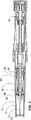
自動注射装置は2つの主要な素子、すなわち、充填された注射器50を収容する図面の左手に示すリザーバ部分と、注射器の自動的な挿入及び吐き出しを行う部品をその中に収容する図面の右手に示すパワーパックとを有する。2つの主要な素子はハウジング16とパワースリーブ1との間の銃剣式の接続を介して互いに着脱自在に接続される。次の説明において、注射針37が位置する自動注射装置の側を前部と呼ぶ。Hereinafter, exemplary embodiments of the present invention will be described in detail with reference to the accompanying drawings in an exemplary manner.
The automatic injection device has two main elements: a reservoir portion shown in the left hand of the drawing that houses the filled
作動の準備が整った自動注射装置を示す図1を参照して、パワーパックを最初に説明する。自動注射装置の推進のための部品は把持スリーブ14内に収容され、このスリーブの後端にインジケータ窓51を取り付ける。インジケータ窓51は、インジケータ窓51内に変位自在に保持されたインジケータ12を外部から観察できるように、例えば透明又は半透明な材料から作られる。インジケータ12は、使用者が薬剤の押し出し工程を目で追うことができるようにする。自動注射装置の後端に配置された作動ノブ13はその後面側にカバーディスク15を具備する。パワースリーブ1は把持スリーブ14の内部に収容される。その後端において、パワースリーブ1はスナップ接続によりキャッチスリーブ8に接続される。キャッチスリーブ8は、その一部において、その内部にバネスリーブ10を変位自在に収容する。バネスリーブ10はスナップ接続によりその後部でインジケータ12に結合される。バネスリーブ10の前側においては、伝達部分5がパワースリーブ1内に変位自在に位置する。伝達部分5は後に一層精確に説明するように注射器の内容物を押し出すために注射器50のピストンロッド52を作動させる役目を有する。バネ9が圧迫された状態でバネスリーブ10内に収容され、このバネは前部でバネスリーブ10上に支持され、後部でキャッチスリーブ8を押圧する。同様に圧迫された状態での第2のバネ11はバネスリーブ10の外部に位置し、前部で伝達部分5に接して支持され、後部でバネスリーブ10を押圧する。 The power pack will first be described with reference to FIG. 1, which shows an automatic injection device ready for operation. The parts for the propulsion of the automatic injection device are accommodated in the
ピストンガイド4と呼ばれる部品は、その前方のスリーブ形状の溝穴付き端部4´で注射器50の肩部に接して位置し、伝達部分5、バネスリーブ10及びキャッチスリーブ8を通って作動ノブ13の区域内へ延びる。ピストンガイド4はバネ7により前方へ予め圧迫されており、このバネは後部においてキャッチスリーブ8に接して支持される。その後端において、ピストンガイド4はキャッチスリーブ8上に形成された2つのキャッチローブ31により図1に示す位置に保持され、これらのローブはピストンガイド4の後端に形成された溝32に係合する。ピストンガイド4の半径方向の開口33内に収容されて伝達部分5のくぼみ34に係合する例えばボール6(図2にのみ示す)のようなキャッチ部材は、この作動位置で、伝達部分5及びピストンガイド4が一緒にのみ移動できることを保証する。ボール6の代わりに、例えばピンのような他の素子をキャッチ部材として使用することもできる。 The part called the
ここで、リザーバ部分の説明を行う。注射器50を収容するための部品は上述のようにハウジング16内に配置され、このハウジングは上述のようにパワースリーブ1に接続できる。摺動スリーブ21は針ホルダ22(図2)を介在させて注射器50をそれ自体の中に収容する。針ホルダ22は、ルーアスリップカップリングの場合に、注射器が自動注射装置内に位置する限り注射針37を注射器から引き出すことができないことを保証する。前部においては、針ホルダ22は摺動スリーブ21に接続された支持リング24に当接する。ルーア係止カップリングを有し、それ故、注射針がネジにより注射器に接続されているような注射器及び針の場合、針ホルダ22は存在しない。摺動スリーブ21はハウジング16内で変位することができ、バネ20により図1に示す作動位置へ押圧される。この目的のため、図1の作動位置においてそのほんの僅かに予め圧迫された状態で位置するバネ20は、その前部でハウジング16の円形の内側段部39に当接し、後部で摺動スリーブ21の外方へ突出する縁に当接する。スリーブ形状の針保護装置17はハウジング16内で変位できる。針保護装置17は注射針のための通路を開いた状態に維持するスナップカバー23により前部で閉じられ、その後端では内方へ向いたフランジ35を有する。バネ18は前部でスナップカバー23に当接し、後部ではキャリヤリング19に当接し、このリングは、その一部において、図1の作動位置でフランジ35に当接する。その結果、バネ18がほんの僅かに予め圧迫されているような図1の作動位置においては、このバネは効果を有しない。その理由は、その残りの予めの圧迫力が針保護装置17により吸収されるからである。注射がトリガされる前に、自動注射装置の係止を解除しなければならない。この目的のため、作動ノブ13を後部の方へ移動させる。この過程において、作動ノブ13の前縁で、インジケータ窓51の区域が開くようになり、その内側で、目立つ色で着色した警告スリーブを見ることができるようになり、この警告スリーブは、自動注射装置がこのとき係止解除され、注射の準備が整ったことを明確に示す。係止解除運動においては、作動ボタン13のカバーディスク15の内側で形成された舌片36がキャッチスリーブ上に形成されたキャッチローブ31上を摺動する。ここでは、舌片36及びキャッチローブ31は、舌片36がキャッチローブ31の端部上で摺動しながら半径方向に弾性的に降伏して、上述の溝32との係合によりピストンガイド4をしっかり保持するように、形状づけられる。係止解除運動後、作動ノブ13上に形成された舌片36はキャッチローブ31間で楔のような方法で位置する。 Here, the reservoir portion will be described. The parts for housing the
自動注射装置はこのとき注射の準備が整い、患者の皮膚上の所望の位置にスナップカバー23を置く。針保護装置17がハウジング16内で軸方向の遊びを有するので、針保護装置は皮膚に押し付けられたときに、フランジ35が段部39に当接するまで、後方へ移動する。患者は把持スリーブ14において自動注射装置を堅く握り、作動ノブ13を前方即ち患者の人体の方向へ移動させる。このトリガ運動においては、舌片36をキャッチローブ31間で押圧し、これらのローブを半径方向へ離れるように押し広げる。それによって、ピストンガイド4が解放され、バネ7の力により、前方へ推進する。密着運動はまた伝達部分5上に作用するバネ9、11の力により補助される。伝達部分5がボール6を介してピストンガイド4に接続されているので、バネ7、9、11を備え、比較的大きな始動力を有するバネ装置が提供され、このバネ装置は完全な進入深さへの注射針の信頼ある前進に貢献する。バネの力はピストンガイド4のスリーブ形状の前端4´を介して注射器50の肩部に伝達され、それを収容する摺動スリーブ21と一緒にこの肩部を前方方向へ押し、そのため、注射針が前進し、患者の皮膚に進入する。この場合、摺動スリーブ21の前端は針保護装置17内へ移動し、その設けられた可撓性の舌片38によりキャリヤリング19を一緒に運び、このようにして、バネ18を圧迫する。この挿入運動により、摺動スリーブ21はまたバネ20を圧縮する。挿入ストロークはパワースリーブ1の内側段部41に対するピストンガイド4の肩部40の当接により制限される。この端位置においては、ボール6を収容するピストンガイド4の開口33はパワースリーブ1に設けたくぼみ42に整合し、ボール6は外方へ屈することができ、ピストンガイド4と伝達部分5との間の結合がキャンセルされる。同時に、ピストンガイド4がこのときパワースリーブ1に対して係止され、そのため、バネ20の力はパワースリーブにより吸収され、バネ7の力に抵抗しない。ここで、注射が自動的に開始され、注射器50のピストンロッド52がバネ11、9の力の下に伝達部分5により前方へ更に前進させられるので、注射器50内に収容された薬剤は押し出される。図2は自動注射装置のこの作動状態を示し、この状態では、注射器50のピストンロッドの位置により図から分かるように、薬剤は完全に押し出されてしまっている。使用者はインジケータ窓51内のインジケータ12の位置によりこの状態を確認することができる。符号57で示す患者の人体組織内には注射針37がまだ刺さっている。 The automatic injection device is now ready for injection and places the
図2に示す作動位置から出発して、使用者はこのとき自動注射装置を引き戻すことができ、次いで、図3に示す作動位置に切り換わる。上述のように挿入工程中に予め圧迫されたバネ18は、針保護装置17が自動注射装置の引き戻し中に患者の皮膚に接触維持することを保証する。従って、注射針37の引き出し中、針保護装置17は、注射針37を完全に覆うまで、ハウジング及び摺動スリーブ21に対して前方へ移動する。可撓性の舌片38は針保護装置17のフランジ35の背後で外方へスナップ運動し、図3に明示するように、針保護装置17がハウジング16内へ推し戻されるのを阻止する。この手段によって、注射針によるいかなる望ましくない更なる負傷をも排除される。前部で摺動スリーブ21上に形成され、針保護装置35のフランジ35を当接させる小さなフック58(図2)は、針保護装置17が前部の方へハウジング16から脱落するのを阻止する。例えばスナップカバー23上への圧力により、針保護装置17をハウジング16内へ推し戻そうと試みても、これは、圧力が可撓性の舌片38を介して摺動スリーブ21へ伝達され、ここから注射器50へ伝達され、ここからピストンガイド4へ伝達されるという事実により、阻止される。上述のように、ピストンガイドはボール6によりパワースリーブ1に対して係止され、そのため、針保護装置17はたとえ大きな力の消費によってもハウジング16内へ押し戻すことができない。その結果、自動注射装置を取り扱う人間は首尾よく注射した後に注射針37による意図しない負傷から容易に保護される。 Starting from the operating position shown in FIG. 2, the user can now pull back the automatic injection device and then switch to the operating position shown in FIG. The
別の使用のために自動注射装置を準備するため、ハウジング16及びパワースリーブ1は銃剣式の接続を解除することにより互いに分離される。これにより、伝達部分5を介してバネ9、11により注射器50のピストンロッド52上に加えられた力及びピストンガイド4を介してバネ7により注射器50の肩部に加えられた力が排除され、そのため、挿入中に圧迫されていたバネ20は、このとき、ハウジング16に対して摺動スリーブ21をその後方の端位置の方へ押し戻す。この過程において、摺動スリーブ21はまた、針保護装置17を運ぶ。図4はこの作動位置におけるリザーバ部分を示し、この位置では、使用済みの注射器50をこのとき取り外して新たな注射器と交換できる。 To prepare the automatic injection device for another use, the
Claims (6)
Translated fromJapanese上記注射針(37)が皮膚へ進入する間、上記針保護装置(17)が上記ハウジング(16)に対して実質上一定の位置を維持し、バネ素子(18)が圧迫され、同バネ素子が、皮膚からの当該注射針(37)の取り外し後に、該針を取り囲む位置へ当該針保護装置(17)を前方に押圧すること、上記容器(50)が、上記注射針の皮膚への進入中に上記ハウジング(16)内で引き戻し位置から前進位置へ変位される摺動スリーブ(21)内に収容され、上記針保護装置(17)が係止手段(35、38)によりその前進位置において自動的に係止され、上記係止手段(35、38)は、当該針保護装置(17)及び上記摺動スリーブ(21)がその前進位置に位置するときに、当該係止手段が該針保護装置(17)と当該摺動スリーブ(17)との間で作動すること、および、上記係止手段が、上記摺動スリーブ(21)上に配置されかつ実質的に軸方向に指向した少なくとも1つの可撓性の舌片(38)を有し、同舌片が、その自由な状態において、上記針保護装置(17)の区域(35)に対する軸方向のストッパを形成することを特徴とする注射装置。An injection needle (37), a housing (16), a container (50) for the active substance, a syringe piston (52) displaceable within the container (50) to push out the active substance, and the housing Aninjection device for injecting an active substance, having a needle protection device (17) displaceable relative to the
While the injection needle (37) enters the skin, the needle protection device (17) maintains a substantially constant position with respect to the housing (16), the spring element (18) is compressed, and the spring element However, after the injection needle (37) is removed from the skin, the needle protection device (17) is pushed forward to a position surrounding the needle, and the container (50) enters the skin of the injection needle. Accommodated in a sliding sleeve (21) which is displaced in the housing (16) from the retracted position to the advanced position, and the needle protection device (17) is in its advanced position by the locking means (35, 38). The locking means (35, 38) is automatically locked when the needle protection device (17) and the sliding sleeve (21) are in their advanced positions. Protection device (17) and sliding sleeve 17) and at least one flexible tongue (38) in which the locking means are arranged on the sliding sleeve (21) and are substantially axially oriented. Aninjection device characterizedin that the tongue forms in its free state an axial stop for the area (35) of the needle protection device (17) .
Applications Claiming Priority (2)
| Application Number | Priority Date | Filing Date | Title |
|---|---|---|---|
| CH19862002 | 2002-11-25 | ||
| PCT/CH2003/000757WO2004047892A1 (en) | 2002-11-25 | 2003-11-17 | Injection apparatus comprising a needle-protecting device |
Publications (2)
| Publication Number | Publication Date |
|---|---|
| JP2006507060A JP2006507060A (en) | 2006-03-02 |
| JP4339260B2true JP4339260B2 (en) | 2009-10-07 |
Family
ID=32331828
Family Applications (1)
| Application Number | Title | Priority Date | Filing Date |
|---|---|---|---|
| JP2004554139AExpired - Fee RelatedJP4339260B2 (en) | 2002-11-25 | 2003-11-17 | Injection device with needle protection device |
Country Status (6)
| Country | Link |
|---|---|
| US (2) | US7361160B2 (en) |
| EP (1) | EP1572270A1 (en) |
| JP (1) | JP4339260B2 (en) |
| CN (1) | CN100506305C (en) |
| AU (1) | AU2003280270B2 (en) |
| WO (1) | WO2004047892A1 (en) |
Cited By (1)
| Publication number | Priority date | Publication date | Assignee | Title |
|---|---|---|---|---|
| KR101448858B1 (en) | 2014-05-15 | 2014-10-13 | 송태섭 | Capping apparatus of needle for syringe |
Families Citing this family (142)
| Publication number | Priority date | Publication date | Assignee | Title |
|---|---|---|---|---|
| WO2003068290A2 (en) | 2002-02-11 | 2003-08-21 | Antares Pharma, Inc. | Intradermal injector |
| JP4339260B2 (en)* | 2002-11-25 | 2009-10-07 | テクファーマ・ライセンシング・アクチェンゲゼルシャフト | Injection device with needle protection device |
| US20090204076A1 (en)* | 2003-02-03 | 2009-08-13 | Barry Peter Liversidge | Medical Injector |
| GB0315600D0 (en)* | 2003-07-04 | 2003-08-13 | Owen Mumford Ltd | Improvements relating to automatic injection devices |
| DE10342059B4 (en)* | 2003-09-11 | 2007-03-01 | Tecpharma Licensing Ag | Delivery device with piercing and Ausschutinrichtung |
| CH696421A5 (en)* | 2003-12-18 | 2007-06-15 | Tecpharma Licensing Ag | Autoinjector with arresting the drug container. |
| GB2414402B (en) | 2004-05-28 | 2009-04-22 | Cilag Ag Int | Injection device |
| GB2414401B (en)* | 2004-05-28 | 2009-06-17 | Cilag Ag Int | Injection device |
| GB2414398B (en)* | 2004-05-28 | 2009-04-22 | Cilag Ag Int | Injection device |
| GB2414775B (en) | 2004-05-28 | 2008-05-21 | Cilag Ag Int | Releasable coupling and injection device |
| GB2414400B (en) | 2004-05-28 | 2009-01-14 | Cilag Ag Int | Injection device |
| GB0414054D0 (en) | 2004-06-23 | 2004-07-28 | Owen Mumford Ltd | Improvements relating to automatic injection devices |
| WO2006057636A1 (en) | 2004-11-22 | 2006-06-01 | Intelliject, Llc | Devices, systems, and methods for medicament delivery |
| US10737028B2 (en) | 2004-11-22 | 2020-08-11 | Kaleo, Inc. | Devices, systems and methods for medicament delivery |
| US7648482B2 (en) | 2004-11-22 | 2010-01-19 | Intelliject, Inc. | Devices, systems, and methods for medicament delivery |
| US7648483B2 (en) | 2004-11-22 | 2010-01-19 | Intelliject, Inc. | Devices, systems and methods for medicament delivery |
| US11590286B2 (en) | 2004-11-22 | 2023-02-28 | Kaleo, Inc. | Devices, systems and methods for medicament delivery |
| US7947017B2 (en) | 2004-11-22 | 2011-05-24 | Intelliject, Inc. | Devices, systems and methods for medicament delivery |
| HUE042286T2 (en) | 2005-01-24 | 2019-06-28 | Antares Pharma Inc | Needle-filled pre-filled syringe |
| AU2006210865B2 (en) | 2005-02-01 | 2008-12-04 | Kaleo, Inc. | Devices, systems, and methods for medicament delivery |
| GB2427826B (en)* | 2005-04-06 | 2010-08-25 | Cilag Ag Int | Injection device comprising a locking mechanism associated with integrally formed biasing means |
| GB2424836B (en) | 2005-04-06 | 2010-09-22 | Cilag Ag Int | Injection device (bayonet cap removal) |
| GB2425062B (en) | 2005-04-06 | 2010-07-21 | Cilag Ag Int | Injection device |
| US20110098656A1 (en) | 2005-09-27 | 2011-04-28 | Burnell Rosie L | Auto-injection device with needle protecting cap having outer and inner sleeves |
| WO2007131025A1 (en) | 2006-05-03 | 2007-11-15 | Antares Pharma, Inc. | Injector with adjustable dosing |
| WO2007131013A1 (en) | 2006-05-03 | 2007-11-15 | Antares Pharma, Inc. | Two-stage reconstituting injector |
| GB2438591B (en) | 2006-06-01 | 2011-07-13 | Cilag Gmbh Int | Injection device |
| RU2438721C2 (en)* | 2006-06-30 | 2012-01-10 | Эбботт Байотекнолоджи Лтд. | Automatic injection device |
| KR101396797B1 (en) | 2006-06-30 | 2014-05-26 | 애브비 바이오테크놀로지 리미티드 | Automatic injection device |
| AU2007338204A1 (en)* | 2006-12-22 | 2008-07-03 | Novo Nordisk A/S | Shieldable needle assembly with biased safety shield |
| JP5362591B2 (en)* | 2007-03-09 | 2013-12-11 | イーライ リリー アンド カンパニー | Delay mechanism for automatic injection equipment |
| DE102007030327A1 (en) | 2007-06-29 | 2009-01-02 | Tecpharma Licensing Ag | Injection device with a spring for a needle protection sleeve |
| US7713243B2 (en)* | 2007-09-25 | 2010-05-11 | Becton, Dickinson And Company | Tip shield for needle stick prevention |
| EP3636301A1 (en) | 2008-03-10 | 2020-04-15 | Antares Pharma, Inc. | Injector safety device |
| US9642971B2 (en) | 2008-03-13 | 2017-05-09 | Becton, Dickinson And Company | Safety needle assembly |
| EP3527246B1 (en) | 2008-03-13 | 2022-02-16 | Becton, Dickinson and Company | Safety pen needle assembly having shield for non-patient end |
| WO2009114762A1 (en) | 2008-03-13 | 2009-09-17 | Becton, Dickinson And Company | Safety pen needle assembly having shielding for patient and non-patient ends |
| CA3070618C (en) | 2008-05-20 | 2021-07-20 | Avant Medical Corp. | Autoinjector system |
| US8177749B2 (en) | 2008-05-20 | 2012-05-15 | Avant Medical Corp. | Cassette for a hidden injection needle |
| US8052645B2 (en) | 2008-07-23 | 2011-11-08 | Avant Medical Corp. | System and method for an injection using a syringe needle |
| GB2460398A (en)* | 2008-05-20 | 2009-12-02 | Owen Mumford Ltd | Auto-injector having a magnetic injection indicator and a needle sheath retainer |
| WO2009148969A1 (en) | 2008-06-02 | 2009-12-10 | Sta-Med, Llc | Needle cover assembly for a syringe |
| GB2461085B (en) | 2008-06-19 | 2012-08-29 | Cilag Gmbh Int | Injection device |
| US8376993B2 (en) | 2008-08-05 | 2013-02-19 | Antares Pharma, Inc. | Multiple dosage injector |
| GB2463034B (en)* | 2008-08-28 | 2012-11-07 | Owen Mumford Ltd | Autoinjection devices |
| EP2326370B1 (en)* | 2008-09-18 | 2020-08-05 | Becton, Dickinson and Company | Medical injector with slidable sleeve activation |
| JP4806818B2 (en)* | 2008-11-17 | 2011-11-02 | クリエートメディック株式会社 | Trocar |
| GB0821492D0 (en)* | 2008-11-25 | 2008-12-31 | Team Holdings Uk Ltd | Integrated auto-injector cartridge system |
| GB0823693D0 (en)* | 2008-12-31 | 2009-02-04 | Owen Mumford Ltd | Autoinjector |
| KR101366427B1 (en) | 2009-03-13 | 2014-02-24 | 일라이 릴리 앤드 캄파니 | Apparatus for injecting a pharmaceutical with automatic syringe retraction following injection |
| JP5732039B2 (en) | 2009-03-20 | 2015-06-10 | アンタレス・ファーマ・インコーポレーテッド | Hazardous drug injection system |
| WO2010127146A1 (en) | 2009-04-29 | 2010-11-04 | Abbott Biotechnology Ltd | Automatic injection device |
| WO2011047298A2 (en) | 2009-10-16 | 2011-04-21 | Centocor Ortho Biotech Inc. | Palm activated drug delivery device |
| US9233213B2 (en) | 2009-10-16 | 2016-01-12 | Janssen Biotech, Inc. | Palm activated drug delivery device |
| EP2512558A4 (en) | 2009-12-15 | 2014-08-13 | Abbvie Biotechnology Ltd | IMPROVED TRIP PUSHER FOR AUTOMATIC INJECTION DEVICE |
| ES2484266T3 (en) | 2010-03-01 | 2014-08-11 | Eli Lilly And Company | Automatic injection device with delay mechanism including a double function thrust element |
| NZ702172A (en) | 2010-04-21 | 2016-03-31 | Abbvie Biotechnology Ltd | Wearable automatic injection device for controlled delivery of therapeutic agents |
| US8162882B2 (en) | 2010-06-23 | 2012-04-24 | Sta-Med, Llc | Automatic-locking safety needle covers and methods of use and manufacture |
| EP2399635A1 (en) | 2010-06-28 | 2011-12-28 | Sanofi-Aventis Deutschland GmbH | Auto-injector |
| EP2399629A1 (en)* | 2010-06-28 | 2011-12-28 | Sanofi-Aventis Deutschland GmbH | Auto-injector |
| EP2399628A1 (en)* | 2010-06-28 | 2011-12-28 | Sanofi-Aventis Deutschland GmbH | Auto-injector |
| JP6165055B2 (en)* | 2010-06-28 | 2017-07-19 | サノフィ−アベンティス・ドイチュラント・ゲゼルシャフト・ミット・ベシュレンクテル・ハフツング | Automatic syringe |
| KR101834154B1 (en) | 2010-07-02 | 2018-03-05 | 사노피-아벤티스 도이칠란트 게엠베하 | Safety device for a pre-filled syringe and injection device |
| EP2460553A1 (en)* | 2010-12-02 | 2012-06-06 | Debiotech S.A. | Device for inserting needles |
| GB201021717D0 (en) | 2010-12-22 | 2011-02-02 | Owen Mumford Ltd | Autoinjectors |
| WO2012093075A1 (en)* | 2011-01-04 | 2012-07-12 | Sanofi-Aventis Deutschland Gmbh | Safety device for a pre-filled syringe and injection device |
| RU2580982C2 (en)* | 2011-01-04 | 2016-04-10 | Санофи-Авентис Дойчланд Гмбх | Protective devices for pre-filled syringe and injection device |
| EP2661294B1 (en) | 2011-01-04 | 2020-08-26 | Sanofi-Aventis Deutschland GmbH | A safety device for a pre-filled syringe and an injection device |
| KR101989342B1 (en) | 2011-01-24 | 2019-06-14 | 애브비 바이오테크놀로지 리미티드 | Removal of needle shields from syringes and automatic injection devices |
| BR112013018905B1 (en) | 2011-01-24 | 2021-07-13 | Abbvie Biotechnology Ltd | AUTOMATIC INJECTION DEVICES THAT HAVE OVERMOLDED HANDLE SURFACES. |
| ES2710905T3 (en) | 2011-01-24 | 2019-04-29 | E3D Agricultural Coop Association Ltd | Injector |
| US8627816B2 (en) | 2011-02-28 | 2014-01-14 | Intelliject, Inc. | Medicament delivery device for administration of opioid antagonists including formulations for naloxone |
| US9173999B2 (en) | 2011-01-26 | 2015-11-03 | Kaleo, Inc. | Devices and methods for delivering medicaments from a multi-chamber container |
| US8939943B2 (en) | 2011-01-26 | 2015-01-27 | Kaleo, Inc. | Medicament delivery device for administration of opioid antagonists including formulations for naloxone |
| EP2489385A1 (en) | 2011-02-18 | 2012-08-22 | Sanofi-Aventis Deutschland GmbH | Auto-injector |
| EP2489381A1 (en) | 2011-02-18 | 2012-08-22 | Sanofi-Aventis Deutschland GmbH | Auto-injector |
| EP2489380A1 (en) | 2011-02-18 | 2012-08-22 | Sanofi-Aventis Deutschland GmbH | Injection device |
| EP2489390A1 (en) | 2011-02-18 | 2012-08-22 | Sanofi-Aventis Deutschland GmbH | Detent mechanism |
| EP2489384A1 (en) | 2011-02-18 | 2012-08-22 | Sanofi-Aventis Deutschland GmbH | Auto-injector |
| EP2489386A1 (en) | 2011-02-18 | 2012-08-22 | Sanofi-Aventis Deutschland GmbH | Auto-injector |
| EP2489389A1 (en) | 2011-02-18 | 2012-08-22 | Sanofi-Aventis Deutschland GmbH | Detent mechanism |
| EP2489382A1 (en) | 2011-02-18 | 2012-08-22 | Sanofi-Aventis Deutschland GmbH | Auto-injector |
| EP2489387A1 (en) | 2011-02-18 | 2012-08-22 | Sanofi-Aventis Deutschland GmbH | Auto-injector |
| EP2489388A1 (en) | 2011-02-18 | 2012-08-22 | Sanofi-Aventis Deutschland GmbH | Auto-injector |
| MX2013011263A (en) | 2011-03-29 | 2014-03-27 | Abbvie Inc | Improved shroud deployment in automatic injection devices. |
| PL2699293T3 (en) | 2011-04-20 | 2019-08-30 | Amgen Inc. | Autoinjector apparatus |
| WO2012166746A1 (en) | 2011-05-31 | 2012-12-06 | Sta-Med, Llc | Blood collection safety devices and methods of use and manufacture |
| US8496619B2 (en) | 2011-07-15 | 2013-07-30 | Antares Pharma, Inc. | Injection device with cammed ram assembly |
| US9220660B2 (en) | 2011-07-15 | 2015-12-29 | Antares Pharma, Inc. | Liquid-transfer adapter beveled spike |
| EP2750738B1 (en) | 2011-08-31 | 2024-05-15 | SHL Medical AG | Injection device |
| EP2572741A1 (en)* | 2011-09-23 | 2013-03-27 | Sanofi-Aventis Deutschland GmbH | Medicament delivery device and actuation mechanism for a drug delivery device |
| ES2587993T3 (en) | 2012-03-02 | 2016-10-28 | Abbvie Inc. | Automatic injection learning device |
| US9486583B2 (en) | 2012-03-06 | 2016-11-08 | Antares Pharma, Inc. | Prefilled syringe with breakaway force feature |
| EP4186545A1 (en) | 2012-04-06 | 2023-05-31 | Antares Pharma, Inc. | Needle assisted jet injection administration of testosterone compositions |
| USD808010S1 (en) | 2012-04-20 | 2018-01-16 | Amgen Inc. | Injection device |
| USD898908S1 (en) | 2012-04-20 | 2020-10-13 | Amgen Inc. | Pharmaceutical product cassette for an injection device |
| US9364610B2 (en) | 2012-05-07 | 2016-06-14 | Antares Pharma, Inc. | Injection device with cammed ram assembly |
| JP5865498B2 (en)* | 2012-07-19 | 2016-02-17 | テルモ株式会社 | Liquid dosing device |
| EP2875837B1 (en)* | 2012-07-23 | 2017-05-24 | Terumo Kabushiki Kaisha | Liquid administration tool |
| EP2727617A1 (en) | 2012-11-06 | 2014-05-07 | Sanofi-Aventis Deutschland GmbH | Autoinjector |
| US10159803B2 (en)* | 2013-02-08 | 2018-12-25 | Sanofi-Aventis Deutschland Gmbh | Drug delivery device with needle protection |
| FI3659647T3 (en) | 2013-02-11 | 2024-03-28 | Antares Pharma Inc | NEEDLE-ASSISTED SPRAY INJECTOR WITH REDUCED TRIGGER FORCE |
| CA2905031C (en) | 2013-03-11 | 2018-01-23 | Hans PFLAUMER | Dosage injector with pinion system |
| WO2014165136A1 (en) | 2013-03-12 | 2014-10-09 | Antares Pharma, Inc. | Constant volume prefilled syringes and kits thereof |
| MX2015013058A (en) | 2013-03-14 | 2016-05-31 | Lilly Co Eli | Trigger assembly for an automatic injection device. |
| KR20150119092A (en) | 2013-03-14 | 2015-10-23 | 일라이 릴리 앤드 캄파니 | Delay mechanism suitable for compact automatic injection device |
| CA2904661C (en) | 2013-03-15 | 2022-03-15 | Amgen Inc. | Drug cassette, autoinjector, and autoinjector system |
| USD731051S1 (en) | 2013-03-15 | 2015-06-02 | Janssen Biotech, Inc. | Drug delivery device |
| ES2973257T3 (en) | 2013-03-15 | 2024-06-19 | Amgen Inc | Drug cassette, autoinjector and autoinjector system |
| EP3590568A1 (en) | 2013-03-22 | 2020-01-08 | TecPharma Licensing AG | Substance dispensing device with a signalling device |
| GB2515032A (en) | 2013-06-11 | 2014-12-17 | Cilag Gmbh Int | Guide for an injection device |
| GB2515039B (en) | 2013-06-11 | 2015-05-27 | Cilag Gmbh Int | Injection Device |
| GB2517896B (en) | 2013-06-11 | 2015-07-08 | Cilag Gmbh Int | Injection device |
| GB2515038A (en) | 2013-06-11 | 2014-12-17 | Cilag Gmbh Int | Injection device |
| US10994871B2 (en)* | 2013-07-03 | 2021-05-04 | Deka Products Limited Partnership | Apparatus, system and method for fluid delivery |
| US11077965B2 (en)* | 2013-07-03 | 2021-08-03 | Deka Products Limited Partnership | Apparatus, system and method for fluid delivery |
| ES2863959T3 (en) | 2013-12-10 | 2021-10-13 | Becton Dickinson Co | Active Safety Pen Needle Assembly |
| US9623194B2 (en) | 2013-12-10 | 2017-04-18 | Becton, Dickinson And Company | Passive safety pen needle assembly |
| JP6296840B2 (en)* | 2014-03-11 | 2018-03-20 | テルモ株式会社 | Liquid dosing device |
| US9517307B2 (en) | 2014-07-18 | 2016-12-13 | Kaleo, Inc. | Devices and methods for delivering opioid antagonists including formulations for naloxone |
| CH710119A2 (en)* | 2014-09-03 | 2016-03-15 | Tecpharma Licensing Ag | An injection device with a sequencer. |
| CN104436369A (en)* | 2014-12-30 | 2015-03-25 | 江苏华阳电器有限公司 | Implicit needle mechanism of injector |
| CA2990950A1 (en) | 2015-06-30 | 2017-01-05 | Kaleo, Inc. | Auto-injectors for administration of a medicament within a prefilled syringe |
| GB2542202A (en)* | 2015-09-14 | 2017-03-15 | Consort Medical Plc | Injection device |
| GB2545266B (en) | 2015-12-11 | 2018-08-08 | Oval Medical Tech Limited | Autoinjector with retracting needle |
| WO2018119218A1 (en) | 2016-12-23 | 2018-06-28 | Kaleo, Inc. | Medicament delivery device and methods for delivering drugs to infants and children |
| CN106859811B (en)* | 2017-02-06 | 2018-05-22 | 浙江大学 | The electronic automatic acupuncture treatment device for having needle injection |
| WO2018195764A1 (en)* | 2017-04-25 | 2018-11-01 | 群康生技股份有限公司 | Injection pen |
| CN107243108B (en)* | 2017-07-03 | 2024-02-06 | 玉环天来科技有限公司 | Self-destroying sheath mechanism |
| CN109317371A (en)* | 2018-12-08 | 2019-02-12 | 大连鑫鑫创世科技发展有限公司 | Injection device and method for computer heat dissipation silicone grease heat-conducting adhesive |
| CA3145580A1 (en) | 2019-08-09 | 2021-02-18 | Kaleo, Inc. | Devices and methods for delivery of substances within a prefilled syringe |
| KR102154125B1 (en)* | 2020-03-27 | 2020-09-09 | (주)딥셀라이트 | Ampoule syringe |
| CN111939394B (en)* | 2020-08-25 | 2022-04-08 | 华中农业大学 | Syringe needle protection device |
| WO2022051176A1 (en)* | 2020-09-01 | 2022-03-10 | West Pharmaceutical Services, Inc. | Multi-stage injection device |
| US12268847B1 (en) | 2021-02-10 | 2025-04-08 | Kaleo, Inc. | Devices and methods for delivery of substances within a medicament container |
| US12343511B1 (en) | 2024-04-19 | 2025-07-01 | Genzyme Corporation | Medicament delivery device |
| US12343505B1 (en) | 2024-04-19 | 2025-07-01 | Genzyme Corporation | Medicament delivery device |
| US12377226B1 (en) | 2024-04-19 | 2025-08-05 | Genzyme Corporation | Medicament delivery device |
| US12337160B1 (en) | 2024-04-19 | 2025-06-24 | Genzyme Corporation | Medicament delivery device |
| US12357758B1 (en) | 2024-04-19 | 2025-07-15 | Genzyme Corporation | Medicament delivery device |
| US12420017B1 (en) | 2025-02-26 | 2025-09-23 | Genzyme Corporation | Damping device for a medicament delivery device |
| US12434008B1 (en) | 2025-02-26 | 2025-10-07 | Genzyme Corporation | Lock ring for a medicament delivery device |
Family Cites Families (21)
| Publication number | Priority date | Publication date | Assignee | Title |
|---|---|---|---|---|
| DE3715337C2 (en)* | 1986-11-14 | 1994-04-14 | Haselmeier Wilhelm Fa | Injection device |
| DE3638984C3 (en)* | 1986-11-14 | 1993-11-18 | Haselmeier Wilhelm Fa | Injection device |
| US5271744A (en)* | 1991-04-29 | 1993-12-21 | George C. Kramer | System and method for rapid vascular drug delivery |
| US5201708A (en)* | 1992-02-03 | 1993-04-13 | Timothy A. Kershenstine | Self-locking safety syringe |
| JP2723048B2 (en)* | 1994-06-24 | 1998-03-09 | 株式会社ニッショー | Blood suction device |
| US5658259A (en)* | 1995-10-19 | 1997-08-19 | Meridian Medical Technologies, Inc. | Dental cartridge assembly auto-injector with protective needle cover |
| US5609577A (en)* | 1996-01-29 | 1997-03-11 | Haber; Terry M. | Automatically locking hypodermic needle hiding shield for a dose metering syringe |
| US6171276B1 (en)* | 1997-08-06 | 2001-01-09 | Pharmacia & Upjohn Ab | Automated delivery device and method for its operation |
| SE9702872D0 (en)* | 1997-08-06 | 1997-08-06 | Pharmacia & Upjohn Ab | Automated delivery device and method for its operation |
| IE970782A1 (en)* | 1997-10-22 | 1999-05-05 | Elan Corp | An improved automatic syringe |
| US7029461B2 (en)* | 1999-11-04 | 2006-04-18 | Tyco Healthcare Group Lp | Safety shield for medical needles |
| FR2801795B1 (en)* | 1999-12-07 | 2002-07-05 | Plastef Investissements | SAFETY SUPPORT DEVICE FOR A SYRINGE AND ASSEMBLY OF SUCH A DEVICE AND A SYRINGE |
| SE515405C2 (en)* | 2000-01-25 | 2001-07-30 | Gudmar Olovson | Nålskyddsarrangemang |
| GB0003790D0 (en)* | 2000-02-18 | 2000-04-05 | Astrazeneca Uk Ltd | Medical device |
| US7004929B2 (en)* | 2002-03-29 | 2006-02-28 | Mdc Investment Holdings, Inc. | Safety pre-filled cartridge injector |
| AU2003275893B2 (en)* | 2002-11-25 | 2008-11-13 | Tecpharma Licensing Ag | Device for automatically injecting an active agent |
| JP4339260B2 (en)* | 2002-11-25 | 2009-10-07 | テクファーマ・ライセンシング・アクチェンゲゼルシャフト | Injection device with needle protection device |
| US6939330B1 (en)* | 2002-12-12 | 2005-09-06 | Medsolve Llc | Syringe insertion system |
| DE10339794A1 (en)* | 2003-08-28 | 2005-04-07 | Tecpharma Licensing Ag | Administering device with a protective cap removal device and a needle protection sleeve blocking device |
| CH696421A5 (en)* | 2003-12-18 | 2007-06-15 | Tecpharma Licensing Ag | Autoinjector with arresting the drug container. |
| US6989001B2 (en)* | 2004-05-28 | 2006-01-24 | Huang-Chuan Chen | Breakable syringe with a safety sleeve |
- 2003
- 2003-11-17JPJP2004554139Apatent/JP4339260B2/ennot_activeExpired - Fee Related
- 2003-11-17AUAU2003280270Apatent/AU2003280270B2/ennot_activeCeased
- 2003-11-17EPEP03770836Apatent/EP1572270A1/ennot_activeWithdrawn
- 2003-11-17WOPCT/CH2003/000757patent/WO2004047892A1/enactiveApplication Filing
- 2003-11-17CNCN200380103982.7Apatent/CN100506305C/ennot_activeExpired - Fee Related
- 2005
- 2005-05-23USUS11/135,602patent/US7361160B2/ennot_activeExpired - Fee Related
- 2007
- 2007-11-30USUS11/948,014patent/US20080071225A1/ennot_activeAbandoned
Cited By (1)
| Publication number | Priority date | Publication date | Assignee | Title |
|---|---|---|---|---|
| KR101448858B1 (en) | 2014-05-15 | 2014-10-13 | 송태섭 | Capping apparatus of needle for syringe |
Also Published As
| Publication number | Publication date |
|---|---|
| CN100506305C (en) | 2009-07-01 |
| US20080071225A1 (en) | 2008-03-20 |
| US20050273061A1 (en) | 2005-12-08 |
| AU2003280270A1 (en) | 2004-06-18 |
| WO2004047892A1 (en) | 2004-06-10 |
| US7361160B2 (en) | 2008-04-22 |
| CN1713930A (en) | 2005-12-28 |
| AU2003280270B2 (en) | 2008-01-24 |
| JP2006507060A (en) | 2006-03-02 |
| EP1572270A1 (en) | 2005-09-14 |
Similar Documents
| Publication | Publication Date | Title |
|---|---|---|
| JP4339260B2 (en) | Injection device with needle protection device | |
| US20230405235A1 (en) | Medicament delivery device | |
| US12128222B2 (en) | Safety housing based implant/medicament injecting system | |
| JP4377880B2 (en) | Device for automatically injecting medication | |
| US8062255B2 (en) | Auto-injector | |
| JP3168179B2 (en) | Injection equipment | |
| JP2006507061A (en) | Automatic injection device with resettable release safety device | |
| JP2007509658A (en) | Automatic injection device | |
| JP2007518507A (en) | Injection device | |
| EP1231963B1 (en) | Syringe of single-use type intended for injection or lab tests | |
| BG61068B1 (en) | Inoculation device |
Legal Events
| Date | Code | Title | Description |
|---|---|---|---|
| A131 | Notification of reasons for refusal | Free format text:JAPANESE INTERMEDIATE CODE: A131 Effective date:20080717 | |
| A601 | Written request for extension of time | Free format text:JAPANESE INTERMEDIATE CODE: A601 Effective date:20081017 | |
| A602 | Written permission of extension of time | Free format text:JAPANESE INTERMEDIATE CODE: A602 Effective date:20081024 | |
| A521 | Request for written amendment filed | Free format text:JAPANESE INTERMEDIATE CODE: A523 Effective date:20090115 | |
| TRDD | Decision of grant or rejection written | ||
| A01 | Written decision to grant a patent or to grant a registration (utility model) | Free format text:JAPANESE INTERMEDIATE CODE: A01 Effective date:20090602 | |
| A01 | Written decision to grant a patent or to grant a registration (utility model) | Free format text:JAPANESE INTERMEDIATE CODE: A01 | |
| A61 | First payment of annual fees (during grant procedure) | Free format text:JAPANESE INTERMEDIATE CODE: A61 Effective date:20090701 | |
| R150 | Certificate of patent or registration of utility model | Free format text:JAPANESE INTERMEDIATE CODE: R150 | |
| FPAY | Renewal fee payment (event date is renewal date of database) | Free format text:PAYMENT UNTIL: 20120710 Year of fee payment:3 | |
| LAPS | Cancellation because of no payment of annual fees |