JP4338473B2 - Endoscopic clip device - Google Patents
Endoscopic clip deviceDownload PDFInfo
- Publication number
- JP4338473B2 JP4338473B2JP2003295869AJP2003295869AJP4338473B2JP 4338473 B2JP4338473 B2JP 4338473B2JP 2003295869 AJP2003295869 AJP 2003295869AJP 2003295869 AJP2003295869 AJP 2003295869AJP 4338473 B2JP4338473 B2JP 4338473B2
- Authority
- JP
- Japan
- Prior art keywords
- clip
- string
- rear end
- pair
- clips
- Prior art date
- Legal status (The legal status is an assumption and is not a legal conclusion. Google has not performed a legal analysis and makes no representation as to the accuracy of the status listed.)
- Expired - Fee Related
Links
Images


Landscapes
- Surgical Instruments (AREA)
Description
Translated fromJapaneseこの発明は、内視鏡の処置具挿通チャンネルに通して使用されて、体内の止血、結紮或いはマーキング等を行うために用いられる内視鏡用クリップ装置に関する。 The present invention relates to an endoscope clip device that is used through a treatment instrument insertion channel of an endoscope to perform hemostasis, ligation, marking, or the like in the body.
内視鏡用クリップ装置は一般に、可撓性シース内に軸線方向に進退自在に挿通配置された操作ワイヤの先端が可撓性シースの先端部分に配置されたクリップに連結され、操作ワイヤを可撓性シースの基端側(手元側)から牽引操作することにより、クリップが嘴状に開いた状態から閉じた状態になってその状態が保持されるようになっている。 In general, the clip device for an endoscope is connected to a clip disposed at the distal end portion of the flexible sheath so that the distal end of the operation wire inserted in the flexible sheath so as to be movable forward and backward in the axial direction can be used. By pulling from the base end side (hand side) of the flexible sheath, the clip is changed from the open state to the closed state, and the state is maintained.
そのようなクリップは一般に、バネ性のある板状体を先側半部が嘴状に開いた形状に形成すると共に後側半部をループ状に形成して全体として略∝状に形成し、クリップが無負荷状態では自己の弾性によって開いていて、外套管内やクリップ閉じ筒体内に引き込まれると窄まった状態に弾性変形して閉じた状態になるようになっている(例えば、特許文献1、特許文献2)。
しかし、バネ性のある材料を∝状に正確に曲げてクリップを形成するのは部品製造コストがばかにならず、また、組み立てに際してバネ性を有する部材を窄ませる等の工程は扱い難くて非常に面倒である。また、バネがへたるとクリップの広がり方が不十分になって大きな患部のクリッピングができなくなってしまう欠点がある。 However, forming a clip by accurately bending a springy material into a bowl shape does not make the manufacturing cost of parts confusing, and the process of squeezing a springy member during assembly is difficult to handle. It is troublesome. In addition, when the spring is bent, there is a drawback that the clip does not spread sufficiently and the large affected part cannot be clipped.
そこで本発明は、部品コストが大幅に低減されて組み立ても簡単になり、さらに常に所定の状態まで開かせて大きな患部のクリッピング等でも安定して行うことができる内視鏡用クリップ装置を提供することを目的とする。 Accordingly, the present invention provides an endoscopic clip device that can greatly reduce the cost of parts, simplify assembly, and can always be opened to a predetermined state and stably performed even when clipping a large affected area. For the purpose.
上記の目的を達成するため、本発明の内視鏡用クリップ装置は、可撓性シース内に軸線方向に進退自在に挿通配置された操作ワイヤの先端が可撓性シースの先端部分に配置されたクリップに連結され、操作ワイヤを可撓性シースの基端側から牽引操作することにより、クリップが嘴状に開いた状態から閉じた状態に変化した後、操作ワイヤとクリップとの連結を外すことができるように構成された内視鏡用クリップ装置において、クリップを、外方に向かって折り曲げられた後端外折れ部が後端部に形成された一対の互いに独立した板状部材により構成して、一対のクリップの各後端外折れ部付近に形成された貫通孔に紐状体を連続して通し、紐状体を、クリップが後端側から入り込み可能な内径を有するクリップ閉じ筒体内に通して後方から牽引することにより、クリップ閉じ筒体内において一対のクリップの後端外折れ部の折れ曲がり部どうしが当接すると共にクリップ閉じ筒体の先端開口部により各クリップの広がりが規制されて、クリップが閉じた状態になるようにしたものである。 In order to achieve the above object, an endoscope clip device according to the present invention has a distal end of an operation wire, which is inserted and disposed in a flexible sheath so as to be able to advance and retreat in the axial direction, at the distal end portion of the flexible sheath. When the operating wire is pulled from the proximal end side of the flexible sheath and the clip is changed from the open state to the closed state, the connection between the operating wire and the clip is released. In the endoscope clip device configured to be capable of being configured, the clip is configured by a pair of independent plate-like members in which a rear end outer bent portion formed outward is formed at the rear end portion. Then, the string-like body is continuously passed through the through holes formed in the vicinity of the rear end outer bent portions of the pair of clips, and the string-like body is inserted into the clip closing cylinder having an inner diameter that allows the clip to enter from the rear end side. Through the body or behind By pulling, the bent portions of the rear end outer bent portions of the pair of clips are brought into contact with each other in the clip closed cylindrical body, and the spread of each clip is regulated by the front end opening of the clip closed cylindrical body, and the clip is closed. It is intended to become.
なお、一対のクリップが紐状体により後方に牽引されて後端外折れ部付近だけがクリップ閉じ筒体内に引き込まれた状態のとき、クリップが嘴状に開いた状態になるようにするとよい。 It should be noted that when the pair of clips are pulled backward by the string-like body and only the vicinity of the rear end outer bent portion is drawn into the closed-cylinder body, the clip may be opened in a hook shape.
また、紐状体がループ状に形成されていて、操作ワイヤの先端部分に側方に向けて片持ち支持された係合ピンと係合するようにしてもよい。 Further, the string-like body may be formed in a loop shape, and may be engaged with an engagement pin that is cantilevered and supported laterally at the distal end portion of the operation wire.
本発明によれば、クリップを、外方に向かって折り曲げられた後端外折れ部が後端部に形成された一対の互いに独立した板状部材により構成したので部品の製造コストが大幅に低減されると共に、一対のクリップの各後端外折れ部付近に形成された貫通孔に紐状体を連続して通せばよいので組み立ても簡単になり、後端外折れ部付近だけがクリップ閉じ筒体内に引き込まれた状態のとき一対の後端外折れ部どうしが当接してクリップが嘴状に開いた状態になるようにすることにより、クリップが常に所定の状態まで開いて大きな患部のクリッピング等でも安定して行うことができる。 According to the present invention, since the clip is composed of a pair of independent plate-like members in which a rear end outer bent portion that is bent outward is formed at the rear end portion, the manufacturing cost of the parts is greatly reduced. In addition, it is only necessary to pass the string-like body continuously through the through holes formed in the vicinity of the outer bent portions of the rear ends of the pair of clips, so that the assembly becomes easy, and only the vicinity of the outer bent portion of the rear end is closed by the clip cylinder. When the clip is pulled into the body, the pair of rear end outer folds abut each other and the clip is opened in a bowl shape, so that the clip is always opened to a predetermined state and clipping of a large affected part, etc. But it can be done stably.
クリップを、外方に向かって折り曲げられた後端外折れ部が後端部に形成された一対の互いに独立した板状部材により構成して、一対のクリップの各後端外折れ部付近に形成された貫通孔に紐状体を連続して通し、その紐状体を、クリップが後端側から入り込み可能な内径を有するクリップ閉じ筒体内に通した構成にする。 The clip is formed by a pair of independent plate-like members in which the rear end outer bent portion bent outward is formed at the rear end portion, and is formed near each rear end outer bent portion of the pair of clips. The string-like body is continuously passed through the formed through-hole, and the string-like body is passed through the clip-closed cylinder having an inner diameter that allows the clip to enter from the rear end side.
そのような紐状体を後方から牽引して、一対のクリップの後端外折れ部付近だけがクリップ閉じ筒体内に引き込まれた状態にするとクリップが嘴状に開いた状態になり、さらに紐状体を後方から牽引すると、クリップ閉じ筒体内において一対のクリップの後端外折れ部の折れ曲がり部どうしが当接すると共にクリップ閉じ筒体の先端開口部により各クリップの広がりが規制されて、クリップが閉じた状態になる。 When such a string-like body is pulled from the rear and only the vicinity of the rear end outer folding part of the pair of clips is pulled into the closed cylinder, the clip is opened in a hook-like shape, and further When the body is pulled from the rear, the bent portions of the rear end outer bent portions of the pair of clips abut each other in the clip closed cylinder, and the spread of each clip is regulated by the front end opening of the clip closed cylinder, and the clip is closed. It becomes a state.
図面を参照して本発明の実施例を説明する。
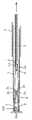
図2及び図3は内視鏡用クリップ装置の先端近傍部の側面断面図と平面断面図であり、ステンレス鋼線を一定の径で密着巻きして形成されたコイルパイプ等からなる可撓性シース1内に、軸線方向に進退自在に操作ワイヤ2が挿通配置されている。Embodiments of the present invention will be described with reference to the drawings.
2 and 3 are a side cross-sectional view and a plan cross-sectional view of the vicinity of the distal end of the clip device for an endoscope, and a flexible structure made of a coil pipe or the like formed by tightly winding a stainless steel wire with a certain diameter. An
操作ワイヤ2としては、コイルパイプ又は金属製ロープ等を用いることができ、可撓性シース1の基端に連結された操作部(図示せず)により牽引操作される。操作ワイヤ2の先端に固着されている先端チップ2aの先端部分には、操作ワイヤ2の軸線方向に直交する向きに配置された剛性の高い材料からなる係合ピン5の一端が、片持ち支持されている。 As the
可撓性シース1の先端部分には、互いに独立した一対の金属製の板片からなるクリップ3が配置されている。クリップ3は各々、ステンレス鋼板等からなる金属平板の先端部分を45°〜90°程度の角度で小さく内側に折り曲げて先端爪状部3aを形成し、後端部分を30°〜60°の角度で外方に向かって小さく折り曲げて後端外折れ部3bを形成した構成であり、極めて容易かつ安価に部品を製造することができる。なお、クリップ3にはバネ性は不要であるがバネ性を有していても差し支えない。 A
そして、各クリップ3の後端外折れ部3b(又はその近傍)に穿設された貫通孔3cに可撓性のある一本の紐状体4が連続して通され、その紐状体4は引き出された後端部どうしが結束管4aにより結束されて、全体としてループ状に形成されている。したがって、組み立ても非常に簡単で容易である。 Then, a single flexible string-
6は、クリップ3を閉じ状態に保持するための剛性材料からなる円筒状のクリップ閉じ筒体であり、その後端面は可撓性シース1の先端面に当接する径に形成され、前端の内周部分にはテーパ状に広がる面取りが形成されている。 6 is a cylindrical clip closing cylinder made of a rigid material for holding the
そのようなクリップ閉じ筒体6内に紐状体4が通されて後方に引き出され、紐状体4の後端付近の内側に係合ピン5が係合している。7は、可撓性シース1に軸線方向に進退自在に緩く被嵌された外套管である。 The string-
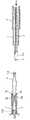
このように構成された内視鏡用クリップ装置を使用する際には、図2及び図3に示されるように、紐状体4の後端を操作ワイヤ2の先端の係合ピン5に係合させて紐状体4を可撓性シース1内に少し引き込んだら、図4に示されるように、外套管7を先側に押し出してクリップ3を囲む状態にして、図示されていない内視鏡の処置具挿通チャンネルに挿通する。 When the endoscope clip device configured as described above is used, the rear end of the string-
そして、内視鏡観察下にクリッピング対象の患部を見つけたら、図5に示されるように操作ワイヤ2を手元側から牽引して、クリップ3の後端外折れ部3bだけがクリップ閉じ筒体6内に引き込まれた状態にすることにより、各クリップ3が嘴状に開いてクリップ閉じ筒体6の先端に当接した状態になる。したがって、クリップ3を常に所定の開き角度まで確実に開かせることができる。 Then, when an affected part to be clipped is found under endoscopic observation, the
さらに、図1に示されるように、操作ワイヤ2を手元側から牽引すると後端外折れ部3bがクリップ閉じ筒体6内に引き込まれ、クリップ閉じ筒体6内において一対のクリップ3の後端外折れ部3bの基部(折り曲げ部の外周面)どうしが当接する状態になると共に、クリップ閉じ筒体6の先端開口部によって各クリップ3の広がりが規制され、次第にクリップ3が閉じて患部100を挟み付けた状態になる。 Further, as shown in FIG. 1, when the
そこで、図6の側面断面図と図7の平面断面図に示されるように、操作ワイヤ2を可撓性シース1の先端から押し出して操作ワイヤ2の先端を揺すると、その先端の係合ピン5と紐状体4との係合が外れて、クリップ3が患部100にクリッピングされて体内に留置された状態になる。 Therefore, as shown in the side sectional view of FIG. 6 and the plan sectional view of FIG. 7, when the
1 可撓性シース
2 操作ワイヤ
3 クリップ
3b 後端外折れ部
3c 貫通孔
4 紐状体
5 係合ピン
6 クリップ閉じ筒体DESCRIPTION OF SYMBOLS 1
Claims (3)
Translated fromJapanese上記クリップを、外方に向かって折り曲げられた後端外折れ部が後端部に形成された一対の互いに独立した板状部材により構成して、上記一対のクリップの各後端外折れ部付近に形成された貫通孔に上記紐状体を連続して通し、上記紐状体を、上記クリップが後端側から入り込み可能な内径を有するクリップ閉じ筒体内に通して後方から牽引することにより、上記クリップ閉じ筒体内において上記一対のクリップの後端外折れ部の折れ曲がり部どうしが当接すると共に上記クリップ閉じ筒体の先端開口部により上記各クリップの広がりが規制されて、上記クリップが閉じた状態になることを特徴とする内視鏡用クリップ装置。A distal end of an operation wire, which is inserted into the flexible sheath so as to be capable of moving forward and backward in the axial direction,is connected to a clip disposed at the distal end portion of the flexible sheathvia a string-like body, and the operation wire is connected to the movable sheath. By pulling from the proximal end side of the flexible sheath, the clip is changed from the open state to the closed state and then the connection between the operation wire and the clip can be removed. In the endoscope clip device,
The clip is composed of a pair of independent plate-like members each having a rear end folded portion bent outward and formed at the rear end portion, and near each rear end outer folded portion of the pair of clips. a through-hole formed through in successionthe cord-like body, the string-like body by the clip pulls from the rear through the clip closing cylinder body having an internal diameter capable enter from the rear side, A state in which the bent portions of the rear-end outer bent portions of the pair of clips are in contact with each other in the clip-closed cylinder, and the spread of each clip is restricted by the tip opening of the clip-close cylinder, and the clips are closed Endoscopic clip device characterized by becoming.
Priority Applications (1)
| Application Number | Priority Date | Filing Date | Title |
|---|---|---|---|
| JP2003295869AJP4338473B2 (en) | 2003-08-20 | 2003-08-20 | Endoscopic clip device |
Applications Claiming Priority (1)
| Application Number | Priority Date | Filing Date | Title |
|---|---|---|---|
| JP2003295869AJP4338473B2 (en) | 2003-08-20 | 2003-08-20 | Endoscopic clip device |
Publications (2)
| Publication Number | Publication Date |
|---|---|
| JP2005058629A JP2005058629A (en) | 2005-03-10 |
| JP4338473B2true JP4338473B2 (en) | 2009-10-07 |
Family
ID=34371951
Family Applications (1)
| Application Number | Title | Priority Date | Filing Date |
|---|---|---|---|
| JP2003295869AExpired - Fee RelatedJP4338473B2 (en) | 2003-08-20 | 2003-08-20 | Endoscopic clip device |
Country Status (1)
| Country | Link |
|---|---|
| JP (1) | JP4338473B2 (en) |
Family Cites Families (4)
| Publication number | Priority date | Publication date | Assignee | Title |
|---|---|---|---|---|
| JPS5652885Y2 (en)* | 1976-12-20 | 1981-12-10 | ||
| JP3962156B2 (en)* | 1998-04-30 | 2007-08-22 | オリンパス株式会社 | Clip molding method and clip molding apparatus |
| JP2000254143A (en)* | 1999-03-08 | 2000-09-19 | Asahi Optical Co Ltd | Endoscope hemostatic clip device |
| JP4472217B2 (en)* | 2000-10-16 | 2010-06-02 | オリンパス株式会社 | Biological tissue clip device |
- 2003
- 2003-08-20JPJP2003295869Apatent/JP4338473B2/ennot_activeExpired - Fee Related
Also Published As
| Publication number | Publication date |
|---|---|
| JP2005058629A (en) | 2005-03-10 |
Similar Documents
| Publication | Publication Date | Title |
|---|---|---|
| JP4598181B2 (en) | Endoscopic clip device | |
| JP4716513B2 (en) | Endoscopic clip device | |
| JP3776529B2 (en) | Clip device | |
| JP2008307168A (en) | Clip device for endoscope | |
| JP2008302097A (en) | Clip device for endoscope | |
| WO2016190190A1 (en) | Device for endoscope | |
| JP4261450B2 (en) | Endoscopic clip device | |
| JP4476237B2 (en) | Endoscopic clip device | |
| JP2007283015A (en) | Endoscopic clip device | |
| JP4046981B2 (en) | Endoscopic clip device | |
| JP4338473B2 (en) | Endoscopic clip device | |
| JP4491590B2 (en) | Endoscope clip | |
| JP4311953B2 (en) | Endoscopic clip device | |
| JP4575763B2 (en) | Endoscopic clip device | |
| JP4338472B2 (en) | Endoscopic clip device | |
| JP4575749B2 (en) | Endoscopic clip device | |
| JP3917466B2 (en) | Endoscopic clip device | |
| JP2002360591A (en) | Endoscope clip device | |
| JP4412943B2 (en) | Endoscopic clip device | |
| JP4095464B2 (en) | Endoscopic clip device | |
| JP2003339719A (en) | Endoscope clip device | |
| JP4261262B2 (en) | Endoscopic clip device | |
| JP2004321343A (en) | Endoscope clip device | |
| JP4338457B2 (en) | Endoscopic clip device | |
| JP3914462B2 (en) | Endoscopic clip device |
Legal Events
| Date | Code | Title | Description |
|---|---|---|---|
| A621 | Written request for application examination | Free format text:JAPANESE INTERMEDIATE CODE: A621 Effective date:20060706 | |
| A711 | Notification of change in applicant | Free format text:JAPANESE INTERMEDIATE CODE: A712 Effective date:20080501 | |
| A131 | Notification of reasons for refusal | Free format text:JAPANESE INTERMEDIATE CODE: A131 Effective date:20090108 | |
| A521 | Written amendment | Free format text:JAPANESE INTERMEDIATE CODE: A523 Effective date:20090127 | |
| TRDD | Decision of grant or rejection written | ||
| A01 | Written decision to grant a patent or to grant a registration (utility model) | Free format text:JAPANESE INTERMEDIATE CODE: A01 Effective date:20090604 | |
| A01 | Written decision to grant a patent or to grant a registration (utility model) | Free format text:JAPANESE INTERMEDIATE CODE: A01 | |
| A61 | First payment of annual fees (during grant procedure) | Free format text:JAPANESE INTERMEDIATE CODE: A61 Effective date:20090630 | |
| R150 | Certificate of patent or registration of utility model | Free format text:JAPANESE INTERMEDIATE CODE: R150 | |
| FPAY | Renewal fee payment (event date is renewal date of database) | Free format text:PAYMENT UNTIL: 20120710 Year of fee payment:3 | |
| FPAY | Renewal fee payment (event date is renewal date of database) | Free format text:PAYMENT UNTIL: 20120710 Year of fee payment:3 | |
| FPAY | Renewal fee payment (event date is renewal date of database) | Free format text:PAYMENT UNTIL: 20130710 Year of fee payment:4 | |
| LAPS | Cancellation because of no payment of annual fees |