JP4338438B2 - Endoscope gripping device - Google Patents
Endoscope gripping deviceDownload PDFInfo
- Publication number
- JP4338438B2 JP4338438B2JP2003139894AJP2003139894AJP4338438B2JP 4338438 B2JP4338438 B2JP 4338438B2JP 2003139894 AJP2003139894 AJP 2003139894AJP 2003139894 AJP2003139894 AJP 2003139894AJP 4338438 B2JP4338438 B2JP 4338438B2
- Authority
- JP
- Japan
- Prior art keywords
- guiding means
- magnetic guiding
- connector
- clip
- magnetic
- Prior art date
- Legal status (The legal status is an assumption and is not a legal conclusion. Google has not performed a legal analysis and makes no representation as to the accuracy of the status listed.)
- Expired - Fee Related
Links
Images


Landscapes
- Surgical Instruments (AREA)
- Endoscopes (AREA)
Description
Translated fromJapanese【0001】
【技術分野】
本発明は、内視鏡観察下で病変部を切除する際に、磁界によって誘導可能な磁気誘導手段を用いて、患者の病変部を把持するための内視鏡用把持装置に関する。
【0002】
【従来技術及びその問題点】
磁界によって誘導可能な磁気誘導手段(磁気アンカー)を用いて病変部を切除する際には、病変部を把持する把持部材と磁気誘導手段とを連結具で連結した内視鏡用把持装置を用いている。この装置においては、切除の状況に応じて磁気誘導手段を吸引することによって、病変部を持ち上げている。
【0003】
しかし、従来の装置では、連結具の長さを容易に調整することができないため、磁気誘導手段を徐々に高い位置に移動させていき患者の内壁にまで到達してしまうと、磁気誘導手段をそれ以上牽引することができなくなることがあった。
【0004】
【特許文献】
特願2002−268239号明細書
【0005】
【発明の目的】
そこで本発明の目的は、連結具の長さを容易に調節することができ、常に誘導手段の牽引が十分行える内視鏡用把持装置を提供することにある。
【0006】
【発明の概要】
上記問題点を解決するために、本発明の内視鏡用把持装置においては、対象物内部の対象部位を把持する把持部材と、磁性体からなり、上記対象物外部で発生した磁力によって吸引される誘導手段と、前記把持部材と前記誘導手段とを連結する連結部材と、を備え、前記誘導手段は、前記連結部材を挿入可能な貫通孔と、前記貫通孔の一方の出口に設けられ、前記連結部材を押入可能な間隙部を備える連結部材保持部と、を有することを特徴としている。
【0007】
連結部材保持部は弾性を有し、間隙部は連結部材保持部を貫通するスリットであることが好ましい。
【0008】
【発明の実施形態】
以下、本発明に係る実施形態を図面を参照しつつ詳しく説明する。本実施形態に係る内視鏡用把持装置1は、クリップ10、連結具20、磁気誘導手段30を有する。
【0009】
(1)構成
図1に示すクリップ(把持部材)10は、患者(対象物)体内の病変部(対象部位)130(図6)をつかんで持ち上げるため把持部材である。このクリップ10は、板状部材をU状に折り曲げて対とした本体部10aの先端に、間隔可変の一対の先端部10bを設けたものである。本体部10aは、その中央部に固定したラチェット部(間隔調整部)10cにより間隔を調整可能であり、ラチェット機構によって間隔調整後はその位置に固定される。ラチェット部10cは、対をなす本体部10aが間隔を縮める方向に弾性変形するときにはその変形を妨げず、かつ、間隔調整後の狭間隔に保持する機能を有する。ラチェット部10cと本体部10aのU字部分により、連結具20をクリップ10に連結するための孔部10dが形成される。なお、初期状態のクリップ10は、その弾性により、先端部10bは開いている。
【0010】
磁気誘導手段(誘導手段)30は略円筒体の強磁性体からなり、その中心に連結具20を挿通させるための貫通孔30bを備えている。貫通孔30bの一方の出口には、図2に示すような連結具保持部(連結部材保持部)30cが配置されている。連結具保持部30cは断面形状が円の弾性を有する部材(例えばゴム)であって、その中央には径方向に一部をスリット状に切り欠いて設けた連結具挿入部(間隙部)30dを備えている。連結具挿入部30d内には連結具20を押入可能であり、押入された連結具20は連結具保持部30cの弾性により連結具挿入部30dの内壁に押圧されて保持される。なお、磁気誘導手段30に用いる磁性体の例としては、純鉄、鉄合金のほか、プラチナマグネット、希土類磁石、テルビウム・ディスプロシウム・鉄合金などの磁石が挙げられる。また、連結具挿入部30dは、スリット状以外の任意の形状とすることができ、連結具保持部30cの中央以外の任意の位置に設けることができる。
【0011】
磁気誘導手段30は、患者101の体外において磁気誘導手段30を吸引制御する(磁気誘導手段30に動力を与える)磁気誘導部材112を有する磁気誘導手段誘導装置110によってその位置が制御される。磁気誘導部材112は、鉄心にコイルを巻いた構造の電磁石112cを基体112a上に配置したものである(図3)。
【0012】
磁気誘導部材112は、図3に示すように、患者101が横たわったベッド116を上から囲むようにして配置されたフレーム/レール(一平面内移動機構)114上に擦動可能に電磁石112cが患者に対向するように載置されている。このフレーム/レール114は一平面内において平行に配置されたU字状の二本のレール114a、114bからなり、ベッド116の床板116aの幅方向に平行に、二つのXYステージ(一方向移動機構)118、119の間に掛け渡されている。また、二つのXYステージ118、119は、フレーム/レール114が設けられた平面と直交する方向に相対移動可能である。以上の構成により、磁気誘導部材112は、基体112aがフレーム/レール114と擦動して二つのXYステージ118、119間を移動することができる。なお、磁気誘導部材112は、フレーム/レール114の平行な二本のレール114a、114bのうち患者101に近い側のレール114aに配置されている。
【0013】
フレーム/レール114の患者101から遠い側のレール114bには、フレーム/レール114全体の重量バランスを保つためのカウンターウエイト120がレール114b上を擦動可能に配置されている。カウンターウエイト120は、磁気誘導部材112の位置に応じて、その位置を変更する。例えば、磁気誘導部材112が患者101の正面にあるときは、カウンターウエイト120は患者101の背面に配置し、磁気誘導部材112が患者101の背面にあるときは、カウンターウエイト120は患者101の正面に配置して、フレーム/レール114全体の重量バランスをとっている。
【0014】
図1に示す連結具(連結部材)20は、クリップ10と磁気誘導手段30を連結するものであって、本体部20aの両端にはフック部20bと抜け止め部材20cとがそれぞれ設けられている。本体部20aは、剛体、弾性材料、柔軟材料のいずれでもよく、バネ、ゴム等も使用することができる。
【0015】
クリップ10と連結具20との連結は、クリップ10の孔部10dにフック部20bを掛けることによって行う。一方、連結具20と磁気誘導手段30との連結は、抜け止め部材20cを取り付けていない状態で本体部20aを貫通孔30bに挿入し、さらに連結具保持部30cに押入した後に、連結具保持部30cから突出した本体部20aの先端に抜け止め部材20cを接着固定することによって行う。
【0016】
抜け止め部材20cは、連結具保持部30c側に配置される断面が円形の基部20dと、基部20dよりも外径の大きなフランジ部20eからなり、基部20d及びフランジ部20eは連結具挿入部30dよりも十分大きな外径を有する。よって、本体部20aを磁気誘導手段30から抜く方向に引っ張っても抜け止め部材20cは連結具挿入部30d内には入れないため、連結具20が磁気誘導手段30から抜け落ちることが防止される。さらに、連結具保持部30cは弾性を有し、かつ、連結具挿入部30dは連結具20を強く押入されたときにようやく通る程度の長さに設定してあるため、押入された連結具20は連結具挿入部30dの内壁に押圧されてその位置で保持される。
なお、クリップ10と連結具20を一体で形成してもよい。
【0017】
以上のように磁気誘導部材112、XYステージ118、119、フレーム/レール114等を配置したことにより、病変部(対象部位)130切除のために最適な位置に磁気誘導部材112を配置することができる。したがって、病変部を切除しやすいように持ち上げるために、磁気誘導手段30を吸引して(動力を与えて)、連結具20を介して磁気誘導手段30に連結されたクリップ10を所望の方向に牽引することができる。
【0018】
(2)切除術実施の準備
図3に示すように、本発明に係る内視鏡用把持装置1を用いた切除術の実施に先立っては、まず、局所麻酔を施した患者101をベッド116上に横たわらせる。このときフレーム/レール114は、XYステージ118、119によって患者101の頭部101aが来る側に退避してあり、磁気誘導部材112及びカウンターウエイト120は所定の位置に配置されている。
【0019】
患者101がベッド116に横たわると、XYステージ118、119を操作することによってフレーム/レール114を患者の病変部の正面に配置し、つづいてフレーム/レール114上で擦動させることによって磁気誘導部材112を切除術開始時の位置に配置する。
【0020】
(3)クリップ10及び磁気誘導手段30の体内への導入操作(図4、図5)
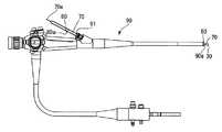
クリップ10及び磁気誘導手段30は、内視鏡90の先端硬性部60に挿通された導入管70を用いて患者(対象物)101体内に導入される。
【0021】
導入の際は、磁気誘導手段30、連結具20及びクリップ10はすでに連結されており、連結具20及びクリップ10は可撓性の中空パイプ状の導入管70内に挿入されている。磁気誘導手段30の本体部30a及び連結具保持部30cは導入管70の外部に露出している。クリップ10の先端部10bは、導入管70内において、フレキシブル・プッシング・ロッド71に当接している。71は、後端部70aが溶着されている導入管70の全長にわたって延在している。導入管70は、内視鏡90の先端90aから鉗子挿入口91までの長さより長くしてある。このため、内視鏡90の先端部90aから磁気誘導手段30の本体部30aが出た状態で導入管70を内視鏡90にセットしても、導入管70の後端部70aは鉗子挿入口91より外側に位置する。
【0022】
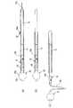
鉗子挿入口91から外に出た導入管70の後部には、切り取りひも80が設けられている。切り取りひも80は導入管70の周方向に沿って設けられ、その端部80aは作業者が切り取りひも80を引っ張りやすいように導入管70から浮いているが、端部80a以外の部分は導入管70と一体となっている。作業者が切り取りひも80を引っ張ると、切り取りひも80が導入管70の周方向に沿って取れるため、切り取りひも80が取れた部分で導入管70が前後二つに分かれる。ここで、後端部70aを引き抜くと導入管の内側に設けられたフレキシブル・プッシング・ロッド71が現れる。このフレキシブル・プッシング・ロッド71をその軸方向に移動させることにより、導入管70先端部から磁気誘導手段30、連結具20及びクリップ10が患者の体内に押し出される。
【0023】
体内に押し出されたクリップ10、連結具20及び磁気誘導手段30のうち、クリップ10は、把持鉗子100(図8、図9)により、先端部10bが開いた状態で把持されて病変部130の所定位置に配置された後、把持鉗子100によりラチェット部10cを締めることによって先端部10bが閉じられて病変部130の一部を把持した状態でその位置に固定される。このとき、磁気誘導部材112が発生する磁界は弱く設定されている。次に、磁気誘導部材112のコイルに流す電流を増やして発生する磁界を強くすることによって、磁気誘導手段30を引きつけて、病変部130を所望の高さまで引き上げる。
【0024】
以上の構成においては、磁気誘導部材112で磁気誘導手段30を吸引することにより、病変部130を十分高く持ち上げることができるため、病変部130と正常組織との境界の切除部分を十分とることができ、病変部130が扁平な形状であっても、切除部分を作りだすことができる。また、任意の位置にクリップ10を配置できるため、切除した病変部130により内視鏡の視界が妨げられることがない。
【0025】
なお、クリップ10と、連結具20及び磁気誘導手段30の連結体とは、別個に体内に導入することもできる。この場合は、これらを体内に導入した後に、把持鉗子100を用いて連結させればよい。
【0026】
(4)切除術のステップ
以上のように構成した磁気誘導手段誘導装置110を用いた病変部130の切除工程について、図6及び図7を参照しつつ説明する。
【0027】
まず、病変部130の周辺から粘膜下層(不図示)に挿入した注射針で生理食
塩水を注入して、病変部130を固有筋層(不図示)から浮き上がらせておく。
【0028】
一方、磁気誘導部材112を病変部130付近のあらかじめ設定した位置に配置する。このようにセットすると、病変部130は磁気誘導部材112と磁気誘導手段30との間の吸引力により持ち上げられる。病変部130の持ち上げ量が不足するまたは大きすぎる場合は、磁気誘導部材112の位置をずらしたり磁気誘導部材112の発生する磁界を弱めることによって調整する。
【0029】
つづいて、高周波メスなどの切開具62を鉗子チャンネル61から体内に導入し、病変部130を粘膜とともに端部から切除していく。このとき、病変部130はクリップ10により持ち上げられているため、切除部分を十分とることができ、すでに切除した病変部130が固有筋層上に落ち込むことも防ぐことができる。また、磁気誘導部材112の位置を徐々にずらすことにより切除された病変部130をさらに持ち上げることができるため、切開具62の先端位置の確認が容易となり切除作業をスムーズに行うことができる。
【0030】
切除術中においては、クリップ10を十分に牽引できない場合がある。例えば、病変部130の切除が進んで病変部130をより高く持ち上げていくと、磁気誘導手段30が患者101の内壁まで到達してしまい、それ以上クリップ10の位置を高くすることができなくなるような場合である。本実施形態においては、クリップ10と磁気誘導手段30との間隔を調整することができるため、このような場合であってもさらにクリップ10の位置を高くすることができる。
【0031】
クリップ10と磁気誘導手段30との間隔の調整は、図8及び図9に示すように、鉗子チャネル61から体内に導入した把持鉗子100によって抜け止め部材20cを把持することによって行う。先端部100aをフランジ部20eに引っ掛けることにより抜け止め部材20cを把持した状態で把持鉗子100を鉗子チャネル61内に引き戻すと、鉗子チャネル61の内径よりも外径が小さく設定されている抜け止め部材20cは鉗子チャネル61内に引き込まれるが、鉗子チャネル61の内径より外径が大きな連結具保持部30cは先端硬性部60の先端外壁60aに突き当たって鉗子チャネル61内には入らない(図8)。この状態でさらに把持鉗子100を鉗子チャネル61内に引き戻すと、連結具保持部30cは先端外壁60aに当接した状態で、本体部20aのみが鉗子チャネル61内に引き込まれる(図9)。ここで、把持鉗子100を引き戻す動きを停止すると、本体部20aは連結具保持部30cによりその位置に保持され、鉗子チャネル61内に引き込まれた分だけ磁気誘導手段30とクリップ10との間隔を短くすることができる。
【0032】
磁気誘導手段30とクリップ10とを所望の間隔に調整した後は、先端部100aを抜け止め部材20cから外し、先端硬性部60を後退させることによって抜け止め部材20cを体内に戻すことができ、切除術を再開することができる(図10)。
【0033】
状況に応じてクリップ10と磁気誘導手段30の間隔を調整しつつ切除作業を終えると、クリップ10が病変部130を把持した状態で磁気誘導手段30が磁気誘導部材112に引き寄せられるため、病変部130が紛失することを防ぐことができる。切除した病変部130を回収する場合は、磁気誘導手段30、クリップ10、連結具20及び病変部130の一部分を把持鉗子100で把持した状態で、磁気誘導部材112への電流の供給を止めて、そのまま内視鏡を抜き去ることにより回収する。その後、縫合、消毒などの処置を行う。
【0034】
なお、磁気誘導手段30は、重力を用いて牽引してもよい。
【0035】
本発明について上記実施形態を参照しつつ説明したが、本発明は上記実施形態に限定されるものではなく、改良の目的または本発明の思想の範囲内において改良または変更が可能である。
【0036】
【発明の効果】
以上説明したように、本発明によると、誘導手段に連結具を挿通できる貫通孔を設けるとともに、連結具を保持する連結具保持部材を設けることによって、連結具の長さを容易かつ任意に調節することができ、常に誘導手段の牽引が十分行える内視鏡用把持装置を提供することができる。
【図面の簡単な説明】
【図1】 本発明の実施形態に係る内視鏡用把持装置の構成を示す一部断面図である。
【図2】 (a)は本発明の実施形態に係る連結具保持部の構成を示す平面図であり、(b)は連結具保持部の連結具挿入部に連結具の本体部が押入された状態を示す平面図である。
【図3】 本発明の実施形態に係る磁気誘導手段誘導装置の構成を示す側面図である。
【図4】 本発明の実施形態に係る内視鏡の構成を示す側面図である。
【図5】 本発明の実施形態に係る内視鏡用把持装置を導入管を用いて体内に導入する過程を示した一部断面図であり、(a)は内視鏡用把持装置を導入管にセットした状態を、(b)は導入管の後端部側が除去された状態を、(c)は内視鏡用把持装置を導入管から押し出した状態を、それぞれ示している。
【図6】 本発明の実施形態に係る内視鏡用把持装置を病変部に装着した状態を示す図である。
【図7】 本発明の実施形態に係る内視鏡用把持装置により病変部を持ち上げた状態を示す図である。
【図8】 本発明の実施形態に係る内視鏡用把持装置の抜け止め部材を把持鉗子により把持した状態を示す図である。
【図9】 本発明の実施形態に係る内視鏡用把持装置の連結具を鉗子チャネル内に引き込んだ状態を示す図である。
【図10】 本発明の実施形態に係る磁気誘導手段とクリップとの間隔を調整した後の切除術の様子を示す図である。
【符号の説明】
1 内視鏡用把持装置
10 クリップ(把持部材)
20 連結具(連結部材)
30 磁気誘導手段(誘導手段)
30b 貫通孔
30c 連結具保持部(連結部材保持部)
30d 連結具挿入部(間隙部)
101 患者(対象物)
130 病変部(対象部位)[0001]
【Technical field】
The present invention relates to an endoscope gripping device for gripping a lesioned part of a patient using a magneticguiding means that can beguided by a magnetic field when the lesioned part is excised under endoscopic observation.
[0002]
[Prior art and its problems]
When excising a lesion usingmagnetic guidance means (magnetic anchor) that can beguided by amagnetic field, an endoscopic grasping device in which a grasping member for grasping the lesion and a magneticguidance means are connected by a connector is used. ing. In this apparatus, the lesioned part is lifted by attracting the magneticguiding means in accordance with the state of excision.
[0003]
However, in the conventional apparatus, since the length of the coupler cannot be easily adjusted, when the magneticguiding means is gradually moved to a higher position and reaches the inner wall of the patient, the magneticguiding means is Sometimes it was impossible to tow further.
[0004]
[Patent Literature]
Japanese Patent Application No. 2002-268239 Specification
OBJECT OF THE INVENTION
SUMMARY OF THE INVENTION An object of the present invention is to provide an endoscope gripping device that can easily adjust the length of a connector and that can always sufficiently pull theguiding means .
[0006]
Summary of the Invention
In order to solve the above-described problems, the endoscope gripping apparatus of the present invention includes a gripping member that grips a target portion inside a target object and amagnetic body, and is attracted by a magnetic force generated outside the target object. Guiding means, and a connecting member that connects the gripping member and theguiding means, and theguiding means is provided at a through hole into which the connecting member can be inserted, and at one outlet of the through hole, And a connecting member holding portion having a gap portion into which the connecting member can be pushed.
[0007]
It is preferable that the connecting member holding portion has elasticity, and the gap portion is a slit penetrating the connecting member holding portion.
[0008]
DETAILED DESCRIPTION OF THE INVENTION
Hereinafter, embodiments according to the present invention will be described in detail with reference to the drawings. Endoscopic grasping device 1 according to this embodiment, the
[0009]
(1) Configuration A clip (gripping member) 10 shown in FIG. 1 is a grasping member for grasping and lifting a lesioned part (target site) 130 (FIG. 6) in a patient (target) body. This
[0010]
The magneticinduction means (induction means ) 30 is made of a substantially cylindrical ferromagnetic body, and includes a through
[0011]
The position of the magneticguiding means 30 is controlled by a magneticguiding means guiding
[0012]
As shown in FIG. 3, the
[0013]
A
[0014]
A connecting tool (connecting member) 20 shown in FIG. 1 connects the
[0015]
The
[0016]
The retaining
Note that the
[0017]
As described above, by arranging the magnetic guiding
[0018]
(2) Preparation for Execution of Resection As shown in FIG. 3, prior to performing resection using the endoscope grasping apparatus 1 according to the present invention, first, a
[0019]
When the
[0020]
(3) Operation of introducing the
The
[0021]
At the time of introduction, the magneticguiding means 30, the
[0022]
A
[0023]
Of the
[0024]
In the above configuration, the
[0025]
In addition, the
[0026]
(4) Step of excision The excision process of the
[0027]
First, physiological saline is injected from the periphery of the
[0028]
On the other hand, the magnetic guiding
[0029]
Subsequently, an
[0030]
During resection, the
[0031]
The distance between the
[0032]
After adjusting the magneticguiding means 30 and the
[0033]
When the excision operation is completed while adjusting the distance between the
[0034]
The magneticguiding means 30 may be pulled using gravity.
[0035]
Although the present invention has been described with reference to the above embodiment, the present invention is not limited to the above embodiment, and can be improved or changed within the scope of the purpose of the improvement or the idea of the present invention.
[0036]
【The invention's effect】
As described above, according to the present invention, the adjustment provided with a through hole capable of inserting the connector intothe induction unit, by providing a connector holding member for holding the connector, the length of the coupler to easily and optionally Therefore, it is possible to provide an endoscope gripping device that can always sufficiently pull theguiding means .
[Brief description of the drawings]
FIG. 1 is a partial cross-sectional view showing a configuration of an endoscope gripping apparatus according to an embodiment of the present invention.
2A is a plan view showing a configuration of a connector holding part according to an embodiment of the present invention, and FIG. 2B is a diagram illustrating a case where the main body of the connector is pushed into the connector insertion part of the connector holding part. It is a top view which shows the state.
FIG. 3 is a side view showing the configuration of the magneticguiding means guiding device according to the embodiment of the present invention.
FIG. 4 is a side view showing the configuration of the endoscope according to the embodiment of the present invention.
FIG. 5 is a partial cross-sectional view illustrating a process of introducing the endoscope gripping apparatus according to the embodiment of the present invention into the body using an introduction tube, and (a) introduces the endoscope gripping apparatus. (B) shows a state in which the rear end side of the introduction tube is removed, and (c) shows a state in which the endoscope gripping device is pushed out from the introduction tube.
FIG. 6 is a diagram showing a state where the endoscope gripping apparatus according to the embodiment of the present invention is attached to a lesioned part.
FIG. 7 is a diagram showing a state in which a lesion is lifted by an endoscope gripping apparatus according to an embodiment of the present invention.
FIG. 8 is a view showing a state in which the retaining member of the endoscope gripping apparatus according to the embodiment of the present invention is gripped by gripping forceps.
FIG. 9 is a view showing a state in which the coupler of the endoscope gripping apparatus according to the embodiment of the present invention is pulled into the forceps channel.
FIG. 10 is a diagram showing a state of excision after adjusting the interval between the magneticguiding means and the clip according to the embodiment of the present invention.
[Explanation of symbols]
1
20 connector (connecting member)
30 Magneticguidance means (guidance means)
30b Through-
30d Connector insertion part (gap part)
101 Patient (object)
130 Lesions (target site)
Claims (2)
Translated fromJapanese磁性体からなり、上記対象物外部で発生した磁力によって吸引される誘導手段と、
前記把持部材と前記誘導手段とを連結する連結部材と、
を備え、
前記誘導手段は、前記連結部材を挿入可能な貫通孔と、
前記貫通孔の一方の出口に設けられ、前記連結部材を押入可能な間隙部を備える連結部材保持部と、
を有することを特徴とする内視鏡用把持装置。A gripping member for gripping a target part inside the target;
A guiding means made of a magnetic material and attracted by a magnetic force generated outside the object ;
A connecting member that connects the gripping member and theguiding means ;
With
Theguiding means includes a through-hole into which the connecting member can be inserted,
A connecting member holding portion provided at one outlet of the through hole, and having a gap portion into which the connecting member can be pushed,
An endoscope gripping device comprising:
Priority Applications (1)
| Application Number | Priority Date | Filing Date | Title |
|---|---|---|---|
| JP2003139894AJP4338438B2 (en) | 2003-05-19 | 2003-05-19 | Endoscope gripping device |
Applications Claiming Priority (1)
| Application Number | Priority Date | Filing Date | Title |
|---|---|---|---|
| JP2003139894AJP4338438B2 (en) | 2003-05-19 | 2003-05-19 | Endoscope gripping device |
Publications (2)
| Publication Number | Publication Date |
|---|---|
| JP2004337490A JP2004337490A (en) | 2004-12-02 |
| JP4338438B2true JP4338438B2 (en) | 2009-10-07 |
Family
ID=33528776
Family Applications (1)
| Application Number | Title | Priority Date | Filing Date |
|---|---|---|---|
| JP2003139894AExpired - Fee RelatedJP4338438B2 (en) | 2003-05-19 | 2003-05-19 | Endoscope gripping device |
Country Status (1)
| Country | Link |
|---|---|
| JP (1) | JP4338438B2 (en) |
Families Citing this family (1)
| Publication number | Priority date | Publication date | Assignee | Title |
|---|---|---|---|---|
| EP2556798A4 (en) | 2010-04-06 | 2014-09-03 | Hitachi Chemical Co Ltd | MOLDED POLYMER BODY FOR EXERCISING TRACTION ON BIOLOGICAL TISSUE, MEDICAL TRACTION MEMBER USING THE SAME, AND TRACTION TOOL FOR MEDICAL USE |
- 2003
- 2003-05-19JPJP2003139894Apatent/JP4338438B2/ennot_activeExpired - Fee Related
Also Published As
| Publication number | Publication date |
|---|---|
| JP2004337490A (en) | 2004-12-02 |
Similar Documents
| Publication | Publication Date | Title |
|---|---|---|
| JP4147315B2 (en) | Magnetic anchor remote guidance system | |
| JP4338440B2 (en) | Magnetic guidance means guidance system for endoscope | |
| JP4320214B2 (en) | Endoscopic grasping device and magnetic anchor remote guidance system | |
| JP4338438B2 (en) | Endoscope gripping device | |
| JP4373715B2 (en) | Endoscopic grasping device and anchor remote guidance system | |
| JP4320212B2 (en) | Endoscope gripping device | |
| JP4373720B2 (en) | Endoscope anchor remote guidance system | |
| JP4349850B2 (en) | Endoscope anchor remote guidance system | |
| JP4338437B2 (en) | Endoscope guidance means remote guidance system | |
| JP4320202B2 (en) | Endoscope anchor remote guidance system and endoscope guidance device | |
| JP4360838B2 (en) | Endoscope anchor remote guidance system | |
| JP4349847B2 (en) | Endoscopic magnetic anchor remote guidance system | |
| JP4338420B2 (en) | Endoscope gripping device | |
| JP4338443B2 (en) | Endoscope gripping device | |
| JP4360835B2 (en) | Endoscopic grasping device and magnetic anchor remote guidance system | |
| JP4373714B2 (en) | Endoscope gripping device | |
| JP4320201B2 (en) | Endoscope gravity guidance device | |
| JP2004344488A (en) | Endoscope anchor guidance system and endoscope treatment method using anchor guidance system | |
| JP2004321315A (en) | Endoscope anchor guidance system and endoscope treatment method using anchor guidance system | |
| JP2004358024A (en) | Endoscope anchor remote guidance system and endoscope treatment method using anchor remote guidance system | |
| JP4243977B2 (en) | Endoscope anchor guidance system | |
| JP4462482B2 (en) | Magnetic anchor remote guidance system | |
| JP2004358136A (en) | Endoscope anchor remote guidance system and endoscope treatment method using anchor remote guidance system | |
| JP2005319274A (en) | Endoscopic grasping device and magnetic anchor remote guidance system | |
| JP2004321692A (en) | Magnetic anchor remote guidance system with gravity direction visual recognition device and endoscope treatment method using magnetic anchor remote guidance system with gravity direction visualization device |
Legal Events
| Date | Code | Title | Description |
|---|---|---|---|
| A621 | Written request for application examination | Free format text:JAPANESE INTERMEDIATE CODE: A621 Effective date:20060327 | |
| RD04 | Notification of resignation of power of attorney | Free format text:JAPANESE INTERMEDIATE CODE: A7424 Effective date:20070625 | |
| A711 | Notification of change in applicant | Free format text:JAPANESE INTERMEDIATE CODE: A712 Effective date:20080501 | |
| A131 | Notification of reasons for refusal | Free format text:JAPANESE INTERMEDIATE CODE: A131 Effective date:20090407 | |
| A521 | Written amendment | Free format text:JAPANESE INTERMEDIATE CODE: A523 Effective date:20090507 | |
| TRDD | Decision of grant or rejection written | ||
| A01 | Written decision to grant a patent or to grant a registration (utility model) | Free format text:JAPANESE INTERMEDIATE CODE: A01 Effective date:20090602 | |
| A01 | Written decision to grant a patent or to grant a registration (utility model) | Free format text:JAPANESE INTERMEDIATE CODE: A01 | |
| A61 | First payment of annual fees (during grant procedure) | Free format text:JAPANESE INTERMEDIATE CODE: A61 Effective date:20090630 | |
| R150 | Certificate of patent or registration of utility model | Free format text:JAPANESE INTERMEDIATE CODE: R150 | |
| FPAY | Renewal fee payment (event date is renewal date of database) | Free format text:PAYMENT UNTIL: 20120710 Year of fee payment:3 | |
| FPAY | Renewal fee payment (event date is renewal date of database) | Free format text:PAYMENT UNTIL: 20120710 Year of fee payment:3 | |
| S111 | Request for change of ownership or part of ownership | Free format text:JAPANESE INTERMEDIATE CODE: R313115 | |
| FPAY | Renewal fee payment (event date is renewal date of database) | Free format text:PAYMENT UNTIL: 20120710 Year of fee payment:3 | |
| R350 | Written notification of registration of transfer | Free format text:JAPANESE INTERMEDIATE CODE: R350 | |
| LAPS | Cancellation because of no payment of annual fees |