JP4338027B2 - Portable terminal device and display control method thereof - Google Patents
Portable terminal device and display control method thereofDownload PDFInfo
- Publication number
- JP4338027B2 JP4338027B2JP2004020229AJP2004020229AJP4338027B2JP 4338027 B2JP4338027 B2JP 4338027B2JP 2004020229 AJP2004020229 AJP 2004020229AJP 2004020229 AJP2004020229 AJP 2004020229AJP 4338027 B2JP4338027 B2JP 4338027B2
- Authority
- JP
- Japan
- Prior art keywords
- display
- pattern
- state
- unit
- self
- Prior art date
- Legal status (The legal status is an assumption and is not a legal conclusion. Google has not performed a legal analysis and makes no representation as to the accuracy of the status listed.)
- Expired - Fee Related
Links
Images


Classifications
- Y—GENERAL TAGGING OF NEW TECHNOLOGICAL DEVELOPMENTS; GENERAL TAGGING OF CROSS-SECTIONAL TECHNOLOGIES SPANNING OVER SEVERAL SECTIONS OF THE IPC; TECHNICAL SUBJECTS COVERED BY FORMER USPC CROSS-REFERENCE ART COLLECTIONS [XRACs] AND DIGESTS
- Y02—TECHNOLOGIES OR APPLICATIONS FOR MITIGATION OR ADAPTATION AGAINST CLIMATE CHANGE
- Y02D—CLIMATE CHANGE MITIGATION TECHNOLOGIES IN INFORMATION AND COMMUNICATION TECHNOLOGIES [ICT], I.E. INFORMATION AND COMMUNICATION TECHNOLOGIES AIMING AT THE REDUCTION OF THEIR OWN ENERGY USE
- Y02D30/00—Reducing energy consumption in communication networks
- Y02D30/70—Reducing energy consumption in communication networks in wireless communication networks
Landscapes
- Mobile Radio Communication Systems (AREA)
- Telephone Function (AREA)
Description
Translated fromJapanese本発明は、携帯電話機等の携帯端末装置およびその表示制御方法に係り、特に、表示部の低消費電力を考慮したモードを有する携帯端末装置およびその表示制御方法に関するものである。 The present invention relates to a mobile terminal device such as a mobile phone and a display control method thereof, and more particularly, to a mobile terminal device having a mode in consideration of low power consumption of a display unit and a display control method thereof.
待機時の消費電力を抑えるために、表示部および/またはキー操作部の低消費電力を考慮した低消費電力モードに遷移する携帯電話機等の携帯端末装置が知られている(たとえば特許文献1参照)。 In order to reduce power consumption during standby, a portable terminal device such as a mobile phone that shifts to a low power consumption mode considering low power consumption of a display unit and / or a key operation unit is known (see, for example, Patent Document 1). ).
特許文献1に記載されている携帯端末装置は、電池を電源として液晶等の表示部およびキー操作部を持つ携帯電話機である。
この携帯電話機は、電池残量を複数のレベルに区分してレベル値を割り付けた第1テーブルと、このレベル値に対応させてタイマカウント値を割りつけた第2テーブルと、このタイマカウント値に到達するまでの間、制御部によりバックラインを点灯させるものである。
具体的には、キー操作部でキー押下があったときの電池残量のレベル値を第1レベルを参照して判定し、レベル値が所定レベル値を超えているときには、バックラインを点灯させるとともに、第1および第2テーブルを参照して設定すべきタイマカウント値を読み出して制御部に設定する。The mobile terminal device described in
The cellular phone includes a first table in which the remaining battery level is divided into a plurality of levels and assigned level values, a second table in which timer count values are assigned in correspondence with the level values, and the timer count values. Until it reaches, the back line is turned on by the control unit.
Specifically, the level value of the remaining battery level when the key is pressed on the key operation unit is determined with reference to the first level, and when the level value exceeds a predetermined level value, the back line is turned on. At the same time, the timer count value to be set is read with reference to the first and second tables and set in the control unit.
この携帯電話機によれば、特別に部品を追加することなく、またユーザが特に操作をすることなく自動的にバックライトを減光するか、あるいは最後のキー押下後短時間でバックラインとを消灯することから、電池の消費電力を効率的に抑制することができるという利点がある。
ところで、近年、メインの表示部の他に、LCD(Liquid Crystal Display)や有機EL(ElectroLuminescent)ディスプレイのサブ表示部が、開閉自在な筐体が閉状態にあっても露出する位置に配置されている携帯電話機が提案され、実用に供されている。
そして、2つの表示部を有する携帯電話機における低消費電力化が望まれている。
特に、自発光型の有機ELディスプレイをサブ表示部に採用した場合、液晶と比べてEL自体が発光するために消費電力が増加することから、さらに効率的な消費電力化が必要となる。
また、有機ELには寿命があるため、発光時間をできるだけ短時間とする必要がある。By the way, in recent years, in addition to the main display unit, a sub display unit of an LCD (Liquid Crystal Display) or an organic EL (Electro Luminescent) display has been arranged at a position where it can be exposed even when the openable / closable housing is in a closed state. Mobile phones have been proposed and put into practical use.
A reduction in power consumption in a mobile phone having two display portions is desired.
In particular, when a self-luminous organic EL display is adopted as the sub display unit, the EL itself emits light as compared with the liquid crystal, so that the power consumption increases, and thus more efficient power consumption is required.
Moreover, since organic EL has a lifetime, it is necessary to make the light emission time as short as possible.
しかしながら、特許文献1を含む従来の携帯電話機では、表示素子の寿命を考慮した表示制御についてはなんら考慮されていないのが現状である。 However, the conventional mobile phone including
また、サブ表示部を設けた携帯電話機の場合、操作性等を考慮して、筐体が閉状態にあっても露出する位置に配置されている表示部と同一の筐体のである背面(露出面)に、表示部の表示状態を指示するために押下キー(スイッチ)が配置される。
この場合、背面にスイッチが配置されているために、たとえば鞄の中に閉状態で入れておいた場合等に、勝手にスイッチが押されてしまう可能性があり、その分無駄な電力を消費してしまう。Further, in the case of a mobile phone provided with a sub display unit, in consideration of operability and the like, the back surface (exposed) of the same casing as the display unit disposed at the position where the casing is exposed even when the casing is in the closed state A pressing key (switch) is arranged on the screen) to instruct the display state of the display unit.
In this case, since the switch is arranged on the back, the switch may be pushed without permission, for example, when it is put in a closed state in a bag, which consumes unnecessary power. Resulting in.
しかしながら、上述した特許文献1を含む従来の携帯電話機では、このようなスイッチの誤操作に対する対策は行っておらず、背面に表示部およびスイッチを設けた構成とした場合であっても、意図しないスイッチの操作により無駄な電力を消費するおそれが大きい。 However, in the conventional mobile phone including the above-described
本発明は、かかる事情に鑑みてなされたものであり、その目的は、低消費電力に対応した効率の良い表示制御を行うことができ、また表示指定のための入力部の誤操作があったとしても無駄な電力の消費を防止することが可能な携帯端末装置およびその表示制御方法を提供することにある。 The present invention has been made in view of such circumstances, and its purpose is that it is possible to perform efficient display control corresponding to low power consumption, and there is an erroneous operation of an input unit for display designation. It is another object of the present invention to provide a portable terminal device capable of preventing wasteful power consumption and a display control method thereof.
上記目的を達成するため、本発明の第1の観点は、複数の表示項目を表示可能な自発光表示部と、上記自発光表示部における表示状態を指定可能な入力部と、少なくとも上記表示項目のうち、複数の項目を表示する第1のパターンと、上記第1のパターンとは異なる項目を表示する第2のパターンとをもって上記自発光表示部に表示可能で、上記入力部が短押下されるごとに、上記自発光表示部の状態を上記第1のパターン、第2のパターン、および表示項目を表示しない表示無しの状態の第3のパターンをもって巡回的に遷移させる制御部と、を有し、上記制御部は、上記第1のパターンまたは第2のパターンをもって上記自発光表示部への表示を行っている場合、それぞれ第1のパターンまたは第2のパターンの表示状態となってから所定時間の経過により強制的に表示無しの状態に遷移させ、上記自発光表示部が表示無しの状態のときに上記入力部が短押下された際、当該表示無しの状態が上記所定時間の経過に基づいて強制的に表示無しの状態に遷移されたものである場合には表示無しの状態を維持し、当該表示無しの状態が上記第3のパターンへの遷移指示に基づいたものである場合には上記第1のパターンへと表示を遷移させ、上記自発光表示部が表示無しの状態のときに上記入力部が長押下された際、上記自発光表示部の状態を上記第1のパターンに遷移させる。
好適には、上記第1のパターンは、第1項目と第2項目とを含む複数の項目を表示し、上記第2のパターンは、上記表示項目のうち、上記第1項目を含み上記第2項目を含まない表示を行うパターンであり、上記制御部は、上記入力部の短押下により、上記第1のパターンから第2のパターンに遷移される場合において、上記第1項目の表示位置が維持される。
また、好適には、上記第1項目は自装置の状態の表示であり、上記第2項目は時刻あるいはカレンダーでの表示である。In order to achieve the above object, a first aspect of the present invention is a self-luminous display unit capable of displaying a plurality of display items, an input unit capable of designating a display state in the self-luminous display unit, and at least the display item The first pattern for displaying a plurality of items and the second patternfor displaying items different from the first patterncan be displayed on the self-luminous display unit, and the input unit can be pressed shortly. A control unit that cyclically transitions the state of the self-light-emitting display unit with the first pattern, the second pattern, and the third pattern without display that does not display display items. When the control unit performs display on the self-luminous display unit with the first pattern or the second pattern, the control unit performs the operation after the display state of the first pattern or the second pattern respectively. Forcibly transitioned to the state without the display over time,when the input section in the state without displaying the above self-luminous display unit is short depressed, the state of the display without the over the predetermined time In the case where the state is forcibly transitioned to the state without display based on the state, the state without display is maintained, and the state without display is based on the transition instruction to the third pattern Transitions the display to the first pattern, and when the input unit is pressed for a long time when the self-luminous display unit is in a non-display state, the state of the self-luminous display unit is changed to the first pattern. Transition.
Preferably, the first pattern displays a plurality of items including a first item and a second item, and the second pattern includes the first item and the second item among the display items. The display unit does not include an item, and the control unit maintains the display position of the first item when the input unit is briefly pressed to transition from the first pattern to the second pattern. Is done.
Preferably, the first item is a display of the status of the device itself, and the second item is a time or calendar display.
好適には、上記入力部は、第1の入力パターンおよび第2の入力パターンをもって上記表示部における表示状態を指定可能で、上記制御部は、上記入力部が上記第1の入力パターンをもって操作されるごとに、上記表示部の状態を上記第1のパターン、第2のパターン、および第3のパターンをもって巡回的に遷移させ、第1のパターン、第2のパターン、または第3のパターンの表示状態となってから所定時間の経過により強制的に表示無しの状態に遷移させた場合、上記入力部が第2の入力パターンをもって操作されると、上記表示部の状態を上記第1のパターンに遷移させる。 Preferably, the input unit can specify a display state on the display unit with a first input pattern and a second input pattern, and the control unit is operated with the first input pattern on the input unit. Each time, the state of the display unit is cyclically changed with the first pattern, the second pattern, and the third pattern, and the first pattern, the second pattern, or the third pattern is displayed. In the case where the state is forcibly shifted to a state without display after a predetermined time has elapsed since the state is reached, when the input unit is operated with the second input pattern, the state of the display unit is changed to the first pattern. Transition.
好適には、第1の筐体と第2の筐体が開閉自在に構成され、上記表示部および入力部は、上記第1の筐体と第2の筐体が閉状態にあっても露出する位置に配置されている。 Preferably, the first casing and the second casing are configured to be openable and closable, and the display unit and the input unit are exposed even when the first casing and the second casing are in a closed state. It is arranged at the position to do.
好適には、第1の筐体と第2の筐体が開閉自在に構成され、上記表示部および入力部は、上記第1の筐体と第2の筐体が閉状態にあっても露出する位置に配置され、上記制御部は、上記強制的に表示無しの状態に遷移させた後、上記第1の筐体と第2の筐体の閉状態の発生が新たに検出されると上記表示部の状態を上記第1のパターンに遷移させる。Preferably, the first casing and the second casing are configured to be openable and closable, and the display unit and the input unit are exposed even when the first casing and the second casing are in a closed state. is disposed at a position, wherein the control unit,after transition to state withoutthe forced display,the occurrence of the closedstate of the first casing and the second casingis newly detected above The state of the display unit is changed to the first pattern.
好適には、上記入力部は、キーの押下操作により表示部における表示状態を指定可能である。 Preferably, the input unit can designate a display state on the display unit by pressing a key.
好適には、上記入力部はキーの押下操作により表示部における表示状態を指定可能であり、上記第1の入力パターンおよび第2の入力パターンは、キーの押下時間が異なり、第2の入力パターンにおけるキーの押下時間は、上記第1の入力パターンのキーの押下時間により長く設定されている。 Preferably, the input unit can specify a display state on the display unit by a key pressing operation, and the first input pattern and the second input pattern have different key pressing times, and the second input pattern The key pressing time is set to be longer than the key pressing time of the first input pattern.
本発明の第2の観点は、自発光表示部に複数の表示項目を表示する携帯端末装置の表示制御方法であって、
少なくとも上記表示項目のうち、複数の項目を表示する第1のパターンと、上記第1のパターンとは異なる項目を表示する第2のパターンとをもって上記自発光表示部に表示させるステップと、
所定のキーが短押下されるごとに、上記自発光表示部の状態を上記第1のパターン、第2のパターン、および表示項目を表示しない表示無しの状態の第3のパターンをもって巡回的に遷移させるステップと、
上記第1のパターンまたは第2のパターンをもって上記自発光表示部への表示を行っている場合、それぞれ第1のパターンまたは第2のパターンの表示状態となってから所定時間の経過により強制的に表示無しの状態に遷移させるステップと、
上記自発光表示部が表示無しの状態のときに上記所定のキーが短押下された際、
当該表示無しの状態が上記所定時間の経過に基づいて強制的に表示無しの状態に遷移されたものである場合には表示無しの状態を維持し、当該表示無しの状態が上記第3のパターンへの遷移指示に基づいたものである場合には上記第1のパターンへと表示を遷移させるステップと、
上記自発光表示部が表示無し状態のときに上記所定のキーが長押下された際、上記自発光表示部の状態を上記第1のパターンに遷移させるステップと、を有する。
A second aspect of the present invention is a display control method for a mobile terminal device that displays a plurality of display items on a self-luminous display unit,
Displaying on the self-luminous display unit with at least a first pattern for displaying a plurality of items among the display items and a second pattern for displaying items different from the first pattern;
Each time a predetermined key is pressed for a short time, the state of the self-luminous display section is cyclically changed with the first pattern, the second pattern, and the third pattern in which no display item is displayed. Step to
When the display on the self-luminous display unit is performed with the first pattern or the second pattern, the display is forcibly performed after a predetermined time from the display state of the first pattern or the second pattern. A transition to a non-display state;
When the predetermined key is pressed for a short time when the self-luminous display portion is in a state of no display,
When the state without display is a state in which the state without display is forcibly transitioned to the state without display based on the passage of the predetermined time, the state without display is maintained, and the state without display is the third pattern. If the display is based on a transition instruction to, a step of transitioning the display to the first pattern,
Transitioning the state of the self-luminous display section to the first pattern when the predetermined key is pressed for a long time when the self-luminous display section is in a no-display state.
好適には、上記第1ステップにおける所定の条件が、キーの長押しである。 Preferably, the predetermined condition in the first step is a long key press.
好適には、上記第1ステップにおける所定の条件が、筐体の閉動作である。 Preferably, the predetermined condition in the first step is a closing operation of the housing.
また、好適には、上記表示有り状態、または上記表示有り状態からキー操作により上記表示無し状態に遷移させた状態において、所定時間経過するとフラグ無しにする第4ステップをさらに有する。 Preferably, there is further provided a fourth step of setting no flag when a predetermined time elapses in the state with the display or the state with the display and the state without the display by the key operation.
本発明によれば、低消費電力に対応した効率の良い表示制御を行うことができる。
また、表示指定のための入力部の誤操作があったとしても無駄な電力の消費を防止することができる利点がある。According to the present invention, efficient display control corresponding to low power consumption can be performed.
Further, there is an advantage that wasteful power consumption can be prevented even if there is an erroneous operation of the input unit for designating the display.
以下、本発明の実施形態を添付図面に関連付けて説明する。 Hereinafter, embodiments of the present invention will be described with reference to the accompanying drawings.
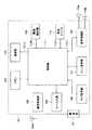
図1は、発明に係る携帯端末装置の表示制御方法を採用した携帯電話機の一実施形態を示すシステム構成図である。
また、図2は、本実施形態に係る携帯電話機の開状態における外観の一例を示す斜視図であり、図3は、本実施形態に係る携帯電話機の閉状態における外観の一例を示す斜視図である。FIG. 1 is a system configuration diagram showing an embodiment of a mobile phone employing a display control method for a mobile terminal device according to the invention.
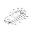
FIG. 2 is a perspective view showing an example of the appearance of the mobile phone according to the present embodiment in the open state, and FIG. 3 is a perspective view showing an example of the appearance of the mobile phone according to the present embodiment in the closed state. is there.
本実施形態に係る携帯電話機100は、図1に示すように、電池からなる電源部101、送受信アンテナ102aを含む通信処理部102、メモリ103、キー入力部104、撮像部105、開閉検知部106、メイン表示部107、スピーカ108aおよびマイクロフォン108bとを含む音声処理部108、サブ表示部109、入力部としての背面キー110、および制御部111を有している。 As shown in FIG. 1, the
図2および図3に示すように、携帯電話機100は、第1の筐体112と第2の筐体113とが、ヒンジを含む可動機構部114により開閉自在に構成されている。
第1の筐体112は、可動機構部114の近傍に送受信アンテナ102aが配置され、その正面側112aには、図2に示すように、キー入力部104と、マイクロフォン108bと、開閉検知部106の第1スイッチ部106aが配置されている。マイクロフォン108bはキー入力部104の下部に配置され、第1スイッチ部106aはキー入力部104の図中右側上部に配置されている。As shown in FIGS. 2 and 3, in the
The
第2の筐体113の正面側113aには、図2に示すように、メイン表示部107と、スピーカ108aと、開閉検知部106の第1スイッチ部106aと閉状態時に対向する第2スイッチ部106bが配置されている。スピーカ108aはメイン表示部107の上部に配置され、第2スイッチ部106bはメイン表示部107の右側下部に配置されている。
第2の筐体113の背面側114aには、図3に示すように、ハーフミラー115が配置され、そのハーフミラー115内にサブ表示部109が配置され、サブ表示部109の近傍にプッシュスイッチからなる背面キー110が配置され、また可動機構部114の近傍に、撮像部105の対物レンズを含む光学系105a、およびフラッシュランプ105bが配置されている。On the
As shown in FIG. 3, a
このように、サブ表示部109および背面キー110は、第1の筐体112と第2の筐体113が開状態、閉状態にかかわらず、露出する位置である携帯電話機100の第2の筐体113の背面側113aに配置されている。 As described above, the
電源部101は、電池を含み、図1に示す各構成部に所定の駆動電力を供給する。
また、電源部101から供給される電力は、構成部に応じて制御部111によって制御される。たとえばメイン表示部107やサブ表示部109の表示状態に応じて制御部111によって電力供給が制御される。The
Further, the power supplied from the
通信処理部102は、電波を利用した無線通信を行うために、制御部111で処理された画像データ、音声情報、電子メール等の各種情報を変調して送受信アンテナ102aを通して図示しない基地局を含む通信網に送信する。
また、通信処理部102は、管理センタから通信網を介して送信されてくる画像データ、音声情報、電子メール等を送受信アンテナ102aを通して受信し、受信した各種情報を復調して制御部111に出力する。The
The
メモリ103は、EEPROM等の不揮発性メモリを含み、たとえば撮像部105により撮影され、圧縮された画像データを格納する。 The
キー入力部114は、終了(終話)/電源キー、開始(発呼)キー、数字等に対応した複数のテンキー等を有し、これらのキーが操作されることにより、ユーザからの入力情報を制御部111に供給する。 The
撮像部105は、被写体像を取り込むための対物レンズを含む光学系105aと、光学系により結像された被写体の像を電気信号に変換する撮像素子を含む撮像処理回路とを有する。
撮像部105は、制御部111により第1の制御信号CTL1を受けて撮影動作を行う。The
The
撮像部105の光学系105aは、たとえば図3に示すように、ユーザから見て相手側が撮影できるように、携帯電話機100の第2の筐体113の背面側に配置され、撮像処理回路の撮像素子の受光面上に被写体の光学像を結像する。
撮像部105による撮像は、たとえばキー入力部104に配置され、撮像キーとして割り当てられた所定のキー操作により開始される。このとき、撮像部105は、たとえば制御部111の制御に従って、撮像時にフラッシュランプ105bを点灯させる。For example, as shown in FIG. 3, the
Imaging by the
撮像処理回路は、光学系により結像された被写体の光学像を電気信号に変換する。
具体的には、撮像処理回路において、被写体の像は、撮像素子の2次元平面上に画素単位で配置される複数の受光素子により受光される。その際、受光素子上のカラーフィルタを通して、色の情報を光3原色(R,G,B)に分解して取り込む。
そして、撮像処理回路は、各画素の輝度値が電圧に変換し、順にアナログ/デジタル(A/D)変換器によってデジタルデータに変換して、制御部111に供給する。
なお、撮像素子としては、たとえばCCDやCMOSセンサが適用される。The imaging processing circuit converts an optical image of a subject formed by the optical system into an electric signal.
Specifically, in the imaging processing circuit, an image of a subject is received by a plurality of light receiving elements arranged in units of pixels on a two-dimensional plane of the imaging element. At that time, the color information is separated into the three primary colors (R, G, B) through the color filter on the light receiving element.
Then, the imaging processing circuit converts the luminance value of each pixel into a voltage, sequentially converts it into digital data by an analog / digital (A / D) converter, and supplies the digital data to the
As the image sensor, for example, a CCD or a CMOS sensor is applied.
開閉検知部106は、第1の筐体112と第2の筐体113が開状態にあるか閉状態にあるかを検知し、検知結果を検知信号S106として制御部111に出力する。 The open /
メイン表示部107は、液晶表示装置(LCD)や有機EL等の表示デバイスを有し、通話機能のために入力した電話番号や各種メッセージ、テキストデータ等を表示する。
また、撮影モードにおいて、撮像部115により得られた被写体の画像がメイン表示部107に表示される。
メイン表示部107は、開閉検知部106の検知信号S106が、第1の筐体112と第2の筐体113が開状態にある旨を示しているときに、制御部111により点灯するように制御される。The
In the shooting mode, the subject image obtained by the
The
音声処理部108は、音声処理回路を有し、通話機能のために音声出力を行うスピーカ108aと、音声入力を行うマイクロフォン108bとが接続されている。
音声処理部108は、無線通信モードにおいて、マイクロフォン108bにより収音した音声に対して所定の処理を行って制御部111に出力する。
音声処理部108は、制御部111により供給された音声情報に対して所定の処理を行ってスピーカ108aから放音させる。The
The
The
サブ表示部109は、たとえば有機ELディスプレイデバイスにより構成され、第2の筐体113の背面側113aに内蔵するように設けられている。
なお、有機ELディスプレイとは、電気光学素子としての有機EL素子がマトリクス状に配列され、この有機EL素子が自発光して可視状態となるため、バックライトを必要とせず、低消費電力デバイスとして用いられているが、表示されている面積分の発光がなされることもあり、表示させる面積が少ない方が消費電力は低下するという特徴を持つ。The
In addition, the organic EL display is an organic EL element as an electro-optical element arranged in a matrix, and the organic EL element emits light and becomes visible, so that a backlight is not required and the device is a low power consumption device. Although it is used, light emission corresponding to the displayed area may be performed, and power consumption decreases when the display area is smaller.
サブ表示部109は、制御部111の制御に従って、複数の表示項目を表示可能である。サブ表示部109は、表示項目の全てを表示する第1のパターンと、表示項目の一部を表示する第2のパターンと、表示項目を表示しない表示無しの状態の第3のパターンを、背面キー110が押下されるごとに巡回的に切り替えて表示する。
サブ表示部109に表示される第1のパターンには、時刻を表示する時刻表示領域や日時を表すカレンダー表示領域と、携帯電話機100の状態表示領域とを全表示領域を使用して表示する図4中Aで示すパターンが含まれる。
また、第2のパターンとしては、Aにて示されていた各表示領域のうち最も面積の大きい時計表示領域を消灯するとともに、カレンダーで使用していたカレンダー表示領域をカレンダーに代えて携帯電話機100の設定状況に変更し、携帯電話機100の状態表示領域については表示を継続させるという、部分的に不使用な領域を設ける図4中Bで示すようパターンが含まれる。さらに、第2のパターンには、図4のパターンBからさらにカレンダー表示領域についても消灯し、携帯電話機100の状態表示領域については表示を継続させるという、部分的に不使用な領域を拡大した図4中Cで示すようなパターンも含まれる。
第3のパターンとしては、図4のパターンCからさらに携帯電話機100の状態表示領域についても消灯して全ての表示領域を消灯する図4中Dで示すようなパターンが含まれる。The
In the first pattern displayed on the
Further, as the second pattern, the clock display area having the largest area among the display areas indicated by A is turned off, and the calendar display area used in the calendar is replaced with the calendar and the
The third pattern includes a pattern as indicated by D in FIG. 4 in which the state display area of the
サブ表示部109の表示は、背面キー110が押下されるごとに切り替わるが、図4中、A〜Dに示すパターンを表示している場合に、所定時間、たとえば10秒間背面キー110が押下(操作)されない場合には、制御部111の制御の下、タイムアウトとして強制的に消灯(表示無しの状態に遷移)される。
サブ表示部109は、タイムアウトとして強制的に消灯(表示無しの状態に遷移)された後に、たとえば開閉検知部106の検知信号S106を新たに検出したときに第1パターンをもって表示するように点灯制御される。なお、第1の筐体112と第2の筐体113とが閉状態のときに、サブ表示部109がタイムアウトして強制的に消灯された場合には、一旦開状態にした後、再び閉状態になされると、新たに検知信号S106の入力を検知できるため、サブ表示部109は第1のパターンをもって表示するように点灯制御される。The display of the
The
背面キー110は、制御部111により入力の有効無効が制御され、有効として制御されているとき、キーの押下操作により図4に示すようなサブ表示部109における表示状態(表示パターン)を指定可能である。
背面キー110は、第1の入力パターンおよび第2の入力パターンにより入力することが可能である。
第1の入力パターンは、キーの押下操作により図4に示すようなサブ表示部109における表示状態を指定する入力パターンであり、通常のキー押下(短時間の押下)により表示パターンを指定する。
第2の入力パターンは、第1の入力パターンによりキー押下時間が長い入力パターンであり、たとえば背面キー110を長く押下(たとえば2秒以上)する入力パターンでる。
背面キー110を長く押下すると、制御部111がキーフラグをセットして背面キー110の入力を有効とする。
また、タイムアウトによりサブ表示部109に表示していた第1のパターン、第2のパターン、または第3のパターンの表示状態となってから強制的に消灯(表示無しの状態)に遷移させた場合に、背面キー110を長押しすると、サブ表示部109には制御部111に制御に従って、第1のパターン、すなわち、図4中Aで示すような、時刻や日時を示すカレンダー表示と携帯電話機100の状態表示とを含むパターンをもって表示するように点灯制御される。The
The
The first input pattern is an input pattern for designating a display state in the
The second input pattern is an input pattern in which the key pressing time is long according to the first input pattern, for example, an input pattern in which the
When the
In addition, when the display state of the first pattern, the second pattern, or the third pattern displayed on the
制御部111は、マイクロコンピュータを主体として構成され、携帯電話機100の全体の制御を行う。
たとえば、制御部111は、通信処理部102における各種情報の無線による送受信の制御、第2の制御信号CTL2による撮像部105の撮影制御、第1の制御信号CTL1による音声処理部108に対する音声情報の処理、メイン表示部107への情報の表示および点灯制御、サブ表示部109への点灯表示制御、キー入力部104の入力情報に応じた処理、メモリ103に対するアクセス制御等を行う。The
For example, the
制御部111は、たとえば開閉検知部106の検知信号S106が、第1の筐体112と第2の筐体113が開状態にある旨を示しているときに無線通信モードとなって、メイン表示部107の点灯および表示制御を行う。このとき、制御部111は、サブ表示部109を消灯状態に制御する。
無線通信モードは、通信処理部102を通して無線通信が可能なモードであり、制御部111は、表示部117に電源起動直後の標準画面(いわゆる待ち受け画面)を表示させる。無線通信モードにおいては、キー入力部104の操作により発呼動作等を行うことが可能である。For example, when the detection signal S106 of the open /
The wireless communication mode is a mode in which wireless communication is possible through the
制御部111は、背面キー110が長押下されずキーフラグをセットしていない場合には、サブ表示部109を消灯状態に制御し、また、背面キー110の入力を受け付けない。
制御部111は、背面キー110が長押下されると、キーフラグをセットして、サブ表示部109が点灯するように制御し、まず、サブ表示部109に第1のパターン(図4のAのパターンをもって表示するように制御し、キーフラグがセットされている間は、背面キー110の入力を有効であるとして受け付ける。When the
When the
制御部111は、キーフラグがセットされている状態で、背面キー110の第1のパターンの表示から10秒以内に背面キー110が押下されると、第2のパターン(図4のBのパターン)の表示に切り替え、第2のパターンを表示するために背面キー110が押下されてから10秒以内に背面キー110が押下されると他の第2のパターン(図4のCのパターン)の表示に切り替え、第2のパターンを表示するために背面キー110が押下されてから10秒以内に背面キー110が押下されると第3のパターン(図4のDのパターン)の表示に切り替え、第3のパターンを表示するために背面キー110が押下されてから10秒以内に背面キー110が押下されると第1のパターン(図4のAのパターン)の表示に切り替える。
すなわち、制御部111は、キーフラグがセットされていて、サブ表示部109に第1のパターンを表示した後に、10秒以内に背面キー110が押下されると、図4に示すA〜Dの4つのパターンを巡回的に表示させる。When the
That is, when the key flag is set and the
制御部111は、キーフラグがセットされていて、背面キー110が押下されるごとにサブ表示部109に図4中、A〜Dに示す各パターンを表示している場合に、所定時間、たとえば10秒間以上、背面キー110が押下(操作)されない場合には、タイムアウトとしてキーフラグをリセットして強制的に消灯(表示無しの状態に遷移)させる。
制御部111は、このようにサブ表示部109をタイムアウトとして強制的に消灯(表示無しの状態に遷移)させた後に、たとえば第1の筐体112と第2の筐体113が閉状態にある旨を示す開閉検知部106の検知信号S106を入力したときには、キーフラグをセットして第1のパターンをもって表示するように点灯制御する。
すなわち、制御部111は、無線通信モードの処理を終了し、第1の筐体112と第2の筐体113があわさるように閉状態とされると、キーフラグをセットして、サブ表示部109にカレンダー表示を含む第1のパターンをもって表示させる。When the key flag is set and each pattern shown in FIG. 4A to FIG. 4D is displayed on the
After the
That is, when the
次に、本実施形態に係る携帯電話機の動作を、図4、および図5のフローチャートに関連付けて、サブ表示部および背面キーの制御を中心に説明する。 Next, the operation of the mobile phone according to the present embodiment will be described with reference to the flowcharts of FIGS. 4 and 5, focusing on the control of the sub display unit and the back key.
ユーザが通話あるいはメール転送を行おうとして、閉状態にある第1の筐体112と第2の筐体113を開状態とすると、開閉検知部106から検知信号S106が入力されないため、第1の筐体112と第2の筐体113が開状態にあると、制御部111により判定される。
これにより、制御部111は、無線通信モードとなって、メイン表示部107の点灯および表示制御を行う。このとき、制御部111は、サブ表示部109を消灯状態に制御する。
無線通信モードにおいて、制御部111は、表示部117に電源起動直後の標準画面(いわゆる待ち受け画面)を表示させる、そして、ユーザのキー入力部104の操作により発呼動作等が行われる。If the user opens the
Accordingly, the
In the wireless communication mode, the
ユーザが所望する処理を終了し、開状態にある第1の筐体112と第2の筐体113を閉状態とすると、開閉検知部106から第1の筐体112と第2の筐体113が閉状態になった旨を示す検知信号S106が、制御部111に入力される。
検知信号S106を受けた制御部111は、無線通信モードの処理を終了し、第1の筐体112と第2の筐体113があわさるように閉状態とされたものとして、まず、キーフラグをセットして、サブ表示部109にカレンダー表示を含む第1のパターンをもって表示させる。
このときユーザが、背面キー110を操作することなく、携帯電話機100を鞄やポケットにしまった場合には、背面キー110が第1の入力パターンをもって10秒以上押下(操作)されないことから、制御部111は、タイムアウトとして、キーフラグをリセットしてサブ表示部109を消灯状態に遷移させる。When the processing desired by the user is finished and the
The
At this time, if the user puts the
ここで、ユーザが鞄やポケットから携帯電話機100を取り出し、サブ表示部109の表示を確認する場合には、まず、サブ表示部109が表示無し状態(消灯状態)に制御されていることから(ST1)、背面キー110を長押下する。
背面キー110が長押下されたことから、制御部111は、キーフラグをセットする。そして、キーフラグがセットされている状態で、背面キー110の図4の第1のパターンの表示から10秒以内に背面キー110が押下されると、制御部111は、図4Bのパターンの表示に切り替える。
同様に、図4Bのパターンを表示するために背面キー110が押下されてから10秒以内に背面キー110が押下されると図4Cのパターンの表示に切り替え、図4Cのパターンを表示するために背面キー110が押下されてから10秒以内に背面キー110が押下されると図4Dのパターンの表示に切り替え、図4Dのパターンを表示するために背面キー110が押下されてから10秒以内に背面キー110が押下されると図4Aのパターンの表示に切り替える(ST3,ST4)。Here, when the user takes out the
Since the
Similarly, when the
制御部111は、キーフラグがセットされていて、背面キー110が押下されるごとにサブ表示部109に図4中、A〜Dに示す各パターンを表示している場合に、10秒間以上、背面キー110が押下(操作)されない場合には、タイムアウトとしてキーフラグをリセットして強制的に消灯(表示無しの状態に遷移)させる(ST5)。 When the key flag is set and each pattern shown in FIGS. 4A to 4D is displayed on the
このように、本実施形態においては、第1の筐体112と第2の筐体113が閉状態とされると、キーフラグをセットしてサブ表示部109を一旦所定のパターンで表示させるものの、10秒以上、サブ表示部109に所定のパターンを表示を指定する背面キー110の操作がないと強制的にキーフラグをリセットしてタイムアウトとしてキーフラグをリセットして強制的に消灯(表示無しの状態に遷移)させることから、低消費電力に対応した効率の良い表示制御を行うことができ、また発光時間を短くできる利点がある。
また、たとえば鞄の中に閉状態で入れておいた場合等に、勝手にスイッチが押されてしまったとしても、10秒以上、背面キー110の操作がないと強制的にキーフラグをリセットしてタイムアウトとしてキーフラグをリセットして強制的に消灯させ、長押下または新たに検知信号S106を検出しない限り表示無しの状態を維持することから、その分無駄な電力を消費することもなく、無駄な発光時間を短くすることができる。
特に、自発光型の有機ELディスプレイをサブ表示部に採用した場合、液晶と比べてEL自体が発光するために消費電力が増加することから、本発明を適用することにより、さらに効率的な消費電力化が実現できる。
また、有機ELには寿命があるが、発光時間をできるだけ短時間とすることができることから、表示素子の寿命を延ばすことが可能となる。As described above, in the present embodiment, when the
For example, even if the switch is pushed without permission when it is put in the bag in a closed state, the key flag is forcibly reset if the
In particular, when a self-light-emitting organic EL display is used for the sub display unit, the EL itself emits light compared to the liquid crystal, which increases power consumption. Electricity can be realized.
Moreover, although organic EL has a lifetime, since the light emission time can be as short as possible, the lifetime of the display element can be extended.
100…携帯電話機、101…電源部、102…通信処理部、103…メモリ、104…キー入力部、105…撮像部、106…開閉検知部、107…メイン表示部、108…音声処理部、109…サブ表示部、110…背面キー、111…制御部。
DESCRIPTION OF
Claims (5)
Translated fromJapanese上記自発光表示部における表示状態を指定可能な入力部と、
少なくとも上記表示項目のうち、複数の項目を表示する第1のパターンと、上記第1のパターンとは異なる項目を表示する第2のパターンとをもって上記自発光表示部に表示可能で、上記入力部が短押下されるごとに、上記自発光表示部の状態を上記第1のパターン、第2のパターン、および表示項目を表示しない表示無しの状態の第3のパターンをもって巡回的に遷移させる制御部と、を有し、
上記制御部は、
上記第1のパターンまたは第2のパターンをもって上記自発光表示部への表示を行っている場合、それぞれ第1のパターンまたは第2のパターンの表示状態となってから所定時間の経過により強制的に表示無しの状態に遷移させ、
上記自発光表示部が表示無しの状態のときに上記入力部が短押下された際、
当該表示無しの状態が上記所定時間の経過に基づいて強制的に表示無しの状態に遷移されたものである場合には表示無しの状態を維持し、当該表示無しの状態が上記第3のパターンへの遷移指示に基づいたものである場合には上記第1のパターンへと表示を遷移させ、
上記自発光表示部が表示無しの状態のときに上記入力部が長押下された際、
上記自発光表示部の状態を上記第1のパターンに遷移させる
ことを特徴とする携帯端末装置。A self-luminous display that can display multiple display items;
An input unit capable of designating a display state in the self-luminous display unit;
Among the display items, at least a first pattern for displaying a plurality of items and a second patternfor displaying items different from the first patterncan be displayed on the self-luminous display unit, and the input unit A control unit that cyclically transitions the state of the self-luminous display unit with the first pattern, the second pattern, and the third pattern without display that does not display the display item each time the button is pressed for a short time And having
The control unit
When the display on the self-luminous display unit is performed with the first pattern or the second pattern, the display is forcibly performed after a predetermined time from the display state of the first pattern or the second pattern. Transition to the no display state,
When the input unit is pressed for a short time when the self-luminous display unit is in a non-display state,
When the state without display is a state in which the state without display is forcibly transitioned to the state without display based on the passage of the predetermined time, the state without display is maintained, and the state without display is the third pattern. If it is based on a transition instruction to, the display transitions to the first pattern,
When the input unit is pressed for a long time when the self-luminous display unit is not displayed,
The state of theupper Symbol self-luminous display unit portable terminal apparatus characterized by transitioning to the first pattern.
上記第2のパターンは、上記表示項目のうち、上記第1項目を含み上記第2項目を含まない表示を行うパターンであり、
上記制御部は、上記入力部の短押下により、上記第1のパターンから第2のパターンに遷移される場合において、上記第1項目の表示位置が維持される
ことを特徴とする請求項1に記載の携帯端末装置。The first pattern displays a plurality of items including a first item and a second item,
The second pattern is a pattern in which the display includes the first item and does not include the second item among the display items.
2. The control unit according to claim 1, wherein the display position of the first item is maintained when the control unit is transitioned from the first pattern to the second pattern by a short press of the input unit. The portable terminal device described.
ことを特徴とする請求項2に記載の携帯端末装置。The portable terminal device according to claim 2, wherein the first item is a display of the state of the device itself, and the second item is a time or calendar display.
上記表示部および入力部は、上記第1の筺体と第2の筺体が閉状態にあっても露出する位置に配置され、
上記制御部は、
上記強制的に表示無しの状態に遷移させた後、上記第1の筺体と第2の筺体の閉状態の発生が新たに検出されると上記表示部の状態を上記第1のパターンに遷移させる
ことを特徴とする請求項1に記載の携帯端末装置。The first housing and the second housing are configured to be openable and closable,
The display unit and the input unit are arranged at positions that are exposed even when the first casing and the second casing are in a closed state,
The control unit
After the forced transition to the non-display state, when the occurrence of the closed state of the first casing and the second casing is newly detected, the state of the display unit is transitioned to the first pattern. The mobile terminal device according to claim 1.
少なくとも上記表示項目のうち、複数の項目を表示する第1のパターンと、上記第1のパターンとは異なる項目を表示する第2のパターンとをもって上記自発光表示部に表示させるステップと、
所定のキーが短押下されるごとに、上記自発光表示部の状態を上記第1のパターン、第2のパターン、および表示項目を表示しない表示無しの状態の第3のパターンをもって巡回的に遷移させるステップと、
上記第1のパターンまたは第2のパターンをもって上記自発光表示部への表示を行っている場合、それぞれ第1のパターンまたは第2のパターンの表示状態となってから所定時間の経過により強制的に表示無しの状態に遷移させるステップと、
上記自発光表示部が表示無しの状態のときに上記所定のキーが短押下された際、
当該表示無しの状態が上記所定時間の経過に基づいて強制的に表示無しの状態に遷移されたものである場合には表示無しの状態を維持し、当該表示無しの状態が上記第3のパターンへの遷移指示に基づいたものである場合には上記第1のパターンへと表示を遷移させるステップと、
上記自発光表示部が表示無し状態のときに上記所定のキーが長押下された際、上記自発光表示部の状態を上記第1のパターンに遷移させるステップと、を有する
ことを特徴とする携帯端末装置の表示制御方法。A display control method for a mobile terminal device that displays a plurality of display items on a self-luminous display unit,
Displaying on the self-luminous display unit with at least a first pattern for displaying a plurality of items among the display items and a second pattern for displaying items different from the first pattern;
Each time a predetermined key is pressed for a short time, the state of the self-luminous display section is cyclically changed with the first pattern, the second pattern, and the third pattern in which no display item is displayed. Step to
When the display on the self-luminous display unit is performed with the first pattern or the second pattern, the display is forcibly performed after a predetermined time from the display state of the first pattern or the second pattern. A transition to a non-display state;
When the predetermined key is pressed for a short time when the self-luminous display portion is in a state of no display,
When the state without display is a state in which the state without display is forcibly transitioned to the state without display based on the passage of the predetermined time, the state without display is maintained, and the state without display is the third pattern. If the display is based on a transition instruction to, a step of transitioning the display to the first pattern,
A step of transitioning the state of the self-luminous display unit to the first pattern when the predetermined key is pressed for a long time when the self-luminous display unit is in a no-display state. A display control method for a terminal device.
Priority Applications (1)
| Application Number | Priority Date | Filing Date | Title |
|---|---|---|---|
| JP2004020229AJP4338027B2 (en) | 2004-01-28 | 2004-01-28 | Portable terminal device and display control method thereof |
Applications Claiming Priority (1)
| Application Number | Priority Date | Filing Date | Title |
|---|---|---|---|
| JP2004020229AJP4338027B2 (en) | 2004-01-28 | 2004-01-28 | Portable terminal device and display control method thereof |
Related Child Applications (1)
| Application Number | Title | Priority Date | Filing Date |
|---|---|---|---|
| JP2008167960ADivisionJP4514815B2 (en) | 2008-06-26 | 2008-06-26 | Portable electronic device and display control method thereof |
Publications (2)
| Publication Number | Publication Date |
|---|---|
| JP2005217641A JP2005217641A (en) | 2005-08-11 |
| JP4338027B2true JP4338027B2 (en) | 2009-09-30 |
Family
ID=34904204
Family Applications (1)
| Application Number | Title | Priority Date | Filing Date |
|---|---|---|---|
| JP2004020229AExpired - Fee RelatedJP4338027B2 (en) | 2004-01-28 | 2004-01-28 | Portable terminal device and display control method thereof |
Country Status (1)
| Country | Link |
|---|---|
| JP (1) | JP4338027B2 (en) |
Families Citing this family (1)
| Publication number | Priority date | Publication date | Assignee | Title |
|---|---|---|---|---|
| JP2009272996A (en)* | 2008-05-09 | 2009-11-19 | Toshiba Corp | Mobile terminal |
- 2004
- 2004-01-28JPJP2004020229Apatent/JP4338027B2/ennot_activeExpired - Fee Related
Also Published As
| Publication number | Publication date |
|---|---|
| JP2005217641A (en) | 2005-08-11 |
Similar Documents
| Publication | Publication Date | Title |
|---|---|---|
| EP1303113B1 (en) | Portable terminal | |
| US20040082367A1 (en) | Electronic apparatus | |
| US7880686B2 (en) | Mobile device | |
| JP5211793B2 (en) | Mobile phone | |
| JP2010041518A (en) | Cellular phone with key backlight and information notification method employing key backlight | |
| JP2005309751A (en) | Electronic device, power saving control method for electronic device, and recording medium on which program for executing the method is recorded | |
| JP4338027B2 (en) | Portable terminal device and display control method thereof | |
| JP4514815B2 (en) | Portable electronic device and display control method thereof | |
| US20080088553A1 (en) | Portable apparatus | |
| JP2004104245A (en) | Mobile terminal device | |
| JP4637961B2 (en) | Mobile terminal device | |
| JP3842673B2 (en) | Communication terminal | |
| JP2007005915A (en) | Mobile terminal device | |
| JP3975351B2 (en) | Portable information terminal device | |
| JP2006280011A (en) | Portable device | |
| KR200272803Y1 (en) | Cellular Phone Having Camera and Flash | |
| JP2004153756A (en) | Portable equipment | |
| JP2007150549A (en) | TERMINAL DISPLAYING OPERATING STATUS AND TERMINAL OPERATING STATUS DISPLAY DEVICE | |
| JP2007259470A (en) | Portable device | |
| JP4336361B2 (en) | Mobile device | |
| KR20030054947A (en) | Equipment attached flash of a portable telephone having a photographic function | |
| JP3896121B2 (en) | Portable terminal device and backlight control method thereof | |
| JP3877515B2 (en) | Mobile phone | |
| JP3564349B2 (en) | LCD and LED lighting time variable system and method for mobile phone | |
| JP2006311608A (en) | Portable device |
Legal Events
| Date | Code | Title | Description |
|---|---|---|---|
| A621 | Written request for application examination | Free format text:JAPANESE INTERMEDIATE CODE: A621 Effective date:20070119 | |
| A977 | Report on retrieval | Free format text:JAPANESE INTERMEDIATE CODE: A971007 Effective date:20080421 | |
| A131 | Notification of reasons for refusal | Free format text:JAPANESE INTERMEDIATE CODE: A131 Effective date:20080430 | |
| A521 | Request for written amendment filed | Free format text:JAPANESE INTERMEDIATE CODE: A523 Effective date:20080630 | |
| A131 | Notification of reasons for refusal | Free format text:JAPANESE INTERMEDIATE CODE: A131 Effective date:20090224 | |
| A521 | Request for written amendment filed | Free format text:JAPANESE INTERMEDIATE CODE: A523 Effective date:20090427 | |
| TRDD | Decision of grant or rejection written | ||
| A01 | Written decision to grant a patent or to grant a registration (utility model) | Free format text:JAPANESE INTERMEDIATE CODE: A01 Effective date:20090526 | |
| A01 | Written decision to grant a patent or to grant a registration (utility model) | Free format text:JAPANESE INTERMEDIATE CODE: A01 | |
| A61 | First payment of annual fees (during grant procedure) | Free format text:JAPANESE INTERMEDIATE CODE: A61 Effective date:20090624 | |
| R150 | Certificate of patent or registration of utility model | Ref document number:4338027 Country of ref document:JP Free format text:JAPANESE INTERMEDIATE CODE: R150 Free format text:JAPANESE INTERMEDIATE CODE: R150 | |
| FPAY | Renewal fee payment (event date is renewal date of database) | Free format text:PAYMENT UNTIL: 20120710 Year of fee payment:3 | |
| FPAY | Renewal fee payment (event date is renewal date of database) | Free format text:PAYMENT UNTIL: 20130710 Year of fee payment:4 | |
| LAPS | Cancellation because of no payment of annual fees |