JP4336023B2 - Implant screw - Google Patents
Implant screwDownload PDFInfo
- Publication number
- JP4336023B2 JP4336023B2JP2000136109AJP2000136109AJP4336023B2JP 4336023 B2JP4336023 B2JP 4336023B2JP 2000136109 AJP2000136109 AJP 2000136109AJP 2000136109 AJP2000136109 AJP 2000136109AJP 4336023 B2JP4336023 B2JP 4336023B2
- Authority
- JP
- Japan
- Prior art keywords
- screw
- thread
- implant
- base
- inner screw
- Prior art date
- Legal status (The legal status is an assumption and is not a legal conclusion. Google has not performed a legal analysis and makes no representation as to the accuracy of the status listed.)
- Expired - Lifetime
Links
- QWILCUQKBQYMTQ-UHFFFAOYSA-NCCC1CC(CN)CC1Chemical compoundCCC1CC(CN)CC1QWILCUQKBQYMTQ-UHFFFAOYSA-N0.000description1
Images


Classifications
- A—HUMAN NECESSITIES
- A61—MEDICAL OR VETERINARY SCIENCE; HYGIENE
- A61B—DIAGNOSIS; SURGERY; IDENTIFICATION
- A61B17/00—Surgical instruments, devices or methods
- A61B17/56—Surgical instruments or methods for treatment of bones or joints; Devices specially adapted therefor
- A61B17/58—Surgical instruments or methods for treatment of bones or joints; Devices specially adapted therefor for osteosynthesis, e.g. bone plates, screws or setting implements
- A61B17/68—Internal fixation devices, including fasteners and spinal fixators, even if a part thereof projects from the skin
- A61B17/74—Devices for the head or neck or trochanter of the femur
- A61B17/742—Devices for the head or neck or trochanter of the femur having one or more longitudinal elements oriented along or parallel to the axis of the neck
Landscapes
- Health & Medical Sciences (AREA)
- Orthopedic Medicine & Surgery (AREA)
- Surgery (AREA)
- Life Sciences & Earth Sciences (AREA)
- Heart & Thoracic Surgery (AREA)
- Nuclear Medicine, Radiotherapy & Molecular Imaging (AREA)
- Engineering & Computer Science (AREA)
- Biomedical Technology (AREA)
- Neurology (AREA)
- Medical Informatics (AREA)
- Molecular Biology (AREA)
- Animal Behavior & Ethology (AREA)
- General Health & Medical Sciences (AREA)
- Public Health (AREA)
- Veterinary Medicine (AREA)
- Surgical Instruments (AREA)
- Prostheses (AREA)
Description
Translated fromJapanese【0001】
【発明の属する技術分野】
本発明は、骨接合術に用いる骨接合材料に関し、特に、骨の海綿骨に挿入し、骨折部に圧迫力を与えるインプラントスクリューに関する。
【0002】
【従来の技術】
骨折した患部における骨接合術では、例えば大腿骨頸部や転子部のような一方の骨(大きな遠位骨片)と、骨頭や、骨頭を含む転子部のような他方の骨(近位骨片)にわたり、インプラントスクリューを挿入して、適切な整復位に固定させ、骨折部における骨癒合を促す。
【0003】
従来は、先端にネジ山を備える内スクリューと、該内スクリューが挿通可能な貫通孔を有し、外周にネジ山を備え、同軸状に配置させる外スクリューとからなるインプラントスクリューが提案された。内スクリューにはドライバー用の溝またはレンチ用の角穴を設け、外スクリューにはボックスレンチ用の頭部を設け、それぞれの回転操作を可能とする。
【0004】
該インプラントスクリューの設置方法は、以下のようになる。
【0005】
一方の骨の皮質から、該骨の海綿骨の途中まで、外スクリューを挿入する穴を設ける。該穴の底面に、骨折部を貫通するように、内スクリューを挿入する穴をさらに設ける。穴の縁には、外スクリューのネジ山に合わせたタッピンッグを施し、穴の先端には、内スクリューのネジ山に合わせたタッピングを施す。
【0006】
次に、内スクリューを穴に差し込み、ドライバーなどで回転させて、先端側の骨の皮質近くまで挿入する。そして、外スクリューを、内スクリューと同軸状にに被せ穴に差し込み、ボックスレンチなどで回転させて、穴から頭部が突出した状態で留める。すなわち、内スクリューと外スクリューとは同軸状に配置されるが、相互に固定されることはなく、骨折部がずれないようにだけしている。
【0007】
このようなインプラントスクリューを、1本から3本程挿入して、骨折部がずれないように固定する。そして、数か月から数年経過観察した後、骨癒合を確認してから、様子を判断して必要であれば、インプラントスクリューはすべて抜き取る。
【0008】
該インプラントスクリューを使用すると、荷重や、行動、動作により、骨折部を圧迫するように荷重がかかり、骨折部の骨癒合が促される。これは、骨折部に圧迫刺激が加わることにより、骨形成が促されることが知られているので、前記荷重を圧迫刺激として利用している。しかし、内スクリューと外スクリューの2本を順次挿入するために、手数のかかること、この内外スクリュー間に回旋が起きうるため固定力が弱いこと、スクリュー挿入時には骨折部に圧迫力がかからないことなどの問題があった。
【0009】
また、骨折部をより強く圧迫するために、異なるピッチの2つのネジ山を両端部に有するハーバートスクリューが提案された。
【0010】
該ハーバートスクリューは、先端側のネジ山が先端側の骨の海綿骨に対して挿入される速度に比べ、後端側のネジ山が後端側の骨の海綿骨に対して挿入される速度が遅いため、骨折部にかかる圧迫力を、術者が加減しながら加えることができる。また、2本のスクリューを挿入するという手間を省くこともでき、抜き取り作業も容易に行うことができる。
【0011】
該ハーバートスクリューを使用すると、一度の挿入により骨折部にかかる圧迫力を一定にできるという効果を有する。しかし、外部からの力がハーバートスクリューと骨の組織との間にかかり、スクリューの逸脱や海綿骨の破壊、骨折部にかかる圧迫力がスクリュー挿入直後のみとなること(スクリュー挿入後には、骨折部に圧迫刺激がかからなくなる)などの問題があった。
【0012】
【発明が解決しようとする課題】
上記問題を解決するために、本発明は、手間をかけずに挿入でき、固定力に優れ、スクリュー挿入時にもスクリュー挿入後にも、骨折部に圧迫力を与えることができ、外部からの力を逃がすことが可能で、抜取りが容易なインプラントスクリューを提供することを課題とする。
【0013】
【課題を解決するための手段】
本発明のインプラントスクリューは、一端の外周にネジ山を備え、他端に基部を備え、該基部にレンチ用の角穴またはドライバー用の溝を備える内スクリュー、および、外周の少なくとも一部にネジ山を備え、内スクリューの基部の周囲に同軸状に配置される外スクリューからなるインプラントスクリューであり、内スクリューのネジ山と外スクリューのネジ山は同一回転方向であり、内スクリューと外スクリューの相対的回転を抑止する噛合構造を、内スクリューの外周面と外スクリューの内周面にそれぞれ備えることにより、外スクリューと内スクリューは軸方向にのみスライド可能である。
【0014】
あるいは、一端の外周にネジ山を備え、他端に基部を備える内スクリュー、および、外周の少なくとも一部にネジ山を備え、レンチ用の角穴またはドライバー用の溝を備え、内スクリューの基部の周囲に同軸状に配置される外スクリューからなるようにしてもよい。
【0015】
また、前記噛合構造が、内スクリューでは、非円形断面の中間部あるいは基部であり、外スクリューでは、それに対応する断面であってもよい。
【0016】
前記外スクリューのネジ山のピッチが、前記内スクリューのネジ山のピッチよりも小さいインプラントスクリューと、前記外スクリューのネジ山のピッチと、前記内スクリューのネジ山のピッチとが同じであるインプラントスクリューとを使い分ける。
【0017】
前記内スクリューと外スクリューとの間に力を掛けることができるように、内スクリューの基部に当接する第1の係合構造を、外スクリューの内周部に設ける。
【0018】
また、前記内スクリューのネジ山の基部側、または該基部側に設けた突起に当接して、内スクリューの周囲から外スクリューの離脱を防止する第2の係合構造を、前記外スクリューの内周部に設けるとよい。あるいは、前記内スクリューのネジ山に対して、前記外スクリューの内周が大きく、外スクリューが内スクリューの周囲に留まる状態と、外スクリューが内スクリューから離された状態とのいずれの状態も可能としてもよい。
【0019】
前記内スクリューの軸中心に貫通する孔を少なくとも基部側に備えるとよい。
【0020】
内スクリューの軸中心に貫通する前記孔の内周の基部側に、ネジ山を設けるとよい。
【0021】
内スクリューの軸中心に貫通する孔に設けた前記ネジ山に合ったネジ部と、該ネジ部が該ネジ山に進入することにより、前記外スクリューに当接する鍔部とを備えた圧迫力調整用ネジを有し、前記ネジ部が前記ネジ山に進入することにより、内スクリューの外スクリューに対する相対位置をスライドさせることが可能であるとよい。
【0022】
内スクリューのネジ山および外スクリューのネジ山は、セルフタップ機構および逆セルフタップ機構を備えるとよい。
【0023】
内スクリューのネジ山、あるいは外スクリューのネジ山をテーパー状にしてもよい。
【0024】
【発明の実施の形態】
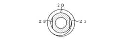
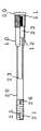
本発明を図に基づいて説明する。図1は、一実施例を示す一部破断側面図である。図2は、図1に示した実施例の組立図である。図3は、図2の縦断面図である。図4は、図2のIV−IV断面図である。図5は、図2のV−V断面図である。図6は、図2のVI−VI断面図である。
【0025】
本発明のインプラントスクリューは、一端の外周にネジ山21を備え、他端に基部22を備え、該基部22にレンチ用の角穴27またはドライバー用の溝(図示せず)を備える内スクリュー20、および、該基部22の周囲に同軸状に配置される円管状の外スクリュー10からなる。内スクリュー20のネジ山21と外スクリュー10のネジ山11は同一回転方向であり、内スクリュー20と外スクリュー10の相対的回転を抑止する噛合構造23、13を、内スクリュー20の外周面と外スクリュー10の内周面にそれぞれ備える。従って、外スクリュー10と内スクリュー20は一体になって回転し、軸方向にのみスライド可能である。図示した実施例では、噛合部23は、円柱側面に設ける平坦部とし(図4参照)、噛合部13は、該噛合部23に対向する平坦な凸部とする(図5参照)。
【0026】
材質は、強度が高く、生体親和性と耐腐食性を有するチタン合金がよい。
【0027】
内スクリュー20は、例えば、外径6mm×内径3.4mm×90mmの円管状で、最大外径8mm、1.75mmピッチのネジ山21を備え、間隔が5mmの平行な面の噛合部23を備え(図1、2の向こう側に相対する噛合部を備える。)、基部22は、φ7.2mm×11mmで、一端にM5の六角穴27を備える。内スクリューの軸中心に貫通する孔は、φ3mmのガイドピンを通過させる目的で使用され、小径で短く、骨への挿入にガイドピンを必要としないインプラントスクリューでは、中実にして、該孔を設けなくてもよい。
【0028】
外スクリュー10は、例えば、外径9mm×内径7.25mm×30mmの円管状で、最大外径11mm、前記内スクリュー20のネジ山21のピッチよりも小さい1.5mmピッチのネジ山11を備え、係合部12は内スクリュー20が挿通可能なφ6.05mmで、間隔が5.05mmの平行で平坦な噛合部13を備える。該噛合部13は、内スクリュー20の噛合部23を挟んで位置し、内スクリュー20と外スクリュー10とが相対的に回転するのを抑止する。組み立てられたインプラントスクリューは、最大長さが約95mmとなる。
【0029】
前述した寸法から分かるように、前記内スクリュー20の基部22の外周に対し、前記外スクリュー10の内周面の係合部12の内周は小さい。従って、外スクリュー10の係合部12が、前記基部22に当接することにより、内スクリュー20が図1の左方向に抜けることがない。また、外スクリュー10の噛合部13が、内スクリュー20の噛合部23の端部に当接することにより、内スクリュー20が図1の右方向に抜けることもない。外スクリュー10は内スクリュー20に対して、軸方向の一定範囲でスライド可能である。
【0030】
あるいは、内スクリュー20の噛合部23をネジ山21にまで達するようにして、外スクリュー10の噛合部13が該ネジ山21の端部に当接することにより、外スクリュー10のスライドの制限、および離脱の防止とする構造でもよい。
【0031】
あるいは、内スクリュー20のネジ山21を、外スクリュー10(係合部12を含めて、)の内周より小さくしてもよく、この場合は、内スクリュー20が図1の右方向に抜け、分離される。このように分離可能とすることにより、後述する組立て作業が必要なくなり、安価に製造可能で、取扱い性がよくなる。
【0032】
内スクリュー20のネジ山21は、セルフタップ機構25および逆セルフタップ機構26を備えるとよい。図示しないが、外スクリュー10のネジ山11に、同様のセルフタップ機構および逆セルフタップ機構を備えてもよい。
【0033】
本発明のインプラントスクリューの組立て方法は、内スクリュー20の噛合部23に、外スクリュー10の噛合部13を向かい合わせた状態で、内スクリュー20に外スクリュー10を挿入し、内スクリュー20のかしめ部24aに、基部22のかしめ部24bをはめてかしめるか、接着などの周知技術により基部22を固着する。
【0034】
本発明のインプラントスクリューを大腿骨頸部に挿入する方法について、以下に説明する。図7は、大腿骨頸部に本発明のインプラントスクリューを2本挿入した断面図を示す。
【0035】
骨折部40を向かい合わせて整復し、大腿骨頸部30の外側皮質32から、外スクリュー10に合わせた穴30aを2カ所設け、海綿骨33に、内スクリュー20に合わせた穴を設ける。あるいは、先にガイドピン(図示せず)を刺し込み、該ガイドピンに合わせて、穴を設けるようにするとよい。該ガイドピンは、本発明のインプラントスクリューを挿入後、抜き取る。
【0036】
次に、外スクリュー10のネジ山に合わせたタッピングを穴30aの縁に施し、内スクリュー20に合わせたタッピングを穴30aの先端側に施す。そして、前記角穴27(図3)にレンチ(図示せず)を差し込み、内スクリュー20を穴30aにねじ込む。外スクリュー10は内スクリュー20に対して回転しない構造なので、内スクリュー20をねじ込む回転により、外スクリュー10がねじ込まれる。内スクリュー20の基部22が、外スクリュー10の係合部12に当接する位置から(図1参照)、骨折部40に圧迫力を与えることができるようになり、レンチを回転させる力により該圧迫力を加減して挿入を終了する。外スクリュー10は、皮質32から突出させた状態でも、皮質に留めた状態でも、海綿骨まで埋入させた状態でもよい。
【0037】
骨折部40の圧迫力は持続して与え続けられるが、内スクリュー20と外スクリュー10とは、係合部12と基部22が当接しているのみであり、外部から力が加わった際には、係合部12と基部22が離れ、外部からの力がインプラントスクリューと骨の組織との間に作用することがないという効果を有する。
【0038】
図1、2に示したように、セルフタッピング25を施したインプラントスクリューを使用すれば、必ずしも前述のタッピング作業を必要とせず、容易に穴開け作業をすることが可能である。
【0039】
また、経過観察の後、骨折部40の骨癒合を確認してから、本発明のインプラントスクリューを抜き取ることが可能である。この際、逆セルフタッピング26を備えていれば、容易に抜き取ることができる。
【0040】
また、本発明の他の実施の形態として、前記外スクリュー10のネジ山11のピッチと、前記内スクリュー20のネジ山21のピッチとを同じとする(図示せず)。2つのネジ山11、21のピッチが同じインプラントスクリューを、前述のように挿入しても、骨折部に押圧力を与えない。従って、該インプラントスクリューを、前述のネジ山11のピッチがネジ山21のピッチより小さいインプラントスクリューと同時に使用することにより、骨折部にかける圧迫力を一本のインプラントスクリューで加減できるという効果を得られる。
【0041】
また、骨折部のずれが小さい場合には、骨折部に圧迫力をほとんどかけない方がよい場合もある。この場合にも、本実施例の2つのネジ山11、21のピッチが同じインプラントスクリューを使用する。内スクリュー20と外スクリュー10とが、係合部12と基部22を当接させるだけの関係にあるので、骨折部に圧迫力を与えないでおいて、経過観察の途中で、他の方法により骨折部に大きな圧迫力をかける治療を行うことも可能である。
【0042】
骨折部にかける圧迫力は、2つのネジ山のピッチにより、任意に設計が可能である。また、患部の形状や状態に合わせて、インプラントスクリューの長さや本数、太さを適宜選択すればよい。
【0043】
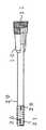
異なる実施例のインプラントスクリューの一部破断側面図を図8に示し、組立縦断面図を図9に示した。
【0044】
本実施例のインプラントスクリューには、前述の実施例に圧迫力調整用ネジ50を、さらに有する。また、内スクリュー20の内周に、ネジ山28を設ける。圧迫力調整用ネジ50には、該ネジ山28に合うネジ部51と、鍔部52とを備える。鍔部52をボックスレンチ用に六角形状としてもよいし、あるいは鍔部52に、レンチ用の角穴やドライバー用の溝を備えてもよい。ネジ部51を前記ネジ山28に締めてゆくことにより、鍔部52が、外スクリュー10に当接し、内スクリュー20の基部22が外スクリュー10の係合部12から離れ、骨折部に与える圧迫力を増大させることができる。前述のような外部からの力が加わった際には、鍔部52と外スクリュー10とが離れ、外部からの外がインプラントスクリューと骨の組織との間に作用することはない。
【0045】
該圧迫力調整用ネジ50は、インプラントスクリューを患部に設置する時に備えておくと効果的であるが、経過観察途中で設置してもよい。
【0046】
本発明のインプラントスクリューの抜取り時に、回転中心に貫通する孔を備えるレンチを使用し、前記ネジ山28に補助具を締着させると、インプラントスクリューを回転させることが容易となる効果も有する。
【0047】
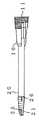
図10に本発明の異なる実施例の一部破断側面図を示し、図11に組立断面図を示した。また、図12は図10のXII-XII断面図である。図示したように、内スクリュー20は単純円筒形とし、内スクリュー20の基部22の外周面の断面を、例えば六角形とし、同様に、外スクリュー10の内周面の断面を六角形とする。前述の噛合部13(図3)および噛合部23(図2)の代わりに、基部22の外周面および外スクリュー10の内周面が、内スクリュー20と外スクリュー10の相対的回旋を抑止する。また、外スクリュー10の内周面が、レンチ用の角穴を兼用するので、内スクリュー20の基部22に設けていた六角穴27(図3)は必要ではなくなる。その他の形状は前実施例と同様とする。
【0048】
本実施例のように、噛合構造を内スクリューの基部に設け、回旋用の六角穴を兼用させると、加工しやすい。また、外スクリューの端部に、ドライバー用の溝を設けてもよい。
【0049】
実際の埋込み時には、このように、外スクリューに力を加えて回転させることにより、骨に容易に挿入することができた。
【0050】
また、外スクリューをテーパー(先細り)にし、骨への固定力を高めてもよい。または、外スクリューのネジ山だけをテーパー(先細り)にしてもよい。
【0051】
図13に本発明の異なる実施例の一部破断側面図を示した。本実施例では、外スクリューをテーパー状にした。従って、外スクリューのネジ山もテーパー状である。
【0052】
また、図14にさらに異なる実施例の一部破断側面図を示した。本実施例では、外スクリューおよび内スクリューのネジ山部分をテーパー状にした。
【0053】
これらのように、ネジ山をテーパー状としたので、ネジ山が骨に食い込み、骨への固定力を増大させることができる。
【0054】
本発明の説明のために使用し、図示した実施例の部品の材質や形状により本発明は制限されない。
【0055】
【発明の効果】
以上、詳細に説明したように、本発明のインプラントスクリューは、一度の作業により挿入することができる。また、スクリュー挿入時および挿入後、骨折部に任意の圧迫力を与えることができる。さらに、外部からの力がインプラントスクリューと骨の組織との間に悪影響を及ぼすことを避けることができる。
【0056】
外スクリューと内スクリューとを分離可能とすると、製造コストが安くすみ、あるいは、外スクリューが内スクリューと一体に組立てられていると、患部への挿入作業が容易となる。
【0057】
また、セルフタッピングを設けることにより、挿入前のタッピング作業が省略可能で、逆セルフタッピングを設けることにより、抜取りが容易になる。
【0058】
2つのネジ山のピッチが同じインプラントスクリューを、外スクリューのネジ山のピッチが内スクリューのネジ山のピッチより小さいインプラントスクリューと同時に使用することにより、骨折部にかける圧迫力を一本のインプラントスクリューで加減でき、過度の圧迫力としないという効果を得られる。
【0059】
また、内スクリューと外スクリューとの噛合構造を、外スクリュー内周面と内スクリューの基部とに備えてもよい。その場合、断面形状を六角形とすると、六角レンチ挿入用穴を兼用できる。また、骨への挿入が容易となる。
【0060】
さらに、ネジ山をテーパー状に形成すると、骨への固定力が増大するという効果も有する。
【図面の簡単な説明】
【図1】 本発明のインプラントスクリューの一実施例を示す一部破断側面図である。
【図2】 図1に示した実施例の組立図である。
【図3】 図2の縦断面図である。
【図4】 図2のIV−IV断面図である。
【図5】 図2のV−V断面図である。
【図6】 図2のVI−VI断面図である。
【図7】 大腿骨頸部に本発明のインプラントスクリューを2本挿入した断面図を示す。
【図8】 本発明のインプラントスクリューの異なる実施例を示す一部破断側面図である。
【図9】 図8に示した実施例の組立縦断面図である。
【図10】 本発明の異なる実施例を示す一部破断側面図である。
【図11】 図10に示した実施例の組立断面図である。
【図12】 図10のXII-XII断面図である。
【図13】 本発明の異なる実施例を示す一部破断側面図である。
【図14】 本発明の異なる実施例を示す一部破断側面図である。
【符号の説明】
10 外スクリュー
11、21 ネジ山
11a、11b、21a、21b セルフタップ
12 係合部
13、23 噛合部
20 内スクリュー
22 基部
24a、24b かしめ部
25、26 セルフタップ
27 六角穴
28 ネジ山
30 大腿骨頸部
30a 穴
31 骨頭
32 皮質
33 海綿骨
40 骨折部
50 圧迫力調整用ネジ
51 ネジ部
52 鍔部[0001]
BACKGROUND OF THE INVENTION
The present invention relates to an osteosynthesis material used for osteosynthesis, and more particularly to an implant screw that is inserted into the cancellous bone of the bone and applies a compression force to the fractured portion.
[0002]
[Prior art]
In osteosynthesis in the affected area, for example, one bone (large distal bone fragment) such as the femoral neck and trochanter, and the other bone (proximal trochanter, including the head) The implant screw is inserted over the distal bone fragment and fixed in an appropriate reduced position to promote bone healing at the fracture.
[0003]
Conventionally, there has been proposed an implant screw comprising an inner screw having a screw thread at the tip, and an outer screw having a through-hole through which the inner screw can be inserted, a screw thread on the outer periphery, and being arranged coaxially. The inner screw is provided with a driver groove or a square hole for a wrench, and the outer screw is provided with a head for a box wrench so that the respective rotation operations can be performed.
[0004]
The method for installing the implant screw is as follows.
[0005]
A hole for inserting an external screw is provided from the cortex of one bone to the middle of the cancellous bone of the bone. A hole for inserting the inner screw is further provided on the bottom surface of the hole so as to penetrate the fracture. The hole edge is tapped according to the thread of the outer screw, and the hole tip is tapped according to the thread of the inner screw.
[0006]
Next, insert the inner screw into the hole, rotate it with a screwdriver, etc., and insert it close to the cortex of the bone on the tip side. Then, the outer screw is coaxially inserted with the inner screw and inserted into the hole, and is rotated with a box wrench or the like, and is fastened with the head protruding from the hole. That is, the inner screw and the outer screw are arranged coaxially, but are not fixed to each other so that the fracture portion is not displaced.
[0007]
About 1 to 3 of such implant screws are inserted and fixed so that the fractured portion is not displaced. Then, after observing for several months to several years, after confirming bone fusion, the state is judged and if necessary, all implant screws are removed.
[0008]
When the implant screw is used, a load is applied so as to compress the fractured portion by the load, behavior, and movement, and bone fusion of the fractured portion is promoted. Since it is known that the formation of bone is promoted by applying a compression stimulus to the fractured part, the load is used as a compression stimulus. However, it takes a lot of time to insert the inner screw and the outer screw one after another, the rotation force can be generated between the inner and outer screws, so the fixing force is weak, and the compression force is not applied to the fracture when inserting the screw. There was a problem.
[0009]
In order to compress the fracture more strongly, a Herbert screw having two threads with different pitches at both ends has been proposed.
[0010]
The Herbert screw has a speed at which the screw thread on the rear end side is inserted into the cancellous bone on the rear end side, compared to the speed at which the screw thread on the front end side is inserted into the cancellous bone of the bone on the front end side. Therefore, the operator can apply the compression force applied to the fractured part while adjusting the pressure. Moreover, the trouble of inserting two screws can be saved, and the extraction work can be easily performed.
[0011]
Use of the Herbert screw has an effect that the compression force applied to the fractured portion can be made constant by one insertion. However, an external force is applied between the Herbert screw and the bone tissue, and the screw deviation, cancellous bone destruction, and the compression force applied to the fractured part are only immediately after the screw insertion. There is a problem that the pressure stimulus is not applied.
[0012]
[Problems to be solved by the invention]
In order to solve the above problems, the present invention can be inserted without trouble, has excellent fixing force, can apply a compression force to the fractured part at the time of screw insertion and after screw insertion, and can apply external force. It is an object of the present invention to provide an implant screw that can be released and easily extracted.
[0013]
[Means for Solving the Problems]
The implant screw of the present invention has a thread on the outer periphery of one end, a base on the other end, an inner screw having a wrench square hole or a driver groove on the base, and a screw on at least a part of the outer periphery. An implant screw comprising an outer screw coaxially disposed around the base of the inner screw, wherein the inner screw thread and the outer screw thread have the same rotational direction, and the inner screw and the outer screw By providing a meshing structure that suppresses relative rotation on the outer peripheral surface of the inner screw and the inner peripheral surface of the outer screw, the outer screw and the inner screw can slide only in the axial direction.
[0014]
Alternatively, an inner screw having a thread on the outer periphery of one end and a base on the other end, and a screw thread on at least a part of the outer periphery, a square hole for a wrench or a groove for a driver, and a base of the inner screw You may make it consist of the outer screw arrange | positioned coaxially around.
[0015]
Further, the meshing structure may be an intermediate portion or a base portion of a non-circular cross section for the inner screw, and a cross section corresponding to the intermediate portion or the base portion for the outer screw.
[0016]
An implant screw in which the pitch of the thread of the outer screw is smaller than the pitch of the thread of the inner screw, the pitch of the thread of the outer screw, and the pitch of the thread of the inner screw are the same Use properly.
[0017]
A first engagement structure that contacts the base of the inner screw is provided on the inner peripheral portion of the outer screw so that a force can be applied between the inner screw and the outer screw.
[0018]
In addition, a second engagement structure that abuts on the base side of the thread of the inner screw or a protrusion provided on the base side to prevent the outer screw from being detached from the periphery of the inner screw is provided with an inner side of the outer screw. It may be provided on the periphery. Alternatively, both the state where the inner periphery of the outer screw is larger than the thread of the inner screw and the outer screw stays around the inner screw and the state where the outer screw is separated from the inner screw are possible. It is good.
[0019]
It is preferable to provide a hole penetrating the shaft center of the inner screw at least on the base side.
[0020]
It is preferable to provide a screw thread on the base side of the inner periphery of the hole that penetrates the shaft center of the inner screw.
[0021]
Compression force adjustment comprising: a threaded portion that matches the thread provided in a hole that penetrates the shaft center of the inner screw; and a flange that contacts the outer screw when the threaded portion enters the thread It is preferable that a relative position of the inner screw with respect to the outer screw can be slid by having a working screw and the screw portion entering the screw thread.
[0022]
The thread of the inner screw and the thread of the outer screw may include a self-tapping mechanism and a reverse self-tapping mechanism.
[0023]
The thread of the inner screw or the thread of the outer screw may be tapered.
[0024]
DETAILED DESCRIPTION OF THE INVENTION
The present invention will be described with reference to the drawings. FIG. 1 is a partially broken side view showing an embodiment. FIG. 2 is an assembly view of the embodiment shown in FIG. FIG. 3 is a longitudinal sectional view of FIG. 4 is a cross-sectional view taken along the line IV-IV in FIG. 5 is a cross-sectional view taken along the line VV in FIG. 6 is a cross-sectional view taken along the line VI-VI in FIG.
[0025]
The implant screw of the present invention is provided with a
[0026]
The material is preferably a titanium alloy having high strength, biocompatibility and corrosion resistance.
[0027]
The
[0028]
The
[0029]
As can be seen from the above-described dimensions, the inner periphery of the engaging
[0030]
Alternatively, when the meshing
[0031]
Alternatively, the
[0032]
The
[0033]
The assembly method of the implant screw of the present invention is such that the
[0034]
A method for inserting the implant screw of the present invention into the femoral neck will be described below. FIG. 7 shows a sectional view in which two implant screws of the present invention are inserted into the femoral neck.
[0035]
The fractured
[0036]
Next, tapping according to the thread of the
[0037]
Although the compression force of the fractured
[0038]
As shown in FIGS. 1 and 2, if an implant screw subjected to self-tapping 25 is used, the above-described tapping operation is not necessarily required, and the hole can be easily drilled.
[0039]
In addition, after the follow-up observation, it is possible to extract the implant screw of the present invention after confirming the bone fusion of the fractured
[0040]
As another embodiment of the present invention, the pitch of the
[0041]
In addition, when the displacement of the fracture portion is small, it may be better to apply almost no compression force to the fracture portion. Also in this case, an implant screw having the same pitch of the two
[0042]
The compression force applied to the fracture can be arbitrarily designed by the pitch of the two threads. Moreover, what is necessary is just to select the length, number, and thickness of an implant screw suitably according to the shape and state of an affected part.
[0043]
FIG. 8 shows a partially cutaway side view of an implant screw of a different embodiment, and FIG. 9 shows an assembled longitudinal sectional view.
[0044]
The implant screw of the present embodiment further includes a compression
[0045]
The compression
[0046]
When the wrench having a hole penetrating the rotation center is used and the auxiliary tool is fastened to the
[0047]
FIG. 10 shows a partially broken side view of a different embodiment of the present invention, and FIG. 11 shows an assembled cross-sectional view. 12 is a cross-sectional view taken along the line XII-XII in FIG. As shown in the figure, the
[0048]
As in this embodiment, when the meshing structure is provided at the base of the inner screw and the hexagonal hole for rotation is also used, it is easy to process. Moreover, you may provide the groove | channel for drivers in the edge part of an outer screw.
[0049]
At the time of actual implantation, it was possible to easily insert the bone into the bone by rotating the external screw by applying a force.
[0050]
Further, the external screw may be tapered (tapered) to increase the fixing force to the bone. Alternatively, only the thread of the outer screw may be tapered (tapered).
[0051]
FIG. 13 shows a partially broken side view of a different embodiment of the present invention. In this embodiment, the outer screw is tapered. Therefore, the thread of the outer screw is also tapered.
[0052]
FIG. 14 shows a partially broken side view of another embodiment. In this example, the threaded portions of the outer screw and the inner screw were tapered.
[0053]
As described above, since the thread is tapered, the thread can bite into the bone, and the fixing force to the bone can be increased.
[0054]
The present invention is not limited by the material and shape of the components used in the illustrated embodiment, which are used for explaining the present invention.
[0055]
【The invention's effect】
As described above in detail, the implant screw of the present invention can be inserted by a single operation. Moreover, arbitrary compression force can be given to a fractured part at the time of screw insertion and after insertion. Furthermore, external forces can be avoided from adversely affecting the implant screw and the bone tissue.
[0056]
If the outer screw and the inner screw can be separated, the manufacturing cost can be reduced, or if the outer screw is assembled integrally with the inner screw, the insertion operation into the affected area becomes easy.
[0057]
In addition, by providing self-tapping, tapping work before insertion can be omitted, and by providing reverse self-tapping, extraction is facilitated.
[0058]
By using an implant screw with the same pitch of two threads at the same time as an implant screw whose outer screw thread pitch is smaller than that of the inner screw thread, the compression force applied to the fracture part is one implant screw. The effect of not being excessive pressure can be obtained.
[0059]
Moreover, you may provide the meshing structure of an inner screw and an outer screw in the outer peripheral surface of an outer screw, and the base part of an inner screw. In that case, if the cross-sectional shape is a hexagon, a hexagon wrench insertion hole can also be used. Moreover, the insertion into the bone becomes easy.
[0060]
Furthermore, when the thread is formed in a tapered shape, there is an effect that the fixing force to the bone is increased.
[Brief description of the drawings]
FIG. 1 is a partially broken side view showing an embodiment of an implant screw of the present invention.
FIG. 2 is an assembly view of the embodiment shown in FIG. 1;
3 is a longitudinal sectional view of FIG.
4 is a cross-sectional view taken along the line IV-IV in FIG.
5 is a VV cross-sectional view of FIG.
6 is a cross-sectional view taken along the line VI-VI in FIG.
FIG. 7 shows a sectional view in which two implant screws of the present invention are inserted into a femoral neck.
FIG. 8 is a partially cutaway side view showing a different embodiment of the implant screw of the present invention.
9 is an assembly longitudinal sectional view of the embodiment shown in FIG. 8. FIG.
FIG. 10 is a partially broken side view showing a different embodiment of the present invention.
11 is an assembled cross-sectional view of the embodiment shown in FIG.
12 is a cross-sectional view taken along the line XII-XII in FIG.
FIG. 13 is a partially broken side view showing a different embodiment of the present invention.
FIG. 14 is a partially broken side view showing a different embodiment of the present invention.
[Explanation of symbols]
10
Claims (9)
Translated fromJapanesePriority Applications (2)
| Application Number | Priority Date | Filing Date | Title |
|---|---|---|---|
| JP2000136109AJP4336023B2 (en) | 1999-05-12 | 2000-05-09 | Implant screw |
| US09/852,133US20010049528A1 (en) | 1999-05-12 | 2001-05-09 | Implant screw |
Applications Claiming Priority (3)
| Application Number | Priority Date | Filing Date | Title |
|---|---|---|---|
| JP11-131954 | 1999-05-12 | ||
| JP13195499 | 1999-05-12 | ||
| JP2000136109AJP4336023B2 (en) | 1999-05-12 | 2000-05-09 | Implant screw |
Publications (2)
| Publication Number | Publication Date |
|---|---|
| JP2001025471A JP2001025471A (en) | 2001-01-30 |
| JP4336023B2true JP4336023B2 (en) | 2009-09-30 |
Family
ID=26466644
Family Applications (1)
| Application Number | Title | Priority Date | Filing Date |
|---|---|---|---|
| JP2000136109AExpired - LifetimeJP4336023B2 (en) | 1999-05-12 | 2000-05-09 | Implant screw |
Country Status (2)
| Country | Link |
|---|---|
| US (1) | US20010049528A1 (en) |
| JP (1) | JP4336023B2 (en) |
Families Citing this family (34)
| Publication number | Priority date | Publication date | Assignee | Title |
|---|---|---|---|---|
| FR2841459B1 (en)* | 2002-06-28 | 2004-08-27 | Sanortho | MINIMALLY INVASIVE OSTEOSYNTHESIS DEVICE, PARTICULARLY HIP SCREWS |
| DE10246386B4 (en)* | 2002-10-04 | 2008-08-07 | Biedermann Motech Gmbh | Bone screw, bone fixation device and retaining element |
| DE10260222B4 (en)* | 2002-12-20 | 2008-01-03 | Biedermann Motech Gmbh | Tubular element for an implant and implant to be used in spine or bone surgery with such an element |
| US7582107B2 (en)* | 2003-02-03 | 2009-09-01 | Integra Lifesciences Corporation | Compression screw apparatuses, systems and methods |
| DE10305348A1 (en)* | 2003-02-10 | 2004-08-26 | Cell Center Cologne Gmbh | Dynamic epiphyseal telescopic screw |
| US7044953B2 (en)* | 2003-02-27 | 2006-05-16 | Stryker Leibinger Gmbh & Co. Kg | Compression bone screw |
| AU2003901971A0 (en)* | 2003-04-23 | 2003-05-15 | Dugal Simon Stewart James | A fixation device and method of fixation |
| CN100393287C (en)* | 2003-09-18 | 2008-06-11 | 斯恩蒂斯有限公司 | Device for treating femoral fractures |
| DE102005007674B4 (en)* | 2005-02-19 | 2007-02-01 | Aesculap Ag & Co. Kg | Orthopedic fixation system |
| US20070173838A1 (en)* | 2006-01-12 | 2007-07-26 | Kung-Chia Li | Femoral head and neck strengthening device |
| WO2007106774A2 (en)* | 2006-03-13 | 2007-09-20 | The Johns Hopkins University | Orthopedic screw system |
| EP1905367A1 (en)* | 2006-09-28 | 2008-04-02 | Orthofix S.r.l. | Intramedullary osteosynthesis device |
| JP4978906B2 (en)* | 2006-10-17 | 2012-07-18 | 周 中村 | Fracture fixation device for femoral trochanteric fracture |
| US8398636B2 (en)* | 2007-04-19 | 2013-03-19 | Stryker Trauma Gmbh | Hip fracture device with barrel and end cap for load control |
| EP2134279B1 (en) | 2007-04-19 | 2017-01-04 | Stryker European Holdings I, LLC | Hip fracture device with static locking mechanism allowing compression |
| CN100500110C (en)* | 2007-09-18 | 2009-06-17 | 北京大学人民医院 | Anti-rotation self-locking fracture internal fixator |
| US8771315B2 (en) | 2008-12-15 | 2014-07-08 | Smith & Nephew, Inc. | Composite anchor |
| US9592084B2 (en)* | 2010-08-27 | 2017-03-14 | William P. Grant | Foot beam insert |
| JP5989759B2 (en)* | 2011-03-22 | 2016-09-07 | スミス アンド ネフュー インコーポレーテッド | Mooring system and feeding device for use with the mooring system |
| US9161794B2 (en) | 2011-04-14 | 2015-10-20 | Globus Medical, Inc. | Expanding spinal anchor |
| US9480436B1 (en)* | 2011-07-01 | 2016-11-01 | Atg R&D Limited | Probe housing assembly |
| US9782209B2 (en)* | 2012-10-03 | 2017-10-10 | Rtg Scientific | Medical fastener |
| US20140214034A1 (en)* | 2013-01-25 | 2014-07-31 | Fady Rayes | Cannulated telescopic femoral neck screw device and related fixation method |
| US20140243826A1 (en)* | 2013-02-28 | 2014-08-28 | Yechiel Gotfried | Method for connecting fractured bone |
| US9526547B2 (en) | 2013-03-06 | 2016-12-27 | Rgt Scientific Inc. | Bone screw |
| CN105188562B (en) | 2013-03-06 | 2019-02-26 | 史密夫和内修有限公司 | Micro Anchor |
| FR3013581B1 (en)* | 2013-11-25 | 2016-10-21 | Iceram | COMPRESSIVE CEPHALIC SCREW FOR ORTHOPEDIC SURGERY |
| US10166055B2 (en)* | 2014-05-16 | 2019-01-01 | Biomet C.V. | Method and apparatus for bone fixation |
| US10390865B2 (en)* | 2014-05-16 | 2019-08-27 | Stryker European Holdings I, Llc | Orthopedic locking screw for an orthopedic fastening system and method of securing an orthopedic locking screw |
| WO2017086953A1 (en) | 2015-11-18 | 2017-05-26 | Stryker European Holdings I, Llc | Orthopedic locking screw for an orthopedic fastening system |
| KR101767210B1 (en)* | 2015-12-11 | 2017-08-10 | (주)티디엠 | Fixing device for treating femur fracture |
| US20180071000A1 (en)* | 2016-09-13 | 2018-03-15 | Arthrex, Inc. | Telescoping fixation devices and methods of use |
| US11253304B2 (en)* | 2018-01-03 | 2022-02-22 | Glw, Inc. | Hybrid cannulated orthopedic screws |
| WO2021151151A1 (en)* | 2020-01-31 | 2021-08-05 | The Sydney Children's Hospitals Network (Randwick And Westmead) | Variable length bone screw |
- 2000
- 2000-05-09JPJP2000136109Apatent/JP4336023B2/ennot_activeExpired - Lifetime
- 2001
- 2001-05-09USUS09/852,133patent/US20010049528A1/ennot_activeAbandoned
Also Published As
| Publication number | Publication date |
|---|---|
| US20010049528A1 (en) | 2001-12-06 |
| JP2001025471A (en) | 2001-01-30 |
Similar Documents
| Publication | Publication Date | Title |
|---|---|---|
| JP4336023B2 (en) | Implant screw | |
| EP1916955B1 (en) | Headless compression screw with integrated reduction-compression instrument | |
| EP3177223B1 (en) | Screw with insertion post | |
| CA2444698C (en) | Apparatus for attaching fractured sections of bone | |
| US4175555A (en) | Bone screw | |
| DE102005007674B4 (en) | Orthopedic fixation system | |
| EP1016382B1 (en) | Femoral neck screw | |
| US4657001A (en) | Antirotational hip screw | |
| EP1940306B1 (en) | Thread-forming screw | |
| AU765847B2 (en) | Allograft bone fixation screw method and apparatus | |
| DE60226248T3 (en) | BONE IMPLANT | |
| US9247975B2 (en) | Bone screw set | |
| US20070233125A1 (en) | Bone screw with selectively securable washer | |
| EP1287787A1 (en) | Implant for the fixation of bone fractures | |
| CA2336930C (en) | Osteosynthesis screw | |
| EP1982665B1 (en) | Compression screw with wire element | |
| DE102006007541A1 (en) | Implant for placing in toothless lower or upper jaws for dental prosthesis attachment, has micro thread extending directly to upper end of outer circumference of implant body, which returns inwards at upper end of micro thread | |
| DE102004014036B4 (en) | Device for intraoperable fixation of bone fragments | |
| WO1997010767A1 (en) | Securing pin | |
| JPH07184921A (en) | Screw for fixing bone | |
| DE202005002678U1 (en) | Orthopaedic fixing system for bone fragments, comprises support screw, bone plate and support sleeve with identical pitch and reduced width thread turns |
Legal Events
| Date | Code | Title | Description |
|---|---|---|---|
| AA64 | Notification of invalidation of claim of internal priority (with term) | Free format text:JAPANESE INTERMEDIATE CODE: A241764 Effective date:20000614 | |
| A521 | Written amendment | Free format text:JAPANESE INTERMEDIATE CODE: A523 Effective date:20000630 | |
| A521 | Written amendment | Free format text:JAPANESE INTERMEDIATE CODE: A821 Effective date:20000630 | |
| A621 | Written request for application examination | Free format text:JAPANESE INTERMEDIATE CODE: A621 Effective date:20070508 | |
| A977 | Report on retrieval | Free format text:JAPANESE INTERMEDIATE CODE: A971007 Effective date:20080912 | |
| A131 | Notification of reasons for refusal | Free format text:JAPANESE INTERMEDIATE CODE: A131 Effective date:20080924 | |
| A521 | Written amendment | Free format text:JAPANESE INTERMEDIATE CODE: A523 Effective date:20081125 | |
| A131 | Notification of reasons for refusal | Free format text:JAPANESE INTERMEDIATE CODE: A131 Effective date:20090120 | |
| A521 | Written amendment | Free format text:JAPANESE INTERMEDIATE CODE: A523 Effective date:20090323 | |
| A521 | Written amendment | Free format text:JAPANESE INTERMEDIATE CODE: A523 Effective date:20090428 | |
| A131 | Notification of reasons for refusal | Free format text:JAPANESE INTERMEDIATE CODE: A131 Effective date:20090428 | |
| A521 | Written amendment | Free format text:JAPANESE INTERMEDIATE CODE: A523 Effective date:20090428 | |
| TRDD | Decision of grant or rejection written | ||
| A01 | Written decision to grant a patent or to grant a registration (utility model) | Free format text:JAPANESE INTERMEDIATE CODE: A01 Effective date:20090609 | |
| A01 | Written decision to grant a patent or to grant a registration (utility model) | Free format text:JAPANESE INTERMEDIATE CODE: A01 | |
| A61 | First payment of annual fees (during grant procedure) | Free format text:JAPANESE INTERMEDIATE CODE: A61 Effective date:20090626 | |
| FPAY | Renewal fee payment (event date is renewal date of database) | Free format text:PAYMENT UNTIL: 20120703 Year of fee payment:3 | |
| R150 | Certificate of patent or registration of utility model | Ref document number:4336023 Country of ref document:JP Free format text:JAPANESE INTERMEDIATE CODE: R150 Free format text:JAPANESE INTERMEDIATE CODE: R150 | |
| FPAY | Renewal fee payment (event date is renewal date of database) | Free format text:PAYMENT UNTIL: 20150703 Year of fee payment:6 | |
| R250 | Receipt of annual fees | Free format text:JAPANESE INTERMEDIATE CODE: R250 | |
| R250 | Receipt of annual fees | Free format text:JAPANESE INTERMEDIATE CODE: R250 | |
| R250 | Receipt of annual fees | Free format text:JAPANESE INTERMEDIATE CODE: R250 | |
| EXPY | Cancellation because of completion of term |