JP4335701B2 - Cartridge type liquid feeding container - Google Patents
Cartridge type liquid feeding containerDownload PDFInfo
- Publication number
- JP4335701B2 JP4335701B2JP2004012326AJP2004012326AJP4335701B2JP 4335701 B2JP4335701 B2JP 4335701B2JP 2004012326 AJP2004012326 AJP 2004012326AJP 2004012326 AJP2004012326 AJP 2004012326AJP 4335701 B2JP4335701 B2JP 4335701B2
- Authority
- JP
- Japan
- Prior art keywords
- cartridge
- piston rod
- main body
- tip
- liquid
- Prior art date
- Legal status (The legal status is an assumption and is not a legal conclusion. Google has not performed a legal analysis and makes no representation as to the accuracy of the status listed.)
- Expired - Lifetime
Links
- 239000007788liquidSubstances0.000titleclaimsdescription91
- 230000002093peripheral effectEffects0.000claimsdescription25
- 238000006243chemical reactionMethods0.000claimsdescription5
- 239000011248coating agentSubstances0.000description4
- 238000000576coating methodMethods0.000description4
- 210000000078clawAnatomy0.000description2
- 239000002537cosmeticSubstances0.000description2
- 230000008878couplingEffects0.000description2
- 238000010168coupling processMethods0.000description2
- 238000005859coupling reactionMethods0.000description2
- 238000010586diagramMethods0.000description2
- 238000005192partitionMethods0.000description2
- 241000255925DipteraSpecies0.000description1
- 239000000428dustSubstances0.000description1
- 239000000463materialSubstances0.000description1
- 239000002699waste materialSubstances0.000description1
Images


Classifications
- B—PERFORMING OPERATIONS; TRANSPORTING
- B05—SPRAYING OR ATOMISING IN GENERAL; APPLYING FLUENT MATERIALS TO SURFACES, IN GENERAL
- B05C—APPARATUS FOR APPLYING FLUENT MATERIALS TO SURFACES, IN GENERAL
- B05C17/00—Hand tools or apparatus using hand held tools, for applying liquids or other fluent materials to, for spreading applied liquids or other fluent materials on, or for partially removing applied liquids or other fluent materials from, surfaces
- B05C17/005—Hand tools or apparatus using hand held tools, for applying liquids or other fluent materials to, for spreading applied liquids or other fluent materials on, or for partially removing applied liquids or other fluent materials from, surfaces for discharging material from a reservoir or container located in or on the hand tool through an outlet orifice by pressure without using surface contacting members like pads or brushes
- B—PERFORMING OPERATIONS; TRANSPORTING
- B43—WRITING OR DRAWING IMPLEMENTS; BUREAU ACCESSORIES
- B43L—ARTICLES FOR WRITING OR DRAWING UPON; WRITING OR DRAWING AIDS; ACCESSORIES FOR WRITING OR DRAWING
- B43L19/00—Erasers, rubbers, or erasing devices; Holders therefor
- B43L19/0018—Erasers, rubbers, or erasing devices; Holders therefor with fluids
- A—HUMAN NECESSITIES
- A45—HAND OR TRAVELLING ARTICLES
- A45D—HAIRDRESSING OR SHAVING EQUIPMENT; EQUIPMENT FOR COSMETICS OR COSMETIC TREATMENTS, e.g. FOR MANICURING OR PEDICURING
- A45D34/00—Containers or accessories specially adapted for handling liquid toiletry or cosmetic substances, e.g. perfumes
- A45D34/04—Appliances specially adapted for applying liquid, e.g. using roller or ball
- A45D34/042—Appliances specially adapted for applying liquid, e.g. using roller or ball using a brush or the like
- A—HUMAN NECESSITIES
- A45—HAND OR TRAVELLING ARTICLES
- A45D—HAIRDRESSING OR SHAVING EQUIPMENT; EQUIPMENT FOR COSMETICS OR COSMETIC TREATMENTS, e.g. FOR MANICURING OR PEDICURING
- A45D40/00—Casings or accessories specially adapted for storing or handling solid or pasty toiletry or cosmetic substances, e.g. shaving soaps or lipsticks
- A45D40/20—Pencil-like cosmetics; Simple holders for handling stick-shaped cosmetics or shaving soap while in use
- B—PERFORMING OPERATIONS; TRANSPORTING
- B43—WRITING OR DRAWING IMPLEMENTS; BUREAU ACCESSORIES
- B43K—IMPLEMENTS FOR WRITING OR DRAWING
- B43K5/00—Pens with ink reservoirs in holders, e.g. fountain-pens
- B43K5/02—Ink reservoirs
- B43K5/06—Ink reservoirs with movable pistons for withdrawing ink from an ink-receptacle
- B—PERFORMING OPERATIONS; TRANSPORTING
- B43—WRITING OR DRAWING IMPLEMENTS; BUREAU ACCESSORIES
- B43K—IMPLEMENTS FOR WRITING OR DRAWING
- B43K8/00—Pens with writing-points other than nibs or balls
- B—PERFORMING OPERATIONS; TRANSPORTING
- B43—WRITING OR DRAWING IMPLEMENTS; BUREAU ACCESSORIES
- B43K—IMPLEMENTS FOR WRITING OR DRAWING
- B43K8/00—Pens with writing-points other than nibs or balls
- B43K8/02—Pens with writing-points other than nibs or balls with writing-points comprising fibres, felt, or similar porous or capillary material
- B43K8/03—Ink reservoirs; Ink cartridges
- B—PERFORMING OPERATIONS; TRANSPORTING
- B43—WRITING OR DRAWING IMPLEMENTS; BUREAU ACCESSORIES
- B43L—ARTICLES FOR WRITING OR DRAWING UPON; WRITING OR DRAWING AIDS; ACCESSORIES FOR WRITING OR DRAWING
- B43L19/00—Erasers, rubbers, or erasing devices; Holders therefor
- B43L19/0056—Holders for erasers
- B43L19/0068—Hand-held holders
- A—HUMAN NECESSITIES
- A45—HAND OR TRAVELLING ARTICLES
- A45D—HAIRDRESSING OR SHAVING EQUIPMENT; EQUIPMENT FOR COSMETICS OR COSMETIC TREATMENTS, e.g. FOR MANICURING OR PEDICURING
- A45D40/00—Casings or accessories specially adapted for storing or handling solid or pasty toiletry or cosmetic substances, e.g. shaving soaps or lipsticks
- A45D40/20—Pencil-like cosmetics; Simple holders for handling stick-shaped cosmetics or shaving soap while in use
- A45D2040/204—Pencil-like cosmetics; Simple holders for handling stick-shaped cosmetics or shaving soap while in use the cosmetic being in a cartridge
Landscapes
- Engineering & Computer Science (AREA)
- Mechanical Engineering (AREA)
- Coating Apparatus (AREA)
- Pens And Brushes (AREA)
- Containers And Packaging Bodies Having A Special Means To Remove Contents (AREA)
Description
Translated fromJapanese本発明は、例えば、化粧用インキ、筆記用インキ、修正液等の液体を収容するカートリッジを有し、カートリッジ内の液体を繰り出すことができるカートリッジ式液体繰り出し容器に関する。 The present invention relates to a cartridge-type liquid feeding container that has a cartridge that contains liquid such as cosmetic ink, writing ink, and correction liquid, and can draw out the liquid in the cartridge.
従来この種の液体を収容し、かつ繰り出すことができる容器としては、例えば特許文献1(実公平6−14844号公報)に記載されたものがある。かかる公報に記載された液体容器は、内部に塗布液貯蔵部を形成した軸体と、貯蔵部内に摺動可能に嵌合したピストンに突設したねじ棒と、内筒部材と外筒部材とを一体的に結合した回転筒とよりなり、回転筒の外筒部材にはリング突条と先端部に軸方向に弾発しうる係止爪を一体に形成し、リング突条を軸体後端のリング溝に圧入嵌合して回転筒を回転自在に連結すると共に、外筒部材の係止爪を軸体内円周方向に一体に形成したラチェット歯に弾接噛合させてラチェット機構を構成し、回転筒の内筒部材にねじ孔を設けて上記ねじ棒を螺合し、該ねじ棒の全長に亘って両側に形成した二平面部を軸体の貯蔵部後端の隔壁に形成したスライド孔に摺動可能に嵌合して、回転筒の回転でねじ棒を回転することなく前進してピストンを軸線方向に押圧して塗布液を供給する構成となっている。 Conventionally, as a container that can store and feed out this type of liquid, for example, there is one described in Patent Document 1 (Japanese Utility Model Publication No. 6-14844). The liquid container described in the publication includes a shaft body in which a coating liquid storage portion is formed, a screw rod projecting from a piston slidably fitted in the storage portion, an inner cylinder member, and an outer cylinder member. The outer cylinder member of the rotary cylinder is integrally formed with a ring protrusion and a locking claw that can be repelled in the axial direction at the tip, and the ring protrusion is formed at the rear end of the shaft body. The ratchet mechanism is constructed by press-fitting into the ring groove to connect the rotating cylinder so as to rotate freely and elastically engage the latching claws of the outer cylinder member with the ratchet teeth integrally formed in the circumferential direction of the shaft. A slide in which a screw hole is formed in the inner cylinder member of the rotating cylinder, the screw rod is screwed together, and two flat portions formed on both sides over the entire length of the screw rod are formed in the partition wall at the rear end of the storage portion of the shaft body Fits slidably into the hole, and advances the piston without rotating the screw rod by rotating the rotating cylinder to move the piston in the axial direction Pressing to have become configuration and supply a coating liquid.
上記回転筒を軸体に対して回転すると、ねじ棒は、軸体の貯蔵部後端の隔壁に形成したスライド孔に摺動可能に嵌合しているために、回転筒の内筒部材とねじ棒との間に相対回転が生じ、回転筒のねじ孔とねじ棒との螺合によって、ねじ棒が前進して、ピストンを軸線方向に押圧して塗布液を軸体の先端へと供給することができる。 When the rotary cylinder is rotated with respect to the shaft body, the screw rod is slidably fitted in a slide hole formed in the partition wall at the rear end of the storage section of the shaft body. Relative rotation occurs between the threaded rod and the threaded hole of the rotating cylinder and the threaded rod. The threaded rod moves forward and presses the piston in the axial direction to supply the coating liquid to the tip of the shaft. can do.
しかしながら、この公報に記載された液体容器では、塗布液貯蔵部に貯蔵された液体を使い切った場合には、液体容器自体を使用することはできず、使い捨てとなっており、資源の無駄使いとなっている。また、一次的に、液体の内容を交換して使用したい場合などは、別の液体容器を使うしかない。 However, in the liquid container described in this publication, when the liquid stored in the coating liquid storage unit is used up, the liquid container itself cannot be used, and is disposable, which is a waste of resources. It has become. In addition, when the liquid contents are to be used after being exchanged temporarily, there is no choice but to use another liquid container.
その他、特許文献2(特開2001−299442号公報)に記載された液体容器も特許文献1と同様の問題がある。 In addition, the liquid container described in Patent Document 2 (Japanese Patent Laid-Open No. 2001-299442) also has the same problem as Patent Document 1.
本発明は、かかる課題に鑑みなされたもので、その目的は、容器自体を使い捨てにせずに、液体を補充または交換して使用することができるカートリッジタイプであって、且つ、カートリッジ内の液体を繰り出すことができるカートリッジ式液体繰り出し容器を提供することである。また、本発明の他の目的は、液体を補充または交換する際に、簡単にその作業を行うことができるカートリッジ式液体繰り出し容器を提供することである。 The present invention has been made in view of such problems, and an object of the present invention is a cartridge type that can be used by replenishing or exchanging liquid without making the container itself disposable, and the liquid in the cartridge can be used. It is to provide a cartridge type liquid delivery container that can be delivered. Another object of the present invention is to provide a cartridge type liquid feeding container that can be easily operated when refilling or exchanging liquid.
上記目的を達成するために本発明のうち請求項1記載の発明によるカートリッジ式液体繰り出し容器は、本体と、外部から操作可能となった操作体と、前記本体に対して着脱可能に装填されて、カートリッジケース、カートリッジケース内にあって液体を収容するタンク部及びタンク部を摺動可能に移動するピストンを有するカートリッジと、タンク部内の液体を外部へと供給する液体供給体と、前記カートリッジのピストンを前方へと押圧するべく、ピストンに作用可能であり、前記カートリッジケース内及び本体内を移動可能となったピストンロッドと、前記操作体に付加された操作力を、ピストンロッドの前進に変換する変換部と、を備え、当該変換部は、ピストンロッドとカートリッジケースとの間に形成されてピストンロッドとカートリッジケースとを螺合させる螺合部であり、当該螺合部は、前記ピストンロッドの外周面に形成された雄ネジと、カートリッジケースに設けられたC型チャックの内周面に形成された雌ネジと、からなり、当該C型チャックは、周面に軸方向に伸びる1本のスリットが形成されて横断面がC型形状をなし、径方向に拡縮可能であり、本体内の取付位置にあるときに、縮径されて雌ネジがピストンロッドの雄ネジと螺合し、操作体と本体との間の相対回転により、前記螺合部がピストンロッドを前進させることを特徴とする。In order to achieve the above object, a cartridge type liquid supply container according to the first aspect of the present invention comprises a main body, an operating body which can be operated from the outside, and is detachably mounted on the main body. A cartridge case, a tank part in the cartridge case for storing liquid, a cartridge having a piston that slidably moves in the tank part, a liquid supply body for supplying the liquid in the tank part to the outside, and the cartridge A piston rod that can act on the piston to move the piston forward, and that can move within the cartridge case and the main body, and the operating force applied to the operating body is converted into a forward movement of the piston rod. comprising a conversion unit,a, the conversion unit, the piston rod and mosquitoes are formed between the piston rod and the cartridge case A threaded portion for threading the cartridge case; the threaded portion is formed on the outer peripheral surface of the piston rod and on the inner peripheral surface of a C-shaped chuck provided in the cartridge case. The C-type chuck is formed of a female screw, and is formed with a slit extending in the axial direction on the peripheral surface thereof. The C-shaped chuck has a C-shaped cross section and can be expanded and contracted in the radial direction. when in, reduced diameter female screw is screwed into the male thread of the piston rod, the relative rotation between the operating tool and the body, you wherein screwed portion to advance the piston rod .
請求項2記載の発明は、請求項1記載のピストンロッドが、本体内において、カートリッジから離反する方向へと付勢されており、前記螺合部は、カートリッジが本体内の取付位置にあるときに、ピストンロッドとC型チャックとを螺合させる一方で、本体内の取付位置から外れると、ピストンロッドとC型チャックとの螺合を弛緩させることを特徴とする。According to asecond aspect of the invention, the piston rod of claim1, wherein the, in the main body, in a direction away from the cartridge is biased with said threaded portion, when the cartridge is in the mounting position of the body The piston rod and theC-type chuck are screwed together, and when the piston rod and theC-type chuck are disengaged from the mounting position in the main body, the screwing between the piston rod and theC-type chuck is loosened.
請求項3記載の発明は、請求項1又は2に記載の前記液体供給体が、前記本体に対して分離可能であることを特徴とする。The invention described in claim3 is characterized in that the liquid supply body described in claim1 or 2 is separable from the main body.
請求項4記載の発明は、請求項3記載の前記液体供給体が先具に設けられており、該先具にカートリッジが着脱可能に連結され、該先具は前記本体に着脱可能に取付けられることを特徴とする。According to afourth aspect of the present invention, the liquid supply body accordingto thethird aspect is provided in a tip, a cartridge is detachably connected to the tip, and the tip is detachably attached to the main body. It is characterized by that.
本発明によれば、操作体を操作することにより、変換部が操作体に付加された操作力をピストンロッドの前進へと変換し、ピストンロッドが、カートリッジのピストンに作用して、カートリッジケース内及び本体内を移動して、ピストンを前方へと押圧する。ピストンは、タンク部を摺動してタンク部内の液体を前方へと押し出すので、液体供給体から外部へと液体を供給することができるようになる。また、タンク部内の液体がなくなった場合には、カートリッジを本体から取り外して、新たなカートリッジに交換することで、再び、液体を供給することができるようになる。このとき、ピストンロッドは、ピストンに対して離反可能であるため、簡単にカートリッジの交換をすることができる。 According to the present invention, by operating the operating body, the converting portion converts the operating force applied to the operating body into the forward movement of the piston rod, the piston rod acting on the piston of the cartridge, And it moves in the main body and pushes the piston forward. Since the piston slides on the tank portion and pushes the liquid in the tank portion forward, the liquid can be supplied from the liquid supply body to the outside. Further, when the liquid in the tank portion runs out, the liquid can be supplied again by removing the cartridge from the main body and replacing it with a new cartridge. At this time, since the piston rod can be separated from the piston, the cartridge can be easily replaced.
こうして、本体、ピストンロッド、操作体は使い捨てにせずに、継続して使用することができるようになり、資源を有効に利用することができるようになる。 Thus, the main body, the piston rod, and the operating body can be used continuously without being disposable, and resources can be used effectively.
請求項2記載の発明によれば、カートリッジの交換をする際に、カートリッジを本体内の取付位置から外すと、ピストンロッドとC型チャックとの螺合が弛緩されるために、カートリッジを、ピストンロッドから解放して簡単に取り外すことができる。そして、ピストンロッドを自動的にカートリッジから離反する位置へと戻すことができる。According to thesecond aspect of the present invention, when replacing the cartridge, when the cartridge is removed from the mounting position in the main body, the screw engagement between the piston rod and theC-shaped chuck is loosened. It can be released from the rod and easily removed. Then, the piston rod can be automatically returned to a position away from the cartridge.
請求項3及び4記載の発明によれば、カートリッジの液体供給体も交換することで、同じ液体繰り出し容器で異なる種類の液体を供給することが可能になる。According to thethird andfourth aspects of the present invention, it is possible to supply different types of liquid in the same liquid supply container by exchanging the liquid supply body of the cartridge.
以下、図面を用いて本発明の実施の形態を説明する。 Hereinafter, embodiments of the present invention will be described with reference to the drawings.
図1ないし図3は、本発明の第1実施形態のカートリッジ式液体繰り出し容器を表す図である。 1 to 3 are views showing a cartridge type liquid supply container according to a first embodiment of the present invention.
図において、符号10はカートリッジ式液体繰り出し容器であり、カートリッジ式液体繰り出し容器10は、大まかに、液体供給体を備えた先具12と、本体13と、操作体14と、カートリッジ16と、ピストンロッド17と、ピストンロッド17を後方へと付勢するスプリング18と、キャップ19とを有している。 In the figure,
先具12には、液体を塗布する為の液体供給体である刷毛24と、液体を刷毛24に流出する先端パイプ26と、先具12内で固定され、且つ同時に刷毛24及び先端パイプ26を先具12に固定するパイプホルダ28と、が設けられる。さらに、先具12の内周面には、パイプホルダ28よりも後方に複数の軸方向に伸びる縦リブ12a(図1参照)が形成されている。勿論、縦リブ12aでなくとも、先具12の内周面が多角形状となっていてもよい。 The
先具12の後端部は、本体13の先端部に挿入されて、着脱可能に螺着される。螺着後は、先具12と本体13とは一体的に連結される。本体13の内部の中央部には、内径方向に膨出された環状段部13aが形成されており、該環状段部13aの中心孔を前記ピストンロッド17が貫通している。本体13内の環状段部13aより前方の部分は、カートリッジ16が挿入される空間となる。環状段部13aよりも直前の部分は小径部13bとなっており、該小径部13bは、該小径部13bよりも前側の部分よりも内径が小さくなっている。本体13の後端部の内周面には、環状リブ13dが形成されている。 The rear end portion of the
本体13の後端部には、操作体14が本体13に対して相対回転操作可能に取付けられている。即ち、操作体14は、図4に示したように、大径部14aと小径部14bとからなり、小径部14bの外周面には環状リブ14cが形成されており、該環状リブ14cは前記環状リブ13dの間に嵌合する。また、操作体14の内周面には、複数の軸方向に伸びる縦リブ14eが形成されている。 An
カートリッジ16は、本体13内に着脱可能に取付けられるものであり、図5に示したように、カートリッジケース30と、カートリッジケース30の内部に画成され、液体を収容するタンク部32と、タンク部32内を摺動可能に移動し底蓋の役割をするピストン34とを有する。収容される液体Lは、例えば、修正液、筆記用インキ、化粧用インキ等とすることができ、粘度の大小は問わない。カートリッジケース30の先端は、前記パイプホルダ28に連結され、カートリッジケース30の先端に形成されるタンク部32の先端開口32aは、前記パイプホルダ28及び先端パイプ26を介して刷毛24に連通される。カートリッジケース30の先端部の外周面には、前記先具12の縦リブ12aに嵌合する縦溝30cが形成されている。こうして、カートリッジ16は先具12と一体的に回転する。先具12の内周面が多角形状である場合には、カートリッジケース30の先端部の外周面がそれに嵌合する多角形状とするとよい。 The
タンク部32の先端開口32aには、カートリッジ未使用状態において液体Lの粘度が小さい場合に液体Lの漏洩を防ぐべく、先栓35が封入されており、使用時に、カートリッジ16がパイプホルダ28に連結されると、パイプホルダ28が先栓35をタンク部32内へと押し出して、先端開口32aを開口させる。但し、液体Lの粘度が大きい場合には、先栓35は必ずしも必要なく、その代わりに埃等の侵入を防ぐためのキャップが設けられるとよい。先栓35は図示したような球形以外の形状としてもよい。 A
カートリッジケース30の後端には、チャック36が設けられる。チャック36は、縦型チャックであり、図6に示すように、その係止突起36aがカートリッジケース30の後端部の外周面に形成された係止孔30aに係止され、カートリッジケース30の後端に形成された上下一対の切欠30bにチャック36の後端に形成されて外径方向に突出する上下一対の突起36bが嵌入される。また、チャック36の後端には突起36bが形成されていない部分に切欠36cが形成されており、チャック36の後端部の内周面には、切欠36cが形成されていない部分に雌ネジ36dが形成されている。切欠36cが圧縮することでチャック36の雌ネジ36dは、径方向に縮径可能となる。 A
また、ピストン34は、カートリッジケース30の内周面に弾接するような材質で構成され、図7に示すように、その後端部には後方へと開口した受凹部34aが形成されている。 The
一方、ピストンロッド17は、その先端部がピストン34の受凹部34aに対して着脱可能に嵌入可能となっている。また、ピストンロッド17の外周面には雄ネジ17aが形成されている。さらには、ピストンロッド17の後端部には、前記操作体14の縦リブ14eの間に嵌合する複数の縦リブ17bが形成されている。こうして、ピストンロッド17は、操作体14と一体的に回転する。勿論、操作体14の内周面が多角形状となっており、ピストンロッド17の後端部の外周面がこれに嵌合する多角形状となっていてもよい。 On the other hand, the
また、ピストンロッド17とカートリッジケース30に設けられたチャック36とは、螺合可能となっており、このピストンロッド17の雄ネジ17aとチャック36の雌ネジ36dとからなる螺合部が、ピストンロッド17を前進させる変換部を構成する。さらには、ピストンロッド17の先端部は、ピストン34の受凹部34aに嵌入すると、ピストン34に作用可能となり、ピストンロッド17の前進力をピストン34に伝達することができるようになる。尚、この例では、ピストンロッド17が直接ピストン34に接触して押圧作用可能となっているが、これに限るものではなく、別部材を介してピストン34を押圧作用可能となっていてもよい。 Further, the
以上のように構成されるカートリッジ式液体繰り出し容器10において、その作用を説明する。まず、カートリッジ16は、本体13内に装填される。装填は、本体13と先具12との螺着を解き、カートリッジケース30を先具12のパイプホルダ28に連結した後、本体13の開放された先端の開口からカートリッジ16を本体13内に挿入して、先具12を本体13に再び螺着することにより、行う(図2参照)。この螺着の際に、カートリッジ16は、先具12と共に回転しながら、前記本体13の環状段部13aに当接するまで挿入される。カートリッジケース30に設けられたチャック36は本体13の小径部13bに挿入され、チャック36の突起36bは小径部13bによって押圧されて切欠36cを圧縮して、チャック36の後端部の内径は窄められる。そして、チャック36は回転しながら、その雌ネジ36dがピストンロッド17の雄ネジ17aに螺合する。 The operation of the cartridge type
カートリッジ式液体繰り出し容器10を使用する際には、キャップ19を取り外して、刷毛24で所望の部分に液体を塗布することができる。また、刷毛24から供給される液体が少なくなった場合には、操作体14を本体13に対して所定の方向に回転する。すると、操作体14と一体的に回転するピストンロッド17が回転し、カートリッジ16は本体13と一体となっているので、カートリッジ16のチャック36と螺合したピストンロッド17は本体13内を前進する。そして、ピストンロッド17の先端部がピストン34の受凹部34aに嵌入して、ピストン34を前方へと押し出すので、タンク部32内の液体Lがパイプホルダ28を介して刷毛24へと押し出されて、刷毛24から被塗布面へと塗布される。 When using the cartridge type
こうして、液体の使用と共にピストンロッド17はカートリッジケース30内及び本体13内を前進して、ピストン34はタンク部32内を前進摺動していく(図3参照)。液体が使用されてタンク部32内の液体がなくなり、カートリッジ16を交換する必要がでると、再び、先具12と本体13との螺着を解く。この螺着を解くため、先具12を回転していくと、カートリッジ16も回転しながら前進する。このとき、チャック36の雌ネジ36dは、ピストンロッド17の雄ネジ17aに対して回転するが、チャック36の突起36bが小径部13bから外れると、チャック36の後端部の内径が元の自然状態に復帰するため、もはや雌ネジ36dは雄ネジ17aに対して螺合せず、螺合は弛緩されて、ピストンロッド17は、カートリッジ16から解放されるため、スプリング18のスプリング力によって後方へと戻り、初期状態へと自動的に復帰する。 Thus, with use of the liquid, the
そして、先具12と本体13が分離された後、古いカートリッジ16を先具12から外して、新たなカートリッジ16を先具12に連結して、再び、この新しいカートリッジ16を本体13に装填することにより、先と同様に使用することができるようになる。こうして、先具12、本体13、操作体14等のカートリッジ以外の液体繰り出し容器10の部品を使い捨てにせずに、液体を補充または交換することができる。 After the leading
また、カートリッジ16だけでなく、先具12を交換することもできる。例えば、液体の種類を変える場合には、先具12ごと交換すれば、刷毛24を含めて交換することができる。 Further, not only the
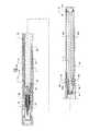
図8は、本発明の第2実施形態を表す図である。同図において、第1実施形態と同じ部材は同一の符号を付して、詳細説明を省略する。 FIG. 8 is a diagram illustrating a second embodiment of the present invention. In the figure, the same members as those in the first embodiment are denoted by the same reference numerals, and detailed description thereof is omitted.
第1実施形態では、チャックとして縦型のチャックを使用していたが、この実施形態では、C型のチャックを使用している点で異なっており、それ以外の点では、ほぼ同様である。 In the first embodiment, a vertical chuck is used as the chuck, but this embodiment is different in that a C-type chuck is used, and is otherwise substantially the same.
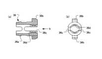
図10及び図11に示すように、C型のチャック38の後端に形成されて外径方向に突出する上下一対の突起38bが、カートリッジケース30の後端に形成された上下一対の切欠30bに嵌入されて係止される。また、チャック38の周面には、突起38bが形成されていない部分に軸方向に伸びる1本のスリット38cが形成されており、こうして、チャック38の横断面がC型形状をなしている。チャック38の後端部の内周面には、スリット38cが形成されていない部分に雌ネジ38dが形成されている。スリット38cが圧縮することでチャック38の雌ネジ38dは、径方向に縮径可能となる。スリット38cを含めたチャック38の輪郭は、円形に限らず、楕円であってもよい。 As shown in FIGS. 10 and 11, a pair of upper and
ピストンロッド17の雄ネジ17aとチャック38の雌ネジ38dとからなる螺合部が、ピストンロッド17を前進させる変換部を構成する。 The threaded portion formed by the
このようなチャック38を設けたカートリッジ16の場合にも、カートリッジ16を本体13に装填する際に(図9参照)、チャック38は本体13の小径部13bに挿入され、チャック38の突起38bは小径部13bによって押圧されてスリット38cを圧縮して、チャック38の内径は窄められて、チャック38は回転しながら、その雌ネジ38dがピストンロッド17の雄ネジ17aに螺合する(図8)。 Also in the case of the
また、反対に、カートリッジ16を交換する必要ができて、先具12と本体13との螺着を解き、先具12を回転していくと、カートリッジ16も回転しながら前進する。このとき、チャック38の雌ネジ38dは、ピストンロッド17の雄ネジ17aに対して回転するが、チャック38の突起38bが小径部13bから外れると、チャック36の後端部の内径が元の自然状態に復帰するため、もはや雌ネジ38dは雄ネジ17aに対して螺合せず、螺合は弛緩されて、ピストンロッド17は、カートリッジ16から解放されるため、スプリング18のスプリング力によって後方へと戻り、初期状態へと自動的に復帰する。 On the other hand, when the
こうして、第1実施形態と同様に作用させることができる。 In this way, it can be made to act similarly to the first embodiment.
図12は、本発明の第3実施形態を表す図である。同図において、第1実施形態と同じ部材は同一の符号を付して、詳細説明を省略する。 FIG. 12 is a diagram illustrating a third embodiment of the present invention. In the figure, the same members as those in the first embodiment are denoted by the same reference numerals, and detailed description thereof is omitted.
この実施形態では、操作体は本体の後端部に取付けられているのではなく、本体43の先端部に取付けられた先具42が操作体を兼ねている点で、前実施形態と異なっている。 In this embodiment, the operating body is not attached to the rear end portion of the main body, but differs from the previous embodiment in that the
即ち、先具42には、液体を塗布する為の先端塗布体である刷毛24と、液体を刷毛24に流出する先端パイプ26と、先具42内で固定され、且つ刷毛24及び先端パイプ26を先具42に固定するパイプホルダ28と、が設けられる。さらに、先具12の内周面には、パイプホルダ28よりも後方に複数の軸方向に伸びる縦リブ12a(図12参照)が形成されている。 That is, the
先具42の後端部は、本体43の先端部に挿入されて、着脱可能に嵌合される。嵌合後は、先具42と本体43とは相対回転可能に連結される。本体43の内部の中央部には、ストッパー44が固定されており、該ストッパー44の中心孔をピストンロッド17が貫通している。本体43内のストッパー44より前方の部分は、カートリッジ16が挿入される空間となる。ストッパー44よりも直前の本体43の部分は小径部43bとなっており、該小径部43bは、該小径部43bよりも前側の部分よりも内径が小さくなっている。また、本体43のストッパー44よりも後方の部分には、その内周面に、複数の軸方向に伸びる縦リブ43aが形成されており、該縦リブ43aの間に、ピストンロッド17の縦リブ17bが嵌合するようになっており、こうして、ピストンロッド17は、本体43と一体的に回転する。勿論、本体43内の内周面が多角形状となっており、ピストンロッド17の後端部がこれに嵌合する多角形状となっていてもよい。 The rear end portion of the
以上のように構成されるカートリッジ式液体繰り出し容器10において、その作用を説明する。まず、カートリッジ16は、本体43内に装填される。装填は、本体43と先具42との結合を解き、カートリッジケース30を先具42のパイプホルダ28に連結した後、本体43の開放された先端の開口からカートリッジ16を本体43内に挿入して、先具42を本体43に再び結合することにより、行う(図13参照)。このとき、カートリッジ16は、前記本体43内に固定されたストッパー44に当接するまで挿入される。カートリッジケース30に設けられたチャック36は本体43の小径部43bに挿入され、チャック36の突起36bは小径部43bによって押圧されて切欠36cを圧縮して、チャック36の後端部の内径は窄められる。そして、先具42及びチャック36を回転させながら、その雌ネジ36dをピストンロッド17の雄ネジ17aに螺合する。 The operation of the cartridge type
カートリッジ式液体繰り出し容器10を使用する際には、キャップ19を取り外して、刷毛24で所望の部分に液体を塗布することができる。また、刷毛24から供給される液体が少なくなった場合には、先具42を本体43に対して所定の方向に回転する。すると、先具42と一体的に回転するカートリッジ16が回転し、ピストンロッド17は本体43に対して回転不能であるため、ピストンロッド17はカートリッジ16のチャック36と螺合しながら本体43内を前進する。そうして、ピストンロッド17の先端部がピストン34の受凹部34aに嵌入して、ピストン34を前方へと押し出すので、タンク部32内の液体がパイプホルダ28を介して刷毛24へと押し出されて、刷毛24から被塗布面へと塗布される。 When using the cartridge type
こうして、液体の使用と共にピストンロッド17はカートリッジケース30内及び本体43内を前進して、ピストン34はタンク部32内を前進摺動していく。液体が使用されてタンク部32内の液体がなくなり、カートリッジ16を交換する必要がでると、再び、先具42と本体43との結合を解く。この結合を解く際に、先具42を回転しながら引き抜いていくと、カートリッジ16も回転しながら前進する。このとき、チャック36の雌ネジ36dは、ピストンロッド17の雄ネジ17aに対して回転するが、チャック36の突起36bが小径部43bから外れると、チャック36の後端部の内径が元の自然状態に復帰するため、もはや雌ネジ36dは雄ネジ17aに対して螺合せず、螺合は弛緩し、ピストンロッド17は、カートリッジ16から解放されるため、スプリング18のスプリング力によって後方へと戻り、初期状態へと自動的に復帰する。 Thus, the
そして、先具42と本体43が分離された後、古いカートリッジ16を先具42から外して、新たなカートリッジ16を先具42に連結して、再び、この新しいカートリッジ16を本体43に装填することにより、先と同様に使用することができるようになる。こうして、先具42、本体43等のカートリッジ以外の液体繰り出し容器10の部品を使い捨てにせずに、液体を補充または交換することができる。 Then, after the
また、カートリッジ16だけでなく、先具42を交換することもできる。例えば、液体の種類を変える場合には、先具42ごと交換すれば、刷毛24を含めて交換することができる。 Further, not only the
以上の各実施形態において、単一の部材で構成されていた部材を、複数部材で構成することも可能であり、逆に複数部材で構成された部材を単一の部材を構成することも可能である。 In each of the above-described embodiments, a member constituted by a single member can be constituted by a plurality of members, and conversely, a member constituted by a plurality of members can be constituted by a single member. It is.
10 カートリッジ式液体繰り出し容器
12 先具
13、43 本体
14 操作体
16 カートリッジ
17 ピストンロッド
17a 雄ネジ
24 刷毛(液体供給体)
30 カートリッジケース
34 ピストン
36、38 チャック
36d、38d 雌ネジ
42 先具(操作体)
DESCRIPTION OF
30
Claims (4)
Translated fromJapanese外部から操作可能となった操作体と、
前記本体に対して着脱可能に装填されて、カートリッジケース、カートリッジケース内にあって液体を収容するタンク部及びタンク部を摺動可能に移動するピストンを有するカートリッジと、
タンク部内の液体を外部へと供給する液体供給体と、
前記カートリッジのピストンを前方へと押圧するべく、ピストンに作用可能であり、前記カートリッジケース内及び本体内を移動可能となったピストンロッドと、
前記操作体に付加された操作力を、ピストンロッドの前進に変換する変換部と、
を備え、
当該変換部は、ピストンロッドとカートリッジケースとの間に形成されてピストンロッドとカートリッジケースとを螺合させる螺合部であり、
当該螺合部は、前記ピストンロッドの外周面に形成された雄ネジと、カートリッジケースに設けられたC型チャックの内周面に形成された雌ネジと、からなり、当該C型チャックは、周面に軸方向に伸びる1本のスリットが形成されて横断面がC型形状をなし、径方向に拡縮可能であり、本体内の取付位置にあるときに、縮径されて雌ネジがピストンロッドの雄ネジと螺合し、操作体と本体との間の相対回転により、前記螺合部がピストンロッドを前進させることを特徴とするカートリッジ式液体繰り出し容器。The body,
An operating body that can be operated from outside,
A cartridge case that is detachably loaded with respect to the main body, and has a cartridge part, a tank part in the cartridge case, and a piston that slidably moves in the tank part;
A liquid supply body for supplying the liquid in the tank portion to the outside;
A piston rod which can act on the piston to move the piston of the cartridge forward, and is movable in the cartridge case and the main body;
A converter that converts the operating force applied to the operating body into a forward movement of the piston rod;
Equipped witha,
The conversion part is a screwing part that is formed between the piston rod and the cartridge case to screw the piston rod and the cartridge case,
The threaded portion includes a male screw formed on the outer peripheral surface of the piston rod and a female screw formed on the inner peripheral surface of a C-type chuck provided in the cartridge case. One slit extending in the axial direction is formed on the peripheral surface, the cross section is C-shaped, and can be expanded or contracted in the radial direction. A cartridge-type liquid feeding container,wherein the cartridge-type liquid feeding containeris screwed with a male screw of a rod, and the screwing portion advances a piston rod by relative rotation between an operating body and a main body .
前記螺合部は、カートリッジが本体内の取付位置にあるときに、ピストンロッドとC型チャックとを螺合させる一方で、本体内の取付位置から外れると、ピストンロッドとC型チャックとの螺合を弛緩させることを特徴とする請求項1記載のカートリッジ式液体繰り出し容器。The piston rod is urged in the direction away from the cartridge in the main body,
The screwing portion screwes the piston rod and theC-shaped chuck when the cartridge is at the mounting position in the main body, and on the other hand, when the cartridge is detached from the mounting position in the main body, the screwing between the piston rod and theC-shaped chuck is performed. cartridge liquid feeding container according to claim1, wherein the to relax engagement.
Priority Applications (6)
| Application Number | Priority Date | Filing Date | Title |
|---|---|---|---|
| JP2004012326AJP4335701B2 (en) | 2004-01-20 | 2004-01-20 | Cartridge type liquid feeding container |
| TW093114899ATW200524552A (en) | 2004-01-20 | 2004-05-26 | Cartridge-type liquid propelling container |
| KR1020040040963AKR100605082B1 (en) | 2004-01-20 | 2004-06-04 | Cartridge-type liquid propelling container |
| CNA2004100634802ACN1644468A (en) | 2004-01-20 | 2004-07-06 | Cartridge type liquid feeding container |
| EP04254216.7AEP1557288B1 (en) | 2004-01-20 | 2004-07-14 | Cartridge type liquid feeding container |
| US10/896,016US7237975B2 (en) | 2004-01-20 | 2004-07-22 | Cartridge type liquid feeding container |
Applications Claiming Priority (1)
| Application Number | Priority Date | Filing Date | Title |
|---|---|---|---|
| JP2004012326AJP4335701B2 (en) | 2004-01-20 | 2004-01-20 | Cartridge type liquid feeding container |
Publications (2)
| Publication Number | Publication Date |
|---|---|
| JP2005206165A JP2005206165A (en) | 2005-08-04 |
| JP4335701B2true JP4335701B2 (en) | 2009-09-30 |
Family
ID=34631889
Family Applications (1)
| Application Number | Title | Priority Date | Filing Date |
|---|---|---|---|
| JP2004012326AExpired - LifetimeJP4335701B2 (en) | 2004-01-20 | 2004-01-20 | Cartridge type liquid feeding container |
Country Status (6)
| Country | Link |
|---|---|
| US (1) | US7237975B2 (en) |
| EP (1) | EP1557288B1 (en) |
| JP (1) | JP4335701B2 (en) |
| KR (1) | KR100605082B1 (en) |
| CN (1) | CN1644468A (en) |
| TW (1) | TW200524552A (en) |
Families Citing this family (26)
| Publication number | Priority date | Publication date | Assignee | Title |
|---|---|---|---|---|
| US7607852B2 (en)* | 2006-03-02 | 2009-10-27 | Washington Pamela D | Liquids applicator |
| JP5373418B2 (en)* | 2009-02-04 | 2013-12-18 | 株式会社ヒダン | Cartridge type cosmetic container |
| BR112012005250A2 (en) | 2009-09-16 | 2019-09-24 | Colgate Palmolive Co | oral care system, combined oral care dispenser and toothbrush, and methods for applying oral care material to an oral surface and teeth |
| CN102049947A (en)* | 2009-11-02 | 2011-05-11 | 王华伍 | Metering correction pen |
| PH12012500882A1 (en) | 2009-12-23 | 2013-01-07 | Colgate Palmolive Co | Oral care system, kit and method |
| RU2525808C2 (en) | 2009-12-23 | 2014-08-20 | Колгейт-Палмолив Компани | Oral care system |
| KR101513342B1 (en) | 2009-12-23 | 2015-04-17 | 콜게이트-파아므올리브캄파니 | Oral care system |
| WO2011078863A1 (en) | 2009-12-23 | 2011-06-30 | Colgate-Palmolive Company | Oral care system |
| WO2012082183A1 (en) | 2010-12-15 | 2012-06-21 | Colgate-Palmolive Company | Oral care dispenser |
| JP5484143B2 (en)* | 2010-03-23 | 2014-05-07 | 三菱鉛筆株式会社 | Knock-type applicator |
| CN102821971B (en)* | 2010-03-23 | 2015-08-12 | 三菱铅笔株式会社 | Click Applicator |
| JP5545635B2 (en)* | 2010-03-23 | 2014-07-09 | 三菱鉛筆株式会社 | Applicator |
| JP5592306B2 (en)* | 2011-05-11 | 2014-09-17 | 株式会社トキワ | Stick-shaped cosmetic supply container |
| DE102011116762B4 (en)* | 2011-10-21 | 2017-03-09 | Montblanc-Simplo Gmbh | writing implement |
| CN103653684A (en)* | 2013-12-06 | 2014-03-26 | 南通宝田包装科技有限公司 | Detachable and multifunctional cosmetic tube |
| CN105361403B (en)* | 2014-08-26 | 2018-06-15 | 洽兴包装工业(中国)有限公司 | Replaceable cosmetic pencil |
| US10427859B2 (en)* | 2014-10-24 | 2019-10-01 | Conopco, Inc. | Dispenser for a cream, gel or soft solid composition |
| AU2015381790B2 (en) | 2015-02-02 | 2018-10-04 | Colgate-Palmolive Company | Oral care system and oral care material dispenser |
| CN105249659A (en)* | 2015-10-15 | 2016-01-20 | 锦奈化妆品(上海)有限公司 | Cream bottle |
| GB2586073B (en)* | 2019-08-02 | 2021-08-25 | Dongguan Xingwan Ind Development Co Ltd | Eyeliner |
| FR3104392B1 (en) | 2019-12-16 | 2021-12-24 | Oreal | Cosmetic product refill, intended to be removably mounted in a trim band, loading assembly, kit, device and associated mounting method |
| FR3104390B1 (en) | 2019-12-16 | 2021-12-24 | Oreal | Cosmetic product refill, charging assembly, dispensing mechanism and related kit |
| FR3104391B1 (en) | 2019-12-16 | 2021-12-24 | Oreal | Loading assembly intended for a cosmetic product packaging and dispensing device, kit and associated method |
| JP7351741B2 (en)* | 2019-12-23 | 2023-09-27 | 株式会社 資生堂 | Cosmetic dispensing container |
| FR3110898B1 (en)* | 2020-05-27 | 2024-03-15 | Coradin Sas | ASSEMBLY COMPOSED OF A CONTAINER FOR A FLUID AND A DISPENSER PACKAGING |
| JP2025528249A (en) | 2022-08-25 | 2025-08-26 | サノフイ | Novel substituted quinoline and tetrahydronaphthalenecarboxylic acid derivatives and their therapeutic uses |
Family Cites Families (15)
| Publication number | Priority date | Publication date | Assignee | Title |
|---|---|---|---|---|
| US2632193A (en)* | 1947-10-02 | 1953-03-24 | Neergaard And Associates | Ball applicator type dispenser with lockable ball and removable cartridge |
| US3002517A (en)* | 1959-12-08 | 1961-10-03 | Eva V Pitton | Cosmetic applicator with replaceable cartridge |
| US3359992A (en)* | 1964-11-06 | 1967-12-26 | Avon Prod Inc | Cosmetic applicator |
| US3468612A (en)* | 1965-10-23 | 1969-09-23 | Bruno D Aston | Cosmetic applicator case and replaceable cartridge therefor |
| US4599008A (en)* | 1985-06-28 | 1986-07-08 | Fin-Tech Limited Partnership | Fingernail polish capsule and plunger |
| DE3688719T2 (en)* | 1985-07-11 | 1993-11-04 | Yoshino Kogyosho Co Ltd | CONTAINER-LIKE TOILET DEVICE. |
| JPS63152685U (en)* | 1987-03-24 | 1988-10-06 | ||
| JP3352115B2 (en) | 1992-07-01 | 2002-12-03 | タカラベルモント株式会社 | Rotation control device for shampoo ball |
| JPH0614844U (en) | 1992-07-17 | 1994-02-25 | 輝男 高橋 | Humidifier with sensor |
| US6213662B1 (en)* | 1999-05-13 | 2001-04-10 | Mohdsameer Y Aljanedi | Toothbrush with paste dispenser |
| KR200197728Y1 (en) | 2000-04-19 | 2000-09-15 | 김명언 | Marker pen with ink refilling function |
| JP3519668B2 (en) | 2000-04-21 | 2004-04-19 | 株式会社壽 | Liquid container |
| FR2812277B1 (en)* | 2000-07-27 | 2003-01-10 | Oreal | DEVICE FOR PACKAGING AND APPLYING A PRODUCT, ESPECIALLY COSMETIC |
| US6328040B1 (en)* | 2000-08-02 | 2001-12-11 | Julie Anne Stein | Nail polish pen having spare tips |
| KR100444387B1 (en) | 2001-08-16 | 2004-08-16 | 안석두 | Liquid Lib Pencil |
- 2004
- 2004-01-20JPJP2004012326Apatent/JP4335701B2/ennot_activeExpired - Lifetime
- 2004-05-26TWTW093114899Apatent/TW200524552A/enunknown
- 2004-06-04KRKR1020040040963Apatent/KR100605082B1/ennot_activeExpired - Fee Related
- 2004-07-06CNCNA2004100634802Apatent/CN1644468A/enactivePending
- 2004-07-14EPEP04254216.7Apatent/EP1557288B1/ennot_activeExpired - Lifetime
- 2004-07-22USUS10/896,016patent/US7237975B2/ennot_activeExpired - Lifetime
Also Published As
| Publication number | Publication date |
|---|---|
| EP1557288B1 (en) | 2013-04-17 |
| US20050158114A1 (en) | 2005-07-21 |
| JP2005206165A (en) | 2005-08-04 |
| CN1644468A (en) | 2005-07-27 |
| EP1557288A3 (en) | 2006-12-06 |
| KR100605082B1 (en) | 2006-07-31 |
| US7237975B2 (en) | 2007-07-03 |
| EP1557288A2 (en) | 2005-07-27 |
| KR20050076575A (en) | 2005-07-26 |
| TW200524552A (en) | 2005-08-01 |
Similar Documents
| Publication | Publication Date | Title |
|---|---|---|
| JP4335701B2 (en) | Cartridge type liquid feeding container | |
| US7217054B2 (en) | Side knock type feeding mechanism | |
| JP3636629B2 (en) | Cartridge type feeding container | |
| JP2010125715A (en) | Liquid feeding implement | |
| KR20160040515A (en) | Liquid applying tool | |
| JP4509577B2 (en) | Liquid container | |
| KR101579643B1 (en) | Click-type applicator | |
| JP5325593B2 (en) | Cartridge type cosmetic container | |
| JP7348658B2 (en) | Cosmetic dispensing container | |
| JP7394199B2 (en) | cosmetic applicator | |
| CN115474759B (en) | The stick is screwed out of the container | |
| JP4480343B2 (en) | Cartridge type applicator | |
| CN113116045B (en) | Cosmetic material delivery container | |
| JP5484143B2 (en) | Knock-type applicator | |
| JP6361011B2 (en) | Cartridge-type contents extrusion container | |
| JP2010193919A (en) | Push type liquid dispensing container | |
| JPH0621585Y2 (en) | Applicator | |
| JP2005053038A (en) | Rotational delivery type writing utensil | |
| JP6318344B2 (en) | Cartridge-type contents extrusion container | |
| JP3981194B2 (en) | Bar-shaped material replenishment cassette and bar-shaped material feeding container | |
| JP5234596B2 (en) | Knock-type feeding container | |
| JPH0317781Y2 (en) | ||
| JP2024012102A (en) | writing implements | |
| JP2545213Y2 (en) | Cartridge type solid cosmetic dispensing container | |
| JP2015016624A (en) | Inner core storage body for writing instrument |
Legal Events
| Date | Code | Title | Description |
|---|---|---|---|
| A621 | Written request for application examination | Free format text:JAPANESE INTERMEDIATE CODE: A621 Effective date:20061226 | |
| A977 | Report on retrieval | Free format text:JAPANESE INTERMEDIATE CODE: A971007 Effective date:20090302 | |
| A131 | Notification of reasons for refusal | Free format text:JAPANESE INTERMEDIATE CODE: A131 Effective date:20090407 | |
| A521 | Request for written amendment filed | Free format text:JAPANESE INTERMEDIATE CODE: A523 Effective date:20090608 | |
| TRDD | Decision of grant or rejection written | ||
| A01 | Written decision to grant a patent or to grant a registration (utility model) | Free format text:JAPANESE INTERMEDIATE CODE: A01 Effective date:20090623 | |
| A01 | Written decision to grant a patent or to grant a registration (utility model) | Free format text:JAPANESE INTERMEDIATE CODE: A01 | |
| A61 | First payment of annual fees (during grant procedure) | Free format text:JAPANESE INTERMEDIATE CODE: A61 Effective date:20090625 | |
| FPAY | Renewal fee payment (event date is renewal date of database) | Free format text:PAYMENT UNTIL: 20120703 Year of fee payment:3 | |
| R150 | Certificate of patent or registration of utility model | Ref document number:4335701 Country of ref document:JP Free format text:JAPANESE INTERMEDIATE CODE: R150 Free format text:JAPANESE INTERMEDIATE CODE: R150 | |
| FPAY | Renewal fee payment (event date is renewal date of database) | Free format text:PAYMENT UNTIL: 20120703 Year of fee payment:3 | |
| FPAY | Renewal fee payment (event date is renewal date of database) | Free format text:PAYMENT UNTIL: 20120703 Year of fee payment:3 | |
| FPAY | Renewal fee payment (event date is renewal date of database) | Free format text:PAYMENT UNTIL: 20150703 Year of fee payment:6 | |
| R250 | Receipt of annual fees | Free format text:JAPANESE INTERMEDIATE CODE: R250 | |
| R250 | Receipt of annual fees | Free format text:JAPANESE INTERMEDIATE CODE: R250 | |
| R250 | Receipt of annual fees | Free format text:JAPANESE INTERMEDIATE CODE: R250 | |
| R250 | Receipt of annual fees | Free format text:JAPANESE INTERMEDIATE CODE: R250 | |
| R250 | Receipt of annual fees | Free format text:JAPANESE INTERMEDIATE CODE: R250 | |
| EXPY | Cancellation because of completion of term |