JP4334022B2 - Method and apparatus for occluding a patient's ascending aorta - Google Patents
Method and apparatus for occluding a patient's ascending aortaDownload PDFInfo
- Publication number
- JP4334022B2 JP4334022B2JP54195598AJP54195598AJP4334022B2JP 4334022 B2JP4334022 B2JP 4334022B2JP 54195598 AJP54195598 AJP 54195598AJP 54195598 AJP54195598 AJP 54195598AJP 4334022 B2JP4334022 B2JP 4334022B2
- Authority
- JP
- Japan
- Prior art keywords
- patient
- blood
- catheter
- pressure
- tube
- Prior art date
- Legal status (The legal status is an assumption and is not a legal conclusion. Google has not performed a legal analysis and makes no representation as to the accuracy of the status listed.)
- Expired - Lifetime
Links
- 210000000709aortaAnatomy0.000titleclaimsabstractdescription18
- 238000000034methodMethods0.000titledescription16
- 239000008280bloodSubstances0.000claimsabstractdescription49
- 210000004369bloodAnatomy0.000claimsabstractdescription49
- 230000017531blood circulationEffects0.000claimsdescription9
- 230000001590oxidative effectEffects0.000claimsdescription8
- 239000012530fluidSubstances0.000claimsdescription7
- 206010058178Aortic occlusionDiseases0.000abstractdescription39
- 210000001367arteryAnatomy0.000description22
- 210000001765aortic valveAnatomy0.000description11
- 238000001356surgical procedureMethods0.000description9
- 210000001715carotid arteryAnatomy0.000description7
- 210000003748coronary sinusAnatomy0.000description7
- 230000003014reinforcing effectEffects0.000description6
- 210000003270subclavian arteryAnatomy0.000description6
- 210000004191axillary arteryAnatomy0.000description5
- 239000000463materialSubstances0.000description5
- 206010020772HypertensionDiseases0.000description4
- 239000011248coating agentSubstances0.000description4
- 238000000576coating methodMethods0.000description4
- 230000035515penetrationEffects0.000description4
- 238000009423ventilationMethods0.000description4
- 241001631457CannulaSpecies0.000description3
- 208000010496Heart ArrestDiseases0.000description3
- 230000036772blood pressureEffects0.000description3
- 229940100084cardioplegia solutionDrugs0.000description3
- 210000004351coronary vesselAnatomy0.000description3
- 238000004519manufacturing processMethods0.000description3
- 229920002635polyurethanePolymers0.000description3
- 239000004814polyurethaneSubstances0.000description3
- 210000005166vasculatureAnatomy0.000description3
- 210000002376aorta thoracicAnatomy0.000description2
- 238000001125extrusionMethods0.000description2
- 238000002594fluoroscopyMethods0.000description2
- 238000010438heat treatmentMethods0.000description2
- 238000002347injectionMethods0.000description2
- 239000007924injectionSubstances0.000description2
- 239000007800oxidant agentSubstances0.000description2
- 210000005245right atriumAnatomy0.000description2
- HTTJABKRGRZYRN-UHFFFAOYSA-NHeparinChemical compoundOC1C(NC(=O)C)C(O)OC(COS(O)(=O)=O)C1OC1C(OS(O)(=O)=O)C(O)C(OC2C(C(OS(O)(=O)=O)C(OC3C(C(O)C(O)C(O3)C(O)=O)OS(O)(=O)=O)C(CO)O2)NS(O)(=O)=O)C(C(O)=O)O1HTTJABKRGRZYRN-UHFFFAOYSA-N0.000description1
- 208000001953HypotensionDiseases0.000description1
- FAPWRFPIFSIZLT-UHFFFAOYSA-MSodium chlorideChemical compound[Na+].[Cl-]FAPWRFPIFSIZLT-UHFFFAOYSA-M0.000description1
- 208000007536ThrombosisDiseases0.000description1
- 230000001174ascending effectEffects0.000description1
- 230000001746atrial effectEffects0.000description1
- 229960001716benzalkoniumDrugs0.000description1
- CYDRXTMLKJDRQH-UHFFFAOYSA-NbenzododeciniumChemical compoundCCCCCCCCCCCC[N+](C)(C)CC1=CC=CC=C1CYDRXTMLKJDRQH-UHFFFAOYSA-N0.000description1
- 230000036770blood supplyEffects0.000description1
- 210000004204blood vesselAnatomy0.000description1
- 210000002302brachial arteryAnatomy0.000description1
- 210000004556brainAnatomy0.000description1
- 230000000747cardiac effectEffects0.000description1
- 238000007675cardiac surgeryMethods0.000description1
- 230000001101cardioplegic effectEffects0.000description1
- 230000004087circulationEffects0.000description1
- 238000010276constructionMethods0.000description1
- 230000008878couplingEffects0.000description1
- 238000010168coupling processMethods0.000description1
- 238000005859coupling reactionMethods0.000description1
- 210000003191femoral veinAnatomy0.000description1
- 229960002897heparinDrugs0.000description1
- 229920000669heparinPolymers0.000description1
- 210000004731jugular veinAnatomy0.000description1
- 208000012866low blood pressureDiseases0.000description1
- 210000004072lungAnatomy0.000description1
- 239000000203mixtureSubstances0.000description1
- 238000012544monitoring processMethods0.000description1
- 230000002093peripheral effectEffects0.000description1
- 235000013855polyvinylpyrrolidoneNutrition0.000description1
- 229920000036polyvinylpyrrolidonePolymers0.000description1
- 239000001267polyvinylpyrrolidoneSubstances0.000description1
- 210000001147pulmonary arteryAnatomy0.000description1
- 230000002685pulmonary effectEffects0.000description1
- 238000005086pumpingMethods0.000description1
- 230000002787reinforcementEffects0.000description1
- 239000011780sodium chlorideSubstances0.000description1
- 229910001220stainless steelInorganic materials0.000description1
- 239000010935stainless steelSubstances0.000description1
- 238000011144upstream manufacturingMethods0.000description1
- 210000003462veinAnatomy0.000description1
Images


Classifications
- A—HUMAN NECESSITIES
- A61—MEDICAL OR VETERINARY SCIENCE; HYGIENE
- A61M—DEVICES FOR INTRODUCING MEDIA INTO, OR ONTO, THE BODY; DEVICES FOR TRANSDUCING BODY MEDIA OR FOR TAKING MEDIA FROM THE BODY; DEVICES FOR PRODUCING OR ENDING SLEEP OR STUPOR
- A61M25/00—Catheters; Hollow probes
- A61M25/0021—Catheters; Hollow probes characterised by the form of the tubing
- A61M25/0023—Catheters; Hollow probes characterised by the form of the tubing by the form of the lumen, e.g. cross-section, variable diameter
- A—HUMAN NECESSITIES
- A61—MEDICAL OR VETERINARY SCIENCE; HYGIENE
- A61B—DIAGNOSIS; SURGERY; IDENTIFICATION
- A61B17/00—Surgical instruments, devices or methods
- A61B17/12—Surgical instruments, devices or methods for ligaturing or otherwise compressing tubular parts of the body, e.g. blood vessels or umbilical cord
- A61B17/12022—Occluding by internal devices, e.g. balloons or releasable wires
- A61B17/12099—Occluding by internal devices, e.g. balloons or releasable wires characterised by the location of the occluder
- A61B17/12109—Occluding by internal devices, e.g. balloons or releasable wires characterised by the location of the occluder in a blood vessel
- A—HUMAN NECESSITIES
- A61—MEDICAL OR VETERINARY SCIENCE; HYGIENE
- A61B—DIAGNOSIS; SURGERY; IDENTIFICATION
- A61B17/00—Surgical instruments, devices or methods
- A61B17/12—Surgical instruments, devices or methods for ligaturing or otherwise compressing tubular parts of the body, e.g. blood vessels or umbilical cord
- A61B17/12022—Occluding by internal devices, e.g. balloons or releasable wires
- A61B17/12131—Occluding by internal devices, e.g. balloons or releasable wires characterised by the type of occluding device
- A61B17/12136—Balloons
- A—HUMAN NECESSITIES
- A61—MEDICAL OR VETERINARY SCIENCE; HYGIENE
- A61M—DEVICES FOR INTRODUCING MEDIA INTO, OR ONTO, THE BODY; DEVICES FOR TRANSDUCING BODY MEDIA OR FOR TAKING MEDIA FROM THE BODY; DEVICES FOR PRODUCING OR ENDING SLEEP OR STUPOR
- A61M25/00—Catheters; Hollow probes
- A61M25/0043—Catheters; Hollow probes characterised by structural features
- A—HUMAN NECESSITIES
- A61—MEDICAL OR VETERINARY SCIENCE; HYGIENE
- A61M—DEVICES FOR INTRODUCING MEDIA INTO, OR ONTO, THE BODY; DEVICES FOR TRANSDUCING BODY MEDIA OR FOR TAKING MEDIA FROM THE BODY; DEVICES FOR PRODUCING OR ENDING SLEEP OR STUPOR
- A61M25/00—Catheters; Hollow probes
- A61M2025/0001—Catheters; Hollow probes for pressure measurement
- A61M2025/0002—Catheters; Hollow probes for pressure measurement with a pressure sensor at the distal end
- A—HUMAN NECESSITIES
- A61—MEDICAL OR VETERINARY SCIENCE; HYGIENE
- A61M—DEVICES FOR INTRODUCING MEDIA INTO, OR ONTO, THE BODY; DEVICES FOR TRANSDUCING BODY MEDIA OR FOR TAKING MEDIA FROM THE BODY; DEVICES FOR PRODUCING OR ENDING SLEEP OR STUPOR
- A61M25/00—Catheters; Hollow probes
- A61M25/0021—Catheters; Hollow probes characterised by the form of the tubing
- A61M25/0023—Catheters; Hollow probes characterised by the form of the tubing by the form of the lumen, e.g. cross-section, variable diameter
- A61M25/0026—Multi-lumen catheters with stationary elements
- A61M25/003—Multi-lumen catheters with stationary elements characterized by features relating to least one lumen located at the distal part of the catheter, e.g. filters, plugs or valves
- A61M2025/0031—Multi-lumen catheters with stationary elements characterized by features relating to least one lumen located at the distal part of the catheter, e.g. filters, plugs or valves characterized by lumina for withdrawing or delivering, i.e. used for extracorporeal circuit treatment
- A—HUMAN NECESSITIES
- A61—MEDICAL OR VETERINARY SCIENCE; HYGIENE
- A61M—DEVICES FOR INTRODUCING MEDIA INTO, OR ONTO, THE BODY; DEVICES FOR TRANSDUCING BODY MEDIA OR FOR TAKING MEDIA FROM THE BODY; DEVICES FOR PRODUCING OR ENDING SLEEP OR STUPOR
- A61M25/00—Catheters; Hollow probes
- A61M25/0021—Catheters; Hollow probes characterised by the form of the tubing
- A61M25/0023—Catheters; Hollow probes characterised by the form of the tubing by the form of the lumen, e.g. cross-section, variable diameter
- A61M25/0026—Multi-lumen catheters with stationary elements
- A61M2025/0034—Multi-lumen catheters with stationary elements characterized by elements which are assembled, connected or fused, e.g. splittable tubes, outer sheaths creating lumina or separate cores
- A—HUMAN NECESSITIES
- A61—MEDICAL OR VETERINARY SCIENCE; HYGIENE
- A61M—DEVICES FOR INTRODUCING MEDIA INTO, OR ONTO, THE BODY; DEVICES FOR TRANSDUCING BODY MEDIA OR FOR TAKING MEDIA FROM THE BODY; DEVICES FOR PRODUCING OR ENDING SLEEP OR STUPOR
- A61M25/00—Catheters; Hollow probes
- A61M25/10—Balloon catheters
- A61M2025/1043—Balloon catheters with special features or adapted for special applications
- A61M2025/1052—Balloon catheters with special features or adapted for special applications for temporarily occluding a vessel for isolating a sector
- A—HUMAN NECESSITIES
- A61—MEDICAL OR VETERINARY SCIENCE; HYGIENE
- A61M—DEVICES FOR INTRODUCING MEDIA INTO, OR ONTO, THE BODY; DEVICES FOR TRANSDUCING BODY MEDIA OR FOR TAKING MEDIA FROM THE BODY; DEVICES FOR PRODUCING OR ENDING SLEEP OR STUPOR
- A61M2210/00—Anatomical parts of the body
- A61M2210/12—Blood circulatory system
- A61M2210/127—Aorta
- A—HUMAN NECESSITIES
- A61—MEDICAL OR VETERINARY SCIENCE; HYGIENE
- A61M—DEVICES FOR INTRODUCING MEDIA INTO, OR ONTO, THE BODY; DEVICES FOR TRANSDUCING BODY MEDIA OR FOR TAKING MEDIA FROM THE BODY; DEVICES FOR PRODUCING OR ENDING SLEEP OR STUPOR
- A61M25/00—Catheters; Hollow probes
- A61M25/0009—Making of catheters or other medical or surgical tubes
- A—HUMAN NECESSITIES
- A61—MEDICAL OR VETERINARY SCIENCE; HYGIENE
- A61M—DEVICES FOR INTRODUCING MEDIA INTO, OR ONTO, THE BODY; DEVICES FOR TRANSDUCING BODY MEDIA OR FOR TAKING MEDIA FROM THE BODY; DEVICES FOR PRODUCING OR ENDING SLEEP OR STUPOR
- A61M25/00—Catheters; Hollow probes
- A61M25/0021—Catheters; Hollow probes characterised by the form of the tubing
- A61M25/0023—Catheters; Hollow probes characterised by the form of the tubing by the form of the lumen, e.g. cross-section, variable diameter
- A61M25/0026—Multi-lumen catheters with stationary elements
- A61M25/0032—Multi-lumen catheters with stationary elements characterized by at least one unconventionally shaped lumen, e.g. polygons, ellipsoids, wedges or shapes comprising concave and convex parts
- A—HUMAN NECESSITIES
- A61—MEDICAL OR VETERINARY SCIENCE; HYGIENE
- A61M—DEVICES FOR INTRODUCING MEDIA INTO, OR ONTO, THE BODY; DEVICES FOR TRANSDUCING BODY MEDIA OR FOR TAKING MEDIA FROM THE BODY; DEVICES FOR PRODUCING OR ENDING SLEEP OR STUPOR
- A61M25/00—Catheters; Hollow probes
- A61M25/0043—Catheters; Hollow probes characterised by structural features
- A61M25/005—Catheters; Hollow probes characterised by structural features with embedded materials for reinforcement, e.g. wires, coils, braids
- A—HUMAN NECESSITIES
- A61—MEDICAL OR VETERINARY SCIENCE; HYGIENE
- A61M—DEVICES FOR INTRODUCING MEDIA INTO, OR ONTO, THE BODY; DEVICES FOR TRANSDUCING BODY MEDIA OR FOR TAKING MEDIA FROM THE BODY; DEVICES FOR PRODUCING OR ENDING SLEEP OR STUPOR
- A61M25/00—Catheters; Hollow probes
- A61M25/10—Balloon catheters
- A61M25/1002—Balloon catheters characterised by balloon shape
Landscapes
- Health & Medical Sciences (AREA)
- Life Sciences & Earth Sciences (AREA)
- Surgery (AREA)
- Veterinary Medicine (AREA)
- Public Health (AREA)
- General Health & Medical Sciences (AREA)
- Engineering & Computer Science (AREA)
- Biomedical Technology (AREA)
- Heart & Thoracic Surgery (AREA)
- Animal Behavior & Ethology (AREA)
- Molecular Biology (AREA)
- Medical Informatics (AREA)
- Nuclear Medicine, Radiotherapy & Molecular Imaging (AREA)
- Vascular Medicine (AREA)
- Reproductive Health (AREA)
- Biophysics (AREA)
- Pulmonology (AREA)
- Anesthesiology (AREA)
- Hematology (AREA)
- Media Introduction/Drainage Providing Device (AREA)
- Prostheses (AREA)
- Electrotherapy Devices (AREA)
Abstract
Description
Translated fromJapanese発明の背景
本発明は、患者がバイパスシステムにより維持されるときに、患者の上行大動脈を閉塞しかつ酸化血を患者に戻す方法および装置に関する。本発明は、心臓および大血管に手術を行なうときに特に有効である。
慣用的な開心術では、胸骨正中切開のように、患者の胸部に大きな切開を介して患者の心臓にアクセスする。患者の心臓が露出されたならば、種々のカテーテル、カニューレおよびクランプが患者の心臓および大血管に直接適用される。血液は、静脈カニューレを介して患者から吸引されかつ動脈戻しカニューレ(該動脈戻しカニューレは、一般に、上行大動脈の巾着縫合を介して挿入される)を介して患者に戻される。心臓は、針を用いて心停止液を上行大動脈内に注入することにより停止される。上行大動脈は、一般に、上行大動脈の回りに適用される外部クロスクランプにより閉塞され、冠状動脈を残余の動脈系から隔絶する。
心臓手術における最近の進歩により、患者の心臓に直接アクセスする必要なくして、患者の上行大動脈を閉塞し、酸化血を患者に戻しかつ心停止液を患者に供給できるカニューレおよびカテーテルが提供されている。このようなシステムは米国特許第5,584,803号、第5,478,309号および再発行特許第35,352号に開示されている。これらの特許に開示された装置および方法は、外科医が、患者の胸部を大きく切開する必要なくして、バイパス移植および弁交換等の種々の手術を患者の心臓および大血管に施すことを可能にする。このような手術は、伝統的な開心術に比べ、患者が受ける痛みおよび損傷を軽減できる。
上記米国特許第5,584,803号、第5,478,309号および再発行特許第35,352号に開示された他の長所は、大動脈の回りに外部クランプを適用するのではなく、大動脈内にバルーンを配置することにより大動脈の閉塞が行なえることである。バルーンを用いて上行大動脈を閉塞することにより、外部クロスクランプに比べ血流中に放出される血栓の量が低減される。
上記システムは、停止した心臓に広範囲の手術を施すことができるが、大動脈閉塞バルーンの配置は、大動脈弁と上腕頭動脈(brachiocephalic artery)との間の比較的小さい空間内にバルーンを位置決めしなければならないことから、しばしば挑戦的なものとなる。上腕頭動脈が不意に閉塞されるようなことがあると、右頸動脈(該頸動脈は上腕頭動脈から分岐しており、患者の脳に血液を供給する)に酸化血が供給されなくなるため危険である。大動脈弁手術を行なう場合には、バルーンの配置は特に挑戦的なものとなる。なぜならば、外科医がバルーンにより妨げられることなく大動脈弁手術を遂行できるようにするには、バルーンを大動脈弁から充分離れた位置に配置しなければならないからである。
従って本発明の目的は、患者の上腕頭動脈内に容易に配置できる閉塞部材を備えた大動脈閉塞カテーテルを提供することにある。
発明の概要
本発明は、患者の上腕頭動脈を閉塞しかつ酸化血をバイパスシステムから患者に供給する方法および大動脈閉塞カテーテルを提供する。大動脈閉塞カテーテルは、患者の動脈系内への穿通により挿入されかつ上腕頭動脈と上行大動脈との間の結合部に通される。好ましい実施形態では、大動脈閉塞カテーテルは、患者の腋窩動脈または鎖骨下動脈への穿通を介して患者の動脈系に入るのが好ましい。
大動脈閉塞カテーテルは、上行大動脈内に配置されかつ患者の上行大動脈を閉塞すべく拡大されて冠状動脈を患者の残余の動脈から隔絶する閉塞部材を有している。閉塞部材(好ましくはバルーン)は、閉塞部材の近位端と遠位端との間の部分に沿ってカテーテルシャフトに取り付けらるのが好ましい。閉塞部材が拡大されるとき、閉塞部材はシャフトの一方の側に拡大される。好ましい実施形態では、閉塞部材の拡大側は、大動脈弁に向かって拡大するように位置決めされる。
大動脈閉塞カテーテルはまた、酸化血を患者に戻すための第1および第2開口を備えた血流管孔を有している。第1および第2開口は閉塞部材の両側に配置されており、これにより、酸化血が閉塞部材の両側に供給される。開口の1つが、酸化血を、上腕頭動脈と大動脈弓との結合部より上流側で動脈に供給し、一方、他の開口が酸化血を身体の残部に供給する。閉塞部材の両側に開口を設けることの長所は、上腕頭動脈の閉塞によっても、酸化血が閉塞部材の両側に供給されるので患者に危険を与えないことである。大動脈閉塞カテーテルの他の長所は、閉塞部材を大動脈弁から離れた位置に容易に位置決めでき、これにより、大動脈弁手術を遂行する作業空間を最大化できることである。
また、大動脈閉塞カテーテルは、好ましくは、閉塞部材の両側の圧力を測定するための2つの圧力管孔を有している。2つの圧力管孔を設けるのが好ましいが、必須なのは1つの圧力管孔だけである。圧力管孔は、閉塞部材の両側の血圧を測定する圧力モニタに連結される。圧力モニタは、過度に高いまたは低い血圧(特に、頸動脈の過度に高い血圧)を防止するのに使用される。
上記および他の特徴は、好ましい実施形態の以下の説明から明らかになるであろう。
【図面の簡単な説明】
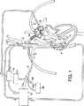
第1図は、患者の心臓および血管系の部分断面図であり、バイパスシステムと組み合わせられた本発明の大動脈閉塞カテーテルを示すものである。
第2図は、第1図の大動脈閉塞カテーテルを示す拡大図である。
第3図は、第1図および第2図の大動脈閉塞カテーテルを示す側面図である。
第4図は、第3図のA−A線に沿う断面図である。
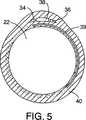
第5図は、他の大動脈閉塞カテーテルを示す断面図である。
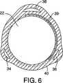
第6図は、更に別の大動脈閉塞カテーテルを示す断面図である。
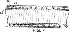
第7図は、ワイヤ強化形血流管孔を形成する方法を示す縦断面図である。
第8図は、加熱後の第7図の構造を示す縦断面図である。
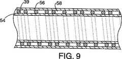
第9図は、第2ワイヤ強化形血流管孔の形成方法を示す縦断面図である。
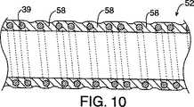
第10図は、加熱後の第9図の構造を示す縦断面図である。
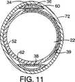
第11図は、大動脈閉塞カテーテルの断面図であり、圧力管孔および膨張管孔を、第4図の大動脈閉塞カテーテルのワイヤ強化形血流管孔に付加する方法を示すものである。
第12図は、大動脈閉塞カテーテルの断面図であり、圧力管孔および膨張管孔を、第5図の大動脈閉塞カテーテルのワイヤ強化形血流管孔に付加する方法を示すものである。
第13図は、大動脈閉塞カテーテルの断面図であり、圧力管孔および膨張管孔を、第6図の大動脈閉塞カテーテルのワイヤ強化形血流管孔に付加する方法を示すものである。
好ましい実施形態の説明
第1図には、患者の心臓を停止させかつ患者を通る酸化血の循環を維持するためのシステムが示されている。このシステムは本発明による大動脈閉塞カテーテル2および他のシステムを例示する目的で示されており、本発明には、その範囲を逸脱することなく、カテーテル、カニューレおよび同類の器具を使用できる。
任意の適当な位置で患者の血管系内に挿入された静脈カニューレ4を介して、血液が患者から吸引される。第1図は、大腿静脈を通って患者の右心房内に通された静脈カニューレ4を示している。また、血液は、肺血管系を通して患者の心臓に通気する通気カテーテル6を介して患者から吸引される。通気カテーテル6を使用するのが好ましいが、心臓の通気は、肺動脈を穿通する針のような他の任意の装置を用いて行なうこともできる。
静脈カニューレ4および通気カテーテル6を介して吸引された血液は、バイパスシステム10(好ましくは、患者を通して酸化血をポンピングするポンプを有している)に導かれる。また、バイパスシステム10には、次の装置すなわち、熱交換器、酸化器、フィルタ、バブルトラップおよび心臓切開リザーバのうちの1つ以上を含めることができる。バイパスシステム10には外部酸化器を含めるのが好ましいが、患者自身の肺を使用して血液を酸化することもできる。
血液がバイパスシステム10に通された後、酸化血は、バイパスシステム10から大動脈閉塞カテーテル2(該大動脈閉塞カテーテルについては、後に詳述する)を介して患者に戻される。大動脈閉塞カテーテル2は閉塞部材12を有し、該閉塞部材12は患者の上行大動脈を閉塞するバルーンが好ましい。上行大動脈を閉塞すると冠状動脈が残余の動脈系から隔絶され、これにより、心臓が酸化血を受け入れることおよび手術が完了する前に早期スタートすることが防止される。閉塞部材12を膨張させるため、膨張流体源14(食塩水が充満された注射器が好ましい)が使用される。
患者の心臓は任意の方法を用いて停止され、好ましい方法は心停止液を使用することである。心停止液は、冠状静脈洞を通して順行的または逆行的に投与することができる。第1図に示すシステムは順行的および逆行的注入の両方を示しているが、必要なのは一方の注入形式のみである。心停止液は任意の種類のものを使用でき、好ましい心停止液は、晶質心停止液と血液との混合物である血液心停止液(blood cardioplegia)である。心停止液源16は、心停止液剤と混合して心停止液を形成するため、バイパスシステム10から血液を吸引する。心停止液は、針18を用いて順行的に導入されかつ冠状静脈洞カテーテル20を用いて逆行的に導入される。冠状静脈洞カテーテル20は、内頸静脈を通って、右心房内および冠状静脈洞20内に通される。好ましくは、冠状静脈洞カテーテル20は、冠状静脈洞を閉塞するためのバルーン(図示せず)を有している。冠状静脈洞カテーテル20は末梢静脈を通して前進させるのが好ましいが、簡単に右心房の開口を通すこともできる。
ここで第1図〜第3図に示すように、大動脈閉塞カテーテル2は、酸化血をバイパスシステム10から患者に戻すための血液戻し管孔22を有している。血液戻し管孔22は、バイパスシステム10からの酸化血を閉塞部材12の両側に注入するための近位側開口24および遠位側開口26を有している。近位側開口24を通して酸化血を供給すると、酸化血は、腋窩動脈、鎖骨下動脈および頸動脈等の上腕頭動脈の下流側の動脈に供給される。カテーテル2の開端部28を含む遠位側開口26を通して酸化血を供給すると、酸化血は、身体の残部に供給される。近位側開口24は好ましくは0.02〜0.2インチ(より好ましくは0.04インチ)の直径を有し、近位側開口24の数は3〜60個の間が好ましい。近位側開口24の全面積は、遠位側開口26の面積の約5〜30%(より好ましくは、約10%)であり、これにより、より多量の酸化血が遠位側開口26を通ることができる。なぜならば、患者の動脈系の大部分は閉塞部材12より遠位側にあるからである。血液戻し管孔22は、バイパスシステム10への連結に適した慣用的な逆目コネクタ30に終端している。血液戻し管孔22は、ベンザルコニウムヘパリンのような慣用的な無トロンボーゲンコーティング(athrombogenic coating)でコーティングし、血液に与えるダメージを最小にするのが好ましい。また、患者内へのカテーテル2の導入を容易にするため、カテーテル2の外面を潤滑性コーティングでコーティングすることができる。任意の適当なコーティングを使用でき、好ましいコーティングとしてポリビニルピロリドンがある。
引き続き第1図〜第3図を参照して説明すると、大動脈閉塞カテーテル2は、上腕頭動脈から患者の大動脈弓に入りかつ穿通により鎖骨下動脈、腋窩動脈または上腕動脈に入るのが好ましい。第1図は、大動脈閉塞カテーテル2が、穿通により腋窩動脈に入りかつ鎖骨下動脈および上腕頭動脈を通るところを示している。大動脈閉塞カテーテル2を穿通により挿入しかつ患者の動脈を通して前進させるとき、非外傷性遠位端を形成すべく、栓塞子32が血液戻し管孔22内に配置される。X線透視を用いて、最初にガイドワイヤ23が動脈に通される。次に、大動脈閉塞カテーテル2およびこれに同伴する栓塞子32が一緒にガイドワイヤ23上に通され、第2図に示すようにカテーテルを位置決めする。ひとたびカテーテル2が位置決めされたならば、栓塞子32およびガイドワイヤ23が除去される。次に、カテーテル2を通って血液が流れ得るようにすることによりカテーテル2から該全ての空気を除去し、またカテーテル2は次にバイパスシステム1に連結される。
第1図および第2図に示すように、大動脈閉塞カテーテル2は、上腕頭動脈を閉塞または部分的に閉塞すべく位置決めされる。これは、通常、危険な状態を招くが、近位側開口24が、鎖骨下動脈、頸動脈および腋窩動脈のような上腕頭動脈より下流側にある動脈に酸化血を供給するので、上腕頭動脈を完全に閉塞しても問題は生じない。かくして、本発明の大動脈閉塞カテーテル2の長所は、閉塞部材12が患者の大動脈弁から離れた位置に容易に位置決めできるため、大動脈弁との接触が問題にならないと同時に、上腕頭動脈の閉塞によって頸動脈への血液供給が遮断されないことである。大動脈閉塞カテーテル2は、閉塞部材12が大動脈弁から離れて位置決めされるため、大動脈弁手術を行なうときに特に有効である。
第1図〜第4図に示すように、大動脈閉塞カテーテル2は、閉塞部材12の近位側および遠位側の圧力をモニタリングするための、圧力モニタ38に連結された第1および第2圧力管孔34、36を有している。第1および第2圧力管孔34、36は、それぞれ、第1および第2圧力ポート35、37を有している。圧力管孔34、36を設けることが好ましいが、圧力検出は、圧力変換器を用いる等の他の任意の方法で行なうことができる。圧力モニタ38は、近位側および遠位側開口24、26を通して血液を供給するときに血圧が過度に高くまたは低くなることを防止するのに使用される。例えば、遠位側開口26が閉塞すなわち遮断されると、全ての血液が強制的に近位側開口24を通されることになるが、これによって上腕頭動脈および頸動脈に好ましくない高い血圧が生じるであろう。患者に血液を供給するときに過度に高い血圧を防止するため、減圧弁(図示せず)を設けることができる。或いは、バイパスシステム10に圧力センサを連結して酸化血の供給を調節することにより、過度の血圧を防止することができる。第1および第2圧力管孔34、36の両方を設けるのが好ましいが、いずれか一方の圧力管孔のみ(例えば第1管孔34のみ)を設けることもできる。圧力管孔34、36は、圧力モニタ38への連結に適したコネクタ33を有している。
第4図には、大動脈閉塞カテーテル2の断面が示されている。圧力管孔34、36は、閉塞部材12を膨張させるのに使用される膨張管孔38に対向する位置に配置されている。大動脈閉塞カテーテル2は、カテーテルシャフト40の周囲に螺旋状に巻回されたワイヤ39で補強するのが好ましい。第5図は圧力管孔34、36および膨張管孔38が互いに隣接して配置されている別の構造を示し、第6図は、圧力管孔34、36および膨張管孔38が大動脈閉塞カテーテル2の周方向に間隔を隔てて配置された構造を示す。カテーテル2の製造方法を以下に詳細に説明する。
再び第1図〜第3図を参照すると、閉塞部材12は、任意の適当な弾性材料または非弾性材料(好ましくはポリウレタン)で作られる膨張バルーンが好ましい。閉塞部材12は、該部材12の近位端42と遠位端44との間の側面41に沿ってシャフト40に接合するのが好ましい。この結果、閉塞部材12は第1図〜第3図に示すように、シャフト40の一方の側方に膨張される。閉塞部材12はその側面41をシャフト40に接合するのが好ましいが、閉塞部材12の近位端42および遠位端44のみをシャフト40に接合して、閉塞部材12がシャフト40の全周方向に拡大できるように構成することもできる。閉塞部材12を膨張させるための膨張開口46を備えた膨張管孔38は、閉塞部材12を膨張させる膨張流体源14に連結するのに適したコネクタ48を有している。
第2図および第4図に示すように、シャフト40はワイヤ39で補強するのが好ましい。シャフト40はワイヤ補強形構造にするのが好ましいが、シャフト40は押出し成形のような他の適当な構造にすることができる。カテーテル2は、非常に可撓性が高く、自由状態で実質的に直線状になるのが好ましい。或いは、カテーテル2の遠位端は、第3図に破線50で示すように僅かに湾曲させることができる。
第7図〜第10図を参照して、ワイヤ補強形シャフト40の製造方法を説明する。この方法は、補強チューブ52を製造することから開始される。第1チューブ54がマンドレル(図示せず)に取り付けられ、ワイヤ39が、第7図および第9図の縦断面図に示す態様で第1チューブ54の周囲に螺旋状に巻回される。ワイヤ39は、0.001〜0.015インチ(好ましくは0.007インチ)の直径をもつステンレス鋼が好ましい。次に、ワイヤ39上に第2チューブ56が配置され、第1および第2チューブ54、56が熱収縮性チューブ(図示せず)内に封入されて、第1および第2チューブ54、56およびワイヤ39が、それぞれ第8図および第10図に示す補強チューブ52を形成する。第1および第2チューブ54、56は、0.001〜0.010インチの厚さを有するのが好ましく、より好ましくは0.003インチの厚さを有する。第1および第2チューブ54、56は任意の適当な材料で作ることができ、好ましい材料はポリウレタンである。
ワイヤ39は、シャフト40のより大きな間隔を隔てた周回部分58(該部分58に、近位側開口24および遠位側開口26がワイヤ39を切断することなく形成される)が形成されるようにして第2チューブ56の回りに巻回されるのが好ましい。第7図および第8図は、近位側開口24および遠位側開口26が形成される部分58で、ワイヤ39の隣接部分間に約0.040インチの均一な間隔が形成されているところが示されている。第9図および第10図は、小さい間隔と大きい間隔とが交互に形成されているところを示し、近位側開口24および遠位側開口26は大きい間隔を有する部分58に形成される。更に別の方法は、ワイヤ39を切断することなく近位側開口24および遠位側開口26を形成できる充分に大きい均一間隔をシャフト40の全長に亘って形成する方法である。第8図および第10図には、ワイヤ39の隣接部分間の僅かな凹みが示されているが、これらの凹みは、後述のようにして圧力管孔34、36および膨張管孔38が付加されるときに、最終的に充填される。
第8図および第10図に示す補強チューブ52が形成された後、第1および第2圧力管孔34、36および膨張管孔38が補強チューブ52に接合される。第11図〜第13図には、第4図〜第6図に示す断面構造を形成する方法がそれぞれ示されている。第11図は、D形押出し成形体60により一体に形成された圧力管孔34、36を示し、D形押出し成形体60は、膨張管孔38用の他のD形押出し成形体62に対向して配置されている。第12図は、圧力管孔34、36および膨張管孔38の両者が単一のD形押出し成形体64により形成されているものを示している。第13図には、圧力管孔34、36および膨張管孔38の各々が別々のD形押出し成形体66、68、70により形成され、かつ管孔34、36、38が互いに間隔を隔てて配置されているところが示されている。
圧力管孔34、36および膨張管孔38上には、外側チューブ72が配置される。好ましくは、外側チューブ72を膨張させておき、次に、補強チューブ52、圧力管孔34、36および膨張管孔38を外側チューブ72内に配置する。次に外側チューブ72を収縮させ、第11図〜第13図に示すように、外側チューブ72を圧力管孔34、36、膨張管孔38および補強チューブ52の回りに緊縮させる。外側チューブ72は第1および第2チューブ54、56と同じ材料で作るのが好ましく、0.001〜0.010インチ(より好ましくは0.003インチ)の厚さを有する。外側チューブ72上には熱収縮性チューブ(図示せず)が配置され、全構造体が加熱されて第4図〜第6図の一体構造が形成される。次に、圧力管孔34、36の圧力ポート35、37、膨張管孔38の開口46、および血液戻し管孔22の近位側開口24および遠位側開口26が形成される。血液戻し管孔22の外側に圧力管孔34、36および膨張管孔38を付加することの長所は、圧力ポート35、37および膨張管孔38の開口46がワイヤ39を切断しないことにある。
大動脈閉塞カテーテル2は好ましくはポリウレタンで作られた柔軟先端部74を有し、該柔軟先端部74は、この位置をX線透視を用いて視認できるようにするため、X線不透過性材料をドーピングしておくのが好ましい。柔軟先端部74は補強チューブ52の成形後にシャフト40の端部に接合され、従って先端部74がワイヤ39で補強されることはない。カテーテル2および閉塞部材12の視認性および位置決め能力を一層向上させるため、閉塞部材12の両側にX線不透過性マーカ76が設けられる。柔軟先端部74を貫通する遠位側開口26も形成されている。
以上は本発明の好ましい説明であるが、本発明の範囲から逸脱することなく種々の変更を行なうことができる。例えば、閉塞部材12はバルーン以外の膨張可能部材にすることができ、大動脈閉塞カテーテル2は、遠位端を上腕頭動脈内に入れて左鎖骨下動脈等の他の動脈に通すことにより逆方向に使用でき、かつ大動脈閉塞カテーテル2には、患者の上行大動脈に心停止液を供給しかつ大動脈根に通気するための管孔を設けることもできる。かくして、上記説明は、請求の範囲で定められる本発明の範囲を制限するものではない。The present invention relates to a method and apparatus for occluding a patient's ascending aorta and returning oxidative blood to the patient when the patient is maintained by a bypass system. The present invention is particularly effective when performing surgery on the heart and large vessels.
In conventional open heart surgery, the patient's heart is accessed through a large incision in the patient's chest, such as a median sternotomy. Once the patient's heart is exposed, various catheters, cannulas and clamps are applied directly to the patient's heart and large vessels. Blood is aspirated from the patient via a venous cannula and returned to the patient via an arterial return cannula, which is typically inserted via an ascending aortic purse string suture. The heart is stopped by injecting cardioplegia into the ascending aorta using a needle. The ascending aorta is generally occluded by an external cross clamp applied around the ascending aorta to isolate the coronary artery from the remaining arterial system.
Recent advances in cardiac surgery have provided cannulas and catheters that can occlude the patient's ascending aorta, return oxidative blood to the patient, and provide cardiac arrest fluid to the patient without the need for direct access to the patient's heart. Such systems are disclosed in US Pat. Nos. 5,584,803, 5,478,309, and Reissue Patent 35,352. The devices and methods disclosed in these patents allow surgeons to perform various operations on the patient's heart and large blood vessels, such as bypass grafting and valve replacement, without having to make a large incision in the patient's chest. . Such surgery can reduce the pain and damage experienced by the patient compared to traditional open heart surgery.
Other advantages disclosed in the above-mentioned U.S. Pat.Nos. 5,584,803, 5,478,309, and Reissue Patent 35,352 are based on the placement of a balloon in the aorta rather than applying an external clamp around the aorta. It can be blocked. By occluding the ascending aorta using a balloon, the amount of thrombus released into the bloodstream is reduced compared to an external cross clamp.
Although the above system can perform a wide range of operations on a stopped heart, the placement of the aortic occlusion balloon must be positioned within a relatively small space between the aortic valve and the brachiocephalic artery. Because it has to be, it is often challenging. If the brachiocephalic artery is unexpectedly occluded, oxidized blood will not be supplied to the right carotid artery (the carotid artery is branched from the brachiocephalic artery and supplies blood to the patient's brain). It is a danger. Balloon placement is particularly challenging when performing aortic valve surgery. This is because the balloon must be positioned far enough away from the aortic valve to allow the surgeon to perform aortic valve surgery without being blocked by the balloon.
Accordingly, an object of the present invention is to provide an aortic occlusion catheter having an occlusion member that can be easily placed in a brachiocephalic artery of a patient.
SUMMARY OF THE INVENTION The present invention provides a method and aortic occlusion catheter that occludes a patient's brachiocephalic artery and delivers oxidative blood to the patient from a bypass system. The aortic occlusion catheter is inserted by penetration into the patient's arterial system and passed through the junction between the brachiocephalic artery and the ascending aorta. In a preferred embodiment, the aortic occlusion catheter preferably enters the patient's arterial system via penetration into the patient's axillary or subclavian artery.
The aortic occlusion catheter has an occlusion member disposed within the ascending aorta and enlarged to occlude the patient's ascending aorta to isolate the coronary artery from the patient's remaining arteries. The occlusion member (preferably a balloon) is preferably attached to the catheter shaft along the portion between the proximal and distal ends of the occlusion member. When the closure member is expanded, the closure member is expanded to one side of the shaft. In a preferred embodiment, the enlarged side of the occlusion member is positioned to expand toward the aortic valve.
The aortic occlusion catheter also has a blood flow lumen with first and second openings for returning oxidised blood to the patient. The first and second openings are disposed on both sides of the occlusion member, whereby oxidative blood is supplied to both sides of the occlusion member. One of the openings supplies oxygenated blood to the artery upstream from the junction of the brachiocephalic artery and the aortic arch, while the other opening supplies oxygenated blood to the rest of the body. The advantage of providing openings on both sides of the occlusion member is that the occlusion of the brachiocephalic artery does not pose a risk to the patient because oxidative blood is supplied to both sides of the occlusion member. Another advantage of an aortic occlusion catheter is that the occlusion member can be easily positioned away from the aortic valve, thereby maximizing the working space for performing aortic valve surgery.
Also, the aortic occlusion catheter preferably has two pressure tubes for measuring pressure on both sides of the occlusion member. Although it is preferred to provide two pressure holes, only one pressure hole is essential. The pressure tube is connected to a pressure monitor that measures blood pressure on both sides of the occlusion member. Pressure monitors are used to prevent excessively high or low blood pressure (particularly excessively high blood pressure in the carotid artery).
These and other features will become apparent from the following description of the preferred embodiment.
[Brief description of the drawings]
FIG. 1 is a partial cross-sectional view of a patient's heart and vasculature showing an aortic occlusion catheter of the present invention in combination with a bypass system.
FIG. 2 is an enlarged view showing the aortic occlusion catheter of FIG.
FIG. 3 is a side view showing the aortic occlusion catheter of FIGS. 1 and 2. FIG.
FIG. 4 is a sectional view taken along line AA of FIG.
FIG. 5 is a sectional view showing another aortic occlusion catheter.
FIG. 6 is a sectional view showing still another aortic occlusion catheter.
FIG. 7 is a longitudinal sectional view showing a method of forming a wire-reinforced blood flow tube hole.
FIG. 8 is a longitudinal sectional view showing the structure of FIG. 7 after heating.
FIG. 9 is a longitudinal sectional view showing a method for forming a second wire-reinforced blood flow tube hole.
FIG. 10 is a longitudinal sectional view showing the structure of FIG. 9 after heating.
FIG. 11 is a cross-sectional view of an aortic occlusion catheter and shows a method of adding a pressure tube and an expansion tube to the wire-enhanced blood flow tube of the aortic occlusion catheter of FIG.
FIG. 12 is a cross-sectional view of an aortic occlusion catheter and shows a method of adding a pressure tube and an expansion tube to the wire-enhanced blood flow tube of the aortic occlusion catheter of FIG.
FIG. 13 is a cross-sectional view of an aortic occlusion catheter and shows a method of adding a pressure tube and an expansion tube to the wire-enhanced blood flow tube of the aortic occlusion catheter of FIG.
DESCRIPTION OF PREFERRED EMBODIMENTS FIG. 1 shows a system for stopping a patient's heart and maintaining the circulation of oxidised blood through the patient. This system is shown for purposes of illustrating the
Blood is aspirated from the patient via a venous cannula 4 inserted into the patient's vasculature at any suitable location. FIG. 1 shows a venous cannula 4 passed through the femoral vein and into the patient's right atrium. In addition, blood is aspirated from the patient via a ventilation catheter 6 that vents the patient's heart through the pulmonary vasculature. Although the use of a ventilation catheter 6 is preferred, cardiac ventilation can be performed using any other device such as a needle that penetrates the pulmonary artery.
Blood aspirated through the venous cannula 4 and ventilation catheter 6 is directed to a bypass system 10 (preferably having a pump for pumping oxidised blood through the patient). The
After the blood is passed through the
The patient's heart is stopped using any method, and the preferred method is to use a cardioplegia solution. Cardiac arrest fluid can be administered antegradely or retrogradely through the coronary sinus. Although the system shown in FIG. 1 shows both antegrade and retrograde injection, only one type of injection is required. Any type of cardioplegia can be used, and the preferred cardioplegia is blood cardioplegia, which is a mixture of crystalline cardioplegia and blood. The
Here, as shown in FIGS. 1 to 3, the
With continued reference to FIGS. 1-3, the
As shown in FIGS. 1 and 2, the
As shown in FIGS. 1-4, the
FIG. 4 shows a cross section of the
Referring again to FIGS. 1-3, the
As shown in FIGS. 2 and 4, the
A method for manufacturing the wire-reinforced
The
After the reinforcing
An
The
While the above is a preferred description of the invention, various changes can be made without departing from the scope of the invention. For example, the
Claims (1)
Translated fromJapanese血流管孔を備えたシャフトを有し、血流管孔は患者のための全バイパス維持が行えるサイズを有し、
シャフトに取り付けられた閉塞部材を有し、該閉塞部材は収縮形状および拡大形状を有し、拡大形状は、患者の上行大動脈を閉塞できるサイズおよび形状になり、
シャフトはまた、血流管孔と流体連通する第1および第2開口を備え、第1開口は閉塞部材の近位側に配置されかつ第2開口は閉塞部材の遠位側に配置されていることを特徴とするカテーテルシステム。In a catheter system that occludes the patient's ascending aorta and returns oxidative blood from the bypass system to the patient,
Having a shaft with a blood flow lumen, the blood flow lumen having a size capable of maintaining a full bypass for the patient;
An occlusion member attached to the shaft, the occlusion member having a contracted shape and an enlarged shape, the enlarged shape being sized and shaped to occlude a patient's ascending aorta,
The shaft also includes first and second openings in fluid communication with the blood flow lumen, the first opening being disposed proximal of the occlusion member and the second opening being disposed distal to the occlusion member. A catheter system characterized by the above.
Applications Claiming Priority (3)
| Application Number | Priority Date | Filing Date | Title |
|---|---|---|---|
| US08/831,102US5755687A (en) | 1997-04-01 | 1997-04-01 | Methods and devices for occluding a patient's ascending aorta |
| US08/831,102 | 1997-04-01 | ||
| PCT/US1998/006403WO1998043696A1 (en) | 1997-04-01 | 1998-03-31 | Methods and devices for occluding a patient's ascending aorta |
Publications (3)
| Publication Number | Publication Date |
|---|---|
| JP2000511461A JP2000511461A (en) | 2000-09-05 |
| JP2000511461A5 JP2000511461A5 (en) | 2005-11-24 |
| JP4334022B2true JP4334022B2 (en) | 2009-09-16 |
Family
ID=25258281
Family Applications (1)
| Application Number | Title | Priority Date | Filing Date |
|---|---|---|---|
| JP54195598AExpired - LifetimeJP4334022B2 (en) | 1997-04-01 | 1998-03-31 | Method and apparatus for occluding a patient's ascending aorta |
Country Status (9)
| Country | Link |
|---|---|
| US (3) | US5755687A (en) |
| EP (1) | EP0912212B1 (en) |
| JP (1) | JP4334022B2 (en) |
| AT (1) | ATE286761T1 (en) |
| AU (1) | AU742276B2 (en) |
| CA (1) | CA2256570A1 (en) |
| DE (1) | DE69828561T2 (en) |
| ES (1) | ES2236897T3 (en) |
| WO (1) | WO1998043696A1 (en) |
Families Citing this family (121)
| Publication number | Priority date | Publication date | Assignee | Title |
|---|---|---|---|---|
| US7678098B2 (en)* | 1996-04-10 | 2010-03-16 | Endoscopic Technologies, Inc. | Venous cannula and cardiopulmonary bypass system |
| US5873366A (en)* | 1996-11-07 | 1999-02-23 | Chim; Nicholas | Method for transmyocardial revascularization |
| US6035856A (en) | 1997-03-06 | 2000-03-14 | Scimed Life Systems | Percutaneous bypass with branching vessel |
| US6155264A (en) | 1997-03-06 | 2000-12-05 | Scimed Life Systems, Inc. | Percutaneous bypass by tunneling through vessel wall |
| US6026814A (en) | 1997-03-06 | 2000-02-22 | Scimed Life Systems, Inc. | System and method for percutaneous coronary artery bypass |
| US5755687A (en)* | 1997-04-01 | 1998-05-26 | Heartport, Inc. | Methods and devices for occluding a patient's ascending aorta |
| US6090096A (en) | 1997-04-23 | 2000-07-18 | Heartport, Inc. | Antegrade cardioplegia catheter and method |
| US6217546B1 (en) | 1997-05-19 | 2001-04-17 | United States Surgical Corporation | Catheter system |
| JP3018161B2 (en)* | 1997-06-09 | 2000-03-13 | 広島大学長 | Blood circulation assist device |
| US6443158B1 (en) | 1997-06-19 | 2002-09-03 | Scimed Life Systems, Inc. | Percutaneous coronary artery bypass through a venous vessel |
| US6092526A (en) | 1997-06-19 | 2000-07-25 | Scimed Life Systems, Inc. | Percutaneous chamber-to-artery bypass |
| US6213126B1 (en) | 1997-06-19 | 2001-04-10 | Scimed Life Systems, Inc. | Percutaneous artery to artery bypass using heart tissue as a portion of a bypass conduit |
| US6123725A (en)* | 1997-07-11 | 2000-09-26 | A-Med Systems, Inc. | Single port cardiac support apparatus |
| US6099506A (en) | 1997-09-26 | 2000-08-08 | Macoviak; John A. | Introducer and perfusion cannula |
| AU1712599A (en)* | 1997-12-08 | 1999-06-28 | Cardeon Corporation | Aortic catheter and methods for inducing cardioplegic arrest and for selective aortic perfusion |
| US6159178A (en) | 1998-01-23 | 2000-12-12 | Heartport, Inc. | Methods and devices for occluding the ascending aorta and maintaining circulation of oxygenated blood in the patient when the patient's heart is arrested |
| US6295990B1 (en)* | 1998-02-03 | 2001-10-02 | Salient Interventional Systems, Inc. | Methods and systems for treating ischemia |
| US6179827B1 (en) | 1998-03-16 | 2001-01-30 | Chase Medical | Catheter having integral expandable/collapsible lumen |
| US6190357B1 (en) | 1998-04-21 | 2001-02-20 | Cardiothoracic Systems, Inc. | Expandable cannula for performing cardiopulmonary bypass and method for using same |
| US6508777B1 (en) | 1998-05-08 | 2003-01-21 | Cardeon Corporation | Circulatory support system and method of use for isolated segmental perfusion |
| US6325813B1 (en) | 1998-08-18 | 2001-12-04 | Scimed Life Systems, Inc. | Method and apparatus for stabilizing vascular wall |
| US6726651B1 (en) | 1999-08-04 | 2004-04-27 | Cardeon Corporation | Method and apparatus for differentially perfusing a patient during cardiopulmonary bypass |
| US6641558B1 (en)* | 1998-09-30 | 2003-11-04 | A-Med Systems, Inc. | Method and apparatus for preventing air embolisms |
| US6056720A (en)* | 1998-11-24 | 2000-05-02 | Embol-X, Inc. | Occlusion cannula and methods of use |
| US6228018B1 (en) | 1999-02-05 | 2001-05-08 | My-Tech, Inc. | Removable left ventricular assist device with an aortic support apparatus |
| US6837864B1 (en)* | 1999-02-19 | 2005-01-04 | Endoscopic Technologies, Inc. | Multichannel catheter with obturator |
| AU3859300A (en)* | 1999-02-19 | 2000-09-04 | Endoscopic Technologies, Inc. | Multichannel catheter with obturator |
| US6210363B1 (en)* | 1999-02-23 | 2001-04-03 | Cardeon Corporation | Methods and devices for occluding a vessel and performing differential perfusion |
| AU3749400A (en)* | 1999-03-16 | 2000-10-04 | Chase Medical Inc. | Catheter having varying resiliency balloon |
| US6319244B2 (en) | 1999-03-16 | 2001-11-20 | Chase Medical, L.P. | Catheter with flexible and rigid reinforcements |
| US6287319B1 (en) | 1999-03-30 | 2001-09-11 | Amed Systems, Inc. | Cannula with balloon tip |
| US6295877B1 (en) | 1999-03-30 | 2001-10-02 | A-Med Systems, Inc. | Pressure sensing cannula |
| US6383172B1 (en)* | 1999-04-02 | 2002-05-07 | Coaxia, Inc. | Retrograde venous perfusion with isolation of cerebral circulation |
| WO2000067641A1 (en)* | 1999-05-11 | 2000-11-16 | Williamson Warren P Iv | Surgical clamp devices and methods especially useful in cardiac surgery |
| US6436071B1 (en)* | 1999-06-08 | 2002-08-20 | The Trustees Of Columbia University In The City Of New York | Intravascular systems for corporeal cooling |
| EP1060758A1 (en)* | 1999-06-15 | 2000-12-20 | Medtronic, Inc. | Aortic occlusion cannula |
| US7022100B1 (en) | 1999-09-03 | 2006-04-04 | A-Med Systems, Inc. | Guidable intravascular blood pump and related methods |
| AU784413B2 (en)* | 1999-11-11 | 2006-03-30 | Edwards Lifesciences Corporation | Venous return cannula with enhanced drainage |
| US6409758B2 (en)* | 2000-07-27 | 2002-06-25 | Edwards Lifesciences Corporation | Heart valve holder for constricting the valve commissures and methods of use |
| WO2002056955A1 (en)* | 2001-01-18 | 2002-07-25 | Edwards Lifesciences Corporation | Arterial cannula with perforated filter lumen |
| US6994666B2 (en)* | 2001-06-05 | 2006-02-07 | Edwards Lifesciences Corporation | Non-porous smooth ventricular assist device conduit |
| US20030045859A1 (en)* | 2001-06-11 | 2003-03-06 | Larry Dominguez | Delivery system using balloon catheter |
| US6942672B2 (en) | 2001-10-23 | 2005-09-13 | Vascor, Inc. | Method and apparatus for attaching a conduit to the heart or a blood vessel |
| DE60229416D1 (en)* | 2001-10-25 | 2008-11-27 | Univ Emory | Catheter for modified perfusion |
| US20050004515A1 (en)* | 2002-11-15 | 2005-01-06 | Hart Charles C. | Steerable kink resistant sheath |
| DE50209306D1 (en) | 2002-12-31 | 2007-03-08 | Abbott Lab Vascular Entpr Ltd | Catheter with a more flexible area between stem and tip, and method of making the same |
| US8721515B2 (en)* | 2003-01-31 | 2014-05-13 | L-Vad Technology, Inc. | Rigid body aortic blood pump implant |
| US8540618B2 (en) | 2003-01-31 | 2013-09-24 | L-Vad Technology, Inc. | Stable aortic blood pump implant |
| US7473237B2 (en)* | 2003-02-25 | 2009-01-06 | The Cleveland Clinic Foundation | Apparatus for auto-retroperfusion of a coronary vein |
| US7250041B2 (en)* | 2003-03-12 | 2007-07-31 | Abbott Cardiovascular Systems Inc. | Retrograde pressure regulated infusion |
| US20050015048A1 (en) | 2003-03-12 | 2005-01-20 | Chiu Jessica G. | Infusion treatment agents, catheters, filter devices, and occlusion devices, and use thereof |
| CA2523270A1 (en)* | 2003-04-25 | 2004-11-11 | Applied Medical Resources Corporation | Steerable kink-resistant sheath |
| US7628769B2 (en)* | 2004-05-27 | 2009-12-08 | Abbott Laboratories | Catheter having overlapping stiffening members |
| US20070078439A1 (en)* | 2004-05-27 | 2007-04-05 | Axel Grandt | Multiple lumen catheter and method of making same |
| US7794448B2 (en)* | 2004-05-27 | 2010-09-14 | Abbott Laboratories | Multiple lumen catheter and method of making same |
| US7785318B2 (en)* | 2004-05-27 | 2010-08-31 | Abbott Laboratories | Catheter having plurality of stiffening members |
| US7815627B2 (en)* | 2004-05-27 | 2010-10-19 | Abbott Laboratories | Catheter having plurality of stiffening members |
| US7785439B2 (en)* | 2004-09-29 | 2010-08-31 | Abbott Laboratories Vascular Enterprises Limited | Method for connecting a catheter balloon with a catheter shaft of a balloon catheter |
| US7658723B2 (en)* | 2004-05-27 | 2010-02-09 | Abbott Laboratories | Catheter having plurality of stiffening members |
| US7625353B2 (en)* | 2004-05-27 | 2009-12-01 | Abbott Laboratories | Catheter having first and second guidewire tubes and overlapping stiffening members |
| CA2592142A1 (en)* | 2004-12-22 | 2006-06-29 | Emory University | Therapeutic adjuncts to enhance the organ protective effects of postconditioning |
| US7775966B2 (en) | 2005-02-24 | 2010-08-17 | Ethicon Endo-Surgery, Inc. | Non-invasive pressure measurement in a fluid adjustable restrictive device |
| US7789846B2 (en)* | 2005-01-25 | 2010-09-07 | Thermopeutix, Inc. | System and methods for selective thermal treatment |
| US7699770B2 (en) | 2005-02-24 | 2010-04-20 | Ethicon Endo-Surgery, Inc. | Device for non-invasive measurement of fluid pressure in an adjustable restriction device |
| US7927270B2 (en) | 2005-02-24 | 2011-04-19 | Ethicon Endo-Surgery, Inc. | External mechanical pressure sensor for gastric band pressure measurements |
| US8016744B2 (en) | 2005-02-24 | 2011-09-13 | Ethicon Endo-Surgery, Inc. | External pressure-based gastric band adjustment system and method |
| US8066629B2 (en) | 2005-02-24 | 2011-11-29 | Ethicon Endo-Surgery, Inc. | Apparatus for adjustment and sensing of gastric band pressure |
| US7658196B2 (en) | 2005-02-24 | 2010-02-09 | Ethicon Endo-Surgery, Inc. | System and method for determining implanted device orientation |
| US7775215B2 (en) | 2005-02-24 | 2010-08-17 | Ethicon Endo-Surgery, Inc. | System and method for determining implanted device positioning and obtaining pressure data |
| US7320665B2 (en) | 2005-03-02 | 2008-01-22 | Venkataramana Vijay | Cardiac Ventricular Geometry Restoration Device and Treatment for Heart Failure |
| US20060199995A1 (en)* | 2005-03-02 | 2006-09-07 | Venkataramana Vijay | Percutaneous cardiac ventricular geometry restoration device and treatment for heart failure |
| WO2006127931A2 (en)* | 2005-05-23 | 2006-11-30 | Abbott Laboratories | Multiple lumen catheter and method of making same |
| US8152710B2 (en) | 2006-04-06 | 2012-04-10 | Ethicon Endo-Surgery, Inc. | Physiological parameter analysis for an implantable restriction device and a data logger |
| US8870742B2 (en) | 2006-04-06 | 2014-10-28 | Ethicon Endo-Surgery, Inc. | GUI for an implantable restriction device and a data logger |
| US8273054B2 (en) | 2006-09-01 | 2012-09-25 | St. Jude Medical Puerto Rico, Llc | System and method for arterial access |
| ATE516004T1 (en)* | 2006-12-13 | 2011-07-15 | Koninkl Philips Electronics Nv | FEEDING TUBE |
| US8187163B2 (en) | 2007-12-10 | 2012-05-29 | Ethicon Endo-Surgery, Inc. | Methods for implanting a gastric restriction device |
| US8100870B2 (en) | 2007-12-14 | 2012-01-24 | Ethicon Endo-Surgery, Inc. | Adjustable height gastric restriction devices and methods |
| US8377079B2 (en) | 2007-12-27 | 2013-02-19 | Ethicon Endo-Surgery, Inc. | Constant force mechanisms for regulating restriction devices |
| US8142452B2 (en) | 2007-12-27 | 2012-03-27 | Ethicon Endo-Surgery, Inc. | Controlling pressure in adjustable restriction devices |
| US8192350B2 (en) | 2008-01-28 | 2012-06-05 | Ethicon Endo-Surgery, Inc. | Methods and devices for measuring impedance in a gastric restriction system |
| US8337389B2 (en) | 2008-01-28 | 2012-12-25 | Ethicon Endo-Surgery, Inc. | Methods and devices for diagnosing performance of a gastric restriction system |
| US8591395B2 (en) | 2008-01-28 | 2013-11-26 | Ethicon Endo-Surgery, Inc. | Gastric restriction device data handling devices and methods |
| US8221439B2 (en) | 2008-02-07 | 2012-07-17 | Ethicon Endo-Surgery, Inc. | Powering implantable restriction systems using kinetic motion |
| US7844342B2 (en) | 2008-02-07 | 2010-11-30 | Ethicon Endo-Surgery, Inc. | Powering implantable restriction systems using light |
| US8114345B2 (en) | 2008-02-08 | 2012-02-14 | Ethicon Endo-Surgery, Inc. | System and method of sterilizing an implantable medical device |
| US8057492B2 (en) | 2008-02-12 | 2011-11-15 | Ethicon Endo-Surgery, Inc. | Automatically adjusting band system with MEMS pump |
| US8591532B2 (en) | 2008-02-12 | 2013-11-26 | Ethicon Endo-Sugery, Inc. | Automatically adjusting band system |
| US8034065B2 (en) | 2008-02-26 | 2011-10-11 | Ethicon Endo-Surgery, Inc. | Controlling pressure in adjustable restriction devices |
| US8187162B2 (en) | 2008-03-06 | 2012-05-29 | Ethicon Endo-Surgery, Inc. | Reorientation port |
| US8233995B2 (en) | 2008-03-06 | 2012-07-31 | Ethicon Endo-Surgery, Inc. | System and method of aligning an implantable antenna |
| JP5013380B2 (en)* | 2009-10-29 | 2012-08-29 | 朝日インテック株式会社 | Medical tube and catheter using the same |
| EP2560722A2 (en) | 2010-04-21 | 2013-02-27 | The Regents of the University of Michigan | Fluoroscopy-independent, endovascular aortic occlusion system |
| US8267887B2 (en)* | 2010-05-26 | 2012-09-18 | Miracor Medical Systems Gmbh | Treating heart tissue |
| JP2012196498A (en)* | 2012-06-14 | 2012-10-18 | Asahi Intecc Co Ltd | Medical tube |
| JP5660737B2 (en)* | 2012-07-20 | 2015-01-28 | 日本ライフライン株式会社 | Electrode catheter and method for producing the same |
| AU2013344788B2 (en) | 2012-11-15 | 2016-02-25 | Cardiac Pacemakers, Inc. | Guide catheter occlusion balloon with active inflation |
| US9474882B2 (en) | 2013-02-26 | 2016-10-25 | Prytime Medical Devices, Inc. | Fluoroscopy-independent balloon guided occlusion catheter and methods |
| US10575743B2 (en) | 2013-04-11 | 2020-03-03 | Biosense Webster (Israel) Ltd. | High electrode density basket catheter |
| US10602947B2 (en)* | 2013-04-11 | 2020-03-31 | Biosense Webster (Israel), Ltd. | High density electrode structure |
| US10569062B2 (en) | 2013-09-09 | 2020-02-25 | Prytime Medical Devices, Inc. | Low profile occlusion catheter |
| US10029070B2 (en)* | 2014-02-03 | 2018-07-24 | Boston Scientific Scimed, Inc. | Crescent channel dye flow enabled guide catheters |
| US9968740B2 (en) | 2014-03-25 | 2018-05-15 | Surefire Medical, Inc. | Closed tip dynamic microvalve protection device |
| US10232142B2 (en) | 2014-06-10 | 2019-03-19 | Prytime Medical Devices, Inc. | Conduit guiding tip |
| CA2980018C (en) | 2015-03-19 | 2018-02-20 | Prytime Medical Devices, Inc. | System and method for low-profile occlusion balloon catheter |
| US20160287839A1 (en) | 2015-03-31 | 2016-10-06 | Surefire Medical, Inc. | Apparatus and Method for Infusing an Immunotherapy Agent to a Solid Tumor for Treatment |
| US10849521B2 (en)* | 2015-12-23 | 2020-12-01 | Biosense Webster (Israel) Ltd. | Multi-layered catheter shaft construction with embedded single axial sensors, and related methods |
| US10368872B2 (en) | 2016-06-02 | 2019-08-06 | Prytime Medical Devices, Inc. | System and method for low profile occlusion balloon catheter |
| US11400263B1 (en) | 2016-09-19 | 2022-08-02 | Trisalus Life Sciences, Inc. | System and method for selective pressure-controlled therapeutic delivery |
| EP4327732A3 (en) | 2017-01-12 | 2024-04-24 | The Regents of The University of California | Endovascular perfusion augmentation for critical care |
| CA3060519A1 (en) | 2017-04-21 | 2018-10-25 | The Regents Of The University Of California | Aortic flow meter and pump for partial-aortic occlusion |
| US11020075B2 (en) | 2017-05-12 | 2021-06-01 | Cardiac Pacemakers, Inc. | Implantation of an active medical device using the internal thoracic vasculature |
| KR20200022464A (en)* | 2017-07-26 | 2020-03-03 | 아사히 인텍크 가부시키가이샤 | Balloon Catheter |
| US20190298983A1 (en)* | 2018-01-15 | 2019-10-03 | Surefire Medical, Inc. | Injection Port for Therapeutic Delivery |
| US11850398B2 (en) | 2018-08-01 | 2023-12-26 | Trisalus Life Sciences, Inc. | Systems and methods for pressure-facilitated therapeutic agent delivery |
| EP3833273A4 (en) | 2018-08-06 | 2022-06-29 | Prytime Medical Devices, Inc. | System and method for low profile occlusion balloon catheter |
| US11338117B2 (en) | 2018-10-08 | 2022-05-24 | Trisalus Life Sciences, Inc. | Implantable dual pathway therapeutic agent delivery port |
| US12433597B2 (en) | 2019-06-04 | 2025-10-07 | Trisalus Life Sciences, Inc. | Atraumatic occlusive system with compartment for measurement of vascular pressure change |
| EP4121159A2 (en) | 2020-03-16 | 2023-01-25 | Certus Critical Care, Inc. | Blood flow control devices, systems, and methods and error detection thereof |
| WO2022197895A1 (en) | 2021-03-18 | 2022-09-22 | Prytime Medical Devices, Inc. | Vascular occlusion catheter |
| JP7403617B1 (en) | 2022-12-09 | 2023-12-22 | 日本ライフライン株式会社 | catheter |
Family Cites Families (268)
| Publication number | Priority date | Publication date | Assignee | Title |
|---|---|---|---|---|
| US231601A (en)* | 1880-08-24 | Montgomeby | ||
| US303757A (en)* | 1884-08-19 | Tkoit | ||
| US299622A (en)* | 1884-06-03 | Refrigerating apparatus | ||
| US554803A (en) | 1896-02-18 | Belt-fastener | ||
| US150960A (en)* | 1874-05-19 | Improvement in machinery for polishing buttons | ||
| US280225A (en)* | 1883-06-26 | Missotjei | ||
| US33258A (en)* | 1861-09-10 | Improvement in gas-burners | ||
| US1282881A (en)* | 1917-07-07 | 1918-10-29 | John T Landis | Pneumatic dilator. |
| US2029236A (en)* | 1934-04-24 | 1936-01-28 | Klophaus Werner | Combination pen and calendar |
| US2308484A (en)* | 1939-01-16 | 1943-01-19 | Davol Rubber Co | Catheter |
| US2531730A (en)* | 1948-09-01 | 1950-11-28 | Gomco Surgical Mfg Corp | Surgical aspirator |
| US2854982A (en)* | 1958-01-22 | 1958-10-07 | Vito V Pagano | Nasopharyngeal tube |
| BE631635A (en)* | 1962-04-28 | |||
| US3435826A (en) | 1964-05-27 | 1969-04-01 | Edwards Lab Inc | Embolectomy catheter |
| US3385300A (en)* | 1965-08-10 | 1968-05-28 | Holter Company | Cervical cannula |
| GB1127325A (en)* | 1965-08-23 | 1968-09-18 | Henry Berry | Improved instrument for inserting artificial heart valves |
| US3587115A (en)* | 1966-05-04 | 1971-06-28 | Donald P Shiley | Prosthetic sutureless heart valves and implant tools therefor |
| US3671979A (en)* | 1969-09-23 | 1972-06-27 | Univ Utah | Catheter mounted artificial heart valve for implanting in close proximity to a defective natural heart valve |
| SE336642B (en)* | 1969-10-28 | 1971-07-12 | Astra Meditec Ab | |
| US3635223A (en)* | 1969-12-02 | 1972-01-18 | Us Catheter & Instr Corp | Embolectomy catheter |
| US3692018A (en)* | 1970-02-11 | 1972-09-19 | Robert H Goetz | Cardiac assistance device |
| US3634924A (en) | 1970-04-20 | 1972-01-18 | American Hospital Supply Corp | Method of making multilumen balloon catheter |
| GB1340788A (en)* | 1971-02-04 | 1974-01-30 | Matburn Holdings Ltd | Nasal tampons |
| US3755823A (en)* | 1971-04-23 | 1973-09-04 | Hancock Laboratories Inc | Flexible stent for heart valve |
| US3788328A (en)* | 1971-04-29 | 1974-01-29 | Sherwood Medical Ind Inc | Cardiovascular catheter |
| GB1402255A (en) | 1971-09-24 | 1975-08-06 | Smiths Industries Ltd | Medical or surgical devices of the kind having an inflatable balloon |
| US3769960A (en)* | 1972-04-17 | 1973-11-06 | Us Health Education & Welfare | Intra-aortic balloon system |
| US3837347A (en)* | 1972-04-20 | 1974-09-24 | Electro Catheter Corp | Inflatable balloon-type pacing probe |
| AU5722173A (en)* | 1972-07-04 | 1975-01-09 | Stanley Francis Duturbure | Catheter tube |
| US3833003A (en)* | 1972-07-05 | 1974-09-03 | A Taricco | Intravascular occluding catheter |
| US3903895A (en)* | 1973-01-05 | 1975-09-09 | Sherwood Medical Ind Inc | Cardiovascular catheter |
| US3812860A (en) | 1973-04-05 | 1974-05-28 | Int Paper Co | Retention catheter |
| US3734100A (en) | 1973-05-07 | 1973-05-22 | Medical Products Corp | Catheter tubes |
| US3865666A (en) | 1973-05-08 | 1975-02-11 | Int Paper Co | Method of making a catheter |
| US3915171A (en)* | 1974-06-06 | 1975-10-28 | Dennis William Shermeta | Gastrostomy tube |
| US3983879A (en)* | 1974-07-25 | 1976-10-05 | Western Acadia, Incorporated | Silicone catheter |
| US3959429A (en) | 1975-02-03 | 1976-05-25 | International Paper Company | Method of making a retention catheter and molding a tip thereon |
| US3970090A (en)* | 1975-02-03 | 1976-07-20 | Physio Medics, Inc. | Catheter |
| US3963028A (en)* | 1975-02-06 | 1976-06-15 | Texas Medical Products, Inc. | Suction wand |
| US4000739A (en)* | 1975-07-09 | 1977-01-04 | Cordis Corporation | Hemostasis cannula |
| US4038703A (en)* | 1975-11-14 | 1977-08-02 | General Atomic Company | Prosthetic devices having a region of controlled porosity |
| US4019515A (en)* | 1975-12-08 | 1977-04-26 | Daniel Kornblum | Enemata administering device |
| CA1069652A (en)* | 1976-01-09 | 1980-01-15 | Alain F. Carpentier | Supported bioprosthetic heart valve with compliant orifice ring |
| US4029104A (en)* | 1976-03-08 | 1977-06-14 | Kerber Charles W | Calibrated leak balloon micro-catheter |
| US4056854A (en)* | 1976-09-28 | 1977-11-08 | The United States Of America As Represented By The Department Of Health, Education And Welfare | Aortic heart valve catheter |
| US4122858A (en)* | 1977-03-23 | 1978-10-31 | Peter Schiff | Adapter for intra-aortic balloons and the like |
| US4297749A (en)* | 1977-04-25 | 1981-11-03 | Albany International Corp. | Heart valve prosthesis |
| US4173981A (en)* | 1977-05-23 | 1979-11-13 | University Of Utah | Cannula for arterial and venous bypass cannulation |
| US4154227A (en)* | 1977-10-11 | 1979-05-15 | Krause Horst E | Method and apparatus for pumping blood within a vessel |
| US4284073A (en)* | 1977-10-11 | 1981-08-18 | Krause Horst E | Method and apparatus for pumping blood within a vessel |
| US4204328A (en)* | 1977-11-14 | 1980-05-27 | Kutner Barry S | Variable diameter aspirating tip |
| US4327709A (en)* | 1978-03-06 | 1982-05-04 | Datascope Corp. | Apparatus and method for the percutaneous introduction of intra-aortic balloons into the human body |
| US4323071A (en)* | 1978-04-24 | 1982-04-06 | Advanced Catheter Systems, Inc. | Vascular guiding catheter assembly and vascular dilating catheter assembly and a combination thereof and methods of making the same |
| US4248224A (en)* | 1978-08-01 | 1981-02-03 | Jones James W | Double venous cannula |
| FR2434628A1 (en)* | 1978-09-01 | 1980-03-28 | Durand Alain | BALLOON CATHETER |
| US4301803A (en)* | 1978-10-06 | 1981-11-24 | Kuraray Co., Ltd. | Balloon catheter |
| US4276874A (en)* | 1978-11-15 | 1981-07-07 | Datascope Corp. | Elongatable balloon catheter |
| US4285341A (en)* | 1978-11-22 | 1981-08-25 | Pollack Charles N | Extracorporeal cannula apparatus with retractable intralumenal balloon and method for using same |
| US4222126A (en)* | 1978-12-14 | 1980-09-16 | The United States Of America As Represented By The Secretary Of The Department Of Health, Education & Welfare | Unitized three leaflet heart valve |
| US4574803A (en)* | 1979-01-19 | 1986-03-11 | Karl Storz | Tissue cutter |
| US4493697A (en)* | 1979-05-10 | 1985-01-15 | Krause Horst E | Method and apparatus for pumping blood within a vessel |
| GB2056023B (en)* | 1979-08-06 | 1983-08-10 | Ross D N Bodnar E | Stent for a cardiac valve |
| US4287892A (en)* | 1980-03-03 | 1981-09-08 | Peter Schiff | Cannula for intra-aortic balloon devices and the like |
| US4304239A (en)* | 1980-03-07 | 1981-12-08 | The Kendall Company | Esophageal probe with balloon electrode |
| US4686085A (en)* | 1980-04-14 | 1987-08-11 | Thomas Jefferson University | Stroke treatment utilizing extravascular circulation of oxygenated synthetic nutrients to treat tissue hypoxic and ischemic disorders |
| US4830849A (en) | 1980-04-14 | 1989-05-16 | Thomas Jefferson University | Extravascular circulation of oxygenated synthetic nutrients to treat tissue hypoxic and ischemic disorders |
| US4411055A (en)* | 1980-05-19 | 1983-10-25 | Advanced Cardiovascular Systems, Inc. | Vascular guiding catheter assembly and vascular dilating catheter assembly and a combination thereof and methods for making the same |
| US4328056A (en)* | 1980-07-09 | 1982-05-04 | Sherwood Medical Industries Inc. | Method of making a cuffed tube |
| US4351341A (en)* | 1980-08-15 | 1982-09-28 | Uresil Company | Balloon catheter |
| US4413989A (en)* | 1980-09-08 | 1983-11-08 | Angiomedics Corporation | Expandable occlusion apparatus |
| US4430081A (en)* | 1981-01-06 | 1984-02-07 | Cook, Inc. | Hemostasis sheath |
| US4531936A (en)* | 1981-01-29 | 1985-07-30 | Gordon Robert T | Device and method for the selective delivery of drugs to the myocardium |
| FR2502499B1 (en)* | 1981-03-27 | 1987-01-23 | Farcot Jean Christian | APPARATUS FOR BLOOD RETROPERFUSION, IN PARTICULAR FOR THE TREATMENT OF INFARCTUS BY INJECTION OF ARTERIAL BLOOD INTO THE CORONARY SINUS |
| US4456000A (en)* | 1981-08-17 | 1984-06-26 | Angiomedics Corporation | Expandable occlusion apparatus |
| DE3138620A1 (en)* | 1981-09-29 | 1983-04-14 | Adolf Dr.med. Ing.(grad.) 3000 Hannover Kuhl | DILATION DEVICE |
| DE3235974A1 (en)* | 1981-11-24 | 1983-06-01 | Volkmar Dipl.-Ing. Merkel (FH), 8520 Erlangen | DEVICE FOR REMOVAL OR FOR THE EXPANSION OF CONSTRAINTS IN BODY LIQUID LEADING VESSELS |
| US4405313A (en)* | 1982-01-29 | 1983-09-20 | Sisley James R | Figure-eight, dual-lumen catheter and method of using |
| US4417576A (en)* | 1982-02-25 | 1983-11-29 | Baran Ostap E | Double-wall surgical cuff |
| US4451251A (en)* | 1982-03-03 | 1984-05-29 | Thomas Jefferson University | Stroke treatment utilizing extravascular circulation of oxygenated synthetic nutrients to treat tissue hypoxic and ischemic disorders |
| EP0102352A1 (en)* | 1982-03-12 | 1984-03-14 | WEBSTER, Wilton W.Jr. | Autoinflatable catheter |
| US4497325A (en)* | 1982-07-15 | 1985-02-05 | Wedel Victor J | Ultrasound needle, biopsy instrument or catheter guide |
| US4527549A (en)* | 1982-08-05 | 1985-07-09 | Shelhigh Inc. | Method of and means for intraaortic assist |
| IT1212547B (en) | 1982-08-09 | 1989-11-30 | Iorio Domenico | INSTRUMENT FOR SURGICAL USE INTENDED TO MAKE INTERVENTIONS FOR THE IMPLANTATION OF BIOPROTESIS IN HUMAN ORGANS EASIER AND SAFER |
| US4441495A (en)* | 1982-08-16 | 1984-04-10 | Becton, Dickinson And Company | Detachable balloon catheter device and method of use |
| US4464175A (en)* | 1982-08-25 | 1984-08-07 | Altman Alan R | Multipurpose tamponade and thrombosclerotherapy tube |
| US4496345A (en)* | 1982-08-30 | 1985-01-29 | Hasson Harrith M | Ballooned cannula |
| US4512762A (en)* | 1982-11-23 | 1985-04-23 | The Beth Israel Hospital Association | Method of treatment of atherosclerosis and a balloon catheter for same |
| US4531935A (en)* | 1983-01-13 | 1985-07-30 | Med-West, Incorporated | Cardioplegia/air aspiration cannula |
| US4540399A (en)* | 1983-02-01 | 1985-09-10 | Ken Litzie | Emergency bypass system |
| US4681117A (en)* | 1983-02-15 | 1987-07-21 | Brodman Richard F | Intracardiac catheter and a method for detecting myocardial ischemia |
| US4767409A (en) | 1983-05-23 | 1988-08-30 | Edward Weck Incorporated | Catheter protective shield |
| US4596552A (en)* | 1983-06-10 | 1986-06-24 | Dlp Inc. | Cardioplegia cannula |
| US4552558A (en)* | 1983-07-14 | 1985-11-12 | Rudolph Muto | Pressure warning, indicating and applying monitor for cuff type indwelling devices |
| DE3325797A1 (en) | 1983-07-16 | 1985-01-31 | Natec Inst Naturwiss | Balloon-tipped catheter, especially an endotracheal catheter |
| US4612011A (en)* | 1983-07-22 | 1986-09-16 | Hans Kautzky | Central occluder semi-biological heart valve |
| EP0321614B1 (en) | 1987-12-21 | 1993-03-31 | Reynaldo Calderon | Systems for retrograde perfusion in the body for curing it of a disease or immune deficiency |
| US4714460A (en)* | 1983-07-29 | 1987-12-22 | Reynaldo Calderon | Methods and systems for retrograde perfusion in the body for curing it of the disease or immume deficiency |
| US5275622A (en) | 1983-12-09 | 1994-01-04 | Harrison Medical Technologies, Inc. | Endovascular grafting apparatus, system and method and devices for use therewith |
| US4787899A (en) | 1983-12-09 | 1988-11-29 | Lazarus Harrison M | Intraluminal graft device, system and method |
| US4631052A (en)* | 1984-01-03 | 1986-12-23 | Intravascular Surgical Instruments, Inc. | Method and apparatus for surgically removing remote deposits |
| US5033998A (en) | 1984-01-20 | 1991-07-23 | Eliot Corday | Retrograde delivery of pharmacologic and diagnostic agents via venous circulation |
| EP0335205A1 (en) | 1984-01-20 | 1989-10-04 | Corday, Eliot, Dr. | Catheter for retroinfusion of pharmalogical agents |
| US4689041A (en)* | 1984-01-20 | 1987-08-25 | Eliot Corday | Retrograde delivery of pharmacologic and diagnostic agents via venous circulation |
| US4902273A (en) | 1984-02-21 | 1990-02-20 | Choy Daniel S J | Heart assist device |
| US4969470A (en) | 1984-02-27 | 1990-11-13 | Boston Scientific Corporation | Heart analysis using pressure-controlled intermittent coronary sinus occlusion |
| US4934996A (en) | 1984-02-27 | 1990-06-19 | Boston Scientific Corporation | Pressure-controlled intermittent coronary sinus occlusion apparatus and method |
| US4627436A (en) | 1984-03-01 | 1986-12-09 | Innoventions Biomedical Inc. | Angioplasty catheter and method for use thereof |
| US4548597A (en) | 1984-03-19 | 1985-10-22 | Minnesota Mining And Manufacturing Company | Dual catheter and method for separately withdrawing fluids from the human heart |
| US4705507A (en)* | 1984-05-02 | 1987-11-10 | Boyles Paul W | Arterial catheter means |
| US4592340A (en)* | 1984-05-02 | 1986-06-03 | Boyles Paul W | Artificial catheter means |
| US4664125A (en)* | 1984-05-10 | 1987-05-12 | Pinto John G | Flow-occluding method for the diagnosis of heart conditions |
| US4883458A (en) | 1987-02-24 | 1989-11-28 | Surgical Systems & Instruments, Inc. | Atherectomy system and method of using the same |
| US5007896A (en) | 1988-12-19 | 1991-04-16 | Surgical Systems & Instruments, Inc. | Rotary-catheter for atherectomy |
| US4979939A (en) | 1984-05-14 | 1990-12-25 | Surgical Systems & Instruments, Inc. | Atherectomy system with a guide wire |
| US4610661A (en)* | 1984-06-13 | 1986-09-09 | Possis Medical, Incorporated | Perfusion device |
| DE3426300A1 (en) | 1984-07-17 | 1986-01-30 | Doguhan Dr.med. 6000 Frankfurt Baykut | TWO-WAY VALVE AND ITS USE AS A HEART VALVE PROSTHESIS |
| USRE33258E (en) | 1984-07-23 | 1990-07-10 | Surgical Dynamics Inc. | Irrigating, cutting and aspirating system for percutaneous surgery |
| US4580568A (en)* | 1984-10-01 | 1986-04-08 | Cook, Incorporated | Percutaneous endovascular stent and method for insertion thereof |
| US4648384A (en)* | 1984-11-21 | 1987-03-10 | Schmukler Robert E | Retrograde coronary sinus perfusion device and method |
| SU1271508A1 (en) | 1984-11-29 | 1986-11-23 | Горьковский государственный медицинский институт им.С.М.Кирова | Artificial heart valve |
| US4798588A (en) | 1984-12-03 | 1989-01-17 | Rene Aillon | Central venous pressure catheter and method for using |
| US4601706A (en)* | 1984-12-03 | 1986-07-22 | Rene Aillon | Central venous pressure catheter for preventing air embolism and method of making |
| US4722347A (en)* | 1985-01-15 | 1988-02-02 | Applied Biometrics, Inc. | Apparatus for measuring cardiac output |
| US4770652A (en) | 1985-02-12 | 1988-09-13 | Mahurkar Sakharam D | Method and apparatus for using dual-lumen catheters for extracorporeal treatment |
| FR2577423B1 (en)* | 1985-02-20 | 1989-05-05 | Gilles Karcher | CIRCULATORY AND CORONARY ASSISTANCE PUMP WITH INTRA-AORTIC BALLOONS |
| FR2577424B1 (en) | 1985-02-20 | 1989-04-28 | Gilles Karcher | CORONARY PERFUSION PUMP |
| US4741328A (en) | 1985-03-14 | 1988-05-03 | Shlomo Gabbay | Means for intraaortic assist and method of positioning a catheter therefor |
| US4639252A (en)* | 1985-04-05 | 1987-01-27 | Research Medical, Inc. | Venous return catheter |
| US4601713A (en)* | 1985-06-11 | 1986-07-22 | Genus Catheter Technologies, Inc. | Variable diameter catheter |
| US4785795A (en) | 1985-07-15 | 1988-11-22 | Abiomed Cardiovascular, Inc. | High-frequency intra-arterial cardiac support system |
| NL8502382A (en) | 1985-08-30 | 1987-03-16 | Martinus Jacobus Antonius Joha | CATHETER SUITABLE FOR MULTIPLE PURPOSES. |
| US4733665C2 (en) | 1985-11-07 | 2002-01-29 | Expandable Grafts Partnership | Expandable intraluminal graft and method and apparatus for implanting an expandable intraluminal graft |
| NL8600338A (en) | 1986-02-11 | 1987-09-01 | Louis Johannes Karel Jozef Rey | CATHETER PROVIDED WITH POSITIONERS. |
| SU1371701A1 (en) | 1986-03-11 | 1988-02-07 | Военно-Медицинская Краснознаменная Академия Им.С.М.Кирова | Artificial valve of heart |
| US4809681A (en) | 1986-03-28 | 1989-03-07 | Aisin Seiki Kabushiki Kaisha | Electrocardiographic measurement method for controlling an intra-aortic balloon pump |
| US4692148A (en)* | 1986-03-28 | 1987-09-08 | Aisin Seiki Kabushiki Kaisha | Intra-aortic balloon pump apparatus and method of using same |
| US4721109A (en)* | 1986-04-08 | 1988-01-26 | Healey Maureen A | Temporary anastomotic device |
| EP0249338A3 (en) | 1986-06-12 | 1988-12-14 | C.R. Bard, Inc. | Retroperfusion catheter |
| US4753637A (en) | 1986-07-16 | 1988-06-28 | The John Hopkins University | Catheter having means for controlling the insertion depth |
| US4723936A (en) | 1986-07-22 | 1988-02-09 | Versaflex Delivery Systems Inc. | Steerable catheter |
| US4790825A (en) | 1986-09-05 | 1988-12-13 | Electro Catheter Corporation | Closed chest cannulation method and device for atrial-major artery bypass |
| US4777951A (en) | 1986-09-19 | 1988-10-18 | Mansfield Scientific, Inc. | Procedure and catheter instrument for treating patients for aortic stenosis |
| US4723550A (en)* | 1986-11-10 | 1988-02-09 | Cordis Corporation | Leakproof hemostasis valve with single valve member |
| US4771777A (en) | 1987-01-06 | 1988-09-20 | Advanced Cardiovascular Systems, Inc. | Perfusion type balloon dilatation catheter, apparatus and method |
| US4821722A (en) | 1987-01-06 | 1989-04-18 | Advanced Cardiovascular Systems, Inc. | Self-venting balloon dilatation catheter and method |
| US5024668A (en) | 1987-01-20 | 1991-06-18 | Rocky Mountain Research, Inc. | Retrograde perfusion system, components and method |
| US4804365A (en) | 1987-02-13 | 1989-02-14 | C. R. Bard | Vascular cannulae for transfemoral cardiopulmonary bypass and method of use |
| US5250069A (en) | 1987-02-27 | 1993-10-05 | Terumo Kabushiki Kaisha | Catheter equipped with expansible member and production method thereof |
| US4878495A (en) | 1987-05-15 | 1989-11-07 | Joseph Grayzel | Valvuloplasty device with satellite expansion means |
| US5011468A (en) | 1987-05-29 | 1991-04-30 | Retroperfusion Systems, Inc. | Retroperfusion and retroinfusion control apparatus, system and method |
| US5059167A (en) | 1987-05-29 | 1991-10-22 | Retroperfusion Systems, Inc. | Retroperfusion and retroinfusion control apparatus, system and method |
| US4865581A (en) | 1987-05-29 | 1989-09-12 | Retroperfusion Systems, Inc. | Retroperfusion control apparatus, system and method |
| US4796629A (en) | 1987-06-03 | 1989-01-10 | Joseph Grayzel | Stiffened dilation balloon catheter device |
| US4794928A (en) | 1987-06-10 | 1989-01-03 | Kletschka Harold D | Angioplasty device and method of using the same |
| US4902272A (en) | 1987-06-17 | 1990-02-20 | Abiomed Cardiovascular, Inc. | Intra-arterial cardiac support system |
| JPS6415056A (en) | 1987-07-09 | 1989-01-19 | Hanarou Maeda | Body indwelling tube |
| US4808165A (en) | 1987-09-03 | 1989-02-28 | Carr Ann M | Inflation/deflation device for balloon catheter |
| US4850969A (en) | 1987-10-01 | 1989-07-25 | Retroperfusion Systems, Inc. | Retroperfusion catheter and tip construction for use therewith |
| US4848344A (en) | 1987-11-13 | 1989-07-18 | Cook, Inc. | Balloon guide |
| US4811737A (en) | 1987-11-16 | 1989-03-14 | Schneider-Shiley (Usa) Inc. | Self-purging balloon catheter |
| JPH01145074A (en) | 1987-12-01 | 1989-06-07 | Terumo Corp | Balloon catheter |
| GB8800447D0 (en) | 1988-01-09 | 1988-02-10 | Smiths Industries Plc | Inflation indicators for cuffed tubes |
| US4886507A (en) | 1988-02-01 | 1989-12-12 | Medex, Inc. | Y connector for angioplasty procedure |
| US4917667A (en) | 1988-02-11 | 1990-04-17 | Retroperfusion Systems, Inc. | Retroperfusion balloon catheter and method |
| US4960412A (en) | 1988-04-15 | 1990-10-02 | Universal Medical Instrument Corp. | Catheter introducing system |
| US5021045A (en) | 1988-04-28 | 1991-06-04 | Research Medical, Inc. | Retrograde venous cardioplegia catheters and methods of use and manufacture |
| US5226427A (en) | 1988-04-28 | 1993-07-13 | Research Medical Inc. | Removable stylet for retrograde cardioplegia catheter and methods for use |
| US4889137A (en) | 1988-05-05 | 1989-12-26 | The United States Of America As Reprsented By The Department Of Health And Human Services | Method for improved use of heart/lung machine |
| US5069661A (en) | 1988-05-18 | 1991-12-03 | Brigham And Women's Hospital | Circulatory support system |
| US5032128A (en) | 1988-07-07 | 1991-07-16 | Medtronic, Inc. | Heart valve prosthesis |
| US4877031A (en) | 1988-07-22 | 1989-10-31 | Advanced Cardiovascular Systems, Inc. | Steerable perfusion dilatation catheter |
| US5011469A (en) | 1988-08-29 | 1991-04-30 | Shiley, Inc. | Peripheral cardiopulmonary bypass and coronary reperfusion system |
| US5019090A (en) | 1988-09-01 | 1991-05-28 | Corvita Corporation | Radially expandable endoprosthesis and the like |
| US4943275A (en) | 1988-10-14 | 1990-07-24 | Abiomed Limited Partnership | Insertable balloon with curved support |
| US4877035A (en) | 1988-10-12 | 1989-10-31 | Trustees Of The University Of Pennsylvania | Measurement of the end-systolic pressure-volume relation using intraaortic balloon occlusion |
| US5069662A (en) | 1988-10-21 | 1991-12-03 | Delcath Systems, Inc. | Cancer treatment |
| US5011488A (en) | 1988-12-07 | 1991-04-30 | Robert Ginsburg | Thrombus extraction system |
| US4927412A (en) | 1988-12-08 | 1990-05-22 | Retroperfusion Systems, Inc. | Coronary sinus catheter |
| US4856516A (en) | 1989-01-09 | 1989-08-15 | Cordis Corporation | Endovascular stent apparatus and method |
| US4966604A (en) | 1989-01-23 | 1990-10-30 | Interventional Technologies Inc. | Expandable atherectomy cutter with flexibly bowed blades |
| US5021044A (en) | 1989-01-30 | 1991-06-04 | Advanced Cardiovascular Systems, Inc. | Catheter for even distribution of therapeutic fluids |
| US4943277A (en) | 1989-03-24 | 1990-07-24 | Bolling Steven F | Retrograde coronary sinus cardioplegia cannula and method for using same in heart surgery |
| US5176619A (en) | 1989-05-05 | 1993-01-05 | Jacob Segalowitz | Heart-assist balloon pump with segmented ventricular balloon |
| US5041098A (en) | 1989-05-19 | 1991-08-20 | Strato Medical Corporation | Vascular access system for extracorporeal treatment of blood |
| US4994033A (en) | 1989-05-25 | 1991-02-19 | Schneider (Usa) Inc. | Intravascular drug delivery dilatation catheter |
| US5045072A (en) | 1989-06-13 | 1991-09-03 | Cordis Corporation | Catheter having highly radiopaque, flexible tip |
| HU212760B (en) | 1989-06-20 | 1997-02-28 | Denes | Method and device for the apportion of chemical materials into the vein wall |
| US4985014A (en) | 1989-07-11 | 1991-01-15 | Orejola Wilmo C | Ventricular venting loop |
| US5047041A (en) | 1989-08-22 | 1991-09-10 | Samuels Peter B | Surgical apparatus for the excision of vein valves in situ |
| EP0414350B1 (en) | 1989-08-25 | 1994-08-24 | C.R. Bard, Inc. | Pleated balloon dilatation catheter and method of manufacture |
| US5013296A (en) | 1989-09-21 | 1991-05-07 | Research Medical, Inc. | Antegrade cardioplegia cannula |
| US4986830A (en) | 1989-09-22 | 1991-01-22 | Schneider (U.S.A.) Inc. | Valvuloplasty catheter with balloon which remains stable during inflation |
| US5109859A (en) | 1989-10-04 | 1992-05-05 | Beth Israel Hospital Association | Ultrasound guided laser angioplasty |
| US5089015A (en) | 1989-11-28 | 1992-02-18 | Promedica International | Method for implanting unstented xenografts and allografts |
| US5009636A (en) | 1989-12-06 | 1991-04-23 | The Kendall Company | Dual-lumen catheter apparatus and method |
| JP2528011B2 (en) | 1989-12-20 | 1996-08-28 | テルモ株式会社 | Catheter |
| US5405320A (en) | 1990-01-08 | 1995-04-11 | The Curators Of The University Of Missouri | Multiple lumen catheter for hemodialysis |
| US5049132A (en) | 1990-01-08 | 1991-09-17 | Cordis Corporation | Balloon catheter for delivering therapeutic agents |
| US5374245A (en) | 1990-01-10 | 1994-12-20 | Mahurkar; Sakharam D. | Reinforced multiple-lumen catheter and apparatus and method for making the same |
| US5041093A (en) | 1990-01-31 | 1991-08-20 | Boston Scientific Corp. | Catheter with foraminous anchor |
| US5116305A (en) | 1990-02-01 | 1992-05-26 | Abiomed, Inc. | Curved intra aortic balloon with non-folding inflated balloon membrane |
| US4990143A (en) | 1990-04-09 | 1991-02-05 | Sheridan Catheter Corporation | Reinforced medico-surgical tubes |
| US5037434A (en) | 1990-04-11 | 1991-08-06 | Carbomedics, Inc. | Bioprosthetic heart valve with elastic commissures |
| US5106368A (en) | 1990-04-20 | 1992-04-21 | Cook Incorporated | Collapsible lumen catheter for extracorporeal treatment |
| US5236413B1 (en) | 1990-05-07 | 1996-06-18 | Andrew J Feiring | Method and apparatus for inducing the permeation of medication into internal tissue |
| US5080660A (en) | 1990-05-11 | 1992-01-14 | Applied Urology, Inc. | Electrosurgical electrode |
| US5411552A (en) | 1990-05-18 | 1995-05-02 | Andersen; Henning R. | Valve prothesis for implantation in the body and a catheter for implanting such valve prothesis |
| US5197952A (en) | 1990-06-13 | 1993-03-30 | Dlp, Inc. | Auto-inflating catheter cuff |
| US5395330A (en) | 1990-06-13 | 1995-03-07 | Dlp, Inc. | Auto-inflating catheter cuff |
| US5270005A (en) | 1990-09-07 | 1993-12-14 | Baxter International Inc. | Extracorporeal blood oxygenation system incorporating integrated reservoir-membrane oxygenerator-heat exchanger and pump assembly |
| JP2830440B2 (en) | 1990-09-21 | 1998-12-02 | 東洋紡績株式会社 | Cannula |
| US5527292A (en) | 1990-10-29 | 1996-06-18 | Scimed Life Systems, Inc. | Intravascular device for coronary heart treatment |
| US5186713A (en) | 1990-11-01 | 1993-02-16 | Baxter International Inc. | Extracorporeal blood oxygenation system and method for providing hemoperfusion during transluminal balloon angioplasty procedures |
| US5053008A (en) | 1990-11-21 | 1991-10-01 | Sandeep Bajaj | Intracardiac catheter |
| US5308320A (en) | 1990-12-28 | 1994-05-03 | University Of Pittsburgh Of The Commonwealth System Of Higher Education | Portable and modular cardiopulmonary bypass apparatus and associated aortic balloon catheter and associated method |
| US5152771A (en) | 1990-12-31 | 1992-10-06 | The Board Of Supervisors Of Louisiana State University | Valve cutter for arterial by-pass surgery |
| US5181518A (en) | 1991-02-04 | 1993-01-26 | Mcdonagh Paul F | Method of evaluating cardioprotective agents |
| AR245376A1 (en) | 1991-02-25 | 1994-01-31 | Liliana Rosa Grinfeld Y Robert | Arterial profusion nozzle, for extra-corporal circulation and other uses. |
| US5219326A (en) | 1991-03-27 | 1993-06-15 | Hattler Brack G | Inflatable percutaneous oxygenator |
| US5295958A (en) | 1991-04-04 | 1994-03-22 | Shturman Cardiology Systems, Inc. | Method and apparatus for in vivo heart valve decalcification |
| US5167628A (en) | 1991-05-02 | 1992-12-01 | Boyles Paul W | Aortic balloon catheter assembly for indirect infusion of the coronary arteries |
| US5322500A (en) | 1991-05-09 | 1994-06-21 | Cardio Pulmonary Supplies, Inc. | Variable ratio blood-additive solution device and delivery system |
| US5397351A (en) | 1991-05-13 | 1995-03-14 | Pavcnik; Dusan | Prosthetic valve for percutaneous insertion |
| US5584803A (en) | 1991-07-16 | 1996-12-17 | Heartport, Inc. | System for cardiac procedures |
| US5433700A (en)* | 1992-12-03 | 1995-07-18 | Stanford Surgical Technologies, Inc. | Method for intraluminally inducing cardioplegic arrest and catheter for use therein |
| US5458574A (en) | 1994-03-16 | 1995-10-17 | Heartport, Inc. | System for performing a cardiac procedure |
| US5125903A (en) | 1991-08-01 | 1992-06-30 | Medtronic, Inc. | Hemostasis valve |
| US5195942A (en) | 1991-08-12 | 1993-03-23 | Institute Of Critical Care Medicine | Cardiac arrest treatment |
| US5259839A (en) | 1991-08-23 | 1993-11-09 | Scimed Life Systems, Inc. | Balloon catheter with guidewire valve |
| US5334142A (en) | 1991-09-09 | 1994-08-02 | New York University | Selective aortic perfusion system |
| US5439443A (en) | 1991-09-30 | 1995-08-08 | Nippon Zeon Co., Ltd. | Balloon catheter |
| US5216032A (en) | 1991-09-30 | 1993-06-01 | The University Of North Carolina At Chapel Hill | Selective aortic arch perfusion using perfluorochemical and alpha adrenergic agonist to treat cardiac arrest |
| JP2979804B2 (en) | 1991-12-13 | 1999-11-15 | 株式会社ニッショー | Aortic occlusion balloon catheter |
| US5330498A (en) | 1991-12-17 | 1994-07-19 | Hill John D | Blood vessel occlusion trocar |
| US5254097A (en) | 1992-01-06 | 1993-10-19 | Datascope Investment Corp. | Combined percutaneous cardiopulmonary bypass (PBY) and intra-aortic balloon (IAB) access cannula |
| US5163953A (en) | 1992-02-10 | 1992-11-17 | Vince Dennis J | Toroidal artificial heart valve stent |
| US5246007A (en) | 1992-03-13 | 1993-09-21 | Cardiometrics, Inc. | Vascular catheter for measuring flow characteristics and method |
| US5254089A (en) | 1992-04-02 | 1993-10-19 | Boston Scientific Corp. | Medication dispensing balloon catheter |
| US5382239A (en) | 1992-04-24 | 1995-01-17 | Becton, Dickinson And Company | Repositional catheter fixation device |
| US5324260A (en) | 1992-04-27 | 1994-06-28 | Minnesota Mining And Manufacturing Company | Retrograde coronary sinus catheter |
| US5395331A (en) | 1992-04-27 | 1995-03-07 | Minnesota Mining And Manufacturing Company | Retrograde coronary sinus catheter having a ribbed balloon |
| US5332402A (en) | 1992-05-12 | 1994-07-26 | Teitelbaum George P | Percutaneously-inserted cardiac valve |
| SE514860C2 (en) | 1992-07-03 | 2001-05-07 | Lars Wiklund | Apparatus and method for treating circulatory arrest |
| NL9201222A (en) | 1992-07-08 | 1994-02-01 | Marinus Adrianus Josephus Mari | RETURN CANULE. |
| US5525388A (en) | 1992-08-07 | 1996-06-11 | Advanced Cardiovascular Systems, Inc. | Dilatation balloon with constant wall thickness |
| US5250038A (en) | 1992-10-09 | 1993-10-05 | Cook Incorporated | Multiple lumen vascular access introducer sheath |
| US5370618A (en) | 1992-11-20 | 1994-12-06 | World Medical Manufacturing Corporation | Pulmonary artery polyurethane balloon catheter |
| US5330451A (en) | 1992-12-17 | 1994-07-19 | Shelhigh, Inc. | Multi purpose perfusion cannula |
| US5487730A (en)* | 1992-12-30 | 1996-01-30 | Medtronic, Inc. | Balloon catheter with balloon surface retention means |
| US5322509A (en) | 1993-01-06 | 1994-06-21 | Iowa Methodist Medical Center | Cardiac catheter |
| US5385548A (en) | 1993-04-22 | 1995-01-31 | Dlp, Inc. | Balloon catheter for retrograde perfusion |
| US5428070A (en) | 1993-06-11 | 1995-06-27 | The Board Of Trustees Of The Leland Stanford Junior University | Treatment of vascular degenerative diseases by modulation of endogenous nitric oxide production of activity |
| US5344402A (en) | 1993-06-30 | 1994-09-06 | Cardiovascular Dynamics, Inc. | Low profile perfusion catheter |
| US5370640A (en) | 1993-07-01 | 1994-12-06 | Kolff; Jack | Intracorporeal catheter placement apparatus and method |
| US5433446A (en) | 1993-09-02 | 1995-07-18 | Marshall's Arts, Inc. | Golf club directional indicator |
| US5421825A (en) | 1993-10-06 | 1995-06-06 | Farcot; Jean-Christian | Percutaneous vascular introduction device for the feeding of an extracorporeal blood circuit |
| US5505698A (en) | 1993-10-29 | 1996-04-09 | Medtronic, Inc. | Cardioplegia catheter with elongated cuff |
| US5480424A (en) | 1993-11-01 | 1996-01-02 | Cox; James L. | Heart valve replacement using flexible tubes |
| US5591129A (en) | 1994-03-02 | 1997-01-07 | Scimed Life Systems, Inc. | Perfusion balloon angioplasty catheter |
| US5456665C1 (en) | 1994-03-04 | 2001-05-22 | Arrow Internat Invest Corp | Intra-aortic balloon catheter |
| US5595181A (en) | 1994-03-24 | 1997-01-21 | Hubbard; A. Robert | System for providing cardiac output and shunt quantitation |
| US5437633A (en) | 1994-03-30 | 1995-08-01 | The University Of North Carolina At Chapel Hill | Selective aortic arch perfusion |
| US5451207A (en) | 1994-04-25 | 1995-09-19 | The Regents Of The University Of California | Method of coronary plaque removal with bypass and perfusion |
| US5597377A (en) | 1994-05-06 | 1997-01-28 | Trustees Of Boston University | Coronary sinus reperfusion catheter |
| US5478309A (en) | 1994-05-27 | 1995-12-26 | William P. Sweezer, Jr. | Catheter system and method for providing cardiopulmonary bypass pump support during heart surgery |
| US5578010A (en) | 1995-03-31 | 1996-11-26 | Applied Medical Resources Corporation | Multiple lumen catheter and method of construction |
| US5688245A (en)* | 1996-05-02 | 1997-11-18 | Runge; Thomas M. | Cannula system for a biventricular cardiac support system or a cardiopulmonary bypass system |
| US5755687A (en)* | 1997-04-01 | 1998-05-26 | Heartport, Inc. | Methods and devices for occluding a patient's ascending aorta |
- 1997
- 1997-04-01USUS08/831,102patent/US5755687A/ennot_activeExpired - Lifetime
- 1998
- 1998-03-31DEDE69828561Tpatent/DE69828561T2/ennot_activeExpired - Lifetime
- 1998-03-31JPJP54195598Apatent/JP4334022B2/ennot_activeExpired - Lifetime
- 1998-03-31CACA002256570Apatent/CA2256570A1/ennot_activeAbandoned
- 1998-03-31AUAU70997/98Apatent/AU742276B2/ennot_activeExpired
- 1998-03-31WOPCT/US1998/006403patent/WO1998043696A1/enactiveIP Right Grant
- 1998-03-31ATAT98917974Tpatent/ATE286761T1/ennot_activeIP Right Cessation
- 1998-03-31ESES98917974Tpatent/ES2236897T3/ennot_activeExpired - Lifetime
- 1998-03-31EPEP98917974Apatent/EP0912212B1/ennot_activeExpired - Lifetime
- 1998-05-22USUS09/083,765patent/US6056723A/ennot_activeExpired - Lifetime
- 1999
- 1999-11-01USUS09/430,924patent/US6423031B1/ennot_activeExpired - Lifetime
Also Published As
| Publication number | Publication date |
|---|---|
| US6056723A (en) | 2000-05-02 |
| US5755687A (en) | 1998-05-26 |
| EP0912212A1 (en) | 1999-05-06 |
| AU7099798A (en) | 1998-10-22 |
| CA2256570A1 (en) | 1998-10-08 |
| DE69828561T2 (en) | 2005-12-22 |
| JP2000511461A (en) | 2000-09-05 |
| EP0912212A4 (en) | 2000-07-05 |
| EP0912212B1 (en) | 2005-01-12 |
| WO1998043696A1 (en) | 1998-10-08 |
| DE69828561D1 (en) | 2005-02-17 |
| AU742276B2 (en) | 2001-12-20 |
| ATE286761T1 (en) | 2005-01-15 |
| US6423031B1 (en) | 2002-07-23 |
| ES2236897T3 (en) | 2005-07-16 |
Similar Documents
| Publication | Publication Date | Title |
|---|---|---|
| JP4334022B2 (en) | Method and apparatus for occluding a patient's ascending aorta | |
| US6913600B2 (en) | Endovascular system for arresting the heart | |
| JP3618754B2 (en) | Cardiopulmonary bypass system for performing chest closure intervention | |
| US6090096A (en) | Antegrade cardioplegia catheter and method | |
| AU762196B2 (en) | Circulatory support system and method of use for isolated segmental perfusion | |
| US6592567B1 (en) | Kidney perfusion catheter | |
| US5820586A (en) | Method for introducing cardioplegia solution into the coronary sinus | |
| JP3683587B2 (en) | Catheter apparatus for providing cardiopulmonary pump support during cardiac surgery | |
| EP0719161B1 (en) | Endovascular system for arresting the heart | |
| CA2206091A1 (en) | Cardioplegia catheter system | |
| US20030004452A1 (en) | Method and apparatus for venous drainage and retrograde coronary perfusion | |
| US20040162519A1 (en) | Aortic occlusion balloon cannula | |
| AU1564802A (en) | Cardiopulmonary bypass system for closed-chest intervention | |
| AU2007200672A1 (en) | Endovascular system for arresting the heart | |
| AU2003262347A1 (en) | Endovascular system for arresting the heart |
Legal Events
| Date | Code | Title | Description |
|---|---|---|---|
| A521 | Request for written amendment filed | Free format text:JAPANESE INTERMEDIATE CODE: A523 Effective date:20050331 | |
| A621 | Written request for application examination | Free format text:JAPANESE INTERMEDIATE CODE: A621 Effective date:20050331 | |
| A131 | Notification of reasons for refusal | Free format text:JAPANESE INTERMEDIATE CODE: A131 Effective date:20061107 | |
| A601 | Written request for extension of time | Free format text:JAPANESE INTERMEDIATE CODE: A601 Effective date:20070207 | |
| A602 | Written permission of extension of time | Free format text:JAPANESE INTERMEDIATE CODE: A602 Effective date:20070326 | |
| A313 | Final decision of rejection without a dissenting response from the applicant | Free format text:JAPANESE INTERMEDIATE CODE: A313 Effective date:20070620 | |
| A02 | Decision of refusal | Free format text:JAPANESE INTERMEDIATE CODE: A02 Effective date:20070814 | |
| A521 | Request for written amendment filed | Free format text:JAPANESE INTERMEDIATE CODE: A523 Effective date:20080206 | |
| A521 | Request for written amendment filed | Free format text:JAPANESE INTERMEDIATE CODE: A523 Effective date:20080225 | |
| A711 | Notification of change in applicant | Free format text:JAPANESE INTERMEDIATE CODE: A711 Effective date:20090327 | |
| A01 | Written decision to grant a patent or to grant a registration (utility model) | Free format text:JAPANESE INTERMEDIATE CODE: A01 | |
| A61 | First payment of annual fees (during grant procedure) | Free format text:JAPANESE INTERMEDIATE CODE: A61 Effective date:20090623 | |
| FPAY | Renewal fee payment (event date is renewal date of database) | Free format text:PAYMENT UNTIL: 20120703 Year of fee payment:3 | |
| R150 | Certificate of patent or registration of utility model | Free format text:JAPANESE INTERMEDIATE CODE: R150 | |
| FPAY | Renewal fee payment (event date is renewal date of database) | Free format text:PAYMENT UNTIL: 20120703 Year of fee payment:3 | |
| FPAY | Renewal fee payment (event date is renewal date of database) | Free format text:PAYMENT UNTIL: 20130703 Year of fee payment:4 | |
| R250 | Receipt of annual fees | Free format text:JAPANESE INTERMEDIATE CODE: R250 | |
| R250 | Receipt of annual fees | Free format text:JAPANESE INTERMEDIATE CODE: R250 | |
| R250 | Receipt of annual fees | Free format text:JAPANESE INTERMEDIATE CODE: R250 | |
| R250 | Receipt of annual fees | Free format text:JAPANESE INTERMEDIATE CODE: R250 | |
| R250 | Receipt of annual fees | Free format text:JAPANESE INTERMEDIATE CODE: R250 | |
| EXPY | Cancellation because of completion of term |