JP4333701B2 - Transport system - Google Patents
Transport systemDownload PDFInfo
- Publication number
- JP4333701B2 JP4333701B2JP2006164324AJP2006164324AJP4333701B2JP 4333701 B2JP4333701 B2JP 4333701B2JP 2006164324 AJP2006164324 AJP 2006164324AJP 2006164324 AJP2006164324 AJP 2006164324AJP 4333701 B2JP4333701 B2JP 4333701B2
- Authority
- JP
- Japan
- Prior art keywords
- tray
- pod
- transport
- trays
- space
- Prior art date
- Legal status (The legal status is an assumption and is not a legal conclusion. Google has not performed a legal analysis and makes no representation as to the accuracy of the status listed.)
- Expired - Fee Related
Links
- 238000000034methodMethods0.000claimsdescription34
- 238000013404process transferMethods0.000claimsdescription14
- 238000012546transferMethods0.000claimsdescription11
- 238000007789sealingMethods0.000claimsdescription10
- 230000003749cleanlinessEffects0.000claimsdescription8
- 230000008569processEffects0.000claimsdescription6
- 230000032258transportEffects0.000description51
- 101100438971Caenorhabditis elegans mat-1 geneProteins0.000description25
- 239000004065semiconductorSubstances0.000description10
- 230000000694effectsEffects0.000description8
- 230000007480spreadingEffects0.000description7
- 238000003892spreadingMethods0.000description7
- 238000004519manufacturing processMethods0.000description6
- 235000012431wafersNutrition0.000description6
- 238000010586diagramMethods0.000description5
- 239000002245particleSubstances0.000description4
- 238000003860storageMethods0.000description4
- 239000000758substrateSubstances0.000description4
- 239000011521glassSubstances0.000description3
- 239000004973liquid crystal related substanceSubstances0.000description3
- 238000005192partitionMethods0.000description3
- 230000008901benefitEffects0.000description2
- 230000003028elevating effectEffects0.000description2
- 230000001965increasing effectEffects0.000description2
- 238000003825pressingMethods0.000description2
- 241000237983TrochidaeSpecies0.000description1
- 230000002411adverseEffects0.000description1
- 230000004075alterationEffects0.000description1
- 230000007123defenseEffects0.000description1
- 230000001419dependent effectEffects0.000description1
- 239000000428dustSubstances0.000description1
- 238000005516engineering processMethods0.000description1
- 239000000463materialSubstances0.000description1
- 238000012986modificationMethods0.000description1
- 230000004048modificationEffects0.000description1
- 239000002994raw materialSubstances0.000description1
- 238000011282treatmentMethods0.000description1
Images

Classifications
- H—ELECTRICITY
- H01—ELECTRIC ELEMENTS
- H01L—SEMICONDUCTOR DEVICES NOT COVERED BY CLASS H10
- H01L21/00—Processes or apparatus adapted for the manufacture or treatment of semiconductor or solid state devices or of parts thereof
- H01L21/67—Apparatus specially adapted for handling semiconductor or electric solid state devices during manufacture or treatment thereof; Apparatus specially adapted for handling wafers during manufacture or treatment of semiconductor or electric solid state devices or components ; Apparatus not specifically provided for elsewhere
- H01L21/677—Apparatus specially adapted for handling semiconductor or electric solid state devices during manufacture or treatment thereof; Apparatus specially adapted for handling wafers during manufacture or treatment of semiconductor or electric solid state devices or components ; Apparatus not specifically provided for elsewhere for conveying, e.g. between different workstations
- H01L21/67763—Apparatus specially adapted for handling semiconductor or electric solid state devices during manufacture or treatment thereof; Apparatus specially adapted for handling wafers during manufacture or treatment of semiconductor or electric solid state devices or components ; Apparatus not specifically provided for elsewhere for conveying, e.g. between different workstations the wafers being stored in a carrier, involving loading and unloading
- H01L21/67778—Apparatus specially adapted for handling semiconductor or electric solid state devices during manufacture or treatment thereof; Apparatus specially adapted for handling wafers during manufacture or treatment of semiconductor or electric solid state devices or components ; Apparatus not specifically provided for elsewhere for conveying, e.g. between different workstations the wafers being stored in a carrier, involving loading and unloading involving loading and unloading of wafers
- H01L21/67781—Batch transfer of wafers
- H—ELECTRICITY
- H01—ELECTRIC ELEMENTS
- H01L—SEMICONDUCTOR DEVICES NOT COVERED BY CLASS H10
- H01L21/00—Processes or apparatus adapted for the manufacture or treatment of semiconductor or solid state devices or of parts thereof
- H01L21/67—Apparatus specially adapted for handling semiconductor or electric solid state devices during manufacture or treatment thereof; Apparatus specially adapted for handling wafers during manufacture or treatment of semiconductor or electric solid state devices or components ; Apparatus not specifically provided for elsewhere
- H01L21/68—Apparatus specially adapted for handling semiconductor or electric solid state devices during manufacture or treatment thereof; Apparatus specially adapted for handling wafers during manufacture or treatment of semiconductor or electric solid state devices or components ; Apparatus not specifically provided for elsewhere for positioning, orientation or alignment
- H—ELECTRICITY
- H01—ELECTRIC ELEMENTS
- H01L—SEMICONDUCTOR DEVICES NOT COVERED BY CLASS H10
- H01L21/00—Processes or apparatus adapted for the manufacture or treatment of semiconductor or solid state devices or of parts thereof
- H01L21/67—Apparatus specially adapted for handling semiconductor or electric solid state devices during manufacture or treatment thereof; Apparatus specially adapted for handling wafers during manufacture or treatment of semiconductor or electric solid state devices or components ; Apparatus not specifically provided for elsewhere
- H01L21/67005—Apparatus not specifically provided for elsewhere
- H01L21/67011—Apparatus for manufacture or treatment
- H01L21/67155—Apparatus for manufacturing or treating in a plurality of work-stations
- H—ELECTRICITY
- H01—ELECTRIC ELEMENTS
- H01L—SEMICONDUCTOR DEVICES NOT COVERED BY CLASS H10
- H01L21/00—Processes or apparatus adapted for the manufacture or treatment of semiconductor or solid state devices or of parts thereof
- H01L21/67—Apparatus specially adapted for handling semiconductor or electric solid state devices during manufacture or treatment thereof; Apparatus specially adapted for handling wafers during manufacture or treatment of semiconductor or electric solid state devices or components ; Apparatus not specifically provided for elsewhere
- H01L21/677—Apparatus specially adapted for handling semiconductor or electric solid state devices during manufacture or treatment thereof; Apparatus specially adapted for handling wafers during manufacture or treatment of semiconductor or electric solid state devices or components ; Apparatus not specifically provided for elsewhere for conveying, e.g. between different workstations
- H01L21/67763—Apparatus specially adapted for handling semiconductor or electric solid state devices during manufacture or treatment thereof; Apparatus specially adapted for handling wafers during manufacture or treatment of semiconductor or electric solid state devices or components ; Apparatus not specifically provided for elsewhere for conveying, e.g. between different workstations the wafers being stored in a carrier, involving loading and unloading
- H01L21/67772—Apparatus specially adapted for handling semiconductor or electric solid state devices during manufacture or treatment thereof; Apparatus specially adapted for handling wafers during manufacture or treatment of semiconductor or electric solid state devices or components ; Apparatus not specifically provided for elsewhere for conveying, e.g. between different workstations the wafers being stored in a carrier, involving loading and unloading involving removal of lid, door, cover
- H—ELECTRICITY
- H01—ELECTRIC ELEMENTS
- H01L—SEMICONDUCTOR DEVICES NOT COVERED BY CLASS H10
- H01L21/00—Processes or apparatus adapted for the manufacture or treatment of semiconductor or solid state devices or of parts thereof
- H01L21/67—Apparatus specially adapted for handling semiconductor or electric solid state devices during manufacture or treatment thereof; Apparatus specially adapted for handling wafers during manufacture or treatment of semiconductor or electric solid state devices or components ; Apparatus not specifically provided for elsewhere
- H01L21/683—Apparatus specially adapted for handling semiconductor or electric solid state devices during manufacture or treatment thereof; Apparatus specially adapted for handling wafers during manufacture or treatment of semiconductor or electric solid state devices or components ; Apparatus not specifically provided for elsewhere for supporting or gripping
- H01L21/687—Apparatus specially adapted for handling semiconductor or electric solid state devices during manufacture or treatment thereof; Apparatus specially adapted for handling wafers during manufacture or treatment of semiconductor or electric solid state devices or components ; Apparatus not specifically provided for elsewhere for supporting or gripping using mechanical means, e.g. chucks, clamps or pinches
- H01L21/68707—Apparatus specially adapted for handling semiconductor or electric solid state devices during manufacture or treatment thereof; Apparatus specially adapted for handling wafers during manufacture or treatment of semiconductor or electric solid state devices or components ; Apparatus not specifically provided for elsewhere for supporting or gripping using mechanical means, e.g. chucks, clamps or pinches the wafers being placed on a robot blade, or gripped by a gripper for conveyance
Landscapes
- Engineering & Computer Science (AREA)
- Physics & Mathematics (AREA)
- Condensed Matter Physics & Semiconductors (AREA)
- General Physics & Mathematics (AREA)
- Manufacturing & Machinery (AREA)
- Computer Hardware Design (AREA)
- Microelectronics & Electronic Packaging (AREA)
- Power Engineering (AREA)
- Robotics (AREA)
- Container, Conveyance, Adherence, Positioning, Of Wafer (AREA)
- Packaging Frangible Articles (AREA)
- Stackable Containers (AREA)
Description
Translated fromJapanese本発明は、半導体基板や液晶表示板などを製造する工場において、その素材となる平板状ワーク(半導体ウエハや、ガラス板)にクリーンルーム内で種々の加工処理を施す際に、平板状ワークを一枚ずつトレイに収容した状態で複数枚単位で、又は、一枚単位で搬送する搬送システムに関する。 In a factory for manufacturing a semiconductor substrate, a liquid crystal display panel, and the like, the present invention provides a flat plate workpiece (such as a semiconductor wafer or glass plate) that is subjected to various processing treatments in a clean room. The present invention relates to a transport system that transports a plurality of sheets or a single sheet in a state where each sheet is stored in a tray.
半導体基板や液晶表示板などを製造する工場においては、その素材となる平板状ワーク(半導体ウエハや、ガラス板)の平面状態を極力維持すると共に、損傷を与えないようにするため、また、取扱スペースの節約の点から積み上げを可能とすると共にその積み上げ高さをできるだけ小さくするために、この平板状ワーク(以後、単に「ワーク」とも言う。)を収容するトレイが提案されている。 In factories that manufacture semiconductor substrates, liquid crystal display panels, etc., to maintain the flat state of the flat workpieces (semiconductor wafers and glass plates) that are the raw materials as much as possible and to prevent damage, In order to allow stacking from the viewpoint of space saving and to make the stacking height as small as possible, there has been proposed a tray that accommodates this flat work (hereinafter also simply referred to as “work”).
また、この段積みされたトレイを収容する格納容器も提案されており、その一例として、特許文献1には、半導体ウエハを、トレイに一枚ずつ収容して、このトレイを複数段積みして収容する格納容器が提案されている。 In addition, a storage container for storing the stacked trays has also been proposed. As an example,
しかしながら、この特許文献1には、このように段積みされたトレイを格納容器(以後、本発明においては、「ポッド」と称する。)に収容するためのトレイ出し入れ手段や、段積みされたトレイを各加工処理のために一枚ずつ段ばらししたり、加工処理後のワークを収容したトレイをまた積み上げるための手段の記載はなかった。 However, this
一方、前記工場においては、生産効率の向上の点から、クリーン度を維持しつつ、上記トレイの特徴を生かしたトレイ出し入れ手段や、トレイ段積み段ばらし手段などによるクリーンルーム内でのトレイ取扱の自動化の要請は高く、また、これらのトレイ取扱手段は、多品種小ロットへの対応を可能とし、搬送効率の向上にも対応できるものであることが要請されている。
本願発明は、上記問題を解決しようとするものであり、クリーン度を維持しながら、トレイ単位での取扱の自動化、多品種小ロットへの対応、搬送効率の向上を可能とする搬送システムを提供することを課題としている。 The present invention is intended to solve the above-mentioned problems, and provides a transport system that can automate handling in tray units, handle multiple types of small lots, and improve transport efficiency while maintaining cleanliness. The challenge is to do.
請求項1記載の搬送システムは、複数段積みされたトレイを密閉収容したポッドを搬送するポッド搬送手段と、トレイを搬送するトレイ搬送手段と、このトレイ搬送手段と前記ポッド搬送手段との間に、トレイを複数段積みし、あるいは複数段積みされたトレイを段ばらしするトレイ段積み段ばらし手段とを設け、
前記ポッド搬送手段は、工程間搬送スペースでポッドを搬送するものであり、前記トレイ搬送手段は、前記工程間搬送スペースよりクリーン度の高い工程内搬送スペースで並設されている複数の加工処理ステーションに対してトレイを搬送するものであることを特徴とする。The transport system according to
The pod transfer means is for transferring a pod in an inter-process transfer space, and the tray transfer means is a plurality of processing stations arranged in parallel in an in-process transfer spacehaving a higher cleanliness than the inter- process transfer space. In this case, the tray is conveyed.
請求項1記載の搬送システムは、加えて、前記工程内搬送スペースと前記工程間搬送スペースとの境界上に、前記ポッド搬送手段で搬送されたポッドが載置され、
前記境界上に載置されたポッドに複数段積みされたトレイを該ポッドから、前記工程間搬送スペースに対して出し入れするトレイ出し入れ手段を備え、前記トレイ段積み段ばらし手段は、前記トレイ出し入れ手段と前記トレイ搬送手段との間に設けられ、
前記ポッドは、段積みされたトレイを載せる底蓋と、この段積みされトレイを載せた底蓋を上方から覆う上殻とを備え、前記トレイ出し入れ手段は、工程間搬送スペース側である前記上殻に対して、前記底蓋を工程内搬送スペース側との間で上下させるものであり、このトレイ出し入れ手段による前記底蓋の上下の間、前記上殻は、前記工程間搬送スペースと前記工程内搬送スペースとを遮蔽することを特徴とする。The transfer system according to
Tray loading / unloading means for loading and unloading a plurality of trays stacked on the pod placed on the boundary with respect to the inter-process transport space is provided from the pod, and the tray stacking and unloading means includes the tray loading / unloading means. And the tray conveying means,
The pod includes a bottom lid on which the stacked trays are placed, and an upper shell that covers the bottom lid on which the stacked trays are placed from above, and the tray loading / unloading means is the inter-process transport space side. The bottom lid is moved up and down with respect to the shell with respect to the in-process conveyance space side, and the upper shell is moved between the inter-process conveyance space and the process between the top and bottom of the bottom lid by the tray taking-in / out means. The inner transport space is shielded .
請求項2記載の搬送システムは、請求項1に従属し、上殻の下部開口部内縁と底蓋の外縁との間には、自由な空気の流通を阻止しない程度の隙間があり、底蓋はこの隙間を開閉するエアーチューブシール手段を備えていることを特徴とする。The transport system according to
請求項1記載の搬送システムよれば、複数段積みされたトレイを密閉収容したポッドを搬送するポッド搬送手段と、トレイを搬送するトレイ搬送手段と、このトレイ搬送手段と前記ポッド搬送手段との間に、トレイを複数段積みし、あるいは複数段積みされたトレイを段ばらしするトレイ段積み段ばらし手段とを設け、前記ポッド搬送手段は、工程間搬送スペースでポッドを搬送するものであり、前記トレイ搬送手段は、前記工程間搬送スペースよりクリーン度の高い工程内搬送スペースで並設されている複数の加工処理ステーションに対してトレイを搬送するので、搬送スペースのクリーン度に対応させた効率のよい搬送が可能となる。According to the transport system of
請求項1記載の搬送システムによれば、加えて、前記工程内搬送スペースと前記工程間搬送スペースとの境界上に、前記ポッド搬送手段で搬送されたポッドが載置され、
前記境界上に載置されたポッドに複数段積みされたトレイを該ポッドから、前記工程間搬送スペースに対して出し入れするトレイ出し入れ手段を備え、前記トレイ段積み段ばらし手段は、前記トレイ出し入れ手段と前記トレイ搬送手段との間に設けられ、
前記ポッドは、段積みされたトレイを載せる底蓋と、この段積みされトレイを載せた底蓋を上方から覆う上殻とを備え、前記トレイ出し入れ手段は、工程間搬送スペース側である前記上殻に対して、前記底蓋を工程内搬送スペース側との間で上下させるものであり、このトレイ出し入れ手段による前記底蓋の上下の間、前記上殻は、前記工程間搬送スペースと前記工程内搬送スペースとを遮蔽するので、それぞれの搬送スペースのクリーン度の相互の影響を回避しながら、必要に応じて、トレイの枚葉搬送と、バルク搬送とを選択することができる。According to the transport system of
Tray loading / unloading means for loading and unloading a plurality of trays stacked on the pod placed on the boundary with respect to the inter-process transport space is provided from the pod, and the tray stacking and unloading means includes the tray loading / unloading means. And the tray conveying means,
The pod includes a bottom lid on which the stacked trays are placed, and an upper shell that covers the bottom lid on which the stacked trays are placed from above, and the tray loading / unloading means is the inter-process transport space side. The bottom lid is moved up and down with respect to the shell with respect to the in-process conveyance space side, and the upper shell is moved between the inter-process conveyance space and the process between the top and bottom of the bottom lid by the tray taking-in / out means. Since the inner conveyance space is shielded, it is possible to select the single wafer conveyance of the tray and the bulk conveyance as necessarywhile avoiding the mutual influence of the cleanliness of the respective conveyance spaces .
請求項2記載の搬送システムによれば、請求項1の効果に加え、上殻の下部開口部内縁と底蓋の外縁との間には、自由な空気の流通を阻止しない程度の隙間があり、底蓋はこの隙間を開閉するエアーチューブシール手段を備えているので、段積みされたトレイを容易に出し入れすることができ、また、上殻と底蓋との間に互換性があり、多品種小ロット対応を可能とし、搬送効率を向上させることができる。According to the transport system of the second aspect, in addition to the effect of the first aspect,there is a gap between the inner edge of the lower opening of theupper shell and the outer edge of the bottom lid so as not to prevent free air flow. The bottom cover is equipped with air tube sealing means to open and close this gap, so that stacked trays can be easily put in and out, and there is compatibility between the upper shell and the bottom cover. It is possible to deal with small product lots and improve the conveyance efficiency .
以下に、本発明の実施の形態(実施例)について、図面を用いて説明する。 Hereinafter, embodiments (examples) of the present invention will be described with reference to the drawings.
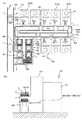
図1(a)は、本発明の搬送システムの一例を示す全体配置図、(b)は(a)の要部断面図である。
この搬送システム50は、半導体基板や液晶表示板などを製造する工場において、その素材となる平板状ワーク(半導体ウエハや、ガラス板)にクリーンルーム内で種々の加工処理を施す際に、平板状ワークを一枚ずつトレイに収容した状態で複数枚単位で、又は、一枚単位で搬送するものである。FIG. 1A is an overall layout view showing an example of the transport system of the present invention, and FIG. 1B is a cross-sectional view of the main part of FIG.
This
なお、以下では、半導体基板を製造する工場において、円形の半導体ウエハである平板状ワークW(以下、単に「ワーク」とも言う。)を同様に円形形状のトレイ1に収容して取り扱う例を説明するが、本発明の対象とする平板状ワーク、トレイの形状などはこれらに限定されるものではない。 In the following, an example in which a flat workpiece W (hereinafter also simply referred to as “work”), which is a circular semiconductor wafer, is accommodated in the
搬送システム50は、ワークWを一枚ずつ収容したトレイ1と、このトレイ1を複数段積みしたものを載置する底蓋2と、このトレイ1を複数段積みした状態の底蓋2に対して気密に上方から設置される上殻3(底蓋2と上殻3とから構成されるトレイ収納容器をポッド5とする。)と、このポッド5を搬送するポッド搬送手段10と、複数段積みされたトレイをポッドに対して出し入れするトレイ出し入れ手段20と、トレイを搬送するトレイ搬送手段30と、トレイ段積み段ばらし手段40とを備えている。 The
図中で、符号Sは、この搬送システム50が設置され、半導体製造工程の各加工処理のうちの一つを受け持つ加工処理ステーションであり、図中下段左端より、反時計回りに各ステーションを、S(1)、・・・、S(4)、S(5)などと表記する。
この加工処理ステーションSでは、トレイ1からワークWを取り出して、所定の加工処理を施したのち、また、トレイ1に戻すようにしている。
トレイ1、底蓋2と上殻3とから構成されるポッド5については、図2を用いて後に詳述する。In the figure, reference numeral S denotes a processing station in which the
In the processing station S, the workpiece W is taken out from the
The
ポッド搬送手段10は、各加工処理工程間を、ある程度のまとまりをもってワークW、つまり、トレイ1を搬送するもので、具体的には、上述したように、ワークWを一枚づつ収容したトレイ1を複数段積みしたもの1Mを収容したポッド5を搬送するものである。
このポッド搬送手段10は、床面走行の台車タイプであって、決められた走行路6と、この走行路7を自動制御されて走行する複数の台車7とを備えている。The pod conveying means 10 conveys the workpiece W, that is, the
The pod conveying means 10 is a floor type trolley type, and includes a predetermined traveling path 6 and a plurality of trolleys 7 that automatically travel along the traveling path 7.
したがって、このポッド搬送手段10は、工程間搬送スペースC1という、クリーン度の比較的低いクリーン環境の中で用いられるものであるが、ワークWとトレイ1は、気密なポッド5に収容された状態で搬送されるので、クリーン度の低い工程間搬送スペースC1中のパーテイクル(ダストなどの粒子を言う。)に汚染されることがない。
なお、ポッド搬送手段としては、ここでは床面走行の台車タイプを例示したが、これに限らず、天井走行タイプや、コンベア式であってもよい。
トレイ出し入れ手段20については、図3を用いて、後に詳述する。Therefore, the pod transfer means 10 is used in a clean environment having a relatively low cleanness, that is, the inter-process transfer space C1, but the work W and the
In addition, as a pod conveyance means, although the floor type trolley | bogie type was illustrated here, it is not restricted to this, A ceiling traveling type and a conveyor type may be sufficient.
The tray loading / unloading means 20 will be described in detail later with reference to FIG.
トレイ搬送手段30は、各加工処理ステーションS(1)〜S(8)にトレイ1を搬送するトレイ搬送手段30Aと、トレイ段積み段ばらし手段40からトレイ搬送手段30Aへトレイ1を搬送するトレイ搬送手段30Bと、トレイ搬送手段30Aからトレイ段積み段ばらし手段40へとトレイ1を搬送するトレイ搬送手段30Cとを備えている。 The tray conveying means 30 includes a tray conveying means 30A for conveying the
このトレイ搬送手段30は、ローラコンベアや、ベルトコンベアなどを用いると良いが、これらの限らず、クリーン環境下で、トレイ1を曲線部を含めてスムーズに搬送できるものであれば良い。
なお、トレイ搬送手段30で搬送するトレイ1は、一枚ずつであってもよく(枚葉搬送)、複数段積みされた状態であっても良い。
トレイ段積み段ばらし手段40については、図4を用いて、後に詳述する。The tray conveying means 30 may be a roller conveyor or a belt conveyor. However, the tray conveying means 30 is not limited thereto, and may be any one that can smoothly convey the
Note that the
The tray stacking and spreading
なお、トレイ出し入れ手段20、トレイ搬送手段30、トレイ段積み段ばらし手段40が設けられたスペースは、各加工処理ステーションS(1)〜S(8)内と同様に、ポッド搬送手段10が設けられたクリーン度の低い工程間搬送スペースC1に比べて、よりクリーン度の高い空間であり、工程内搬送スペースC0と称する。 The space where the tray loading / unloading means 20, the
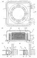
図2(a)は、図1のポッドの横断面を概念的に示す図、(b)は(a)の縦断面を概念的に示す図、(c)は(a)のポッドの底蓋閉止状態の要部詳細図、(d)は同底蓋開放状態の要部詳細図である。これより既に説明した部分には、同じ符号を付して重複説明を省略する。 2A is a diagram conceptually showing a transverse section of the pod of FIG. 1, FIG. 2B is a diagram conceptually showing a longitudinal section of FIG. 1A, and FIG. 2C is a bottom lid of the pod of FIG. The principal part detailed drawing of a closed state, (d) is the principal part detailed drawing of the bottom cover open state. The parts already described above are denoted by the same reference numerals and redundant description is omitted.
ポッド5を構成する底蓋2は、正方形の板状であり、その上に複数段積みされたトレイ1を載置することが出来、その4辺外縁にそって、エアーチューブシール手段4が設けられている。 The
エアーチューブシール手段4は、前記4辺外縁に沿って、一辺の一部が開口した四角筒を巻き付けた収容筒体4aと、この収容筒体4aに収容され、収縮・膨張するエアーチューブ4bと、このエアーチューブ4bの収縮・膨張に伴って、その突起部4dが収容筒体4aの開口部分対して、内側位置と突出した位置とに移動するシール体4cとを備えている。 The air tube sealing means 4 includes an
底蓋2の下側、つまり、トレー1を載置する側とは反対側には、ポッド5を上下に積み重ねる際に、ポッド5相互間の水平方向の位置決めをするための嵌め込み凹所2aが設けられている。この嵌め込み凹所2aは、ポッド5を上下に積み重ねる必要がない場合には、不要のものである。 On the lower side of the
上殻3は、トレイ1収納状態のポッド5を上下に積み重ねても耐え得る強度を持った構造体であり、また、それ自身、気密を維持できるものである。
上殻3の下部開口部は、エアーチューブシール手段4を含めた底蓋2の外縁に沿う形状ではあるが、この下部開口部内縁と、蓋2の外縁との間には、自由な空気の流通を阻止しない程度の隙間があり、この隙間は、エアーチューブシール手段4によって開閉されるようになっている。The
The lower opening of the
上殻3の上縁には、上記底蓋2の嵌め込み凹所2aに対応して、ポッド5を上下に積み重ねる際に、ポッド5相互間の水平方向の位置決めをするための嵌め込み凸所3aが設けられている。この嵌め込み凸所3aも、ポッド5を上下に積み重ねる必要がない場合には、不要のものである。 On the upper edge of the
上殻3の側面には、外側に張り出した取手5aが設けられている。この取手5aは、底蓋2以外の部分で、ポッド5を持ち上げたりする場合に用いられるもので、例えば、収容したトレイ1を含めたポッド5の重量がそれほど重くない場合には、現場で、人手で持ち上げるのに都合が良い。しかしながら、この取手5aは、その必要がない場合には不要のものである。 On the side surface of the
上殻3の高さは、ポッド5の中に収容すべきトレイ1の段積み枚数に対応させて自由に変えることができる。この際、底蓋2(エアーチューブシール手段4を含む。)との間には上記隙間があるので、同じ底蓋2にどの上殻3でも使用可能で、底蓋2に依存しないで、その高さを変えることができ、ポッド5の高さ、つまり、トレイ1の収容枚数の自由度が高くなる。 The height of the
このような自由度の高さは、従来用いられていた、トレイを用いずに、ワークを載置する複数の棚板を設けた側面開口式のカセットでは、対応不可能なものである。 Such a high degree of freedom cannot be handled by a side-opening type cassette provided with a plurality of shelves on which a work is placed without using a tray.
また、ここで用いるトレイ1は、図4で後述するような構造により、上記従来方式のカセットに比べ、ワークW間の積み上げ高さを数分の一程度に小さくすることができるものであり、従来の同じ枚数のワークWを収容するための、上殻3の高さを数分の一程度とすることができる。 In addition, the
ここで、本発明の搬送システムの発明者は、このようなトレイ1の特徴を生かして、単に上殻3の高さを従来のカセットと同様にして、トレイ1(ひいては、ワークW)の収容枚数を増やすのではなく、より少ない枚数を基本単位として、一つのポッド5に収容可能として、多量搬送の場合には、このポッド5自身を、上述の嵌め込み凹所2a、嵌め込み凸所3aなどを設けて、多段積み上げ可能とすることを着想したものである。 Here, the inventor of the transport system of the present invention takes advantage of the characteristics of the
そのようにすると、より小分けの搬送が可能であり、多品種小ロット対応が可能となり、搬送効率が向上する。
つまり、本発明のポッド5は、上記のようなトレイ1を複数段積み載置する底蓋2と、それに対して、エアーチューブシール手段4により互換性がありながら、機密性を保つ上殻3との組み合わせで、上記のように、多品種小ロット対応を可能とし、搬送効率を向上させることを可能とするものである。In such a case, it is possible to carry a smaller number of conveyances, to deal with a variety of small lots, and to improve the conveyance efficiency.
That is, the
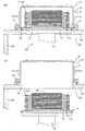
図3(a)、(b)は、図1のトレイ出し入れ手段の作用効果を説明する図である。
本発明においては、ポッド5から、トレイ1Mを出し入れするトレイ出し入れ手段20は、ポッド5自身が、上述したように、底蓋2にトレイ1を複数段積み載置し、上殻3に対しては、エアーチューブシール手段4によって、容易にシール解除と抵抗無く離脱が可能なものであるので、図1(b)でも解るように、トレイ出し入れ手段20は、この底蓋2を昇降させる非常に簡単な構造のもので足りる。FIGS. 3A and 3B are diagrams for explaining the operation and effect of the tray taking-in / out means of FIG.
In the present invention, the tray loading / unloading means 20 for loading / unloading the
ここでは、より具体的にその構造を示しており、トレイ出し入れ手段20は、通常、クリーンルームで用いることが可能な昇降手段12の上部に、ポッド5の底蓋2に合わせたポッド受板11を載置したものである。
ポッド受板11は、底蓋2に嵌め込み凹所2aがある場合には、これに嵌合する嵌め込み突起11aを設けるのがよく、その場合には、トレイ出し入れ手段20とポッド5との間の水平方向の位置決めがより確実になる。Here, the structure is shown more specifically, and the tray loading / unloading means 20 has a
If the
また、このトレイ出し入れ手段20は、クリーン度の低い工程間搬送スペースC1とクリーン度の高い工程内搬送スペースC0とを隔てる隔壁CAの水平部分に設けられ、その開口部13に、ポッド受板11が嵌まり込むようになっている。
この開口部13の周辺には、ここに載置されるポッド5の上殻3の下縁部分を押さえる、進退可能な押さえ板14が設けられている。Further, the tray taking-in / out means 20 is provided in a horizontal portion of the partition wall CA that separates the inter-process transport space C1 having a low cleanness from the intra-process transport space C0 having a high cleanness, and the
Around the
さて、このような構成のトレイ出し入れ手段20は、以下のように作用し、効果を発揮する。
隔壁CAのトレイ出し入れ手段20が設けられている部分に、ポッド5が載置されると、押さえ板14で上殻3が固定される。この状態は、トレイ出し入れ手段20のポッド受板11にポッド5の底蓋2が載置されている状態でもある。Now, the tray loading / unloading means 20 having such a configuration acts as follows and exhibits an effect.
When the
ついで、エアーチューブシール手段4によって、底蓋2と上殻3との間のシールが解除され、底蓋2が抵抗無く上殻3に対して離脱が可能な状態となる。この状態を示すのが図3(a)である。 Next, the seal between the
ここで昇降手段12によって、ポッド受板11を下げれば、図3(b)の状態となり、底蓋2上に段積みされたトレイ1Mは、取り出され、クリーン度の高い工程内搬送スペースC0内に収容された状態となる。つまり、このトレイ出し入れ手段20は、ごく容易にトレイ1をポッド5から出し入れすることができる。 If the
この際、底蓋2の下降に伴い、上殻3の下方開口が開放されることとなり、上殻3内が負圧となりやすくなるが、収縮したエアーチューブシール手段4と上殻3との間には空気の流通に抵抗を与えない程度の隙間があるので、この負圧発生を押さえることができ、まだ、上殻3内にあるトレイ1M、ひいてはそれぞれのトレイ1に収容されたワークWにこの負圧によって生じる気流に乗って付着する可能性のあるパーテイクルの付着を抑制することができる。 At this time, as the
また、この気流は、クリーン度の高い工程内搬送スペースC0側から発生するので、よりパーテイクルの影響を少なくすることができる。 Further, since this air flow is generated from the in-process conveyance space C0 having a high cleanliness, the influence of the particles can be further reduced.
つまり、本発明のポッド5と、これに対応したポッド搬送手段10とトレイ出し入れ手段20とによれば、上述のポッド5の効果と、上述のクリーン度の低い工程間搬送スペースC1におけるポッド搬送手段10の効果に加え、工程間搬送スペースC1から工程内搬送スペースC0へのトレイ出し入れ手段20の上記効果を併せ発揮し、全体として、トレイ単位での取扱の自動化を可能とし、クリーンな状態で、トレイ1を効率よく搬送することができる。 That is, according to the
なお、底蓋2が取り外された状態では、上殻3が、工程間搬送スペースC1と工程内搬送スペースC0との間の隔壁の役割を果たしており、両者間の空気の流通を阻止し、工程内搬送スペースC0のクリーン度が、工程間搬送スペースC1のクリーン度に影響されないようにしている。 In the state where the
また、この上殻3は、底蓋2に対して上述したように互換性があるので、この状態で待機して、加工処理が済んだトレイ1を複数段積みした底蓋2が準備できた場合には、その底蓋2がトレイ出し入れ手段20により持ち上げられて、この外殻3に収容されて、ポッド5として、ポッド搬送手段10の搬送対象となる。 Further, since the
こうして、本発明の互換性のある底蓋2と、上殻3とを組み合わせたポッド5と、この底蓋2だけを昇降させるトレイ出し入れ手段20との組み合わせで、その互換性を利用した、柔軟性の高い搬送が可能となっている。 In this way, the combination of the
図4(a)は、図1のトレイ段積み段ばらし手段の平面図、(b)は(a)の側面図、(c)はトレイ段積み段ばらし手段がトレイを把持した状態の要部断面図である。 4A is a plan view of the tray stacking and separating means in FIG. 1, FIG. 4B is a side view of FIG. 1A, and FIG. 4C is a main part in a state where the tray stacking and separating means grips the tray. It is sectional drawing.
このトレイ段積み段ばらし手段40は、トレイ1を一枚ずつ把持可能な一対のトレイ把持手段31と、この一対のトレイ把持手段31をその対向距離を可変に保持するスライド保持手段32と、スライド保持手段32を方向制御可能に、その一端に設置したフリーアーム33と、このフリーアーム33の基端を昇降可能に支持する昇降手段34とを備えている。 The tray stacking and separating means 40 includes a pair of tray holding means 31 that can hold the
また、このトレイ段積み段ばらし手段40は、段積みされたトレイを載置した底蓋2を昇降可能に載置する底蓋昇降手段35を備えているが、トレイ把持手段31側が昇降可能であれば、この底蓋昇降手段35は、昇降可能なものでなくとも良い。 The tray stacking and spreading
ここで、トレイ段積み段ばらし手段40を適用可能な本発明のトレイ1の要部構成について、図4(c)を用いて説明する。このトレイ1は、本出願人による先願:特願2005−214156号に記載されたトレイの要部を受け継ぐものである。 Here, the configuration of the main part of the
このトレイ1は、全体として、すそ広がりの円錐台形形状の鍔付き帽子様の形状をしており、その上辺部1aの上ににワークWを載置し、斜辺部1bで全体の構造的強度を保持し、下辺裾部1cでトレイ1の把持を可能とし、この下辺裾部1cに積み上げブロック体1dを組み付けたものである。 The
積み上げブロック体1dは、積み重ねるべき上下のトレイ1の積み上げブロック体1dとの位置決めのための嵌合突起1e及び嵌合凹部1fと、上下のブロック体1d間に所定の隙間を与える把持切欠部1gを備えている。 The
このトレイ1は、その積み上げについては、その上積みされるトレイ1の荷重を積み上げブロック体1dだけで受けるので、このトレイ1に載置されたワークWには全然影響を与えない。 When the
傾斜部1bでトレイ1の強度を保持しながら、この傾斜部1bが上下のトレイ1で相互に嵌まり込むので、ワークWの積み上げた高さH1をトレイ1自身の高さH0より小さくできる。 While maintaining the strength of the
傾斜部1bでトレイ1の強度が保持され、積み上げブロック体1dには把持切欠部1gがあるので、この部分に、トレイ把持手段31の把持突起31a、31bを嵌まり込ませるだけで、トレイ1を変形させずに、ひいては、トレイ1に載置されたワークWに悪影響を与えることなく、トレイ1を一つだけ把持することができる。 The strength of the
また、この際、把持したトレイ1の上に複数トレイ1が段積みされている場合でも、その影響を受けることなく、段積みされたままで、トレイ1を把持することができる。 At this time, even when a plurality of
更に、このような把持の方法が可能になることで、ワークWを直接把持する場合には、その変形を少なくするため、ワークWの全面を載せるように取り出し手段を出し入れする必要から、ワークWの上下間にそのための隙間が必要であったのが、そのような隙間が全く必要なくなっている。 Furthermore, since such a gripping method becomes possible, when the workpiece W is directly gripped, in order to reduce the deformation, it is necessary to put in and take out the take-out means so that the entire surface of the workpiece W is placed. However, such a gap is not necessary at all.
結果として、上述したように、このトレイ1を用いた場合、従来の直接ワークWを各段に載置するカセットに比べ、積み上げ高さを数分の一とすることができるのである。 As a result, as described above, when this
さて、上記の説明から自明のことであるが、このようなトレイ1を、トレイ段積み段ばらし手段40で段積み、段ばらしする場合には、トレイ把持手段31を所定の高さとし、その把持突起31a、31bがトレイ1の把持切欠部1gに入り込むようにして、一枚ずつトレイ1を把持した後、段積みし、段ばらしすれば良い。 As is obvious from the above description, when stacking and stacking
この際、把持したトレイ1の上に段積みされているトレイ1の枚数によれば、2枚単位、3枚単位など任意の枚数で、段積み、段ばらしが可能である。 At this time, according to the number of
このトレイ段積み段ばらし手段40は、トレイ搬送手段30とポッド搬送手段10との間に設けられているので、結果として、必要に応じて、トレイ1単位の搬送(一枚ずつの枚葉搬送を含む。)と、ポッド5によるバルク搬送(一定量纏めた搬送)を選択することができる。 Since the tray stacking and separating means 40 is provided between the
なお、トレイ段積み段ばらし手段40で、段積みされたトレイ1Mから、任意の上下位置のトレイ1を選択的に段ばらししたい場合には、トレイ段積み段ばらし手段40を更に一台設置して、不要な上段の複数のトレイ1を一方のトレイ段積み段ばらし手段40で取り上げた後に、他方のトレイ段積み段ばらし手段40で必要な段数のトレイ1を把持し、段ばらしすればよい。 When the tray stacking / unloading means 40 is used to selectively stack the
あるいは、一台の場合には、仮置き場所を作り、一時不要なトレイ1を退避させてから、必要なトレイ1を段ばらしするようにすればよい。 Alternatively, in the case of a single unit, a temporary storage place may be created and the
なお、本発明の搬送システムの発明思想は、従来、搬送側としては、クリーン度の低い工程間搬送スペースC1内に守備範囲が限定されていたのを、全体としての搬送のクリーン度の向上と効率化を図るため、その守備範囲をクリーン度の高い工程内搬送スペースC0にまで及ばせた点にも表れており、この点では、従来の搬送システムの殻を破る画期的なものである。 The inventive concept of the transport system according to the present invention is that, on the transport side, the defensive range has been limited in the inter-process transport space C1 with a low cleanness, and the overall cleanness of the transport is improved. In order to improve efficiency, it also appears that the range of defense has been extended to the in-process transport space C0 with a high degree of cleanliness, and this is a breakthrough that breaks the shell of conventional transport systems. .
以上、実施例において本発明の具体例を詳細に説明したが、これらは例示にすぎず、特許請求の範囲を限定するものではない。特許請求の範囲に記載の技術、つまり、本願特許発明の技術的範囲には、各所に適宜記載しているように、以上に例示した具体例を様々に変形、変更したものが含まれる。 As mentioned above, although the specific example of this invention was described in detail in the Example, these are only illustrations and do not limit a claim. The technology described in the claims, that is, the technical scope of the patented invention of the present application includes various modifications and alterations of the specific examples illustrated above as appropriately described in various places.
本発明の搬送システムは、クリーン度を維持しながら、トレイ単位での取扱の自動化、多品種小ロットへの対応、搬送効率の向上を可能とすることが要請される産業分野に用いることができる。 The conveyance system of the present invention can be used in industrial fields that are required to be able to automate handling in units of trays, handle various types of small lots, and improve conveyance efficiency while maintaining cleanliness. .
1 トレイ
2 底蓋
3 上殻
5 ポッド
10 ポッド搬送手段
20 トレイ出し入れ手段
30 トレイ搬送手段
40 トレイ段積み段ばらし手段
50 搬送システム1 tray
2 Bottom cover
3 Upper shell
DESCRIPTION OF
Claims (2)
Translated fromJapanese前記ポッド搬送手段は、工程間搬送スペースでポッドを搬送するものであり、前記トレイ搬送手段は、前記工程間搬送スペースよりクリーン度の高い工程内搬送スペースで並設されている複数の加工処理ステーションに対してトレイを搬送するものであり、
前記工程内搬送スペースと前記工程間搬送スペースとの境界上に、前記ポッド搬送手段で搬送されたポッドが載置され、
前記境界上に載置されたポッドに複数段積みされたトレイを該ポッドから、前記工程間搬送スペースに対して出し入れするトレイ出し入れ手段を備え、前記トレイ段積み段ばらし手段は、前記トレイ出し入れ手段と前記トレイ搬送手段との間に設けられ、
前記ポッドは、段積みされたトレイを載せる底蓋と、この段積みされトレイを載せた底蓋を上方から覆う上殻とを備え、前記トレイ出し入れ手段は、工程間搬送スペース側である前記上殻に対して、前記底蓋を工程内搬送スペース側との間で上下させるものであり、このトレイ出し入れ手段による前記底蓋の上下の間、前記上殻は、前記工程間搬送スペースと前記工程内搬送スペースとを遮蔽する搬送システム。Pod transport means for transporting pods in which a plurality of stacked trays are hermetically contained , tray transport means for transporting trays, and stacking of multiple trays between the tray transport means and the pod transport means, or Providing tray stacking and stacking means for stacking multiple stacked trays;
The pod transfer means is for transferring a pod in an inter-process transfer space, and the tray transfer means is a plurality of processing stations arranged in parallel in an in-process transfer spacehaving a higher cleanliness than the inter- process transfer space. To transport the tray against
On the boundary between the intra-process transport space and the inter-process transport space, the pod transported by the pod transport means is placed,
Tray loading / unloading means for loading and unloading a plurality of trays stacked on the pod placed on the boundary with respect to the inter-process transport space is provided from the pod, and the tray stacking and unloading means includes the tray loading / unloading means. And the tray conveying means,
The pod includes a bottom lid on which the stacked trays are placed, and an upper shell that covers the bottom lid on which the stacked trays are placed from above, and the tray loading / unloading means is the inter-process transport space side. The bottom lid is moved up and down with respect to the shell with respect to the in-process conveyance space side, and the upper shell is moved between the inter-process conveyance space and the process between the top and bottom of the bottom lid by the tray taking-in / out means. A transfer systemthat shields the inner transfer space .
Priority Applications (6)
| Application Number | Priority Date | Filing Date | Title |
|---|---|---|---|
| JP2006164324AJP4333701B2 (en) | 2006-06-14 | 2006-06-14 | Transport system |
| KR1020070013665AKR20070119480A (en) | 2006-06-14 | 2007-02-09 | Conveying system |
| TW096105099ATW200806554A (en) | 2006-06-14 | 2007-02-12 | Conveying system |
| EP07006599AEP1867591A1 (en) | 2006-06-14 | 2007-03-29 | Conveying system |
| US11/730,768US20070292256A1 (en) | 2006-06-14 | 2007-04-04 | Conveying system |
| CNA2007101100045ACN101088893A (en) | 2006-06-14 | 2007-06-14 | Conveying system |
Applications Claiming Priority (1)
| Application Number | Priority Date | Filing Date | Title |
|---|---|---|---|
| JP2006164324AJP4333701B2 (en) | 2006-06-14 | 2006-06-14 | Transport system |
Publications (2)
| Publication Number | Publication Date |
|---|---|
| JP2007335555A JP2007335555A (en) | 2007-12-27 |
| JP4333701B2true JP4333701B2 (en) | 2009-09-16 |
Family
ID=38017068
Family Applications (1)
| Application Number | Title | Priority Date | Filing Date |
|---|---|---|---|
| JP2006164324AExpired - Fee RelatedJP4333701B2 (en) | 2006-06-14 | 2006-06-14 | Transport system |
Country Status (6)
| Country | Link |
|---|---|
| US (1) | US20070292256A1 (en) |
| EP (1) | EP1867591A1 (en) |
| JP (1) | JP4333701B2 (en) |
| KR (1) | KR20070119480A (en) |
| CN (1) | CN101088893A (en) |
| TW (1) | TW200806554A (en) |
Families Citing this family (4)
| Publication number | Priority date | Publication date | Assignee | Title |
|---|---|---|---|---|
| US9545724B2 (en)* | 2013-03-14 | 2017-01-17 | Brooks Automation, Inc. | Tray engine with slide attached to an end effector base |
| CN106946012B (en)* | 2017-03-22 | 2023-02-14 | 武汉工程大学 | An automatic offline machine and its automatic control method |
| CN109110497B (en) | 2018-08-31 | 2021-06-11 | 惠科股份有限公司 | Conveying system and conveying method for display panel |
| US11705358B2 (en)* | 2018-10-29 | 2023-07-18 | Taiwan Semiconductor Manufacturing Co., Ltd. | Systems and methods for automated processing ports |
Family Cites Families (22)
| Publication number | Priority date | Publication date | Assignee | Title |
|---|---|---|---|---|
| US2656048A (en)* | 1951-06-22 | 1953-10-20 | Nat Plastic Products Company | Apparatus for loading and unloading laminating presses |
| US4014430A (en)* | 1970-12-28 | 1977-03-29 | B & K Hydraulic Co. | Automatic palletizer method and apparatus |
| US4034846A (en)* | 1975-04-25 | 1977-07-12 | Bunting Magnetics Company | Method and apparatus for providing automatic stacking of manufactured parts |
| US4582219A (en)* | 1985-02-20 | 1986-04-15 | Empak, Inc. | Storage box having resilient fastening means |
| US4865515A (en)* | 1987-06-24 | 1989-09-12 | Dorner Mfg. Corp. | Apparatus for unstacking and stacking containers |
| US5380138A (en)* | 1987-08-07 | 1995-01-10 | Canon Kabushiki Kaisha | Automatic article feeding system |
| US5010716A (en)* | 1989-08-18 | 1991-04-30 | Fassauer Arthur L | Air-floated cutting apparatus with overhead grass catcher |
| US5313156A (en)* | 1991-12-04 | 1994-05-17 | Advantest Corporation | Apparatus for automatic handling |
| US5290141A (en)* | 1992-11-06 | 1994-03-01 | Brenton Engineering Inc. | Continuous down stacker apparatus |
| US5478202A (en)* | 1994-03-07 | 1995-12-26 | Ishii; Toru | Case separating apparatus |
| EP0735573B1 (en)* | 1995-03-28 | 2004-09-08 | BROOKS Automation GmbH | Loading and unloading station for semiconductor treatment installations |
| US5674039A (en)* | 1996-07-12 | 1997-10-07 | Fusion Systems Corporation | System for transferring articles between controlled environments |
| US5885045A (en)* | 1997-03-17 | 1999-03-23 | Fortrend Engineering Corporation | Integrated wafer pod-load/unload and mass-transfer system |
| JP3591679B2 (en)* | 1997-04-17 | 2004-11-24 | 株式会社アドバンテスト | IC tray removal device and IC tray storage device |
| US6579052B1 (en)* | 1997-07-11 | 2003-06-17 | Asyst Technologies, Inc. | SMIF pod storage, delivery and retrieval system |
| CA2318548A1 (en)* | 1998-01-16 | 1999-07-22 | Discovery Technologies Ag | Method and device for conducting a large number of identical biological/chemical tests on the microscale |
| US5997238A (en)* | 1998-10-13 | 1999-12-07 | Sony Corporation | On-line package stacking apparatus and method |
| JP4202498B2 (en)* | 1998-12-15 | 2008-12-24 | 株式会社アドバンテスト | Parts handling device |
| EP1644959B1 (en)* | 2003-07-11 | 2013-09-11 | Tec-Sem AG | Device for storing and/or transporting plate-shaped substrates in the manufacture of electronic components |
| JP4337683B2 (en)* | 2004-08-16 | 2009-09-30 | 村田機械株式会社 | Transport system |
| TWI280220B (en)* | 2004-10-25 | 2007-05-01 | Tokyo Electron Ltd | Carrying system, substrate treating device, and carrying method |
| JP4367440B2 (en)* | 2006-06-14 | 2009-11-18 | 村田機械株式会社 | Transport system |
- 2006
- 2006-06-14JPJP2006164324Apatent/JP4333701B2/ennot_activeExpired - Fee Related
- 2007
- 2007-02-09KRKR1020070013665Apatent/KR20070119480A/ennot_activeWithdrawn
- 2007-02-12TWTW096105099Apatent/TW200806554A/enunknown
- 2007-03-29EPEP07006599Apatent/EP1867591A1/ennot_activeWithdrawn
- 2007-04-04USUS11/730,768patent/US20070292256A1/ennot_activeAbandoned
- 2007-06-14CNCNA2007101100045Apatent/CN101088893A/enactivePending
Also Published As
| Publication number | Publication date |
|---|---|
| CN101088893A (en) | 2007-12-19 |
| JP2007335555A (en) | 2007-12-27 |
| US20070292256A1 (en) | 2007-12-20 |
| EP1867591A1 (en) | 2007-12-19 |
| KR20070119480A (en) | 2007-12-20 |
| TW200806554A (en) | 2008-02-01 |
Similar Documents
| Publication | Publication Date | Title |
|---|---|---|
| JP4367440B2 (en) | Transport system | |
| US11978652B2 (en) | Automatic handling buffer for bare stocker | |
| CN112786504B (en) | Substrate processing device and substrate storage container storage method | |
| KR20140089517A (en) | Load port and efem | |
| KR100288852B1 (en) | semiconductor accomodating jig, handling method production system | |
| JP3632812B2 (en) | Substrate transfer equipment | |
| JP4333701B2 (en) | Transport system | |
| KR20090064587A (en) | Board Storage | |
| JP4348520B2 (en) | Transport system | |
| TW201348100A (en) | Conveyance system | |
| KR20060133448A (en) | Conveying system | |
| JP2010241547A (en) | Traveling vehicle system | |
| JP2006347752A (en) | Conveyance system | |
| JP5277572B2 (en) | Plate-like material storage and transfer system and plate-like material storage and transfer method | |
| JP2005170682A (en) | Display substrate take-out mechanism and display substrate take-out method | |
| TWI741028B (en) | Article transport facility | |
| HK1110569A (en) | Conveying system | |
| EP2245656B1 (en) | Automatic handling buffer for bare stocker | |
| JP2008100802A (en) | Substrate storage warehouse | |
| CN222715445U (en) | Coating device | |
| JP4269222B2 (en) | Tray transport system | |
| JP2008010567A (en) | Pod for carrying article for use in clean room and article carrying system adopting it | |
| JP2005093585A (en) | Tray and its transfer system thereof | |
| JP2008100801A (en) | Substrate storage warehouse | |
| CN119546798A (en) | Coating device |
Legal Events
| Date | Code | Title | Description |
|---|---|---|---|
| A977 | Report on retrieval | Free format text:JAPANESE INTERMEDIATE CODE: A971007 Effective date:20080404 | |
| A131 | Notification of reasons for refusal | Free format text:JAPANESE INTERMEDIATE CODE: A131 Effective date:20080430 | |
| A521 | Written amendment | Free format text:JAPANESE INTERMEDIATE CODE: A523 Effective date:20080624 | |
| RD02 | Notification of acceptance of power of attorney | Free format text:JAPANESE INTERMEDIATE CODE: A7422 Effective date:20080624 | |
| A02 | Decision of refusal | Free format text:JAPANESE INTERMEDIATE CODE: A02 Effective date:20090217 | |
| A521 | Written amendment | Free format text:JAPANESE INTERMEDIATE CODE: A523 Effective date:20090416 | |
| A911 | Transfer to examiner for re-examination before appeal (zenchi) | Free format text:JAPANESE INTERMEDIATE CODE: A911 Effective date:20090423 | |
| TRDD | Decision of grant or rejection written | ||
| A01 | Written decision to grant a patent or to grant a registration (utility model) | Free format text:JAPANESE INTERMEDIATE CODE: A01 Effective date:20090602 | |
| A01 | Written decision to grant a patent or to grant a registration (utility model) | Free format text:JAPANESE INTERMEDIATE CODE: A01 | |
| A61 | First payment of annual fees (during grant procedure) | Free format text:JAPANESE INTERMEDIATE CODE: A61 Effective date:20090615 | |
| FPAY | Renewal fee payment (event date is renewal date of database) | Free format text:PAYMENT UNTIL: 20120703 Year of fee payment:3 | |
| R150 | Certificate of patent or registration of utility model | Free format text:JAPANESE INTERMEDIATE CODE: R150 | |
| FPAY | Renewal fee payment (event date is renewal date of database) | Free format text:PAYMENT UNTIL: 20130703 Year of fee payment:4 | |
| R250 | Receipt of annual fees | Free format text:JAPANESE INTERMEDIATE CODE: R250 | |
| LAPS | Cancellation because of no payment of annual fees |