JP4333367B2 - Roll sheet holder and tape printer - Google Patents
Roll sheet holder and tape printerDownload PDFInfo
- Publication number
- JP4333367B2 JP4333367B2JP2004001036AJP2004001036AJP4333367B2JP 4333367 B2JP4333367 B2JP 4333367B2JP 2004001036 AJP2004001036 AJP 2004001036AJP 2004001036 AJP2004001036 AJP 2004001036AJP 4333367 B2JP4333367 B2JP 4333367B2
- Authority
- JP
- Japan
- Prior art keywords
- roll sheet
- holder
- sheet
- positioning
- roll
- Prior art date
- Legal status (The legal status is an assumption and is not a legal conclusion. Google has not performed a legal analysis and makes no representation as to the accuracy of the status listed.)
- Expired - Fee Related
Links
Images


Classifications
- B—PERFORMING OPERATIONS; TRANSPORTING
- B41—PRINTING; LINING MACHINES; TYPEWRITERS; STAMPS
- B41J—TYPEWRITERS; SELECTIVE PRINTING MECHANISMS, i.e. MECHANISMS PRINTING OTHERWISE THAN FROM A FORME; CORRECTION OF TYPOGRAPHICAL ERRORS
- B41J15/00—Devices or arrangements of selective printing mechanisms, e.g. ink-jet printers or thermal printers, specially adapted for supporting or handling copy material in continuous form, e.g. webs
- B41J15/04—Supporting, feeding, or guiding devices; Mountings for web rolls or spindles
- B—PERFORMING OPERATIONS; TRANSPORTING
- B41—PRINTING; LINING MACHINES; TYPEWRITERS; STAMPS
- B41J—TYPEWRITERS; SELECTIVE PRINTING MECHANISMS, i.e. MECHANISMS PRINTING OTHERWISE THAN FROM A FORME; CORRECTION OF TYPOGRAPHICAL ERRORS
- B41J15/00—Devices or arrangements of selective printing mechanisms, e.g. ink-jet printers or thermal printers, specially adapted for supporting or handling copy material in continuous form, e.g. webs
- B41J15/02—Web rolls or spindles; Attaching webs to cores or spindles
- B—PERFORMING OPERATIONS; TRANSPORTING
- B41—PRINTING; LINING MACHINES; TYPEWRITERS; STAMPS
- B41J—TYPEWRITERS; SELECTIVE PRINTING MECHANISMS, i.e. MECHANISMS PRINTING OTHERWISE THAN FROM A FORME; CORRECTION OF TYPOGRAPHICAL ERRORS
- B41J15/00—Devices or arrangements of selective printing mechanisms, e.g. ink-jet printers or thermal printers, specially adapted for supporting or handling copy material in continuous form, e.g. webs
- B41J15/04—Supporting, feeding, or guiding devices; Mountings for web rolls or spindles
- B41J15/042—Supporting, feeding, or guiding devices; Mountings for web rolls or spindles for loading rolled-up continuous copy material into printers, e.g. for replacing a used-up paper roll; Point-of-sale printers with openable casings allowing access to the rolled-up continuous copy material
- B—PERFORMING OPERATIONS; TRANSPORTING
- B41—PRINTING; LINING MACHINES; TYPEWRITERS; STAMPS
- B41J—TYPEWRITERS; SELECTIVE PRINTING MECHANISMS, i.e. MECHANISMS PRINTING OTHERWISE THAN FROM A FORME; CORRECTION OF TYPOGRAPHICAL ERRORS
- B41J15/00—Devices or arrangements of selective printing mechanisms, e.g. ink-jet printers or thermal printers, specially adapted for supporting or handling copy material in continuous form, e.g. webs
- B41J15/04—Supporting, feeding, or guiding devices; Mountings for web rolls or spindles
- B41J15/046—Supporting, feeding, or guiding devices; Mountings for web rolls or spindles for the guidance of continuous copy material, e.g. for preventing skewed conveyance of the continuous copy material
- B—PERFORMING OPERATIONS; TRANSPORTING
- B41—PRINTING; LINING MACHINES; TYPEWRITERS; STAMPS
- B41J—TYPEWRITERS; SELECTIVE PRINTING MECHANISMS, i.e. MECHANISMS PRINTING OTHERWISE THAN FROM A FORME; CORRECTION OF TYPOGRAPHICAL ERRORS
- B41J3/00—Typewriters or selective printing or marking mechanisms characterised by the purpose for which they are constructed
- B41J3/407—Typewriters or selective printing or marking mechanisms characterised by the purpose for which they are constructed for marking on special material
- B41J3/4075—Tape printers; Label printers
- Y—GENERAL TAGGING OF NEW TECHNOLOGICAL DEVELOPMENTS; GENERAL TAGGING OF CROSS-SECTIONAL TECHNOLOGIES SPANNING OVER SEVERAL SECTIONS OF THE IPC; TECHNICAL SUBJECTS COVERED BY FORMER USPC CROSS-REFERENCE ART COLLECTIONS [XRACs] AND DIGESTS
- Y10—TECHNICAL SUBJECTS COVERED BY FORMER USPC
- Y10S—TECHNICAL SUBJECTS COVERED BY FORMER USPC CROSS-REFERENCE ART COLLECTIONS [XRACs] AND DIGESTS
- Y10S242/00—Winding, tensioning, or guiding
- Y10S242/912—Indicator or alarm
Landscapes
- Unwinding Webs (AREA)
- Handling Of Continuous Sheets Of Paper (AREA)
- Replacement Of Web Rolls (AREA)
- Storage Of Web-Like Or Filamentary Materials (AREA)
- Electronic Switches (AREA)
- Controlling Rewinding, Feeding, Winding, Or Abnormalities Of Webs (AREA)
- Printers Characterized By Their Purpose (AREA)
- Handling Of Sheets (AREA)
- Impression-Transfer Materials And Handling Thereof (AREA)
Abstract
Description
Translated fromJapanese本発明は、筒状の巻芯に巻回されたロールシートが回転可能に取付けられるロールシートホルダであって、該ロールシートを搬送するための搬送手段と、該ロールシートに印刷する印刷手段とを備えたテープ印刷装置内で着脱可能な状態で支持されるロールシートホルダに関するものである。また、テープ印刷装置内に当該ロールシートホルダが着脱可能に支持されるテープ印刷装置に関するものである。 The present invention is a roll sheet holder to which a roll sheet wound around a cylindrical winding core is rotatably attached, a conveying means for conveying the roll sheet, and a printing means for printing on the roll sheet; It is related with the roll sheet holder supported in the state which can be attached or detached in the tape printer provided with. The present invention also relates to a tape printer in which the roll sheet holder is detachably supported in the tape printer.
従来より、粘着シートに離形紙が張り合わされた長尺状のシートにサーマルヘッドを介して文字等を印刷するテープ印刷装置が種々提案されている。このようなテープ印刷装置では、巻芯に巻回されたロールシートと、この巻芯が回転可能に取付けられるロールシートホルダと、この複数種類のシート幅の各々のロールシートホルダをテープ印刷装置内で着脱可能に支持する支持機構と、このロールシートホルダからロールシートを引き出して搬送するための搬送手段とを備えているものがある。
例えば、テープ印刷装置に装着されるロールシートホルダの一例として、断熱性を有する材料で形成され、芯に巻回されたロール状の感熱記録紙を収納すると共に、その芯の両端を支持する機構と、その感熱記録紙を一端から引き出す記録紙引出口と、ケース体外面に形成されて収納されている感熱記録紙の種類を示す凹凸部と、から構成される記録紙収納ケースがある(例えば、特許文献1参照。)。Conventionally, various tape printers have been proposed that print characters and the like on a long sheet in which a release sheet is bonded to an adhesive sheet via a thermal head. In such a tape printer, a roll sheet wound around a core, a roll sheet holder to which the core is rotatably mounted, and each roll sheet holder having a plurality of types of sheet widths are arranged in the tape printer. And a support mechanism that is detachably supported, and a transport unit that pulls and transports the roll sheet from the roll sheet holder.
For example, as an example of a roll sheet holder to be mounted on a tape printing apparatus, a mechanism for storing roll-shaped thermal recording paper formed of a heat-insulating material and wound around a core and supporting both ends of the core And a recording paper storage case comprising a recording paper outlet through which the thermal recording paper is drawn from one end, and a concavo-convex portion indicating the type of thermal recording paper formed and stored on the outer surface of the case body (for example, , See Patent Document 1).
そして、このような構成の記録紙収納ケースによれば、画像記録をする場合、テープ印刷装置は、底面部に配置されたマイクロスイッチなどによって収納されている感熱記録紙の種類を判別してサーマルヘッドへの通電電力を調節し、装着された感熱記録紙に適切な濃度で画像を記録できる。
しかしながら、上述した従来の記録紙収納ケースが装着されたテープ印刷装置においては、該記録紙収納ケースが感熱記録紙の引き出しによって、その引き出し方向に回転して、マイクロスイッチなどを押下する記録紙収納ケース表面に形成された凸部の下端面部が浮き上がって該マイクロスイッチから離れてしまい、感熱記録紙に適切な濃度で画像記録ができない虞があるという問題がある。 However, in the above-described tape printing apparatus equipped with the conventional recording paper storage case, the recording paper storage case rotates in the pulling-out direction by pulling out the thermal recording paper and presses the micro switch or the like. There is a problem that the lower end surface portion of the convex portion formed on the surface of the case is lifted away from the microswitch, and there is a possibility that image recording cannot be performed with an appropriate density on the thermal recording paper.
そこで、本発明は、上述した問題点を解決するためになされたものであり、ロールシートホルダは、該ロールシートホルダに巻回されたロールシートの下端部に対向する位置にロールシートの種類を特定する特定部を設けると共に、テープ印刷装置の該ロールシートの下端部に対向する底面部にセンサ手段を設けることによって、この特定部の浮き上がり等を防止してロールシートの種類を確実に検出することができるロールシートホルダ及びテープ印刷装置を提供することを目的とする。 Therefore, the present invention has been made to solve the above-described problems, and the roll sheet holder has a roll sheet type at a position facing the lower end of the roll sheet wound around the roll sheet holder. A specific part to be specified is provided, and a sensor means is provided on the bottom surface of the tape printing apparatus facing the lower end of the roll sheet, thereby preventing the specific part from being lifted and the like to reliably detect the type of the roll sheet. An object of the present invention is to provide a roll sheet holder and a tape printing apparatus that can handle the above.
前記目的を達成するため請求項1に係るロールシートホルダは、筒状の巻芯に巻回されるロールシートを搬送するための搬送手段と、該ロールシートに印刷する印刷手段とを備えたテープ印刷装置に使用され、前記テープ印刷装置内で着脱可能な状態で支持されるロールシートホルダにおいて、前記巻芯の筒孔の一端側から該筒孔の端縁部に嵌挿されると共に、前記ロールシートの一方の端面に当接される第1フランジ部が外側端面の外周部に形成される第1筒部材と、前記ロールシートの他方の端面に当接されると共に、内側面に前記巻芯の筒孔の他端側から該筒孔の端縁部に嵌挿される第2筒部材が内側面に立設される基準側保持部材と、前記第1筒部材に嵌挿されて一端側の外側端面の外周部に前記第1フランジ部の外側面に当接されて固着される第2フランジ部が形成されると共に、他端側が前記第2筒部材に嵌挿されて前記基準保持部材に固着される第3筒部材と、を備え、前記第1フランジ部は、前記第1筒部材の外側端面の下側外周面から下側方向に延出されて前記テープ印刷装置の底面部に当接する第1延出部を有し、前記基準側保持部材は、外側端面部の左右方向略中央部に上下方向縦長に突設される位置決めリブ部と、下端縁部からロールシートの最大外径時の下端部外周面に対向するように所定長さ延出される第2延出部と、前記第2延出部に形成されて、前記テープ印刷装置の底面部に配置された貫通孔の有無を検出する複数個のプランジャー式スイッチに対向する所定位置に穿設された複数の貫通孔の有無の組み合わせによって該ロールシートの種類を特定するロールシート特定部と、を有し、前記位置決めリブ部は、前記テープ印刷装置の上方に開口する正面視略縦長コの字状の第1位置決め溝部に嵌入されることにより位置決めされて着脱可能に支持されることを特徴とする。ここで、プランジャー式スイッチは、プランジャーとマイクロスイッチ等から構成される公知の機械式スイッチである。In order to achieve the above object, a roll sheet holder according to
このような特徴を有する請求項1に係るロールシートホルダは、ロールシートが巻回された巻芯の筒孔の一端側から該筒孔の端縁部に嵌挿されてロールシートの一方の端面に当接される第1筒部材と、該巻芯の筒孔の他端側から該筒孔の端縁部に嵌挿されロールシートの他方の端面に当接される基準側保持部材と、第1筒部材に嵌挿されて一端側がこの第1筒部材に固着されると共に他端側が基準保持部材に嵌挿されてこの基準保持部材に固着される第3筒部材と、から構成されている。また、第1筒部材は、外側端面の下側外周面から下側方向に延出されてテープ印刷装置の底面部に当接する第1延出部が形成されている。また、このロールシートホルダは、基準保持部材の外側端面部の左右方向略中央部に上下方向縦長に突設される位置決めリブ部が、テープ印刷装置の上方に開口する正面視略縦長コの字状の第1位置決め溝部に嵌入されると共に、該基準側保持部材の下端縁部からロールシートの最大外径時の下端部外周面に対向するように所定長さ延出される第2延出部が設けられている。また、この第2延出部には、テープ印刷装置の底面部に配置された貫通孔の有無を検出する複数個のプランジャー式スイッチに対向する所定位置に穿設された複数の貫通孔の有無の組み合わせによって、該ロールシートの種類を特定するロールシート特定部が形成されている。The roll sheet holder according to
また、請求項2に係るロールシートホルダは、請求項1に記載のロールシートホルダにおいて、前記第2延出部は、前記ロールシートの軸心の鉛直方向下方に配置されることを特徴とする。The roll sheet holder according to
また、請求項3に係るテープ印刷装置は、筒状の巻芯に巻回されるロールシートを搬送するための搬送手段と、該ロールシートに印刷する印刷手段と、前記ロールシートが巻回されるロールシートホルダを内部で着脱可能な状態で支持する支持機構と、を備えたテープ印刷装置において、前記ロールシートホルダは、請求項1又は請求項2に記載のロールシートホルダであり、前記支持機構は、底面部の一側側端縁部に立設されて前記第1位置決め溝部が形成される位置決め支持部材を有し、前記複数個のプランジャー式スイッチは、前記位置決め支持部材のロールシートホルダ側基端部に設けられていることを特徴とする。According to athird aspect of the present invention, there is provided a tape printing apparatus comprising: a conveying unit that conveys a roll sheet wound around a cylindrical core; a printing unit that prints on the roll sheet; and the roll sheet is wound. And a support mechanism for supporting the roll sheet holder in a detachable state inside the roll sheet holder, wherein the roll sheet holder is the roll sheet holder according to
このような特徴を有する請求項3に係るテープ印刷装置は、請求項1又は請求項2に記載のロールシートホルダを内部で着脱可能な状態で支持する支持機構が設けられている。また、このロールシートホルダのロールシートを搬送するための搬送手段と、該ロールシートに印刷する印刷手段とが設けられている。また、この支持機構は、底面部の一側側端縁部に立設されて第1位置決め溝部が形成される位置決め支持部材から構成されている。また、この位置決め支持部材のロールシートホルダ側基端部に、ロールシートの種類を特定する複数個のプランジャー式スイッチが設けられている。The tape printer according to
更に、請求項4に係るテープ印刷装置は、請求項3に記載のテープ印刷装置において、前記第2延出部に対向する底面部に形成されて該第2延出部が上方から嵌め込まれる凹部を有し、前記複数個のプランジャー式スイッチは、前記凹部に配置されていることを特徴とする。Furthermore, the tape printer according to
請求項1に係るロールシートホルダでは、基準側保持部材の外側端面部に突設される位置決めリブ部をテープ印刷装置の上方に開口する第1位置決め溝部に位置合わせして嵌入することによって、該基準保持部材の下端縁部からロールシートの最大外径時の下端部外周面に対向するように所定長さ延出される第2延出部に形成されたロールシート特定部を介して該ロールシートの種類が特定されるため、該ロールシート特定部が形成される第2延出部をロールシートの軸心の真下に配置することができ、このロールシートの自重によって複数個のプランジャー式スイッチ側方向に位置決めすることが可能となり、第2延出部の浮き上がり等を防止することができる。
また、基準保持部材の下端縁部からロールシートの最大外径時の下端部外周面に対向するように所定長さ延出されて第2延出部が設けられているため、該ロールシートの弾性復元力によってロールシートの巻回が少し緩んだ場合には、最外周面の下端部が第2延出部に当接して押さえられ、該ロールシートのばらけを確実に防止することができる。In the roll sheet holder according to
Further, since the second extending portion is provided to extend from the lower end edge of the reference holding member so as to face the outer peripheral surface of the lower end of the roll sheet at the maximum outer diameter, When the winding of the roll sheet is slightly loosened due to the elastic restoring force, the lower end portion of the outermost peripheral surface is pressed against the second extending portion, and the roll sheet can be reliably prevented from being scattered. .
また、請求項2に係るロールシートホルダでは、第2延出部が、ロールシートの軸心の鉛直方向下方に配置されていることから、ロールシートの自重が第2延出部にかかり、その自重により、第2延出部に形成されているロールシート特定部を複数個のプランジャー式スイッチ側方向に位置決めすることが可能となり、該第2延出部の複数個のプランジャー式スイッチからの浮き上がりを防止することができ、ロールシート判定部が複数個のプランジャー式スイッチから離れることを更に確実に防止することができる。Further, in the roll sheet holder according to
また、請求項3に係るテープ印刷装置では、位置決め支持部材のロールシートホルダ側基端部に、ロールシートホルダの第2延出部に形成されたロールシート特定部の貫通孔の有無によってロールシートの種類を特定する複数個のプランジャー式スイッチが設けられているため、この位置決め支持部材に形成される第1位置決め溝部に嵌入される位置決めリブ部を介して第2延出部のロールシート特定部が確実に位置決めされ、複数個のプランジャー式スイッチによる複数の貫通孔の有無の組み合わせの検出精度の向上を図ることができる。In the tape printer according to
更に、請求項4に係るテープ印刷装置では、第2延出部に対向する底面部に、該第2延出部が上方から嵌め込まれる凹部が形成されているため、該凹部内に第2延出部が嵌め込まれてロールシート特定部が固定される。このため、凹部に配置された複数個のプランジャー式スイッチを確実に動作させることが可能となり、複数個のプランジャー式スイッチによる複数の貫通孔の有無の組み合わせの検出精度の更なる向上を図ることができる。Furthermore, in the tape printer according to thefourth aspect , since the concave portion into which the second extending portion is fitted from above is formed on the bottom surface portion facing the second extending portion, the second extending portion is formed in the concave portion. The protruding portion is fitted and the roll sheet specifying portion is fixed. For this reason, it becomes possible to operatea plurality of plunger-type switches arranged in therecesses with certainty, andfurther improvethe detection accuracy of the combination of the presence or absence of a plurality of through-holes by the plurality of plunger-type switches. be able to.
以下、本発明に係るロールシートホルダ及びテープ印刷装置について、具体化した第1実施形態乃至第3実施形態に基づいて図面を参照しつつ詳細に説明する。 Hereinafter, a roll sheet holder and a tape printer according to the present invention will be described in detail with reference to the drawings based on the first to third embodiments.
先ず、第1実施形態に係るテープ印刷装置の概略構成について図1乃至図7に基づき説明する。
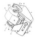
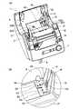
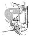
図1乃至図3に示すように、テープ印刷装置1は、本体筐体2と、所定幅のロールシート3Aが巻回されたロールシートホルダ3を収納するロールシートホルダ収納部4の上側を覆うように後側上端縁部に開閉自在(図14参照)に取り付けられた透明樹脂製の上カバー5と、この上カバー5の前側略中央部に対向するように立設される透明樹脂製のトレー6と、このトレー6の前側に配置される電源ボタン7と、前側側面部に左右移動可能に設けられてカッターユニット8(図7参照)を左右に移動させるカッターレバー9等から構成されている。また、本体筐体2の背面部には一方の側端部に電源コード10が接続されると共に、他方の側端部には不図示のパーソナルコンピュータ等と接続されるUSB(UniversalSerial Bus)等から構成されるコネクタ部11(図6参照)が設けられている。また、このロールシート3Aは、自己発色性を有する長尺状の感熱シート(いわゆる、サーマルペーパー)や、該感熱シートの片面に粘着剤を介して離形紙が張り合わされた長尺状のラベルシート等で構成され、巻芯3B(図4参照)に巻回されている。First, a schematic configuration of the tape printer according to the first embodiment will be described with reference to FIGS.
As shown in FIGS. 1 to 3, the
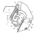
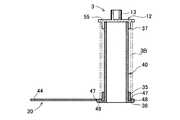
また、図2乃至図6に示すように、テープ印刷装置1は、ロールシートホルダ収納部4の搬送方向に対して略垂直方向の一方の側端縁部(図6中、左側側端縁部)に、後述のロールシートホルダ3を構成する位置決め保持部材12の外側方向に突設される断面略矩形状の取付部材13を嵌め込むことができるホルダ支持部材15が設けられている。このホルダ支持部材15には、上方に開口する正面視略縦長コの字状の第1位置決め溝部16が形成されている。また、このホルダ支持部材15の内側基端部には、位置決め保持部材12の下端部に突設される弾性係止片12Aが係合される係合凹部15Aが形成されている。 As shown in FIGS. 2 to 6, the
また、ロールシート3Aを挿入する挿入口18の後端縁部からロールシートホルダ収納部4の前側上端縁部まで略水平に延出されて、後述のロールシートホルダ3を構成するガイド部材20の先端部が載置される載置部21が設けられている。また、この載置部21の搬送方向後側の端縁角部には、ロールシート3Aの複数の幅寸法に対応して断面略L字状の4個の第2位置決め溝部22A〜22Dが形成されている。この各第2位置決め溝部22A〜22Dは、図7に示すように、ロールシートホルダ3を構成するガイド部材20の載置部21に当接する部分の一部を上方から嵌め込むことができるように形成されている。また、このロールシートホルダ3を構成するガイド部材20の先端部は、挿入口18まで延出されている。 Further, the
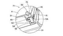
また、ロールシートホルダ収納部4の底面部には、ホルダ支持部材15の内側基端部から第2位置決め溝部22Aに対向する位置まで搬送方向に対して略垂直に平面視横長四角形の位置決め凹部4Aが所定深さ(第1実施形態では、約1.5〜3mmの深さである。)で形成されている。この位置決め凹部4Aの搬送方向幅寸法は、ロールシートホルダ3を構成する位置決め保持部材12及びガイド部材20の各下端縁部の幅寸法にほぼ等しくなるように形成されている。また、位置決め凹部4Aのホルダ支持部材15の内側基端部には、位置決め保持部材12の下端縁部から略直角内側方向に延出される後述のシート判別部60(図8〜図10参照)に対向する部分が、位置決め凹部4Aよりもさらに所定深さ(第1実施形態では、約1.5〜3mmの深さである。)だけ深くなるように形成された搬送方向に縦長の平面視長四角形の判別凹部4Bが形成されている。 In addition, the bottom surface portion of the roll sheet
また、この判別凹部4Bには、プッシュ式のマイクロスイッチ等から構成されて、ロールシート3Aの種別を判別するための5個のシート判別センサS1、S2、S3、S4、S5がL字状に設けられている。この各シート判別センサS1〜S5は、プランジャーとマイクロスイッチ等から構成される公知の機械式スイッチからなり、該各プランジャーの上端部は、該判別凹部4Bの底面部から位置決め凹部4Aの底面部近傍まで突き出るように設けられている。そして、この各シート判別センサS1〜S5に対してシート判別部60の後述の各センサ孔60A〜60E(図8参照)が有るか否かを検出して、そのオン・オフ信号によりロールシートホルダ3に装着されたロールシート3Aの種類を検出するものである。尚、第1実施形態の場合は、各テープ判別センサS1〜S5は、そのプランジャーが常には、判別凹部4Bの底面から位置決め凹部4Aの底面部近傍まで突き出しており、マイクロスイッチがオフ状態になっている。そして、シート判別部60の各センサ孔60A〜60Eが、各シート判別センサS1〜S5に対向する位置に有る場合には、プランジャーが押下されずマイクロスイッチがオフ状態にあるので、オフ信号が出力され、一方、シート判別部60の各センサ孔60A〜60Eが、各シート判別センサS1〜S5に対向する位置に無い場合には、プランジャーが押下されてマイクロスイッチがオン状態になるので、オン信号が出力される。 In addition, the determination
また、挿入口18のホルダー支持部材15側の側端縁部(図6中、左端縁部)は、該ホルダー支持部材15に嵌め込まれる位置決め部材12の内側端面に対向する位置に形成されている。また、この挿入口18のホルダー支持部材15側の側端縁部には、案内リブ部23が立設されている。 Further, the side edge (on the left edge in FIG. 6) of the
また、ロールシートホルダ収納部4の他方の側端縁部(図5中、左方の側端縁部)の搬送方向前端部には、サーマルヘッド31(図7参照)の上下動操作等を行うレバー27が設けられている。即ち、このレバー27を上方に回動させることにより、サーマルヘッド31が下方に移動されてプラテンローラ26(図7参照)から離間し、該レバー27を下方に回動させることにより、サーマルヘッド31が上方に移動されてロールシート3Aをプラテンローラ26に押圧付勢して印字可能な状態になる。また、ロールシートホルダ収納部4の下側には、外部のパーソナルコンピュータ等からの指令により各機構部を駆動制御する制御回路部が形成された制御基板32が設けられている。 Further, an operation of moving up and down the thermal head 31 (see FIG. 7) or the like is performed at the front end portion in the transport direction of the other side edge portion (left side edge portion in FIG. 5) of the roll sheet
これにより、巻芯3Bに巻回されたロールシート3Aが装着されたロールシートホルダ3は、位置決め部材12の取付部材13をホルダ支持部材15の第1位置決め溝部16に嵌め込み、該位置決め部材12の下端部に突設される弾性係止片12Aをホルダ支持部材15の内側基端部に形成される係合凹部15Aに係合させると共に、ガイド部材20の先端部下面を各第2位置決め溝部22A〜22Dに嵌め込んで該ガイド部材20の下端部を位置決め凹部4A内に嵌入して当接させることによって、ロールシートホルダ収納部4に着脱自在に取り付けられる。また、位置決め部材12の内側下端縁部に設けられたシート判別部60が判別凹部4B内に挿入され、判別凹部4Bに配設される各シート判別センサS1〜S5に対向する該シート判別部60の各センサ孔60A〜60Eが有るか否か検出可能となる。即ち、ロールシートホルダ3に装着されたロールシート3Aの種類を検出可能となる。
そして、レバー27を上方に回動させて、ロールシート3Aの一方の側端縁部をガイド部材20の内側面に当接させつつ、このロールシート3Aの他方の側端縁部を挿入口18の側縁部に立設される案内リブ部23に当接させながら挿入口18内に挿入して、該レバー27を下方に回動させることにより、印刷可能となる。As a result, the
Then, the
ここで、図7に示すように、レバー27を下方に回動させることにより、挿入口18から挿入されたロールシート3Aは、ライン型のサーマルヘッド31によってプラテンローラ26に向かって押圧されるように付勢される。そして、該プラテンローラ26を不図示のステッピングモータ等により回転駆動しつつ、該サーマルヘッド31を駆動制御することによって、ロールシート3Aを搬送しながら印字面に順次画像データを印字できる。また、トレー6上に排出されたロールシート3Aは、カットレバー9を右側方向に移動操作することによって、カッターユニット8により切断される。 Here, as shown in FIG. 7, the
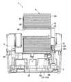
次に、ロールシートホルダ3の概略構成について図8乃至図13に基づいて説明する。
図8乃至図13に示すように、巻芯3Bに巻回されたロールシート3Aが装着されるロールシートホルダ3は、ロールシート3Aの巻芯3Bの筒孔の一端側端縁部に第1筒部35が嵌挿されてロールシート3Aの一方の端面に当接されるガイド部材20と、該巻芯3Bの他端側に第2筒部37が嵌挿されてロールシート3Aの他方の端面に当接される位置決め保持部材12と、このガイド部材20の第1筒部35に嵌挿されて一端側端面の外周部に形成されるフランジ部36が該第1筒部35の外側端面に固着されると共に、他端側端部が位置決め保持部材12の第2筒部37に嵌挿されて該第2筒部37に固着される略筒状のホルダ軸部材40と、から構成されている。従って、ホルダ軸部材40の長さ寸法を変更することにより、異なる幅寸法のロールシート3Aが装着された複数種類のロールシートホルダ3を容易に製作することができる。Next, a schematic configuration of the
As shown in FIGS. 8 to 13, the
また、このガイド部材20は、第1筒部35の外側端面の下側外周部から下側方向に延出されて、ロールシートホルダ収納部4の底面部に形成される位置決め凹部4Aに嵌入されて該位置決め凹部4Aの底面に当接される第1延出部42が形成されている。また、ガイド部材20は、ロールシート3Aの前側方向略1/4円周上の外側端面部を覆うように外側方向に延出される第2延出部43が形成されている。また、この第2延出部43の外周部からロールシート3Aの挿入口18(図6参照)近傍まで上側端縁部が前下がり状に延出される第3延出部44が形成されている。この第3延出部44の先端部の下端面は略水平に形成され、テープ印刷装置1の載置部21上に当接して、該第3延出部44と第2延出部43の内側面によって装着されたロールシート3Aの一側端縁部を挿入口18まで案内するように構成されている。また、この第3延出部44の下端面の載置部21の搬送方向後端縁部に対向する位置から第1延出部42まで所定長さ延出される第4延出部45が形成され、該第3延出部44の下端面が載置部21上に当接された場合には、この第4延出部45の搬送方向先端部分が、装着されたロールシート3Aのシート幅に対向する各第2位置決め溝部22A〜22Dのいずれかに嵌入されるように構成されている(図7参照)。
また、ガイド部材20の第1延出部42の上端部、即ち、第1筒部35の外側端面の外周部の左右両中央部には、正面視略四角形の各切欠部47が設けられ、ホルダ軸部材40のフランジ部36の内側面に突設される各位置決め突起48が嵌入されている。また、ガイド部材20の各延出部43、44、45の内側面には、装着されたロールシート3Aの巻回長さ10m、20m、30mを表す各目盛り43A、43B、43Cが形成されている。尚、ロールシートホルダ3に巻回されるロールシート3Aの最大巻回長さは、約30mの長さである。Further, the
Further, the upper end portion of the first extending
また、ホルダ軸部材40の位置決め保持部材12の第2筒部37内に嵌入される先端部には、該第2筒部37の内側下端部に内側半径方向に突設される位置決めリブ50が嵌入される略縦長の切欠部51が形成されている。これにより、ホルダ軸部材40の切欠部51に位置決め保持部材12の位置決めリブ部50を嵌入することによって、該ホルダ軸部材40を介して位置決め保持部材12とガイド部材20との位置決めを行うことができる。
また、第1筒部35と第2筒部37とによって、ロールシート3Aが巻回された巻芯3Bが回転可能に保持される。尚、ホルダ軸部材40は、巻芯3Bの各長さ寸法に対応して複数種類(第1実施形態では、4種類である。)の長さ寸法のものが設けられている。In addition, a
Further, the
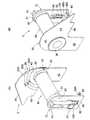
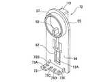
また、位置決め部材12により、第2筒部37の外側端面は閉塞されている。また、該第2筒部37の外周部には、フランジ部55が形成されると共に、このフランジ部55の下側外周部から下側方向に延出される延出部56が形成されている。このフランジ部55と延出部56の内側面がロールシート3A及び巻芯3Bの外側端面に当接される。また、このフランジ部55と延出部56の外側端面部の搬送方向(図10(A)中、左右方向)略中央部に、即ち、ホルダ軸部材40の軸心の端縁部から該軸心に対してほぼ直交するように、上下方向に縦長の断面略矩形状の取付部材13が突設されている。この取付部材13は、正面視下方向に幅狭になるように形成され、テープ印刷装置1のホルダ支持部材15の下方向に幅狭な第1位置決め溝部16内に密着可能に形成されている。また、この取付部材13の突出高さ寸法は、この第1位置決め溝部16の幅寸法にほぼ等しく形成されている。 Further, the outer end surface of the second
また、位置決め部材12の取付部材13の下端部には、該取付部材13の下端部よりも左右方向に各々外側方向に所定長さ(第1実施形態では、約1.5mm〜3mmである。)突出する正面視略四角形の平板状(第1実施形態では、約1.5mm〜3mmの厚さ寸法である。)の案内部57が形成されている。これにより、ロールシートホルダ3を装着する場合は、取付部材13の下端部に形成される案内部57をホルダ支持部材15の外側端面に当接させつつ、取付部材13を第1位置決め溝部16に挿入することによって、該ロールシートホルダ3を容易に位置決めしつつ装着することができる。 In addition, the lower end portion of the
また、位置決め部材12の延出部56の下端縁部は、ガイド部材20の下端縁部よりも所定長さ(第1実施形態では、約1mm〜2.5mmである。)下側方向に突出するように延出されると共に、該下端縁部には、略直角内側方向に所定長さ延出される略長四角形のシート判別部60が形成されている。 Further, the lower end edge of the extending
また、図8(B)及び図13(A)〜(F)に示すように、このシート判別部60には、上述したように、各シート判別センサS1〜S5に対向する所定位置に各センサ孔60A〜60Eが略L字状に配置されて穿設されている。これにより、各センサ孔60A〜60Eは、最大5個穿設されるため、1つひとつの有無を「1」と「0」に対応させることにより、該ロールシートホルダ3に装着されたロールシート3Aの種類を5ビットの符号によって表示することができる。
また、位置決め部材12の取付部材13の下端部には延出部56に縦長四角形の貫通孔62が穿設され、該貫通孔62の上端縁部には、下側方向に先端部に外側方向に突出する突起部が形成された弾性係止片12Aが設けられている。Further, as shown in FIGS. 8B and 13A to 13F, the
In addition, a vertically long rectangular through
次に、上記のように構成されたロールシートホルダ3のテープ印刷装置1への装着について図14に基づいて説明する。
図14(A)に示すように、巻芯3Bに最大幅のロールシート3Aが巻回されたロールシートホルダ3の場合には、先ず、ロールシートホルダ3の位置決め保持部材12の取付部材13をホルダ支持部材15の位置決め溝部16に挿入する。そして、該ロールシートホルダ3のガイド部材20の第3延出部44の下端面を載置部21上に当接させると共に、該ガイド部材20の第4延出部45を載置部21の搬送方向後側角部に形成される第2位置決め溝部21Aに嵌入させる。また、該ガイド部材20の第1延出部42の下端縁部をロールシートホルダ収納部4の底面部に形成される位置決め凹部4A内に嵌入して当接させる。また、同時に、ロールシートホルダ3の位置決め保持部材12の延出部56の下端部に形成されるシート判定部60を、ホルダ支持部材15の基端部内側に形成される判別凹部4Bに挿入すると共に、弾性係止片12Aをホルダ支持部材15の基端部に形成される係合凹部15Aに係合させる。これにより、ロールシートホルダ3がロールシートホルダ収納部4に着脱自在に取り付けられる。また、各シート判別センサS1〜S5を介して対向するシート判別部60の各センサ孔60A〜60Eの有無が検出可能となる。
続いて、レバー27を上方に回動させた状態で、ロールシート3Aの一方の側端縁部をガイド部材20の内側面に当接させつつ、該ロールシート3Aを引きだし、このロールシート3Aの他方の側端縁部を挿入口18の側端縁部に立設された案内リブ部23に当接させつつ挿入口18に挿入する。その後、レバー27を下方に回動させることにより、該ロールシート3Aの先端部がサーマルヘッド31によってプラテンローラ26に押圧され、印字可能な状態になる。Next, attachment of the
As shown in FIG. 14A, in the case of the
Subsequently, in a state where the
また、図13(B)に示すように、巻芯3Bに最小幅のロールシート3Aが巻回されたロールシートホルダ3の場合には、先ず、ロールシートホルダ3の位置決め保持部材12の取付部材13をホルダ支持部材15の位置決め溝部16に挿入する。そして、該ロールシートホルダ3のガイド部材20の第3延出部44の下端面を載置部21上に当接させると共に、該ガイド部材20の第4延出部45を載置部21の搬送方向後側角部に形成される第2位置決め溝部21Dに嵌入させる。そして、該ガイド部材20の第1延出部42の下端縁部をロールシートホルダ収納部4の底面部に形成される位置決め凹部4A内に嵌入して当接させる。また、同時に、ロールシートホルダ3の位置決め保持部材12の延出部56の下端部に形成されるシート判定部60を、ホルダ支持部材15の基端部内側に形成される判別凹部4Bに挿入すると共に、弾性係止片12Aをホルダ支持部材15の基端部に形成される係合凹部15Aに係合させる。これにより、ロールシートホルダ3がロールシートホルダ収納部4に着脱自在に取り付けられる。また、各シート判別センサS1〜S5を介して対向するシート判別部60の各センサ孔60A〜60Eの有無が検出可能となる。
続いて、レバー27を上方に回動させた状態で、ロールシート3Aの一方の側端縁部をガイド部材20の内側面に当接させつつ、該ロールシート3Aを引きだし、このロールシート3Aの他方の側端縁部を挿入口18の側端縁部に立設された案内リブ部23に当接させつつ挿入口18に挿入する。その後、レバー27を下方に回動させることにより、該ロールシート3Aの先端部がサーマルヘッド31によってプラテンローラ26に押圧され、印字可能な状態になる。As shown in FIG. 13B, in the case of the
Subsequently, in a state where the
ここで、プラテンローラ26は、搬送手段として機能する。また、プラテンローラ26及びサーマルヘッド31は、印刷手段を構成する。また、第1延出部42、第2延出部43、第3延出部44、及び第4延出部45は、第1フランジ部を構成する。また、ガイド部材20は、第1筒部材として機能する。また、第2筒部37は、第2筒部材として機能する。また、位置決め保持部材12は、基準側保持部材として機能する。また、フランジ部36は、第2フランジ部として機能する。また、ホルダ軸部材40は、第3筒部材として機能する。また、取付部材13は、位置決めリブ部として機能する。また、シート判別部60は、第2延出部として機能する。各センサ孔60A〜60Eは、ロールシート特定部を構成する。また、ホルダ支持部材15及び係合凹部15Aは、支持機構を構成する。また、ホルダ支持部材15は、位置決め支持部材として機能する。また、判別凹部4Bは、凹部として機能する。 Here, the
以上詳細に説明した通り、第1実施形態に係るテープ印刷装置1では、ホルダ支持部材15のロールシートホルダ3側基端部に、ロールシートホルダ3のシート判別部60に形成された各センサ孔60A〜60Eと協働してロールシート3Aの種類を特定する各シート判別センサS1〜S5が設けられているため、このホルダ支持部材15に形成される第1位置決め溝部16に嵌入される取付部材13を介してシート判別部60の各センサ孔60A〜60Eが確実に位置決めされ、各シート判別センサS1〜S5の検出精度の向上を図ることができる。
また、シート判別部60に対向する底面部に、該シート判別部60が上方から嵌め込まれる判別凹部4Bが形成されているため、該判別凹部4B内にシート判別部60が嵌め込まれて各センサ孔60A〜60Eが固定されるため、各シート判別センサS1〜S5を確実に動作させることが可能となり、各シート判別センサS1〜S5の信頼性の向上を図ることができる。As described above in detail, in the
In addition, since the determination
また、ロールシートホルダ3の位置決め保持部材12の外側端面部に突設される取付部材13をテープ印刷装置1の上方に開口する第1位置決め溝部16に位置合わせして嵌入することによって、該位置決め保持部材12の下端縁部からロールシート3Aの最大外径時の下端部外周面に対向するように所定長さ延出されるシート判別部60に形成された各センサ孔60A〜60Eを介して該ロールシート3Aの種類が特定されるため、該各センサ孔60A〜60Eが形成されるシート判別部60をロールシート3Aの軸心の真下に配置することができ、このロールシート3Aの自重によってシート判別部60を各シート判別センサS1〜S5側方向に位置決めすることが可能となり、該シート判別部60の浮き上がり等を防止することができる。 In addition, the positioning
また、位置決め保持部材12の下端縁部からロールシート3Aの最大外径時の下端部外周面に対向するように所定長さ延出されてシート判別部60が設けられているため、該ロールシート3Aの弾性復元力によってロールシート3Aの巻回が少し緩んだ場合には、最外周面の下端部がシート判別部60に当接して押さえられ、該ロールシート3Aのばらけを確実に防止することができる。
更に、ロールシート3Aの引き出し時に、各センサ孔60A〜60Eが形成されるシート判別部60は、該各センサ孔60A〜60E内に嵌入された各シート判別センサS1〜S5を介して固定されるため、該各センサ孔60A〜60Eが各シート判別センサS1〜S5から離れることを確実に防止することができ、印字品質の向上を図ることができる。Further, the
Further, when the
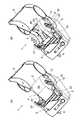
次に、第2実施形態に係るロールシートホルダ及びテープ印刷装置について図15及び図16に基づいて説明する。尚、以下の説明において上記図1乃至図14の第1実施形態に係るロールシートホルダ3及びテープ印刷装置1の構成等と同一符号は、該第1実施形態に係るロールシートホルダ3及びテープ印刷装置1等の構成等と同一あるいは相当部分を示すものである。
第2実施形態に係るロールシートホルダ及びテープ印刷装置の概略構成は、第1実施形態に係るロールシートホルダ3及びテープ印刷装置1とほぼ同じ構成である。また、テープ印刷装置の各種制御処理も第1実施形態に係るテープ印刷装置1とほぼ同じ制御処理である。
但し、第2実施形態に係るロールシートホルダを構成する位置決め保持部材とテープ印刷装置のロールシートホルダ収納部に形成される判別凹部の構成が、第1実施形態に係るロールシートホルダ3を構成する位置決め保持部材12とテープ印刷装置1のロールシートホルダ収納部4に形成される判別凹部4Bの構成と異なっている。Next, a roll sheet holder and a tape printer according to the second embodiment will be described with reference to FIGS. 15 and 16. In the following description, the same reference numerals as those of the
The schematic configuration of the roll sheet holder and the tape printer according to the second embodiment is substantially the same as that of the
However, the positioning holding member constituting the roll sheet holder according to the second embodiment and the configuration of the discrimination recess formed in the roll sheet holder storage portion of the tape printer constitute the
ここで、第2実施形態に係るテープ印刷装置のロールシートホルダ収納部に形成される判別凹部の構成について図15に基づいて説明する。
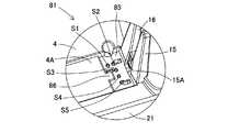
図15に示すように、第2実施形態に係るテープ印刷装置71のロールシートホルダ収納部4の底面部には、ホルダ支持部材15の内側基端部から第2位置決め溝部22Aに対向する位置まで搬送方向に対して略垂直に平面視横長四角形の位置決め凹部4Aが所定深さ(第2実施形態では、約1.5〜3mmの深さである。)で形成されている。この位置決め凹部4Aの搬送方向幅寸法は、ロールシートホルダ3を構成する位置決め保持部材72(図16参照)及びガイド部材20の各下端縁部の幅寸法にほぼ等しくなるように形成されている。また、位置決め凹部4Aのホルダ支持部材15の内側基端部には、位置決め保持部材72の下端縁部から略直角内側方向に延出される後述のシート判別部73(図16参照)に対向する部分が所定深さ(第2実施形態では、約1.5〜3mmの深さである。)深くなるように形成された搬送方向に長い平面視略長四角形の判別凹部75が形成されている。
また、この判別凹部75は、シート判別センサS3とシート判別センサS4との間の略中央部に対向する位置から搬送方向前側の部分が、シート判別センサS1にほぼ対向する位置まで外側方向(図15中、右側方向)に切り欠かれて、位置決め凹部4Aが外側方向に延出されている。Here, the structure of the discrimination | depression recessed part formed in the roll sheet holder accommodating part of the tape printer which concerns on 2nd Embodiment is demonstrated based on FIG.
As shown in FIG. 15, the bottom surface portion of the roll sheet
Further, the determination
また、この判別凹部75には、プッシュ式のマイクロスイッチ等から構成されて、ロールシート3Aの種別を判別するための5個のシート判別センサS1、S2、S3、S4、S5がL字状に設けられている。この各シート判別センサS1〜S5は、プランジャーとマイクロスイッチ等から構成される公知の機械式スイッチからなり、該各プランジャーの上端部は、該判別凹部75の底面部から位置決め凹部4Aの底面部近傍まで突き出るように設けられている。そして、この各シート判別センサS1〜S5に対してシート判別部73の後述の各センサ孔73A〜73E(図16参照)が有るか否かを検出して、そのオン・オフ信号によりロールシートホルダ3に装着されたロールシート3Aの種類を検出するものである。尚、第2実施形態の場合は、各テープ判別センサS1〜S5は、そのプランジャーが常には、判別凹部75の底面から位置決め凹部4Aの底面部近傍まで突き出しており、マイクロスイッチがオフ状態になっている。そして、シート判別部73の各センサ孔73A〜73Eが、各シート判別センサS1〜S5に対向する位置に有る場合には、プランジャーが押下されずマイクロスイッチがオフ状態にあるので、オフ信号が出力され、一方、シート判別部73の各センサ孔73A〜73Eが、各シート判別センサS1〜S5に対向する位置に無い場合には、プランジャーが押下されてマイクロスイッチがオン状態になるので、オン信号が出力される。 In addition, the determination
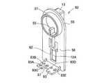
また、図16に示すように、第2実施形態に係るロールシートホルダ3を構成する位置決め保持部材72は、第1実施形態に係る上記位置決め保持部材12とほぼ同じ構成であるが、延出部56の下端縁部には、上記シート判別部60に替えてシート判別部73が形成されている。この位置決め保持部材72のシート判別部73は、延出部56の下端縁部から略直角内側方向に所定長さ延出されると共に、搬送方向後側端縁部が所定長さ内側に突き出している平面視略L字形に形成されている。
また、このシート判別部73は、シート判別部73の搬送方向後側端縁部に、各センサ孔73A、73Bが内側方向一直線上に穿設されると共に、各センサ孔73B〜73Eが搬送方向一直線上に穿設されて、各シート判別センサS1〜S5に対向する所定位置に各センサ孔73A〜73Eが略L字状に配置されて穿設されている。これにより、各センサ孔73A〜73Eは、最大5個穿設されるため、1つひとつの有無を「1」と「0」に対応させることにより、該ロールシートホルダ3に装着されたロールシート3Aの種類を5ビットの符号によって表示することができる。Moreover, as shown in FIG. 16, the
Further, in the
ここで、シート判別部73は、第2延出部として機能する。各センサ孔73A〜73Eは、ロールシート特定部を構成する。また、位置決め保持部材72は、基準側保持部材として機能する。また、判別凹部75は、凹部として機能する。 Here, the
以上詳細に説明した通り、第2実施形態に係るテープ印刷装置71では、上記第1実施形態に係るテープ印刷装置1の作用効果に加えて、更に、位置決め保持部材72のシート判別部73の小型化を図ることができ、ロールシートホルダ3の材料の削減化及び製造コストの低減化を図ることができる。 As described above in detail, in the
次に、第3実施形態に係るロールシートホルダ及びテープ印刷装置について図17及び図18に基づいて説明する。尚、以下の説明において上記図1乃至図14の第1実施形態に係るロールシートホルダ3及びテープ印刷装置1の構成等と同一符号は、該第1実施形態に係るロールシートホルダ3及びテープ印刷装置1等の構成等と同一あるいは相当部分を示すものである。
第3実施形態に係るロールシートホルダ及びテープ印刷装置の概略構成は、第1実施形態に係るロールシートホルダ3及びテープ印刷装置1とほぼ同じ構成である。また、テープ印刷装置の各種制御処理も第1実施形態に係るテープ印刷装置1とほぼ同じ制御処理である。
但し、第3実施形態に係るロールシートホルダを構成する位置決め保持部材とテープ印刷装置のロールシートホルダ収納部に形成される判別凹部の構成が、第1実施形態に係るロールシートホルダ3を構成する位置決め保持部材12とテープ印刷装置1のロールシートホルダ収納部4に形成される判別凹部4Bの構成と異なっている。Next, a roll sheet holder and a tape printer according to the third embodiment will be described with reference to FIGS. In the following description, the same reference numerals as those of the
The schematic configuration of the roll sheet holder and the tape printer according to the third embodiment is substantially the same as that of the
However, the positioning holding member constituting the roll sheet holder according to the third embodiment and the configuration of the discrimination recess formed in the roll sheet holder storage part of the tape printer constitute the
ここで、第3実施形態に係るテープ印刷装置のロールシートホルダ収納部に形成される判別凹部の構成について図17に基づいて説明する。
図17に示すように、第3実施形態に係るテープ印刷装置81のロールシートホルダ収納部4の底面部には、ホルダ支持部材15の内側基端部から第2位置決め溝部22Aに対向する位置まで搬送方向に対して略垂直に平面視横長四角形の位置決め凹部4Aが所定深さ(第3実施形態では、約1.5〜3mmの深さである。)で形成されている。この位置決め凹部4Aの搬送方向幅寸法は、ロールシートホルダ3を構成する位置決め保持部材82(図18参照)及びガイド部材20の各下端縁部の幅寸法にほぼ等しくなるように形成されている。また、位置決め凹部4Aのホルダ支持部材15の内側基端部には、位置決め保持部材82の下端縁部から略直角内側方向に延出される後述のシート判別部83(図18参照)に対向する部分が所定深さ(第3実施形態では、約1.5〜3mmの深さである。)深くなるように形成された搬送方向に長い平面視略長四角形の判別凹部85が形成されている。
また、この判別凹部85は、シート判別センサS3からシート判別センサS4までの間に対向する内側側端縁部の略中央部分が、シート判別センサS1にほぼ対向する位置まで外側方向(図17中、右側方向)に切り欠かれて、位置決め凹部4Aが外側方向に突き出すように延出された位置決め凸部86が形成されている。Here, the structure of the discrimination | depression recessed part formed in the roll sheet holder accommodating part of the tape printer which concerns on 3rd Embodiment is demonstrated based on FIG.
As shown in FIG. 17, the bottom surface portion of the roll sheet
Further, the
また、この判別凹部85には、プッシュ式のマイクロスイッチ等から構成されて、ロールシート3Aの種別を判別するための5個のシート判別センサS1、S2、S3、S4、S5がL字状に設けられている。この各シート判別センサS1〜S5は、プランジャーとマイクロスイッチ等から構成される公知の機械式スイッチからなり、該各プランジャーの上端部は、該判別凹部85の底面部から位置決め凹部4Aの底面部近傍まで突き出るように設けられている。そして、この各シート判別センサS1〜S5に対してシート判別部83の後述の各センサ孔83A〜83E(図18参照)が有るか否かを検出して、そのオン・オフ信号によりロールシートホルダ3に装着されたロールシート3Aの種類を検出するものである。尚、第3実施形態の場合は、各テープ判別センサS1〜S5は、そのプランジャーが常には、判別凹部85の底面から位置決め凹部4Aの底面部近傍まで突き出しており、マイクロスイッチがオフ状態になっている。そして、シート判別部83の各センサ孔83A〜83Eが、各シート判別センサS1〜S5に対向する位置に有る場合には、プランジャーが押下されずマイクロスイッチがオフ状態にあるので、オフ信号が出力され、一方、シート判別部83の各センサ孔83A〜83Eが、各シート判別センサS1〜S5に対向する位置に無い場合には、プランジャーが押下されてマイクロスイッチがオン状態になるので、オン信号が出力される。 In addition, the
また、図18に示すように、第3実施形態に係るロールシートホルダ3を構成する位置決め保持部材82は、第1実施形態に係る上記位置決め保持部材12とほぼ同じ構成であるが、延出部56の下端縁部には、上記シート判別部60に替えてシート判別部83が形成されている。この位置決め保持部材82のシート判別部83は、延出部56の下端縁部から略直角内側方向に所定長さ延出されると共に、センサ孔83Cからセンサ孔83Dまでの間に対向する延出方向外側端縁部の略中央部分が、センサ孔83Aにほぼ対向する位置まで内側方向(図18中、右側方向)に切り欠かれて位置決め凹部87が形成されている。
また、このシート判別部83は、シート判別部83の搬送方向後側端縁部に、各センサ孔83A、83Bが内側方向一直線上に穿設されると共に、各センサ孔83B〜83Eが搬送方向一直線上に穿設され、各シート判別センサS1〜S5に対向する所定位置に各センサ孔83A〜83Eが略L字状に配置されて穿設されている。これにより、各センサ孔83A〜83Eは、最大5個穿設されるため、1つひとつの有無を「1」と「0」に対応させることにより、該ロールシートホルダ3に装着されたロールシート3Aの種類を5ビットの符号によって表示することができる。As shown in FIG. 18, the positioning and holding
Further, in the
ここで、シート判別部83は、第2延出部として機能する。各センサ孔83A〜83Eは、ロールシート特定部を構成する。また、位置決め保持部材82は、基準側保持部材として機能する。また、判別凹部85は、凹部として機能する。 Here, the
以上詳細に説明した通り、第3実施形態に係るテープ印刷装置81では、上記第1実施形態に係るテープ印刷装置1の作用効果に加えて、更に、位置決め保持部材82のシート判別部83に形成される位置決め凹部87を位置決め凹部4Aのホルダ支持部材15側方向に延出される位置決め凸部86に嵌め込むことにより、ロールシートホルダ3の装着時における該位置決め保持部材82の下端部のガタツキを確実に防止でき、印字品質の向上を図ることができる。 As described above in detail, in the
尚、本発明は前記第1実施形態乃至第3実施形態に限定されることはなく、本発明の要旨を逸脱しない範囲内で種々の改良、変形が可能であることは勿論である。 In addition, this invention is not limited to the said 1st Embodiment thru | or 3rd Embodiment, Of course, various improvement and deformation | transformation are possible within the range which does not deviate from the summary of this invention.
例えば、前記第1実施形態乃至第3実施形態に係る各ロールシートホルダ3を構成する各位置決め保持部材12、72、82は、各延出部56の下端縁部に、内側方向に延出されて形成される各シート判別部60、73、83を設け、該各シート判別部60、73、83には、各シート判別センサS1〜S5のプランジャが挿通される各センサ孔60A〜60E、73A〜73E、83A〜83Eを穿設したが、該各シート判別部60、73、83の下面に突起部を設け、各シート判別センサS1〜S5を押下する構成にしてもよい。
ここで、各シート判別センサS1〜S5を押下する構成の一例について図9に基づいて説明する。尚、以下の説明において上記図1乃至図14の第1実施形態に係るロールシートホルダ3及びテープ印刷装置1の構成等と同一符号は、該第1実施形態に係るロールシートホルダ3及びテープ印刷装置1等の構成等と同一あるいは相当部分を示すものである。
図9に示すように、位置決め保持部材91の延出部56の下端縁部から少し上側の位置決め凹部4Aの底面部に対向する部分から、略直角内側方向に所定長さ延出された略長四角形で、上記シート判別部60とほぼ同じ形状のシート判別部92が形成されている。また、このシート判別部92の下面部には、各シート判別センサS1〜S5に対向する位置に各押下ボス92A〜92Eが立設される(図9には、押下ボス92Eのみが立設されている。)。また、この各押下ボス92A〜92Eの下端面は、延出部56の下端面とほぼ同じ高さになるように構成されている。
これにより、シート判別部92の下面部に、各押下ボス92A〜92Eが全部立設された場合は、各シート判別部60、73、83に、各センサ孔60A〜83Eが穿設されていない状態に対応する。また、図9に示すように、シート判別部92の下面部に、押下ボス92Eのみが立設された場合は、各シート判別部60、73、83に、それぞれ4個の各センサ孔60A〜60D、73A〜73D、83A〜83Dが穿設された状態に対応する。また、シート判別部92の下面部に、各押下ボス92A〜92Eが立設されていない場合は、各シート判別部60、73、83に、それぞれ5個の各センサ孔60A〜60E、73A〜73E、83A〜83Eが穿設された状態に対応する。For example, each
Here, an example of a configuration for pressing each of the sheet discrimination sensors S1 to S5 will be described based on FIG. In the following description, the same reference numerals as those of the
As shown in FIG. 9, a substantially length that is extended by a predetermined length in a substantially perpendicular inner direction from a portion facing the bottom surface portion of the
As a result, when all the pressing bosses 92A to 92E are erected on the lower surface of the
1、71、81 テープ印刷装置、 2 本体筐体、 3 ロールシートホルダ
3A ロールシート、 4 ロールシートホルダ収納部、 4A 位置決め凹部
4B、75、85 判別凹部、 5 上カバー
12、72、82、91 位置決め保持部材、 12A 弾性係止片
13 取付部材、 15 ホルダ支持部材、 15A 係合凹部
16 第1位置決め溝部、 18 挿入口、 20 ガイド部材
21 載置部、 22A〜22D 第2位置決め溝部、 23 案内リブ部
26 プラテンローラ、 31 サーマルヘッド、 40 ホルダ軸部材
42 第1延出部、 43 第2延出部、 43A〜43C 目盛り
44 第3延出部、 45 第4延出部、 60、73、83、92 シート判別部
60A〜60E、73A〜73E、83A〜83E センサ孔
92E 押下ボス、 S1〜S5 シート判別センサ
DESCRIPTION OF
Claims (4)
Translated fromJapanese前記巻芯の筒孔の一端側から該筒孔の端縁部に嵌挿されると共に、前記ロールシートの一方の端面に当接される第1フランジ部が外側端面の外周部に形成される第1筒部材と、
前記ロールシートの他方の端面に当接されると共に、内側面に前記巻芯の筒孔の他端側から該筒孔の端縁部に嵌挿される第2筒部材が内側面に立設される基準側保持部材と、
前記第1筒部材に嵌挿されて一端側の外側端面の外周部に前記第1フランジ部の外側面に当接されて固着される第2フランジ部が形成されると共に、他端側が前記第2筒部材に嵌挿されて前記基準保持部材に固着される第3筒部材と、
を備え、
前記第1フランジ部は、前記第1筒部材の外側端面の下側外周面から下側方向に延出されて前記テープ印刷装置の底面部に当接する第1延出部を有し、
前記基準側保持部材は、外側端面部の左右方向略中央部に上下方向縦長に突設される位置決めリブ部と、
下端縁部からロールシートの最大外径時の下端部外周面に対向するように所定長さ延出される第2延出部と、
前記第2延出部に形成されて、前記テープ印刷装置の底面部に配置された貫通孔の有無を検出する複数個のプランジャー式スイッチに対向する所定位置に穿設された複数の貫通孔の有無の組み合わせによって該ロールシートの種類を特定するロールシート特定部と、
を有し、
前記位置決めリブ部は、前記テープ印刷装置の上方に開口する正面視略縦長コの字状の第1位置決め溝部に嵌入されることにより位置決めされて着脱可能に支持されることを特徴とするロールシートホルダ。A state that is used in a tape printing apparatus including a conveying means for conveying a roll sheet wound around a cylindrical winding core and a printing means for printing on the roll sheet, and is detachable in the tape printing apparatus In the roll sheet holder supported by
A first flange portion that is fitted into an end edge portion of the cylindrical hole from one end side of the cylindrical hole of the core and is in contact with one end surface of the roll sheet is formed on the outer peripheral portion of the outer end surface. One cylinder member;
A second cylindrical member that is brought into contact with the other end surface of the roll sheet and that is fitted into the end edge of the cylindrical hole from the other end side of the cylindrical hole of the core is provided on the inner side surface. A reference side holding member
A second flange portion is formed on the outer peripheral portion of the outer end surface on one end side of the first cylindrical member, and is fixed to the outer surface of the first flange portion. A third cylinder member that is fitted into the two cylinder members and fixed to the reference holding member;
With
The first flange portion has a first extending portion that extends downward from a lower outer peripheral surface of the outer end surface of the first cylindrical member and contacts a bottom surface portion of the tape printer,
The reference side holding member includes a positioning rib portion that is vertically long and protrudes at a substantially central portion in the left-right direction of the outer end surface portion,
A second extending portion extending a predetermined length so as to face the outer peripheral surface of the lower end portion at the time of the maximum outer diameter of the roll sheet from the lower end edge portion;
Is formed on the second extendingportion, wherein theplurality of through-holes formed in a predetermined position facing the plurality of plunger-type switch for detecting the presence or absence of the deployedthrough hole on the bottom surface of the tapeprinting apparatusA roll sheet specifying unit for specifying the type of the roll sheetby a combination of presence or absence ,
Have
The roll sheet is characterized in that the positioning rib portion is positioned and fitted in a detachable manner by being fitted into a first positioning groove portion that is substantially U-shaped in front view and opens above the tape printer. holder.
前記ロールシートホルダは、請求項1又は請求項2に記載のロールシートホルダであり、
前記支持機構は、底面部の一側側端縁部に立設されて前記第1位置決め溝部が形成される位置決め支持部材を有し、
前記複数個のプランジャー式スイッチは、前記位置決め支持部材のロールシートホルダ側基端部に設けられていることを特徴とするテープ印刷装置。In a state in which a conveying means for conveying a roll sheet wound around a cylindrical core, a printing means for printing on the roll sheet, and a roll sheet holder around which the roll sheet is wound are detachable A tape printing apparatus comprising: a support mechanism for supporting;
The roll sheet holder is the roll sheet holder according to claim 1or claim2 ,
The support mechanism has a positioning support member that is erected on one side end edge of the bottom surface portion to form the first positioning groove portion,
The tape printing apparatus, wherein theplurality of plunger switches are provided at a base end portion of the positioning support member on a roll sheet holder side.
前記複数個のプランジャー式スイッチは、前記凹部に配置されていることを特徴とする請求項3に記載のテープ印刷装置。The formed on the bottom surface facing the second extending portionhave a recess second extending portion is fitted fromabove,
It said plurality is of plunger type switch, the tape printing apparatus according to claim3, characterized thatthey are being placed in the recess.
Priority Applications (10)
| Application Number | Priority Date | Filing Date | Title |
|---|---|---|---|
| JP2004001036AJP4333367B2 (en) | 2004-01-06 | 2004-01-06 | Roll sheet holder and tape printer |
| US10/974,671US7070348B2 (en) | 2004-01-06 | 2004-10-28 | Roll sheet holder and tape printer |
| AT04028330TATE342807T1 (en) | 2004-01-06 | 2004-11-30 | TAPE ROLL HOLDER AND TAPE PRINTING DEVICE |
| EP04028330AEP1552949B1 (en) | 2004-01-06 | 2004-11-30 | Roll sheet holder and tape printer |
| EP06017570.0AEP1719630B1 (en) | 2004-01-06 | 2004-11-30 | Roll sheet holder and tape printer |
| DE602004002844TDE602004002844T2 (en) | 2004-01-06 | 2004-11-30 | Tape roll holder and tape printer |
| CNB2004100615676ACN100408344C (en) | 2004-01-06 | 2004-12-28 | Roll paper holder and tape printer |
| CN200810125063.4ACN101310989B (en) | 2004-01-06 | 2004-12-28 | Web Holders and Tape Printers |
| US11/439,182US7232268B2 (en) | 2004-01-06 | 2006-05-24 | Roll sheet holder and tape printer |
| US11/797,468US7404684B2 (en) | 2004-01-06 | 2007-05-03 | Roll sheet holder and tape printer |
Applications Claiming Priority (1)
| Application Number | Priority Date | Filing Date | Title |
|---|---|---|---|
| JP2004001036AJP4333367B2 (en) | 2004-01-06 | 2004-01-06 | Roll sheet holder and tape printer |
Publications (2)
| Publication Number | Publication Date |
|---|---|
| JP2005193468A JP2005193468A (en) | 2005-07-21 |
| JP4333367B2true JP4333367B2 (en) | 2009-09-16 |
Family
ID=34587666
Family Applications (1)
| Application Number | Title | Priority Date | Filing Date |
|---|---|---|---|
| JP2004001036AExpired - Fee RelatedJP4333367B2 (en) | 2004-01-06 | 2004-01-06 | Roll sheet holder and tape printer |
Country Status (6)
| Country | Link |
|---|---|
| US (3) | US7070348B2 (en) |
| EP (2) | EP1719630B1 (en) |
| JP (1) | JP4333367B2 (en) |
| CN (2) | CN101310989B (en) |
| AT (1) | ATE342807T1 (en) |
| DE (1) | DE602004002844T2 (en) |
Families Citing this family (44)
| Publication number | Priority date | Publication date | Assignee | Title |
|---|---|---|---|---|
| JP4333367B2 (en)* | 2004-01-06 | 2009-09-16 | ブラザー工業株式会社 | Roll sheet holder and tape printer |
| JP4492125B2 (en)* | 2004-01-06 | 2010-06-30 | ブラザー工業株式会社 | Roll sheet holder and tape printer |
| US7907290B2 (en)* | 2005-12-23 | 2011-03-15 | Eastman Kodak Company | Printer with variable lead advance |
| JP4725567B2 (en)* | 2007-09-28 | 2011-07-13 | ブラザー工業株式会社 | Roll sheet holder |
| JP2010046977A (en)* | 2008-08-25 | 2010-03-04 | Seiko Instruments Inc | Thermal printer |
| EP2965916B1 (en) | 2008-12-25 | 2021-03-03 | Brother Kogyo Kabushiki Kaisha | Tape cassette and tape printer |
| CN201989420U (en)* | 2008-12-25 | 2011-09-28 | 兄弟工业株式会社 | Tape cassette and tape printer |
| EP2370264B1 (en) | 2008-12-25 | 2014-08-27 | Brother Kogyo Kabushiki Kaisha | Tape cassette and tape printer |
| US12296580B2 (en) | 2009-03-31 | 2025-05-13 | Brother Kogyo Kabushiki Kaisha | Tape cassette |
| RU2533666C2 (en) | 2009-03-31 | 2014-11-20 | Бразер Когио Кабусики Кайся | Cassette with tape and tape printer |
| WO2010113782A1 (en) | 2009-03-31 | 2010-10-07 | ブラザー工業株式会社 | Tape cassette |
| CN102361760B (en) | 2009-03-31 | 2015-04-01 | 兄弟工业株式会社 | with box |
| PL2414165T3 (en)* | 2009-03-31 | 2014-08-29 | Brother Ind Ltd | Tape cassette and tape printer |
| JP4947085B2 (en)* | 2009-03-31 | 2012-06-06 | ブラザー工業株式会社 | Tape cassette |
| JP5136503B2 (en)* | 2009-03-31 | 2013-02-06 | ブラザー工業株式会社 | Tape cassette |
| EP4067095B1 (en) | 2009-03-31 | 2025-08-20 | Brother Kogyo Kabushiki Kaisha | Tape cassette |
| WO2011001487A1 (en) | 2009-06-30 | 2011-01-06 | Brother Kogyo Kabushiki Kaisha | Tape cassette and tape printer |
| US20100329767A1 (en)* | 2009-06-30 | 2010-12-30 | Brother Kogyo Kabushiki Kaisha | Tape cassette |
| JP5326950B2 (en)* | 2009-09-09 | 2013-10-30 | ブラザー工業株式会社 | Tape cassette |
| JP5299782B2 (en)* | 2009-09-30 | 2013-09-25 | ブラザー工業株式会社 | Label making device |
| JP2011110812A (en)* | 2009-11-27 | 2011-06-09 | Seiko Epson Corp | Recording device and recording medium supplying structure for the recording device |
| EP2514600B1 (en) | 2009-12-16 | 2015-01-21 | Brother Kogyo Kabushiki Kaisha | Tape cassette |
| CN102481794B (en) | 2009-12-28 | 2014-12-10 | 兄弟工业株式会社 | with box |
| JP5496648B2 (en)* | 2009-12-28 | 2014-05-21 | サトーホールディングス株式会社 | Positioning device for printing member in printer |
| USD654949S1 (en)* | 2010-04-12 | 2012-02-28 | Zih Corp. | Printer |
| USD681719S1 (en)* | 2011-06-02 | 2013-05-07 | Able Systems Limited | Printer |
| JP5920660B2 (en)* | 2012-05-11 | 2016-05-18 | 株式会社リコー | Rolled medium holding mechanism, paper feeding device, image forming apparatus |
| USD713871S1 (en) | 2012-12-19 | 2014-09-23 | Zih Corp. | Printer |
| USD736830S1 (en) | 2013-01-18 | 2015-08-18 | Zih Corp. | Animated operation indication icon for a printer display, display screen, computer display, electronic display, or the like |
| US8870113B2 (en)* | 2013-03-25 | 2014-10-28 | Tsc Auto Id Technology Co., Ltd. | Dual-direction positioning device |
| USD750703S1 (en) | 2013-10-18 | 2016-03-01 | Zih Corp. | Printer housing |
| JP6460761B2 (en)* | 2014-12-03 | 2019-01-30 | サトーホールディングス株式会社 | Printer |
| USD798379S1 (en) | 2015-02-16 | 2017-09-26 | Zih Corp. | Printer |
| CN106427247A (en)* | 2016-10-27 | 2017-02-22 | 顺丰科技有限公司 | Printing machine, suite, system and method |
| CN106393981B (en)* | 2016-11-23 | 2018-05-25 | 浙江维融电子科技股份有限公司 | A kind of code-spraying mechanism |
| US11840413B2 (en)* | 2017-03-17 | 2023-12-12 | Sato Holdings Kabushiki Kaisha | Roll printer holder |
| JP1584452S (en)* | 2017-03-28 | 2020-08-24 | ||
| CN106865309A (en)* | 2017-04-13 | 2017-06-20 | 苏州市嘉明机械制造有限公司 | For the discharge mechanism of wiring board superposing machine |
| CN107650517A (en)* | 2017-10-23 | 2018-02-02 | 天津广大纸业股份有限公司 | A kind of POS label papers printer |
| USD893591S1 (en)* | 2018-12-18 | 2020-08-18 | Zebra Technologies Corporation | Media processing device |
| JP7433966B2 (en)* | 2020-02-14 | 2024-02-20 | 東芝テック株式会社 | printer device |
| US12124991B2 (en) | 2020-03-19 | 2024-10-22 | Trackonomy Systems, Inc. | Handheld tape node dispenser and method |
| CN112497936B (en)* | 2020-12-04 | 2022-09-16 | 厦门汉印电子技术有限公司 | Paper width detecting assembly and printer with same |
| JP2023131726A (en)* | 2022-03-09 | 2023-09-22 | セイコーエプソン株式会社 | cartridge |
Family Cites Families (23)
| Publication number | Priority date | Publication date | Assignee | Title |
|---|---|---|---|---|
| JPH0319047U (en) | 1989-03-23 | 1991-02-25 | ||
| JP2726309B2 (en) | 1989-06-16 | 1998-03-11 | 株式会社日立製作所 | Memory control method and device |
| EP0648609B1 (en)* | 1993-10-15 | 2001-01-03 | Monarch Marking Systems, Inc. | Printer and methods |
| JP3536842B2 (en)* | 1996-03-06 | 2004-06-14 | セイコーエプソン株式会社 | Printer |
| US5884860A (en)* | 1996-03-19 | 1999-03-23 | Ricoh Company, Ltd. | Rolled paper feeding apparatus which provides a constant torque for uncurling paper and a torque limiting device therefor |
| DE69705353T2 (en)* | 1996-04-29 | 2002-04-25 | Hewlett-Packard Co.(A Delaware Corporation), Palo Alto | Adjustable spindle drive arrangement for media conveyance by means of rollers in an ink jet printer / plotter |
| JP3721745B2 (en)* | 1997-10-17 | 2005-11-30 | ブラザー工業株式会社 | Recording device |
| US6261013B1 (en)* | 1999-04-01 | 2001-07-17 | Eltron International, Inc. | Door mounted roll support |
| JP2000313549A (en)* | 1999-04-30 | 2000-11-14 | Copyer Co Ltd | Roll-like recording medium holding device |
| US6241407B1 (en)* | 1999-09-16 | 2001-06-05 | Monarch Marking Systems, Inc. | Portable printer |
| US6158342A (en)* | 1999-09-27 | 2000-12-12 | Axiohm Transaction Solutions, Inc. | Paper supply adjustment mechanism |
| US6431492B1 (en)* | 1999-10-27 | 2002-08-13 | Zih Corp. | Integrated adjustable core support and medium guide device |
| US6302604B1 (en)* | 2000-01-05 | 2001-10-16 | Zih Corp. | Rack and pinion medium roll support |
| US6565273B2 (en)* | 2000-04-19 | 2003-05-20 | Seiko Epson Corporation | Printer that accomodates rolled paper having various widths |
| JP2002096515A (en) | 2000-09-21 | 2002-04-02 | Brother Ind Ltd | Roll cassette and tape printer |
| US6609844B1 (en)* | 2001-11-09 | 2003-08-26 | Zih Corp. | Portable printer having automatic print alignment |
| US6786660B1 (en)* | 2002-02-19 | 2004-09-07 | Sony Chemicals Corporation Of America | Detectable spool and associated hub |
| KR100415398B1 (en)* | 2002-03-08 | 2004-01-16 | 코리아프린팅시스템 주식회사 | Holding apparatus of paper for label printer |
| JP2004262588A (en)* | 2003-02-28 | 2004-09-24 | Seiko Epson Corp | Roll paper mounting device and printer using the same |
| US7011464B2 (en)* | 2003-03-06 | 2006-03-14 | Toshiba Tec Kabushiki Kaisha | Apparatus for detecting an end portion of a recording medium |
| JP4492125B2 (en)* | 2004-01-06 | 2010-06-30 | ブラザー工業株式会社 | Roll sheet holder and tape printer |
| JP4333367B2 (en)* | 2004-01-06 | 2009-09-16 | ブラザー工業株式会社 | Roll sheet holder and tape printer |
| US6874958B1 (en)* | 2004-02-20 | 2005-04-05 | Zih Corp. | Portable printer with spindle members for rotationally mounting media rolls of different core diameters |
- 2004
- 2004-01-06JPJP2004001036Apatent/JP4333367B2/ennot_activeExpired - Fee Related
- 2004-10-28USUS10/974,671patent/US7070348B2/ennot_activeExpired - Lifetime
- 2004-11-30ATAT04028330Tpatent/ATE342807T1/ennot_activeIP Right Cessation
- 2004-11-30DEDE602004002844Tpatent/DE602004002844T2/ennot_activeExpired - Lifetime
- 2004-11-30EPEP06017570.0Apatent/EP1719630B1/ennot_activeExpired - Lifetime
- 2004-11-30EPEP04028330Apatent/EP1552949B1/ennot_activeExpired - Lifetime
- 2004-12-28CNCN200810125063.4Apatent/CN101310989B/ennot_activeExpired - Fee Related
- 2004-12-28CNCNB2004100615676Apatent/CN100408344C/ennot_activeExpired - Fee Related
- 2006
- 2006-05-24USUS11/439,182patent/US7232268B2/ennot_activeExpired - Lifetime
- 2007
- 2007-05-03USUS11/797,468patent/US7404684B2/ennot_activeExpired - Lifetime
Also Published As
| Publication number | Publication date |
|---|---|
| DE602004002844D1 (en) | 2006-11-30 |
| CN100408344C (en) | 2008-08-06 |
| CN101310989B (en) | 2010-06-02 |
| US7404684B2 (en) | 2008-07-29 |
| EP1552949A1 (en) | 2005-07-13 |
| US7232268B2 (en) | 2007-06-19 |
| DE602004002844T2 (en) | 2007-05-16 |
| US7070348B2 (en) | 2006-07-04 |
| US20050147450A1 (en) | 2005-07-07 |
| US20070212150A1 (en) | 2007-09-13 |
| EP1719630B1 (en) | 2013-07-24 |
| EP1552949B1 (en) | 2006-10-18 |
| CN101310989A (en) | 2008-11-26 |
| CN1636755A (en) | 2005-07-13 |
| ATE342807T1 (en) | 2006-11-15 |
| EP1719630A1 (en) | 2006-11-08 |
| US20060210343A1 (en) | 2006-09-21 |
| JP2005193468A (en) | 2005-07-21 |
Similar Documents
| Publication | Publication Date | Title |
|---|---|---|
| JP4333367B2 (en) | Roll sheet holder and tape printer | |
| JP4492125B2 (en) | Roll sheet holder and tape printer | |
| JP4924267B2 (en) | Tape printer | |
| EP1552944B1 (en) | Label printer and printing medium | |
| EP1614546B1 (en) | Printer | |
| JP4582135B2 (en) | Roll sheet holder | |
| JP4725566B2 (en) | Roll sheet holder | |
| JP4725567B2 (en) | Roll sheet holder | |
| JP2005266180A (en) | Tape for tape printer | |
| JP4613490B2 (en) | Roll sheet holder | |
| JP4923895B2 (en) | Tape printer | |
| JP2007301910A (en) | Printing device | |
| JP2005193470A (en) | Label printer | |
| JP4639671B2 (en) | Rolled print medium holding member | |
| JP2005280226A (en) | Label printer |
Legal Events
| Date | Code | Title | Description |
|---|---|---|---|
| A621 | Written request for application examination | Free format text:JAPANESE INTERMEDIATE CODE: A621 Effective date:20060928 | |
| A977 | Report on retrieval | Free format text:JAPANESE INTERMEDIATE CODE: A971007 Effective date:20081208 | |
| A131 | Notification of reasons for refusal | Free format text:JAPANESE INTERMEDIATE CODE: A131 Effective date:20081216 | |
| A521 | Request for written amendment filed | Free format text:JAPANESE INTERMEDIATE CODE: A523 Effective date:20090129 | |
| TRDD | Decision of grant or rejection written | ||
| A01 | Written decision to grant a patent or to grant a registration (utility model) | Free format text:JAPANESE INTERMEDIATE CODE: A01 Effective date:20090602 | |
| A01 | Written decision to grant a patent or to grant a registration (utility model) | Free format text:JAPANESE INTERMEDIATE CODE: A01 | |
| A61 | First payment of annual fees (during grant procedure) | Free format text:JAPANESE INTERMEDIATE CODE: A61 Effective date:20090615 | |
| FPAY | Renewal fee payment (event date is renewal date of database) | Free format text:PAYMENT UNTIL: 20120703 Year of fee payment:3 | |
| R150 | Certificate of patent or registration of utility model | Ref document number:4333367 Country of ref document:JP Free format text:JAPANESE INTERMEDIATE CODE: R150 Free format text:JAPANESE INTERMEDIATE CODE: R150 | |
| FPAY | Renewal fee payment (event date is renewal date of database) | Free format text:PAYMENT UNTIL: 20120703 Year of fee payment:3 | |
| FPAY | Renewal fee payment (event date is renewal date of database) | Free format text:PAYMENT UNTIL: 20130703 Year of fee payment:4 | |
| LAPS | Cancellation because of no payment of annual fees |