JP4332699B2 - Continuously variable transmission - Google Patents
Continuously variable transmissionDownload PDFInfo
- Publication number
- JP4332699B2 JP4332699B2JP2002585835AJP2002585835AJP4332699B2JP 4332699 B2JP4332699 B2JP 4332699B2JP 2002585835 AJP2002585835 AJP 2002585835AJP 2002585835 AJP2002585835 AJP 2002585835AJP 4332699 B2JP4332699 B2JP 4332699B2
- Authority
- JP
- Japan
- Prior art keywords
- transmission
- disk
- speed regulator
- drive disk
- longitudinal axis
- Prior art date
- Legal status (The legal status is an assumption and is not a legal conclusion. Google has not performed a legal analysis and makes no representation as to the accuracy of the status listed.)
- Expired - Fee Related
Links
- 230000005540biological transmissionEffects0.000titleclaimsabstractdescription217
- 230000002093peripheral effectEffects0.000claimsdescription34
- 230000033001locomotionEffects0.000claimsdescription16
- 125000006850spacer groupChemical group0.000claimsdescription16
- 230000008859changeEffects0.000claimsdescription4
- 230000000670limiting effectEffects0.000claimsdescription3
- 230000008878couplingEffects0.000claimsdescription2
- 238000010168coupling processMethods0.000claimsdescription2
- 238000005859coupling reactionMethods0.000claimsdescription2
- 238000003780insertionMethods0.000claims1
- 230000037431insertionEffects0.000claims1
- 230000006872improvementEffects0.000abstractdescription12
- 238000000034methodMethods0.000abstractdescription11
- 239000004753textileSubstances0.000abstract1
- UQMRAFJOBWOFNS-UHFFFAOYSA-Nbutyl 2-(2,4-dichlorophenoxy)acetateChemical compoundCCCCOC(=O)COC1=CC=C(Cl)C=C1ClUQMRAFJOBWOFNS-UHFFFAOYSA-N0.000description16
- 230000007246mechanismEffects0.000description15
- 230000006835compressionEffects0.000description8
- 238000007906compressionMethods0.000description8
- 238000005096rolling processMethods0.000description7
- 230000002829reductive effectEffects0.000description4
- 230000004323axial lengthEffects0.000description3
- 230000008901benefitEffects0.000description3
- 230000009471actionEffects0.000description2
- 238000010586diagramMethods0.000description2
- 230000007935neutral effectEffects0.000description2
- 239000007787solidSubstances0.000description2
- 230000007423decreaseEffects0.000description1
- 230000003247decreasing effectEffects0.000description1
- 239000000428dustSubstances0.000description1
- 239000013013elastic materialSubstances0.000description1
- 230000036961partial effectEffects0.000description1
- 230000000149penetrating effectEffects0.000description1
- 230000008569processEffects0.000description1
- 230000002441reversible effectEffects0.000description1
- 238000000926separation methodMethods0.000description1
- 230000007704transitionEffects0.000description1
Images


Classifications
- F—MECHANICAL ENGINEERING; LIGHTING; HEATING; WEAPONS; BLASTING
- F16—ENGINEERING ELEMENTS AND UNITS; GENERAL MEASURES FOR PRODUCING AND MAINTAINING EFFECTIVE FUNCTIONING OF MACHINES OR INSTALLATIONS; THERMAL INSULATION IN GENERAL
- F16H—GEARING
- F16H15/00—Gearings for conveying rotary motion with variable gear ratio, or for reversing rotary motion, by friction between rotary members
- F16H15/02—Gearings for conveying rotary motion with variable gear ratio, or for reversing rotary motion, by friction between rotary members without members having orbital motion
- F16H15/04—Gearings providing a continuous range of gear ratios
- F—MECHANICAL ENGINEERING; LIGHTING; HEATING; WEAPONS; BLASTING
- F16—ENGINEERING ELEMENTS AND UNITS; GENERAL MEASURES FOR PRODUCING AND MAINTAINING EFFECTIVE FUNCTIONING OF MACHINES OR INSTALLATIONS; THERMAL INSULATION IN GENERAL
- F16H—GEARING
- F16H15/00—Gearings for conveying rotary motion with variable gear ratio, or for reversing rotary motion, by friction between rotary members
- F16H15/48—Gearings for conveying rotary motion with variable gear ratio, or for reversing rotary motion, by friction between rotary members with members having orbital motion
- F16H15/50—Gearings providing a continuous range of gear ratios
- F16H15/52—Gearings providing a continuous range of gear ratios in which a member of uniform effective diameter mounted on a shaft may co-operate with different parts of another member
- B—PERFORMING OPERATIONS; TRANSPORTING
- B62—LAND VEHICLES FOR TRAVELLING OTHERWISE THAN ON RAILS
- B62M—RIDER PROPULSION OF WHEELED VEHICLES OR SLEDGES; POWERED PROPULSION OF SLEDGES OR SINGLE-TRACK CYCLES; TRANSMISSIONS SPECIALLY ADAPTED FOR SUCH VEHICLES
- B62M11/00—Transmissions characterised by the use of interengaging toothed wheels or frictionally-engaging wheels
- B62M11/04—Transmissions characterised by the use of interengaging toothed wheels or frictionally-engaging wheels of changeable ratio
- B62M11/12—Transmissions characterised by the use of interengaging toothed wheels or frictionally-engaging wheels of changeable ratio with frictionally-engaging wheels
- F—MECHANICAL ENGINEERING; LIGHTING; HEATING; WEAPONS; BLASTING
- F16—ENGINEERING ELEMENTS AND UNITS; GENERAL MEASURES FOR PRODUCING AND MAINTAINING EFFECTIVE FUNCTIONING OF MACHINES OR INSTALLATIONS; THERMAL INSULATION IN GENERAL
- F16H—GEARING
- F16H15/00—Gearings for conveying rotary motion with variable gear ratio, or for reversing rotary motion, by friction between rotary members
- F16H15/02—Gearings for conveying rotary motion with variable gear ratio, or for reversing rotary motion, by friction between rotary members without members having orbital motion
- F16H15/04—Gearings providing a continuous range of gear ratios
- F16H15/06—Gearings providing a continuous range of gear ratios in which a member A of uniform effective diameter mounted on a shaft may co-operate with different parts of a member B
- F16H15/26—Gearings providing a continuous range of gear ratios in which a member A of uniform effective diameter mounted on a shaft may co-operate with different parts of a member B in which the member B has a spherical friction surface centered on its axis of revolution
- F16H15/28—Gearings providing a continuous range of gear ratios in which a member A of uniform effective diameter mounted on a shaft may co-operate with different parts of a member B in which the member B has a spherical friction surface centered on its axis of revolution with external friction surface
- F—MECHANICAL ENGINEERING; LIGHTING; HEATING; WEAPONS; BLASTING
- F16—ENGINEERING ELEMENTS AND UNITS; GENERAL MEASURES FOR PRODUCING AND MAINTAINING EFFECTIVE FUNCTIONING OF MACHINES OR INSTALLATIONS; THERMAL INSULATION IN GENERAL
- F16H—GEARING
- F16H61/00—Control functions within control units of change-speed- or reversing-gearings for conveying rotary motion ; Control of exclusively fluid gearing, friction gearing, gearings with endless flexible members or other particular types of gearing
- F16H61/66—Control functions within control units of change-speed- or reversing-gearings for conveying rotary motion ; Control of exclusively fluid gearing, friction gearing, gearings with endless flexible members or other particular types of gearing specially adapted for continuously variable gearings
- F16H61/664—Friction gearings
- F16H61/6649—Friction gearings characterised by the means for controlling the torque transmitting capability of the gearing
- F—MECHANICAL ENGINEERING; LIGHTING; HEATING; WEAPONS; BLASTING
- F16—ENGINEERING ELEMENTS AND UNITS; GENERAL MEASURES FOR PRODUCING AND MAINTAINING EFFECTIVE FUNCTIONING OF MACHINES OR INSTALLATIONS; THERMAL INSULATION IN GENERAL
- F16H—GEARING
- F16H63/00—Control outputs from the control unit to change-speed- or reversing-gearings for conveying rotary motion or to other devices than the final output mechanism
- F16H63/02—Final output mechanisms therefor; Actuating means for the final output mechanisms
- F16H63/04—Final output mechanisms therefor; Actuating means for the final output mechanisms a single final output mechanism being moved by a single final actuating mechanism
- F16H63/06—Final output mechanisms therefor; Actuating means for the final output mechanisms a single final output mechanism being moved by a single final actuating mechanism the final output mechanism having an indefinite number of positions
- F16H63/067—Final output mechanisms therefor; Actuating means for the final output mechanisms a single final output mechanism being moved by a single final actuating mechanism the final output mechanism having an indefinite number of positions mechanical actuating means
Landscapes
- Engineering & Computer Science (AREA)
- General Engineering & Computer Science (AREA)
- Mechanical Engineering (AREA)
- Chemical & Material Sciences (AREA)
- Combustion & Propulsion (AREA)
- Transportation (AREA)
- Friction Gearing (AREA)
- General Details Of Gearings (AREA)
- Valve Device For Special Equipments (AREA)
- Valve-Gear Or Valve Arrangements (AREA)
- Electrical Discharge Machining, Electrochemical Machining, And Combined Machining (AREA)
- Retarders (AREA)
Abstract
Description
Translated fromJapanese発明の背景
発明の分野
本発明の分野は、概ね変速機に関し、特には、本発明は、無段変速機に関する。Background of the Invention
The field of the invention relates generally to transmissions, and in particular, the invention relates to continuously variable transmissions.
関連技術の説明
本発明は、無段変速機の分野に関し、開発されてきた、先行技術における改良であるいくつかの新規な特徴及び発明の態様を含む。無段変速機を提供するために、トルク入力ディスクとトルク出力ディスクとの間のハウジング内において支持されたトラクションローラーから力を伝達する種々のトラクションローラー式変速機が、開発されてきた。そのような変速装置では、トラクションローラーは、支持構造体に装着されて、この支持構造体は、旋回すると、所望の変速比により直径が変わる円を描く、トラクションローラーとトルクディスクとの係合を引き起こす。Description of Related Art The present invention relates to the field of continuously variable transmissions and includes several novel features and aspects of the invention that have been developed and are improvements over the prior art. In order to provide a continuously variable transmission, various traction roller transmissions have been developed that transmit force from a traction roller supported in a housing between a torque input disk and a torque output disk. In such a transmission, the traction roller is mounted on a support structure that, when swiveled, draws a circle whose diameter changes with the desired gear ratio, engaging the traction roller with the torque disk. cause.
しかしながら、これらの従来の解決方法の成功は、制限されている。例えば、1つの解決法では、可変で調整可能な変速比を有する乗り物用駆動ハブが開示される。この方法は、各ローラーの回転軸線を傾けるために、トラクションローラーの各側に一枚ずつ、2枚の虹彩型プレートを使用することを教示する。しかしながら、虹彩型プレートの使用は、変速シフト中に虹彩型プレートを調節するために多くの部品が必要となることから非常に複雑になる可能性がある。この変速機に伴う別の問題点は、各ローラーに対して殆ど静止するように形成されるガイドリングを有することである。ガイドリングが静止しているので、各トラクションローラーの回転軸線をシフトさせることは困難である。 However, the success of these conventional solutions is limited. For example, in one solution, a vehicle drive hub having a variable and adjustable transmission ratio is disclosed. This method teaches the use of two iris plates, one on each side of the traction roller, to tilt the axis of rotation of each roller. However, the use of an iris plate can be very complicated because many parts are required to adjust the iris plate during a shift shift. Another problem with this transmission is having a guide ring that is configured to be almost stationary with respect to each roller. Since the guide ring is stationary, it is difficult to shift the rotation axis of each traction roller.
先のこの設計に対する1つの改良には、駆動部材および従動部材が回転する軸が含まれる。駆動部材および従動部材は、軸に装着されるとともに、軸周りに等距離にかつ径方向に配置された複数の動力調整器と接触する。動力調整器は、両部材と摩擦接触し、駆動部材から従動部材に動力を伝達する。軸に同心にかつ動力調整器同士の間に配置された支持部材が、駆動部材と従動部材とを摩擦接触させるために、動力調整器同士を離しておくように力をかける。この設計の限界は、変速機へのトルク負荷が変化する時に、駆動部材と従動軸部材とを動力調整器に十分に摩擦接触させておくために適切な軸方向力を生成する手段がないことである。この設計のさらなる限界は、高トルクでかつ非常に低速度という状態にするシフトが難しいこと、並びに変速機の係合を解除し惰性回転させる手段が不十分であることである。 One improvement to this previous design includes an axis around which the drive member and follower member rotate. The driving member and the driven member are attached to the shaft and contact with a plurality of power regulators arranged at equal distances around the shaft and in the radial direction. The power adjuster is in frictional contact with both members and transmits power from the drive member to the driven member. A support member disposed concentrically with the shaft and between the power regulators exerts a force to keep the power regulators separated from each other in order to frictionally contact the drive member and the driven member. The limitation of this design is that there is no means to generate an appropriate axial force to keep the drive member and driven shaft member in sufficient frictional contact with the power regulator when the torque load on the transmission changes. It is. A further limitation of this design is that it is difficult to shift to a high torque and very low speed, and that there is insufficient means to disengage the transmission and cause inertial rotation.
したがって、改良された動力調整器支持物およびシフト機構、種々のトルクおよび動力負荷用の駆動および従動部材に適切な軸方向スラストをかける手段、並びに惰性回転用クラッチを係合解除し再係合する手段を有する無段変速装置に対する要請がある。 Thus, an improved power regulator support and shift mechanism, means for applying appropriate axial thrust to the drive and driven members for various torques and power loads, and the inertial clutch for disengaging and re-engaging. There is a need for a continuously variable transmission having means.
発明の概要
本システムおよび方法は、いくつかの特徴を有し、それらの1つのみが、単独で望ましい特性をもたらすわけではない。以下の特許請求の範囲により表わされる範囲を限定せずに、ここで、さらに顕著な特徴を簡潔に説明する。この説明を考慮し特に「好ましい実施形態の詳細な説明」と題する項を読んだ後には、本システムおよび方法の特徴が、従来のシステムおよび方法に対するいくつかの利点をいかに提供するかを理解されよう。SUMMARY OF THEINVENTION The present system and method have several features, not one of which alone provides desirable properties. Without limiting the scope expressed by the following claims, the more prominent features will now be described briefly. In view of this description, and particularly after reading the section entitled “Detailed Description of the Preferred Embodiments”, it will be understood how the features of the present system and method provide several advantages over conventional systems and methods. Like.
一態様では、長手方向軸線および複数の速度調整器を有する無段変速機が、開示される。各速度調整器は、傾斜可能な回転軸線を有し、長手方向軸線から径方向外側に配置される。さらに、長手方向軸線周りを環状に回転可能でありさらに各速度調整器の第1の部分と接触する駆動ディスクと、長手方向軸線周りを環状に回転可能な支持部材とが提供される。同様に長手方向軸線周りを環状に回転可能な軸受ディスクと少なくとも2つの軸方向力ジェネレーターとが、提供される。軸方向力ジェネレーターは、駆動ディスクと軸受ディスクとの間に配置され、各軸方向力ジェネレーターは、駆動ディスクに軸方向力をかけるように形成される。 In one aspect, a continuously variable transmission having a longitudinal axis and a plurality of speed regulators is disclosed. Each speed regulator has a tiltable axis of rotation and is arranged radially outward from the longitudinal axis. In addition, there is provided a drive disk that is annularly rotatable about the longitudinal axis and in contact with the first portion of each speed regulator, and a support member that is annularly rotatable about the longitudinal axis. Similarly, a bearing disk and at least two axial force generators are provided that are annularly rotatable about the longitudinal axis. The axial force generator is disposed between the drive disk and the bearing disk, and each axial force generator is formed to apply an axial force to the drive disk.
別の態様では、長手方向軸線周りを環状に回転可能な軸受ディスクが、係合解除機構と共に開示される。係合解除機構は、軸受ディスクと駆動ディスクとの間に配置可能であり、駆動ディスクが速度調整器から駆動ディスクの係合を解除するように適合される。 In another aspect, a bearing disk that is annularly rotatable about a longitudinal axis is disclosed with a disengagement mechanism. The disengagement mechanism can be disposed between the bearing disk and the drive disk and is adapted to disengage the drive disk from the speed regulator.
さらに別の態様では、出力ディスクまたは回転可能なハブシェルが、変速機の長手方向軸線周りを環状に回転可能な軸受ディスクと共に開示される。同様に長手方向軸線周りを環状に回転可能な支持部材が、含まれ、駆動ディスクまたは軸受ディスクがより緩やかに回転するどちらの方向へも移動するように適合される。 In yet another aspect, an output disk or rotatable hub shell is disclosed with a bearing disk that can rotate annularly about the longitudinal axis of the transmission. Similarly, a support member is included that can be annularly rotated about the longitudinal axis and is adapted to move in either direction in which the drive disk or bearing disk rotates more slowly.
さらに別の態様では、フックを有する連結組立部品が開示され、フックは、駆動ディスクまたは軸受ディスクのいずれかに取り付けられる。駆動ディスクまたは軸受ディスクのいずれかに取り付けられるラッチが含まれる。 In yet another aspect, a coupling assembly having a hook is disclosed, the hook being attached to either the drive disk or the bearing disk. A latch attached to either the drive disk or the bearing disk is included.
別の態様では、2つの端部を有する複数のスピンドルが開示され、各速度調整器の孔にスピンドルが1本ずつ配置され、プラットフォーム端部およびスピンドル端部を有する複数のスピンドル支持物が、提供される。各スピンドル支持物は、スピンドルの1つのスピンドルの、2つの端部の一方と作動可能に係合する。さらに、複数のスピンドル支持物ホイールが、提供され、少なくとも1つのスピンドル支持物ホイールが各スピンドル支持物に設けられる。環状であり、速度調整器の方を向いた第1の側面と速度調整器から遠い方を向いた第2の側面とを有する第1および第2の固定支持物が、含まれる。各第1および第2の固定支持物は、第1の側面に凹状面を有し、第1の固定支持物は、駆動ディスクに隣接して配置され、第2の固定支持物は、従動ディスクに隣接して配置される。 In another aspect, a plurality of spindles having two ends is disclosed, a spindle is disposed in each speed regulator hole, and a plurality of spindle supports having a platform end and a spindle end are provided. Is done. Each spindle support operably engages one of the two ends of one spindle of the spindle. In addition, a plurality of spindle support wheels are provided, and at least one spindle support wheel is provided on each spindle support. Included are first and second fixed supports that are annular and have a first side facing toward the speed regulator and a second side facing away from the speed regulator. Each of the first and second fixed supports has a concave surface on the first side, the first fixed support is disposed adjacent to the drive disk, and the second fixed support is a driven disk. Is placed adjacent to.
さらに、軸受ディスクと駆動ディスクとの間にコイルばねが配置された無段変速機が、開示される。 Furthermore, a continuously variable transmission in which a coil spring is disposed between the bearing disk and the drive disk is disclosed.
別の態様では、ロッドと、一連の外側ねじ山を有するウォームスクリューと、一連の内側ねじ溝を有し回転することにより変速比を変化させるシフトチューブと、一連の内側ねじ溝を有するスリーブと、ねじ切りされた端部を有する分割型軸とを備える変速シフト機構が、開示される。 In another aspect, a rod, a worm screw having a series of outer threads, a shift tube having a series of inner threads and changing a transmission ratio by rotating, and a sleeve having a series of inner threads, A transmission shift mechanism is disclosed that includes a split shaft having a threaded end.
さらに別の態様では、回転可能なハンドル、第1の端部および第2の端部を有し第1の端部がハンドルと係合しかつ第2の端部がシフトチューブと係合する綱状体を備える遠隔変速機シフターが、開示される。ハンドルは、綱状体に張力をかけるように適合され、綱状体は、張力をかけるとシフトチューブを作動させるように適合される。 In yet another aspect, a rope having a rotatable handle, a first end and a second end, the first end engaging the handle and the second end engaging the shift tube. Disclosed is a remote transmission shifter comprising a body. The handle is adapted to tension the rope and the rope is adapted to actuate the shift tube when tensioned.
これらおよび他の改良は、以下の詳細な説明を読み同封の図を見ると、当業者に明らかになるだろう。 These and other improvements will become apparent to those skilled in the art upon reading the following detailed description and viewing the enclosed figures.
ここで、本発明の実施形態を、添付の図に関して説明する。添付図面において、同様の数字は、同様のエレメントを指す。ここに示す説明に使用される用語は、それが本発明のいくつかの特定の実施形態の詳細な説明に関連して用いられているに過ぎず、よって制限または限定されたどんな解釈もされないものとする。さらに、本発明の実施形態は、いくつかの新規な特徴を含み得る。それらは、単独では、その望ましい特質を生じさせず、あるいはここに説明する本発明を実施するのに必ずしも必須ではない。 Embodiments of the present invention will now be described with reference to the accompanying figures. In the accompanying drawings, like numerals refer to like elements. The terminology used in the description herein is used in connection with a detailed description of some specific embodiments of the present invention, and is thus not to be construed in any way that is limited or limited. And Furthermore, embodiments of the present invention may include several novel features. They alone do not give rise to their desirable attributes or are not necessarily essential to the practice of the invention described herein.
ここに説明する変速機は、2000年10月24日に出願された米国特許出願第09/695,757号明細書に説明された傾斜軸を有する速度調整ボールを用いるタイプである。駆動(入力)ディスクおよび従動(出力)ディスクが、速度調整ボールに接している。ボールがそれらの軸上において傾くと、一方のディスク上の転がり接触部分は、ボールのポールまたは軸へ向かって動き、そこで直径が小さくなった円でボールと接し、他方のディスク上の転がり接触部分は、ボールの赤道に向かって動くので、直径が大きくなった円でディスクと接触する。ボールの軸を反対方向に傾けると、ディスクは、それぞれ逆の状態になる。このように、駆動ディスクと従動ディスクとの回転速度の比、すなわち変速比は、速度調整ボールの軸を単に傾けることにより、広範囲にわたり変更可能である。 The transmission described here is of the type that uses a speed adjusting ball having a tilt axis as described in US patent application Ser. No. 09 / 695,757, filed Oct. 24, 2000. The drive (input) disk and the driven (output) disk are in contact with the speed adjustment ball. As the ball tilts on their axis, the rolling contact on one disk moves towards the ball's pole or axis where it touches the ball with a reduced diameter circle and the rolling contact on the other disk Moves toward the equator of the ball, so it touches the disc in a circle with a larger diameter. When the ball axis is tilted in the opposite direction, the discs are reversed. Thus, the ratio of the rotational speed between the drive disk and the driven disk, that is, the gear ratio, can be changed over a wide range by simply tilting the axis of the speed adjusting ball.
変速機の実施形態の長手方向軸線に対して、駆動ディスクおよび従動ディスクは、速度調整ボールから径方向外側に配置され、遊び車型で概ね円筒形の支持部材が、速度調整ボールから径方向内側に配置され得る。その結果、各ボールは、内側支持部材及び外側ディスクと3点接触する。駆動ディスク、従動ディスクおよび支持部材はすべて、同じ長手方向軸線周りを回転可能である。駆動ディスクおよび従動ディスクは、単純なディスクとして形成することができるか、あるいは凹状、凸状、円筒状または他のどんな形状にすることもでき、所望の入出力部の構成により異なる。速度調整ボールと係合する、ディスクの転がり接触面は、平坦、凹状、凸状または他の輪郭を持ち得、応用例のトルクおよび効率要件により異なる。 With respect to the longitudinal axis of the transmission embodiment, the drive disk and the follower disk are disposed radially outward from the speed adjustment ball, and the playwheel-type, generally cylindrical support member is radially inward from the speed adjustment ball. Can be placed. As a result, each ball makes three-point contact with the inner support member and the outer disk. The drive disk, follower disk, and support member are all rotatable about the same longitudinal axis. The drive disk and driven disk can be formed as simple disks, or can be concave, convex, cylindrical or any other shape, depending on the desired input / output configuration. The rolling contact surface of the disk that engages the speed adjustment ball can have a flat, concave, convex or other profile, depending on the torque and efficiency requirements of the application.
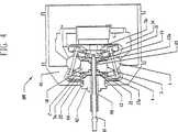
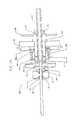
図1および図2を参照すると、無段変速機100の実施形態が開示されている。変速機100は、ハブシェル40に覆われ、ハブシェル40は、出力ディスクとして機能するとともに、(自転車またはオートバイのような)乗り物が駆動ホイール内に収容された変速機を有する応用例を含めて、種々の応用例において望ましい。いくつかの実施形態では、ハブキャップ67によって、ハブシェル40を覆うことができる。変速機100の中心には、形状を球状にすることができ、変速機100の中心線、すなわち回転軸線周りを円周方向にほぼ均等にまたは対称的に間隔を置いて配置される複数の速度調整器1がある。示した実施形態では、8つの速度調整器1が使用される。しかしながら、変速機100の使用によって異なるもっと多くのまたは少ない速度調整器1を使用可能であることに留意すべきである。例えば、変速機は、3、4、5、6、7、8、9、10、11、12、13、14または15個以上の速度調整器を含み得る。3、4または5個を超える速度調整器を設けることによって、例えば、個々の速度調整器1と、変速機100の他の構成要素に接する部分とにかかる力が広範囲に分配されることを含む利点をいくつか得られる。低トルクだが高変速比を有する応用例におけるいくつかの実施形態では、少数だが大型の速度調整器1を使用可能であり、また、高トルクで高変速比の応用例におけるいくつかの実施形態では、多数の大型の速度調整器1を使用可能である。高トルクおよび低変速比を有する応用例における他の実施形態は、多数の小型の速度調整器1を使用可能である。最後に、低トルクおよび低変速比を有する応用例におけるいくつかの実施形態では、ごく少数で小型の速度調整器1を使用可能である。 With reference to FIGS. 1 and 2, an embodiment of a continuously
スピンドル3が、各速度調整器1の回転軸線を画定するように、各速度調整器1の中心を通る孔から挿入される。スピンドル3は、速度調整器1が周りを回転する概ね細長い軸であり、速度調整器1を通る孔の各端部から延びる端部を2つ有する。どんな形状も用いることができるが、いくつかの実施形態では、円筒状に形成されたスピンドル3を有する。速度調整器1は、スピンドル3の周りを回転自在となるように装着される。図1では、速度調整器1の回転軸線は、およそ水平方向に(すなわち変速機100の主軸線と平行に)示されている。 A
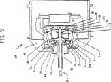
図1、図4および図5を用いて、変速機100をシフトさせる操作において速度調整器1の軸線をどのように傾斜させ得るかを説明することができる。図4は、低変速比またはローへシフトさせた変速機100を図示し、また図5は、高変速比またはハイへシフトさせた変速機100を図示する。ここで図9および図10も参照すると、複数のスピンドル支持物2が、速度調整器1を貫通する孔から延びる、スピンドル3の各端部近傍に取り付けられるとともに、その取付部分から変速機100の軸へ径方向内側へ延びる。一実施形態では、各スピンドル支持物2は、スピンドル3の1つの一方の端部を受け取る貫通孔を有する。スピンドル3は、露出した端部を有するようにスピンドル支持物2を通り越えて延びることが好ましい。示した実施形態では、スピンドル3は、スピンドル3の露出した両端上に同軸にかつ滑動するように位置するスピンドルローラ4を有すると有利である。スピンドルローラ4は、スピンドル支持物2の外側にかつそれを越えてスピンドル3に軸方向に固定された概ね円筒状のホイールであり、スピンドル3の周りを回転自在である。図11をさらに参照すると、スピンドルローラ4およびスピンドル3の両端部は、一対の固定支持物5a、5b内に切り込まれた溝6内に嵌合する。 1, 4, and 5, it can be described how the axis of the
図4、図5および図11を参照すると、固定支持物5a、5bは、概ね動力調整器1のいずれかの側に変速機の軸周りに環状に配置された平行なディスク形状である。速度調整器1の回転軸が、スピンドル支持物2を変速機100の軸から径方向外側に移動されてスピンドル3を傾けるように変化すると、各スピンドルローラ4は、固定支持物5a、5bの1つの中に切り込まれた溝6内に嵌合し、溝6を進む。速度調整器1がスピンドル3にかけ得る、径方向の力だが、回転力ではなく横断軸方向のどんな力も、スピンドル3、スピンドルローラ4、および固定支持物5a、5b内の溝6の側面81により吸収される。固定支持物5a、5bは、変速機100の軸に沿って配置された一対の分割型軸98、99に装着される。分割型軸98、99は、変速機100の軸方向の長さの実質的部分を画定し、それを用いる対象物に変速機100を連結するために使用可能な、概ね細長いシリンダである。各分割型軸98、99は、変速機100の中央近傍に内側端部と、変速機100の内部ハウジングから延びる外側端部とを有する。分割型軸98、99は、導入可能な他の任意の構成要素を収容するように中空であることが好ましい。各固定支持物5a、5bは、孔82を有し、その中を、分割型軸98と99が、挿入、固定され取り付けられて、分割型軸98、99と固定支持物5a、5bとの間のどんな相対的な動きも妨げられる。固定支持物5a、5bは、変速機100の中心に最も接近した、分割型軸98、99の両端に固定され取り付けられることが好ましい。固定支持ナット90を、分割型軸99に螺嵌し、固定支持物5a、5bの対応のねじ山において固定支持物5bに締め付け可能である。上に述べた固定支持物5a、5b内の溝6は、固定支持物5a、5bの外周から分割型軸98、99へ径方向内側へ延びる。ほとんどの実施形態では、溝6の溝側面81は、変速機100をシフトさせると、スピンドルローラ4が溝側面81を転がり得るように実質的に平行である。さらに、いくつかの実施形態では、溝6の深さは、固定支持物5a、5bの円周9において実質的に一定であるが、溝6の深さは、スピンドル3が傾けられるとスピンドル3の両端が描く弧に対応するように、かつ固定支持物5a、5bの強度を増すように、分割型軸98、99に近い方の部分7において浅くなっている。速度調整器1の回転軸を変えることにより変速機100をより低いまたは高い変速比へシフトさせると、1つのスピンドル3の反対の端部に配置された、スピンドルローラ4の各対は、対応する溝6に沿って逆向きに移動する。 Referring to FIGS. 4, 5, and 11, the fixed
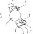
図9および図11を参照すると、固定支持物ホイール30が、固定支持物ホイールピン31でまたは他の取付方法によりスピンドル支持物2に取り付け可能である。固定支持物ホイール30は、固定支持物ホイールピン31に同軸にかつ滑動するように装着されるとともに、例えばリングクリップのような、一般的なファスナーで固定される。いくつかの実施形態では、1つの固定支持物ホイール30が、スピンドル2の各側に、変速機100をシフトさせる時に各固定支持物ホイール30が固定支持物5a、5bの凹状面84上を径方向に転がり得るのに十分なクリアランスを伴って、配置される。いくつかの実施形態において、凹状面84は、速度調整器1の中心と同心である。 9 and 11, a fixed
図2、図3および図11を参照すると、複数の細長いスペーサ8が、変速機の軸の周りに径方向に配置され概ね同軸に延びる。細長いスペーサ8は、変速機100の内部構造の強度および剛性を高めるために、相互に固定支持物5aを連結する。スペーサ8は、概ね相互に平行に向けられ、いくつかの実施形態では、各スペーサ8は、外周近傍において一方の固定支持物5aの一部分から他方の固定支持物5b上の対応する部分へ延びる。スペーサ8はまた、固定支持物5a、5b同士の間の間隔を正確に決め、固定支持物5a、5bの溝6を整列させ、固定支持物5a、5bが平行になることを保証し、分割型軸98、99の間に連結部分を形成する。一実施形態では、スペーサ8は、固定支持物5a、5b内のスペーサ孔46を貫通する。8本のスペーサ8を示すが、それよりも多いかまたは少ないスペーサ8を使用可能である。いくつかの実施形態では、スペーサ8は、2つの速度調整器1同士の間に配置される。 Referring to FIGS. 2, 3 and 11, a plurality of
図1、図3および図13を参照すると、固定支持物5aは、いくつかの実施形態では、分割型軸98周りに同軸に配置された固定支持スリーブ42に固定され取り付けられ、あるいはそうではなくその代わりに、分割型軸98の一体化した部分に固定され取り付けられるかまたはそのような部分になる。固定スリーブ42は、ハブシェル40の壁を通って延び、フレーム支持物15に付着する。いくつかの実施形態では、フレーム支持物15は、固定スリーブ42の上に同軸に嵌合し、固定スリーブ42に固定され取り付けられる。フレーム支持物15は、固定スリーブ42の固定位置を維持するように、いくつかの実施形態では、トルクレバー43を用いる。トルクレバー43は、フレーム支持物15を介して、物理的に固定スリーブ42を、よって固定部分の残りの部分を、変速機100が装着されることになるアイテムの固定した支持部材へ連結することにより、変速機100に回転安定性を供給する。トルクナット44が、固定スリーブ42の外側に螺着して、フレーム支持物15と係合する位置にトルクレバー43を保持する。いくつかの実施形態では、フレーム支持物15は、固定スリーブ42の回転を確実に妨げるようにトルクレバー43と係合させるために円筒状ではない。 With reference to FIGS. 1, 3 and 13, the fixed
例えば、フレーム支持物15は、トルクレバー43と厚さが等しい正方形にすることができ、その正方形は、固定スリーブより大きな側部を有するとともに、その正方形が固定スリーブ42上に嵌り次いで固定され取り付け可能となるように中心に孔が切り抜かれている。さらには、トルクレバー43は、フレーム支持物15の厚さと等しい厚さであり、フレーム支持物15近傍に第1の端部をかつ第1の端部と反対側に第2の端部を有するレバーアームにすることができる。トルクレバー43はまた、いくつかの実施形態において、その両端部の一方を通る孔を有するが、この孔は、正方形であり、トルクレバー43がフレーム支持物15上を滑動可能でありその結果フレーム支持物15とトルクレバー43とが回転係合するように、フレーム支持物15よりわずかに大きな正方形である。さらには、トルクレバー43のレバーアームは、第2の端部が、バイク、自動車、トラクター、あるいは変速機100が使用される他の応用例のフレームに取り付けられるように延びる方向に向けられて、それによって、フレーム支持物15および固定スリーブ42を通して変速機100により加えられるどんなトルクにも逆らう。固定支持物軸受48が、固定スリーブ42の周りに同軸に、かつハブシェル40の外側縁とトルクレバー43との間に軸方向に嵌合する。固定支持物軸受48は、ハブシェル40を支持し、ハブシェル40が固定支持物スリーブ42に対して回転することを可能にする。 For example, the
図1および図10を参照すると、いくつかの実施形態では、変速は、中空の分割型軸98内に配置されたロッド10を回転させることにより手動で行われる。ウォームスクリュー11、いくつかの実施形態では一連の雄ねじが、変速機100の中心にあるロッド10の端部へ取り付けられ、またロッド10の他方の端部は、変速機100の外部へ軸方向に延びるとともに、その外面に付けられたねじ山を有する。一実施形態では、ウォームスクリュー11は、噛み合うねじ溝を有する同軸スリーブ19内へ螺入し、その結果、スリーブ19は、ロッド10およびウォームスクリュー11が回転すると軸方向に移動する。スリーブ19は、概ね中空の円筒形状であり、ウォームスクリュー11およびロッド10の周りに同軸に嵌り、一方の端部を固定支持物5aの近くにかつもう一方の端部を固定支持物5bの近くに、2つの端部を有する。スリーブ19は、各端部においてプラットフォーム13、14に付けられる。2つの各プラットフォーム13、14は、概ね環状リング形状であり、内径が、スリーブ19に嵌りそれに取り付けられる程十分大きく、2つの側部を有するような形状になっている。第1の側部は、2組の接触軸受17a、17bを介して支持部材18と動的に接触しそれを軸方向に支持する概ね水平な面である。各プラットフォーム13、14の第2の側部は、凸状面形状である。プラットフォーム13、14は、それぞれスリーブ19の外側の一方の端部に取り付けられて、スリーブ19の円周周りに環状の雨樋(trough)を形成する。一方のプラットフォーム13は、固定支持物5aに最も近い側に取り付けられ、他方のプラットフォーム14は、固定支持物5bに最も近い側に取り付けられる。プラットフォーム13、14の凸状面は、カムとして機能し、それぞれ複数のシフトホイール21に接触し押圧する。このカム機能を果たすためには、プラットフォーム13、14は、(分割型軸98、99から最も遠い)周辺近傍において凸状の湾曲面97へ移行することが好ましく、それは円弧状にしてもよいしまたはそうしなくてもよい。この湾曲部97は、プラットフォーム13、14が軸方向に移動すると、シフトホイール21が概ね径方向にプラットフォーム13、14に沿って動くようにシフトホイール21と接して、スピンドル支持物2を分割型軸98、99から径方向外側へまたはそれらに向かって押しやり、それによって、スピンドル3の角度および関連の速度調整器1の回転軸が変わる。いくつかの実施形態では、シフトホイール21は、変速機100の中心線に最も近い端部でスピンドル支持物2内のスロット内へ嵌り、ホイール軸22によって所定位置に保持される。 With reference to FIGS. 1 and 10, in some embodiments, the shifting is performed manually by rotating a
図1および図10をなお参照すると、支持部材18は、プラットフォーム13、14とスリーブ19との間に形成された雨樋内に配置され、よってプラットフォーム13、14およびスリーブ19とともに一斉に移動する。いくつかの実施形態では、支持部材18は、概ね外径を1つ有し、かつ概ね内径の中心に沿った円筒形であり内径の各縁に軸受レースを有する。他の実施形態では、支持部材18の外径は、非均一とし、傾斜または湾曲したような任意の形状にすることができる。支持部材18は、固定支持物5aの一方の近くに1つの側部と、他方の固定支持物5bの近くに1つの側部と2つの側部を有する。支持部材18は、2つの接触軸受17a、17b上を動いて、支持部材18とスリーブ19との間に転がり接触を提供する。接触軸受17a、17bは、スリーブ19の周りに同軸に配置され、そこで、スリーブ19が、プラットフォーム13、14と相互作用して、支持部材18が変速機100の軸線周りを自由に回転し得る。スリーブ19は、ウォームスクリュー11およびロッド10により軸方向に支持され、したがってこの構成によって、スリーブ19は、ウォームスクリュー11が位置決めを行う時、軸方向に滑動可能となる。変速機100がシフトされる時、スリーブ19は、軸方向に移動し、軸受17a、17b、支持部材18およびプラットフォーム13、14は、すべてスリーブに動的または静的にいずれかで取り付けられ、対応して軸方向に移動する。 Still referring to FIGS. 1 and 10, the
いくつかの実施形態では、ロッド10は、ウォームスクリュー11の反対側の端部を、ロッドナット51によりシフトチューブ50に、かつロッドフランジ52に取り付けられる。シフトチューブ50は、一方の端部を開放しかつ他方の端部を実質的に閉鎖した概ねチューブ形状である。シフトチューブ50の開放端部は、変速機100の中心から軸方向に延びる、分割型軸98の端部に嵌るのに適切な直径である。シフトチューブ50の実質的に閉鎖した端部は、小さい貫通孔を有し、その結果、シフトチューブ50が分割型軸98の外側に配置されると、ウォームスクリュー11と反対側にあるロッド10の端部が、それを貫通可能となる。シフトチューブ50の実質的に閉鎖した端部は、次いで、ロッドナット51をシフトチューブ50の外側に締め付け、次いでロッドフランジ52をシフトチューブ50の実質的に閉鎖した端部内に締め付けることによって、軸方向の所定位置に固定可能である。シフトチューブ50は、いくつかの実施形態では、シフトチューブ50の外側へ取り付けたケーブル53により回転可能である。ケーブル53は、これらの実施形態において、ケーブルクランプ54およびケーブルねじ56でシフトチューブ50に取り付けられ、次いで、シフトチューブ50の周りを覆い、その結果、ケーブル53に張力がかかると、シフトチューブ50の軸線の中心周りにモーメントが生じて回転が起こる。シフトチューブ50の回転は、代わりに、手動回転によるロッド、サーボーモータのような他の機構、またはロッド10を回転させるために考えられた他の方法によって、行うことができる。いくつかの実施形態では、ケーブル53を引っ張って、シフトチューブ50が分割型軸98上を時計回りに回転すると、ウォームスクリュー11は、時計回りに回転し、スリーブ19、支持部材18およびプラットフォーム13、14をシフトチューブ50の方へ軸方向に引っ張り、変速機100を低変速比にシフトさせる。ウォームスプリング55が、図3に示すように、ウォームスクリュー11の端部に取り付けた、圧縮およびねじり力を生じ得る円すいコイルばねにすることができ、固定支持物5bとプラットフォーム14との間に配置され、変速機100のシフトに抵抗する。ウォームスプリング55は、いくつかの実施形態では低変速比へ、他の実施形態では高変速比へ変速機100をシフトする回転を行うためにシフトチューブ50を偏倚させるように設計されている。 In some embodiments, the
図1、図10および図11を参照すると、プラットフォーム13、14の軸方向の動きが、変速機100のシフト範囲を定める。 軸方向の動きは、プラットフォーム13、14が接触する、固定支持物5a、5b上の内面85により限定される。 極度に高い変速比では、プラットフォーム14は、固定支持物5a、5bの一方の内側面85と接触し、極度に低い変速比では、プラットフォーム13は、固定支持物5a、5bの他方の1つの内側面85と接触する。多くの実施形態では、プラットフォーム13、14の凸状の曲率半径は、速度調整器1の中心からホイール21の中心までの距離、ホイール21の半径、各速度調整器1に動作可能に取り付けられた2つのホイール21同士の間の距離、および速度調整器1の軸線の傾斜角度によって関数的に異なる。 With reference to FIGS. 1, 10 and 11, the axial movement of the
左巻きにねじ切りされたウォームスクリュー11が開示されているが、右巻きにねじ切りされたウォームスクリュー11、右巻きに巻かれる対応のシフトチューブ50、並びに支持部材18およびプラットフォーム13、14の横方向の動きを支持するために使用可能な、説明したばかりの種々の他の構成要素の組み合わせを使用可能である。さらに、シフトチューブ50は、分割型軸98の外側の外側ねじ山と係合する内側ねじ溝を持ち得る。この螺合を追加することによって、シフトチューブ50は、分割型軸98の周りを回転すると軸方向に移動して、ロッド10が同様に軸方向に移動する。これを用いて、ウォームスクリュー11によりスリーブ19の軸方向の動きを促進して、ウォームスクリュー11の回転作用を高め、歯車比をさらに迅速にシフトさせるか、あるいはウォームスクリュー11の回転作用を低くし、変速プロセスを緩やかにし変速機100の調整をより正確に行うことができる。 While a
図10および図18を参照すると、手動変速は、回転ハンドル132を使用することにより行うことができ、それは、固定チューブ、ハンドルバー130、またはある他の構造部材上に同軸に配置可能である。いくつかの実施形態では、ケーブル53の端部は、ケーブル止め133に留められ、ケーブル止め133は、回転ハンドル132に付けられる。いくつかの実施形態では、変速機100および円すいばね55の内力は、より低い変速比への変速機のシフトを偏倚させる傾向がある。回転ハンドル132が使用者により回転させられると、回転ハンドル132周りの溝に沿って巻き付け可能なケーブル53は、ケーブル53の回転方向によって巻き付いたりほどかれたりし、同時にシフトチューブ50を回転させ、変速機100をより高い変速比へシフトさせる。一連のラチェット歯134が、ラチェット付きチューブ135の第1の側において噛み合い用の一連のラチェット歯と係合するように回転ハンドル132の2つの側部の1つの側部の円周に配置可能であり、それによって、回転ハンドル132の逆方向への回転が妨げられる。可変の締付け力を可能にする調整可能なねじにすることができる、チューブクランプ136が、ラチェット付きチューブ135をハンドルバー130へ固定する。反対方向にシフトさせる時、回転ハンドル132は、反対方向に低い変速比へ強制回転させられて、チューブクランプ136が回転ハンドル132と一斉に回転する。ハンドルバーチューブ137が、ラチェット歯134と反対側に、ラチェット付きチューブ135に隣接して配置され、チューブクランプ138でハンドルバー130に堅固に締め付けられ、これによりラチェット付きチューブ135がラチェット歯134から係合解除されることが妨げられる。非回転ハンドル131が、ハンドルバー130に固定され回転ハンドル132に隣接して配置されて、回転ハンドル132の軸方向の動きを妨げ、かつラチェット歯134がラチェット付きチューブ135から係合解除されることが妨げられる。 Referring to FIGS. 10 and 18, manual shifting can be accomplished by using a
ここで、図1、図9および図11が示す実施形態を参照すると、1つまたはそれ以上の固定支持物ローラ30が、各スピンドル支持物2内の孔からローラピン31を挿入して各スピンドル支持物2に取付可能である。ローラピン31は、固定支持物ローラ30が各ローラピン31上を自由に回転することを可能にする適切なサイズおよび設計である。固定支持物ローラ30は、固定支持物5a、5bの、速度調整器1に面する側の凹状の湾曲面84に沿って回転する。固定支持物ローラ30は、スピンドル支持物2が軸方向に動くのを防ぐように、また変速機100をシフトさせる時にスピンドル2が容易に傾くことを保証するように、軸方向の支持を提供する。 Referring now to the embodiment shown in FIGS. 1, 9 and 11, one or more
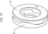
図1、図12、図14および図17を参照すると、3つのスポークが付いた駆動ディスク34が、固定支持物5bに隣接して配置され、固定支持物5bを部分的に内部に閉じこめるが、概ね固定支持物5bと接触はしない。 駆動ディスク34は、2つまたはそれ以上のスポークを有してもよし、または中実のディスクにしてもよい。スポークは、それらを使用する実施形態において、変速機100のアセンブリにおいて重量を低減し役に立つが、中実のディスクを使用可能である。駆動ディスク34は、速度調整器1と接する第1の側面と、第1の側面と反対を向いた第2の側面と、2つの側面を有する。駆動ディスク34は、内径で一連の雌ねじまたはナット37に同軸に嵌りそれから径方向に延びる概ね環状のディスクである。使用されたハブシェル40が速度調整器1および駆動ディスク34を内部に閉じこめハブキャップ67と係合するタイプである場合、駆動ディスク34の外径は、ハブシェル40内に納まるように設計されている。駆動ディスク34は、駆動ディスク34の第1の側面のリップにおいて円周軸受面に沿って速度調整器1に回転可能に連結される。上述のように、駆動ディスク34のいくつかの実施形態は、中心に、一連の雌ねじ37またはナット37を有し、ナット37は、ボルト35上に螺嵌され、それによってボルト35と駆動ディスク34とが係合する。ボルト35は、一連の中央ねじランプ90に固定され取り付けられ、中央ねじランプ90は、概ね、分割型軸99に同軸に配置された環状ディスクの一連の高くなった面である。中央ねじランプ90は、一連の中央駆動軸ランプ91により駆動され、中央駆動軸ランプ91は、概ね環状のディスク上に同様に形成される。中央駆動ランプ91および中央ねじランプ90の傾斜面は、直線状にすることができるが、種々の他の形状にすることができ、相互に作動可能に接触している。中央駆動軸ランプ91は、駆動軸69に同軸にかつ固定され取り付けられ、中央ねじランプ90にトルクおよび軸方向の力を与え、トルクおよび軸方向の力は、次に駆動ディスク34に伝達可能である。中央駆動引っ張り部材92が、中央駆動軸ランプ91と中央ねじランプ90との間に配置され、ねじりおよび/または圧縮力を生成し、中央ランプ90、91が相互に接することを保証する。 Referring to FIGS. 1, 12, 14 and 17, a
図1、図12、図14および図17をなお参照すると、ボルト35は、軸方向に可動であり、環状スラスト軸受73を、ボルト35の、速度調整器1に面する側のレースと接触させて、速度調整器1から軸方向に離れるように偏倚させることができる。環状のスラスト座金72が、分割型軸99上に同軸に配置され、スラスト軸受73と接触し、分割型軸99内のスロットを延びるピン12により押され得る。圧縮力を生成可能な圧縮部材95が、第1の端部において中空の分割型軸99の孔に配置される。圧縮部材95は、ばねにすることができ、一方の端部においてピン12と接触し、第2の端部でロッド10と接触する。 ロッド10は、より高い変速比へシフトされ軸方向に動くと、圧縮部材95と接触し、圧縮部材95をピン12に押しつける。変速機100内の内力は、一度変速比が1:1の変速比を超えてハイになると、支持部材18を偏倚させて高い変速比位置に動かし、駆動ディスク34が、ハブシェル40よりもさらにゆっくりと回転する。このように偏倚させることによって、ボルト35が、ナット37から離れるように軸方向に押されて、もはや駆動ディスク34に軸方向の力またはトルクがかからなくなるか、またはボルト35がナット37にかける力が減少する。 この状態において、外周ランプ61が駆動ディスク34にかける軸方向の力の割合が、増加する。変速機100の内力が、一度支持部材18が1:1の変速比位置を超えローになるとさらに支持部材18をローへ偏倚させ、ハブシェル40が駆動ディスク34よりもゆっくりと回転することに留意すべきである。この有利な偏倚は、ローへシフトする時、rpmが低下しトルクが増加する変速を支援する。 Still referring to FIGS. 1, 12, 14, and 17, the
なお図1、図12、図14および図17を参照すると、駆動軸69は、2つの端部を有する概ね管状のスリーブであり分割型軸99の外側に同軸に配置されており、一方の端部に前記中央駆動軸ランプ91が取り付けられ、また反対側の端部が駆動ディスク34から遠い方を向いている。いくつかの実施形態では、軸受ディスク60は、駆動軸69に取り付けられ、駆動軸69によって駆動される。軸受ディスク60では、軸受ディスク60の軸方向の動きを制限可能なキー溝を駆動軸69に形成可能であるか、あるいは軸受ディスク60は、駆動軸69に固定され取り付け可能である。軸受ディスク60は、通常放射状であり駆動軸69上に同軸に装着され、駆動ディスク34の半径と概ね等しい半径まで径方向外側へ延びる円盤である。軸受ディスク60は、駆動ディスク34近傍の位置において駆動軸69に、ただし駆動ディスク34と軸受ディスク60との間に配置される一連の外周ランプ61、関連のランプ軸受62、および軸受レース64用の空間をとるように十分離して装着される。いくつかの実施形態では、複数の外周ランプ61は、凹状にすることができ、軸受ディスク60の、駆動ディスク34の方を向いた側に固定され取り付けられる。あるいは、外周ランプ61は、変速機100の使用により異なるが、凸状または直線状にすることができる。あるいは、軸受レース64は、外周ランプ97の第2の組と取り替え可能であり、外周ランプ97の第2の組もまた、直線状、凸状、または凹状にすることができるとともに、駆動ディスク34の、軸受ディスク60の方を向いた側に固定され取り付けられる。ランプ軸受62は、概ね外周ランプ61の数と一致する複数の軸受である。複数の各ランプ軸受62は、1つの外周ランプ61と軸受レース64との間に配置され、ランプ61およびさらに軸受保持器63がかける圧縮力によって所定位置に保持される。 軸受保持器63は、分割型軸99と同軸の環状リングであり、凹状ランプ61と凸状ランプ64との間に軸方向に配置される。軸受保持器63は、比較的大きい内径を有し、その結果、軸受保持器63の径方向の厚さが、ランプ軸受62を収容するように、ランプ軸受62の直径よりもわずかだけ大きい。各ランプ軸受62は、軸受保持器63の径方向の厚さ内に形成される孔に嵌り、これらの孔は、前述の圧縮力とともに、ランプ軸受62を所定位置に保持する。軸受保持器63は、軸受保持器63の内径よりも若干小さい、駆動ディスク34または軸受ディスク60上のフランジによって所定位置へ案内され得る。Referring to FIGS. 1, 12, 14 and 17, the
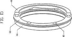
図1、図6、図7、図8および図15を参照すると、一実施形態の軸受ディスク60、外周ランプ61、およびランプ軸受62が、示されている。特に図6を参照すると、概略図が、凹状外周ランプ61および第2の凸状外周ランプ97と接触したランプ軸受62を示す。特に図7を参照すると、概略図が、異なるトルクまたは変速比における、図6のランプ軸受62、凹状外周ランプ61、および第2の凸状外周ランプ97を示す。図7に示す外周ランプ61上におけるランプ軸受62の位置は、図6に示す外周ランプ61上のランプ軸受62の位置よりも生じる軸方向の力が少ない。特に図8を参照すると、ランプ軸受62が、凸状外周ランプ61および凹状の第2の外周ランプ97上の実質的に中央の位置においてそれら各ランプと接触した状態で示される。外周ランプ61、97の湾曲を変化させることによって、種々の変速比で動力調整器1にかかる軸方向の力の大きさが変化して、それにより異なる歯車比における効率が最大限になり、トルクが変化することに留意すべきである。変速機100の用途により異なるが、湾曲したまたは直線状の外周ランプ61、97を種々に組み合わせることができる。操作を単純化しコストを低減するためには、いくつかの応用例において、外周ランプ97の第2の組のような、一連の外周ランプを排除することができ、次いで軸受レース64と取り替えられる。さらにコストを低減するためには、外周ランプ61の組に直線状の傾斜部分を具えることができる。 Referring to FIGS. 1, 6, 7, 8 and 15, one embodiment of a
図1を参照すると、2つの端部を有するコイルばね65が、駆動軸69周りを同軸に覆い、一方の端部が軸受ディスク60へ、他方の端部が駆動ディスク34へ取り付けられる。コイルばね65は、駆動ディスク34を速度調整器1と接触させておく力を提供し、ランプ軸受62を外周ランプ61上へ偏倚させる。コイルばね65は、作動する必要がある軸方向の空間を最小限にするように設計され、いくつかの実施形態では、コイルばね65の断面は、軸方向長さより長い径方向長さを有する矩形である。 Referring to FIG. 1, a
図1を参照すると、軸受ディスク60は、軸受ディスク60の、凹状ランプ61と反対を向いた側において外側ハブキャップ軸受66と接触するのが好ましい。外側ハブキャップ軸受66は、変速機100の径方向外側だがその中心線と同軸に配置されるころ軸受の環状の一組にすることができる。外側ハブキャップ軸受66は、ハブキャップ67および軸受ディスク60と接触して相互に相対的動きができる所定位置に径方向に配置される。ハブキャップ67は、概ね、中央に駆動軸69が差し込まれる孔を有し、かつハブシェル40内に嵌る外径を有する円盤状である。ハブキャップの内径は、内側ハブキャップ軸受96と係合し、この内側ハブキャップ軸受96は、ハブキャップ67と駆動軸69との間に配置され、ハブキャップ67と駆動軸69相互の径方向および軸方向の整列を維持する。ハブキャップ67の外径の縁は、変速機100の大部分を包むようにハブシェル40内へハブキャップ67が螺入され得るようにねじ切り可能である。スプロケットまたはプーリー38あるいは、例えば伝動装置のような他の駆動伝達系アダプタが、入力回転を提供するように回転する駆動軸69に固定され取り付けられ得る。駆動軸69は、円錐軸受70によって分割型軸99周りに同軸の位置に維持される。円錐軸受70は、分割型軸99の周りに同軸に装着された環状軸受であり、駆動軸69と分割型軸99との間の転がり接触を可能にする。円錐軸受70は、分割型軸99上に螺着する円錐ナット71によって、あるいは他の締め付け方法によって所定の軸方向位置に固定可能である。 Referring to FIG. 1, the
いくつかの実施形態の実施において、スプロケットまたはプーリ38からの入力回転が、駆動軸69へ伝達され、次いで、駆動軸69が、軸受ディスク60及び複数の外周ランプ61を回転させ、その結果、ランプ軸受62が、外周ランプ61を回転させ速度調整器1に対して駆動ディスク34を押し付ける。 ランプ軸受62はまた、外周ランプ61と凸状ランプ64との間に固定されしたがってそれらの間に回転エネルギーを伝達するので、駆動ディスク34に回転エネルギーを伝達する。回転エネルギーは、駆動ディスク34から速度調整器1へ伝達され、次いで、速度調整器1が、ハブシェル40を回転させ、変速機100の出力回転およびトルクを提供する。 In some implementations, the input rotation from the sprocket or
図16を参照すると、ラッチ115が、駆動ディスク34の、軸受ディスク60に面した側に固定され取り付けられ、フックレバー113の両端部の第1の端部に固定され取り付けられたフック114と係合する。ラッチ115の開口部下の係合領域は、フック114の幅より広く、駆動ディスク34と軸受ディスク60とが相互に動くと、フック114が、ラッチ115の範囲内において、軸線に対して、径方向に移動する余分な空間を提供する。フックレバー113は、概ね、フック114用の長手方向支持部材であり、フックレバー113は、第2の端部に、第1のヒンジピン111を介して中央ヒンジ119と係合する一体型フックヒンジ116を有する。中央ヒンジ119は、2つの端部を有する概ね細長い支持部材である駆動ディスクレバー112の第1の端部と一体となっている。駆動ディスクレバー112は、第2の端部に一体型駆動ディスクヒンジ117を有し、この一体型駆動ディスクヒンジ117は、第2のヒンジピン118の使用によってヒンジ支柱110と係合する。ヒンジ支柱110は、概ねフック114、フックレバー113、フックヒンジ116、第1のヒンジピン111、中央ヒンジ119、駆動ディスクレバー112、第2のヒンジピン118、および駆動ディスクヒンジ117を支持する基部であり、軸受ディスク60の、駆動ディスク34に面した側に固定され取り付けられる。ラッチ115とフック114とが係合すると、外周ランプ61上の領域へランプ軸受62が転がって駆動ディスク34に正確な量の軸方向の力が供給されなくなるということが妨げられる。これは、外周ランプ61によってランプ軸受62にかかる回転力がすべて駆動ディスク34に伝達されることを保証する。Referring to FIG. 16, the
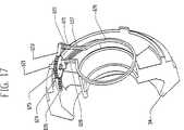
図1および図17を参照すると、惰性回転を行うために速度調整器1から駆動ディスク34の係合を解除する、変速機100の一実施形態用の係合解除機構が、説明されている。変速機100への入力回転が中止される場合、スプロケットまたはプーリ38は、回転を中止するが、ハブシェル40および速度調整器1は引き続き回転可能である。これによって、駆動ディスク34が、回転して、その結果、駆動ディスク34の孔の中の雌ねじ37の組が雄ねじ35に巻かれ、それにより駆動ディスク34が速度調整器1から軸方向に離れ駆動ディスク34が速度調整器1と接触しなくなる。歯付きラック126が、駆動ディスク34の、軸受ディスク60に面した側に固定され取り付けられ、駆動ディスク34がボルト35に巻かれると歯車124と係合し、動力調整器1との係合を解除されると歯車124を回転させる歯を有する。歯車124は、中心に孔を有し、その孔の中を通って歯車ブッシュ121が配置され、歯車124の回転を可能にする。どんな締め付け手段を使用してもよいが、歯車ブッシュ121上に同軸に取り付けられたクリップ125が、歯車124を所定位置に固定する。プレローダー120が、中央の駆動軸ランプ91に同軸に配置され締め付けられ、変速機100の中心から径方向外側向きに延びる。プレローダー120は、弾性材料からなり、曲げられると原形に戻り得、第1の端部128と第2の端部127とを有する。プレローダーの第1の端部128は、歯車ブッシュ121を通って延び、軸受保持器63で終わる。プレローダーの第1の端部128は、軸受保持器63およびランプ軸受62をランプ61に沿って偏倚させてランプ軸受62とランプ61との間の接触を保証し、また歯車124を歯付きラック126に偏倚させる。つめ123が、歯車124と係合し、一実施形態では、実質的に歯付きラック126の反対側において歯車124と係合する。 つめ123は、つめブッシュ122が貫通し、つめ123の回転を可能にする孔を有する。クリップ125、または他の締め付け固定手段が、つめ123をつめブッシュ121へ固定する。つめスプリング122が、歯車124と係合するようにつめ123の回転を偏倚させ、それにより駆動ディスク34がボルト35に巻かれる時に歯車124が逆回転することが妨げられる。つめブッシュ121は、プレローダー127の第2の端部上に配置され、駆動軸69とともに回転する。 With reference to FIGS. 1 and 17, a disengagement mechanism for one embodiment of the
図1を再度参照すると、コイルばね65が、駆動軸69と同軸でありその周りに配置されており、ピンまたは他の締め付け固定具(図示せず)によって、軸受ディスク60と駆動ディスク34との間に軸方向に配置され、一方の端部を軸受ディスク60にかつ他方の端部を駆動ディスク34に取り付けられる。いくつかの実施形態では、コイルばね65は、より多くの力を提供するために、かつ軸方向の空間を減らして変速機100全体の寸法を減少させるために、先行技術のコイルばねに取って代わる。いくつかの実施形態では、コイルばね65は、その軸方向の長さまたは幅より径方向に長いかまたは高い矩形の輪郭を有するばねワイヤーから製作される。変速機100の作動中に、コイルばね65は、速度調整器1と駆動ディスク34との間の接触を保証する。しかしながら、一度駆動ディスク34が速度調整器1との係合を解除されると、コイルばね65が、駆動ディスク34に巻き付いて、その結果、歯車124とつめ123とが係合することによって速度調整器1と再接触することが妨げられる。入力スプロケット、歯車またはプーリ38が回転を再開すると、つめ123もまた回転し、歯車124が回転可能となり、したがって、駆動ディスク34が、コイルばね65により生じるねじり力によって回転しボルト35から巻き戻され得る。つめ123と歯車124とは、プレローダーの第1の端部128が軸受保持器63に取り付けられていることから、プレローダーの第1の端部128がプレローダーの第2の端部127の約半分の速度で回転することによって、相対的に動き得る。さらに、軸受保持器63は、ランプ軸受62が軸受ディスク60の外周ランプ61上を転がっているので、軸受ディスク60の半分の速度で回転する。 Referring again to FIG. 1, the
ここで図19を参照すると、図1の変速機100の代替実施形態が開示されている。この実施形態では、出力ディスク201が、図1に示した変速機100のハブシェル40と入れ替わっている。駆動ディスク34と同様に、出力ディスク201は、速度調整器1に接触し、速度調整器1により回転する。 出力ディスク201は、出力ディスク201および固定ケースキャップ204の両方と接触する出力ディスク軸受202により支持される。ケースキャップ204は、ケースのボルト205または他のファスナーを備えた固定ケース203に固定され取り付けられる。固定ケース203は、フレームのような不動の物体、またはそれを使用する機械に取付可能である。歯車、スプロケットまたはプーリ206が、ケースキャップ204および固定ケース203の外側の出力ディスク201に同軸にかつ固定され取り付けられる。しかしながら、例えば歯車のような他のどんなタイプの出力手段でも使用可能である。追加の支持を行うための、ケースキャップ204に分割型軸98を固定し連結するねじれブレース207を追加可能である。 Referring now to FIG. 19, an alternative embodiment of the
ここで図20および図21を参照すると、図1の変速機100の代替実施形態が開示されている。固定支持物レース302が、固定支持物5aの、速度調整器1から遠い方を向いた側に追加され、固定支持物軸受301および回転するハブシェルレース303と係合して、回転ハブシェル40に対する固定支持物5aの正確な配列を維持する。 ねじれブレース304が、固定支持物5aに固定され取り付けられ、次いで、変速機300の作動中に固定支持物5a、5bが回転することを妨げるために固定外部構成要素に固定され取り付けられ得る。駆動軸軸受306が、駆動軸69の、速度調整器1に面した端部に配置され、駆動軸69の同じ端部内に形成された駆動軸レース307と、分割型軸99の径方向に高くなった部分に形成された分割型軸レース305とに係合して、駆動軸69をさらに支持するとともに、固定支持物5a、5bに対して駆動軸69を正確に位置決めする。図20に示す構成を用いる実施形態では、運動用シール(図示せず)が、ハブキャップ67の内径と、駆動軸69の、ハブキャップ67と駆動軸69とが異なる速度でしばしば回転し得る時ハブキャップ67に隣接する場所との間に利用可能である。シールは、回転するハブ40の内部に生じるほこりおよび砕片の量を最小限にするために使用可能である。 20 and 21, an alternative embodiment of the
ここで図22および図23を参照すると、図1の変速機100の代替係合解除機構400が開示されている。歯車402が、歯車ブッシュ408上に同軸に配置され、クリップ413または他のファスナーで回転可能な所定位置に固定される。歯車ブッシュ408は、(図22、図23では別々のものと見分けがつかないが)第1および第2の端部を有するプレローダー405の第1の端部上に同軸に配置される。プレローダー405は、弾性を伴って中央駆動軸ランプ91周りを締め付ける。プレローダー405の第1の端部は、軸受保持器63内へ延び、軸受保持器63を外周ランプ61上へ偏倚させる。歯車ブッシュ408上に配置されているのはまた、レバー401であり、レバー401は、歯車ブッシュ408周りを回転するとともに、歯車つめ411および小歯車つめ409を支持する。 歯車つめ411は、回転を制御するために歯車402と係合し、レバー401内の孔の中へ押し込まれる歯車ブッシュ414に配置される。歯車つめばね412が、歯車402に対して歯車つめ411を偏倚させる。レバー401上の歯車つめ411と実質的に反対側に位置する小歯車つめ409は、小歯車つめブッシュ415に同軸に配置され、小歯車ブッシュ415は、レバー401内の別の孔の中に嵌り、小歯車つめ409を回転運動させ得る。小歯車つめばね410が、小歯車403に対して小歯車つめ409を偏倚させる。 22 and 23, an
ここで、図1、図22および図23を参照すると、小歯車403は、中心に孔を有し、ロッドレバー404の2つの端部の第1の端部に同軸に配置される。ロッドレバーは、スプロケット、プーリまたは歯車38の入力回転が再開されるまでの惰性回転中に小歯車つめ409と係合する細長いレバーである。軸受ディスク60に固定される軸受ディスクピン406は、ロッドレバー404の第2の端部と接触しており、軸受ディスク60が回転すると、それにより、駆動ディスク34に固定され取り付けられた駆動ディスクピン407にロッドレバー404を押しつける。この動きは、ロッドレバー404の第1の端部を歯車402から揺動させ遠ざけ、歯車402から小歯車403を一時的に離し、歯車402を回転可能にする。レバーフック401aが、レバー401に取り付けられ、駆動ディスク34上のラッチ(図示せず)と接触し、それにより、コイルばね65が駆動ディスク34を偏倚させて巻き戻し速度調整器1と接触させている時には後退する。スプロケット、プーリまたは歯車38の入力回転が止まり速度調整器1が回転し続けている間に、駆動ディスク34は、ボルト35へ巻かれ、速度調整器1から係合解除される。駆動ディスク34が回転すると、駆動ディスクピン407は、ロッドレバー404から係合解除され、次いで、ロッドレバー404は、小歯車403を揺動させ歯車402と接触させ、駆動ディスク34が速度調整器1と再係合することが妨げられる。Here, referring to FIGS. 1, 22, and 23, the
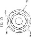
図24および図25を参照すると、図20の変速機300の軸方向力ジェネレーター500の代替セットの組立部品が開示されている。スプライン駆動軸501が、入力スプロケット、歯車あるいはプーリ38によって回転すると、スプライン駆動軸501は、軸受ディスク60を回転させ、軸受ディスク60は、孔の中において、スプライン駆動軸501のスプライン506を受け取り、係合する溝505を具え得る。中央駆動軸ランプ508は、軸受ディスク60またはスプライン駆動軸501に固定され取り付けられて、中央ねじランプ507を回転させ、これらの両方は、スプライン駆動軸501のスプライン506がない孔を有する。(図1に示した)中央引っ張り部材92は、中央の駆動軸ランプ508と中央のねじランプ507との間に配置される。溝付きの端部および軸受端部を有する溝付きねじ502が、中央ねじランプ507により回転させられるとともに、軸受端部に溝505を有し、この溝505は、スプライン駆動軸501上のスプライン506より幅が広く、スプライン506と溝505との間にギャップを提供する。スプライン506と溝505との間のこのギャップは、溝付きねじ502および/または軸受ディスク60と、スプライン駆動軸501との間の相対的動きを可能にする。溝付きねじ502が中央の駆動軸ランプ508および中央のねじランプ507によって回転しない場合、スプライン駆動軸501のスプライン506は、溝付きねじ502の溝505と接触し回転し、よって溝付きねじ502を回転させる。環状ねじ軸受503が、溝付きねじ502の軸受端部上のレースと接触し、ねじ溝つきねじ502およびスプライン駆動軸501を分割型軸99に対して支持するように配置される。溝付きねじ502の孔は、スプライン駆動軸501の外径よりも若干大きく、溝付きねじ502を軸方向に動かしかつ相対的に回転運動させることができる。ねじの円錐形レース504が、環状のねじ軸受503と接触および係合し、かつピン12を挿入できるように軸線に垂直な孔を有する。ピン12は、ロッド10と係合し、ロッド10は、ピン12を押し溝付きねじ502を軸方向に移動させることができ、その結果溝付きねじ502がナット37から係合解除されるかまたはナット37に掛ける軸方向の力が低減する。Referring to FIGS. 24 and 25, an alternative set of assembly parts of the
図26を参照すると、図22および図23の係合解除手段400の代替係合解除手段600が開示されている。レバー401を、小歯車つめ409および歯車つめ411の両方を装着するために用いられたT字形を除去するように変更して、その結果、新規なレバー601は、レバー601に取り付けられた歯車つめ411のみを有する。第2のレバー602が、第1の端部および第2の端部を有する。小歯車つめ409は、第2のレバー602の第1の端部へ作動可能に取り付けられる。第2のレバー602は、プレローダー405の第1の端部が挿入される、第1の孔を有する。第2のレバー602は、プレローダー405の第1の端部に回転可能に装着される。第2のレバー602は、プレローダー405の第2の端部が挿入される第2の端部に第2の孔を有する。スプロケット、歯車またはプーリ38の回転が終わっても、駆動ディスク34は、引き続き、順方向に回転しねじ35に巻かれ、速度調整器1から係合解除される。プレローダー405の第1の端部は、順方向に回転して、小歯車つめ409が小歯車403と接触し小歯車403を時計回りに回転させる。これによって、歯車402が、反時計回りに回転し、その結果、歯車つめ411は、歯車402の1つ又はそれ以上の歯を通過し、駆動ディスク34を固定し、ねじ35から巻き戻され速度調整器1と接触しないようにする。スプロケット、歯車またはプーリ38の回転が再開される時、プレローダー405の第2の端部は、回転し、第2のレバー602の第2の端部と接触して、小歯車つめ409が小歯車403から揺動し係合解除され、それにより、駆動ディスク34が巻き戻され速度調整器1と再係合する。Referring to FIG. 26, an alternative disengagement means 600 for the disengagement means 400 of FIGS. 22 and 23 is disclosed. The
ここで、このような説明を適宜行って、本発明の特別の改良および利点のうちのいくつかを説明していく。本発明のすべての実施形態においてこれらの改良の必ずしもすべてが見いだされるとは限らないことに留意する。 Such description will now be made as appropriate to describe some of the particular improvements and advantages of the present invention. Note that not all of these improvements may be found in all embodiments of the invention.
図1を参照すると、いくつかの実施形態におけるこの改良は、駆動ディスク34に、異なる荷重または用途に応じるように可変の軸方向力を供給することを含む。これは、複数の軸方向力ジェネレーターを使用することにより行うことができる。軸方向力の生成は、ボルト35とナット37との間で行われ、関連の中央の駆動軸ランプ91とねじランプ90が行い、それから外周ランプ61、64が行うように、入れ替わりに行うことができる。あるいは、ボルト35、中央ランプ90、91、および外周ランプ61、64は、軸方向力の生成を共に行うことができる。さらには、外周ランプ61、64)における軸方向力は、変化させ得る。これは、凹状ランプおよび凸状ランプを含めて、傾斜を変化させることができるランプを使用することにより行うことができる。図1、および図6から図8、並びに前出の詳細な説明を参照すると、軸受ディスク60に外周ランプ61の第1の組を固定し、この外周ランプは凹状にすることができ、この外周ランプにランプ軸受62が接触する実施形態が、開示されている。外周ランプ61の第1の組と反対の側には、外周ランプ97の第2の組があり、外周ランプ97は、駆動ディスク34に取り付けられ、凹状にすることができるとともにランプ軸受62と接触している。ランプ軸受62と接触する凹状のランプおよび凸状のランプを使用することによって、速度調整器1と支持部材18との位置調節に応じて駆動ディスク34上の軸方向の荷重を非線形に増減させ得る。 With reference to FIG. 1, this improvement in some embodiments includes supplying the
ある実施形態の別の改良は、ある高さのトルク伝達時に、より多くの回転の伝動および一定の軸方向のスラストを提供するように軸受ディスク60と駆動ディスク34とを確実に係合することを含む。上述の、図1に示した実施形態を参照すると、これは、例えば、フック114とラッチ115との組み合わせを使用することによって実行可能であって、その場合、フック114は、駆動ディスク34と軸受ディスク60との間においてランプ軸受62を収容する軸受保持器63に取り付けられ、ラッチ115は、ランプ軸受62がランプ面上の各制限位置に到達するとフック114と係合する駆動ディスク34に取り付けられる。例としてこのような配置を挙げたが、フック114およびラッチ115が、上述したのとは逆の構成要素に取り付け可能か、あるいは他の多くの機構が、ランプ軸受62の制限位置において軸受ディスク60と駆動ディスク34とをこのように確実に係合させるために使用され得ることを理解すべきである。 Another improvement of certain embodiments is to ensure engagement of the
前出の設計に関するある実施形態のさらなる改良は、(別々とは認識されない)放射状スポークを有する駆動ディスク34であり、変速機100のアセンブリー内において重量を減らし支持を行う。ある実施形態では、駆動ディスク34は、他の構成要素の間においてフック114およびラッチ115にアクセス可能で、相互に等距離の3つのスポークを有する。 A further improvement of certain embodiments relating to the above design is a
ある実施形態の別の改良は、駆動ディスク34と軸受ディスク60とが相対的に回転運動する時に駆動ディスク34を軸方向に移動させるためにアクメねじのようなねじ35を使用することを含む。図1に示した実施形態を参照すると、ねじ切りされた雄ねじ35が、駆動ディスク34の孔内において、一連の雌ねじ37またはナット37内へ螺入可能である。これによって、駆動ディスク34が、ニュートラルで惰性回転または回転している時のように、入力トルクを提供するのを止める時に、駆動ディスク34が速度調整器1との係合を解除可能となり、さらにいくらかの軸方向の力を速度調整器1へ提供することが容易になる。さらには、ねじ切りされた雄ねじ35もまた、一連の雌ねじ37によって駆動ディスク34に軸方向の力を送るように設計される。 Another improvement of certain embodiments includes the use of a
過去の発明に関するある実施形態のさらに別の改良が、より高いかより低い変速比へ変速機をシフトする、改良された方法からなる。再び、図1に示した実施形態を参照すると、この方法は、例えば左巻きにねじ切りされたウォームスクリュー11を含むねじ切りされたロッド10と、ケーブル53あるいは遠隔モータまたは他の遠隔手段により遠隔作動する、対応の右巻きにねじ切りされたシフトチューブ50またはスリーブとを使用することによって実行可能である。あるいは、左ねじは、ウォームスクリュー11およびシフトチューブの両方に使用可能か、またはねじ切りされていないシフトチューブ50を使用可能であり、シフトチューブ50の回転速度に対して変速機100の変速比に作用するのに適切なそれらの種々の組み合わせも使用可能である。さらに、オペレーターが適切なシフトチューブ50の位置を維持するのを支援するために、円すいばね55を使用可能である。ウォームスクリュー11は、好ましくは、軸方向に支持部材18を整列させるようにねじ切りされたスリーブ19と嵌合し、その結果、ウォームスクリュー11が回転すると、支持部材18は、軸方向に移動する。 Yet another improvement of certain embodiments relating to past inventions consists of an improved method of shifting the transmission to a higher or lower transmission ratio. Referring again to the embodiment shown in FIG. 1, the method is remotely actuated by a threaded
過去の発明に関するいくつかの実施形態の別の改良が、変速機100用の係合解除機構である。係合解除機構は、入力スプロケット、プーリまたは歯車38を逆回転可能にし、駆動ディスク34を速度調整器1から係合解除することにより、変速機100がニュートラルで惰性回転可能になる。 Another improvement of some embodiments relating to past inventions is a disengagement mechanism for the
前出の説明は、本発明のある実施形態を詳述する。しかしながら、本文における前記の説明が以下に詳細に行われているかに拘わらず、本発明が多くの方法で実施可能であることが理解されるだろう。さらに上述のように、留意すべきことは、本発明のある特徴または態様を説明する時に特定の用語を使用することが、その用語が関連性を有する本発明の特徴または態様の種々の特定の特徴を含むものに制限されるようにその用語がここで再定義されることを意味すると理解すべきではないことである。したがって、本発明の範囲は、添付の特許請求の範囲および種々の均等物によって解釈されるべきである。 The foregoing description details certain embodiments of the invention. It will be understood, however, that the present invention can be implemented in many ways, regardless of whether the foregoing description in the text is described in detail below. Further, as noted above, it should be noted that the use of a particular term when describing a feature or aspect of the present invention may indicate that various particular features or aspects of the invention with which the term is relevant It should not be understood to mean that the term is redefined herein to be limited to including features. Accordingly, the scope of the invention should be construed by the appended claims and various equivalents.
Claims (54)
Translated fromJapanese傾斜可能な回転軸線を有し、長手方向軸線から径方向外側に配置された複数の速度調整器と、
長手方向軸線周りを環状に回転可能であり、前記各速度調整器の第1の部分と接触し、前記速度調整器に面した第1の側面、および前記速度調整器から遠い方を向いた第2の側面を有する駆動ディスクと、
長手方向軸線周りを環状に回転可能であり、前記各速度調整器の第2の部分と接触する、従動ディスクと、
長手方向軸線周りを環状に回転可能であり、前記各速度調整器の第3の部分と接触する、概ね円筒形の支持部材と、
長手方向軸線周りを環状に回転可能であり、前記駆動ディスクに回転力を提供するように適合された軸受ディスクと、
前記駆動ディスクと軸受ディスクとの間に配置され、前記駆動ディスクに軸方向力の成分をかけるように構成され、それにより前記駆動ディスクと速度調整器との接触を改善する、少なくとも2つの軸方向力ジェネレータと、
前記一連の中央駆動軸ランプおよび一連の中央ねじランプを備え、前記少なくとも2つの軸方向力ジェネレータの少なくとも1つにトルクを提供する複数の中央ランプと、
を備え、
変速比を相応に変化させる軸方向力は、一連の高い変速比におけるよりも、一連の低い変速比における方が大きい、変速機。A continuously variable transmission having a longitudinal axis,
A plurality of speed regulators having a tiltable axis of rotation and arranged radially outward from the longitudinal axis;
A first side surface facing the speed regulator and facing away from the speed regulator, the first side surface of the speed regulator being in contact with the first portion of the speed regulator; A drive disk having two sides;
A follower disk that is annularly rotatable about a longitudinal axis and is in contact with a second portion of each speed regulator;
A generally cylindrical support member that is annularly rotatable about a longitudinal axis and that contacts a third portion of each of the speed regulators;
A bearing disk that is annularly rotatable about a longitudinal axis and is adapted to provide a rotational force to the drive disk;
At least two axial directions disposed between the drive disk and the bearing disk and configured to apply an axial force component to the drive disk, thereby improving contact between the drive disk and the speed regulator A force generator;
A plurality of central ramps comprising the series of central drive shaft ramps and a series of central screw ramps to provide torque to at least one of the at least two axial force generators;
Equipped witha,
A transmission in which the axial force that changes the gear ratio accordingly is greater at a series of lower gear ratios than at a series of higher gear ratios .
傾斜可能な回転軸線を有し、長手方向軸線から径方向外側に配置された複数の速度調整器と、
長手方向軸線周りを環状に回転可能であり、前記各速度調整器の第1の部分と接触し、前記速度調整器の方を向いた第1の側面、および前記速度調整器から遠い方を向いた第2の側面を有する駆動ディスクと、
長手方向軸線周りを環状に回転可能であり、前記速度調整器の第2の部分と接触する従動ディスクと、
長手方向軸線周りを環状に回転可能であり、前記駆動ディスクに回転力を伝達するように適合された軸受ディスクと、
長手方向軸線周りを環状に回転可能であり、前記速度調整器の第3の部分と接触し、前記駆動ディスクおよび従動ディスクをより緩やかに回転させるように適合された支持部材と、
長手方向軸線周りを環状に回転可能であり、前記駆動ディスクに回転力を提供するように適合された軸受ディスクと、
前記駆動ディスクと前記軸受ディスクとの間に配置され、前記駆動ディスクに軸方向力の成分をかけるように形成され、それにより前記駆動ディスクと前記速度調整器との間の接触が改良される、少なくとも2つの軸方向力ジェネレータと、
一連の中央駆動軸ランプおよび一連の中央ねじランプを備え、前記少なくとも2つの軸方向力ジェネレータの少なくとも1つにトルクを提供する複数の中央ランプと、
を備え、
変速比を相応に変化させる軸方向力は、一連の高い変速比におけるよりも、一連の低い変速比における方が大きい、無段変速機。A continuously variable transmission having a longitudinal axis,
A plurality of speed regulators having a tiltable axis of rotation and arranged radially outward from the longitudinal axis;
A first side surface that is annularly rotatable about a longitudinal axis, contacts the first portion of each speed regulator, faces the speed regulator, and faces away from the speed regulator. A drive disk having a second side;
A follower disk rotatable annularly about a longitudinal axis and in contact with a second portion of the speed regulator;
A bearing disk that is annularly rotatable about a longitudinal axis and is adapted to transmit a rotational force to the drive disk;
A support member that is annularly rotatable about a longitudinal axis, is in contact with a third portion of the speed regulator, and is adapted to rotate the drive and follower discs more slowly;
A bearing disk that is annularly rotatable about a longitudinal axis and is adapted to provide a rotational force to the drive disk;
Disposed between the drive disk and the bearing disk, and configured to apply an axial force component to the drive disk, thereby improving contact between the drive disk and the speed regulator; At least two axial force generators;
A plurality of central ramps comprising a series of central drive shaft ramps and a series of central screw ramps to provide torque to at least one of the at least two axial force generators;
With
A continuously variable transmission in which the axial force that changes the gear ratio accordingly is greater at a series of low gear ratios than at a series of high gear ratios .
傾斜可能な回転軸線を有し、長手方向軸線から径方向外側に配置された複数の速度調整器と、
長手方向軸線周りを環状に回転可能であり、前記各速度調整器の第1の部分と接触し、前記速度調整器の方を向いた第1の側面、および前記速度調整器から遠い方を向いた第2の側面を有する駆動ディスクと、
長手方向軸線周りを環状に回転可能であり、前記各速度調整器の第2の部分と接触する従動ディスクと、
長手方向軸線周りに環状に回転可能であり、前記速度調整器の第3の部分と接触する支持部材と、
長手方向軸周りを環状に回転可能であり前記駆動ディスクに回転力を伝達するように適合された軸受ディスクと、
前記駆動ディスクと前記軸受ディスクとの間に配置され、前記駆動ディスクに軸方向力の成分をかけるように形成され、それにより前記駆動ディスクと前記速度調整器との間の接触が改良される、少なくとも2つの軸方向力ジェネレータと、
一連の中央駆動軸ランプおよび一連の中央ねじランプを備え、前記少なくとも2つの軸方向力ジェネレータの少なくとも1つにトルクを提供する複数の中央ランプと、
前記駆動ディスクおよび軸受ディスクと係合するように適合されたフックおよびラッチを有する連結組立部品と、
を備え、
変速比を相応に変化させる軸方向力は、一連の高い変速比におけるよりも、一連の低い変速比における方が大きい、無段変速機。A continuously variable transmission having a longitudinal axis,
A plurality of speed regulators having a tiltable axis of rotation and arranged radially outward from the longitudinal axis;
A first side surface that is annularly rotatable about a longitudinal axis, contacts the first portion of each speed regulator, faces the speed regulator, and faces away from the speed regulator. A drive disk having a second side;
A follower disk rotatable annularly about a longitudinal axis and in contact with the second portion of each speed regulator;
A support member that is annularly rotatable about a longitudinal axis and in contact with the third portion of the speed regulator;
A bearing disk that is annularly rotatable about a longitudinal axis and is adapted to transmit rotational force to the drive disk;
Disposed between the drive disk and the bearing disk, and configured to apply an axial force component to the drive disk, thereby improving contact between the drive disk and the speed regulator; At least two axial force generators;
A plurality of central ramps comprising a series of central drive shaft ramps and a series of central screw ramps to provide torque to at least one of the at least two axial force generators;
A coupling assembly having hooks and latches adapted to engage the drive disk and bearing disk;
With
A continuously variable transmission in which the axial force that changes the gear ratio accordingly is greater at a series of low gear ratios than at a series of high gear ratios .
傾斜可能な回転軸線、および中心を通る孔を有し、長手方向軸線から径方向外側に配置された、複数の球形の速度調整器と、
概ね円筒形であり2つの端部を有し各速度調整器の孔に1つずつ配置されたスピンドルと、
プラットフォーム端部およびスピンドル端部を有する複数のスピンドル支持物であり、該スピンドル支持物は各スピンドルに2つずつ設けられ、各スピンドル支持 物のスピンドル端部は、前記複数のスピンドルのうち1つのスピンドルの2つの端部の一方と作動可能に係合する、前記複数のスピンドル支持物と、
少なくとも1つの固定支持物ホイールが、各スピンドル支持物のスピンドル端部へ回転可能に取り付けられる、複数の固定支持物ホイールと、
長手方向軸線周りを環状に回転可能であり、前記各速度調整器の第1の部分と接触し、前記速度調整器の方を向いた第1の側面、および前記速度調整器から遠い方を向いた第2の側面を有する駆動ディスクと、
長手方向軸線周りを環状に回転可能であり前記各速度調整器の第2の部分と接触する従動ディスクと、
長手方向軸線周りを環状に回転可能であり、前記駆動ディスクに回転力を提供するように適合された軸受ディスクと、
前記駆動ディスクと前記軸受ディスクとの間に配置され、前記駆動ディスクに軸方向力の成分をかけるように形成され、それにより前記駆動ディスクと前記速度調整器との間の接触が改良される、少なくとも2つの軸方向力ジェネレータと、
一連の中央駆動軸ランプおよび一連の中央ねじランプを備え、前記少なくとも2つの軸方向力ジェネレータの少なくとも1つにトルクを提供する複数の中央ランプと、
概ね円筒形で長手方向軸線周りを環状に回転可能であり各速度調整器の第3の部分と接触する支持部材と、
環状の第1および第2の固定支持物であり、各第1および第2の固定支持物は、前記速度調整器の方を向いた第1の側面および前記速度調整器から遠い方を向いた第2の側面を有し、前記第1および第2の固定支持物はまた、前記第1の側面に凹状面を有し、前記第1の固定支持物は、前記駆動ディスクに隣接して配置され、前記第2の固定支持物は前記従動ディスクに隣接して配置される、前記第1および第2の固定支持物と、
を備え、
変速比を相応に変化させる軸方向力は、一連の高い変速比におけるよりも、一連の低い変速比における方が大きい、無段変速機。A continuously variable transmission having a longitudinal axis,
A plurality of spherical speed regulators having a tiltable axis of rotation and a hole through the center and disposed radially outward from the longitudinal axis;
A spindle that is generally cylindrical and has two ends, one in each speed regulator bore;
A plurality of spindle supports having a platform end and a spindle end, each of which is provided with two spindle supports, the spindle end of each spindle support being a spindle of the plurality of spindles; A plurality of spindle supports operatively engaged with one of the two ends of the plurality of spindle supports;
A plurality of fixed support wheels, wherein at least one fixed support wheel is rotatably mounted to the spindle end of each spindle support;
A first side surface that is annularly rotatable about a longitudinal axis, contacts the first portion of each speed regulator, faces the speed regulator, and faces away from the speed regulator. A drive disk having a second side;
A follower disk rotatable annularly about a longitudinal axis and in contact with the second portion of each speed regulator;
A bearing disk that is annularly rotatable about a longitudinal axis and is adapted to provide a rotational force to the drive disk;
Disposed between the drive disk and the bearing disk, and configured to apply an axial force component to the drive disk, thereby improving contact between the drive disk and the speed regulator; At least two axial force generators;
A plurality of central ramps comprising a series of central drive shaft ramps and a series of central screw ramps to provide torque to at least one of the at least two axial force generators;
A support member that is generally cylindrical and rotatable annularly about a longitudinal axis and in contact with a third portion of each speed regulator;
Annular first and second fixed supports, each first and second fixed support facing the first side facing towards the speed regulator and facing away from the speed regulator Having a second side, the first and second fixed supports also have a concave surface on the first side, and the first fixed support is disposed adjacent to the drive disk. The second fixed support is disposed adjacent to the driven disk, and the first and second fixed supports;
With
A continuously variable transmission in which the axial force that changes the gear ratio accordingly is greater at a series of low gear ratios than at a series of high gear ratios .
該面は、前記スピンドルの端部の径方向の動きを制限するように形成され、それにより前記変速機の変速比が制限される請求項27に記載の変速機。A surface located radially inward from the concave surface of each fixed support;
28. The transmission of claim27 , wherein the surface is formed to limit radial movement of an end of the spindle, thereby limiting a transmission ratio of the transmission.
前記各スピンドルの端部は、前記スピンドル支持物を通って関連の溝内へ延び、各固定支持物ホイールは、対応の溝に隣接する対応の凹状面と回転係合する請求項27に記載の変速機。Both of the fixed supports further comprise a plurality of radial grooves corresponding to the radial movement path of each spindle end,
End of the respective spindle, extends into the spindle support was through relevant in the groove, the stationary support wheels, according to claim27, rotational engagement with the concave surface of the corresponding adjacent to a corresponding groove transmission.
前記各スピンドルローラは、前記スピンドルの1つの、前記スピンドル支持物を越えて延びる端部上に同軸に配置され、前記スピンドルローラは、変速機がシフトさせられると、前記スピンドルを案内するように前記溝と回転係合する請求項30に記載の変速機。A plurality of spindle rollers;
Each spindle roller is coaxially disposed on an end of one of the spindles that extends beyond the spindle support, and the spindle roller guides the spindle when a transmission is shifted. The transmission of claim30 , wherein the transmission is rotationally engaged with the groove.
前記第1の固定支持物の関連の溝と回転係合するように形成された前記複数の各スピンドルローラは、比較高い変速比では前記溝の第1の垂直側面と係合し、比較的低い変速比では前記溝内の第2の垂直側面と係合する請求項30に記載の変速機。Each groove further comprises first and second vertical sides,
Each of the plurality of spindle rollers configured to rotationally engage the associated groove of the first fixed support engages the first vertical side of the groove at a relatively high transmission ratio and is relatively low 31. A transmission according to claim30 , wherein the transmission engages with a second vertical side surface in the groove.
前記第2の固定支持物の関連の溝と回転係合するように形成された前記複数の各スピンドルローラは、比較的高い変速比では前記関連の溝の第2の垂直側面と係合し、比較的低い変速比では前記関連の溝の第1の垂直側面と係合する請求項30に記載の変速機。Each groove further comprises first and second vertical sides,
Each of the plurality of spindle rollers configured to rotationally engage with an associated groove of the second fixed support engages a second vertical side of the associated groove at a relatively high transmission ratio; 31. The transmission of claim30 , wherein the transmission engages a first vertical side of the associated groove at a relatively low transmission ratio.
前記スペーサが、前記固定支持物を相互連結するように適合されそれにより前記第2の固定支持物に対する前記第1の固定支持物の方向付けを維持する請求項27に記載の変速機。A plurality of spacers having a longitudinal axis and two ends;
28. The transmission of claim27 , wherein the spacer is adapted to interconnect the fixed support, thereby maintaining the orientation of the first fixed support relative to the second fixed support.
前記各孔は、前記スペーサのうち1つのスペーサの2つの端部の一方の挿入を受け入れるように適合される請求項34に記載の変速機。Each fixed support further comprises a plurality of holes,
35. The transmission of claim34 , wherein each hole is adapted to receive insertion of one of the two ends of one of the spacers.
長手方向軸線と同軸の概ね環状のディスクであり、前記支持部材の両側に配置され、前記支持部材から遠い方を向いたプラットフォーム側面を有する第1および第2のプラットフォームと、をさらに備え、
前記各プラットフォームは、プラットフォーム側面に凸面を有し、前記各プラットフォームホイールは、前記プラットフォームの軸方向の動きが前記変速機のシフトを引き起こすような、前記凸面の1つとの回転係合をするように形成された請求項27に記載の変速機。A plurality of platform wheels rotatably mounted on the end of the spindle support platform;
First and second platforms that are generally annular discs coaxial with a longitudinal axis and have platform sides disposed on opposite sides of the support member and facing away from the support member;
Each platform has a convex surface on the side of the platform, and each platform wheel is in rotational engagement with one of the convex surfaces such that axial movement of the platform causes a shift of the transmission. 28. A transmission according to claim27 formed.
傾斜可能な回転軸線、および中心を通る孔を有し、長手方向軸線から径方向外側に配置された複数の球状の速度調整器と、
概ね円筒形であり2つの端部を有し、各速度調整器の前記孔に1つずつ配置される複数のスピンドルと、
プラットフォーム端部およびスピンドル端部を有する複数のスピンドル支持物であり、該スピンドル支持物は各スピンドルに2つずつ設けられ、各スピンドル支持 物の前記スピンドル端部は、前記複数のスピンドルのうちの1つのスピンドルの2つの端部の1つと作動可能に係合する前記複数のスピンドル支持物と、
少なくとも1つの固定支持物ホイールが、各スピンドル支持物の前記スピンドル端部に回転可能に取り付けられる、前記複数の固定支持物ホイールと、
長手方向軸線周りを環状に回転可能であり、前記各速度調整器の第1の部分と接触し、前記速度調整器の方を向いた第1の側面、および前記速度調整器から遠い方を向いた第2の側面を有する駆動ディスクと、
長手方向軸線周りを環状に回転可能であり、前記各速度調整器の第2の部分と接触する従動ディスクと、
概ね円筒形であり、長手方向軸線周りを環状に回転可能であり、各速度調整器の第3の部分と接触する支持部材と、
長手方向軸線周りを環状に回転可能であり、回転力を前記駆動ディスクへ伝達するように適合された軸受ディスクと、
前記駆動ディスクと軸受ディスクとの間に配置され、前記駆動ディスクに軸方向力の成分をかけるように構成され、それにより前記駆動ディスクと速度調整器との接触を改善する、少なくとも2つの軸方向力ジェネレータと、
一連の中央駆動軸ランプおよび一連の中央ねじランプを備え、前記少なくとも2つの軸方向力ジェネレータと協働して、軸方向および回転力を前記駆動ディスクへ伝達するように適合された一連の中央ランプと、
前記速度調整器の方を向いた第1の側面、および前記速度調整器から遠い方を向いた第2の側面を有し、第1の側面に凹状面を有する第1の固定支持物と、
前記速度調整器の方を向いた第1の側面、および前記速度調整器から遠い方を向いた第2の側面を有し、前記第1の側面に凹状面を有する第2の固定支持物と、
前記軸受ディスクと駆動ディスクとの間に配置され、前記変速機内へ入力回転を供給する際に前記駆動ディスクを前記速度調整器と係合させるように適合されたコイルばねと、
を備え、
変速比を相応に変化させる軸方向力は、一連の高い変速比におけるよりも、一連の低い変速比における方が大きい、無段変速機。A continuously variable transmission having a longitudinal axis,
A plurality of spherical speed regulators having a tiltable axis of rotation, and a bore through the center, disposed radially outward from the longitudinal axis;
A plurality of spindles that are generally cylindrical and have two ends, one in each of the holes of each speed regulator;
A plurality of spindle supports having a platform end and a spindle end, wherein two spindle supports are provided on each spindle, and the spindle end of each spindle support is one of the plurality of spindles; A plurality of spindle supports operatively engaged with one of the two ends of a spindle;
A plurality of fixed support wheels, wherein at least one fixed support wheel is rotatably attached to the spindle end of each spindle support;
A first side surface that is annularly rotatable about a longitudinal axis, contacts the first portion of each speed regulator, faces the speed regulator, and faces away from the speed regulator. A drive disk having a second side;
A follower disk rotatable annularly about a longitudinal axis and in contact with the second portion of each speed regulator;
A support member that is generally cylindrical, is capable of rotating annularly about a longitudinal axis, and is in contact with a third portion of each speed regulator;
A bearing disk that is annularly rotatable about a longitudinal axis and is adapted to transmit rotational force to the drive disk;
At least two axial directions disposed between the drive disk and the bearing disk and configured to apply an axial force component to the drive disk, thereby improving contact between the drive disk and the speed regulator A force generator ;
Comprises a series of central drive shaft lamp and a series of central screw lamp, wherein at least two in cooperation with axial force generators, the axial direction and adapted the rotational force so as to transmit to the drive disc by aseries of center lamp When,
A first fixed support having a first side facing toward the speed regulator and a second side facing away from the speed regulator and having a concave surface on the first side;
A second fixed support having a first side facing toward the speed regulator and a second side facing away from the speed regulator and having a concave surface on the first side; ,
A coil spring disposed between the bearing disk and the drive disk and adapted to engage the drive disk with the speed regulator when providing input rotation into the transmission;
With
A continuously variable transmission in which the axial force that changes the gear ratio accordingly is greater at a series of low gear ratios than at a series of high gear ratios .
第1および第2の端部を有しかつ前記分割型軸内に同軸に配置されたロッドと、
前記ロッドの第1の端部に取り付けられかつ一連の外側ねじ山を有するウォームスクリ ューと、
前記ウォームスクリューの周りに嵌りかつ前記ウォームスクリューの外側ねじ山と係合する一連の内部ねじ溝を有し、前記変速機の変速比を変更するためのスリーブと、
前記ロッドの第2の端部と係合し、かつ前記分割型軸のねじ切りされた端部に嵌り係合する一連の内側ねじ溝を有するシフトチューブであって、前記シフトチュー ブの回転によって、前記スリーブが軸方向に動き、それに伴い変速比が変化する前記シフトチューブと、
をさらに備える請求項41に記載の変速機。A split shaft that is generally tubular and coaxial with the longitudinal axis of the transmission and having a threaded end;
A rod having first and second ends and disposed coaxially within the split mold axis;
A worm screw attached to the first end of the rod and having a series of outer threads;
A series of internal thread grooves that fit around the worm screw and engage an outer thread of the worm screw, and a sleeve for changing a transmission ratio of the transmission;
A shift tube having a series of inner threaded grooves that engage the second end of the rod and fit into and engage with the threaded end of the split shaft; by rotation of the shift tube; The shift tube in which the sleeve moves in the axial direction and the gear ratio changes accordingly,
The transmission according to claim41 , further comprising:
前記ウォームスプリングは、前記変速機の長手方向軸線に同軸に嵌るとともに、前記第1の端部を前記ロッドに取り付けられかつ前記第2の端部を固定物体に取り付けられる請求項45に記載の変速機。The worm spring includes a conical spring having a first end and a second end;
46. The speed change according to claim45 , wherein the worm spring is fitted coaxially to a longitudinal axis of the transmission, and the first end is attached to the rod and the second end is attached to a fixed object. Machine.
回転可能なハンドルと、
第1の端部および第2の端部を有する綱状体と、を備え、
前記第1の端部は前記ハンドルと係合し、かつ前記第2の端部は前記シフトチューブと係合し、前記ハンドルは、前記綱状体に張力をかけるように適合され、前記 綱状体は、張力がかかると前記シフトチューブを回転させるように適合された、遠隔シフターをさらに備える請求項44に記載の変速機。And a remote shifter, the remote shifter
A rotatable handle,
A rope having a first end and a second end;
The first end engages the handle and the second end engages the shift tube; the handle is adapted to tension the rope; 45. The transmission of claim44 , wherein the body further comprises a remote shifter adapted to rotate the shift tube when tensioned.
傾斜可能な回転軸線を有し、長手方向軸線から径方向外側に配置された複数の速度調整器と、
長手方向軸線周りを環状に回転可能であり、前記各速度調整器の第1の部分と接触し、前記速度調整器の方を向いた第1の側面、および前記速度調整器から遠い方を向いた第2の側面を有する駆動ディスクと、
長手方向軸線周りを環状に回転可能であり、前記各速度調整器の第2の部分と接触する従動ディスクと、
概ね円筒形で長手方向軸線周りを環状に回転可能であり、前記各速度調整器の第3の部分と接触する支持部材と、
長手方向軸線周りを環状に回転可能であり、回転力を前記駆動ディスクに伝達するように適合された軸受ディスクと、
前記駆動ディスクと軸受ディスクとの間に配置され、軸方向力を前記駆動ディスクにかけるように適合された少なくとも2つの軸方向力ジェネレータと、
一連の中央駆動軸ランプおよび一連の中央ねじランプを備え、前記軸方向力ジェネレータの少なくとも1つに作動可能に連結された複数の中央ランプと、
概ね円筒形であり外径面を有し、トルクを前記駆動ディスクへ伝達するように作動可能に形成された駆動軸と、
を備え、
変速比を相応に変化させる軸方向力は、一連の高い変速比におけるよりも、一連の低い変速比における方が大きい、無段変速機。A continuously variable transmission having a longitudinal axis,
A plurality of speed regulators having a tiltable axis of rotation and arranged radially outward from the longitudinal axis;
A first side surface that is annularly rotatable about a longitudinal axis, contacts the first portion of each speed regulator, faces the speed regulator, and faces away from the speed regulator. A drive disk having a second side;
A follower disk rotatable annularly about a longitudinal axis and in contact with the second portion of each speed regulator;
A support member that is generally cylindrical and rotatable annularly about a longitudinal axis, and in contact with the third portion of each speed regulator;
A bearing disk that is annularly rotatable about a longitudinal axis and is adapted to transmit rotational force to the drive disk;
At least two axial force generators disposed between the drive disk and the bearing disk and adapted to apply an axial force to the drive disk;
A plurality of central ramps comprising a series of central drive shaft ramps and a series of central screw ramps operably coupled to at least one of the axial force generators;
A drive shaft that is generally cylindrical and has an outer diameter surface and is operatively configured to transmit torque to the drive disk;
With
A continuously variable transmission in which the axial force that changes the gear ratio accordingly is greater at a series of low gear ratios than at a series of high gear ratios .
前記ねじの第1の端部のレースと作動可能に接触しかつ同軸に配置されるとともに、前記ねじの第1の端部に隣接して軸方向に配置された環状軸受と、
をさらに備える請求項48に記載の変速機。A screw having a first end that is generally tubular, coaxial with the longitudinal axis, has a threaded outer surface, faces the speed regulator and has a bearing race on its inner diameter;
An annular bearing operatively contacting and coaxially disposed with a race at the first end of the screw and axially disposed adjacent to the first end of the screw;
49. The transmission of claim48 , further comprising:
Applications Claiming Priority (3)
| Application Number | Priority Date | Filing Date | Title |
|---|---|---|---|
| US28680301P | 2001-04-26 | 2001-04-26 | |
| US60/286,803 | 2001-04-26 | ||
| PCT/US2002/013399WO2002088573A2 (en) | 2001-04-26 | 2002-04-25 | Continuously variable transmission |
Publications (3)
| Publication Number | Publication Date |
|---|---|
| JP2004530847A JP2004530847A (en) | 2004-10-07 |
| JP2004530847A5 JP2004530847A5 (en) | 2006-01-26 |
| JP4332699B2true JP4332699B2 (en) | 2009-09-16 |
Family
ID=23100215
Family Applications (1)
| Application Number | Title | Priority Date | Filing Date |
|---|---|---|---|
| JP2002585835AExpired - Fee RelatedJP4332699B2 (en) | 2001-04-26 | 2002-04-25 | Continuously variable transmission |
Country Status (12)
| Country | Link |
|---|---|
| US (16) | US6689012B2 (en) |
| EP (2) | EP1384015B1 (en) |
| JP (1) | JP4332699B2 (en) |
| KR (6) | KR100854795B1 (en) |
| CN (3) | CN101526133B (en) |
| AT (1) | ATE493603T1 (en) |
| AU (6) | AU2002303524B2 (en) |
| CA (3) | CA2722124C (en) |
| DE (1) | DE60238755D1 (en) |
| MX (1) | MXPA03009830A (en) |
| RU (1) | RU2289045C2 (en) |
| WO (1) | WO2002088573A2 (en) |
Families Citing this family (101)
| Publication number | Priority date | Publication date | Assignee | Title |
|---|---|---|---|---|
| US6551210B2 (en) | 2000-10-24 | 2003-04-22 | Motion Technologies, Llc. | Continuously variable transmission |
| US7296815B2 (en)* | 1998-03-02 | 2007-11-20 | Anthony S. Ellsworth | Bicycle suspension apparatus and related method |
| KR100854795B1 (en)* | 2001-04-26 | 2008-08-27 | 모션 테크놀로지즈 엘엘씨 | Device for speed ratio adjustment of roller traction transmission and continuous variable transmission |
| US7011600B2 (en)* | 2003-02-28 | 2006-03-14 | Fallbrook Technologies Inc. | Continuously variable transmission |
| US7166052B2 (en) | 2003-08-11 | 2007-01-23 | Fallbrook Technologies Inc. | Continuously variable planetary gear set |
| US7214159B2 (en) | 2003-08-11 | 2007-05-08 | Fallbrook Technologies Inc. | Continuously variable planetary gear set |
| EP1774199B1 (en)* | 2004-07-21 | 2013-06-12 | Fallbrook Intellectual Property Company LLC | Rolling traction planetary drive |
| WO2006041718A2 (en)* | 2004-10-05 | 2006-04-20 | Fallbrook Technologies, Inc. | Continuously variable transmission |
| US7309081B1 (en) | 2005-06-20 | 2007-12-18 | Zuhlsdorf David A | Four wheel off-road vehicle |
| WO2007044128A2 (en)* | 2005-08-22 | 2007-04-19 | Viryd Technologies Inc. | Fluid energy converter |
| US7670243B2 (en)* | 2005-08-24 | 2010-03-02 | Fallbrook Technologies, Inc. | Continuously variable transmission |
| SE531288C2 (en)* | 2005-09-13 | 2009-02-17 | Kongsberg Automotive As | Cable valve |
| WO2007070167A2 (en) | 2005-10-28 | 2007-06-21 | Fallbrook Technologies Inc. | Electromotive drives |
| PL1954959T3 (en) | 2005-11-22 | 2013-10-31 | Fallbrook Ip Co Llc | Continuously variable transmission |
| CN102221073B (en)* | 2005-12-09 | 2013-03-27 | 福博科技术公司 | Continuously variable transmission |
| EP1811202A1 (en)* | 2005-12-30 | 2007-07-25 | Fallbrook Technologies, Inc. | A continuously variable gear transmission |
| US7882762B2 (en)* | 2006-01-30 | 2011-02-08 | Fallbrook Technologies Inc. | System for manipulating a continuously variable transmission |
| WO2007106874A2 (en)* | 2006-03-14 | 2007-09-20 | Autocraft Industries, Inc. | Improved wheelchair |
| US20080070729A1 (en)* | 2006-05-11 | 2008-03-20 | Fallbrook Technologies Inc. | Continuously variable drivetrain |
| CN102269055B (en) | 2006-06-26 | 2013-08-28 | 福博科技术公司 | Continuously variable transmission |
| PL2089642T3 (en) | 2006-11-08 | 2013-09-30 | Fallbrook Ip Co Llc | Clamping force generator |
| EP2125469A2 (en)* | 2007-02-01 | 2009-12-02 | Fallbrook Technologies Inc. | System and methods for control of transmission and/or prime mover |
| US20100093479A1 (en) | 2007-02-12 | 2010-04-15 | Fallbrook Technologies Inc. | Continuously variable transmissions and methods therefor |
| TWI461615B (en) | 2007-02-16 | 2014-11-21 | Fallbrook Ip Co Llc | Infinitely variable transmissions, continuously variable transmissions, methods, assemblies, subassemblies, and components therefor |
| EP2142826B1 (en)* | 2007-04-24 | 2015-10-28 | Fallbrook Intellectual Property Company LLC | Electric traction drives |
| US8641577B2 (en)* | 2007-06-11 | 2014-02-04 | Fallbrook Intellectual Property Company Llc | Continuously variable transmission |
| CN103697120B (en) | 2007-07-05 | 2017-04-12 | 福博科技术公司 | Continuously variable transmission |
| US7887032B2 (en)* | 2007-11-07 | 2011-02-15 | Fallbrook Technologies Inc. | Self-centering control rod |
| CN103939602B (en) | 2007-11-16 | 2016-12-07 | 福博科知识产权有限责任公司 | Controllers for variable speed drives |
| US8321097B2 (en) | 2007-12-21 | 2012-11-27 | Fallbrook Intellectual Property Company Llc | Automatic transmissions and methods therefor |
| US8313405B2 (en)* | 2008-02-29 | 2012-11-20 | Fallbrook Intellectual Property Company Llc | Continuously and/or infinitely variable transmissions and methods therefor |
| US8317651B2 (en) | 2008-05-07 | 2012-11-27 | Fallbrook Intellectual Property Company Llc | Assemblies and methods for clamping force generation |
| CN102112778B (en) | 2008-06-06 | 2013-10-16 | 福博科技术公司 | Infinitely variable transmission, continuously variable transmission, methods, assemblies, subassemblies and components therefor |
| KR101008187B1 (en)* | 2008-06-16 | 2011-01-14 | 오토스테크 주식회사 | Welding mask with functional gasket |
| EP2304272B1 (en) | 2008-06-23 | 2017-03-08 | Fallbrook Intellectual Property Company LLC | Continuously variable transmission |
| DE102008031438A1 (en) | 2008-07-04 | 2010-02-04 | Clean Mobile Ag | Vehicle with automatic transmission |
| CA2732668C (en) | 2008-08-05 | 2017-11-14 | Fallbrook Technologies Inc. | Methods for control of transmission and prime mover |
| US8469856B2 (en) | 2008-08-26 | 2013-06-25 | Fallbrook Intellectual Property Company Llc | Continuously variable transmission |
| WO2010032890A1 (en)* | 2008-09-20 | 2010-03-25 | Sun Choung Kim | Continuously variable transmission |
| ES2423934T3 (en) | 2008-10-14 | 2013-09-25 | Fallbrook Intellectual Property Company Llc | Continuously variable transmission |
| US8167759B2 (en) | 2008-10-14 | 2012-05-01 | Fallbrook Technologies Inc. | Continuously variable transmission |
| KR20100055352A (en)* | 2008-11-17 | 2010-05-26 | 변동환 | Continuously variable transmission |
| US9464701B2 (en)* | 2009-01-22 | 2016-10-11 | Orbital Traction, Ltd. | Fluid movement systems including a continuously variable transmission |
| ES2439647T3 (en) | 2009-04-16 | 2014-01-24 | Fallbrook Intellectual Property Company Llc | Stator set and speed change mechanism for a continuously variable transmission |
| KR101035207B1 (en)* | 2009-11-12 | 2011-05-17 | 최정용 | Continuously variable transmission |
| CN102144113B (en)* | 2009-12-02 | 2014-02-05 | 丰田自动车株式会社 | Stepless transmission |
| US8382636B2 (en)* | 2009-12-02 | 2013-02-26 | Toyota Jidosha Kabushiki Kaisha | Continuously variable transmission |
| KR101026005B1 (en)* | 2010-01-29 | 2011-03-30 | 최정용 | Continuously variable speed gear for bicycle |
| US8512195B2 (en)* | 2010-03-03 | 2013-08-20 | Fallbrook Intellectual Property Company Llc | Infinitely variable transmissions, continuously variable transmissions, methods, assemblies, subassemblies, and components therefor |
| GB2488506A (en) | 2010-04-15 | 2012-09-05 | Orbital Traction Ltd A Texas Ltd Partnership | Continuously variable transmission with non-linear end clamping force |
| US9631563B2 (en) | 2010-06-30 | 2017-04-25 | Orbital Traction, Ltd | Torque pulse dampener |
| US8888643B2 (en) | 2010-11-10 | 2014-11-18 | Fallbrook Intellectual Property Company Llc | Continuously variable transmission |
| AU2012240435B2 (en) | 2011-04-04 | 2016-04-28 | Fallbrook Intellectual Property Company Llc | Auxiliary power unit having a continuously variable transmission |
| US8836157B2 (en)* | 2011-05-26 | 2014-09-16 | Hoang Luu Vo | Power generation device |
| RU2492097C2 (en)* | 2011-06-22 | 2013-09-10 | Анатолий Исаакович Хмельницкий | Bicycle stepless transmission |
| EP2764305A2 (en) | 2011-10-03 | 2014-08-13 | Fallbrook Intellectual Property Company LLC | Refrigeration system having a continuously variable transmission |
| CN104302949B (en) | 2012-01-23 | 2017-05-03 | 福博科知识产权有限责任公司 | Infinitely variable continuously variable transmission, continuously variable continuously variable transmission, method, assembly, subassembly, and parts thereof |
| CN104204615B (en) | 2012-02-15 | 2017-10-24 | 德纳有限公司 | Transmission device and the power train with tilt ball speed changer infinitely variable speed transmission |
| EP2893219A4 (en) | 2012-09-06 | 2016-12-28 | Dana Ltd | Transmission having a continuously or infinitely variable variator drive |
| WO2014039713A1 (en) | 2012-09-07 | 2014-03-13 | Dana Limited | Ivt based on a ball type cvp including powersplit paths |
| US9689477B2 (en) | 2012-09-07 | 2017-06-27 | Dana Limited | Ball type continuously variable transmission/infinitely variable transmission |
| WO2014039708A1 (en) | 2012-09-07 | 2014-03-13 | Dana Limited | Ball type cvt including a direct drive mode |
| US9599204B2 (en) | 2012-09-07 | 2017-03-21 | Dana Limited | Ball type CVT with output coupled powerpaths |
| US10030748B2 (en) | 2012-11-17 | 2018-07-24 | Dana Limited | Continuously variable transmission |
| US9429217B2 (en) | 2013-01-28 | 2016-08-30 | Robert Hornblower Meyer | Continuously variable drive mechanism |
| WO2014124063A1 (en) | 2013-02-08 | 2014-08-14 | Microsoft Corporation | Pervasive service providing device-specific updates |
| US9322461B2 (en) | 2013-03-14 | 2016-04-26 | Team Industries, Inc. | Continuously variable transmission with input/output planetary ratio assembly |
| US9133918B2 (en) | 2013-03-14 | 2015-09-15 | Team Industries, Inc. | Continuously variable transmission with differential controlling assemblies |
| US8814739B1 (en) | 2013-03-14 | 2014-08-26 | Team Industries, Inc. | Continuously variable transmission with an axial sun-idler controller |
| CN105121905A (en) | 2013-03-14 | 2015-12-02 | 德纳有限公司 | Ball type continuously variable transmission |
| US8827856B1 (en) | 2013-03-14 | 2014-09-09 | Team Industries, Inc. | Infinitely variable transmission with an IVT stator controlling assembly |
| US9057439B2 (en)* | 2013-03-14 | 2015-06-16 | Team Industries, Inc. | Infinitely variable transmission with IVT traction ring controlling assemblies |
| US9551404B2 (en) | 2013-03-14 | 2017-01-24 | Dana Limited | Continuously variable transmission and an infinitely variable transmission variator drive |
| KR102433297B1 (en) | 2013-04-19 | 2022-08-16 | 폴브룩 인텔렉츄얼 프로퍼티 컴퍼니 엘엘씨 | Continuously variable transmission |
| EP3004686B1 (en) | 2013-06-06 | 2018-08-08 | Dana Limited | 3-mode front wheel drive and rear wheel drive continuously variable planetary transmission |
| JP2015075185A (en)* | 2013-10-10 | 2015-04-20 | 日本精工株式会社 | Single cavity type toroidal type continuously variable transmission |
| US9115793B2 (en)* | 2013-10-15 | 2015-08-25 | Schlumberger Technology Corporation | Controllable mechanical transmission for downhole applications |
| WO2015073948A2 (en) | 2013-11-18 | 2015-05-21 | Dana Limited | Torque peak detection and control mechanism for cvp |
| US10030751B2 (en) | 2013-11-18 | 2018-07-24 | Dana Limited | Infinite variable transmission with planetary gear set |
| ITMI20131995A1 (en) | 2013-11-29 | 2015-05-30 | Cms Spa | VARIABLE TRANSMISSION REPORT DEVICE |
| ES2554181B1 (en)* | 2014-06-12 | 2016-06-09 | José Antonio CARAMÉS JIMÉNEZ | Continuously Variable Automatic Transmission |
| CN106536987A (en) | 2014-06-17 | 2017-03-22 | 德纳有限公司 | Off-highway continuously variable planetary-based multimore transmission including infinite variable transmission and direct continuously variable tranmission |
| WO2016168439A1 (en)* | 2015-04-17 | 2016-10-20 | Dana Limited | Passive centrifugal hydraulic clamping for high-speed continuously variable planetary operation |
| US10030594B2 (en) | 2015-09-18 | 2018-07-24 | Dana Limited | Abuse mode torque limiting control method for a ball-type continuously variable transmission |
| DE102015222062A1 (en)* | 2015-11-10 | 2017-05-11 | Robert Bosch Gmbh | Friction gear, drive and vehicle |
| US10047861B2 (en) | 2016-01-15 | 2018-08-14 | Fallbrook Intellectual Property Company Llc | Systems and methods for controlling rollback in continuously variable transmissions |
| KR102364407B1 (en) | 2016-03-18 | 2022-02-16 | 폴브룩 인텔렉츄얼 프로퍼티 컴퍼니 엘엘씨 | continuously variable transmission system and method |
| US10023266B2 (en) | 2016-05-11 | 2018-07-17 | Fallbrook Intellectual Property Company Llc | Systems and methods for automatic configuration and automatic calibration of continuously variable transmissions and bicycles having continuously variable transmissions |
| CN105864384B (en)* | 2016-05-16 | 2018-01-12 | 浙江工业大学 | Line traffic control jaw clutch transmission device |
| RU2636628C1 (en)* | 2016-09-15 | 2017-11-24 | Публичное акционерное общество "Уфимское моторостроительное производственное объединение" (ПАО "ОДК-УМПО") | Transmission element of turbomachine |
| TWI610038B (en)* | 2017-02-07 | 2018-01-01 | Motive Power Industry Co Ltd | Stepless shifting ring seat drive mechanism |
| EP3378760A1 (en)* | 2017-03-24 | 2018-09-26 | Airbus Operations GmbH | Wing for an aircraft |
| US20180306283A1 (en) | 2017-04-24 | 2018-10-25 | Fallbrook Intellectual Property Company Llc | Disc with insertable pins and method of manufacture for same |
| EP3431795B1 (en)* | 2017-07-21 | 2020-09-02 | Ge Avio S.r.l. | Gear transmission for aeronautical applications |
| CN108194595B (en)* | 2018-01-25 | 2024-11-15 | 倍能科技(广州)有限公司 | Continuously variable transmission |
| US11215268B2 (en) | 2018-11-06 | 2022-01-04 | Fallbrook Intellectual Property Company Llc | Continuously variable transmissions, synchronous shifting, twin countershafts and methods for control of same |
| CN109372962B (en)* | 2018-12-17 | 2024-06-25 | 刘天军 | Automatic gearbox of CVT with gear |
| WO2020176392A1 (en) | 2019-02-26 | 2020-09-03 | Fallbrook Intellectual Property Company Llc | Reversible variable drives and systems and methods for control in forward and reverse directions |
| CN113883242A (en)* | 2020-07-02 | 2022-01-04 | 四川大学 | An adaptive variable speed runner index type non-spinning traction type continuously variable transmission |
| CN113908455A (en)* | 2021-11-25 | 2022-01-11 | 华东交通大学 | Descent control device |
| EP4450341A1 (en) | 2021-12-13 | 2024-10-23 | Yurchenko, Nikolay Nikolaevich | Release bearing adjustment device |
Family Cites Families (298)
| Publication number | Priority date | Publication date | Assignee | Title |
|---|---|---|---|---|
| US1121210A (en) | 1914-12-15 | Fried Krupp Germaniawerft Ag | Submarine boat. | |
| US2005A (en)* | 1841-03-16 | Improvement in the manner of constructing molds for casting butt-hinges | ||
| US2675713A (en) | 1954-04-20 | Protective mechanism for variable | ||
| US4963A (en)* | 1847-02-09 | Armstrong James | Improvement in water-wheels | |
| GB592320A (en) | 1945-03-13 | 1947-09-15 | Frederick Whigham Mcconnel | Improvements in or relating to variable speed-gears |
| US2004A (en)* | 1841-03-12 | Improvement in the manner of constructing and propelling steam-vessels | ||
| US117567A (en)* | 1871-08-01 | Improvement in boring-machines | ||
| US220925A (en)* | 1879-10-28 | Improvement in paper-bag machines | ||
| US719595A (en) | 1901-07-06 | 1903-02-03 | Jacob B Huss | Bicycle driving mechanism. |
| US719210A (en)* | 1901-10-24 | 1903-01-27 | Edward M Gilbert | Bag-holder for bagging grain. |
| US971148A (en) | 1909-07-20 | 1910-09-27 | Universal Motor Company | Differential-speed motor. |
| US1175677A (en) | 1914-10-24 | 1916-03-14 | Roderick Mcclure | Power-transmitting device. |
| US1380006A (en) | 1917-08-04 | 1921-05-31 | Hamilton Beach Mfg Co | Variable-speed transmission |
| US1629092A (en) | 1918-09-10 | 1927-05-17 | Whitin Machine Works | Waste-removal apparatus |
| US1610666A (en) | 1923-07-27 | 1926-12-14 | Farrell William | Multiple motor |
| US1558222A (en) | 1924-01-14 | 1925-10-20 | Beetow Albert | Backlash take-up for gears |
| CH118064A (en) | 1924-08-07 | 1926-12-16 | Jakob Arter | Friction change transmission. |
| US1629902A (en) | 1924-08-07 | 1927-05-24 | Arter Jakob | Power-transmitting device |
| US1631069A (en) | 1925-09-04 | 1927-05-31 | William M Smith | Power generator |
| US1686446A (en) | 1926-04-15 | 1928-10-02 | John A Gilman | Planetary transmission mechanism |
| FR620375A (en) | 1926-06-24 | 1927-04-21 | Automatic pressure device for friction plates | |
| US1774254A (en) | 1927-06-28 | 1930-08-26 | John F Daukus | Clutch mechanism |
| US1903228A (en)* | 1927-10-21 | 1933-03-28 | Gen Motors Corp | Frictional gearing |
| DE498701C (en)* | 1927-11-18 | 1930-05-31 | Jakob Arter | Friction ball change gear |
| US1865102A (en) | 1929-05-07 | 1932-06-28 | Frank A Hayes | Variable speed transmission mechanism |
| US1978439A (en) | 1930-04-01 | 1934-10-30 | John S Sharpe | Variable transmission |
| GB391448A (en) | 1930-08-02 | 1933-04-27 | Frank Anderson Hayes | Improvements in or relating to friction transmission |
| US1930228A (en) | 1931-05-27 | 1933-10-10 | Perser Corp | Apparatus for viewing stereoscopic pictures |
| US1858696A (en) | 1931-07-08 | 1932-05-17 | Carl W Weiss | Transmission |
| US2086491A (en) | 1932-04-11 | 1937-07-06 | Adiel Y Dodge | Variable speed transmission |
| US2060884A (en) | 1933-09-19 | 1936-11-17 | Erban Operating Corp | Power transmission mechanism |
| US2112763A (en)* | 1933-12-28 | 1938-03-29 | Cloudsley John Leslie | Variable speed power transmission mechanism |
| US2088599A (en) | 1934-09-27 | 1937-08-03 | Johnson Alfred | Clutch |
| US2152796A (en) | 1935-03-13 | 1939-04-04 | Erban Patents Corp | Variable speed transmission |
| US2153252A (en)* | 1936-08-19 | 1939-04-04 | William P Hunsdorf | Variable speed electrical apparatus and control therefor |
| US2191872A (en)* | 1937-08-30 | 1940-02-27 | Arch N Goddard | Variable speed electric motor |
| US2230398A (en)* | 1937-09-29 | 1941-02-04 | Clifford Yewdall | Aeroturbine propeller |
| US2209254A (en)* | 1938-07-29 | 1940-07-23 | Yrjo A Ahnger | Friction transmission device |
| US2325502A (en) | 1940-03-08 | 1943-07-27 | Georges Auguste Felix | Speed varying device |
| US2269434A (en)* | 1940-11-18 | 1942-01-13 | Cuyler W Brooks | Automatic transmission mechanism |
| US2380646A (en)* | 1941-10-04 | 1945-07-31 | Blood Brothers Machine Company | Flexible coupling |
| US2480968A (en) | 1944-08-30 | 1949-09-06 | Ronai Ernest | Variable transmission means |
| US2469653A (en) | 1945-02-01 | 1949-05-10 | Kopp Jean | Stepless variable change-speed gear with roller bodies |
| US2461258A (en)* | 1946-06-06 | 1949-02-08 | Cuyler W Brooks | Automatic transmission mechanism |
| US2596538A (en)* | 1946-07-24 | 1952-05-13 | Allen A Dicke | Power transmission |
| NL82920C (en) | 1948-04-17 | |||
| US2561131A (en) | 1949-03-16 | 1951-07-17 | Jose S Oropeza | Electrically operated power plant |
| US2730904A (en)* | 1952-07-14 | 1956-01-17 | Rennerfelt Sven Bernhard | Continuously variable speed gears |
| US2748614A (en) | 1953-06-23 | 1956-06-05 | Zenas V Weisel | Variable speed transmission |
| US2868038A (en) | 1955-05-26 | 1959-01-13 | Liquid Controls Corp | Infinitely variable planetary transmission |
| US2913932A (en) | 1955-10-04 | 1959-11-24 | Mcculloch Motors Corp | Variable speed planetary type drive |
| US2874592A (en)* | 1955-11-07 | 1959-02-24 | Mcculloch Motors Corp | Self-controlled variable speed planetary type drive |
| US2885579A (en) | 1956-04-18 | 1959-05-05 | Robert J Lemp | Motive means and drive therefor |
| US2959063A (en)* | 1956-09-11 | 1960-11-08 | Perbury Engineering Ltd | Infinitely variable change speed gears |
| US2891213A (en)* | 1956-10-30 | 1959-06-16 | Electric Control Corp | Constant frequency variable input speed alternator apparatuses |
| US2931235A (en)* | 1957-11-12 | 1960-04-05 | George Cohen 600 Group Ltd | Variable speed friction drive transmissions |
| US2931234A (en) | 1957-11-12 | 1960-04-05 | George Cohen 600 Group Ltd | Variable speed friction drive trans-mission units |
| US2964959A (en) | 1957-12-06 | 1960-12-20 | Gen Motors Corp | Accessory drive transmission |
| DE1171692B (en) | 1958-01-09 | 1964-06-04 | Fabrications Unicum Soc D | Friction gear with several flat friction discs |
| BE574149A (en)* | 1958-01-09 | 1959-04-16 | Fabrications Unicum Soc D | Pressure device of friction speed variators |
| US3048056A (en) | 1958-04-10 | 1962-08-07 | Gen Motors Corp | Drive system |
| US2959070A (en) | 1959-01-09 | 1960-11-08 | Borg Warner | Accessory drive |
| US2959972A (en) | 1959-02-11 | 1960-11-15 | Avco Mfg Corp | Single ball joint roller support for toroidal variable ratio transmissions |
| US3051020A (en) | 1959-02-16 | 1962-08-28 | Thornton Axle Inc | Locking differential with pressure relief device |
| US3248960A (en) | 1959-11-13 | 1966-05-03 | Roller Gear Ltd | Variable speed drive transmission |
| US2974547A (en)* | 1960-03-03 | 1961-03-14 | Egan Joseph Thomas | Speed change mechanism |
| DE1217166B (en) | 1960-11-04 | 1966-05-18 | Manabu Kashihara | Ball friction gear with swiveling balls |
| US3071194A (en)* | 1961-02-13 | 1963-01-01 | William C Geske | Marine drive assembly |
| US3216283A (en) | 1963-03-04 | 1965-11-09 | Ford Motor Co | Variable speed torque transmitting means |
| US3184983A (en) | 1963-10-30 | 1965-05-25 | Excelermatic | Toroidal transmission mechanism with torque loading cam means |
| FR1376401A (en) | 1963-12-05 | 1964-10-23 | Fabrications Unicum Soc D | Improvements to the adjustment device of friction speed variators in particular |
| US3273468A (en) | 1965-01-26 | 1966-09-20 | Fawick Corp | Hydraulic system with regenerative position |
| JPS422844Y1 (en) | 1965-02-06 | 1967-02-20 | ||
| US3464281A (en) | 1965-10-27 | 1969-09-02 | Hiroshi Azuma | Friction-type automatic variable speed means |
| GB1132473A (en) | 1965-11-15 | 1968-11-06 | James Robert Young | Variable ratio friction transmission and control system therefor |
| US3280646A (en)* | 1966-02-02 | 1966-10-25 | Ford Motor Co | Control system for an infinitely variable speed friction drive |
| GB1135141A (en) | 1966-07-04 | 1968-11-27 | Self Changing Gears Ltd | Improved auxiliary overdrive gear |
| GB1195205A (en)* | 1966-09-12 | 1970-06-17 | Nat Res Dev | Improvements in or relating to Toroidal Race Transmission Units. |
| SE316664B (en) | 1966-11-30 | 1969-10-27 | B Gustavsson | |
| US3488533A (en)* | 1968-02-23 | 1970-01-06 | Umc Ind | Electroservomechanism |
| JPS4720535Y1 (en) | 1968-06-14 | 1972-07-10 | ||
| BE732960A (en) | 1969-05-13 | 1969-10-16 | ||
| NL7004605A (en) | 1970-04-01 | 1971-10-05 | ||
| US3707888A (en) | 1970-07-31 | 1973-01-02 | Roller Gear Ltd | Variable speed transmission |
| US3695120A (en) | 1971-01-14 | 1972-10-03 | Georg Titt | Infinitely variable friction mechanism |
| JPS5232351Y2 (en) | 1971-02-05 | 1977-07-23 | ||
| CH534826A (en)* | 1971-02-18 | 1973-03-15 | Zuercher Andre | Friction gear |
| US3727473A (en)* | 1971-04-14 | 1973-04-17 | E Bayer | Variable speed drive mechanisms |
| JPS5235481Y2 (en) | 1971-05-13 | 1977-08-12 | ||
| US3727474A (en) | 1971-10-04 | 1973-04-17 | Fullerton Transiission Co | Automotive transmission |
| JPS5125903B2 (en) | 1971-11-13 | 1976-08-03 | ||
| DE2210880C3 (en) | 1972-03-07 | 1978-06-15 | Hoechst Ag, 6000 Frankfurt | Process for the one-bath dyeing of unmodified polyolefin fibers with water-insoluble pigment dyes |
| US3768715A (en)* | 1972-05-01 | 1973-10-30 | Bell & Howell Co | Planetary differential and speed servo |
| JPS5348166Y2 (en) | 1972-07-29 | 1978-11-17 | ||
| US3769849A (en) | 1972-08-02 | 1973-11-06 | E Hagen | Bicycle with infinitely variable ratio drive |
| US3802284A (en)* | 1972-08-02 | 1974-04-09 | Rotax Ltd | Variable-ratio toric drive with hydraulic relief means |
| US3810398A (en) | 1972-11-16 | 1974-05-14 | Tracor | Toric transmission with hydraulic controls and roller damping means |
| US3820416A (en) | 1973-01-05 | 1974-06-28 | Excelermatic | Variable ratio rotary motion transmitting device |
| DE2310880A1 (en) | 1973-03-05 | 1974-09-12 | Helmut Koerner | RING ADJUSTMENT DEVICE FOR CONTINUOUSLY ADJUSTABLE BALL REVERSING GEAR |
| IT1016679B (en) | 1973-07-30 | 1977-06-20 | Valdenaire J | TRANSMISSION DEVICE PARTS COLARLY FOR MOTOR VEHICLES |
| GB1376057A (en) | 1973-08-01 | 1974-12-04 | Allspeeds Ltd | Steplessly variable friction transmission gears |
| GB1494895A (en)* | 1973-12-15 | 1977-12-14 | Raleigh Industries Ltd | Epicyclic change speed gears |
| GB1469776A (en) | 1974-03-05 | 1977-04-06 | Cam Gears Ltd | Speed control devices |
| US3891235A (en) | 1974-07-02 | 1975-06-24 | Cordova James De | Bicycle wheel drive |
| US3984129A (en) | 1974-07-15 | 1976-10-05 | Hege Advanced Systems Corporation | Reciprocating pedal drive mechanism for a vehicle |
| US3954282A (en) | 1974-07-15 | 1976-05-04 | Hege Advanced Systems Corporation | Variable speed reciprocating lever drive mechanism |
| US4056746A (en) | 1974-12-20 | 1977-11-01 | Burtis Wilson A | Counterrotation electric motor |
| JPS51150380U (en) | 1975-05-26 | 1976-12-01 | ||
| JPS51150380A (en) | 1975-06-18 | 1976-12-23 | Babcock Hitachi Kk | Response property variable ae sensor |
| DE2532661C3 (en) | 1975-07-22 | 1978-03-09 | Jean Walterscheid Gmbh, 5204 Lohmar | Telescopic shaft, in particular for agricultural machinery |
| JPS5348166A (en) | 1976-10-13 | 1978-05-01 | Toyoda Mach Works Ltd | Stepless change gear |
| US4086026A (en)* | 1977-02-04 | 1978-04-25 | Tamanini Robert J | Windmill with radial vanes |
| US4177683A (en)* | 1977-09-19 | 1979-12-11 | Darmo Corporation | Power transmission mechanism |
| US4159653A (en) | 1977-10-05 | 1979-07-03 | General Motors Corporation | Torque-equalizing means |
| US4169609A (en) | 1978-01-26 | 1979-10-02 | Zampedro George P | Bicycle wheel drive |
| GB1600646A (en) | 1978-03-22 | 1981-10-21 | Olesen H T | Power transmission having a continuously variable gear ratio |
| CA1115218A (en) | 1978-09-01 | 1981-12-29 | Yves J. Kemper | Hybrid power system and method for operating same |
| CH632071A5 (en) | 1978-11-20 | 1982-09-15 | Beka St Aubin Sa | VARIATOR. |
| US4227712A (en) | 1979-02-14 | 1980-10-14 | Timber Dick | Pedal driven vehicle |
| JPS5834381Y2 (en) | 1979-03-20 | 1983-08-02 | 株式会社ガスタ− | Solar hot water heating storage device |
| JPS55135259A (en) | 1979-04-05 | 1980-10-21 | Toyota Motor Corp | Cup-type stepless speed change gear |
| US4360839A (en) | 1980-04-21 | 1982-11-23 | Rca Corporation | Deflection yoke adjustment apparatus |
| DE3169011D1 (en) | 1980-05-31 | 1985-03-28 | Bl Tech Ltd | Control systems for continuously variable ratio transmissions |
| GB2080452A (en) | 1980-07-17 | 1982-02-03 | Franklin John Warrender | Variable speed gear box |
| US4391156A (en) | 1980-11-10 | 1983-07-05 | William R. Loeffler | Electric motor drive with infinitely variable speed transmission |
| US4382186A (en) | 1981-01-12 | 1983-05-03 | Energy Sciences Inc. | Process and apparatus for converged fine line electron beam treatment of objects |
| US4631469A (en)* | 1981-04-14 | 1986-12-23 | Honda Giken Kogyo Kabushiki Kaisha | Device for driving electrical current generator for use in motorcycle |
| DE3215221C2 (en) | 1981-06-09 | 1984-03-22 | Georg 3300 Braunschweig Ortner | Sample container for perfume or the like. |
| US4369667A (en)* | 1981-07-10 | 1983-01-25 | Vadetec Corporation | Traction surface cooling method and apparatus |
| US4700581A (en)* | 1982-02-05 | 1987-10-20 | William R. Loeffler | Single ball traction drive assembly |
| US4459873A (en) | 1982-02-22 | 1984-07-17 | Twin Disc, Incorporated | Marine propulsion system |
| US4574649A (en)* | 1982-03-10 | 1986-03-11 | B. D. Yim | Propulsion and speed change mechanism for lever propelled bicycles |
| US4494524A (en)* | 1982-07-19 | 1985-01-22 | Lee Wagner | Centrifugal heating unit |
| JPS5969565U (en) | 1982-10-29 | 1984-05-11 | コニカ株式会社 | Video camera |
| GB2150240B (en) | 1983-11-17 | 1987-03-25 | Nat Res Dev | Continuously-variable ratio transmission |
| US4781663A (en) | 1984-03-27 | 1988-11-01 | Reswick James B | Torque responsive automatic bicycle transmission with hold system |
| US4585429A (en) | 1984-09-19 | 1986-04-29 | Yamaha Hatsudoki Kabushiki Kaisha | V-belt type continuously variable transmission |
| US4735430A (en) | 1984-11-13 | 1988-04-05 | Philip Tomkinson | Racing bicycle having a continuously variable traction drive |
| JPS61228155A (en)* | 1985-04-01 | 1986-10-11 | Mitsubishi Electric Corp | Engine auxiliary drive device |
| JPS61169464U (en)* | 1985-04-03 | 1986-10-21 | ||
| US4630839A (en) | 1985-07-29 | 1986-12-23 | Alenax Corp. | Propulsion mechanism for lever propelled bicycles |
| GB8522747D0 (en) | 1985-09-13 | 1985-10-16 | Fellows T G | Transmission systems |
| JPS62127556A (en) | 1985-11-27 | 1987-06-09 | スペリ− コ−ポレイシヨン | Ball-coupled composite traction drive device |
| US4744261A (en) | 1985-11-27 | 1988-05-17 | Honeywell Inc. | Ball coupled compound traction drive |
| US4838122A (en) | 1986-09-18 | 1989-06-13 | Bridgestone Cycle Co., Ltd. | Speed change device for bicycle |
| DE3706716A1 (en) | 1987-03-02 | 1988-09-15 | Planetroll Antriebe Gmbh | TRANSMISSION |
| JPS63219953A (en) | 1987-03-10 | 1988-09-13 | Kubota Ltd | Disc type continuously variable transmission |
| US4869130A (en) | 1987-03-10 | 1989-09-26 | Ryszard Wiecko | Winder |
| ES2008251A6 (en) | 1987-10-06 | 1989-07-16 | Aranceta Angoitia Inaki | Transmission for bicycles. |
| US4909101A (en) | 1988-05-18 | 1990-03-20 | Terry Sr Maurice C | Continuously variable transmission |
| US4961477A (en) | 1988-06-08 | 1990-10-09 | Sweeney John F | Wheel chair transporter |
| US4857035A (en) | 1988-07-21 | 1989-08-15 | Anderson Cyril F | Continuous, variable power bicycle transmission device |
| US5020384A (en) | 1988-10-17 | 1991-06-04 | Excelermatic Inc. | Infinitely variable traction roller transmission |
| JPH02157483A (en) | 1988-12-07 | 1990-06-18 | Nippon Seiko Kk | wind power generator |
| JPH02271142A (en) | 1989-04-12 | 1990-11-06 | Nippondenso Co Ltd | Frictional type continuously variable transmission |
| JPH0826924B2 (en) | 1989-09-06 | 1996-03-21 | 日産自動車株式会社 | Toroidal type continuously variable transmission |
| DE3940919A1 (en) | 1989-12-12 | 1991-06-13 | Fichtel & Sachs Ag | DRIVE HUB WITH CONTINUOUSLY ADJUSTABLE FRICTION GEARBOX |
| DE3941768C1 (en)* | 1989-12-18 | 1991-02-07 | Qingshan 8000 Muenchen De Liu | |
| US5121654A (en) | 1990-09-04 | 1992-06-16 | Hector G. Fasce | Propulsion and transmission mechanism for bicycles, similar vehicles and exercise apparatus |
| JPH04151053A (en) | 1990-10-12 | 1992-05-25 | Takashi Takahashi | Traction type gear shifter |
| US5089734A (en)* | 1990-11-26 | 1992-02-18 | Ramsingh Bickraj | Dual rotary ac generator |
| US5125677A (en) | 1991-01-28 | 1992-06-30 | Ogilvie Frank R | Human powered machine and conveyance with reciprocating pedals |
| US5156412A (en)* | 1991-02-08 | 1992-10-20 | Ohannes Meguerditchian | Rectilinear pedal movement drive system |
| US5236211A (en)* | 1991-02-08 | 1993-08-17 | Ohannes Meguerditchian | Drive system |
| JP2666608B2 (en) | 1991-05-28 | 1997-10-22 | 日産自動車株式会社 | Friction wheel type continuously variable transmission |
| US5198585A (en)* | 1991-07-05 | 1993-03-30 | Hoechst Celanese Corporation | Method for the preparation of arylketoamines |
| DE4126993A1 (en)* | 1991-08-16 | 1993-02-18 | Fichtel & Sachs Ag | Drive hub for a vehicle, especially a bicycle, with a continuously variable transmission ratio. |
| DE4127030A1 (en) | 1991-08-16 | 1993-02-18 | Fichtel & Sachs Ag | DRIVE HUB WITH CONTINUOUSLY ADJUSTABLE GEAR RATIO |
| DE4127043A1 (en)* | 1991-08-16 | 1993-02-18 | Fichtel & Sachs Ag | DRIVE HUB WITH CONTINUOUSLY ADJUSTABLE GEAR RATIO |
| JP3200901B2 (en) | 1991-12-20 | 2001-08-20 | 株式会社日立製作所 | Electric vehicle drive |
| JPH05235481A (en) | 1992-02-21 | 1993-09-10 | Nippon Telegr & Teleph Corp <Ntt> | Semiconductor light emitting device |
| JP2578448Y2 (en)* | 1992-03-13 | 1998-08-13 | 日産自動車株式会社 | Loading cam device |
| EP0630451A1 (en) | 1992-03-17 | 1994-12-28 | Eryx Limited | Continuously variable transmission system |
| JP2588342B2 (en)* | 1992-07-22 | 1997-03-05 | 安徳 佐藤 | Bicycle hydraulic drive |
| US5260617A (en) | 1992-09-02 | 1993-11-09 | Centergy, Inc. | Electric generation system |
| JPH0698408A (en)* | 1992-09-11 | 1994-04-08 | Fuji Electric Co Ltd | Electric vehicle drive system |
| US5330396A (en) | 1992-12-16 | 1994-07-19 | The Torax Company, Inc. | Loading device for continuously variable transmission |
| US5451070A (en)* | 1993-05-26 | 1995-09-19 | Lindsay; Stuart M. W. | Treadle drive system with positive engagement clutch |
| IL106440A0 (en) | 1993-07-21 | 1993-11-15 | Ashot Ashkelon Ind Ltd | Wind turbine transmission apparatus |
| US5375865A (en) | 1993-09-16 | 1994-12-27 | Terry, Sr.; Maurice C. | Multiple rider bicycle drive line system including multiple continuously variable transmissions |
| US5383677A (en) | 1994-03-14 | 1995-01-24 | Thomas; Timothy N. | Bicycle body support apparatus |
| JP3058005B2 (en)* | 1994-04-28 | 2000-07-04 | 日産自動車株式会社 | Control device for continuously variable transmission |
| CA2189529A1 (en)* | 1994-05-04 | 1995-11-16 | Jean Valdenaire | Automatic continuously variable positive mechanical transmission and method for actuating same |
| US5746676A (en) | 1994-05-31 | 1998-05-05 | Ntn Corporation | Friction type continuously variable transmission |
| JP3456267B2 (en)* | 1994-08-26 | 2003-10-14 | 日本精工株式会社 | Toroidal type continuously variable transmission |
| US5508574A (en) | 1994-11-23 | 1996-04-16 | Vlock; Alexander | Vehicle transmission system with variable speed drive |
| US5799541A (en) | 1994-12-02 | 1998-09-01 | Fichtel & Sachs Ag | Twist-grip shifter for bicycles and a bicycle having a twist-grip shifter |
| JPH08170706A (en) | 1994-12-14 | 1996-07-02 | Yasukuni Nakawa | Automatic continuously variable transmission |
| CN2219256Y (en)* | 1995-01-24 | 1996-02-07 | 太雅康培股份有限公司 | Bicycle multi-speed transmission control device |
| JP3595887B2 (en) | 1995-03-07 | 2004-12-02 | 光洋精工株式会社 | Continuously variable transmission |
| EP0759393B1 (en)* | 1995-03-13 | 2002-08-21 | Sakae Co., Ltd. | Bicycle and speed change operating device for the same |
| US6054844A (en)* | 1998-04-21 | 2000-04-25 | The Regents Of The University Of California | Control method and apparatus for internal combustion engine electric hybrid vehicles |
| US5661750A (en)* | 1995-06-06 | 1997-08-26 | Cellnet Data Systems, Inc. | Direct sequence spread spectrum system |
| JP3097505B2 (en) | 1995-07-13 | 2000-10-10 | トヨタ自動車株式会社 | Vehicle drive system |
| JP3414059B2 (en) | 1995-07-19 | 2003-06-09 | アイシン・エィ・ダブリュ株式会社 | Vehicle drive system |
| US5690346A (en) | 1995-07-31 | 1997-11-25 | Keskitalo; Antti M. | Human powered drive-mechanism with versatile driving modes |
| RU2149787C1 (en)* | 1995-11-20 | 2000-05-27 | Торотрак (Дивелопмент) Лимитед | Improvements for positioning servosystems or pertaining to such systems |
| JP3585617B2 (en) | 1995-12-28 | 2004-11-04 | 本田技研工業株式会社 | Power unit with continuously variable transmission |
| KR100377658B1 (en) | 1996-01-11 | 2003-07-16 | 지멘스 악티엔게젤샤프트 | Control for a device in a motor vehicle |
| US5669758A (en) | 1996-01-24 | 1997-09-23 | Williamson; Larry D. | Wind turbine |
| JP3911749B2 (en) | 1996-03-29 | 2007-05-09 | マツダ株式会社 | Control device for automatic transmission |
| JP3314614B2 (en) | 1996-04-26 | 2002-08-12 | 日産自動車株式会社 | Loading cam for toroidal type continuously variable transmission |
| GB9612231D0 (en) | 1996-06-12 | 1996-08-14 | Harris Michael A | Variable transmission apparatus |
| JP3355941B2 (en) | 1996-07-16 | 2002-12-09 | 日産自動車株式会社 | Toroidal type continuously variable transmission |
| JP3480261B2 (en)* | 1996-09-19 | 2003-12-15 | トヨタ自動車株式会社 | Electric vehicle drive |
| CN2294212Y (en)* | 1996-11-05 | 1998-10-14 | 陆崇理 | Hand control device for motorcycle speed variator |
| US6186922B1 (en)* | 1997-03-27 | 2001-02-13 | Synkinetics, Inc. | In-line transmission with counter-rotating outputs |
| US6079726A (en)* | 1997-05-13 | 2000-06-27 | Gt Bicycles, Inc. | Direct drive bicycle |
| US6119800A (en) | 1997-07-29 | 2000-09-19 | The Gates Corporation | Direct current electric vehicle drive |
| JPH1163130A (en) | 1997-08-07 | 1999-03-05 | Nidec Shimpo Corp | Traction transmission gear |
| JP3618967B2 (en) | 1997-08-08 | 2005-02-09 | 日産自動車株式会社 | Toroidal continuously variable transmission for vehicles |
| US6241636B1 (en)* | 1997-09-02 | 2001-06-05 | Motion Technologies, Llc | Continuously variable transmission |
| US6000707A (en) | 1997-09-02 | 1999-12-14 | Linear Bicycles, Inc. | Linear driving apparatus |
| US6419608B1 (en) | 1999-10-22 | 2002-07-16 | Motion Technologies, Llc | Continuously variable transmission |
| US6551210B2 (en) | 2000-10-24 | 2003-04-22 | Motion Technologies, Llc. | Continuously variable transmission |
| DE19851995B4 (en) | 1997-11-11 | 2006-01-12 | Nsk Ltd. | Continuously adjustable toroidal transmission |
| DE69827589T2 (en)* | 1997-12-17 | 2005-11-03 | Elixent Ltd. | Configurable processing assembly and method of using this assembly to build a central processing unit |
| DE69911916T2 (en) | 1998-01-12 | 2004-08-19 | Orbital Traction Ltd., Hinckley | CONTINUOUSLY ADJUSTABLE GEARBOX |
| US5964826A (en)* | 1998-01-13 | 1999-10-12 | National Science Council | Division circuits based on power-sum circuit for finite field GF(2m) |
| US6119539A (en) | 1998-02-06 | 2000-09-19 | Galaxy Shipping Enterprises, Inc. | Infinitely and continuously variable transmission system |
| CA2259771C (en) | 1998-02-19 | 2003-04-01 | Hitachi, Ltd. | Transmission, and vehicle and bicycle using the same |
| JPH11257479A (en) | 1998-03-10 | 1999-09-21 | Honda Motor Co Ltd | Control device for toroidal type continuously variable transmission |
| JP3259684B2 (en) | 1998-06-22 | 2002-02-25 | 日産自動車株式会社 | Toroidal type continuously variable transmission for vehicles |
| JP2000153795A (en)* | 1998-06-29 | 2000-06-06 | Yamaha Motor Co Ltd | Electrically assisted vehicle |
| JP2000046135A (en) | 1998-07-28 | 2000-02-18 | Nissan Motor Co Ltd | Transmission control device for toroidal type continuously variable transmission |
| US6076846A (en) | 1998-08-06 | 2000-06-20 | Clardy; Carl S. | Bicycle chest rest system |
| SE520313C2 (en)* | 1998-09-30 | 2003-06-24 | Olle Larsson Construktion Ab | Wind Power |
| JP2000142549A (en) | 1998-11-11 | 2000-05-23 | Sony Corp | Bicycle having auxiliary drive |
| JP3498901B2 (en) | 1998-12-25 | 2004-02-23 | 日産自動車株式会社 | Control device for belt-type continuously variable transmission |
| US6095940A (en)* | 1999-02-12 | 2000-08-01 | The Timken Company | Traction drive transmission |
| US6325386B1 (en)* | 1999-03-30 | 2001-12-04 | Shimano, Inc. | Rotatable seal assembly for a bicycle hub transmission |
| JP3547347B2 (en) | 1999-09-20 | 2004-07-28 | 株式会社日立製作所 | Motor generator for vehicles |
| JP3824821B2 (en)* | 1999-10-08 | 2006-09-20 | 本田技研工業株式会社 | Regenerative control device for hybrid vehicle |
| ATE256831T1 (en)* | 1999-11-12 | 2004-01-15 | Motion Technologies Llc | CONTINUOUSLY VARIABLE TRANSMISSION |
| US6499373B2 (en) | 1999-12-17 | 2002-12-31 | Dale E. Van Cor | Stack of gears and transmission system utilizing the same |
| US6375412B1 (en) | 1999-12-23 | 2002-04-23 | Daniel Christopher Dial | Viscous drag impeller components incorporated into pumps, turbines and transmissions |
| TW582363U (en) | 2000-01-14 | 2004-04-01 | World Ind Co Ltd | Apparatus for changing speed of bicycles |
| JP3804383B2 (en) | 2000-01-19 | 2006-08-02 | トヨタ自動車株式会社 | Control device for vehicle having fuel cell |
| US6239524B1 (en) | 2000-02-14 | 2001-05-29 | Martin N. Leibowitz | Power conversion methods and apparatus |
| JP3630297B2 (en) | 2000-03-23 | 2005-03-16 | 日産自動車株式会社 | Toroidal continuously variable transmission for automobiles |
| US7174007B1 (en)* | 2000-04-19 | 2007-02-06 | Agere Systems Inc. | Method and apparatus providing caller identification telephone service with a real time audio message |
| US6366067B1 (en)* | 2000-06-30 | 2002-04-02 | Intel Corporation | Voltage regulator for reducing EMI |
| US6406399B1 (en) | 2000-07-28 | 2002-06-18 | The Timken Company | Planetary traction drive transmission |
| DE10139119A1 (en) | 2000-09-08 | 2002-03-21 | Luk Lamellen & Kupplungsbau | Torque sensor for continuously variable transmission, has transmission body between input part receiving torque and output part providing corresponding pressure |
| DE10059450A1 (en) | 2000-11-30 | 2002-06-13 | Zf Batavia Llc | Variator slip detection method for continuously variable transmission uses detection and analysis of vibration noise |
| JP3531607B2 (en) | 2000-12-28 | 2004-05-31 | トヨタ自動車株式会社 | Toroidal continuously variable transmission and full toroidal continuously variable transmission |
| US6482094B2 (en) | 2001-03-16 | 2002-11-19 | Schenck Rotec Gmbh | Self-aligning splined male shaft head and engagement method |
| KR100854795B1 (en)* | 2001-04-26 | 2008-08-27 | 모션 테크놀로지즈 엘엘씨 | Device for speed ratio adjustment of roller traction transmission and continuous variable transmission |
| WO2002089231A2 (en)* | 2001-04-30 | 2002-11-07 | Leibowitz Martin Nick | Improved power conversion apparatus and methods |
| DE10124265B4 (en) | 2001-05-18 | 2015-10-29 | Gustav Klauke Gmbh | pump |
| US6532890B2 (en)* | 2001-06-14 | 2003-03-18 | Ad-Ii Engineering Inc. | Speed indicator for a shifting device of bicycle |
| US7933642B2 (en)* | 2001-07-17 | 2011-04-26 | Rud Istvan | Wireless ECG system |
| JP2003028258A (en) | 2001-07-19 | 2003-01-29 | Nsk Ltd | Toroidal type continuously variable transmission |
| JP4186438B2 (en) | 2001-07-26 | 2008-11-26 | トヨタ自動車株式会社 | Vehicle control apparatus equipped with continuously variable transmission |
| JP3714226B2 (en) | 2001-10-19 | 2005-11-09 | 日本精工株式会社 | Toroidal continuously variable transmission |
| DE10155372A1 (en) | 2001-11-10 | 2003-05-22 | Bosch Gmbh Robert | System and method for specifying an engine torque and a transmission ratio in a vehicle with a continuously variable transmission |
| US7143561B2 (en)* | 2001-12-12 | 2006-12-05 | Hollman, Inc. | Veneered raised panel element and method of manufacturing thereof |
| KR20040096556A (en) | 2002-02-07 | 2004-11-16 | 룩라멜렌운트쿠플룽스바우베타일리궁스카게 | Method for regulating the gear ratio of an automatic power-branched transmission, and automatic power split transmission |
| US7011592B2 (en) | 2002-03-08 | 2006-03-14 | Shimano, Inc. | Sprocket assembly for a bicycle |
| JP4115166B2 (en) | 2002-05-31 | 2008-07-09 | 本田技研工業株式会社 | Bicycle with continuously variable transmission |
| US6931316B2 (en) | 2002-06-05 | 2005-08-16 | Nissan Motor Co., Ltd. | Toroidal continuously variable transmission control apparatus |
| CA2490804C (en)* | 2002-06-28 | 2016-12-06 | The Government Of The United States Of America As Represented By The Secretary Of The Department Of Health And Human Services | Method of treating autoimmune diseases with interferon-beta and il-2r antagonist |
| US6682432B1 (en)* | 2002-09-04 | 2004-01-27 | Kinzou Shinozuka | Multiple shaft diameter flexible coupling system |
| CA2401474C (en) | 2002-09-05 | 2011-06-21 | Ecole De Technologie Superieure | Drive roller control for toric-drive transmission |
| DE10241006A1 (en)* | 2002-09-05 | 2004-03-25 | Zf Friedrichshafen Ag | Electromagnetic switching device of a two-stage planetary gear |
| US7111860B1 (en) | 2002-10-25 | 2006-09-26 | Jorge Grimaldos | Treadle scooter |
| JP2004162652A (en) | 2002-11-14 | 2004-06-10 | Nsk Ltd | Wind power generator |
| JP3951904B2 (en) | 2002-11-29 | 2007-08-01 | 株式会社エクォス・リサーチ | Hybrid vehicle drive system |
| JP3639829B2 (en) | 2002-12-09 | 2005-04-20 | 株式会社日立製作所 | Automatic transmission system and automobile |
| JP4064806B2 (en) | 2002-12-19 | 2008-03-19 | ヤマハモーターエレクトロニクス株式会社 | Structure of synchronous motor for power assist |
| JP2004245326A (en) | 2003-02-14 | 2004-09-02 | Nsk Ltd | Continuously variable transmission |
| US6991053B2 (en) | 2003-02-27 | 2006-01-31 | Ford Global Technologies, Llc | Closed-loop power control for hybrid electric vehicles |
| US7011600B2 (en) | 2003-02-28 | 2006-03-14 | Fallbrook Technologies Inc. | Continuously variable transmission |
| US7214159B2 (en) | 2003-08-11 | 2007-05-08 | Fallbrook Technologies Inc. | Continuously variable planetary gear set |
| US7166052B2 (en) | 2003-08-11 | 2007-01-23 | Fallbrook Technologies Inc. | Continuously variable planetary gear set |
| JP4038460B2 (en) | 2003-09-04 | 2008-01-23 | 株式会社日立製作所 | Active shift transmission, transmission control device, and automobile |
| US6976931B2 (en)* | 2003-11-24 | 2005-12-20 | General Motors Corporation | Eight speed transmissions with three planetary gear sets |
| JP4588333B2 (en) | 2004-02-27 | 2010-12-01 | 株式会社モートロン・ドライブ | Rotating cam pressure regulator |
| US7140199B2 (en)* | 2004-04-06 | 2006-11-28 | Suberi Brothers | Mounting system for cut stones |
| JP4151607B2 (en) | 2004-05-06 | 2008-09-17 | トヨタ自動車株式会社 | Belt type continuously variable transmission |
| DE102004024031A1 (en) | 2004-05-11 | 2005-12-08 | Getrag Getriebe- Und Zahnradfabrik Hermann Hagenmeyer Gmbh & Cie Kg | Hydraulic circuit for a toroidal transmission |
| US7021693B2 (en)* | 2004-07-14 | 2006-04-04 | William Bruce Keller | Pickup bed cover |
| EP1774199B1 (en) | 2004-07-21 | 2013-06-12 | Fallbrook Intellectual Property Company LLC | Rolling traction planetary drive |
| WO2006041718A2 (en)* | 2004-10-05 | 2006-04-20 | Fallbrook Technologies, Inc. | Continuously variable transmission |
| US7332881B2 (en) | 2004-10-28 | 2008-02-19 | Textron Inc. | AC drive system for electrically operated vehicle |
| TWI302501B (en) | 2005-02-15 | 2008-11-01 | Honda Motor Co Ltd | Power control unit |
| WO2007044128A2 (en) | 2005-08-22 | 2007-04-19 | Viryd Technologies Inc. | Fluid energy converter |
| US7670243B2 (en) | 2005-08-24 | 2010-03-02 | Fallbrook Technologies, Inc. | Continuously variable transmission |
| WO2007070167A2 (en) | 2005-10-28 | 2007-06-21 | Fallbrook Technologies Inc. | Electromotive drives |
| PL1954959T3 (en) | 2005-11-22 | 2013-10-31 | Fallbrook Ip Co Llc | Continuously variable transmission |
| CN102221073B (en) | 2005-12-09 | 2013-03-27 | 福博科技术公司 | Continuously variable transmission |
| EP1811202A1 (en) | 2005-12-30 | 2007-07-25 | Fallbrook Technologies, Inc. | A continuously variable gear transmission |
| CN104154203A (en) | 2006-03-14 | 2014-11-19 | 福博科知识产权有限责任公司 | Scooter shifter |
| US20080070729A1 (en)* | 2006-05-11 | 2008-03-20 | Fallbrook Technologies Inc. | Continuously variable drivetrain |
| CN102269055B (en) | 2006-06-26 | 2013-08-28 | 福博科技术公司 | Continuously variable transmission |
| KR101257840B1 (en)* | 2006-07-19 | 2013-04-29 | 삼성디스플레이 주식회사 | Inkjet head having piezoelectric actuator for restrictor |
| US7679207B2 (en)* | 2007-05-16 | 2010-03-16 | V3 Technologies, L.L.C. | Augmented wind power generation system using continuously variable transmission and method of operation |
| US8321097B2 (en) | 2007-12-21 | 2012-11-27 | Fallbrook Intellectual Property Company Llc | Automatic transmissions and methods therefor |
- 2002
- 2002-04-25KRKR1020077019876Apatent/KR100854795B1/ennot_activeExpired - Fee Related
- 2002-04-25KRKR1020037014061Apatent/KR100884971B1/ennot_activeExpired - Fee Related
- 2002-04-25CACA2722124Apatent/CA2722124C/ennot_activeExpired - Lifetime
- 2002-04-25ATAT02731549Tpatent/ATE493603T1/ennot_activeIP Right Cessation
- 2002-04-25CNCN200910006626.2Apatent/CN101526133B/ennot_activeExpired - Fee Related
- 2002-04-25EPEP02731549Apatent/EP1384015B1/ennot_activeExpired - Lifetime
- 2002-04-25AUAU2002303524Apatent/AU2002303524B2/ennot_activeCeased
- 2002-04-25KRKR1020077019881Apatent/KR100884973B1/ennot_activeExpired - Fee Related
- 2002-04-25KRKR1020077019880Apatent/KR100884972B1/ennot_activeExpired - Fee Related
- 2002-04-25DEDE60238755Tpatent/DE60238755D1/ennot_activeExpired - Lifetime
- 2002-04-25USUS10/134,097patent/US6689012B2/ennot_activeExpired - Lifetime
- 2002-04-25JPJP2002585835Apatent/JP4332699B2/ennot_activeExpired - Fee Related
- 2002-04-25KRKR1020077019874Apatent/KR100907861B1/ennot_activeExpired - Fee Related
- 2002-04-25WOPCT/US2002/013399patent/WO2002088573A2/enactiveApplication Filing
- 2002-04-25KRKR1020077019878Apatent/KR100884970B1/ennot_activeExpired - Fee Related
- 2002-04-25CACA002443808Apatent/CA2443808C/ennot_activeExpired - Fee Related
- 2002-04-25MXMXPA03009830Apatent/MXPA03009830A/enactiveIP Right Grant
- 2002-04-25RURU2003129641/11Apatent/RU2289045C2/enactive
- 2002-04-25EPEP10010707Apatent/EP2261537A3/ennot_activeWithdrawn
- 2002-04-25CACA2676065Apatent/CA2676065C/ennot_activeExpired - Lifetime
- 2002-04-25CNCN2009100066277Apatent/CN101526127B/ennot_activeExpired - Fee Related
- 2002-04-25CNCNB028097610Apatent/CN100472101C/ennot_activeExpired - Fee Related
- 2004
- 2004-02-03USUS10/770,966patent/US6949049B2/ennot_activeExpired - Lifetime
- 2004-12-06USUS11/005,916patent/US7112159B2/ennot_activeExpired - Lifetime
- 2004-12-06USUS11/005,915patent/US7172529B2/ennot_activeExpired - Lifetime
- 2004-12-06USUS11/006,115patent/US7131930B2/ennot_activeExpired - Lifetime
- 2004-12-06USUS11/006,021patent/US7166057B2/ennot_activeExpired - Fee Related
- 2004-12-06USUS11/006,341patent/US7175566B2/ennot_activeExpired - Fee Related
- 2004-12-06USUS11/006,448patent/US7192381B2/ennot_activeExpired - Fee Related
- 2004-12-06USUS11/006,316patent/US7163486B2/ennot_activeExpired - Fee Related
- 2004-12-06USUS11/006,315patent/US7175565B2/ennot_activeExpired - Fee Related
- 2004-12-06USUS11/006,026patent/US7147586B2/ennot_activeExpired - Lifetime
- 2004-12-06USUS11/006,355patent/US7166058B2/ennot_activeExpired - Fee Related
- 2004-12-07USUS11/007,531patent/US7153233B2/ennot_activeExpired - Lifetime
- 2007
- 2007-03-19USUS11/688,124patent/US7462127B2/ennot_activeExpired - Fee Related
- 2008
- 2008-02-06USUS12/027,218patent/US7510499B2/ennot_activeExpired - Fee Related
- 2008-02-14AUAU2008200713Apatent/AU2008200713B2/ennot_activeCeased
- 2008-02-14AUAU2008200712Apatent/AU2008200712B2/ennot_activeCeased
- 2008-02-14AUAU2008200709Apatent/AU2008200709B2/ennot_activeCeased
- 2008-02-14AUAU2008200711Apatent/AU2008200711B2/ennot_activeCeased
- 2008-02-14AUAU2008200708Apatent/AU2008200708B2/ennot_activeCeased
- 2009
- 2009-01-26USUS12/360,020patent/US7883442B2/ennot_activeExpired - Fee Related
Also Published As
Similar Documents
| Publication | Publication Date | Title |
|---|---|---|
| JP4332699B2 (en) | Continuously variable transmission | |
| CN1227465C (en) | Continuously variable transmission | |
| US7419451B2 (en) | Continuously variable transmission | |
| AU2002303524A1 (en) | Continuously variable transmission | |
| CN1715710A (en) | Continuously variable transmission |
Legal Events
| Date | Code | Title | Description |
|---|---|---|---|
| A521 | Request for written amendment filed | Free format text:JAPANESE INTERMEDIATE CODE: A523 Effective date:20041115 | |
| A621 | Written request for application examination | Free format text:JAPANESE INTERMEDIATE CODE: A621 Effective date:20041115 | |
| A131 | Notification of reasons for refusal | Free format text:JAPANESE INTERMEDIATE CODE: A131 Effective date:20071003 | |
| A601 | Written request for extension of time | Free format text:JAPANESE INTERMEDIATE CODE: A601 Effective date:20071228 | |
| A602 | Written permission of extension of time | Free format text:JAPANESE INTERMEDIATE CODE: A602 Effective date:20080110 | |
| A521 | Request for written amendment filed | Free format text:JAPANESE INTERMEDIATE CODE: A523 Effective date:20080403 | |
| A131 | Notification of reasons for refusal | Free format text:JAPANESE INTERMEDIATE CODE: A131 Effective date:20081022 | |
| A601 | Written request for extension of time | Free format text:JAPANESE INTERMEDIATE CODE: A601 Effective date:20090120 | |
| A602 | Written permission of extension of time | Free format text:JAPANESE INTERMEDIATE CODE: A602 Effective date:20090127 | |
| A521 | Request for written amendment filed | Free format text:JAPANESE INTERMEDIATE CODE: A523 Effective date:20090209 | |
| TRDD | Decision of grant or rejection written | ||
| A01 | Written decision to grant a patent or to grant a registration (utility model) | Free format text:JAPANESE INTERMEDIATE CODE: A01 Effective date:20090513 | |
| A01 | Written decision to grant a patent or to grant a registration (utility model) | Free format text:JAPANESE INTERMEDIATE CODE: A01 | |
| A61 | First payment of annual fees (during grant procedure) | Free format text:JAPANESE INTERMEDIATE CODE: A61 Effective date:20090609 | |
| FPAY | Renewal fee payment (event date is renewal date of database) | Free format text:PAYMENT UNTIL: 20120703 Year of fee payment:3 | |
| R150 | Certificate of patent or registration of utility model | Free format text:JAPANESE INTERMEDIATE CODE: R150 | |
| FPAY | Renewal fee payment (event date is renewal date of database) | Free format text:PAYMENT UNTIL: 20120703 Year of fee payment:3 | |
| FPAY | Renewal fee payment (event date is renewal date of database) | Free format text:PAYMENT UNTIL: 20130703 Year of fee payment:4 | |
| FPAY | Renewal fee payment (event date is renewal date of database) | Free format text:PAYMENT UNTIL: 20130703 Year of fee payment:4 | |
| S111 | Request for change of ownership or part of ownership | Free format text:JAPANESE INTERMEDIATE CODE: R313113 | |
| FPAY | Renewal fee payment (event date is renewal date of database) | Free format text:PAYMENT UNTIL: 20130703 Year of fee payment:4 | |
| R371 | Transfer withdrawn | Free format text:JAPANESE INTERMEDIATE CODE: R371 | |
| FPAY | Renewal fee payment (event date is renewal date of database) | Free format text:PAYMENT UNTIL: 20130703 Year of fee payment:4 | |
| S111 | Request for change of ownership or part of ownership | Free format text:JAPANESE INTERMEDIATE CODE: R313113 | |
| R250 | Receipt of annual fees | Free format text:JAPANESE INTERMEDIATE CODE: R250 | |
| S531 | Written request for registration of change of domicile | Free format text:JAPANESE INTERMEDIATE CODE: R313531 | |
| R250 | Receipt of annual fees | Free format text:JAPANESE INTERMEDIATE CODE: R250 | |
| R350 | Written notification of registration of transfer | Free format text:JAPANESE INTERMEDIATE CODE: R350 | |
| LAPS | Cancellation because of no payment of annual fees |