JP4329866B1 - Vehicle control device, control method, program for causing computer to execute the method, and recording medium recording the program - Google Patents
Vehicle control device, control method, program for causing computer to execute the method, and recording medium recording the programDownload PDFInfo
- Publication number
- JP4329866B1 JP4329866B1JP2008057687AJP2008057687AJP4329866B1JP 4329866 B1JP4329866 B1JP 4329866B1JP 2008057687 AJP2008057687 AJP 2008057687AJP 2008057687 AJP2008057687 AJP 2008057687AJP 4329866 B1JP4329866 B1JP 4329866B1
- Authority
- JP
- Japan
- Prior art keywords
- operation line
- vehicle
- internal combustion
- combustion engine
- amount
- Prior art date
- Legal status (The legal status is an assumption and is not a legal conclusion. Google has not performed a legal analysis and makes no representation as to the accuracy of the status listed.)
- Expired - Fee Related
Links
Images


Classifications
- B—PERFORMING OPERATIONS; TRANSPORTING
- B60—VEHICLES IN GENERAL
- B60W—CONJOINT CONTROL OF VEHICLE SUB-UNITS OF DIFFERENT TYPE OR DIFFERENT FUNCTION; CONTROL SYSTEMS SPECIALLY ADAPTED FOR HYBRID VEHICLES; ROAD VEHICLE DRIVE CONTROL SYSTEMS FOR PURPOSES NOT RELATED TO THE CONTROL OF A PARTICULAR SUB-UNIT
- B60W20/00—Control systems specially adapted for hybrid vehicles
- B60W20/10—Controlling the power contribution of each of the prime movers to meet required power demand
- B60W20/15—Control strategies specially adapted for achieving a particular effect
- B—PERFORMING OPERATIONS; TRANSPORTING
- B60—VEHICLES IN GENERAL
- B60K—ARRANGEMENT OR MOUNTING OF PROPULSION UNITS OR OF TRANSMISSIONS IN VEHICLES; ARRANGEMENT OR MOUNTING OF PLURAL DIVERSE PRIME-MOVERS IN VEHICLES; AUXILIARY DRIVES FOR VEHICLES; INSTRUMENTATION OR DASHBOARDS FOR VEHICLES; ARRANGEMENTS IN CONNECTION WITH COOLING, AIR INTAKE, GAS EXHAUST OR FUEL SUPPLY OF PROPULSION UNITS IN VEHICLES
- B60K6/00—Arrangement or mounting of plural diverse prime-movers for mutual or common propulsion, e.g. hybrid propulsion systems comprising electric motors and internal combustion engines
- B60K6/20—Arrangement or mounting of plural diverse prime-movers for mutual or common propulsion, e.g. hybrid propulsion systems comprising electric motors and internal combustion engines the prime-movers consisting of electric motors and internal combustion engines, e.g. HEVs
- B60K6/22—Arrangement or mounting of plural diverse prime-movers for mutual or common propulsion, e.g. hybrid propulsion systems comprising electric motors and internal combustion engines the prime-movers consisting of electric motors and internal combustion engines, e.g. HEVs characterised by apparatus, components or means specially adapted for HEVs
- B60K6/36—Arrangement or mounting of plural diverse prime-movers for mutual or common propulsion, e.g. hybrid propulsion systems comprising electric motors and internal combustion engines the prime-movers consisting of electric motors and internal combustion engines, e.g. HEVs characterised by apparatus, components or means specially adapted for HEVs characterised by the transmission gearings
- B60K6/365—Arrangement or mounting of plural diverse prime-movers for mutual or common propulsion, e.g. hybrid propulsion systems comprising electric motors and internal combustion engines the prime-movers consisting of electric motors and internal combustion engines, e.g. HEVs characterised by apparatus, components or means specially adapted for HEVs characterised by the transmission gearings with the gears having orbital motion
- B—PERFORMING OPERATIONS; TRANSPORTING
- B60—VEHICLES IN GENERAL
- B60K—ARRANGEMENT OR MOUNTING OF PROPULSION UNITS OR OF TRANSMISSIONS IN VEHICLES; ARRANGEMENT OR MOUNTING OF PLURAL DIVERSE PRIME-MOVERS IN VEHICLES; AUXILIARY DRIVES FOR VEHICLES; INSTRUMENTATION OR DASHBOARDS FOR VEHICLES; ARRANGEMENTS IN CONNECTION WITH COOLING, AIR INTAKE, GAS EXHAUST OR FUEL SUPPLY OF PROPULSION UNITS IN VEHICLES
- B60K6/00—Arrangement or mounting of plural diverse prime-movers for mutual or common propulsion, e.g. hybrid propulsion systems comprising electric motors and internal combustion engines
- B60K6/20—Arrangement or mounting of plural diverse prime-movers for mutual or common propulsion, e.g. hybrid propulsion systems comprising electric motors and internal combustion engines the prime-movers consisting of electric motors and internal combustion engines, e.g. HEVs
- B60K6/42—Arrangement or mounting of plural diverse prime-movers for mutual or common propulsion, e.g. hybrid propulsion systems comprising electric motors and internal combustion engines the prime-movers consisting of electric motors and internal combustion engines, e.g. HEVs characterised by the architecture of the hybrid electric vehicle
- B60K6/44—Series-parallel type
- B60K6/445—Differential gearing distribution type
- B—PERFORMING OPERATIONS; TRANSPORTING
- B60—VEHICLES IN GENERAL
- B60W—CONJOINT CONTROL OF VEHICLE SUB-UNITS OF DIFFERENT TYPE OR DIFFERENT FUNCTION; CONTROL SYSTEMS SPECIALLY ADAPTED FOR HYBRID VEHICLES; ROAD VEHICLE DRIVE CONTROL SYSTEMS FOR PURPOSES NOT RELATED TO THE CONTROL OF A PARTICULAR SUB-UNIT
- B60W10/00—Conjoint control of vehicle sub-units of different type or different function
- B60W10/04—Conjoint control of vehicle sub-units of different type or different function including control of propulsion units
- B60W10/06—Conjoint control of vehicle sub-units of different type or different function including control of propulsion units including control of combustion engines
- F—MECHANICAL ENGINEERING; LIGHTING; HEATING; WEAPONS; BLASTING
- F01—MACHINES OR ENGINES IN GENERAL; ENGINE PLANTS IN GENERAL; STEAM ENGINES
- F01N—GAS-FLOW SILENCERS OR EXHAUST APPARATUS FOR MACHINES OR ENGINES IN GENERAL; GAS-FLOW SILENCERS OR EXHAUST APPARATUS FOR INTERNAL-COMBUSTION ENGINES
- F01N11/00—Monitoring or diagnostic devices for exhaust-gas treatment apparatus
- F—MECHANICAL ENGINEERING; LIGHTING; HEATING; WEAPONS; BLASTING
- F02—COMBUSTION ENGINES; HOT-GAS OR COMBUSTION-PRODUCT ENGINE PLANTS
- F02D—CONTROLLING COMBUSTION ENGINES
- F02D29/00—Controlling engines, such controlling being peculiar to the devices driven thereby, the devices being other than parts or accessories essential to engine operation, e.g. controlling of engines by signals external thereto
- F02D29/02—Controlling engines, such controlling being peculiar to the devices driven thereby, the devices being other than parts or accessories essential to engine operation, e.g. controlling of engines by signals external thereto peculiar to engines driving vehicles; peculiar to engines driving variable pitch propellers
- F—MECHANICAL ENGINEERING; LIGHTING; HEATING; WEAPONS; BLASTING
- F02—COMBUSTION ENGINES; HOT-GAS OR COMBUSTION-PRODUCT ENGINE PLANTS
- F02D—CONTROLLING COMBUSTION ENGINES
- F02D41/00—Electrical control of supply of combustible mixture or its constituents
- F02D41/02—Circuit arrangements for generating control signals
- F02D41/021—Introducing corrections for particular conditions exterior to the engine
- F02D41/0215—Introducing corrections for particular conditions exterior to the engine in relation with elements of the transmission
- F02D41/023—Introducing corrections for particular conditions exterior to the engine in relation with elements of the transmission in relation with the gear ratio shifting
- F—MECHANICAL ENGINEERING; LIGHTING; HEATING; WEAPONS; BLASTING
- F02—COMBUSTION ENGINES; HOT-GAS OR COMBUSTION-PRODUCT ENGINE PLANTS
- F02D—CONTROLLING COMBUSTION ENGINES
- F02D41/00—Electrical control of supply of combustible mixture or its constituents
- F02D41/02—Circuit arrangements for generating control signals
- F02D41/021—Introducing corrections for particular conditions exterior to the engine
- F02D41/0235—Introducing corrections for particular conditions exterior to the engine in relation with the state of the exhaust gas treating apparatus
- B—PERFORMING OPERATIONS; TRANSPORTING
- B60—VEHICLES IN GENERAL
- B60K—ARRANGEMENT OR MOUNTING OF PROPULSION UNITS OR OF TRANSMISSIONS IN VEHICLES; ARRANGEMENT OR MOUNTING OF PLURAL DIVERSE PRIME-MOVERS IN VEHICLES; AUXILIARY DRIVES FOR VEHICLES; INSTRUMENTATION OR DASHBOARDS FOR VEHICLES; ARRANGEMENTS IN CONNECTION WITH COOLING, AIR INTAKE, GAS EXHAUST OR FUEL SUPPLY OF PROPULSION UNITS IN VEHICLES
- B60K1/00—Arrangement or mounting of electrical propulsion units
- B60K1/02—Arrangement or mounting of electrical propulsion units comprising more than one electric motor
- B—PERFORMING OPERATIONS; TRANSPORTING
- B60—VEHICLES IN GENERAL
- B60L—PROPULSION OF ELECTRICALLY-PROPELLED VEHICLES; SUPPLYING ELECTRIC POWER FOR AUXILIARY EQUIPMENT OF ELECTRICALLY-PROPELLED VEHICLES; ELECTRODYNAMIC BRAKE SYSTEMS FOR VEHICLES IN GENERAL; MAGNETIC SUSPENSION OR LEVITATION FOR VEHICLES; MONITORING OPERATING VARIABLES OF ELECTRICALLY-PROPELLED VEHICLES; ELECTRIC SAFETY DEVICES FOR ELECTRICALLY-PROPELLED VEHICLES
- B60L2240/00—Control parameters of input or output; Target parameters
- B60L2240/40—Drive Train control parameters
- B60L2240/44—Drive Train control parameters related to combustion engines
- B60L2240/445—Temperature
- B—PERFORMING OPERATIONS; TRANSPORTING
- B60—VEHICLES IN GENERAL
- B60W—CONJOINT CONTROL OF VEHICLE SUB-UNITS OF DIFFERENT TYPE OR DIFFERENT FUNCTION; CONTROL SYSTEMS SPECIALLY ADAPTED FOR HYBRID VEHICLES; ROAD VEHICLE DRIVE CONTROL SYSTEMS FOR PURPOSES NOT RELATED TO THE CONTROL OF A PARTICULAR SUB-UNIT
- B60W20/00—Control systems specially adapted for hybrid vehicles
- B—PERFORMING OPERATIONS; TRANSPORTING
- B60—VEHICLES IN GENERAL
- B60W—CONJOINT CONTROL OF VEHICLE SUB-UNITS OF DIFFERENT TYPE OR DIFFERENT FUNCTION; CONTROL SYSTEMS SPECIALLY ADAPTED FOR HYBRID VEHICLES; ROAD VEHICLE DRIVE CONTROL SYSTEMS FOR PURPOSES NOT RELATED TO THE CONTROL OF A PARTICULAR SUB-UNIT
- B60W2510/00—Input parameters relating to a particular sub-units
- B60W2510/06—Combustion engines, Gas turbines
- B60W2510/0676—Engine temperature
- B—PERFORMING OPERATIONS; TRANSPORTING
- B60—VEHICLES IN GENERAL
- B60W—CONJOINT CONTROL OF VEHICLE SUB-UNITS OF DIFFERENT TYPE OR DIFFERENT FUNCTION; CONTROL SYSTEMS SPECIALLY ADAPTED FOR HYBRID VEHICLES; ROAD VEHICLE DRIVE CONTROL SYSTEMS FOR PURPOSES NOT RELATED TO THE CONTROL OF A PARTICULAR SUB-UNIT
- B60W2510/00—Input parameters relating to a particular sub-units
- B60W2510/06—Combustion engines, Gas turbines
- B60W2510/068—Engine exhaust temperature
- B—PERFORMING OPERATIONS; TRANSPORTING
- B60—VEHICLES IN GENERAL
- B60W—CONJOINT CONTROL OF VEHICLE SUB-UNITS OF DIFFERENT TYPE OR DIFFERENT FUNCTION; CONTROL SYSTEMS SPECIALLY ADAPTED FOR HYBRID VEHICLES; ROAD VEHICLE DRIVE CONTROL SYSTEMS FOR PURPOSES NOT RELATED TO THE CONTROL OF A PARTICULAR SUB-UNIT
- B60W2510/00—Input parameters relating to a particular sub-units
- B60W2510/06—Combustion engines, Gas turbines
- B60W2510/0685—Engine crank angle
- B—PERFORMING OPERATIONS; TRANSPORTING
- B60—VEHICLES IN GENERAL
- B60W—CONJOINT CONTROL OF VEHICLE SUB-UNITS OF DIFFERENT TYPE OR DIFFERENT FUNCTION; CONTROL SYSTEMS SPECIALLY ADAPTED FOR HYBRID VEHICLES; ROAD VEHICLE DRIVE CONTROL SYSTEMS FOR PURPOSES NOT RELATED TO THE CONTROL OF A PARTICULAR SUB-UNIT
- B60W2510/00—Input parameters relating to a particular sub-units
- B60W2510/24—Energy storage means
- B60W2510/242—Energy storage means for electrical energy
- B60W2510/244—Charge state
- B—PERFORMING OPERATIONS; TRANSPORTING
- B60—VEHICLES IN GENERAL
- B60W—CONJOINT CONTROL OF VEHICLE SUB-UNITS OF DIFFERENT TYPE OR DIFFERENT FUNCTION; CONTROL SYSTEMS SPECIALLY ADAPTED FOR HYBRID VEHICLES; ROAD VEHICLE DRIVE CONTROL SYSTEMS FOR PURPOSES NOT RELATED TO THE CONTROL OF A PARTICULAR SUB-UNIT
- B60W2520/00—Input parameters relating to overall vehicle dynamics
- B60W2520/10—Longitudinal speed
- B—PERFORMING OPERATIONS; TRANSPORTING
- B60—VEHICLES IN GENERAL
- B60W—CONJOINT CONTROL OF VEHICLE SUB-UNITS OF DIFFERENT TYPE OR DIFFERENT FUNCTION; CONTROL SYSTEMS SPECIALLY ADAPTED FOR HYBRID VEHICLES; ROAD VEHICLE DRIVE CONTROL SYSTEMS FOR PURPOSES NOT RELATED TO THE CONTROL OF A PARTICULAR SUB-UNIT
- B60W2540/00—Input parameters relating to occupants
- B60W2540/10—Accelerator pedal position
- B—PERFORMING OPERATIONS; TRANSPORTING
- B60—VEHICLES IN GENERAL
- B60W—CONJOINT CONTROL OF VEHICLE SUB-UNITS OF DIFFERENT TYPE OR DIFFERENT FUNCTION; CONTROL SYSTEMS SPECIALLY ADAPTED FOR HYBRID VEHICLES; ROAD VEHICLE DRIVE CONTROL SYSTEMS FOR PURPOSES NOT RELATED TO THE CONTROL OF A PARTICULAR SUB-UNIT
- B60W2710/00—Output or target parameters relating to a particular sub-units
- B60W2710/06—Combustion engines, Gas turbines
- B60W2710/0616—Position of fuel or air injector
- F—MECHANICAL ENGINEERING; LIGHTING; HEATING; WEAPONS; BLASTING
- F01—MACHINES OR ENGINES IN GENERAL; ENGINE PLANTS IN GENERAL; STEAM ENGINES
- F01N—GAS-FLOW SILENCERS OR EXHAUST APPARATUS FOR MACHINES OR ENGINES IN GENERAL; GAS-FLOW SILENCERS OR EXHAUST APPARATUS FOR INTERNAL-COMBUSTION ENGINES
- F01N2550/00—Monitoring or diagnosing the deterioration of exhaust systems
- F01N2550/05—Systems for adding substances into exhaust
- F—MECHANICAL ENGINEERING; LIGHTING; HEATING; WEAPONS; BLASTING
- F01—MACHINES OR ENGINES IN GENERAL; ENGINE PLANTS IN GENERAL; STEAM ENGINES
- F01N—GAS-FLOW SILENCERS OR EXHAUST APPARATUS FOR MACHINES OR ENGINES IN GENERAL; GAS-FLOW SILENCERS OR EXHAUST APPARATUS FOR INTERNAL-COMBUSTION ENGINES
- F01N2900/00—Details of electrical control or of the monitoring of the exhaust gas treating apparatus
- F01N2900/06—Parameters used for exhaust control or diagnosing
- F01N2900/18—Parameters used for exhaust control or diagnosing said parameters being related to the system for adding a substance into the exhaust
- F01N2900/1806—Properties of reducing agent or dosing system
- F01N2900/1814—Tank level
- F—MECHANICAL ENGINEERING; LIGHTING; HEATING; WEAPONS; BLASTING
- F01—MACHINES OR ENGINES IN GENERAL; ENGINE PLANTS IN GENERAL; STEAM ENGINES
- F01N—GAS-FLOW SILENCERS OR EXHAUST APPARATUS FOR MACHINES OR ENGINES IN GENERAL; GAS-FLOW SILENCERS OR EXHAUST APPARATUS FOR INTERNAL-COMBUSTION ENGINES
- F01N3/00—Exhaust or silencing apparatus having means for purifying, rendering innocuous, or otherwise treating exhaust
- F01N3/08—Exhaust or silencing apparatus having means for purifying, rendering innocuous, or otherwise treating exhaust for rendering innocuous
- F01N3/10—Exhaust or silencing apparatus having means for purifying, rendering innocuous, or otherwise treating exhaust for rendering innocuous by thermal or catalytic conversion of noxious components of exhaust
- F01N3/18—Exhaust or silencing apparatus having means for purifying, rendering innocuous, or otherwise treating exhaust for rendering innocuous by thermal or catalytic conversion of noxious components of exhaust characterised by methods of operation; Control
- F01N3/20—Exhaust or silencing apparatus having means for purifying, rendering innocuous, or otherwise treating exhaust for rendering innocuous by thermal or catalytic conversion of noxious components of exhaust characterised by methods of operation; Control specially adapted for catalytic conversion
- F01N3/206—Adding periodically or continuously substances to exhaust gases for promoting purification, e.g. catalytic material in liquid form, NOx reducing agents
- F01N3/2066—Selective catalytic reduction [SCR]
- F—MECHANICAL ENGINEERING; LIGHTING; HEATING; WEAPONS; BLASTING
- F02—COMBUSTION ENGINES; HOT-GAS OR COMBUSTION-PRODUCT ENGINE PLANTS
- F02D—CONTROLLING COMBUSTION ENGINES
- F02D2250/00—Engine control related to specific problems or objectives
- F02D2250/36—Control for minimising NOx emissions
- F—MECHANICAL ENGINEERING; LIGHTING; HEATING; WEAPONS; BLASTING
- F02—COMBUSTION ENGINES; HOT-GAS OR COMBUSTION-PRODUCT ENGINE PLANTS
- F02N—STARTING OF COMBUSTION ENGINES; STARTING AIDS FOR SUCH ENGINES, NOT OTHERWISE PROVIDED FOR
- F02N11/00—Starting of engines by means of electric motors
- F02N11/04—Starting of engines by means of electric motors the motors being associated with current generators
- Y—GENERAL TAGGING OF NEW TECHNOLOGICAL DEVELOPMENTS; GENERAL TAGGING OF CROSS-SECTIONAL TECHNOLOGIES SPANNING OVER SEVERAL SECTIONS OF THE IPC; TECHNICAL SUBJECTS COVERED BY FORMER USPC CROSS-REFERENCE ART COLLECTIONS [XRACs] AND DIGESTS
- Y02—TECHNOLOGIES OR APPLICATIONS FOR MITIGATION OR ADAPTATION AGAINST CLIMATE CHANGE
- Y02A—TECHNOLOGIES FOR ADAPTATION TO CLIMATE CHANGE
- Y02A50/00—TECHNOLOGIES FOR ADAPTATION TO CLIMATE CHANGE in human health protection, e.g. against extreme weather
- Y02A50/20—Air quality improvement or preservation, e.g. vehicle emission control or emission reduction by using catalytic converters
- Y—GENERAL TAGGING OF NEW TECHNOLOGICAL DEVELOPMENTS; GENERAL TAGGING OF CROSS-SECTIONAL TECHNOLOGIES SPANNING OVER SEVERAL SECTIONS OF THE IPC; TECHNICAL SUBJECTS COVERED BY FORMER USPC CROSS-REFERENCE ART COLLECTIONS [XRACs] AND DIGESTS
- Y02—TECHNOLOGIES OR APPLICATIONS FOR MITIGATION OR ADAPTATION AGAINST CLIMATE CHANGE
- Y02T—CLIMATE CHANGE MITIGATION TECHNOLOGIES RELATED TO TRANSPORTATION
- Y02T10/00—Road transport of goods or passengers
- Y02T10/10—Internal combustion engine [ICE] based vehicles
- Y02T10/40—Engine management systems
- Y—GENERAL TAGGING OF NEW TECHNOLOGICAL DEVELOPMENTS; GENERAL TAGGING OF CROSS-SECTIONAL TECHNOLOGIES SPANNING OVER SEVERAL SECTIONS OF THE IPC; TECHNICAL SUBJECTS COVERED BY FORMER USPC CROSS-REFERENCE ART COLLECTIONS [XRACs] AND DIGESTS
- Y02—TECHNOLOGIES OR APPLICATIONS FOR MITIGATION OR ADAPTATION AGAINST CLIMATE CHANGE
- Y02T—CLIMATE CHANGE MITIGATION TECHNOLOGIES RELATED TO TRANSPORTATION
- Y02T10/00—Road transport of goods or passengers
- Y02T10/60—Other road transportation technologies with climate change mitigation effect
- Y02T10/62—Hybrid vehicles
Landscapes
- Engineering & Computer Science (AREA)
- Chemical & Material Sciences (AREA)
- Combustion & Propulsion (AREA)
- Mechanical Engineering (AREA)
- General Engineering & Computer Science (AREA)
- Transportation (AREA)
- Chemical Kinetics & Catalysis (AREA)
- Automation & Control Theory (AREA)
- Exhaust Gas After Treatment (AREA)
- Control Of Vehicle Engines Or Engines For Specific Uses (AREA)
- Hybrid Electric Vehicles (AREA)
- Electrical Control Of Air Or Fuel Supplied To Internal-Combustion Engine (AREA)
- Combined Controls Of Internal Combustion Engines (AREA)
- Exhaust Gas Treatment By Means Of Catalyst (AREA)
- Electric Propulsion And Braking For Vehicles (AREA)
Abstract
Translated fromJapaneseDescription
Translated fromJapanese本発明は、内燃機関が搭載された車両の制御装置に関し、排気通路に供給される還元剤の蓄積量に応じて内燃機関の動作線を変更する技術に関する。 The present invention relates to a control device for a vehicle equipped with an internal combustion engine, and relates to a technique for changing an operating line of an internal combustion engine in accordance with an accumulation amount of a reducing agent supplied to an exhaust passage.
従来、エンジンから排出される排気中の窒素酸化物(以下、NOxと記載する)を浄化するものに、SCR(Selective Catalytic Reduction)装置が公知である。 2. Description of the Related Art Conventionally, an SCR (Selective Catalytic Reduction) device is known for purifying nitrogen oxide (hereinafter referred to as NOx) in exhaust discharged from an engine.
SCR装置は、エンジンの排気通路に還元剤(たとえば、アンモニア等)を噴射して、排気中のNOxと還元剤とを触媒上で反応させ、NOxを還元し、浄化するものである。 The SCR device injects a reducing agent (for example, ammonia or the like) into an exhaust passage of an engine, causes NOx in the exhaust to react with the reducing agent on a catalyst, and reduces and purifies NOx.
このようなSCR装置が搭載されたエンジンの制御としてたとえば、特開2005−147118号公報(特許文献1)は、SCR装置に異常が発生したときに、運転者に対し、SCR装置の早期の修理を促し、SCR装置の適正な管理が図られるようにするエンジンの排気浄化装置を開示する。このエンジンの排気浄化装置は、エンジンの排気にNOxの還元剤を添加する還元剤添加手段と、還元剤添加手段に異常が発生したことを検出する異常検出手段と、異常検出手段により異常の発生が検出された異常発生時において、エンジンの作動を制限するか、あるいは運転者のアクセル操作に対するエンジンの出力特性を、異常発生時以外の通常時のものとは異ならせるエンジン制御手段と、を含む。 For example, Japanese Patent Application Laid-Open No. 2005-147118 (Patent Document 1) discloses an early repair of an SCR device to a driver when an abnormality occurs in the SCR device. Disclosed is an engine exhaust gas purification device that facilitates proper management of the SCR device. This engine exhaust purification system includes a reducing agent adding means for adding a NOx reducing agent to the exhaust of the engine, an abnormality detecting means for detecting that an abnormality has occurred in the reducing agent adding means, and an abnormality occurrence by the abnormality detecting means. Engine control means for restricting the operation of the engine when an abnormality is detected, or for making the output characteristics of the engine with respect to the accelerator operation of the driver different from that at the normal time other than when the abnormality occurs .
このエンジンの排気浄化装置によると、添加装置に異常が発生し、排気に対し、的確な量の還元剤を添加し得なくなったときに、エンジンの作動を制限し、たとえば、一旦停止させた後のエンジンの再始動を禁止することで、NOxが充分に浄化されない状態での走行を制限するとともに、運転者に対し、添加装置の修理を促すことができる。また、エンジンの作動を制限することに加え、あるいはこれに代え、アクセル操作に対するエンジンの出力特性を変化させ、たとえば、同じアクセル操作量のもとで設定される燃料噴射量を通常時のものよりも減少させることで、走行を制限し、添加装置の修理を促すことができる。
ところで、還元剤の蓄積が無くなり、排気通路に還元剤を噴射することができない場合には、NOx濃度を低下することができないため、排気浄化性能が悪化するという問題がある。排気悪化を抑制するため、還元剤の蓄積が無くなった時点で車両を停止することも考えられるが、その後補給するまで車両を移動することができない場合がある。 By the way, when there is no accumulation of the reducing agent and the reducing agent cannot be injected into the exhaust passage, the NOx concentration cannot be lowered. In order to suppress exhaust deterioration, it is conceivable that the vehicle is stopped when the accumulation of the reducing agent is lost, but the vehicle may not be able to move until it is replenished thereafter.
上述した公報に開示されたエンジンの排気浄化装置においては、還元剤の蓄積が無くなるなどの還元剤の添加装置に異常が発生した場合にエンジンの作動を制限したりアクセル操作に対応する燃料噴射量を減少させたりしている。 In the engine exhaust gas purification device disclosed in the above-mentioned publication, the fuel injection amount that limits the operation of the engine or responds to accelerator operation when an abnormality occurs in the reducing agent addition device, such as no accumulation of the reducing agent. Or decrease.
しかしながら、還元剤の蓄積が無くなった時点でエンジンの出力が突然制限されると、運転者にとって車両の挙動が急に正常でない状態になると感じるという問題がある。また、エンジンの出力が制限されるため、運転者が所望する車両の性能を発揮できないという問題がある。 However, if the output of the engine is suddenly limited when the accumulation of the reducing agent is lost, there is a problem that the driver feels that the behavior of the vehicle suddenly becomes abnormal. Further, since the output of the engine is limited, there is a problem that the vehicle performance desired by the driver cannot be exhibited.
本発明は、上述した課題を解決するためになされたものであって、その目的は、還元剤の蓄積が無くなった場合に内燃機関の排出ガス中の窒素酸化物の増加を抑制しつつ、運転者の意図に対応した性能を発現する車両の制御装置、制御方法およびその方法をコンピュータに実行させるプログラムならびにそのプログラムを記録した記録媒体を提供することである。本発明のさらなる目的は、運転者に還元剤の有無を適切に通知する車両の制御装置、制御方法およびその方法をコンピュータに実行させるプログラムならびにそのプログラムを記録した記録媒体を提供することである。The present invention has been made to solve the above-mentioned problems, and its purpose is to suppress an increase innitrogen oxides in the exhaust gas of an internal combustion engine when there is no accumulation of the reducing agent, and the operation is performed. The present invention provides a vehicle control apparatus, a control method, a program for causing a computer toexecute the method, and a recording medium on which the program is recorded. A further object of the present invention is to provide a vehicle control device, a control method and a program for causing a computer toexecute the method, and a recording medium recording the program, which appropriately notify the driver of the presence or absence of a reducing agent.
第1の発明に係る車両の制御装置は、内燃機関が搭載された車両の制御装置である。内燃機関は、排気通路と排気通路に還元剤を噴射する噴射装置と還元剤を蓄積する蓄積部とを含む。この制御装置は、蓄積部における還元剤の蓄積量を検出するための検出手段と、検出された蓄積量の低下に応じて内燃機関の動作線を、窒素酸化物の発生の度合の小さい動作線に段階的に変更して、変更された動作線に基づいて内燃機関の出力を制御するための制御手段とを含む。第11の発明に係る車両の制御方法は、第1の発明に係る車両の制御装置と同様の構成を有する。 A vehicle control device according to a first aspect of the present invention is a vehicle control device on which an internal combustion engine is mounted. The internal combustion engine includes an exhaust passage, an injection device that injects a reducing agent into the exhaust passage, and an accumulation unit that accumulates the reducing agent. The control device includes a detecting unit for detecting the accumulation amount of the reducing agent in the accumulation unit, an operation line of the internal combustion engine in accordance with a decrease in the detected accumulation amount, and an operation line with a small degree of generation of nitrogen oxides. And control means for controlling the output of the internal combustion engine based on the changed operation line. A vehicle control method according to an eleventh invention has the same configuration as the vehicle control device according to the first invention.
第1の発明によると、還元剤の蓄積量の低下に応じて内燃機関の動作線を、NOx濃度が低下する側の動作線に段階的に変更することにより、還元剤の蓄積量が無くなった場合に、運転者が急に車両の挙動が正常でない状態になることを感じることが抑制される。また、内燃機関の動作線がNOxの発生の度合の小さい動作線に変更されるため、NOx濃度の増加を抑制することができる。そのため、排気ガス中のNOxの濃度の増加を抑制することができる。さらに、変更前の動作線上の動作点から変更された動作線に対してたとえば、等出力線上で変更するようにすると、内燃機関の出力を制限することなく、車両の走行を継続することができる。したがって、還元剤の蓄積が無くなった場合に内燃機関の排出ガス中の窒素酸化物の増加を抑制しつつ、運転者の意図に対応した性能を発現する車両の制御装置、制御方法およびその方法をコンピュータに実行させるプログラムならびにそのプログラムを記録した記録媒体を提供することができる。According to the first invention, the operating amount of the internal combustion engine is changed stepwise to the operating line on the side where the NOx concentration decreases in accordance with a decrease in the amount of reducing agent accumulated, so that the amount of reducing agent accumulated disappears. In this case, it is suppressed that the driver feels that the behavior of the vehicle suddenly becomes abnormal. Further, since the operating line of the internal combustion engine is changed to an operating line with a low degree of NOx generation, an increase in NOx concentration can be suppressed. Therefore, an increase in the concentration of NOx in the exhaust gas can be suppressed. Furthermore, if the operation line changed from the operation point on the operation line before the change is changed on, for example, an iso-output line, the vehicle can continue to travel without limiting the output of the internal combustion engine. . Therefore, there is provided a vehicle control device, control method, and method for expressing performance corresponding to a driver's intention while suppressing an increase innitrogen oxides in exhaust gas of an internal combustion engine when there is no accumulation of reducing agent. A program to beexecuted by a computer and a recording medium on which the program is recorded can be provided.
第2の発明に係る車両の制御装置においては、第1の発明の構成に加えて、蓄積量の低下に応じて変更される動作線は、変更前の動作線と比較して内燃機関の回転数に対するトルクの発生の度合が低い動作線である。第12の発明に係る車両の制御方法は、第2の発明に係る車両の制御装置と同様の構成を有する。 In the vehicle control apparatus according to the second aspect of the invention, in addition to the configuration of the first aspect, the operation line changed in accordance with the decrease in the accumulated amount is the rotation of the internal combustion engine as compared with the operation line before the change. It is an operation line with a low degree of torque generation relative to the number. A vehicle control method according to a twelfth aspect of the invention has the same configuration as the vehicle control apparatus according to the second aspect of the invention.
第2の発明によると、還元剤の蓄積量が低下するほど複数の予め定められた動作線のうち、内燃機関の回転数に対するトルクの発生の度合が低い動作線に変更することにより、内燃機関の動作線がNOxの発生の度合の小さい動作線に変更されるため、NOx濃度の増加を抑制することができる。 According to the second aspect of the invention, the internal combustion engine is changed to an operation line with a lower degree of torque generation with respect to the rotational speed of the internal combustion engine, among a plurality of predetermined operation lines as the amount of reducing agent accumulated decreases. Since the operation line is changed to an operation line with a low degree of occurrence of NOx, an increase in NOx concentration can be suppressed.
第3の発明に係る車両の制御装置においては、第1または2の発明の構成に加えて、内燃機関の動作線は、蓄積部における還元剤の蓄積量が予め定められた量以上である場合に対応して設定され、少なくとも内燃機関の最適燃費動作線である第1の動作線と、蓄積部における還元剤の蓄積量がゼロとなる場合に対応して設定される第2の動作線と、第1の動作線と第2の動作線との間に設定される第3の動作線とを含む。制御手段は、第1の動作線と第2の動作線と第3の動作線とのうちの検出された蓄積量に対応した動作線に変更する。第13の発明に係る車両の制御方法は、第3の発明に係る車両の制御装置と同様の構成を有する。 In the vehicle control apparatus according to the third invention, in addition to the configuration of the first or second invention, the operation line of the internal combustion engine has a case where the accumulation amount of the reducing agent in the accumulation unit is equal to or larger than a predetermined amount. A first operation line that is at least the optimum fuel consumption operation line of the internal combustion engine, and a second operation line that is set when the accumulation amount of the reducing agent in the accumulation unit is zero. , And a third operation line set between the first operation line and the second operation line. The control means changes to an operation line corresponding to the detected accumulation amount among the first operation line, the second operation line, and the third operation line. A vehicle control method according to a thirteenth aspect of the invention has the same configuration as the vehicle control apparatus according to the third aspect of the invention.
第3の発明によると、還元剤の蓄積量が予め定められた量以上である場合には、内燃機関の最適燃費線に沿って内燃機関の出力を制御することにより、還元剤の噴射により排気中のNOx濃度を低下させつつ、内燃機関の燃費の悪化を抑制して内燃機関を作動させることができる。一方、検出された蓄積量がゼロとなった場合には、蓄積量がゼロとなる場合に対応して設定される動作線に沿って内燃機関の出力を制御することにより、NOxの発生の度合を低下して排気ガス中のNOx濃度の増加を抑制することができる。また、蓄積量の低下に応じて第1の動作線から第2の動作線に第3の動作線を経由して段階的に動作線を変更することにより、運転者が急に車両の挙動が正常でない状態になることを感じることが抑制される。 According to the third invention, when the accumulation amount of the reducing agent is not less than a predetermined amount, the exhaust gas is discharged by the injection of the reducing agent by controlling the output of the internal combustion engine along the optimum fuel consumption line of the internal combustion engine. The internal combustion engine can be operated while suppressing the deterioration of the fuel consumption of the internal combustion engine while reducing the NOx concentration in the engine. On the other hand, when the detected accumulated amount becomes zero, the degree of generation of NOx is controlled by controlling the output of the internal combustion engine along the operation line set corresponding to the case where the accumulated amount becomes zero. The increase in NOx concentration in the exhaust gas can be suppressed. Further, by changing the operation line stepwise from the first operation line to the second operation line via the third operation line in accordance with the decrease in the accumulated amount, the driver suddenly changes the behavior of the vehicle. It is suppressed to feel that it is in an abnormal state.
第4の発明に係る車両の制御装置においては、第1〜3のいずれかの発明の構成に加えて、制御手段は、動作線の変更に応じて等出力線に沿って動作点を変更して内燃機関の出力を制御する。第14の発明に係る車両の制御方法は、第4の発明に係る車両の制御装置と同様の構成を有する。 In the vehicle control apparatus according to the fourth invention, in addition to the configuration of any one of the first to third inventions, the control means changes the operating point along the iso-output line in accordance with the change of the operating line. To control the output of the internal combustion engine. The vehicle control method according to the fourteenth invention has the same configuration as the vehicle control device according to the fourth invention.
第4の発明によると、動作線の変更に応じて、等出力線に沿って動作点を変更して内燃機関の出力を制御することにより、内燃機関の出力を制限することなく作動させることができる。According to thefourth invention, in accordance with the change of the operation line, the operation point is changed along the iso-output line to control the output of the internal combustion engine, so that the output of the internal combustion engine can be operated without being limited. it can.
第5の発明に係る車両の制御装置は、第1〜4のいずれかの発明の構成に加えて、車両の走行距離に関連する物理量を検出するための手段と、内燃機関への燃料の噴射量を算出するための手段と、検出された物理量と燃料の噴射量とに基づいて内燃機関の燃費の悪化の度合を算出するための算出手段と、算出された燃費の悪化の度合を運転者に通知するための燃費通知手段とをさらに含む。第15の発明に係る車両の制御方法は、第5の発明に係る車両の制御装置と同様の構成を有する。 A vehicle control apparatus according to a fifth aspect of the invention includes, in addition to the configuration of any one of the first to fourth aspects of the invention, means for detecting a physical quantity related to the travel distance of the vehicle, and fuel injection to the internal combustion engine. A means for calculating the amount, a calculation means for calculating the degree of deterioration of the fuel consumption of the internal combustion engine based on the detected physical quantity and the fuel injection amount, and the driver calculating the degree of deterioration of the fuel consumption It further includes fuel consumption notification means for notifying the vehicle. A vehicle control method according to a fifteenth aspect of the invention has the same configuration as the vehicle control device according to the fifth aspect of the invention.
第5の発明によると、還元剤の蓄積量の低下により動作線がNOx濃度の発生の度合が小さい動作線に変更されることにより内燃機関の燃費は悪化する。そのため、燃費の悪化の度合を運転者に通知することにより、運転者が通常よりも燃費が悪化した状態であることを認識させることができる。すなわち、還元剤の補給を促進することができる。したがって、運転者に還元剤の有無を適切に通知する車両の制御装置、制御方法およびその方法をコンピュータに実行させるプログラムならびにそのプログラムを記録した記録媒体を提供することができる。According to the fifth aspect of the present invention, the fuel consumption of the internal combustion engine is deteriorated by changing the operating line to an operating line with a small degree of occurrence of NOx concentration due to a decrease in the amount of accumulated reducing agent. Therefore, by notifying the driver of the degree of fuel consumption deterioration, the driver can recognize that the fuel consumption is worse than usual. That is, replenishment of the reducing agent can be promoted. Therefore, it is possible to provide a vehicle control device, a control method, a program for causing a computer toexecute the method, and a recording medium recording the program for appropriately notifying the driver of the presence or absence of a reducing agent.
第6の発明に係る車両の制御装置は、第1〜5のいずれかの発明の構成に加えて、検出された蓄積量を運転者に通知するための液量通知手段をさらに含む。第16の発明に係る車両の制御方法は、第6の発明に係る車両の制御装置と同様の構成を有する。 The vehicle control apparatus according to a sixth aspect of the invention further includes a liquid amount notification means for notifying the driver of the accumulated amount detected in addition to the configuration of any one of the first to fifth aspects of the invention. A vehicle control method according to a sixteenth aspect of the invention has the same configuration as the vehicle control apparatus according to the sixth aspect of the invention.
第6の発明によると、還元剤の蓄積量の低下を運転者に通知することにより、運転者に還元剤の補給を促進することができる。したがって、運転者に還元剤の有無を適切に通知することができる。 According to the sixth aspect of the invention, the driver can be promoted to supply the reducing agent by notifying the driver of a decrease in the amount of reducing agent accumulated. Therefore, it is possible to appropriately notify the driver of the presence or absence of the reducing agent.
第7の発明に係る車両の制御装置は、第1〜6のいずれかの発明の構成に加えて、内燃機関は、リーンバーンガソリンエンジンである。第17の発明に係る車両の制御方法は、第7の発明に係る車両の制御装置と同様の構成を有する。 In the vehicle control apparatus according to a seventh aspect of the invention, in addition to the configuration of any one of the first to sixth aspects, the internal combustion engine is a lean burn gasoline engine. A vehicle control method according to a seventeenth aspect of the invention has the same configuration as the vehicle control device according to the seventh aspect of the invention.
第7の発明によると、本発明をリーンバーンガソリンエンジンに適用することにより、動作線を段階的に変更して、急に車両が正常でない状態になることを運転者が感じることを回避しつつ、NOx濃度の増加を抑制することができる。 According to the seventh invention, by applying the present invention to a lean burn gasoline engine, the operating line is changed in stages, while avoiding the driver feeling that the vehicle suddenly becomes abnormal. , An increase in NOx concentration can be suppressed.
第8の発明に係る車両の制御装置は、第1〜6のいずれかの発明の構成に加えて、内燃機関は、ディーゼルエンジンである。第18の発明に係る車両の制御方法は、第8の発明に係る車両の制御装置と同様の構成を有する。 In the vehicle control device according to the eighth invention, in addition to the configuration of any one of the first to sixth inventions, the internal combustion engine is a diesel engine. A vehicle control method according to an eighteenth aspect of the invention has the same configuration as the vehicle control apparatus according to the eighth aspect of the invention.
第8の発明によると、本発明をディーゼルエンジンに適用することにより、動作線を段階的に変更して、急に車両が正常でない状態になることを運転者が感じることを回避しつつ、NOx濃度の増加を抑制することができる。 According to the eighth invention, by applying the present invention to a diesel engine, the operating line is changed in stages, and the NOx is avoided while the driver feels that the vehicle suddenly becomes abnormal. An increase in concentration can be suppressed.
第9の発明に係る車両の制御装置においては、第1〜8のいずれかの発明の構成に加えて、車両は、内燃機関と回転電機とを駆動源とするハイブリッド車両である。第19の発明に係る車両の制御方法は、第9の発明に係る車両の制御装置と同様の構成を有する。 In the vehicle control apparatus according to the ninth aspect of the invention, in addition to the configuration of any one of the first to eighth aspects, the vehicle is a hybrid vehicle having an internal combustion engine and a rotating electrical machine as drive sources. A vehicle control method according to a nineteenth invention has the same configuration as the vehicle control device according to the ninth invention.
第9の発明によると、本発明をハイブリッド車両に適用することにより内燃機関の出力を制限することなく、動作線を段階的に変更して、急に車両が正常でない状態になることを運転者が感じることを回避しつつ、NOx濃度の増加を抑制することができる。 According to the ninth invention, by applying the present invention to a hybrid vehicle, the operating line is changed stepwise without limiting the output of the internal combustion engine, and the driver suddenly becomes in an abnormal state. The increase in the NOx concentration can be suppressed while avoiding the feeling.
第10の発明に係る車両の制御装置においては、第1〜9のいずれかの発明の構成に加えて、車両は、変速比を連続的に変更する無段変速機が搭載された車両である。第20の発明に係る車両の制御方法は、第10の発明に係る車両の制御装置と同様の構成を有する。 In the vehicle control apparatus according to the tenth invention, in addition to the configuration of any one of the first to ninth inventions, the vehicle is a vehicle equipped with a continuously variable transmission that continuously changes the gear ratio. . A vehicle control method according to a twentieth invention has a configuration similar to that of the vehicle control device according to the tenth invention.
第10の発明によると、本発明を無段変速機が搭載された車両に適用することにより内燃機関の出力を制限することなく、動作線を段階的に変更して、急に車両が正常でない状態になることを運転者が感じることを回避しつつ、NOx濃度の増加を抑制することができる。 According to the tenth invention, by applying the present invention to a vehicle equipped with a continuously variable transmission, the operating line is changed stepwise without limiting the output of the internal combustion engine, and the vehicle suddenly becomes abnormal. The increase in the NOx concentration can be suppressed while avoiding the driver feeling that the vehicle is in the state.
第21の発明に係るプログラムは、第11〜20のいずれかの発明に係る車両の制御方法をコンピュータに実行させるプログラムであって、第22の発明に係る記録媒体は、第11〜20のいずれかの発明に係る車両の制御方法をコンピュータに実行させるプログラムを記録した媒体である。A program according to a twenty-first invention isa programfor causing a computerto execute the vehicle control method according to any of the eleventh to twentieth inventions, and the recording medium according to the twenty-second invention is any one of the eleventh to twentieth inventions. It is the medium which recorded the program which makes a computerperform the control method of the vehicle concerning the invention.
第21または第22の発明によると、コンピュータ(汎用でも専用でもよい)を用いて、第11〜20のいずれかの発明に係る車両の制御方法を実現することができる。 According to the twenty-first or twenty-second invention, the vehicle control method according to any of the eleventh to twentieth inventions can be realized using a computer (which may be general purpose or dedicated).
以下、図面を参照しつつ、本発明の実施の形態について説明する。以下の説明では、同一の部品には同一の符号を付してある。それらの名称および機能も同じである。したがってそれらについての詳細な説明は繰返さない。 Hereinafter, embodiments of the present invention will be described with reference to the drawings. In the following description, the same parts are denoted by the same reference numerals. Their names and functions are also the same. Therefore, detailed description thereof will not be repeated.
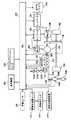
図1を参照して、本発明の実施の形態に係る制御装置が適用されるハイブリッド車両の制御ブロック図を説明する。 A control block diagram of a hybrid vehicle to which a control device according to an embodiment of the present invention is applied will be described with reference to FIG.
ハイブリッド車両は、駆動源として、リーンバーンガソリンエンジンやディーゼルエンジン等のNOx浄化が必要な内燃機関(以下、単にエンジンという)120と、回転電機である、モータジェネレータ(以下、単にMGという)(1)140Aと、MG(2)140Bとを含む。本実施の形態において、エンジン120は、リーンバーンガソリンエンジンであるとして説明する。 The hybrid vehicle has, as a drive source, an internal combustion engine (hereinafter simply referred to as an engine) 120 that requires NOx purification, such as a lean burn gasoline engine or a diesel engine, and a motor generator (hereinafter simply referred to as MG) (1) ) 140A and MG (2) 140B. In the present embodiment,
なお、本実施の形態においては、本発明をハイブリッド車両に適用する場合を一例として説明するが、本発明は、特にハイブリッド車両に限定して適用されるものではなく、たとえば、エンジンと無段変速機とが搭載される車両に適用するようにしてもよい。 In the present embodiment, a case where the present invention is applied to a hybrid vehicle will be described as an example. However, the present invention is not particularly limited to a hybrid vehicle. For example, an engine and a continuously variable transmission are used. You may make it apply to the vehicle by which a machine is mounted.
エンジン120の吸気通路122には、吸入空気のほこりを捕捉するエアクリーナ122A、エアクリーナ122Aを通ってエンジン120に吸入される空気量を検知するエアフローメータ122B、エンジン120に吸入される空気量を調整するためのバルブである電子スロットルバルブ122Cが設けられている。電子スロットルバルブ122Cにはスロットルポジションセンサ122Dが設けられている。ECU(Electronic Control Unit)320には、エアフローメータ122Bにより検出された吸入空気量や、スロットルポジションセンサ122Dにより検出された電子スロットルバルブ122Cの開度等が入力される。 In the
エンジン120には、複数の気筒および各気筒に燃料を噴射する燃料噴射装置130が設けられる。燃料噴射装置130は、ECU320からの燃料噴射制御信号に基づいて各気筒に対して適切な時期に適切な量の燃料を噴射する。
また、エンジン120の排気通路124には、三元触媒コンバータ124Bと、三元触媒コンバータ124Bに導入される排気における空燃比(A/F)を検出する空燃比センサ124Aと、三元触媒コンバータ124Bの温度を検出する触媒温度センサ124Cと、消音器124Dとが設けられている。ECU320には、空燃比センサ124Aにより検出された三元触媒コンバータ124Bに導入される排気の空燃比や、触媒温度センサ124Cにより検出された三元触媒コンバータ124Bの温度等が入力される。 Further, in the
なお、空燃比センサ124Aは、エンジン120で燃焼された混合気の空燃比に比例した出力電圧を発生する全域空燃比センサ(リニア空燃比センサ)である。本実施の形態において、空燃比センサ124Aは、検出素子を有し、エンジン120の排出ガスの検出素子への接触によりエンジン120の空燃比に対応した信号を出力する。なお、空燃比センサ124Aとしては、エンジン120で燃焼された混合気の空燃比が理論空燃比に対してリッチであるかリーンであるかをオン−オフ的に検出するO2センサを用いてもよい。 Air-
また、ECU320には、エンジン120の冷却水の温度を検出する水温検知センサ360からエンジン冷却水温を示す信号が入力される。エンジン120の出力軸には、クランクポジションセンサ380が設けられており、ECU320には、クランクポジションセンサ380から出力軸の回転数を示す信号が入力される。
ハイブリッド車両には、この他に、エンジン120やMG(2)140Bで発生した動力を駆動輪160に伝達したり、駆動輪160の駆動をエンジン120やMG(2)140Bに伝達する減速機180と、エンジン120の発生する動力を駆動輪160とMG(1)140Aとの2経路に分配する動力分割機構(たとえば、遊星歯車機構)200と、MG81)140AおよびMG(2)140B0を駆動するための電力を充電する走行用バッテリ220と、走行用バッテリ220の直流とMG(1)140AおよびMG(2)140Bの交流とを変換しながら電流制御を行なうインバータ240等を含む。 In addition to this, the hybrid vehicle transmits a power generated by the
ECU320は、走行用バッテリ220の充放電状態を管理制御したり、エンジン120の動作状態を制御したり、ハイブリッド車両の状態に応じてMG(1)140A、MG(2)140Bおよびインバータ240等を制御したり、後述する尿素水噴射装置314を制御したりする。
なお、本実施の形態においては、走行用バッテリ220の充電制御、エンジン120の制御、MG(1)140AおよびMG(2)140Bの制御および尿素水噴射装置314の制御を統合したECU320が実行するとして説明するが、特にこのような形態に限定されるものではない。たとえば、車両には、走行用バッテリ220の充放電状態を管理制御するバッテリECUと、エンジン120の動作状態を制御するエンジンECUと、尿素水噴射装置314の尿素水の噴射量を制御する触媒ECUと、ハイブリッド車両の状態に応じてMG(1)140A、MG(2)140B、バッテリECUおよびインバータ240等を制御するMG_ECUとがさらに設けられるものとし、ECU320が、バッテリECU、エンジンECU、触媒ECUおよびMG_ECU等を相互に管理制御して、ハイブリッド車両が最も効率よく運行できるようにハイブリッドシステム全体を制御するようにしてもよい。なお、走行用バッテリではなくキャパシタ等の蓄電機構であってもよい。 In the present embodiment,
本実施の形態においては、走行用バッテリ220とインバータ240との間にはコンバータ242が設けられている。これは、走行用バッテリ220の定格電圧が、MG(1)140AやMG(2)140Bの定格電圧よりも低いので、走行用バッテリ220からMG(1)140AやMG(2)140Bに電力を供給するときには、コンバータ242で電力を昇圧する。このコンバータ242には平滑コンデンサが内蔵されており、コンバータ242が昇圧動作を行なう際には、この平滑コンデンサに電荷が蓄えられる。 In the present embodiment,
運転席にはアクセルペダル(図示せず)が設けられており、アクセルポジションセンサ318は、アクセルペダルの踏込み量を検出する。アクセルポジションセンサ318は、アクセルペダルの踏込み量を示す信号をECU320に出力する。ECU320は、踏込み量に対応する要求駆動力に応じて、MG(1)140A、MG(2)140Bおよびエンジン120の出力あるいは発電量を制御する。 The driver's seat is provided with an accelerator pedal (not shown), and the
さらに、車速センサ330は、車両の速度に関連した物理量を検出するセンサである。「車両の速度に関連した物理量」とは、たとえば、車輪軸の回転数であってもよいし、トランスミッションの出力軸の回転数であってもよい。車速センサ330は、検出した物理量をECU320に送信する。 Furthermore, the
動力分割機構200は、エンジン120の動力を、駆動輪160とMG(1)140Aとの両方に振り分けるために、遊星歯車機構(プラネタリーギヤ)が使用される。MG(1)140Aの回転数を制御することにより、動力分割機構200は無段変速機としても機能する。 The
図1に示すようなハイブリッドシステムを搭載するハイブリッド車両においては、発進時や低速走行時等であってエンジン120の効率が悪い場合には、MG(2)140Bのみによりハイブリッド車両の走行を行ない、通常走行時には、たとえば動力分割機構200によりエンジン120の動力を2経路に分け、一方で駆動輪160の直接駆動を行ない、他方でMG(1)140Aを駆動して発電を行なう。この時、発生する電力でMG(2)140Bを駆動して駆動輪160の駆動補助を行なう。また、高速走行時には、さらに走行用バッテリ220からの電力をMG(2)140Bに供給してMG(2)140Bの出力を増大させて駆動輪160に対して駆動力の追加を行なう。 In a hybrid vehicle equipped with a hybrid system as shown in FIG. 1, when the
一方、減速時には、駆動輪160により従動するMG(2)140Bがジェネレータとして機能して回生発電を行ない、回収した電力を走行用バッテリ220に蓄える。なお、走行用バッテリ220の充電量が低下し、充電が特に必要な場合には、エンジン120の出力を増加してMG(1)140Aによる発電量を増やして走行用バッテリ220に対する充電量を増加する。もちろん、低速走行時でも必要に応じてエンジン120の駆動力を増加する制御を行なう場合もある。たとえば、上述のように走行用バッテリ220の充電が必要な場合や、エアコン等の補機を駆動する場合や、エンジン120の冷却水の温度を所定温度まで上げる場合等である。 On the other hand, at the time of deceleration, MG (2) 140B driven by
さらに、図1に示すようなハイブリッドシステムを搭載するハイブリッド車両においては、車両の運転状態や走行用バッテリ220の状態によっては、燃費を向上させるために、エンジン120を停止させる。そして、その後も車両の運転状態や走行用バッテリ220の状態を検出して、エンジン120を再始動させる。このように、このエンジン120は間欠運転され、従来の車両(エンジンしか搭載していない車両)においては、イグニッションスイッチがSTART位置にまで回されてエンジンが始動すると、イグニッションスイッチがON位置からACC位置またはOFF位置にされるまでエンジンが停止しない点で異なる。 Furthermore, in a hybrid vehicle equipped with a hybrid system as shown in FIG. 1,
尿素水噴射装置314は、三元触媒コンバータ124Bよりも上流の排気通路124内に尿素水を噴射する。尿素水噴射装置314は、たとえば、噴射ノズルとポンプとを含む。尿素水噴射装置314には、尿素水を蓄積する蓄積部である尿素水タンク316が接続される。尿素水噴射装置314は、たとえば、ECU320の噴射制御信号に応じて尿素水タンク316からポンプにより吸い上げた尿素水を噴射ノズルから排気通路124内に予め定められた量だけあるいは予め定められた時間が経過するまで噴射する。なお、排気通路124内にNOxを還元する還元剤を噴射できればよく、特に尿素水に限定されるものではない。また、ECU320は、NOx濃度センサ(図示せず)から検出されるNOx濃度に基づいて尿素水が排気通路124内に噴射されるように尿素水噴射装置314を制御するようにしてもよいし、エンジン120の動作点がNOx濃度が増加する領域であるときに尿素水が排気通路124内に噴射されるように尿素水噴射装置314を制御するようにしてもよい。 The urea
尿素水液量センサ312は、尿素水タンク316の尿素水の蓄積量を検出する。具体的には、尿素水液量センサ312は、尿素水の液面の位置を検出することにより尿素水の蓄積量を検出する。尿素水液量センサ312は、検出された蓄積量を示す信号をECU320に送信する。 The urea water
表示装置340は、尿素水タンク316に蓄積された尿素水の蓄積量を運転者に通知する。具体的には、表示装置340は、運転席周辺に設けられ、尿素水タンク316の液量の度合に対応する表示を行なう。 The
図2に示すように、表示装置340は、液量表示部342と、燃費表示部344とを含む。液量表示部342は、たとえば、4つの矩形の点灯領域が図2の紙面上下方向に互いに隣接するように配列されて構成される。4つの点灯領域は、図2の紙面下側から「0%」、「10%」、「15%」および「FULL」にそれぞれ対応する。なお、「0%」は、尿素水の液量が最大蓄積量に対して「0%以上」の量であることを示すものとする。また、「10%」は、尿素水の液量が最大蓄積量に対して「10%以上」の量であることを示すものとする。さらに、「15%」は、尿素水の液量が最大蓄積量に対して「15%以上」の量であることを示すものとする。さらに、「FULL」は、尿素水の液量が最大蓄積量であることを示すものとする。液量表示部342は、液量に対応した点灯領域が点灯し、対応しない点灯領域が消灯されることにより液量を表示する。 As shown in FIG. 2, the
図2においては、「0%」に対応する点灯領域と「10%」に対応する点灯領域とが点灯している状態を示す。この場合、液量は、「0%以上」であって、「10%以上」であって、かつ「15%以上」ではないことが表示されていることとなる。すなわち、図2の点灯の態様により運転者に対して液量が0%以上15%未満であることが通知されていることとなる。なお、液量表示部342の点灯領域は、特に矩形形状であることに限定されるものではなく、さらに、点灯領域の数も4つに限定されるものではない。液量表示部342の点灯領域は、たとえば、LED(Light Emitting Diode)により点灯するようにしてもよいし、LCD(Liquid Crystal Display)において表示されるようにしてもよい。液量表示部342は、ECU320からの液量表示制御信号に基づいて各点灯領域が点灯したり消灯したりする。 FIG. 2 shows a state in which the lighting area corresponding to “0%” and the lighting area corresponding to “10%” are lit. In this case, it is displayed that the liquid amount is “0% or more”, “10% or more”, and not “15% or more”. That is, the driver is notified that the liquid amount is 0% or more and less than 15% by the lighting mode of FIG. The lighting area of the liquid
また、本実施の形態において、液量の表示として、「0%以上」、「10%以上」、「15%以上」および「FULL」を表示するとして説明したが、少なくとも液量の有無を運転者に通知できればよく、これらの値に限定して表示されるものではない。 Further, in the present embodiment, it has been described that “0% or more”, “10% or more”, “15% or more”, and “FULL” are displayed as the liquid amount display. It is only necessary to be able to notify the person, and the display is not limited to these values.
燃費表示部344は、たとえば、4つの矩形の点灯領域が図2の紙面上下方向に互いに隣接するように配列されて構成される。4つの点灯領域のうち図2の紙面上下方向の上方の端部が「通常」、下方の端部が「悪化」にそれぞれ対応する。燃費表示部344は、燃費の状態に対応した点灯領域が点灯し、対応しない点灯領域が消灯されることにより燃費の悪化の度合が4段階で表示される。本実施の形態においては、燃費が通常である場合には、すべての点灯領域が点灯し、燃費が悪化する毎に悪化の度合に応じて「通常」側の点灯領域から消灯していくものとするが、4つの点灯領域のうち燃費の悪化の度合に対応するいずれか1つの点灯領域のみが点灯するようにしてもよい。 The fuel
図2においては、図2の下方の2つの点灯領域が点灯している状態を示す。この場合、通常のレベルよりも2段階低い燃費の悪化の度合が表示される。なお、燃費表示部344の点灯領域は、矩形形状であることに限定されるものではなく、さらに、点灯領域の数も4つに限定されるものではない。燃費表示部344の点灯領域は、たとえば、LED(Light Emitting Diode)により点灯するようにしてもよいし、LCD(Liquid Crystal Display)において表示されるようにしてもよい。燃費表示部344は、ECU320からの燃費表示制御信号に基づいて各点灯領域が点灯したり消灯したりする。 FIG. 2 shows a state in which the two lighting areas in the lower part of FIG. 2 are lit. In this case, the degree of deterioration in fuel consumption that is two steps lower than the normal level is displayed. In addition, the lighting area of the fuel
以上のような構成を有する車両において、本発明は、ECU320が、検出された尿素水の蓄積量の低下に応じてエンジン120の動作線を、NOxの発生の度合の小さい動作線に段階的に変更して、変更された動作線に基づいてエンジン120の出力を制御する点に特徴を有する。蓄積量の低下に応じて変更される動作線は、変更前の動作線と比較してエンジン120の回転数に対するトルクの発生の度合が低い動作線である。 In the vehicle having the above-described configuration, according to the present invention, the
図3に、本実施の形態に係る車両の制御装置であるECU320の機能ブロック図を示す。 FIG. 3 shows a functional block diagram of
ECU320は、入力インターフェース(以下、入力I/Fと記載する)300と、演算処理部400と、記憶部500と、出力インターフェース(以下、出力I/Fと記載する)600とを含む。
入力I/F300は、スロットルポジションセンサ122Dからのスロットルポジション信号と、尿素水液量センサ312からの液量検出信号と、アクセルポジションセンサ318からのアクセルポジション信号と、車速センサ330からの車速信号とを受信して、演算処理部400に送信する。 The input I /
演算処理部400は、液量判定部402と、動作線設定部404と、エンジン制御部406と、MG制御部408と、噴射量算出部410と、燃費算出部412と、表示制御部414とを含む。 The
液量判定部402は、液量検出信号に基づいて、液量が15%以上であるか否かを判定する。液量判定部402は、液量が15%以上でないと、液量が10%以上であるか否かを判定する。 The liquid
具体的には、液量判定部402は、検出された液量が蓄積部における最大蓄積量の15%に対応する蓄積量以上であるか否かを判定し、15%に対応する蓄積量以上でないと10%に対応する蓄積量以上であるか否かを判定する。なお、液量判定部402は、たとえば、検出された液量が15%に対応する蓄積量以上であるとFULL−15%判定フラグをオンし、10%に対応する蓄積量以上であると10%判定フラグをオンし、10%に対応する蓄積量以上でないと0%判定フラグをオンするようにしてもよい。 Specifically, the liquid
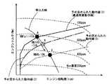
動作線設定部404は、検出された液量が低下するほどNOxの発生の度合の小さい動作線を設定する。たとえば、図4に示す、予め定められた動作線(1)〜(3)が記憶部500に予め記憶される。動作線設定部404は、検出された液量に対応した動作線を記憶部500から読み出す。 The operation
図4の実線に示す予め定められた動作線(1)は、最適燃費動作線を示し、液量が15%以上であるときのエンジン120の動作線に対応する。図4の一点鎖線に示す予め定められた動作線(2)は、液量が10%以上15%未満であるときのエンジン120の動作線に対応する。さらに、図4の破線に示す予め定められた動作線(3)は、液量が0%以上10%未満であるときのエンジン120の動作線に対応する。なお、動作線の数は3つに限定されるものではなく4以上の動作線を用いてもよい。 A predetermined operation line (1) indicated by a solid line in FIG. 4 indicates an optimum fuel consumption operation line, and corresponds to the operation line of the
予め定められた動作線(1)〜(3)は、実験等により適合されればよく、特に、予め定められた動作線(3)は、液量が0%になった場合に適切な排気浄化性能が発現するように設定される。たとえば、予め定められた動作線(3)は、最適燃費線と比較して、エンジン120の回転数に対するトルクの発生の度合が小さくなるように設定される。これにより、予め定められた動作線(1)よりもエンジン120の全回転域においてNOx濃度の増加を抑制することができる。予め定められた動作線(2)は、予め定められた動作線(1)と予め定められた動作線(3)との間になるように設定される。 The predetermined operation lines (1) to (3) may be adapted by experiments or the like. In particular, the predetermined operation line (3) is suitable for exhausting when the liquid amount becomes 0%. It is set so that the purification performance is expressed. For example, the predetermined operation line (3) is set so that the degree of torque generation with respect to the rotational speed of the
すなわち、予め定められた動作線(2)は、予め定められた動作線(1)よりもエンジン120の回転数に対するトルクの発生の度合が小さくなるように設定され、かつ、予め定められた動作線(3)よりもエンジン120の回転数にトルクの発生の度合が大きくなるように設定される。 In other words, the predetermined operation line (2) is set so that the degree of torque generation with respect to the rotational speed of the
動作線設定部404は、検出された液量に基づいて予め定められた動作線(1)〜(3)のうちのいずれかの動作線を記憶部500から読み出して設定する。なお、動作線設定部404は、たとえば、FULL−15%判定フラグがオンされていると、予め定められた動作線(1)を読み出して設定するようにしてもよいし、10%判定フラグがオンされていると、予め定められた動作線(2)を読み出して設定するようにしてもよいし、0%判定フラグがオンされていると、予め定められた動作線(3)を読み出して設定するようにしてもよい。 The operation
エンジン制御部406は、設定された動作線に基づいて、エンジン120を制御する。具体的には、アクセルポジションおよび車速に基づいて車両に要求される駆動力が特定される。エンジン制御部406は、特定された駆動力および設定された動作線に基づいて、動作線上の動作点を特定して、特定された動作点に対応する作動状態になるようにエンジン120を制御する。たとえば、エンジン制御部406は、エンジン120のスロットルポジション、燃料噴射量および点火時期等を制御して、特定された動作点に対応する作動状態になるようにエンジン120を制御する。 The
なお、エンジン制御部406は、設定された動作線が変更された場合においては、変更前の動作線上の動作点から変更後の動作線上に、等出力線に沿って移動した動作点に対応する作動状態になるようにエンジン120を制御する。 In addition, when the set operation line is changed, the
MG制御部408は、エンジン120の制御に並行して、MG(1)140AおよびMG(2)140Bを制御する。
具体的には、MG制御部408は、特定された駆動力に基づいて、エンジン120による発電の度合(すなわち、エンジン120から車輪に伝達される駆動力の度合)を設定し、設定された度合に対応した作動状態なるようにMG(1)140Aを制御する。 Specifically, the
さらに、MG制御部408は、特定された駆動力に基づいて、MG(2)140Bから車輪に伝達される駆動力の度合を設定し、設定された度合に対応した作動状態になるようにMG(2)140Bを制御する。 Further, the
エンジン120、MG(1)140AおよびMG(2)140Bの作動により車両には要求される駆動力が発現する。 The driving force required for the vehicle is developed by the operation of
噴射量算出部410は、エンジン120が予め定められた回転数だけ回転する毎の燃料噴射量を算出する。噴射量算出部410は、たとえば、エンジン120が予め定められた回転数だけ回転する期間の噴射時間の積算値に基づいて噴射量を算出するようにしてもよい。 The injection
燃費算出部412は、燃費の悪化の度合を算出する。燃費算出部412は、たとえば、エンジン120が予め定められた回転数だけ回転する毎の車両の走行距離と燃料噴射量とに基づいて瞬間燃費を算出する。燃費算出部412は、直前の予め定められた走行期間(距離または時間)の瞬間燃費の平均値と過去の平均値との偏差に応じて燃費の悪化の度合を算出する。あるいは、燃費算出部412は、直前の予め定められた走行期間における平均燃費と過去の平均燃費との偏差に応じて燃費の悪化の度合を算出するようにしてもよい。 The fuel
表示制御部414は、判定された液量に基づいて、液量表示部342に対応する表示制御信号を生成して、出力I/F600を経由して表示装置340に送信する。液量表示部342に対応する表示制御信号は、たとえば、液量表示部342の4つの点灯領域のうちのいずれの領域を点灯するかを示す信号である。 The
さらに、表示制御部414は、算出された燃費の悪化の度合に基づいて、燃費表示部344に対応する表示制御信号を生成して、出力I/F600を経由して表示装置340に送信する。燃費表示部344に対応する表示制御信号は、たとえば、燃費表示部344の4つの点灯領域のうちのいずれの領域を点灯するかを示す信号である。 Further, the
また、本実施の形態において、液量判定部402と、動作線設定部404と、エンジン制御部406と、MG制御部408と、噴射量算出部410と、燃費算出部412と、表示制御部414とは、いずれも演算処理部400であるCPU(Central Processing Unit)が記憶部500に記憶されたプログラムを実行することにより実現される、ソフトウェアとして機能するものとして説明するが、ハードウェアにより実現されるようにしてもよい。なお、このようなプログラムは記憶媒体に記録されて車両に搭載される。 In the present embodiment, the liquid
記憶部500には、各種情報、プログラム、しきい値、マップ等が記憶され、必要に応じて演算処理部400からデータが読み出されたり、格納されたりする。 Various information, programs, threshold values, maps, and the like are stored in the
以下、図5を参照して、本実施の形態に係る車両の制御装置であるECU320で実行されるプログラムの制御構造について説明する。 Hereinafter, with reference to FIG. 5, a control structure of a program executed by
ステップ(以下、ステップをSと記載する)100にて、ECU320は、尿素水の液量を検出する。 In step (hereinafter, step is referred to as S) 100,
S102にて、ECU320は、検出された尿素水の液量が15%以上であるか否かを判定する。検出された尿素水の液量が15%以上であると(S102にてYES)、処理はS104に移される。もしそうでないと(S102にてNO)、S106に移される。S104にて、ECU320は、予め定められた動作線(1)をエンジン120の動作線として設定する。 In S102,
S106にて、ECU320は、検出された尿素水の液量が10%以上であるか否かを判定する。尿素水の液量が10%以上であると(S106にてYES)、処理はS108に移される。もしそうでないと(S106にてNO)、処理はS110に移される。S108にて、ECU320は、予め定められた動作線(2)をエンジン120の動作線として設定する。 In S106,
S110にて、ECU320は、予め定められた動作線(3)をエンジン120の動作線として設定する。S112にて、ECU320は、車両の走行状態(アクセルポジションおよび車速)および設定された動作線に基づいてエンジン120の出力を制御する。S114にて、ECU320は、車両の走行状態に基づいて、MG(1)140AおよびMG(2)140Bの出力を制御する。 In S110,
S116にて、ECU320は、燃料の噴射量を算出する。S118にて、ECU320は、燃費の悪化の度合を算出する。S120にて、ECU320は、尿素水の液量と燃費の悪化の度合とを液量表示部342および燃費表示部344にそれぞれ表示するように表示装置340を制御する。 In S116,
以上のような構造およびフローチャートに基づく、本実施の形態に係る車両の制御装置であるECU320の動作について図6を用いて説明する。 The operation of
たとえば、尿素水の液量が15%以上である場合を想定する。尿素水の液量が15%以上であると(S102にてYES)、図6の実線に示す予め定められた動作線(1)がエンジン120の動作線として設定される(S104)。そのため、エンジン120は、予め定められた動作線(1)に沿って作動するように制御される(S112)。エンジン120の制御とともにMG(1)140AおよびMG(2)140Bが制御される(S114)。さらに、燃料の噴射量が算出され(S116)、燃費の悪化の度合が算出され(S118)、液量と燃費の悪化の度合とが表示装置340の液量表示部342および燃費表示部344にそれぞれ表示される(S120)。エンジン120は、最適燃費動作線に沿って作動するため、燃費表示部344においては、4つの点灯領域がすべて点灯することとなる。 For example, it is assumed that the amount of urea water is 15% or more. If the amount of urea water is 15% or more (YES in S102), a predetermined operation line (1) shown by the solid line in FIG. 6 is set as the operation line of engine 120 (S104). Therefore,
車両の走行に応じて尿素水の噴射が繰返されて、尿素水の液量が15%以上でなく(S102にてNO)、10%以上であると(S106にてYES)、図6の一点鎖線に示す予め定められた動作線(2)がエンジン120の動作線として設定される(S108)。そのため、エンジン120は、予め定められた動作線(2)に沿って制御される(S112)。 When the urea water injection is repeated according to the running of the vehicle, and the amount of urea water is not 15% or more (NO in S102) and 10% or more (YES in S106), one point in FIG. A predetermined operation line (2) indicated by a chain line is set as an operation line of the engine 120 (S108). Therefore,
このとき、たとえば、予め定められた動作線(1)に沿ってエンジン120が制御されるとした場合に動作点が図6のA点とされるとき、予め定められた動作線(2)が設定されると図6のB点を動作点としてエンジン120が制御される。このとき、A点とB点とは等出力線上の動作点の関係である。 At this time, for example, when the
エンジン120の制御とともにMG(1)140AおよびMG(2)140Bの出力が制御される(S114)。さらに、燃料の噴射量が算出され(S116)、燃費の悪化の度合が算出され(S118)、尿素水の液量と燃費の悪化の度合とが表示装置340の液量表示部342および燃費表示部344にそれぞれ表示される(S120)。 Along with the control of
予め定められた動作線(2)は、予め定められた動作線(1)よりもNOx濃度が低下する側に設定された動作線であるため、排気浄化性能の悪化が抑制されることとなる。なお、予め定められた動作線(2)は、最適燃費動作線から外れた動作線であるため、最適燃費動作線上でエンジン120を動作させる場合と比較して燃費が悪化する傾向にある。そのため、燃費表示部344においては、通常よりも悪化側の点灯領域のみが点灯する。これにより、運転者に対して液量の低下とともに燃費の悪化とが通知される。 Since the predetermined operation line (2) is an operation line set on the side where the NOx concentration is lower than the predetermined operation line (1), the deterioration of the exhaust purification performance is suppressed. . Since the predetermined operation line (2) is an operation line deviating from the optimum fuel consumption operation line, the fuel consumption tends to deteriorate as compared with the case where the
さらに、尿素水の噴射が繰返されて、尿素水の液量が15%以上でも、10%以上でもなくなると(S102にてNO,S106にてNO)、図6の点線に示す予め定められた動作線(3)がエンジン120の動作線として設定される(S110)。そのため、エンジン120は、予め定められた動作線(3)に沿って制御される(S112)。 Further, when the urea water injection is repeated and the amount of the urea water does not exceed 15% or 10% (NO in S102, NO in S106), it is determined in advance as indicated by a dotted line in FIG. The operation line (3) is set as the operation line of the engine 120 (S110). Therefore,
このとき、たとえば、予め定められた動作線(1)に沿ってエンジン120が制御されるとした場合に動作点が図6のA点とされるとき、予め定められた動作線(3)が設定されると図6のC点を動作点としてエンジン120が制御される。このとき、A点とC点と(加えて、B点と)は等出力線上の動作点の関係である。 At this time, for example, when
エンジン120の制御とともにMG(1)140AおよびMG(2)140Bの出力が制御される(S114)。さらに、燃料の噴射量が算出され(S116)、燃費の悪化の度合が算出され(S118)、尿素水の液量と燃費の悪化の度合とが表示装置340の液量表示部342および燃費表示部344にそれぞれ表示される(S120)。 Along with the control of
予め定められた動作線(3)は、予め定められた動作線(1)および(2)よりもNOx濃度が低下する側に設定された動作線であるため、排気浄化性能の悪化がさらに抑制されることとなる。なお、予め定められた動作線(3)は、最適燃費動作線から外れた動作線であるため、最適燃費線上でエンジン120を動作させる場合と比較して燃費が悪化する傾向にある。これにより、運転者に対して液量の低下とともに燃費の悪化とが通知される。 Since the predetermined operation line (3) is an operation line set on the side where the NOx concentration is lower than the predetermined operation lines (1) and (2), the deterioration of the exhaust purification performance is further suppressed. Will be. Since the predetermined operation line (3) is an operation line deviating from the optimum fuel consumption operation line, the fuel consumption tends to deteriorate as compared with the case where the
以上のようにして、本実施の形態に係る車両の制御装置によると、尿素水の液量の低下に応じてエンジンの動作線を、NOx濃度が低下する側の動作線に段階的に変更することにより、尿素水が無くなった場合に、運転者が急に車両の挙動が正常でない状態になることを感じることが抑制される。また、エンジンの動作線がNOxの発生の度合の小さい動作線に変更されるため、NOx濃度の増加を抑制することができる。そのため、排気ガス中のNOxの濃度の増加を抑制することができる。さらに、変更前の動作線上の動作点から変更された動作線に対して等出力線上で変更するようにすると、エンジンの出力を制限することなく、車両の走行を継続することができる。したがって、還元剤の蓄積が無くなった場合に内燃機関の排出ガス中の窒素酸化物の増加を抑制しつつ、運転者の意図に対応した性能を発現する車両の制御装置、制御方法およびその方法をコンピュータに実行させるプログラムならびにそのプログラムを記録した記録媒体を提供することができる。As described above, according to the vehicle control apparatus of the present embodiment, the engine operating line is gradually changed to the operating line on the side where the NOx concentration decreases in accordance with the decrease in the amount of urea water. This suppresses the driver from feeling that the behavior of the vehicle suddenly becomes abnormal when the urea water is exhausted. In addition, since the engine operating line is changed to an operating line with a low degree of NOx generation, an increase in NOx concentration can be suppressed. Therefore, an increase in the concentration of NOx in the exhaust gas can be suppressed. Furthermore, if the operation line changed from the operation point on the operation line before the change is changed on the iso-output line, the vehicle can continue to travel without restricting the engine output. Therefore, there is provided a vehicle control device, control method, and method for expressing performance corresponding to a driver's intention while suppressing an increase innitrogen oxides in exhaust gas of an internal combustion engine when there is no accumulation of reducing agent. A program to beexecuted by a computer and a recording medium on which the program is recorded can be provided.
さらに、尿素水の液量の低下により動作線がNOx濃度の発生の度合が小さい動作線に変更されることによりエンジンは最適燃費動作線から外れて作動するためエンジンの燃費は悪化する。そのため、燃費の悪化の度合を運転者に通知することにより、運転者が通常
よりも燃費が悪化した状態であることを認識させることができる。すなわち、尿素水の補給を促進することができる。したがって、運転者に還元剤の有無を適切に通知する車両の制御装置、制御方法およびその方法をコンピュータに実行させるプログラムならびにそのプログラムを記録した記録媒体を提供することができる。Further, when the operation line is changed to an operation line with a small degree of occurrence of NOx concentration due to a decrease in the amount of urea water, the engine operates outside the optimum fuel consumption operation line, and the fuel consumption of the engine deteriorates. Therefore, by notifying the driver of the degree of fuel consumption deterioration, the driver can recognize that the fuel consumption is worse than usual. That is, replenishment of urea water can be promoted. Therefore, it is possible to provide a vehicle control device, a control method, a program for causing a computer toexecute the method, and a recording medium recording the program for appropriately notifying the driver of the presence or absence of a reducing agent.
また、還元剤の蓄積量の低下を運転者に通知することにより、運転者に還元剤の補給を促進することができる。したがって、運転者に還元剤の有無を適切に通知することができる。 In addition, by notifying the driver of a decrease in the amount of accumulated reducing agent, the driver can be promoted to supply the reducing agent. Therefore, it is possible to appropriately notify the driver of the presence or absence of the reducing agent.
今回開示された実施の形態はすべての点で例示であって制限的なものではないと考えられるべきである。本発明の範囲は上記した説明ではなくて特許請求の範囲によって示され、特許請求の範囲と均等の意味および範囲内でのすべての変更が含まれることが意図される。 The embodiment disclosed this time should be considered as illustrative in all points and not restrictive. The scope of the present invention is defined by the terms of the claims, rather than the description above, and is intended to include any modifications within the scope and meaning equivalent to the terms of the claims.
120 エンジン、122 吸気通路、122A エアクリーナ、122B エアフローメータ、122C 電子スロットルバルブ、122D スロットルポジションセンサ、124 排気通路、124A 空燃比センサ、124B 三元触媒コンバータ、124C 触媒温度センサ、124D 消音器、130 燃料噴射装置、140A,140B モータジェネレータ、160 駆動輪、180 減速機、200 動力分割機構、220 走行用バッテリ、240 インバータ、242 コンバータ、300 入力I/F、312 尿素水液量センサ、314 尿素水噴射装置、316 尿素水タンク、318 アクセルポジションセンサ、330 車速センサ、340 表示装置、342 液量表示部、344 燃費表示部、360 水温検知センサ、380 クランクポジションセンサ、400 演算処理部、402 液量判定部、404 動作線設定部、406 エンジン制御部、408 MG制御部、410 噴射量算出部、412 燃費算出部、414 表示制御部、460 エンジン制御部、500 記憶部、600 出力I/F。 120 engine, 122 intake passage, 122A air cleaner, 122B air flow meter, 122C electronic throttle valve, 122D throttle position sensor, 124 exhaust passage, 124A air-fuel ratio sensor, 124B three-way catalytic converter, 124C catalyst temperature sensor, 124D silencer, 130 fuel Injector, 140A, 140B Motor generator, 160 drive wheel, 180 reducer, 200 power split mechanism, 220 battery for traveling, 240 inverter, 242 converter, 300 input I / F, 312 urea water quantity sensor, 314 urea water injection Device, 316 urea water tank, 318 accelerator position sensor, 330 vehicle speed sensor, 340 display device, 342 fluid amount display unit, 344 fuel consumption display unit, 360 water temperature detection sensor, 38 DESCRIPTION OF
Claims (21)
Translated fromJapanese前記蓄積部における前記還元剤の蓄積量を検出するための検出手段と、
前記検出された蓄積量の低下に応じて前記内燃機関の動作線を、窒素酸化物の発生の度合の小さい動作線に段階的に変更して、前記変更された動作線に基づいて前記内燃機関の出力を制御するための制御手段とを含み、
前記制御手段は、前記動作線の変更に応じて等出力線に沿って動作点を変更して前記内燃機関の出力を制御する、車両の制御装置。A control device for a vehicle on which an internal combustion engine is mounted, the internal combustion engine including an exhaust passage, an injection device that injects a reducing agent into the exhaust passage, and an accumulation unit that accumulates the reducing agent,
Detection means for detecting the amount of accumulation of the reducing agent in the accumulation unit;
The operation line of the internal combustion engine is changed stepwise to an operation line with a small degree of generation of nitrogen oxides according to the detected decrease in the accumulated amount, and the internal combustion engine is changed based on the changed operation line.look including a control means for controlling the outputof,
The control unit is a vehicle control devicethat controls an output of the internal combustion engine by changing an operating point along an iso-output line according to the change of the operating line .
前記制御手段は、前記第1の動作線と前記第2の動作線と前記第3の動作線とのうちの前記検出された蓄積量に対応した動作線に変更する、請求項1または2に記載の車両の制御装置。The operation line of the internal combustion engine is set corresponding to a case where the accumulation amount of the reducing agent in the accumulation unit is equal to or greater than a predetermined amount, and is at least a first operation that is an optimum fuel consumption operation line of the internal combustion engine. A line, a second operation line set corresponding to a case where the accumulation amount of the reducing agent in the storage unit becomes zero, and a setting between the first operation line and the second operation line A third operating line to be
3. The control unit according to claim 1, wherein the control unit changes to an operation line corresponding to the detected accumulation amount among the first operation line, the second operation line, and the third operation line. The vehicle control device described.
前記車両の走行距離に関連する物理量を検出するための手段と、
前記内燃機関への燃料の噴射量を算出するための手段と、
前記検出された物理量と前記燃料の供給量とに基づいて前記内燃機関の燃費の悪化の度合を算出するための算出手段と、
前記算出された燃費の悪化の度合を運転者に通知するための燃費通知手段とをさらに含む、請求項1〜3のいずれかに記載の車両の制御装置。The controller is
Means for detecting a physical quantity related to a travel distance of the vehicle;
Means for calculating the amount of fuel injected into the internal combustion engine;
Calculation means for calculating the degree of deterioration of fuel consumption of the internal combustion engine based on the detected physical quantity and the fuel supply amount;
The vehicle control device accordingto any one of claims 1 to3 , further comprising fuel consumption notification means for notifying a driver of the calculated degree of deterioration of fuel consumption.
前記蓄積部における前記還元剤の蓄積量を検出する検出ステップと、
前記検出された蓄積量の低下に応じて前記内燃機関の動作線を、窒素酸化物の発生の度合の小さい動作線に段階的に変更して、前記変更された動作線に基づいて前記内燃機関の出力を制御する制御ステップとを含み、
前記制御ステップは、前記動作線の変更に応じて等出力線に沿って動作点を変更して前記内燃機関の出力を制御する、車両の制御方法。A control method for a vehicle in which an internal combustion engine is mounted, the internal combustion engine including an exhaust passage, an injection device that injects a reducing agent into the exhaust passage, and an accumulation unit that accumulates the reducing agent,
A detection step of detecting an amount of accumulation of the reducing agent in the accumulation unit;
The operation line of the internal combustion engine is changed stepwise to an operation line with a small degree of generation of nitrogen oxides according to the detected decrease in the accumulated amount, and the internal combustion engine is changed based on the changed operation line.look including a control step of controlling the outputof,
The control step is a vehicle control methodof controlling an output of the internal combustion engine by changing an operating point along an iso-output line according to the change of the operating line .
前記制御ステップは、前記第1の動作線と前記第2の動作線と前記第3の動作線とのうちの前記検出された蓄積量に対応した動作線に変更する、請求項10または11に記載の車両の制御方法。The operation line of the internal combustion engine is set corresponding to a case where the accumulation amount of the reducing agent in the accumulation unit is equal to or greater than a predetermined amount, and is at least a first operation that is an optimum fuel consumption operation line of the internal combustion engine. A line, a second operation line set corresponding to a case where the accumulation amount of the reducing agent in the storage unit becomes zero, and a setting between the first operation line and the second operation line A third operating line to be
The control step changes the operation line corresponding to the detected reserved amount among the first operation line and said second operation line and the third operation line,in claim10 or 11 The vehicle control method described.
前記車両の走行距離に関連する物理量を検出するステップと、
前記内燃機関への燃料の噴射量を算出するステップと、
前記検出された物理量と前記燃料の供給量とに基づいて前記内燃機関の燃費の悪化の度合を算出する算出ステップと、
前記算出された燃費の悪化の度合を運転者に通知する燃費通知ステップとをさらに含む、請求項10〜12のいずれかに記載の車両の制御方法。The control method is:
Detecting a physical quantity related to a travel distance of the vehicle;
Calculating the amount of fuel injected into the internal combustion engine;
A calculation step of calculating a degree of deterioration of fuel consumption of the internal combustion engine based on the detected physical quantity and the fuel supply amount;
The vehicle control method accordingto claim10 , further comprising a fuel consumption notification step of notifying a driver of the calculated degree of deterioration of fuel consumption.
前記内燃機関は、排気通路と、前記排気通路に配置され排気中の窒素酸化物を浄化する触媒と、前記触媒の上流より前記排気通路内へ還元剤を供給する還元剤供給装置と、前記還元剤を貯留する還元剤タンクと、を含み、前記車両は、前記内燃機関の出力を駆動軸にてドライバー要求に応じた状態とする駆動機構を含み、The internal combustion engine includes an exhaust passage, a catalyst that is disposed in the exhaust passage and purifies nitrogen oxides in the exhaust, a reducing agent supply device that supplies a reducing agent into the exhaust passage from upstream of the catalyst, and the reduction A reducing agent tank for storing an agent, and the vehicle includes a drive mechanism that causes the output of the internal combustion engine to be in a state according to a driver request on a drive shaft,
前記制御装置は、The control device includes:
前記還元剤タンクにおける前記還元剤の残量を検出または算出するための還元剤残量把握ユニットと、A reducing agent remaining amount grasping unit for detecting or calculating the remaining amount of the reducing agent in the reducing agent tank;
前記ドライバー要求により定まる前記内燃機関の動作点を、前記検出または算出された還元剤の残量に応じて、窒素酸化物の排出が少なくなる等出力線上の動作点に変更して、前記内燃機関の出力を制御する制御ユニットとを含む、車両の制御装置。The operating point of the internal combustion engine determined by the driver request is changed to an operating point on an iso-output line where nitrogen oxide emission is reduced according to the detected or calculated remaining amount of the reducing agent, And a control unit for controlling the output of the vehicle.
Priority Applications (5)
| Application Number | Priority Date | Filing Date | Title |
|---|---|---|---|
| JP2008057687AJP4329866B1 (en) | 2008-03-07 | 2008-03-07 | Vehicle control device, control method, program for causing computer to execute the method, and recording medium recording the program |
| PCT/JP2009/051547WO2009110269A1 (en) | 2008-03-07 | 2009-01-30 | Device and method for controlling vehicle |
| CN200980108063.6ACN101960129B (en) | 2008-03-07 | 2009-01-30 | Vehicle control device and control method |
| EP09717444.5AEP2249016B1 (en) | 2008-03-07 | 2009-01-30 | Control device and control method for vehicle |
| US12/810,269US8473178B2 (en) | 2008-03-07 | 2009-01-30 | Control device and control method for vehicle |
Applications Claiming Priority (1)
| Application Number | Priority Date | Filing Date | Title |
|---|---|---|---|
| JP2008057687AJP4329866B1 (en) | 2008-03-07 | 2008-03-07 | Vehicle control device, control method, program for causing computer to execute the method, and recording medium recording the program |
Publications (2)
| Publication Number | Publication Date |
|---|---|
| JP4329866B1true JP4329866B1 (en) | 2009-09-09 |
| JP2009215898A JP2009215898A (en) | 2009-09-24 |
Family
ID=41055831
Family Applications (1)
| Application Number | Title | Priority Date | Filing Date |
|---|---|---|---|
| JP2008057687AExpired - Fee RelatedJP4329866B1 (en) | 2008-03-07 | 2008-03-07 | Vehicle control device, control method, program for causing computer to execute the method, and recording medium recording the program |
Country Status (5)
| Country | Link |
|---|---|
| US (1) | US8473178B2 (en) |
| EP (1) | EP2249016B1 (en) |
| JP (1) | JP4329866B1 (en) |
| CN (1) | CN101960129B (en) |
| WO (1) | WO2009110269A1 (en) |
Cited By (1)
| Publication number | Priority date | Publication date | Assignee | Title |
|---|---|---|---|---|
| CN102892987A (en)* | 2010-05-17 | 2013-01-23 | 五十铃自动车株式会社 | Scr system |
Families Citing this family (21)
| Publication number | Priority date | Publication date | Assignee | Title |
|---|---|---|---|---|
| CN102356301B (en)* | 2009-03-18 | 2013-04-10 | 克朗设备公司 | Fuel level meter for industrial vehicles |
| JP5471831B2 (en) | 2010-05-25 | 2014-04-16 | いすゞ自動車株式会社 | SCR system |
| US9030063B2 (en) | 2010-12-17 | 2015-05-12 | Tesla Motors, Inc. | Thermal management system for use with an integrated motor assembly |
| DE102010056399A1 (en)* | 2010-12-28 | 2012-06-28 | GM Global Technology Operations LLC | Motor vehicle with an exhaust aftertreatment system and method for operating the motor vehicle |
| SE535932C2 (en)* | 2011-04-19 | 2013-02-26 | Scania Cv Ab | Method and apparatus for determining residual volume of reducing agent in a container of an SCR system |
| FR2979668B1 (en)* | 2011-09-01 | 2013-09-20 | Peugeot Citroen Automobiles Sa | METHOD OF THERMALLY PROTECTING A DEPOLLUTION MEMBER OF AN EXHAUST LINE AND CORRESPONDING VEHICLE |
| JP5862311B2 (en)* | 2012-01-11 | 2016-02-16 | トヨタ自動車株式会社 | Hybrid vehicle |
| JP5998506B2 (en)* | 2012-02-13 | 2016-09-28 | 株式会社デンソー | Control device for hybrid vehicle |
| DE102012204352B4 (en)* | 2012-03-01 | 2023-09-07 | Robert Bosch Gmbh | Method for operating a drive device |
| US9500114B2 (en) | 2014-02-18 | 2016-11-22 | Komatsu Ltd. | Work vehicle display device and work vehicle |
| KR101543162B1 (en)* | 2014-05-09 | 2015-08-07 | 현대자동차주식회사 | Urea Selective Catalytic Reduction System, Method and Controller using Touch Sense to Recognize Urea Selective Catalytic Reduction |
| US20160082949A1 (en)* | 2014-09-22 | 2016-03-24 | Hyundai Motor Company | System for improving exhaust gas purifying performance of diesel hybrid electric vehicle |
| US20170276530A1 (en)* | 2014-09-24 | 2017-09-28 | Hitachi Construction Machinery Co., Ltd. | Display apparatus for work machine |
| KR101673336B1 (en)* | 2015-04-02 | 2016-11-07 | 현대자동차 주식회사 | Method and system of driver inducement for vehicle |
| JP6358179B2 (en)* | 2015-07-16 | 2018-07-18 | トヨタ自動車株式会社 | Automatic vehicle driving system |
| JP6319241B2 (en)* | 2015-09-11 | 2018-05-09 | マツダ株式会社 | Automobile with generator drive engine |
| US10059325B2 (en)* | 2016-07-21 | 2018-08-28 | Ford Global Technologies, Llc | Method and system for controlling water injection |
| JP6423026B2 (en) | 2017-02-09 | 2018-11-14 | 本田技研工業株式会社 | Hybrid car |
| JP6828705B2 (en)* | 2018-03-12 | 2021-02-10 | トヨタ自動車株式会社 | Vehicle control device |
| US11377088B2 (en) | 2018-04-02 | 2022-07-05 | Cummins Inc. | Electric vehicles with engines and interaction with aftertreatment |
| JP7488228B2 (en)* | 2021-07-28 | 2024-05-21 | 矢崎総業株式会社 | Vehicle control unit and vehicle control system |
Family Cites Families (17)
| Publication number | Priority date | Publication date | Assignee | Title |
|---|---|---|---|---|
| DE19629163C1 (en)* | 1996-07-19 | 1997-10-09 | Daimler Benz Ag | Diesel engine operation to suppress nitrogen oxides emission |
| US6063350A (en) | 1997-04-02 | 2000-05-16 | Clean Diesel Technologies, Inc. | Reducing nox emissions from an engine by temperature-controlled urea injection for selective catalytic reduction |
| JP3854013B2 (en)* | 1999-06-10 | 2006-12-06 | 三菱電機株式会社 | Exhaust gas purification device for internal combustion engine |
| JP3613681B2 (en) | 2001-04-23 | 2005-01-26 | トヨタ自動車株式会社 | Control device for internal combustion engine |
| US6866610B2 (en)* | 2001-03-30 | 2005-03-15 | Toyota Jidosha Kabushiki Kaisha | Control apparatus and method for vehicle having internal combustion engine and continuously variable transmission, and control apparatus and method for internal combustion engine |
| JP2002371831A (en) | 2001-06-13 | 2002-12-26 | Nissan Diesel Motor Co Ltd | Exhaust emission control device of automobile |
| US6421599B1 (en)* | 2001-08-09 | 2002-07-16 | Ford Global Technologies, Inc. | Control strategy for an internal combustion engine in a hybrid vehicle |
| JP3718209B2 (en) | 2003-10-03 | 2005-11-24 | 日産ディーゼル工業株式会社 | Engine exhaust purification system |
| JP4326976B2 (en) | 2003-10-22 | 2009-09-09 | 日産ディーゼル工業株式会社 | Engine exhaust purification system |
| JP4158733B2 (en)* | 2004-03-29 | 2008-10-01 | 株式会社デンソー | Fuel injection device |
| JP4308094B2 (en) | 2004-06-23 | 2009-08-05 | 日野自動車株式会社 | Reducing agent supply device |
| JP2006170057A (en) | 2004-12-15 | 2006-06-29 | Toyota Motor Corp | Apparatus and method for controlling internal combustion engine of hybrid vehicle |
| JP4375248B2 (en) | 2005-02-17 | 2009-12-02 | 株式会社デンソー | Driving support device |
| JP4444165B2 (en)* | 2005-06-10 | 2010-03-31 | 日産ディーゼル工業株式会社 | Engine exhaust purification system |
| JP2006090334A (en)* | 2005-12-21 | 2006-04-06 | Nissan Diesel Motor Co Ltd | Exhaust emission purifier of engine |
| US7861518B2 (en)* | 2006-01-19 | 2011-01-04 | Cummins Inc. | System and method for NOx reduction optimization |
| JP4937617B2 (en) | 2006-03-24 | 2012-05-23 | 三菱ふそうトラック・バス株式会社 | Exhaust gas purification system for vehicle internal combustion engine |
- 2008
- 2008-03-07JPJP2008057687Apatent/JP4329866B1/ennot_activeExpired - Fee Related
- 2009
- 2009-01-30EPEP09717444.5Apatent/EP2249016B1/ennot_activeNot-in-force
- 2009-01-30CNCN200980108063.6Apatent/CN101960129B/ennot_activeExpired - Fee Related
- 2009-01-30USUS12/810,269patent/US8473178B2/ennot_activeExpired - Fee Related
- 2009-01-30WOPCT/JP2009/051547patent/WO2009110269A1/ennot_activeCeased
Cited By (2)
| Publication number | Priority date | Publication date | Assignee | Title |
|---|---|---|---|---|
| CN102892987A (en)* | 2010-05-17 | 2013-01-23 | 五十铃自动车株式会社 | Scr system |
| CN102892987B (en)* | 2010-05-17 | 2015-04-22 | 五十铃自动车株式会社 | selective catalytic reduction system |
Also Published As
| Publication number | Publication date |
|---|---|
| WO2009110269A1 (en) | 2009-09-11 |
| CN101960129A (en) | 2011-01-26 |
| CN101960129B (en) | 2014-01-08 |
| EP2249016B1 (en) | 2018-12-26 |
| EP2249016A1 (en) | 2010-11-10 |
| JP2009215898A (en) | 2009-09-24 |
| EP2249016A4 (en) | 2017-10-11 |
| US20100280740A1 (en) | 2010-11-04 |
| US8473178B2 (en) | 2013-06-25 |
Similar Documents
| Publication | Publication Date | Title |
|---|---|---|
| JP4329866B1 (en) | Vehicle control device, control method, program for causing computer to execute the method, and recording medium recording the program | |
| JP4911206B2 (en) | Vehicle control apparatus and control method | |
| CN103249622B (en) | Control device and control method both for hybrid vehicle, | |
| JP4513629B2 (en) | Vehicle control device | |
| US20110035136A1 (en) | Control device and control method for vehicle | |
| US20100063662A1 (en) | Control device and control method of hybrid vehicle | |
| CN108691621A (en) | The emission control system of hybrid electric vehicle | |
| JP5929699B2 (en) | Control device for hybrid vehicle | |
| JP5130162B2 (en) | Control device and control method for hybrid vehicle | |
| US20110276211A1 (en) | Control device for vehicle | |
| JP2005273530A (en) | Control device for internal combustion engine and automobile equipped with the same | |
| JP5267622B2 (en) | Power unit control unit | |
| JP2009092001A (en) | Control device for internal combustion engine, control method, program for realizing the method, and recording medium recording the program | |
| US11067025B2 (en) | Controller for vehicle and method for controlling vehicle | |
| JP2009100542A (en) | Rotating electrical machine control device, control method, program for realizing the method on a computer, and recording medium storing the program | |
| JP5239809B2 (en) | Vehicle control apparatus and control method | |
| JP4013654B2 (en) | Exhaust gas purification device for hybrid vehicle | |
| JP2011235809A (en) | Device and method for controlling vehicles | |
| JP5716652B2 (en) | Control device for hybrid vehicle | |
| JP5018162B2 (en) | VEHICLE CONTROL DEVICE, CONTROL METHOD, PROGRAM FOR MAKING THE METHOD TO COMPUTER COMPUTER, AND RECORDING MEDIUM CONTAINING THE PROGRAM | |
| JP4710473B2 (en) | Engine fuel injection control device | |
| JP2008120350A (en) | VEHICLE CONTROL DEVICE, CONTROL METHOD, PROGRAM USING THE METHOD BY COMPUTER AND RECORDING MEDIUM CONTAINING THE PROGRAM | |
| JP2006132506A (en) | Fuel injection control device for vehicle internal combustion engine | |
| JP2021109549A (en) | Vehicle control device | |
| JP2006299826A (en) | Control device for internal combustion engine |
Legal Events
| Date | Code | Title | Description |
|---|---|---|---|
| TRDD | Decision of grant or rejection written | ||
| A01 | Written decision to grant a patent or to grant a registration (utility model) | Free format text:JAPANESE INTERMEDIATE CODE: A01 Effective date:20090526 | |
| A01 | Written decision to grant a patent or to grant a registration (utility model) | Free format text:JAPANESE INTERMEDIATE CODE: A01 | |
| A61 | First payment of annual fees (during grant procedure) | Free format text:JAPANESE INTERMEDIATE CODE: A61 Effective date:20090608 | |
| R151 | Written notification of patent or utility model registration | Ref document number:4329866 Country of ref document:JP Free format text:JAPANESE INTERMEDIATE CODE: R151 | |
| FPAY | Renewal fee payment (event date is renewal date of database) | Free format text:PAYMENT UNTIL: 20120626 Year of fee payment:3 | |
| FPAY | Renewal fee payment (event date is renewal date of database) | Free format text:PAYMENT UNTIL: 20120626 Year of fee payment:3 | |
| FPAY | Renewal fee payment (event date is renewal date of database) | Free format text:PAYMENT UNTIL: 20130626 Year of fee payment:4 | |
| LAPS | Cancellation because of no payment of annual fees |