JP4328788B2 - Nucleic acid sample testing equipment - Google Patents
Nucleic acid sample testing equipmentDownload PDFInfo
- Publication number
- JP4328788B2 JP4328788B2JP2006213357AJP2006213357AJP4328788B2JP 4328788 B2JP4328788 B2JP 4328788B2JP 2006213357 AJP2006213357 AJP 2006213357AJP 2006213357 AJP2006213357 AJP 2006213357AJP 4328788 B2JP4328788 B2JP 4328788B2
- Authority
- JP
- Japan
- Prior art keywords
- reaction
- container
- reagent
- carrier
- unit
- Prior art date
- Legal status (The legal status is an assumption and is not a legal conclusion. Google has not performed a legal analysis and makes no representation as to the accuracy of the status listed.)
- Expired - Fee Related
Links
Images


Classifications
- G—PHYSICS
- G01—MEASURING; TESTING
- G01N—INVESTIGATING OR ANALYSING MATERIALS BY DETERMINING THEIR CHEMICAL OR PHYSICAL PROPERTIES
- G01N35/00—Automatic analysis not limited to methods or materials provided for in any single one of groups G01N1/00 - G01N33/00; Handling materials therefor
- G01N35/02—Automatic analysis not limited to methods or materials provided for in any single one of groups G01N1/00 - G01N33/00; Handling materials therefor using a plurality of sample containers moved by a conveyor system past one or more treatment or analysis stations
- G01N35/026—Automatic analysis not limited to methods or materials provided for in any single one of groups G01N1/00 - G01N33/00; Handling materials therefor using a plurality of sample containers moved by a conveyor system past one or more treatment or analysis stations having blocks or racks of reaction cells or cuvettes
- C—CHEMISTRY; METALLURGY
- C12—BIOCHEMISTRY; BEER; SPIRITS; WINE; VINEGAR; MICROBIOLOGY; ENZYMOLOGY; MUTATION OR GENETIC ENGINEERING
- C12Q—MEASURING OR TESTING PROCESSES INVOLVING ENZYMES, NUCLEIC ACIDS OR MICROORGANISMS; COMPOSITIONS OR TEST PAPERS THEREFOR; PROCESSES OF PREPARING SUCH COMPOSITIONS; CONDITION-RESPONSIVE CONTROL IN MICROBIOLOGICAL OR ENZYMOLOGICAL PROCESSES
- C12Q1/00—Measuring or testing processes involving enzymes, nucleic acids or microorganisms; Compositions therefor; Processes of preparing such compositions
- C12Q1/68—Measuring or testing processes involving enzymes, nucleic acids or microorganisms; Compositions therefor; Processes of preparing such compositions involving nucleic acids
- C12Q1/6813—Hybridisation assays
- C12Q1/6834—Enzymatic or biochemical coupling of nucleic acids to a solid phase
- C12Q1/6837—Enzymatic or biochemical coupling of nucleic acids to a solid phase using probe arrays or probe chips
- G—PHYSICS
- G01—MEASURING; TESTING
- G01N—INVESTIGATING OR ANALYSING MATERIALS BY DETERMINING THEIR CHEMICAL OR PHYSICAL PROPERTIES
- G01N35/00—Automatic analysis not limited to methods or materials provided for in any single one of groups G01N1/00 - G01N33/00; Handling materials therefor
- G01N35/00584—Control arrangements for automatic analysers
- G01N35/0092—Scheduling
- G01N2035/0093—Scheduling random access not determined by physical position
Landscapes
- Chemical & Material Sciences (AREA)
- Life Sciences & Earth Sciences (AREA)
- Health & Medical Sciences (AREA)
- General Health & Medical Sciences (AREA)
- Analytical Chemistry (AREA)
- Immunology (AREA)
- Physics & Mathematics (AREA)
- Biochemistry (AREA)
- Organic Chemistry (AREA)
- Pathology (AREA)
- General Physics & Mathematics (AREA)
- Chemical Kinetics & Catalysis (AREA)
- Zoology (AREA)
- Wood Science & Technology (AREA)
- Engineering & Computer Science (AREA)
- Proteomics, Peptides & Aminoacids (AREA)
- Biophysics (AREA)
- Molecular Biology (AREA)
- Bioinformatics & Cheminformatics (AREA)
- General Engineering & Computer Science (AREA)
- Microbiology (AREA)
- Genetics & Genomics (AREA)
- Biotechnology (AREA)
- Apparatus Associated With Microorganisms And Enzymes (AREA)
- Automatic Analysis And Handling Materials Therefor (AREA)
Description
Translated fromJapanese本発明は、核酸試料検査装置に係り、特に複数の工程を処理でき、容器を搬送するための搬送系を備えた核酸試料検査装置に関する。 The present invention relates to a nucleic acid sample testing apparatus, and more particularly to a nucleic acid sample testing apparatus that can process a plurality of steps and includes a transport system for transporting a container.
近年、DNAマイクロアレイ、DNAチップ等の試験片を用いた遺伝子解析が行われている。スライドガラスやシリコン基板などからなる基板表面に多数のDNAプローブをプローブスポットとしてマトリクス状に配置固定した検出体であるDNAチップと、蛍光色素などで標識付けられたDNAなどの核酸試料をハイブリダイゼーション条件下で接触させる。検出体(DNAチップ)及び試料に互いにハイブリダイゼーションする核酸同士が含まれていれば、検出体に標識物質(標識付けられた試料)がプローブ核酸を介して固定される。そして検出体上のどこに標識物質が存在するかを検出することにより、ハイブリダイズした核酸の種類を特定することができるものである。このハイブリダイゼーション反応を利用したDNAマイクロアレイは、病原菌を特定する医療診断や患者の体質等を検査する遺伝子診断への応用が期待されている。 In recent years, gene analysis using test pieces such as DNA microarrays and DNA chips has been performed. Hybridization conditions for DNA chips, which are detection bodies in which a large number of DNA probes are arranged and fixed as probe spots in a matrix on the surface of a glass slide or silicon substrate, and nucleic acid samples such as DNA labeled with fluorescent dyes Contact below. If nucleic acids that hybridize to each other are contained in the detection body (DNA chip) and the sample, the labeling substance (labeled sample) is immobilized on the detection body via the probe nucleic acid. The type of the hybridized nucleic acid can be specified by detecting where the labeling substance is present on the detection body. DNA microarrays utilizing this hybridization reaction are expected to be applied to medical diagnosis for identifying pathogenic bacteria and genetic diagnosis for examining patient constitutions.
一般的に核酸試料検査装置のような液体を用いて反応させるような装置においては、試薬や検体などの液体はピペットなどの分注装置を用いて反応容器に分注し、かつ反応容器は温度調節部などの反応エリアに配置させる必要がある。そこで試薬や反応容器を別々の搬送系で分注装置部や反応エリアへの移動をさせるような装置が提案されている(例えば特許文献1参照)。
核酸試料検査装置においては抽出、増幅、ハイブリダイゼーション、検出というような複数の工程を処理する必要があり、解析を迅速に、しかも多量に行うためには複数の工程を同時に並列処理する必要がある。また、工程が複数にわたるため、構成を簡略化して装置を小型化する必要がある。特許文献1に開示された装置においては、試薬と反応容器は異なる搬送系上に配置されているため、搬送系が2つ必要となっている。また、反応用の搬送系上には、反応部と検出部が配置されているが、この構成では反応と検出を並列で同時に処理することが不可能であるという問題がある。 Nucleic acid sample testing equipment must process multiple steps such as extraction, amplification, hybridization, and detection, and multiple processes must be processed in parallel to perform analysis quickly and in large quantities. . In addition, since there are a plurality of processes, it is necessary to simplify the configuration and downsize the apparatus. In the apparatus disclosed in Patent Document 1, since the reagent and the reaction container are arranged on different transport systems, two transport systems are required. Further, the reaction unit and the detection unit are arranged on the reaction transport system. However, this configuration has a problem that it is impossible to process the reaction and the detection simultaneously in parallel.
したがって、それぞれの工程ごとに試薬や反応容器を効率よく必要な位置に移動することができ、処理が終了すれば次の工程に移動でき、かつ小型であるような装置が求められていた。 Therefore, there has been a demand for an apparatus that can efficiently move a reagent and a reaction container to a necessary position for each process, and can move to the next process when the process is completed, and is small in size.
本発明は、上記従来技術の実状に鑑み、各工程に試薬や反応容器を効率よく必要な位置に移動させることができ、かつ小型である核酸試料検査装置を提供することを目的としている。 An object of the present invention is to provide a nucleic acid sample testing apparatus that can efficiently move a reagent or a reaction container to a necessary position in each process and is small in view of the actual state of the above-described conventional technology.
上記目的を達成するために、本発明の核酸試料検査装置の一つは、反応エリアと検出部とを互いに異なる位置に有する核酸試料検査装置であって、
1つ以上の試薬容器と、該試薬容器とは連結されていない1つ以上の反応容器とを載せて、前記反応エリアに搬送する第一搬送部と、
検体、検体の反応物、および試薬の少なくとも一つを前記試薬容器または前記反応容器に供給する手段と、
前記反応エリアで反応処理後、前記反応容器のみを前記検出部に搬送する手段と、
を備えたことを特徴とする。In order to achieve the above object,one of the nucleic acid sample testing devicesof the present invention is a nucleic acid sample testing device having areaction area and a detection unit at different positions,
One or more reagent containers and the reagent containers loaded with one or more reaction vessels that are not connected,a first conveying section for conveying tothe reactionzone,
Means for supplying at least one of a specimen, a reactant of the specimen, and a reagent to the reagent container or the reaction container;
Means for transporting only the reaction vessel to the detection unit after the reaction process in the reaction area;
It is provided with.
本発明によれば、1つの搬送部に試薬と反応容器が搭載されて、1つの搬送部で反応エリアに搬送することができるため、装置構成の簡略化が可能である。また、試薬容器と反応容器を別々の容器としており、反応終了後は反応容器のみを次の工程(検査部)に搬送し、試薬容器のみを元の位置に戻して回収することが可能となる。従って、不要な試薬を検出部に持ち込まないので検出部の汚染などの心配がない。あるいは、反応容器のみを検出部に搬送することができるため、検出部を不要に大きくする必要がない。また、試薬の回収後、次のサンプルをセットすれば新たな検査を開始することができ、効率よく並列処理を開始することが可能である。 According to the present invention, since the reagent and the reaction container are mounted on one transport unit and can be transported to the reaction area by one transport unit, the configuration of the apparatus can be simplified. In addition, the reagent container and the reaction container are separate containers, and after the reaction is completed, only the reaction container can be transported to the next step (inspection unit), and only the reagent container can be returned to the original position and recovered. . Therefore, since unnecessary reagents are not brought into the detection unit, there is no concern about contamination of the detection unit. Alternatively, since only the reaction container can be transported to the detection unit, there is no need to unnecessarily enlarge the detection unit. In addition, after the reagent is collected, if a next sample is set, a new test can be started, and parallel processing can be started efficiently.
以下、本発明の実施の形態について図面を参照して説明する。 Hereinafter, embodiments of the present invention will be described with reference to the drawings.
図1は本発明の核酸試料検査装置の第1の実施形態を示す正面図である。本実施形態の核酸試料検査装置35では、装置前面に設けられた右扉33・左扉34を開放することでウェル等を装置セット部に設置することができる。 FIG. 1 is a front view showing a first embodiment of the nucleic acid sample testing device of the present invention. In the nucleic acid
図2は本発明の核酸試料検査装置の第1の実施形態を示す上面図であり、右扉33・左扉34を開放した状態の図である。図3は本発明の核酸試料検査装置の第1の実施形態を示す右側面図である。図4は図2のA−A断面図である。図5は図1のB−B断面図である。 FIG. 2 is a top view showing the first embodiment of the nucleic acid sample testing device of the present invention, and shows a state in which the right door 33 and the left door 34 are opened. FIG. 3 is a right side view showing the first embodiment of the nucleic acid sample testing device of the present invention. 4 is a cross-sectional view taken along the line AA in FIG. 5 is a cross-sectional view taken along line BB in FIG.
図4・5を参照すると、検体、試薬など液体をハンドリングするためのピペットユニット1は、ピペットユニット1を移動させるためのピペットガイド2と接続されて配置されている。また、ピペットユニット1の移動可能範囲には新しいピペットチップを収納するためのピペットチップ収納部3、検体置場4が配置されている。 Referring to FIGS. 4 and 5, a pipette unit 1 for handling a liquid such as a specimen or a reagent is connected to a
ピペットユニット1の移動方向にあって検体置場4の隣には、第1工程のための搬送キャリア5および搬送ガイド6が配置されている。搬送キャリア5は搬送ガイド6に沿ってピペットユニット1の移動方向と直交する水平方向に移動可能である。搬送キャリア5上には試薬容器7が配置されている。また、搬送キャリア5の移動範囲上で、且つピペットユニット1の移動可能範囲に処理部8が配置されている。 A
ピペットユニット1の移動方向にあって上記の搬送キャリア5の移動エリアの隣には、第1工程と同様に、第2工程のための搬送キャリア9および搬送ガイド10が配置されている。搬送キャリア9は搬送ガイド10に沿ってピペットユニット1の移動方向と直交する水平方向に移動可能である。搬送キャリア9上には試薬容器11が配置されている。また、搬送キャリア9の移動範囲上で、且つピペットユニット1の移動可能範囲に処理部12が配置されている。 A
さらに、ピペットユニット1の移動方向にあって上記の搬送キャリア9の移動エリアの隣には、第3工程のための搬送キャリア13および搬送ガイド14が配置されている。搬送キャリア13は搬送ガイド14に沿ってピペットユニット1の移動方向と直交する水平方向に移動可能である。搬送キャリア13上には、反応容器であるDNAマイクロアレイ15を載せたトレイ16と、試薬容器17とが連結されないで配置されている。また、搬送キャリア13の移動範囲上で、且つピペットユニット1の移動可能範囲に処理部18が配置されている。なお、本実施形態では、搬送キャリア13上に、複数の試薬を収納できる1つの試薬容器17と、複数のDNAマイクロアレイ15を載せた1つのトレイ16とが連結されないで配置されている。しかし、試薬容器17やDNAマイクロアレイ15の載置数は、図示された数に限られず任意である。 Further, a
また、搬送キャリア13の移動範囲の上方には、搬送部19が搬送ガイド20と接続されて配置されている。搬送部19は、搬送ガイド20に沿ってピペットユニット1の移動方向と同じ方向に移動可能である。また、搬送部19の可動範囲上に検出部21が配置されている。 A
上記構成において、検体置場4に検体、ピペットチップ収納部3にピペットチップ、搬送キャリア5に試薬の入った試薬容器7がそれぞれ配置されると、第1工程の処理が開始される。 In the above configuration, when the reagent container 7 containing the sample is placed in the
ただし、処理開始条件はこの限りではなく、例えば搬送キャリア9,13上にそれぞれ試薬の入った試薬容器11,17、DNAマイクロアレイ15を載せたトレイ16が配置されていなければ処理を開始できないようにしてもよい。 However, the processing start condition is not limited to this. For example, the processing cannot be started unless the
まず、第1工程を処理するために、搬送キャリア5は処理部8まで移動する。次に、ピペットユニット1はピペットチップ収納部3から未使用のピペットチップを装着し、それで検体置場4の検体を吸引後、処理部8の位置まで移動し、ピペットユニット1は検体を試薬容器7に吐出する。その後、処理部8において所定の処理を行ったのち、第1の処理を終了する。第1の処理とは例えば抽出・精製処理であって、試薬の混合、攪拌などの工程を含む。抽出・精製工程終了すると、試薬容器7には検体から取り出されたDNAがセットされる。 First, the
次に、第2工程を処理するために、搬送キャリア9は処理部12まで移動する。ピペットユニット1は新しいピペットチップで第1工程処理産物を試薬容器7から吸引し、試薬容器11に吐出する。試薬容器11において所定の処理を行い第2の処理を終了する。第2の処理とは例えば増幅工程であって、試薬の混合、攪拌、温調などの工程を含む。増幅工程終了すると、試薬容器11には増幅されたDNAがセットされる。 Next, in order to process a 2nd process, the
次に、第3工程を処理するために、搬送キャリア13は処理部18まで移動する。ピペットユニット1は新しいピペットチップで第2工程処理産物を試薬容器11から吸引し、試薬容器17に吐出する。試薬容器17において試薬混合、攪拌を行い、混合液を作成する。次に、混合液をDNAマイクロアレイ15上にセットし、処理部18は温度調節を行い、第3工程を実施する。第3工程は例えばハイブリダイゼーションである。DNAマイクロアレイ15はDNAプローブ上に混合液を溜めてハイブリダイゼーション反応させられるような構造をしていればよく、たとえばDNAマイクロアレイ15上にカバーがかかっているようなものでもよい。あるいは、液の注入口、流路、チャンバー、排出口を持つようなカートリッジ構造であってもよい。 Next, in order to process the third step, the
第3工程が終了すると、搬送部19は搬送ガイド20に沿って、DNAマイクロアレイ15を載せたトレイ16を検出部21に移動させ、反応結果を検出する。続いて、搬送キャリア13は試薬容器17を試薬容器回収位置(図1のように処理部18から離れた位置)まで退避させて試薬容器17を回収可能とする。必要に応じて、検出部21での検出中に、次の検査用のDNAマイクロアレイと試薬容器とをセットすれば、並列処理が可能となる。 When the third step is completed, the
本実施形態においてはピペットチップは全ての工程に対して処理終了後、図示しない方法で廃棄される。また、試薬容器7,11,17は試薬の混合あるいは反応を兼ねており、各工程が終了後、それぞれの試薬容器はここには図示しない手段で回収・廃棄される。 In this embodiment, the pipette tip is discarded by a method (not shown) after the processing is completed for all steps. The
また、上記の実施形態では試薬は全て予め試薬容器に入れた状態で搬送キャリア上に載せる構成としているが、このような構成をとらず、試薬はあらかじめ装置内に保管されていて、必要に応じてピペットや他の手段で試薬容器に運ばれるような構成でもよい。 In the above-described embodiment, all the reagents are placed in the reagent container in advance and placed on the transport carrier. However, such a configuration is not adopted, and the reagents are stored in the apparatus in advance. The pipette or other means may be used to carry the reagent container.
また、検体置場4は搬送キャリア上にセットして使用するような構成であっても良い。 Further, the
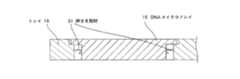
図6はDNAマイクロアレイ15を載せたトレイ16の詳細な構成を示しており、図5のC−C断面図である。 FIG. 6 shows a detailed configuration of the
トレイ16には各DNAマイクロアレイ15を落とし入れることができる段付き穴が形成されており、この穴にDNAマイクロアレイ15が設置される。穴の内側面に押さえ部材31が設けられている。穴にDNAマイクロアレイ15が設置された時、押さえ部材31がDNAマイクロアレイ15を押さえて、DNAマイクロアレイ15はトレイ16内から飛び出さないようになっている。DNAマイクロアレイ15の押さえ方はこの限りではなく、少なくともトレイ16の中から飛び出さないような構造であればよい。なお、このようなトレイ16は、搬送キャリア13を貫通する穴に入れて搬送キャリア13に載置されている(図7〜10参照)。 The
図7〜図10は上述したハイブリダイゼーションを実施するときの装置の動きを順次示している。なお、各図は本実施形態の核酸試料検査装置の一部を示す正面図である。 7 to 10 sequentially show the movement of the apparatus when performing the above-described hybridization. In addition, each figure is a front view which shows a part of nucleic acid sample test | inspection apparatus of this embodiment.
図7ではハイブリダイゼーション直前の状態を表している。複数のDNAマイクロアレイ15を配置したトレイ16と、複数の試薬の入った試薬容器17とが搬送キャリア13上に連結されないで配置されている。所定の反応位置(図5の処理部18)に移動された搬送キャリア13の上方に搬送部19が配置されている。同位置において、DNAマイクロアレイ15の下方には、モーター22、上下動軸23、上下台24、ペルチェ25、ヒートブロック26が配置されている。さらに、DNAマイクロアレイ15の上方には圧接ブロック27が配置されている。また、搬送キャリア13の左隣には検出部21が配置されている。 FIG. 7 shows a state immediately before hybridization. A
図8ではハイブリダイゼーション中の状態を表している。DNAマイクロアレイ15を温度調節するためにモーター22が駆動し、上下動軸23に沿って上下台24が上昇し、DNAマイクロアレイ15の下面とヒートブロック26とが接触する。その後、DNAマイクロアレイ15の上面と、図示しない本体に固定された圧接ブロック27とが接触するまで上昇する。これによって、DNAマイクロアレイ15の下面とヒートブロック26とが密着する。このとき、図6で説明した構造によって、DNAマイクロアレイ15が持ち上がればトレイ16は一緒に搬送キャリア13から浮き上がることになる。次に、ペルチェ25を図示しない制御部で温度制御を開始すると、DNAマイクロアレイ15の温度調節が開始される。DNAマイクロアレイ15上にハイブリダイゼーション用の検体や試薬がセットされればハイブリダイゼーション反応を行うことができる。 FIG. 8 shows a state during hybridization. In order to adjust the temperature of the
図9ではハイブリダイゼーション反応終了後、搬送部19が、DNAマイクロアレイ15を載せたトレイ16を検出部21に搬送した状態である。図8の状態から搬送部19が所定の位置まで移動後、モーター22が駆動され、上下動軸23に沿ってヒートブロック26が下降し、DNAマイクロアレイ15を載せたトレイ16は搬送部19にセットされる。そして、図9に示すように搬送部19がトレイ16を検出部21に移動しセットすると、ハイブリダイゼーション結果の検出が行われる。その後、搬送部19を図7に示される位置に退避させ、搬送キャリア13を図5のように処理部18から離れた位置まで移動させて試薬容器17を回収する。この検査中、必要に応じて、次の検査用のDNAマイクロアレイ15を載せたトレイ16と新しい試薬容器17を搬送キャリア13上にセットすれば、並列処理が可能となる。つまり、本実施形態では、反応後の検出時はDNAマイクロアレイ15を載せたトレイ16のみが検出部21に搬送され、搬送キャリア13には次のサンプルをセット可能となり新たな検査を開始できるため、効率よい並列処理が可能である。また、不要な試薬を検出部21に持ち込まないので検出部21の汚染の心配がない。さらに、DNAマイクロアレイ15を載せたトレイ16のみを検出部21に搬送するため、検出部21を不要に大きくする必要がなくなる。 In FIG. 9, after the hybridization reaction is completed, the
なお、図7〜図9に示したようなハイブリダイゼーションを行なう際に使用する圧接ブロック27にバネをつけることが好ましい。図10はこの構成例を示した図である。ハイブリダイゼーションを行なう際は、DNAマイクロアレイ15の下面とヒートブロック26とが密着させればよく、図10のように圧接ブロック27にバネ28をつけることによって、より安定した圧接力を得ることができる。これにより、DNAマイクロアレイ15とヒートブロック26の密着性が安定する。 In addition, it is preferable to attach a spring to the
上記の実施形態において、ハイブリダイゼーション中は図8に示したようにDNAマイクロアレイ15とトレイ16が搬送キャリア13から浮いている。このため、搬送キャリア13が例えばヒートブロック26と干渉しない範囲であれば、必要に応じて試薬容器17を移動させることも可能である。例えば試薬容器17の位置をずらしてピペッティングするということも可能である。 In the above embodiment, the
また、上記の実施形態では温調機構を上下動させて、反応容器としてのDNAマイクロアレイとヒートブロック26とを密着させる機能と、トレイ16を搬送キャリア13から浮かせる機能とを兼用させているが、温調機構と上下動機構を別々に構成してもよい。 In the above embodiment, the temperature control mechanism is moved up and down to combine the DNA microarray as a reaction container and the
次に、本発明の第2の実施形態について説明する。 Next, a second embodiment of the present invention will be described.
ここでは、上述した第3工程を行なうための搬送キャリア13の周辺機構の別の例を示す。図11は第2の実施形態の核酸試料検査装置の一部を示す正面図である。なお、この図では第1の実施形態と同じ機構、部品には同一符号を付してある。 Here, another example of the peripheral mechanism of the
図11に示すように、第3工程を行なうための搬送キャリア13上には、DNAマイクロアレイ15を載せたトレイ16と、試薬容器17とが配置されている。搬送キャリア13の上面には、トレイ16を固定するためのトレイ固定機構31が配置されている。搬送キャリア13の上方には、トレイ16を上下動可能な搬送部32が配置されている。また、DNAマイクロアレイ15の下方には、モーター22、上下動軸23、上下台24、ペルチェ25、ヒートブロック26が配置されている。搬送キャリア13の左隣には検出部21が配置されている。 As shown in FIG. 11, a
上記構成において、搬送キャリア13は所定の反応位置まで移動すると、反応を開始する。まず、トレイ固定機構31がトレイ16を上から押さえて上下動しないように固定する。次に、モータ22が駆動し、上下動軸23に沿ってヒートブロック26が上昇し、DNAマイクロアレイ15の下面とヒートブロック26が接触する。このとき、トレイ固定機構31がトレイ16を押さえているので、DNAマイクロアレイ15とヒートブロック26との密着性が確保される。次に、ペルチェ25を図示しない制御部で温度制御を開始すると、DNAマイクロアレイ15の温度調節が開始される。DNAマイクロアレイ15
上にハイブリダイゼーション用の検体や試薬がセットされれば、ハイブリダイゼーション反応を行うことができる。次に、ハイブリダイゼーション反応が終了すると、モータ22を駆動させてヒートブロック26は降下する。一方、トレイ固定機構31はトレイ16の固定を解除する。その後、搬送部32がトレイ16を搬送キャリア13から持ち上げて検出部21に搬送する。トレイ16の運搬は、搬送部32の上側に載せてもよいし、あるいは空気で吸引したり、マグネットを用いて搬送部32の下側に配置して運搬したりしてもよい。In the above configuration, when the
If a sample or reagent for hybridization is set on the sample, a hybridization reaction can be performed. Next, when the hybridization reaction is completed, the
以上の第1および第2の実施形態では、DNAマイクロアレイ15はトレイ16上に設置してから、搬送キャリア13に載せるようにしているが、DNAマイクロアレイ15を直接搬送キャリア13に載せるようにしてもよいことは言うまでもない。その場合は、搬送部19又は32は1つずつDNAマイクロアレイ15を検出部21に搬送するか、もしくは複数個のDNAマイクロアレイ15を同時に搬送部19又は32に設置できるようにすればよい。 In the first and second embodiments described above, the
13 搬送キャリア(第1の搬送部)
14 搬送ガイド
15 DNAマイクロアレイ(反応容器)
16 トレイ
17 試薬容器
18 処理部(反応エリア)
19 搬送部(第2の搬送部)
20 搬送ガイド
21 検査部
33 右扉
34 左扉
35 核酸試料検査装置13 Transport carrier (first transport unit)
14 Transport guide 15 DNA microarray (reaction vessel)
16
19 Transport section (second transport section)
20
Claims (3)
Translated fromJapanese検体に所定の処理を行う検体処理部と、 A sample processing unit for performing predetermined processing on the sample;
前記検体を前記検体処理部で処理してできた処理産物と試薬との混合物を反応処理する反応処理部が設置された反応エリアと、 A reaction area provided with a reaction processing unit for reacting a mixture of a processing product and a reagent obtained by processing the sample in the sample processing unit;
試薬の入った1つ以上の試薬容器と、該試薬容器とは連結されていない1つ以上の反応容器とを核酸試料検査装置の外部から載置可能ならびに回収可能とする載置回収エリアと、 A mounting / recovery area in which one or more reagent containers containing a reagent and one or more reaction containers not connected to the reagent container can be mounted and recovered from the outside of the nucleic acid sample testing device;
前記載置回収エリアと前記反応エリアの間を往復移動するキャリアであって前記試薬容器と前記反応容器とを着脱可能に載置する載置部を有するキャリアと、 A carrier that reciprocally moves between the placement and recovery area and the reaction area, the carrier having a placement part for detachably placing the reagent container and the reaction container; and
前記反応エリアに隣接して設置され、前記反応処理部での反応結果を検出する検出部と、 A detection unit that is installed adjacent to the reaction area and detects a reaction result in the reaction processing unit;
前記反応エリアに設置され、前記キャリアの前記載置部から前記反応容器を脱離して前記検出部へ搬送する機構と、 A mechanism installed in the reaction area and desorbing the reaction container from the placement part of the carrier and transporting it to the detection part;
前記検体処理部と前記反応処理部を行き来するピペットを有するピペットユニットと、 A pipette unit having a pipette that moves back and forth between the specimen processing unit and the reaction processing unit;
を有し、 Have
前記試薬容器と前記反応容器の両方を載せた前記キャリアが前記反応エリアに位置しているとき、前記ピペットユニットは、前記ピペットで前記処理産物を前記キャリア上の前記試薬容器へ運び、該試薬容器内の試薬と前記処理産物との混合物を前記キャリア上でさらに前記試薬容器から前記反応容器へ移し、前記反応処理部は、前記キャリア上の前記反応容器の前記混合物を反応処理し、前記機構は、前記キャリアの前記載置部から前記反応容器を脱離して前記検出部へ搬送し、 When the carrier carrying both the reagent container and the reaction container is located in the reaction area, the pipette unit carries the processed product to the reagent container on the carrier with the pipette, and the reagent container The mixture of the reagent and the processed product is further transferred from the reagent container to the reaction container on the carrier, the reaction processing unit reacts the mixture of the reaction container on the carrier, and the mechanism , Detaching the reaction container from the placement part of the carrier and transporting it to the detection part,
前記反応容器が前記検出部に搬送されて前記試薬容器のみが前記キャリア上にあるとき、前記試薬容器のみを載せた前記キャリアは前記載置回収エリアへ移動することを特徴とする核酸試料検査装置。 When the reaction container is transported to the detection unit and only the reagent container is on the carrier, the carrier carrying only the reagent container moves to the above-described collection area, .
前記キャリアの載置部は、前記試薬容器と、前記反応容器を保持する反応容器ホルダーを着脱可能に載置することを特徴とする核酸試料検査装置。 The nucleic acid sample testing apparatus, wherein the carrier mounting section detachably mounts the reagent container and a reaction container holder for holding the reaction container.
Priority Applications (4)
| Application Number | Priority Date | Filing Date | Title |
|---|---|---|---|
| JP2006213357AJP4328788B2 (en) | 2005-10-04 | 2006-08-04 | Nucleic acid sample testing equipment |
| US11/526,616US20070077174A1 (en) | 2005-10-04 | 2006-09-26 | Nucleic acid sample testing apparatus |
| EP06121345.0AEP1826573B1 (en) | 2005-10-04 | 2006-09-27 | Nucleic acid sample testing apparatus |
| KR1020060097485AKR100834586B1 (en) | 2005-10-04 | 2006-10-04 | Nucleic acid sample testing apparatus |
Applications Claiming Priority (2)
| Application Number | Priority Date | Filing Date | Title |
|---|---|---|---|
| JP2005291182 | 2005-10-04 | ||
| JP2006213357AJP4328788B2 (en) | 2005-10-04 | 2006-08-04 | Nucleic acid sample testing equipment |
Publications (2)
| Publication Number | Publication Date |
|---|---|
| JP2007127622A JP2007127622A (en) | 2007-05-24 |
| JP4328788B2true JP4328788B2 (en) | 2009-09-09 |
Family
ID=37845167
Family Applications (1)
| Application Number | Title | Priority Date | Filing Date |
|---|---|---|---|
| JP2006213357AExpired - Fee RelatedJP4328788B2 (en) | 2005-10-04 | 2006-08-04 | Nucleic acid sample testing equipment |
Country Status (4)
| Country | Link |
|---|---|
| US (1) | US20070077174A1 (en) |
| EP (1) | EP1826573B1 (en) |
| JP (1) | JP4328788B2 (en) |
| KR (1) | KR100834586B1 (en) |
Families Citing this family (7)
| Publication number | Priority date | Publication date | Assignee | Title |
|---|---|---|---|---|
| JP4861668B2 (en)* | 2005-09-27 | 2012-01-25 | キヤノン株式会社 | Biochemical reactor, stirring method |
| JP4969650B2 (en) | 2007-06-29 | 2012-07-04 | 凸版印刷株式会社 | Gene detection determination apparatus, gene detection determination method, and gene reaction apparatus |
| JP5650056B2 (en)* | 2011-05-30 | 2015-01-07 | 株式会社日立ハイテクノロジーズ | Sample processing apparatus and sample processing method |
| CN108239601A (en)* | 2018-04-16 | 2018-07-03 | 重庆医科大学附属口腔医院 | A kind of hypoxemia culture and detection integrated system |
| CN114164092B (en)* | 2020-10-19 | 2023-08-15 | 成都瀚辰光翼生物工程有限公司 | Gene detection apparatus |
| CN113755316B (en)* | 2021-10-09 | 2024-12-20 | 苏州国科均豪生物科技有限公司 | Switchable incubation module, PCR amplification detector |
| KR102817128B1 (en)* | 2023-11-28 | 2025-06-05 | (주)제이렘 | Liquid handler device with minimal operator intervention |
Family Cites Families (20)
| Publication number | Priority date | Publication date | Assignee | Title |
|---|---|---|---|---|
| US4803050A (en)* | 1985-07-22 | 1989-02-07 | Sequoia-Turner Corporation | Method and apparatus for liquid addition and aspiration in automated immunoassay techniques |
| US5605665A (en)* | 1992-03-27 | 1997-02-25 | Abbott Laboratories | Reaction vessel |
| US5376313A (en)* | 1992-03-27 | 1994-12-27 | Abbott Laboratories | Injection molding a plastic assay cuvette having low birefringence |
| US5538849A (en)* | 1992-12-29 | 1996-07-23 | Toyo Boseki Kabushiki Kaisha | Apparatus for automated assay of DNA probe and method for assaying nucleic acid in sample |
| JPH0996643A (en)* | 1995-09-29 | 1997-04-08 | Suzuki Motor Corp | Enzyme immunoassay system |
| US5904899A (en)* | 1997-05-15 | 1999-05-18 | Tosoh Corporation | Assaying apparatus and a vessel holder device in use with the assaying apparatus |
| KR100704324B1 (en)* | 1998-05-01 | 2007-04-09 | 젠-프로브 인코포레이티드 | Automated Analytical Instruments and Automated Analytical Methods |
| US6787111B2 (en)* | 1998-07-02 | 2004-09-07 | Amersham Biosciences (Sv) Corp. | Apparatus and method for filling and cleaning channels and inlet ports in microchips used for biological analysis |
| DE69942220D1 (en)* | 1998-07-27 | 2010-05-20 | Hitachi Ltd | Method for handling body fluid samples and analyzer. which uses these |
| US6337490B1 (en)* | 1998-08-06 | 2002-01-08 | Kyoto Daiichi Kagaku Co., Ltd. | Test piece analyzing apparatus having an excessive portion removal |
| EP1041386B1 (en)* | 1999-03-25 | 2007-10-17 | Tosoh Corporation | Analyzer |
| GB2377707B (en)* | 2001-04-26 | 2004-10-20 | Thk Co Ltd | Microarraying head and microarrayer |
| JP2003057236A (en)* | 2001-08-10 | 2003-02-26 | Inst Of Physical & Chemical Res | Biomolecule microarray manufacturing method and spot device |
| WO2003025170A1 (en)* | 2001-09-17 | 2003-03-27 | Hitachi, Ltd. | Sample processing device and sample processing method |
| BRPI0310060B8 (en)* | 2002-05-17 | 2021-07-27 | Becton Dickinson Co | automated system for isolating, amplifying and detecting a target nucleic acid sequence or protein |
| JP3980030B2 (en)* | 2002-08-12 | 2007-09-19 | 株式会社日立ハイテクノロジーズ | Nucleic acid detection method and nucleic acid detection apparatus using DNA microarray |
| US7381370B2 (en)* | 2003-07-18 | 2008-06-03 | Dade Behring Inc. | Automated multi-detector analyzer |
| US7501094B2 (en)* | 2003-09-15 | 2009-03-10 | Syngenta Limited | Preparation and characterization of formulations in a high throughput mode |
| JP4861668B2 (en)* | 2005-09-27 | 2012-01-25 | キヤノン株式会社 | Biochemical reactor, stirring method |
| JP4328787B2 (en)* | 2005-10-04 | 2009-09-09 | キヤノン株式会社 | Nucleic acid sample testing equipment |
- 2006
- 2006-08-04JPJP2006213357Apatent/JP4328788B2/ennot_activeExpired - Fee Related
- 2006-09-26USUS11/526,616patent/US20070077174A1/ennot_activeAbandoned
- 2006-09-27EPEP06121345.0Apatent/EP1826573B1/ennot_activeCeased
- 2006-10-04KRKR1020060097485Apatent/KR100834586B1/ennot_activeExpired - Fee Related
Also Published As
| Publication number | Publication date |
|---|---|
| EP1826573B1 (en) | 2018-04-11 |
| JP2007127622A (en) | 2007-05-24 |
| EP1826573A3 (en) | 2013-11-27 |
| EP1826573A2 (en) | 2007-08-29 |
| KR100834586B1 (en) | 2008-06-09 |
| US20070077174A1 (en) | 2007-04-05 |
| KR20070038017A (en) | 2007-04-09 |
Similar Documents
| Publication | Publication Date | Title |
|---|---|---|
| JP4630786B2 (en) | Biochemical treatment apparatus, DNA amplification and purification apparatus, and DNA testing apparatus including the apparatus | |
| US8747745B2 (en) | Apparatus and method for biochemical analysis | |
| US8323567B2 (en) | Biochemical treatment device with dispensing unit | |
| JP4328788B2 (en) | Nucleic acid sample testing equipment | |
| EP1608952B1 (en) | Assay apparatus and method using microfluidic arrays | |
| US7816120B2 (en) | Temperature controller for structure | |
| US20100190214A1 (en) | Biochemical treatment apparatus and method comprising liquid handling mechanism | |
| US20040141880A1 (en) | System and cartridge for processing a biological sample | |
| JP2008504538A (en) | Equipment for efficient processing of analytical devices | |
| JP2007097476A (en) | Biochemical treatment equipment, containers and inspection equipment used therefor | |
| JP5846773B2 (en) | Sample distribution | |
| US8175810B2 (en) | Sample processing apparatus and sample processing method | |
| JP4328787B2 (en) | Nucleic acid sample testing equipment | |
| JP5384903B2 (en) | Temperature control reaction processing apparatus and temperature control reaction processing method | |
| JP6184806B2 (en) | Automated method for disposing of chips in an automated processing module and processing system comprising a processing module | |
| CN120718747A (en) | Sample analyzer | |
| CN116018410A (en) | Pretreatment mechanism integrated nucleic acid analyzer |
Legal Events
| Date | Code | Title | Description |
|---|---|---|---|
| A977 | Report on retrieval | Free format text:JAPANESE INTERMEDIATE CODE: A971007 Effective date:20080516 | |
| A131 | Notification of reasons for refusal | Free format text:JAPANESE INTERMEDIATE CODE: A131 Effective date:20081001 | |
| A521 | Request for written amendment filed | Free format text:JAPANESE INTERMEDIATE CODE: A523 Effective date:20081128 | |
| A131 | Notification of reasons for refusal | Free format text:JAPANESE INTERMEDIATE CODE: A131 Effective date:20090401 | |
| A521 | Request for written amendment filed | Free format text:JAPANESE INTERMEDIATE CODE: A523 Effective date:20090507 | |
| TRDD | Decision of grant or rejection written | ||
| A01 | Written decision to grant a patent or to grant a registration (utility model) | Free format text:JAPANESE INTERMEDIATE CODE: A01 Effective date:20090603 | |
| A01 | Written decision to grant a patent or to grant a registration (utility model) | Free format text:JAPANESE INTERMEDIATE CODE: A01 | |
| A61 | First payment of annual fees (during grant procedure) | Free format text:JAPANESE INTERMEDIATE CODE: A61 Effective date:20090615 | |
| FPAY | Renewal fee payment (event date is renewal date of database) | Free format text:PAYMENT UNTIL: 20120619 Year of fee payment:3 | |
| R150 | Certificate of patent or registration of utility model | Ref document number:4328788 Country of ref document:JP Free format text:JAPANESE INTERMEDIATE CODE: R150 Free format text:JAPANESE INTERMEDIATE CODE: R150 | |
| FPAY | Renewal fee payment (event date is renewal date of database) | Free format text:PAYMENT UNTIL: 20120619 Year of fee payment:3 | |
| FPAY | Renewal fee payment (event date is renewal date of database) | Free format text:PAYMENT UNTIL: 20130619 Year of fee payment:4 | |
| LAPS | Cancellation because of no payment of annual fees |