JP4328254B2 - Surgery system - Google Patents
Surgery systemDownload PDFInfo
- Publication number
- JP4328254B2 JP4328254B2JP2004105204AJP2004105204AJP4328254B2JP 4328254 B2JP4328254 B2JP 4328254B2JP 2004105204 AJP2004105204 AJP 2004105204AJP 2004105204 AJP2004105204 AJP 2004105204AJP 4328254 B2JP4328254 B2JP 4328254B2
- Authority
- JP
- Japan
- Prior art keywords
- handpiece
- treatment
- identification information
- information
- portable
- Prior art date
- Legal status (The legal status is an assumption and is not a legal conclusion. Google has not performed a legal analysis and makes no representation as to the accuracy of the status listed.)
- Expired - Fee Related
Links
- 238000001356surgical procedureMethods0.000titleclaimsdescription25
- 238000011282treatmentMethods0.000claimsdescription125
- 238000003860storageMethods0.000claimsdescription80
- 238000004891communicationMethods0.000claimsdescription52
- 230000005540biological transmissionEffects0.000claimsdescription37
- 238000001514detection methodMethods0.000claimsdescription5
- 230000003247decreasing effectEffects0.000claimsdescription2
- 238000012545processingMethods0.000claimsdescription2
- 230000007704transitionEffects0.000claims1
- 230000006870functionEffects0.000description32
- 238000000034methodMethods0.000description26
- 230000008569processEffects0.000description25
- 238000010586diagramMethods0.000description16
- 230000008901benefitEffects0.000description15
- 230000033001locomotionEffects0.000description11
- 230000007257malfunctionEffects0.000description10
- 230000015271coagulationEffects0.000description7
- 238000005345coagulationMethods0.000description7
- 230000001954sterilising effectEffects0.000description7
- 238000004659sterilization and disinfectionMethods0.000description7
- 238000004519manufacturing processMethods0.000description5
- 230000000994depressogenic effectEffects0.000description4
- 230000009471actionEffects0.000description3
- 238000005520cutting processMethods0.000description3
- 239000002184metalSubstances0.000description3
- 230000015572biosynthetic processEffects0.000description2
- 230000007797corrosionEffects0.000description2
- 238000005260corrosionMethods0.000description2
- 230000000694effectsEffects0.000description2
- 230000007246mechanismEffects0.000description2
- 230000008054signal transmissionEffects0.000description2
- XLYOFNOQVPJJNP-UHFFFAOYSA-NwaterSubstancesOXLYOFNOQVPJJNP-UHFFFAOYSA-N0.000description2
- 125000002066L-histidyl groupChemical group[H]N1C([H])=NC(C([H])([H])[C@](C(=O)[*])([H])N([H])[H])=C1[H]0.000description1
- 230000001112coagulating effectEffects0.000description1
- 238000013461designMethods0.000description1
- 238000001802infusionMethods0.000description1
- JEIPFZHSYJVQDO-UHFFFAOYSA-Niron(III) oxideInorganic materialsO=[Fe]O[Fe]=OJEIPFZHSYJVQDO-UHFFFAOYSA-N0.000description1
- 238000012986modificationMethods0.000description1
- 230000004048modificationEffects0.000description1
- 230000000704physical effectEffects0.000description1
- 238000003825pressingMethods0.000description1
- 230000002265preventionEffects0.000description1
- 230000004044responseEffects0.000description1
- 230000000717retained effectEffects0.000description1
- 239000000523sampleSubstances0.000description1
Images


Landscapes
- Surgical Instruments (AREA)
Description
Translated fromJapaneseこの発明は、携帯型処置装置と、該携帯型処置装置に対して遠隔操作を行う遠隔操作装置とを備えた手術システムに関するものであって、特に、複数のハンドピースおよび/または複数のフットスイッチを用いた場合であっても複数のハンドピース間に漏電が生じることなく、かつ誤選択等の問題を生じることのない手術システムに関するものである。 The present invention relates to a surgical system including a portable treatment device and a remote operation device for performing remote operation on the portable treatment device, and more particularly, a plurality of handpieces and / or a plurality of foot switches. The present invention relates to a surgical system that does not cause a leakage between a plurality of handpieces and does not cause a problem such as an erroneous selection even when using.
従来、例えば超音波振動を利用することで処置具を振動させて生体組織を切削または凝固する超音波切削装置、超音波凝固装置や、高周波電力による熱作用で生体組織の焼灼を行う電気メス装置、不要な生体組織を粉砕して吸引する超音波吸引装置などの手術装置が知られている。これらの手術装置は、それぞれ患部の処置に関する機能を有することから、実際の外科手術等に使用される場合には、複数のものを使い分けて使用されることが一般的である。 Conventionally, for example, an ultrasonic cutting device that vibrates a treatment tool by using ultrasonic vibration to cut or coagulate a biological tissue, an ultrasonic coagulation device, or an electric scalpel device that cauterizes a biological tissue by a thermal action by high-frequency power Surgical devices such as an ultrasonic suction device that crushes and sucks unnecessary living tissue are known. Since these surgical devices each have a function related to the treatment of the affected area, when they are used in an actual surgical operation or the like, it is general to use a plurality of different devices.
図10−1は、従来の手術装置の構造の一例について示す図である。図10−1に示すように、従来の手術装置は、患部の処置に用いられる処置具を備えたハンドピース101と、ハンドピース101とワイヤ102を介して接続され、ハンドピース101に電流等の駆動エネルギーを供給する本体装置103と、本体装置とワイヤ104を介して接続され、本体装置を制御するフットスイッチ105とを備えた構造を有する。図10−1に示す構成の手術装置を用いて、使用者はハンドピース101を患部に対して固定し、固定後にフットスイッチ105が備える入力ペダル106、107のうち適切なペダルを選択することによって本体装置103から所定の駆動エネルギーが供給され、ハンドピース101を動作させる構造を有する。 FIG. 10A is a diagram illustrating an example of the structure of a conventional surgical apparatus. As shown in FIG. 10A, a conventional surgical apparatus is connected to a
実際の外科手術等では、ハンドピース101を患部に固定する際に片手または両手を用いることがあるため、ハンドピース101側に動作用のスイッチを設けることが好ましくないこともある。従って、従来の手術装置では、動作用のスイッチ手段としてフットスイッチ105を備えた構成とし、使用者が入力ペダル105、106を選択することとしている。かかる構成とすることで、両手を用いてハンドピース101を患部に対して適切に固定した状態を維持したまま、機能の選択を行って所望の処置を行うことが可能である(例えば、特許文献1参照。)。 In actual surgery or the like, since one hand or both hands may be used to fix the
なお、実際の手術においては複数の手術装置を使い分けて必要な処置を行うことに鑑みて、図10−1に示す手術装置を応用して単一の本体装置に複数のハンドピースが接続可能な手術装置が提案されている。図10−2は、かかる構造の手術装置について示すもので、本体装置109に対して複数のハンドピース108a、108b、108cが接続された構造を示している(例えば、特許文献2参照。)。 In actual surgery, a plurality of handpieces can be connected to a single main body device by applying the surgical device shown in FIG. Surgical devices have been proposed. FIG. 10-2 shows a surgical apparatus having such a structure, and shows a structure in which a plurality of
また、大規模な手術においては複数の使用者が同時に処置を行う必要がある。このため、処置を行う使用者の人数分のフットスイッチと、人数分のフットスイッチを接続した本体装置とを備え、本体装置に対して使用するハンドピースが接続された構成の手術装置も提案されている。 In large-scale surgery, it is necessary for a plurality of users to perform treatment at the same time. For this reason, a surgical apparatus having a foot switch for the number of users who perform treatment and a main body device to which the foot switches for the number of people are connected, and a hand piece to be used for the main body device is connected is also proposed. ing.
しかしながら、複数のハンドピースおよび/または複数のフットスイッチを備えた手術システムには様々な問題点が存在する。まず、特に処置具が伝導部材によって形成された電気メス等のハンドピースを同時に複数用いる場合を想定すると、本体装置の大型化という問題が生じる。 However, there are various problems with surgical systems with multiple handpieces and / or multiple footswitches. First, assuming that the treatment tool uses a plurality of handpieces such as electric scalpels formed of a conductive member at the same time, there arises a problem that the main unit is enlarged.
図11は、複数のハンドピース108a、108bを別個の本体装置に接続した状態で使用した場合を模式的に示す図である。通常の本体装置は家庭用電源から電気エネルギーを得る構成を有し、本体装置はコンセントを家庭用電源に接続した状態で使用される。このため、複数の、例えば処置具に導電性部材を有する電気メス等のハンドピース108a、108bを使用した場合、図11に示すような電気的ループ111が形成されてしまう。電気的ループ111が形成された際にはハンドピース108a、108b間に電流が流れることとなり、患者の身体のうち、ハンドピース間に位置する領域を損傷させるおそれがある。 FIG. 11 is a diagram schematically illustrating a case where a plurality of
例えば、バイポーラ電極を備えたハンドピースは、同一ハンドピースにおける電極間に高周波電流を流すことによって所定の処置を行うが、複数のハンドピースを同時に使用することでかかる高周波電流が異なるハンドピース間に流れることとなり、患部以外の人体組織に対して損傷を与え、危険である。 For example, a handpiece having a bipolar electrode performs a predetermined treatment by flowing a high-frequency current between the electrodes in the same handpiece. However, when a plurality of handpieces are used at the same time, the high-frequency current is different between handpieces. It will flow and damage human tissue other than the affected area, which is dangerous.
従って、従来の手術装置では、電気的ループ111が形成されぬよう本体装置内部にトランス回路等を設け、ハンドピースとコンセントとの間を直接的に導通させない構成としている。さらに、実際には二重、三重の安全装置機構を設ける場合もあり、製造コスト上大きな問題となっていた。 Therefore, in the conventional surgical apparatus, a transformer circuit or the like is provided in the main body apparatus so that the electric loop 111 is not formed, and the handpiece and the outlet are not directly connected. Furthermore, in practice, there are cases where double and triple safety device mechanisms are provided, which is a serious problem in terms of manufacturing cost.
また、複数のハンドピースおよび/または複数のフットスイッチを同時に使用する場合、本体装置と接続するために必要なワイヤの本数の増加が他の問題として挙げられる。すなわち、従来の手術装置では、フットスイッチ、ハンドピースと本体装置との間はワイヤで接続された構造を有することから、フットスイッチおよびハンドピースの数だけ接続用のワイヤが必要となる。従って、多種類の処置や、多数の使用者が必要となる手術の場合には、手術室内に多数のワイヤが張り巡らされた状態となり、使用者の移動が制限されると共に、医療器具の搬入にも支障を来すこととなる。 In addition, when a plurality of handpieces and / or a plurality of footswitches are used at the same time, an increase in the number of wires necessary for connection with the main body device is another problem. That is, the conventional surgical device has a structure in which the foot switch, the hand piece, and the main body device are connected by a wire, and therefore, as many wires as the number of the foot switch and the hand piece are required for connection. Therefore, in the case of many types of treatments or operations that require a large number of users, a large number of wires are stretched around the operating room, which restricts the movement of the user and allows the delivery of medical instruments. Will also be a hindrance.
さらに、ハンドピースがワイヤに接続される構成の手術装置の場合、滅菌の際にハンドピースが損傷するおそれがある。ハンドピースとワイヤとの間は電気的に接続されることから、ハンドピース側の接続部は金属等の導電性部材によって構成される一方、ハンドピースは外科的処置に直接用いられることから衛生上の観点から使用ごとに滅菌処理を行う必要がある。従って、ハンドピースからワイヤを外して滅菌処理を行った場合には、接続部が直接滅菌雰囲気にさらされることとなり、導電性部材の錆、腐食等が問題となる。ハンドピース側において開閉可能な蓋構造等を、接続部を覆うように設けることで接続部を滅菌雰囲気からある程度遮蔽することは可能であるが、完全に遮蔽する構造は現実には容易ではなく、製造上の負担が増大する等の問題を有する。 Furthermore, in the case of a surgical apparatus configured such that the handpiece is connected to a wire, the handpiece may be damaged during sterilization. Since the handpiece and the wire are electrically connected, the connection part on the handpiece side is made of a conductive member such as metal, while the handpiece is used directly for surgical procedures. From this point of view, it is necessary to sterilize each use. Therefore, when the wire is removed from the handpiece and sterilization is performed, the connection portion is directly exposed to the sterilization atmosphere, and rust and corrosion of the conductive member become a problem. It is possible to shield the connection part from the sterilization atmosphere to some extent by providing a lid structure that can be opened and closed on the handpiece side so as to cover the connection part, but the structure that completely shields is not easy in reality, There are problems such as an increased manufacturing burden.
また、複数のハンドピースを使用する場合、ハンドピースの誤選択を防ぐ必要がある。すなわちフットスイッチのペダルを踏んだ際に、使用を想定したハンドピースと異なるハンドピースが動作することを避ける必要がある。これは、単一のフットスイッチに対して複数のハンドピースを使用する場合のみならず、複数のフットスイッチと複数のハンドピースを使用する場合に特に問題となる。すなわち、第1の使用者が第1のフットスイッチの制御により第1のハンドピースを動作させ、第2の使用者が第2のフットスイッチの制御により第2のハンドピースを動作させているときに、突如第2の使用者の第2のフットスイッチによって第1のハンドピースが動作することは、操作の安全確保のために、絶対に避ける必要がある。 Moreover, when using several handpieces, it is necessary to prevent the misselection of a handpiece. That is, when a foot switch pedal is depressed, it is necessary to avoid the movement of a handpiece that is different from the handpiece intended for use. This is a particular problem not only when using multiple handpieces for a single footswitch, but also when using multiple footswitches and multiple handpieces. That is, when the first user operates the first handpiece by controlling the first foot switch, and the second user operates the second handpiece by controlling the second foot switch In addition, sudden movement of the first handpiece by the second foot switch of the second user must be avoided to ensure the safety of operation.
この発明は、上記従来技術の問題点に鑑みてなされたものであって、複数のハンドピースおよび/または複数のフットスイッチを用いた場合であっても複数のハンドピース間に漏電が生じることなく、かつ誤選択等の問題を生じることのない手術システムを提供することを目的とする。 The present invention has been made in view of the above problems of the prior art, and even when a plurality of handpieces and / or a plurality of foot switches are used, no leakage occurs between the plurality of handpieces. An object of the present invention is to provide a surgical system that does not cause problems such as erroneous selection.
上記目的を達成するため、請求項1にかかる手術システムは、処置対象に所定の処置を実行する携帯型処置装置と、該携帯型処置装置に対して遠隔操作を行う遠隔操作装置と、を備えた手術システムにおいて、前記遠隔操作装置は、当該遠隔操作装置に割り当てられた操作装置識別情報を記憶する第1記憶手段と、当該遠隔操作装置と対応付けられた前記携帯型処置装置に割り当てられた処置装置識別情報を記憶する第2記憶手段と、前記携帯型処置装置の動作内容を入力する入力手段と、前記携帯型処置装置との間で無線交信を行う操作装置側交信手段と、前記操作装置側交信手段を介して前記携帯型処置装置へ前記操作装置識別情報と前記処置装置識別情報と前記動作内容とを含む操作情報を送信する操作情報送信手段と、を有し、前記携帯型処置装置は、前記所定の処置を実行する処置部と、前記処置部に駆動エネルギーを供給する駆動手段と、前記処置装置識別情報を記憶する第3記憶手段と、前記操作装置識別情報を記憶する第4記憶手段と、前記遠隔操作装置との間で無線交信を行う処置装置側交信手段と、前記処置装置側交信手段を介して前記遠隔操作装置から入力された前記操作情報に前記第3記憶手段に記憶されている前記処置装置識別情報および前記第4記憶手段に記憶されている前記操作装置識別情報が含まれているか否かを判定する判定手段と、前記判定手段による判定の結果、前記操作情報に前記第3記憶手段に記憶されている前記処置装置識別情報および前記第4記憶手段に記憶されている前記操作装置識別情報が含まれている場合、前記操作情報に含まれている前記動作内容に従って前記駆動手段が前記処置部へ供給する駆動エネルギーを増減する駆動エネルギー制御手段と、当該携帯型処置装置の外壁を形成し、前記処置部の少なくとも一部を前記処置対象に対して露出可能な絶縁性のケース部材と、を有することを特徴とする。To achieve the above object, the surgical system according to claim 1 is provided with a portable treatment apparatusfor executing a predetermined treatment in the treatment target, a remote control apparatus for performing remote operations on the portable treatmentapparatus, the In the surgical system, theremote operation device is assigned to the first storage means for storing the operation device identification information assigned to the remote operation device and the portable treatment device associated with the remote operation device. Second storage means for storing treatment device identification information, input means for inputting operation contents of the portable treatment device, operation device side communication means for performing wireless communication with the portable treatment device, and the operation via the device side communication means have an operation information transmitting means for transmitting the operation information including said operation content and the to the portable treatment apparatus and the operation apparatus identification information the treatment device identification information, the Banded treatment apparatus includesa treatment portion for performing a predetermined treatment, and driving means for supplying driving energy to the treatment section, a third storage means for storing the treatment device identification information, the operation apparatus identification information A fourth storage means for storing ; a treatment apparatus side communication means for performing wireless communication with the remote operation apparatus; and theoperation information input from the remote operation apparatus via the treatment apparatus side communication means. 3 determination means for determining whether or not the treatment device identification information stored in the storage means and the operating device identification information stored in the fourth storage means are included, and a result of determination by the determination means When the operation information includes the treatment device identification information stored in the third storage means and the operation device identification information stored in the fourth storage means, the operation information includes Drive energy control means for increasing or decreasing the drive energy supplied by the drive means to the treatment section according to the operation details that are present, and forming an outer wall of the portable treatment apparatus, and at least a part of the treatment section is the treatment target andhavinga aninsulating case membercapable exposed to.
この請求項1の発明によれば、携帯型処置装置と遠隔操作装置との間で無線交信を行うこととしたため、信号伝送用のワイヤ等が不要となると共に、滅菌の際に損傷する接続部を省略した構造とすることができる。また、ハンドピースが処置部材以外についてケース部材によって外部と電気的に絶縁されることとしたため、同時に複数のハンドピースを使用した場合であっても、電気的ループの形成による高周波電流または低周波電流の漏電の発生を防止することができる。 According to the first aspect of the present invention, since wireless communication is performed between the portable treatment device and the remote control device, a signal transmission wire or the like is not necessary, and the connection portion is damaged during sterilization. The structure can be omitted. In addition, since the handpiece is electrically insulated from the outside by the case member except for the treatment member, even when a plurality of handpieces are used at the same time, a high-frequency current or a low-frequency current due to the formation of an electrical loop The occurrence of earth leakage can be prevented.
また、請求項2にかかる手術システムは、上記の発明において、前記携帯型処置装置は、少なくとも前記処置装置側交信手段をオン状態に維持し且つ少なくとも前記駆動手段をオフ状態に維持するスタンバイモードと、少なくとも前記処置装置側交信手段および前記駆動手段をオン状態に維持するレディモードと、を有し、前記操作情報送信手段は、前記操作装置側交信手段を介して前記携帯型処置装置へ前記操作装置識別情報と前記処置装置識別情報とを含むスタンバイモード解除情報を送信し、前記判定手段は、前記処置装置側交信手段を介して前記遠隔操作装置から入力された前記スタンバイモード解除情報に前記第3記憶手段に記憶されている前記処置装置識別情報および前記第4記憶手段に記憶されている前記操作装置識別情報が含まれているか否かを判定し、前記携帯型処置装置は、前記判定手段による判定の結果、前記スタンバイモード解除情報に前記第3記憶手段に記憶されている前記処置装置識別情報および前記第4記憶手段に記憶されている前記操作装置識別情報が含まれている場合、前記スタンバイモードから前記レディモードに移行することを特徴とする。In the surgical system according to claim2 , in the above-described invention, the portable treatment device includes a standby mode in whichat least the treatment device side communication unit is maintained in an on stateand at least the drive unit is maintained in an off state. A ready mode for maintainingat least the treatment device side communication means and the driving means in an ON state, andtheoperation information transmitting means operates the portable treatment device via the operation device side communication means. The standby mode release information including device identification information and the treatment device identification information is transmitted, and the determination means adds the standby mode release information to the standby mode release information input from the remote operation device via the treatment device side communication means. 3 The treatment device identification information stored in the storage means and the operation device identification information stored in the fourth storage means The portable treatment device determines whether the treatment device identification information and the fourth storage stored in the third storage device are stored in the standby mode release information as a result of the determination by the determination device. When the operation device identification information stored in the means is included, the standby mode is shifted to the ready mode.
また、請求項3にかかる手術システムは、上記の発明において、前記駆動手段は、前記操作装置側交信手段から発信される出力信号を受信している間のみ動作し、該出力信号の受信の終了と共に動作を終了することを特徴とする。In the surgical system according to athird aspect of the present invention, in the above invention, the driving means operates only while receiving an output signal transmitted from the operating device side communication means, and the reception of the output signal is completed. And the operation is terminated.
また、請求項4にかかる手術システムは、上記の発明において、複数の前記携帯型処置装置を着脱可能に保持する保持部と、前記保持部に保持された1つ以上の携帯型処置装置の処置装置識別情報をそれぞれ検知する情報検知手段と、前記情報検知手段で検出した前記1つ以上の処置装置識別情報を記憶する第5記憶手段と、前記第5記憶手段に記憶された処理装置識別情報のうち前記情報検知手段で検知不能となった処置装置識別情報を含む保持情報を前記遠隔操作装置側に送信する送信手段と、を有する保持装置をさらに備えたことを特徴とする。Moreover, the surgical system according to
また、請求項5にかかる手術システムは、上記の発明において、前記遠隔操作装置は、前記保持情報を受信し、該保持情報に基づいて選択可能な前記携帯型処理装置を認識することを特徴とする。Moreover, the surgical system according to claim5, in the above invention, the remote operation device includes wherein receiving theretained information, recognizes a selectable the portable processor based on the informationheld To do.
また、請求項6にかかる手術システムは、複数の前記携帯型処置装置と、前記複数の携帯型処置装置それぞれに着脱可能であって該複数の携帯型処置装置それぞれに対して電力を供給可能な電源部と、を備え、前記遠隔操作装置は、前記電源部が接続された前記携帯型処置装置を選択して遠隔操作することを特徴とする。The surgical operation system according to
また、請求項7にかかる手術システムは、上記の発明において、前記遠隔操作装置は、前記携帯型処置装置の動作内容がそれぞれ対応付けられた複数の前記入力手段を有することを特徴とする。Moreover, the surgical system according to
また、請求項8にかかる手術システムは、上記の発明において、異なる前記携帯型処置装置の動作のうち共通性を有する動作内容は、同一の前記入力手段に対応付けられていることを特徴とする。Moreover, the surgical system according to
本発明にかかる手術システムは、携帯型処置装置と遠隔操作装置との間で無線交信を行う構成としたため、信号伝送用のワイヤ等が不要となると共に、滅菌の際に損傷する接続部を省略した構造とすることができるという効果を奏する。また、ハンドピースが処置部材以外についてケース部材によって外部と電気的に絶縁される構成としたため、同時に複数のハンドピースを使用した場合であっても、電気的ループの形成による高周波電流または低周波電流の漏電の発生を防止できるという効果を奏する。 Since the surgical system according to the present invention is configured to perform wireless communication between the portable treatment device and the remote control device, a signal transmission wire or the like is not necessary, and a connection portion that is damaged during sterilization is omitted. There is an effect that the structure can be achieved. Further, since the handpiece is electrically insulated from the outside by the case member except for the treatment member, even when a plurality of handpieces are used at the same time, a high-frequency current or a low-frequency current due to the formation of an electrical loop It is possible to prevent the occurrence of electrical leakage.
以下、図面を参照して、この発明の実施の形態である手術システムについて説明する。図面は模式的なものであり、各部分の厚みと幅との関係、それぞれの部分の厚みの比率などは現実のものとは異なることに留意すべきであり、図面の相互間においても互いの寸法の関係や比率が異なる部分が含まれていることはもちろんである。さらに、符号に付くa、b等の識別文字は必要に応じて付けるものとし、“フットスイッチ1a、1b”のように複数の同一部分が存在する場合には、必要に応じて“フットスイッチ1”と総称して記述する。 Hereinafter, a surgical system according to an embodiment of the present invention will be described with reference to the drawings. It should be noted that the drawings are schematic, and the relationship between the thickness and width of each part, the ratio of the thickness of each part, and the like are different from the actual ones. Of course, parts with different dimensional relationships and ratios are included. Further, identification characters such as “a” and “b” attached to the reference numerals are attached as necessary. When there are a plurality of identical parts such as “foot switches 1a, 1b”, “foot switch 1” is added as necessary. "And generically.
(実施の形態1)
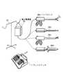
まず、この発明の実施の形態1にかかる手術システムについて説明する。図1は、実施の形態1にかかる手術システムの構成を示す模式図である。図1に示すように、実施の形態1にかかる手術システムは、遠隔操作装置たるフットスイッチ1と、携帯型処置具たるハンドピース2とを複数備えた構造を有する。図1ではそれぞれフットスイッチ1と、ハンドピース2とを2個ずつ備えた構成について示すが、それぞれの個数に限定が無いことはもちろんである。(Embodiment 1)
First, the surgery system according to the first embodiment of the present invention will be described. FIG. 1 is a schematic diagram illustrating a configuration of the surgery system according to the first embodiment. As shown in FIG. 1, the surgical system according to the first embodiment has a structure including a plurality of foot switches 1 that are remote control devices and handpieces 2 that are portable treatment tools. Although FIG. 1 shows a configuration in which two foot switches 1 and two handpieces 2 are provided, the number of each is not limited.
フットスイッチ1は、ハンドピース2の動作を制御するためのものである。具体的には、フットスイッチ1は、入力ペダル3、4と、入力ペダル3、4で入力された情報等を処理する制御部5と、制御部5から得られた内容の情報に基づいて無線交信を行う送受信部6と、制御部5および送受信部6に駆動エネルギーを供給する電源部7とを有する。さらに、フットスイッチ1は、交信対象たるハンドピース2のIDを記憶し、制御部5に対して入出力可能なハンドピースID記憶部8と、自己のIDを記憶し、制御部5に出力可能な自己ID記憶部9と、制御対象をハンドピース2a、2bの中から選択するための切替スイッチ10とを備える。 The foot switch 1 is for controlling the operation of the handpiece 2. Specifically, the foot switch 1 is wirelessly based on
入力ペダル3、4は、選択したハンドピース2の動作内容を決定するためのものである。入力動作の態様はいかなる構造とすることも可能であるが、本実施の形態においては入力ペダル3、4のいずれかを使用者が足で踏むことによってハンドピース2の動作内容が決定されることとする。 The
送受信部6は、ハンドピース2との間で無線交信を行うためのものである。送受信部6は、ハンドピース2から受信した情報を制御部5に伝達する一方、制御部5からの情報をハンドピース2に対して発信する機能を有する。 The transmitting / receiving
ハンドピースID記憶部8は、交信対象たるハンドピース2のIDを記憶するためのものである。ハンドピースID記憶部8は、あらかじめ定められたハンドピース2のIDのみを記憶した書き換え不可能なメモリ等によって構成されても良いが、本実施の形態1ではデータ書き換え可能な構造を有するものとする。 The handpiece
自己ID記憶部9は、フットスイッチ1自身のIDを記憶するためのものである。フットスイッチ1a、1bはそれぞれ個別のIDが割り当てられており、自己ID記憶部9は、それぞれに割り当てられたIDを記憶している。かかるIDについては書き換えの必要がないことから、自己ID記憶部9は、書き換え不可能なメモリ等を備えることが好ましい。 The self
なお、以下の説明ではフットスイッチ1aのIDを“ID[FSW1a]”とし、フットスイッチ1bのIDを“ID[FSW1b]”とする。また、任意のフットスイッチのIDを称する際には“ID[FSWX]として説明を行う。 In the following description, the ID of the foot switch 1a is “ID [FSW1a]” and the ID of the foot switch 1b is “ID [FSW1b]”. Further, when referring to the ID of an arbitrary foot switch, the description will be given as “ID [FSWX]”.
また、制御部5は、入力ペダル3、4、ハンドピースID記憶部8、自己ID記憶部9bからの情報に基づいて送受信部6の発信情報の内容を決定すると共に、送受信部6で受信した情報の解析を行うためのものである。かかる制御部5の機能については、後に詳細に説明する。 Further, the control unit 5 determines the content of the transmission information of the transmission /
次に、ハンドピース2の構成について説明する。ハンドピース2は、無線交信を介したフットスイッチ1からの制御を受けて患部に対して所定の動作を行うためのものである。具体的には、ハンドピース2は、患部に対して物理的作用を施す処置部材12と、処置部材12に駆動エネルギーを供給する駆動部13と、駆動部13の状態等を制御する制御部14と、フットスイッチ1との無線交信を行う送受信部15と、駆動部13、制御部14および送受信部15に対して駆動エネルギーを供給する電源部16を有する。また、ハンドピース2は、交信対象であるフットスイッチ1のIDを記憶し、制御部14に対して入出力可能なフットスイッチID記憶部17と、自己のIDを記憶し、制御部14に出力可能な自己ID記憶部18とを有する。さらに、ハンドピース2は、処置部材12以外の上記要素を内部に包含するケース部材19を有する。 Next, the configuration of the handpiece 2 will be described. The handpiece 2 is for performing a predetermined operation on the affected area under the control of the foot switch 1 via wireless communication. Specifically, the handpiece 2 includes a
処置部材12は、患部に対して直接的に作用を施すためのものである。処置部材12の具体的な構造はハンドピース2に持たせる機能によって異なるものとなる。例えば、ハンドピース2が電気メスとして用いられる場合には、処置部材12はモノポーラ電極またはバイポーラ電極を先端部に有し、かかる電極から供給される高周波電流によって患部を加熱、切断する構造を有する。また、超音波ハンドピースの場合には、超音波振動子と、超音波振動子によって得られた振動を先端部に伝えるためのプローブとを備えた構造を有する。 The
駆動部13は、処置部材12に対して駆動エネルギーを供給するためのものである。なお、駆動部13の構造および出力する駆動エネルギーの値等は処置部材12の構造に対応して異なるものとなる。 The
制御部14は、フットスイッチ1との交信によって得られた内容に基づいて駆動部13を制御する。具体的には、フットスイッチ1で決定された動作内容を駆動部13に伝達し、駆動部13は動作内容に対応した駆動エネルギーを処置部材12に対して供給する。また、制御部14は、送受信部15で受信された交信内容が自己に向けたものなのか否かおよび正しいフットスイッチから発信されたものなのか否か等の判断も行う。かかる機能については後に詳しく説明する。 The
送受信部15は、フットスイッチ1との間で無線交信を行うためのものである。具体的には、送受信部15は、フットスイッチ1から受信した情報を制御部14に伝達する一方、制御部14からの情報をフットスイッチ1へ発信する機能を有する。 The transmitting / receiving
フットスイッチID記憶部17は、交信対象であるフットスイッチ1のIDを記憶するためのものである。フットスイッチID記憶部17は、ハンドピースID記憶部8と同様にあらかじめ与えられた内容を記憶する書き換え不可能なメモリ等によって構成されても良いが、本実施の形態1ではデータ書き換え可能なものを有することとする。 The foot switch
自己ID記憶部18は、ハンドピース2自身のIDを記憶するためのものである。かかるIDは書き換えの必要がないことから、自己ID記憶部18は書き換え不可能なメモリ等を備えた構造とすることが好ましい。なお、以下の説明ではハンドピース2aのIDを“ID[HP2a]”とし、ハンドピース2bのIDを“ID[HP2b]”とする。また、任意のハンドピースのIDを称する際には“ID[HPY]”として説明を行う。 The self
ケース部材19は、駆動部13〜電源部16等の電子機器を外部から電気的に遮蔽するためのものである。具体的には、ケース部材19は、絶縁性プラスチック等によって形成され、駆動部13等を内部に包含する構造を有する。なお、後述する理由により、ケース部材19はハンドピース2を使って患部に処置を行う際に電気的遮蔽効果を発揮すれば十分であり、不使用時には遮蔽しない構造であっても良い。 The case member 19 is for electrically shielding electronic devices such as the
次に、本実施の形態1にかかる手術システムの動作について説明する。本実施の形態1にかかる手術システムは、上記のようにフットスイッチおよびハンドピースを複数備え、相互間において無線交信によって制御が行われる構造を有する。従って、例えば一方のハンドピースを動作させたいにも関わらず他方のハンドピースが動作するといった事態を生じる可能性があり、かかる事態の発生を防止する機構が必要となる。そこで、本実施の形態1にかかる手術システムでは、個々のフットスイッチ、ハンドピース毎に異なるIDを割り当てることによって誤動作を防止している。以下では、誤動作を防止する前提として無線交信の相手方のIDを登録するプロセスについて説明した後、自己および交信相手のIDを含む無線交信による動作について説明し、誤動作が防止されることを示す。 Next, operation | movement of the surgery system concerning this Embodiment 1 is demonstrated. The surgical system according to the first embodiment includes a plurality of foot switches and handpieces as described above, and has a structure in which control is performed by wireless communication between each other. Therefore, for example, there is a possibility that a situation occurs in which the other handpiece operates despite the desire to operate one handpiece, and a mechanism for preventing the occurrence of such a situation is required. Therefore, in the surgical system according to the first embodiment, malfunctions are prevented by assigning different IDs to individual foot switches and handpieces. In the following, after describing the process of registering the ID of the other party of the wireless communication as a premise for preventing the malfunction, the operation by the wireless communication including the self and the ID of the other party will be described to show that the malfunction is prevented.
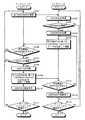
まず、フットスイッチ1およびハンドピース2において無線交信の相手方のIDを登録するプロセスについて説明する。図2は、無線交信の相手方のIDを登録するプロセスを示すフローチャートであり、以下では図2を参照しつつ説明する。 First, the process of registering the ID of the other party of wireless communication in the foot switch 1 and the handpiece 2 will be described. FIG. 2 is a flowchart showing a process of registering the ID of the other party of the wireless communication, and will be described below with reference to FIG.
まず、フットスイッチ1は、送受信部6から自己のIDである“ID[FSWX]”を発信する(ステップS101)。ハンドピース2は、駆動部13がオフ状態である一方、送受信部15がオン状態となるスタンバイモードとなっており、かかるフットスイッチ1から発信した情報を送受信部15で受信して、制御部14に伝達する(ステップS102)。 First, the foot switch 1 transmits “ID [FSWX]”, which is its own ID, from the transmission / reception unit 6 (step S101). The handpiece 2 is in a standby mode in which the
そして、ハンドピース2において、制御部14は、受信した“ID[FSWX]”が特定のフットスイッチのIDであることを認識した上で、登録するか否かを判定する(ステップS103)。登録しないと判定した場合、IDを受信したフットスイッチ1の登録は行わず、後述のステップS114に移行する。一方、登録すると判定した場合には、制御部14は、フットスイッチID記憶部17に“ID[FSWX]”を記憶させる(ステップS104)。 Then, in the handpiece 2, the
その後、ハンドピース2の制御部14は、自己のIDである“ID[HPY]”と、受信した“ID[FSWX]”とを含むデータを生成し、送受信部15から発信する(ステップS105)。 Thereafter, the
その後、ステップS105で発信された情報はフットスイッチ1側の送受信部6によって受信され、受信された情報の中に自己のIDである“ID[FSWX]”が含まれているか否かが制御部5によって判定される(ステップS106)。自己のIDに関する情報が含まれていない場合にはハンドピース2での登録が失敗したものと判断して、再びステップS101に戻って自己のIDを発信する。一方、自己のIDに関する情報が含まれていると判定された場合には、ステップS107に移行する。 Thereafter, the information transmitted in step S105 is received by the transmission /
そして、制御部5は、自己のIDに関する情報と共に受信した“ID[HPY]”を認識し、“ID[HPY]”を登録するか否かを判定する(ステップS107)。登録しないと判定した場合には、後述のステップS111に移行する。一方、登録すると判定した場合にはステップS108に移行する。 Then, the control unit 5 recognizes “ID [HPY]” received together with the information related to its own ID, and determines whether or not to register “ID [HPY]” (step S107). If it is determined not to register, the process proceeds to step S111 described later. On the other hand, if it is determined to register, the process proceeds to step S108.
その後、制御部5は、受信した“ID[HPY]”をハンドピースID記憶部8に転送し、記憶させる(ステップS109)。そして、制御部5は、自己のIDである“ID[FSWX]”と、記憶したハンドピース2のIDである“ID[HPY]”とを含む“ID[FSWX]+ID[HPY]+received”なるデータを生成し、発信する(ステップS109)。かかるデータは、フットスイッチ1がハンドピースのIDを取得し、登録を行った旨をハンドピース2側に通知するためのものである。 Thereafter, the control unit 5 transfers the received “ID [HPY]” to the handpiece
以上で、フットスイッチ1側の“ID[HPY]”に関する登録作業は完了し(ステップS110)、複数存在するすべてのハンドピースについて登録が完了したか否かの判定を行う(ステップS111)。すべての必要なハンドピース2の登録が未完了であれば再びステップS101に戻ってIDを発信し、完了していればすべての処理を終了する。 This completes the registration work related to “ID [HPY]” on the foot switch 1 side (step S110), and determines whether or not registration has been completed for all the handpieces that exist in plural (step S111). If registration of all necessary handpieces 2 is not completed, the process returns to step S101 again to send an ID, and if completed, all processing is terminated.
一方、ハンドピース2は、ステップS109におけるフットスイッチ1からの“ID[FSWX]+ID[HPY]+received”を送受信部15にて受信し、自己のIDが含まれるか否かを判定する(ステップS112)。自己のIDが含まれていないと判定した場合にはステップS105に戻り、再び自己IDおよびステップS102で受信したフットスイッチ1のIDを発信する。自己のIDが含まれていると判定した場合には、フットスイッチ1側で自己のIDが登録されたものと判断し、“ID[FSWX]”に関する登録作業を完了する(ステップS113)。 On the other hand, the handpiece 2 receives “ID [FSWX] + ID [HPY] + received” from the foot switch 1 in step S109 by the transmission /
そして、複数存在するうち必要なすべてのフットスイッチ1のID登録が完了したか否かを判定する(ステップS114)。完了していない場合には再びステップS102に戻って他のフットスイッチ1からの発信情報を受信する態勢をとり、完了した場合にはすべての処理を終了する。 Then, it is determined whether or not the ID registration of all necessary foot switches 1 among the plurality is completed (step S114). If it is not completed, the process returns to step S102 again to receive the transmission information from the other foot switch 1, and if completed, all the processes are terminated.
以上のプロセスを経ることによってフットスイッチ1のハンドピースID記憶部8およびハンドピース2のフットスイッチID記憶部17に登録対象である無線交信の相手方のIDが記憶される。かかるIDは、以下に説明する無線交信による動作プロセスにおいて重要な役割を果たす。 Through the above process, the ID of the wireless communication partner to be registered is stored in the handpiece
次に、ID登録が行われたフットスイッチ1とハンドピース2との間の無線交信によってハンドピース2を動作させるプロセスについて説明する。図3は、無線交信を用いた動作プロセスを説明するためのフローチャートであって、以下では図3を参照して説明を行う。 Next, a process for operating the handpiece 2 by wireless communication between the foot switch 1 and the handpiece 2 for which ID registration has been performed will be described. FIG. 3 is a flowchart for explaining an operation process using wireless communication, and will be described below with reference to FIG.
まず、フットスイッチ1の切替スイッチ10によって使用するハンドピース2を選択する(ステップS201)。ここで、選択したハンドピース2は、フットスイッチ1のハンドピースID記憶部8にIDが登録されているものとする。一方、この時点ですべての使用可能なすべてのハンドピース2は、駆動部13がオフ状態であり、送受信部15がオン状態であるスタンバイ状態となっている(ステップS202)。 First, the handpiece 2 to be used is selected by the changeover switch 10 of the foot switch 1 (step S201). Here, it is assumed that the ID of the selected handpiece 2 is registered in the handpiece
そして、フットスイッチ1の制御部5は、自己の“ID[FSWX]”と、選択したハンドピース2の“ID[HPY]”とに基づいて、“ID[FSWX]+ID[HPY]+selected”を発信する(ステップS203)。かかるデータは、“ID[FSWX]”を備えたフットスイッチ1が、“ID[HPY]”を備えたハンドピースを選択(select)した旨を意味する。 Then, the control unit 5 of the foot switch 1 sets “ID [FSWX] + ID [HPY] + selected” based on its own “ID [FSWX]” and “ID [HPY]” of the selected handpiece 2. A call is made (step S203). Such data means that the foot switch 1 having “ID [FSWX]” has selected a handpiece having “ID [HPY]”.
その後、複数のハンドピース2は、それぞれステップS203で発信された情報を受信し、受信したデータの中に自己のIDに関する情報が含まれるかを判定する(ステップS204)。自己のIDに関する情報が含まれない場合は、フットスイッチ1は自己を使用するのではないと判断して再びステップS202に戻ってスタンバイモードを維持する。一方、自己のIDが含まれていると判定した場合には、送受信部15および駆動部13をオンしたレディモードに移行し、以降のフットスイッチ1の指示を待つ(ステップS205)。 Thereafter, each of the plurality of handpieces 2 receives the information transmitted in step S203, and determines whether the received data includes information regarding its own ID (step S204). If the information related to its own ID is not included, the foot switch 1 determines that it does not use itself and returns to step S202 again to maintain the standby mode. On the other hand, if it is determined that the self ID is included, the mode is shifted to the ready mode in which the transmission /
その後、フットスイッチ1において、選択したハンドピース2に行わせる動作を入力ペダル3、4によって決定する(ステップS206)。具体的には、入力ペダル3、4にはハンドピース2ごとに定められた処置が割り当てられており、入力ペダル3、4のいずれかを選択することによって、ハンドピース2の動作内容が決定される。 Thereafter, the operation to be performed by the selected handpiece 2 in the foot switch 1 is determined by the
そして、フットスイッチ1は、自己のIDである“ID[FSWX]”と、選択したハンドピース2のIDである“ID[HPY]”と、ステップS206で選択した動作内容に対応した“output”とを含む“ID[FSWX]+ID[HPY]+output”を発信する(ステップS207)。その後、フットスイッチ1は、入力ペダル3および入力ペダル4の選択が解除されたか判定し(ステップS208)、入力ペダル3または入力ペダル4が選択されている間はステップS207に戻って発信動作を継続する。 Then, the foot switch 1 has its own ID “ID [FSWX]”, the ID of the selected handpiece 2 “ID [HPY]”, and “output” corresponding to the operation content selected in step S206. "ID [FSWX] + ID [HPY] + output" including "is transmitted (step S207). Thereafter, the foot switch 1 determines whether the selection of the
そして、ハンドピース2は、ステップS207で発信された情報を受信し、受信したデータの中にステップS204で受信した“ID[FSWX]”と自己のIDである“ID[HPY]”に関する情報が含まれるか否かを判定する(ステップS209)。“ID[FSWX]”と“ID[HPY]”とが含まれない場合や、他のフットスイッチまたはハンドピースのIDに関する情報が含まれる場合には、次のステップに移行せずにレディモードを維持する。 The handpiece 2 receives the information transmitted in step S207, and the received data includes information on “ID [FSWX]” received in step S204 and its own ID “ID [HPY]” in the received data. It is determined whether or not it is included (step S209). When “ID [FSWX]” and “ID [HPY]” are not included, or when information on the ID of another foot switch or handpiece is included, the ready mode is not performed without proceeding to the next step. maintain.
一方、ステップS204で受信したフットスイッチ1のIDおよび自己のIDが含まれていると判定された場合、ハンドピース2は、受信したデータに含まれる“output”に対応した動作を行う(ステップS210)。なお、ステップS207、S208に関して説明したように、フットスイッチ1は、ペダル選択が解除されるまでは発信動作を継続する。このため、ハンドピース2は、実際にはステップS209、S210の動作を繰り返し行い、結果としてフットスイッチ1の発信動作が継続している間は、“output”に対応した動作を継続することとなる。 On the other hand, when it is determined in step S204 that the received ID of the foot switch 1 and its own ID are included, the handpiece 2 performs an operation corresponding to “output” included in the received data (step S210). ). As described with respect to steps S207 and S208, the foot switch 1 continues the transmission operation until the pedal selection is released. Therefore, the handpiece 2 actually repeats the operations of steps S209 and S210, and as a result, the operation corresponding to “output” is continued while the transmission operation of the foot switch 1 is continued. .
そして、ステップS208において入力ペダルの選択が解除されたと判定された場合、フットスイッチ1は、“ID[FSWX]+ID[HPY]+output”の発信を停止する(ステップS211)。従って、ハンドピース2は、データの受信が終了し、outputに対応した動作を停止する(S212)。以上で、フットスイッチ1の制御によるハンドピース2の動作が完了する。 If it is determined in step S208 that the input pedal has been deselected, the foot switch 1 stops transmitting “ID [FSWX] + ID [HPY] + output” (step S211). Therefore, the handpiece 2 finishes receiving the data and stops the operation corresponding to the output (S212). Thus, the operation of the handpiece 2 under the control of the foot switch 1 is completed.
次に、本実施の形態1にかかる手術システムの利点について説明する。本実施の形態1にかかる手術システムは、フットスイッチ1とハンドピース2との間の情報の伝達を無線交信によって行っている。まずは、かかる無線交信を用いたことによる利点について説明する。 Next, advantages of the surgical system according to the first embodiment will be described. In the surgical operation system according to the first embodiment, information is transmitted between the foot switch 1 and the handpiece 2 by wireless communication. First, the advantages of using such wireless communication will be described.
近年の外科手術では複数のフットスイッチおよび複数のハンドピースを同時に使用することがある。従って、従来構造の手術装置では、フットスイッチと本体装置、本体装置とハンドピースとの間を接続するためのワイヤが多数必要であった。本実施の形態1ではフットスイッチとハンドピースとの間で無線交信によって情報伝達を行うこととしたため、かかるワイヤを配置する必要が無く、操作の自由度が向上し、他の医療機器の搬入が容易になる等の利点を有する。 In recent surgical operations, multiple foot switches and multiple hand pieces may be used simultaneously. Therefore, a surgical device having a conventional structure requires a large number of wires for connecting the foot switch and the main body device and between the main body device and the handpiece. In the first embodiment, since information is transmitted by wireless communication between the foot switch and the handpiece, there is no need to arrange such wires, the degree of freedom of operation is improved, and other medical devices can be carried in. It has advantages such as being easy.
また、ワイヤを介した情報伝達を行う場合と異なり、ハンドピース側にワイヤ接続用の金属端子を設ける必要がない。従って、ハンドピースの滅菌処理の際に露出した金属端子が腐食等することはなく、腐食等を避けるための構造上の工夫も不要となる。従って、製品寿命が長期化すると共に、設計、製造上のコストの向上を抑制することができる。 Further, unlike the case of transmitting information via a wire, it is not necessary to provide a metal terminal for wire connection on the handpiece side. Therefore, the metal terminal exposed at the time of sterilization of the handpiece is not corroded, and a structural device for avoiding the corrosion becomes unnecessary. Therefore, the product life can be extended, and the increase in design and manufacturing costs can be suppressed.
さらに、無線交信と共に、ハンドピース2に関して、ケース部材19が駆動部13等を内包し、処置部材12を除く外部との電気的接触を遮断した構造とすることによる利点も存在する。既に説明したように、従来の手術装置において複数のハンドピースを用いることとした場合、ハンドピース間、ハンドピースに接続された本体装置および本体装置のコンセントを介した地面との間で電気的なループが発生し、ハンドピース間に位置する患者の体内を高周波電流および低周波電流が流れることによる危険性が存在した。このため、従来の手術装置では、安全対策上の観点から本体装置内部にトランス回路を設けて、上記の電気的ループの発生を抑制する必要があった。 In addition to the wireless communication, the handpiece 2 also has an advantage of having a structure in which the case member 19 includes the
しかし、本実施の形態1にかかる手術システムでは、駆動部13等を絶縁性のケース部材19によって内包される構造としている。従って、複数のハンドピース2を同時に使用する場合であっても、複数のハンドピース2間に電気的なループが生じることはなく、複数のハンドピースの処置部材間で高周波電流および低周波電流が流れることはない。従って、本実施の形態1にかかる手術システムは従来よりも安全上の観点において優れると共に、トランス回路を省略できる点で製造コスト面でも優れるという利点を有する。 However, in the surgical operation system according to the first embodiment, the
また、本実施の形態1にかかる手術システムは、複数のフットスイッチおよびハンドピースに対して識別符号たるIDを割り当て、フットスイッチから発信するデータの中に自己のIDおよび選択したハンドピースのIDを必ず含めることとしている。そして、フットスイッチからの発信データを受信したハンドピースは、受信データの中に自身のIDが含まれない限り動作しないこととしているため、誤動作の発生を防止することができる。 In addition, the surgical operation system according to the first embodiment assigns IDs that are identification codes to a plurality of foot switches and handpieces, and assigns the own ID and the ID of the selected handpiece in the data transmitted from the footswitches. Be sure to include it. And since the handpiece which received the transmission data from a foot switch does not operate | move unless own ID is contained in received data, generation | occurrence | production of a malfunction can be prevented.
このことは、他の医療機器等に対する関係でも同様である。すなわち、現実の医療現場では本実施の形態1にかかる手術システム以外にも様々な医療機器が搬入されており、それらの動作に伴い手術室内には様々な電波が行き交った状態となっている。本実施の形態1にかかる手術システムでは、ハンドピース2は、所定のIDが含まれた無線信号にのみ反応して動作するため、これら他の医療機器から発生する電波によって誤動作を生じることもない。また、同様の理由で携帯電話等の電波によってハンドピース2が誤動作することについても防止できる。 The same applies to relationships with other medical devices. In other words, in the actual medical field, various medical devices other than the operation system according to the first embodiment are carried in, and various radio waves are in the operating room due to their operation. In the surgical system according to the first embodiment, the handpiece 2 operates only in response to a radio signal including a predetermined ID, so that malfunction does not occur due to radio waves generated from these other medical devices. . In addition, it is possible to prevent the handpiece 2 from malfunctioning due to radio waves from a mobile phone or the like for the same reason.
さらに、本実施の形態1にかかる手術システムは、ステップS204において自己のIDが含まれていないと判断した場合、駆動部13がオフとなるスタンバイモードを維持することとしている。従って、ステップS209において誤認識が生じた場合であっても、駆動部13がオンしない限りoutputに従った動作を行うことは不可能となり、二重の危険防止策が採られている。さらに、ステップS204でスタンバイモードが維持される結果、使用しないハンドピース2に関しては電源部16から駆動部13に対して駆動エネルギーを供給されないこととなるため、消費電力の点でも利点を有する。 Furthermore, the surgery system according to the first embodiment maintains the standby mode in which the
また、本実施の形態1にかかる手術システムは、図3のステップS207〜S212で示したように、フットスイッチ1からの無線交信の受信が継続する限りハンドピース2が動作することとし、フットスイッチ1からの発信が停止するとハンドピース2の動作が停止する構造としている。入力ペダルの選択を解除した時点で停止信号をフットスイッチ1からハンドピース2に対して発信する構造としなかったのは以下の理由である。 Further, in the surgical operation system according to the first embodiment, as shown in steps S207 to S212 of FIG. 3, the handpiece 2 is operated as long as the wireless communication from the foot switch 1 continues to be received. When the transmission from 1 stops, the operation of the handpiece 2 stops. The reason why the stop signal is not transmitted from the foot switch 1 to the handpiece 2 when the selection of the input pedal is released is as follows.
フットスイッチ1の制御によってハンドピース2を動作させる場合、フットスイッチ1およびハンドピース2が正常な状態を維持していれば停止信号によってハンドピース2の動作を停止させる構造としても特に問題は生じない。しかしながら、何らかの原因によって、ハンドピース2の動作が開始した後にフットスイッチ1とハンドピース2との無線交信が断絶状態となった場合には、停止信号を受信できず、ハンドピース2が動作し続けるという問題が生じる。従って、本実施の形態1にかかる手術システムでは“output“を受信している間のみハンドピース2が動作することとし、問題が生じて受信不能となった場合には速やかにハンドピース2の動作を終了させることとしている。これにより、ハンドピース2の動作が制御不能となることを防止できるという利点を有する。 When the handpiece 2 is operated by the control of the foot switch 1, there is no particular problem even if the operation of the handpiece 2 is stopped by the stop signal as long as the foot switch 1 and the handpiece 2 maintain a normal state. . However, if the wireless communication between the foot switch 1 and the handpiece 2 becomes disconnected after the operation of the handpiece 2 is started for some reason, the stop signal cannot be received and the handpiece 2 continues to operate. The problem arises. Therefore, in the surgical system according to the first embodiment, the handpiece 2 is operated only while “output” is received, and when the reception becomes impossible due to a problem, the operation of the handpiece 2 is promptly performed. Is going to be terminated. Thereby, it has the advantage that it can prevent that operation | movement of the handpiece 2 becomes uncontrollable.
また、本実施の形態1にかかる手術システムでは、フットスイッチ1におけるハンドピースID記憶部8、ハンドピース2におけるフットスイッチID記憶部17のいずれもが書き換え可能なメモリ等を使用している。従って、手術システムにハンドピース2またはフットスイッチ1が新たに追加された場合であっても、図2に示すフローチャートに従ってIDの登録が可能となり、汎用性が向上するという利点を有する。 In the surgical system according to the first embodiment, a rewritable memory or the like is used for both the handpiece
(実施の形態2)
次に、実施の形態2にかかる手術システムについて説明する。実施の形態2にかかる手術システムは、不使用のハンドピースを保持し、使用状態のハンドピースに関する情報をフットスイッチに伝達するハンドピースホルダ21を備えた構造を有する。(Embodiment 2)
Next, a surgery system according to the second embodiment will be described. The surgical system according to the second embodiment has a structure including a handpiece holder 21 that holds an unused handpiece and transmits information about the used handpiece to a foot switch.
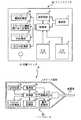
図4−1は、本実施の形態2にかかる手術システムの使用状態を示す模式図であって、図4−2は、実施の形態2にかかる手術システムを構成するハンドピースホルダの内部構造を示すブロック図である。図4−1に示すように、フットスイッチ1と、ハンドピース2に加えて、さらにハンドピースホルダ21を備えた構造を有する。なお、フットスイッチ1、ハンドピース2の構成、動作は以下で特に言及しない限り実施の形態1と同様のものとする。 FIG. 4A is a schematic diagram illustrating a usage state of the surgical system according to the second embodiment. FIG. 4B illustrates the internal structure of the handpiece holder that configures the surgical system according to the second embodiment. FIG. As shown in FIG. 4A, in addition to the foot switch 1 and the handpiece 2, the structure further includes a handpiece holder 21. The configurations and operations of the foot switch 1 and the hand piece 2 are the same as those in the first embodiment unless otherwise specified.
ハンドピースホルダ21は、不使用状態のハンドピース2を保持するための保持部材23a〜23dと、保持部材23a〜23dに保持されているハンドピース2のIDを読みとるID認識部22a〜22dとを備えた構造を有する。ID認識部22a〜22dは、例えばハンドピース2と無線交信を行うことによってIDに関する情報を得る構造としても良いが、本実施の形態2ではより簡易な構造として、ハンドピース2の表面上にバーコード等の識別シールを付し、ID認識部22a〜22dはかかる識別シールを読みとることによって保持されているハンドピース2のIDを認識することとする。なお、保持部材およびID認識部の個数は使用するハンドピース2の数によって決定されるため、4個に限定したものと解釈する必要はない。 The handpiece holder 21 includes holding
ハンドピースホルダ21の内部構造について図4−2を参照して説明する。図4−2に示すように、ハンドピースホルダ21の内部にはID認識部22a〜22dからの情報が入力されるハンドピース有無判別部24と、ハンドピース有無判別部24からの情報を記憶する記憶部25と、ハンドピース有無判別部24からの情報をフットスイッチ1に対して送信する送信部26とを有する。なお、本実施の形態2においてハンドピースホルダ21とフットスイッチ1とは無線交信によって情報のやりとりを行うこととするが、ワイヤで接続された構造としても良い。 The internal structure of the handpiece holder 21 will be described with reference to FIG. As shown in FIG. 4B, the handpiece holder 21 stores the information from the handpiece presence /
次に、本実施の形態2にかかる手術システムを構成するハンドピースホルダ21の動作について説明する。図5は、ハンドピースホルダ21の動作を示すフローチャートである。以下、図5を参照しつつハンドピースホルダ21の動作について、フットスイッチ1との関係を中心に説明する。 Next, operation | movement of the handpiece holder 21 which comprises the surgery system concerning this Embodiment 2 is demonstrated. FIG. 5 is a flowchart showing the operation of the handpiece holder 21. Hereinafter, the operation of the handpiece holder 21 will be described focusing on the relationship with the foot switch 1 with reference to FIG.
まず、すべてのハンドピース2が保持された状態で、ハンドピースホルダ21は、保持部材23a〜23dに保持されているハンドピース2のIDをID認識部22a〜22dによって認識した後、ハンドピース有無判別部24を介して記憶部25に入力し、認識したIDを記憶部25に記憶する(ステップS301)。本ステップにより、ハンドピースホルダ21では、使用される可能性のあるハンドピース2のIDをすべて認識したこととなる。 First, in a state where all the handpieces 2 are held, the handpiece holder 21 recognizes the ID of the handpiece 2 held by the holding
そして、一定時間経過後、保持部材23a〜23dに保持されているハンドピース2のIDをID認識部22a〜22dによって再び認識し(ステップS302)、ステップS302で新たに認識したデータと、ステップS301で記憶されたデータとを比較する(ステップS303)。具体的には、ステップS303では、ステップS301で認識したハンドピース2のIDと、ステップS302で認識したハンドピース2のIDとを比較し、ステップS301で認識したにもかかわらず、ステップS302で認識できなかったハンドピース2のIDに関する情報である差分データを生成する。 Then, after a certain period of time, the ID of the handpiece 2 held by the holding
その後、ハンドピースホルダ21は、生成した差分データを送信する(ステップS304)。フットスイッチ1は、差分データを受信し、差分データに基づいて使用可能なハンドピース2を認識する(ステップS305)。 Thereafter, the handpiece holder 21 transmits the generated difference data (step S304). The foot switch 1 receives the difference data, and recognizes the usable handpiece 2 based on the difference data (step S305).
上記のように、差分データに含まれるハンドピース2のIDは、初期状態において認識されたにもかかわらず、一定時間経過したステップS302において認識されなかったものである。ID認識部22は、保持部材23に保持されたハンドピース2のIDを認識することから、差分データに含まれるIDは、保持部材23による保持状態を脱したハンドピース、すなわち使用者がハンドピースホルダ21から取り出したハンドピースに対応することとなる。従って、ステップS304で送信される差分データは、使用者が取り出したハンドピースのIDを情報として含むこととなる。 As described above, the ID of the handpiece 2 included in the difference data is not recognized in step S302 after a certain period of time despite being recognized in the initial state. Since the ID recognition unit 22 recognizes the ID of the handpiece 2 held by the holding member 23, the ID included in the difference data is the handpiece that is released from the holding state by the holding member 23, that is, the user uses the handpiece. It corresponds to the handpiece taken out from the holder 21. Therefore, the difference data transmitted in step S304 includes the ID of the handpiece taken out by the user as information.
このため、例えば同時に単一のハンドピース2を使用するケースであれば、使用するハンドピース2のIDの認識を自動的に行うことが可能である。すなわち、使用するハンドピース2をハンドピースホルダ21から外すことによってハンドピースホルダ21からIDに関する情報がフットスイッチ1に伝達されることから、フットスイッチ1は、切替スイッチ10による選択を行わずに制御対象となるハンドピース2を認識することができる。 For this reason, for example, in the case of using a single handpiece 2 at the same time, it is possible to automatically recognize the ID of the handpiece 2 to be used. That is, by removing the handpiece 2 to be used from the handpiece holder 21, information about the ID is transmitted from the handpiece holder 21 to the foot switch 1, so that the foot switch 1 is controlled without performing selection by the changeover switch 10. The target handpiece 2 can be recognized.
また、同時に複数のハンドピースを使用する場合であっても、切替スイッチ10による切替の対象がハンドピースホルダ21から外されたハンドピース2に限定されるという利点を有する。選択候補の数が減少することによって、使用者の選択誤りの可能性を低減することができる。例えば、フットスイッチ1は、ハンドピースホルダ21から得たデータに含まれないハンドピース2のIDを発信データに含めることができない構造を採用すると良い。かかる構成とすることで、切替スイッチ10で誤ったハンドピース2を選択した場合であっても誤動作が生じることを防ぐことができる。 Further, even when a plurality of handpieces are used at the same time, there is an advantage that the object to be switched by the changeover switch 10 is limited to the handpiece 2 removed from the handpiece holder 21. By reducing the number of selection candidates, the possibility of user selection error can be reduced. For example, the foot switch 1 may adopt a structure in which the ID of the handpiece 2 that is not included in the data obtained from the handpiece holder 21 cannot be included in the transmission data. By adopting such a configuration, it is possible to prevent malfunction even when the wrong handpiece 2 is selected by the changeover switch 10.
(実施の形態3)
次に、実施の形態3にかかる手術システムについて説明する。本実施の形態3にかかる手術システムは、ハンドピースの構造として、電源部がハンドピース本体から着脱可能な構造を有し、かつ使用者が選択したハンドピースにのみ電源部を接続する構成としている。なお、本実施の形態3において、ハンドピース以外の構成要素に関しては以下で特に言及しない限り実施の形態1または実施の形態2と同様の構造を有し、同様の機能を果たすものとする。(Embodiment 3)
Next, a surgery system according to the third embodiment will be described. The operation system according to the third embodiment has a structure in which the power supply unit is detachable from the handpiece body as the structure of the handpiece, and the power supply unit is connected only to the handpiece selected by the user. . In the third embodiment, components other than the handpiece have the same structure as that of the first embodiment or the second embodiment and perform the same function unless otherwise specified below.
図6は、本実施の形態3にかかる手術システムを構成するハンドピース28の構造を示すブロック図である。図6に示すように、ハンドピース28は、実施の形態1または実施の形態2と異なり、ケース部材19の外部に独立電源部29を備えた構造を有し、ハンドピース28に設けられた接続部31と、独立電源部29とは接続ワイヤ30によって接続された構成を有する。接続ワイヤ30と接続部31との間は着脱可能な構造とし、独立電源部29は、機能の異なる任意のハンドピース28の電源部として使用可能な性能を有することとする。そして、本実施の形態3では、独立電源部29は使用時において、実際に使用するハンドピース28に対してのみ接続される構成とする。 FIG. 6 is a block diagram showing the structure of the handpiece 28 constituting the surgical system according to the third embodiment. As shown in FIG. 6, unlike the first or second embodiment, the handpiece 28 has a structure including an independent
また、本実施の形態3においては、ハンドピース28は処置部材12および接続部31を除いてケース部材19に覆われた構造を有し、独立電源部29も接続ワイヤ30との接続部分を除いて絶縁性のケース部材によって覆われた構造を有する。接続ワイヤ30に関しても、ハンドピース28および独立電源部29との接続部分を除いて絶縁部材によって覆われた構造を有する。従って、使用時においては、ハンドピース28等は処置部材12を除いて外部とは電気的に接触することのない構造を有する。 In the third embodiment, the handpiece 28 has a structure covered with the case member 19 except for the
さらに、本実施の形態3にかかる手術システムにおいて、独立電源部29の個数は、ハンドピース28の個数よりも少ないものとし、例えば、独立電源部29は、同時に使用するハンドピース28の数だけ備えることが好ましい。そして、実施の形態3にかかる手術システムでは、使用するハンドピース28を切り替えるごとに独立電源部29の接続先を切り替えて使用する。 Further, in the surgical system according to the third embodiment, the number of independent
次に、本実施の形態3にかかる手術システムの利点について説明する。まず、ハンドピース28の外部に独立電源部29を設ける構造としたことによる利点について説明する。 Next, advantages of the surgical system according to the third embodiment will be described. First, the advantage by having the structure which provided the independent
本実施の形態3にかかる手術システムは、独立電源部29をハンドピース28の外部に設けることで、独立電源部29の設計自由度が拡大するという利点を有する。すなわち、ハンドピース28は、使用者が携帯可能な構造とする必要があるため、ハンドピース28内に電源部を設けた場合には重量および大きさが制限される。しかし、本実施の形態3のように独立電源部29を外部に設けることによって、かかる制限を気にすることなく独立電源部29を設計することが可能であり、独立電源部29として、例えば大容量の構造を使用することが可能である。 The surgical system according to the third embodiment has an advantage that the degree of freedom in designing the independent
また、本実施の形態3にかかる手術システムでは、少なくとも使用時においては、ハンドピース28と独立電源部29とは接続ワイヤ30を介して接続されている。従って、ハンドピース28、独立電源部29および接続ワイヤ30を一体として考えた場合、処置部材12以外の部分が外部と電気的に接続することはない。従って、実施の形態1の場合と同様に、複数のハンドピース2を使用した場合であってもハンドピース間で高周波電流または低周波電流が漏電することはなく、実施の形態1と同様に安全対策としてトランス回路を設ける必要がないという利点を有する。 In the surgical system according to the third embodiment, at least during use, the handpiece 28 and the independent
また、独立電源部29の個数を、同時に使用するハンドピース28の個数と同数程度に限定することによる利点について説明する。かかる構成では、同時に使用するハンドピース28の分だけ独立電源部29を用意すれば足りるという消極的な利点のみならず、かかる個数に限定することによる積極的な利点も存在する。 Further, an advantage of limiting the number of independent
ハンドピース28は内部に電源部を備えず、接続ワイヤ30を介して独立電源部29と接続することによって初めて内部の送受信部15等が動作可能となる。従って、本実施の形態3では、現実に動作させるハンドピース28のみがフットスイッチ1からの発信データを受信することが可能である。このため、想定外のハンドピース28がフットスイッチ1からの発信データを受信して誤動作することは無く、誤動作の発生確率をさらに低減することが可能である。従って、例えば同時に動作するハンドピース28の個数を1とするシステムの場合には、複数のハンドピース28の中から1個のハンドピースを選択する構成とした場合であっても、ハンドピース28にIDを割り当てることなく誤動作の発生を防止することが可能となる。 The handpiece 28 does not include a power supply unit inside, and the internal transmission /
なお、本実施の形態3では、接続ワイヤ30を用いた構造を有することから、従来と同様にワイヤが多数存在することによって使用者等の室内移動や医療器具の搬入に対して影響を及ぼす懸念が存在する。本実施の形態3の場合にはかかる問題が発生しないことについて以下で説明する。 In the third embodiment, since the
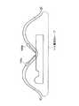
図7は、本実施の形態3にかかる手術システムの使用態様を示す図である。なお、図7の例では、同時に使用するハンドピース28の数が1の場合について示している。図7に示すように、実際に使用するハンドピース28aのみが接続ワイヤ30に接続されており、実施の形態3にかかる手術システムで必要となるワイヤの本数は1本のみである。さらに、本実施の形態3においてもフットスイッチ1とハンドピース28との間の情報の伝達は無線交信によって行われることから手術室の床にワイヤを這わせる必要はなく、例えば独立電源部29を点滴ポール32に吊すことで、接続ワイヤ30を空間上に配置した構成とすることが可能である。 FIG. 7 is a diagram illustrating how the surgical system according to the third embodiment is used. In the example of FIG. 7, the case where the number of handpieces 28 used simultaneously is 1 is shown. As shown in FIG. 7, only the handpiece 28a actually used is connected to the
従って、本実施の形態3においては、ワイヤの本数が従来に比較して少ないこと、ワイヤをフットスイッチ1に接続する必要がないことから床上に這わせたワイヤが存在しないこと等が理由となり、接続ワイヤ30を使用するにもかかわらず、従来のような問題が存在することはない。 Therefore, in the third embodiment, the number of wires is small as compared to the conventional case, and it is not necessary to connect the wires to the foot switch 1, and therefore there is no wire laid on the floor. Despite the use of the connecting
(実施の形態4)
次に、実施の形態4にかかる手術システムについて説明する。実施の形態4にかかる手術システムは、入力ペダルの機能の割り当てをフットスイッチ側で決定する構成を有する。従来の手術装置ではハンドピース側であらかじめ入力ペダルの割り当てが決定されていたのに対して、本実施の形態4にかかる手術システムでは使用者の好みや、複数のハンドピース間における動作の共通性に注目した入力ペダルの機能の割り当てが可能となる。(Embodiment 4)
Next, a surgery system according to
図8は、本実施の形態4にかかる手術システムの構成を示すブロック図である。図8に示すように、本実施の形態4にかかる手術システムは、フットスイッチ34と、ハンドピース35とを備えた構成を有する。なお、本実施の形態4にかかる手術システムは、フットスイッチ34および/またはハンドピース35を複数備えた構成を前提とするが、図8では簡潔にそれぞれが単数の例を図示している。 FIG. 8 is a block diagram illustrating a configuration of the surgical operation system according to the fourth embodiment. As shown in FIG. 8, the surgical system according to the fourth embodiment has a configuration including a foot switch 34 and a
フットスイッチ34は、入力ペダル3、4と、制御部5と、送受信部6と、電源部7と、ハンドピースID記憶部8と、自己ID記憶部9と、切替スイッチ10を有する。これらの要素の構成、機能は実施の形態1〜3と同様であるため、本実施の形態4では説明を省略する。 The foot switch 34 includes
さらに、フットスイッチ34は、ハンドピース動作記憶部36と、入力ペダル機能割り当て記憶部37とを備える。ハンドピース動作記憶部36は、IDが登録されたハンドピース35で実行可能な動作を記憶するためのものであり、入力ペダル機能割り当て記憶部37は、入力ペダルに割り当てられた機能を記憶するためのものである。 Further, the foot switch 34 includes a handpiece
本実施の形態4では、フットスイッチ34に備わった制御部5は、入力ペダル3または入力ペダル4の選択と、入力ペダル機能割り当て記憶部37に記憶した情報に基づいてハンドピース35に対して"output"を決定する構成を有する。例えば、ハンドピース35が超音波ハンドピースとしての機能を有する場合、ハンドピース35は患部に対して切開または凝固の作用を施すことが可能である。かかる2通りの動作と入力ペダル3、4との対応関係が入力ペダル機能割り当て記憶部37に記憶されており、制御部5は、かかる対応関係を参照しつつ送受信部6に指示を与え、所定の“output”を発信させている。 In the fourth embodiment, the control unit 5 provided in the foot switch 34 selects the
一方、ハンドピース35は、処置部材12と、駆動部13と、制御部14と、送受信部15と、電源部16と、フットスイッチID記憶部17との他に、動作記憶部38を備えた構成を有する。動作記憶部38は、処置部材12によって可能な動作の内容を記憶するためのものである。 On the other hand, the
次に、実施の形態4にかかる手術システムにおいて、フットスイッチ34に設けられた入力ペダル3、4の機能の割り当てプロセスについて、ID登録作業に伴って行う例について説明する。以下では、フットスイッチ34におけるハンドピース35の登録の際に併せて入力ペダル3、4の機能の割り当てを行う例について説明する。なお、ハンドピース35の登録プロセスについては実施の形態1とほぼ同様であるため、以下では簡潔に解説する。図9は、機能の割り当てプロセスを説明するためのフローチャートであって、以下図9を参照して説明を行う。 Next, in the surgery system according to the fourth embodiment, an example of performing the function assignment process of the
まず、フットスイッチ34は、自己のIDである“ID[FSWX]”を発信し(ステップS401)、ハンドピース35によって受信される(ステップS402)。ハンドピース35において“ID[FSWX]”を登録するか否かを判定し(ステップS403)、登録する場合にはフットスイッチID記憶部17に“ID[FSWX]”を記憶する(ステップS404)。 First, the foot switch 34 transmits its own ID “ID [FSWX]” (step S401) and is received by the handpiece 35 (step S402). It is determined whether or not “ID [FSWX]” is registered in the handpiece 35 (step S403), and in the case of registration, “ID [FSWX]” is stored in the foot switch ID storage unit 17 (step S404).
そして、ハンドピース35は、自己のIDである“ID[HPY]”と、登録した“ID[FSWX]”と、処置部材12で可能な動作に関する情報“function1”、“function2”とを含むデータを制御部14で生成し、発信する(ステップS405)。ここで、可能な動作に関する情報を2通りとしたのは、通常フットスイッチが有する入力ペダルの個数が2個であることに対応している。 The
その後、ステップS405で発信されたデータがフットスイッチ34で受信され、受信したデータの中に“ID[FSWX]”が含まれるか否かを判定し(ステップS406)、存在する場合には“ID[HPY]”を登録するか否かを判定する(ステップS407)。そして、“ID[HPY]”を登録すると判定した場合にはハンドピースID記憶部9に“ID[HPY]”を記憶する(ステップS408)。 Thereafter, the data transmitted in step S405 is received by the foot switch 34, and it is determined whether or not “ID [FSWX]” is included in the received data (step S406). It is determined whether or not [HPY] "is registered (step S407). When it is determined that “ID [HPY]” is registered, “ID [HPY]” is stored in the handpiece ID storage unit 9 (step S408).
そして、フットスイッチ34は、登録したハンドピース35が行う動作について、入力ペダル3、4への割り当てを行う。具体的には、ステップS405において発信された“function1”、“function2”に関する情報に基づいて、“function1”、“function2”と入力ペダル3、4との対応関係を決定する(ステップS409)。対応関係の決定手法としては、使用者の指示に従って決定することとしても良いし、後述する所定の条件に従って自動的に対応関係を決定することとしても良い。 Then, the foot switch 34 assigns the registered
その後、フットスイッチ34は、ステップS409で決定した対応関係を入力ペダル機能割り当て記憶部37に記憶する(ステップS410)。具体的には、ハンドピースID記憶部8に記憶されるIDと、function1”、“function2”と入力ペダル3、4との対応関係とが関連づけられた状態で入力ペダル機能割り当て記憶部37に記憶され、フットスイッチ34の使用時には、動作対象となるハンドピース35のIDに関連づけられた対応関係が入力ペダル機能割り当て記憶部37から抽出される。 Thereafter, the foot switch 34 stores the correspondence determined in step S409 in the input pedal function assignment storage unit 37 (step S410). Specifically, the ID stored in the handpiece
以後のプロセスは実施の形態1で説明した登録プロセスと同様である。すなわち、フットスイッチ34は、自己のIDである“ID[FSWX]”と、登録したハンドピース35のIDである“ID[HPY]”とに基づいて、“ID[FSWX]+ID[HPY]+received”を発信し(ステップS411)、“ID[HPY]”の登録を完了する(ステップS412)。そして、すべてのハンドピース35のIDの登録およびハンドピース35の機能の入力ペダルへの割り当てが完了したか否かを判定し(ステップS413)、完了していればフットスイッチ34側のすべての処理を終了する。 The subsequent process is the same as the registration process described in the first embodiment. That is, the foot switch 34 receives “ID [FSWX] + ID [HPY] + received” based on “ID [FSWX]” that is its own ID and “ID [HPY]” that is the ID of the registered
一方、ハンドピース35は、ステップS411においてフットスイッチ34から発信されたデータを受信し、受信したデータの中に“ID[HPY]”に関する情報が含まれるか否かを判定し(ステップS414)、含まれている場合には“ID[FSWX]”の登録を完了する(ステップS415)。そして、すべてのフットスイッチ34の登録が完了したか否かを判定し(ステップS416)、完了した場合はハンドピース35側のすべての処理を終了する。以上の登録プロセスを経ることによって、ハンドピース35側であらかじめ設定されていた入力ペダルとの対応関係をフットスイッチ34側で設定し直すことが可能となる。従って、使用者の好み等に合わせた対応関係の構築が可能となり、入力ペダルの誤選択等の発生頻度を低減することが可能となる。 On the other hand, the
次に、ステップS409における対応関係の決定条件の例について説明する。実施の形態4にかかる手術システムは、基本的に複数のハンドピース35を備えた構成となっているが、複数のハンドピース35の例として、例えば、超音波ハンドピース、電気メス等が存在する。これらのハンドピースは異なる機能を実現するものであるが、動作に一定の共通性を有することが知られている。その一方で、従来のハンドピース35の動作と、フットスイッチ34が備える入力ペダル3、4との対応関係はハンドピース35側で個別に決定されているため、動作が共通性を有するにも関わらず、共通する動作が一方のハンドピースでは入力ペダル3と対応し、他方のハンドピースでは入力ペダル4と対応するといった事態が存在した。かかる相違に基づいて使用者が入力ペダルの誤選択を行うおそれがあるため、ハンドピース35の動作と入力ペダル3、4との対応関係に共通性を持たせることが好ましい。 Next, an example of the correspondence determination condition in step S409 will be described. The surgical operation system according to the fourth embodiment basically includes a plurality of
複数のハンドピース35の種類として、最大出力による切開動作と、最大出力未満の所定出力による切開動作が可能な電気メスと、切開動作と、患部を凝固させる凝固動作とが可能な超音波ハンドピースAと、凝固動作と、送水動作が可能な超音波ハンドピースBとを備えた手術システムを想定する。電気メスと超音波ハンドピースAは、いずれも切開動作が可能な点で共通性を有する一方、超音波ハンドピースA、Bはいずれも凝固動作が可能な点で共通性を有する。従って、電気メス、超音波ハンドピースAおよび超音波ハンドピースBを備えた手術システムを構成する場合、かかる共通性を有する動作については、入力ペダル3、4への割り当てを統一することが好ましい。 As the types of the plurality of
仮に電気メスに関して、最大出力の切開動作が入力ペダル3に対応づけられ、所定出力による切開動作が入力ペダル4に対応づけられているとする。かかる前提の下、超音波ハンドピースA、Bの動作と入力ペダル3、4との対応関係を決定する場合には、例えば超音波ハンドピースAに関しては、切開動作を入力ペダル3に対応させ、凝固動作を入力ペダル4に対応させることが考えられる。そして、超音波ハンドピースBに関しては、超音波ハンドピースAと共通性を持たせる目的で凝固動作を入力ペダル4に対応させ、送水動作を入力ペダル3に対応させることが好ましい。かかる対応関係の決定により、少なくとも凝固動作に関しては同一の入力ペダル4によって動作させることとなるため、使用者が誤って入力ペダルを選択することを防止することができる。このように、複数の異なるハンドピースに関して、共通性を有する動作に関しては同一の入力ペダルと対応させることによって、使用者が入力ペダルを誤選択することを防止できる。上記以外の例としては、例えばハンドピースごとに実現する2通りの動作が、それぞれ単一の動作であって、処置部材12の動作強度のみが相違する構造の場合、複数のハンドピースに関して、入力ペダル3を選択した場合に最大出力の動作を行い、入力ペダル4を選択した場合に設定出力の動作(例えば、最大出力の1/2)を行うこととしても良い。さらに、入力ペダルを踏む回数によって処置部材12の動作強度が変化する場合、例えば入力ペダルを1回踏むと最大出力の20%、2回踏むと最大出力の40%、・・・となる場合には、かかる動作強度を調整する入力ペダルを入力ペダル3、4のいずれか一方に統一することとしても良い。 For the electric knife, it is assumed that the cutting operation with the maximum output is associated with the
さらに、本実施の形態4において、フットスイッチから発信する無線信号の内容をハンドピースごとに異なるものとしても良い。すなわち、フットスイッチから発信する無線信号のうち、“output”に対応する内容については、通常は入力ペダル3、4のいずれかに対応した信号を発信することとしている。そして、受信したハンドピース側に設けられた制御部によっていずれの入力ペダルに対応した信号であるかを解釈した上で、フットスイッチで選択された入力ペダルに対応する機能を実現するよう制御部から駆動部に指示を出すのが一般的である。しかしながら、実施の形態4では、“output”の内容をハンドピースごとに異ならせることによって、誤動作の発生を防止することとしても良い。ハンドピースごとに“output”の内容を異なることとした場合、フットスイッチ1が誤って選択したハンドピースと異なるハンドピースのIDを出力した場合であっても、間違ったハンドピースが解釈不能な“output”を受信することとなるため、間違ったハンドピースが動作することを防止することが可能となる。 Further, in the fourth embodiment, the content of the radio signal transmitted from the foot switch may be different for each handpiece. That is, among the radio signals transmitted from the foot switch, the content corresponding to “output” is normally transmitted as a signal corresponding to one of the
以上、実施の形態1〜4に渡って本発明を説明してきたが、本発明は上記のものに限定されず、当業者であれば様々な実施例、変形例および応用例に想到することが可能である。例えば、実施の形態1〜4について、遠隔操作装置の例としてフットスイッチを用いているが、入力ペダルを使用者が足で踏む構造以外の構造も可能である。また、入力ペダルの数についても単数でもよいし、3以上の複数としても良い。さらには、フットスイッチおよびハンドピースの機能ブロックについても、実施の形態1〜4で説明したものと異なる構成とすることも可能である。 As described above, the present invention has been described over the first to fourth embodiments. However, the present invention is not limited to the above-described ones, and those skilled in the art can conceive various examples, modifications, and application examples. Is possible. For example, in Embodiments 1 to 4, a foot switch is used as an example of a remote control device, but a structure other than a structure in which the user steps on the input pedal with a foot is also possible. Further, the number of input pedals may be singular or may be three or more. Furthermore, the functional blocks of the foot switch and the handpiece can be configured differently from those described in the first to fourth embodiments.
1 フットスイッチ
2 ハンドピース
3、4 入力ペダル
5 制御部
6 送受信部
7 電源部
8 ハンドピースID記憶部
9 自己ID記憶部
10 切替スイッチ
12 処置部材
13 駆動部
14 制御部
15 送受信部
16 電源部
17 フットスイッチID記憶部
18 自己ID記憶部
19 ケース部材
21 ハンドピースホルダ
22 ID認識部
23 保持部材
24 ハンドピース有無判別部
25 記憶部
26 送信部
28 ハンドピース
29 独立電源部
30 接続ワイヤ
31 接続部
32 点滴ポール
34 フットスイッチ
35 ハンドピース
36 ハンドピース動作記憶部
37 入力ペダル機能割り当て記憶部
38 動作記憶部
101 ハンドピース
102 ワイヤ
103 本体装置
104 ワイヤ
105 フットスイッチ
106、107 入力ペダル
108 ハンドピース
109 本体装置
110 フットスイッチ
111 電気的ループDESCRIPTION OF SYMBOLS 1 Foot switch 2
Claims (8)
Translated fromJapanese前記遠隔操作装置は、
当該遠隔操作装置に割り当てられた操作装置識別情報を記憶する第1記憶手段と、
当該遠隔操作装置と対応付けられた前記携帯型処置装置に割り当てられた処置装置識別情報を記憶する第2記憶手段と、
前記携帯型処置装置の動作内容を入力する入力手段と、
前記携帯型処置装置との間で無線交信を行う操作装置側交信手段と、
前記操作装置側交信手段を介して前記携帯型処置装置へ前記操作装置識別情報と前記処置装置識別情報と前記動作内容とを含む操作情報を送信する操作情報送信手段と、
を有し、
前記携帯型処置装置は、
前記所定の処置を実行する処置部と、
前記処置部に駆動エネルギーを供給する駆動手段と、
前記処置装置識別情報を記憶する第3記憶手段と、
前記操作装置識別情報を記憶する第4記憶手段と、
前記遠隔操作装置との間で無線交信を行う処置装置側交信手段と、
前記処置装置側交信手段を介して前記遠隔操作装置から入力された前記操作情報に前記第3記憶手段に記憶されている前記処置装置識別情報および前記第4記憶手段に記憶されている前記操作装置識別情報が含まれているか否かを判定する判定手段と、
前記判定手段による判定の結果、前記操作情報に前記第3記憶手段に記憶されている前記処置装置識別情報および前記第4記憶手段に記憶されている前記操作装置識別情報が含まれている場合、前記操作情報に含まれている前記動作内容に従って前記駆動手段が前記処置部へ供給する駆動エネルギーを増減する駆動エネルギー制御手段と、
当該携帯型処置装置の外壁を形成し、前記処置部の少なくとも一部を前記処置対象に対して露出可能な絶縁性のケース部材と、
を有することを特徴とする手術システム。A portable treatmentapparatus for executing a predetermined treatment in the treatment target, in a surgical system anda remote control device for performing remote operations on the portable treatment apparatus,
The remote control device is:
First storage means for storing operating device identification information assigned to the remote control device;
Second storage means for storing treatment device identification information assigned to the portable treatment device associated with the remote control device;
Input means for inputting the operation content of the portable treatment apparatus;
Operation device side communication means for performing wireless communication with the portable treatment device;
Operation information transmission means for transmitting operation information including the operation device identification information, the treatment device identification information, and the operation content to the portable treatment device via the operation device side communication means;
Have
The portable treatment device comprises:
A treatment unit for performing the predetermined treatment;
Drive means for supplying drive energy to the treatment section;
Third storage means for storing the treatment device identification information;
Fourth storage means for storing the operating device identification information;
Treatment device side communication means for performing wireless communication with the remote control device;
The operation information input from the remote operation device via the treatment device side communication means, the treatment device identification information stored in the third storage means, and the operation device stored in the fourth storage means Determining means for determining whether or not identification information is included;
As a result of determination by the determination unit, when the operation information includes the treatment device identification information stored in the third storage unit and the operation device identification information stored in the fourth storage unit, Drive energy control means for increasing or decreasing the drive energy supplied to the treatment unit by the drive means according to the operation content included in the operation information;
Forming an outer wall of the portable treatment device, an insulating case membercapable of exposing at least a part of the treatment portion to the treatment target;
Surgical system characterized byhaving a.
前記操作情報送信手段は、前記操作装置側交信手段を介して前記携帯型処置装置へ前記操作装置識別情報と前記処置装置識別情報とを含むスタンバイモード解除情報を送信し、
前記判定手段は、前記処置装置側交信手段を介して前記遠隔操作装置から入力された前記スタンバイモード解除情報に前記第3記憶手段に記憶されている前記処置装置識別情報および前記第4記憶手段に記憶されている前記操作装置識別情報が含まれているか否かを判定し、
前記携帯型処置装置は、前記判定手段による判定の結果、前記スタンバイモード解除情報に前記第3記憶手段に記憶されている前記処置装置識別情報および前記第4記憶手段に記憶されている前記操作装置識別情報が含まれている場合、前記スタンバイモードから前記レディモードに移行することを特徴とする請求項1に記載の手術システム。The portable treatment device hasat least a standby mode in which the treatment device side communication means is kept in an on stateand at least the drive means is kept in an off state, andat least the treatment device side communication means and the drive means are in an on state. has a ready mode tomaintain,the,
The operation information transmission means transmits standby mode release information including the operation apparatus identification information and the treatment apparatus identification information to the portable treatment apparatus via the operation apparatus side communication means,
The determination means includes the treatment apparatus identification information stored in the third storage means and the fourth storage means in the standby mode release information input from the remote control device via the treatment apparatus side communication means. It is determined whether or not the stored operation device identification information is included,
In the portable treatment device, as a result of the determination by the determination unit, the treatment device identification information stored in the third storage unit as the standby mode release information and the operation device stored in the fourth storage unit if it contains identification information, surgical system according to claim1, characterized in that the transition from the standby mode to the ready mode.
前記保持部に保持された1つ以上の携帯型処置装置の処置装置識別情報をそれぞれ検知する情報検知手段と、
前記情報検知手段で検出した前記1つ以上の処置装置識別情報を記憶する第5記憶手段と、
前記第5記憶手段に記憶された処理装置識別情報のうち前記情報検知手段で検知不能となった処置装置識別情報を含む保持情報を前記遠隔操作装置側に送信する送信手段と、
を有する保持装置をさらに備えたことを特徴とする請求項1〜3のいずれか一つに記載の手術システム。Ahold portionyoudetachably holding a plurality of the portable treatment apparatus,
Information detectionmeans for detecting atreatment device identificationinformation ofone or more portable treatment apparatus which is held bythe holdingportions, respectively,
Fifth storage means for storing the one or more treatment device identification information detected by the information detection means;
Transmittingmeans for transmitting to the remote control device sideholding information includingtreatment device identificationinformation that cannotbe detected by theinformation detectionmeansamong the processing device identification information stored in the fifth storage means ;
The surgical operation system according to any one of claims 1 to3 , further comprising a holding device having:
前記複数の携帯型処置装置それぞれに着脱可能であって該複数の携帯型処置装置それぞれに対して電力を供給可能な電源部と、
を備え、
前記遠隔操作装置は、前記電源部が接続された前記携帯型処置装置を選択して遠隔操作することを特徴とする請求項1〜5のいずれか一つに記載の手術システム。A plurality of the portable treatment devices;
A power supply unit capable of supplying power to eachof the plurality of portable treatment apparatusbe detachable to each of the plurality of portable treatment apparatus,
With
The remote control device, surgical system according to any one of claims1-5, characterized inthat theremote control to selectthe portable treatmentequipment that thepower supply unit is connected.
Priority Applications (1)
| Application Number | Priority Date | Filing Date | Title |
|---|---|---|---|
| JP2004105204AJP4328254B2 (en) | 2004-03-31 | 2004-03-31 | Surgery system |
Applications Claiming Priority (1)
| Application Number | Priority Date | Filing Date | Title |
|---|---|---|---|
| JP2004105204AJP4328254B2 (en) | 2004-03-31 | 2004-03-31 | Surgery system |
Publications (2)
| Publication Number | Publication Date |
|---|---|
| JP2005287684A JP2005287684A (en) | 2005-10-20 |
| JP4328254B2true JP4328254B2 (en) | 2009-09-09 |
Family
ID=35321297
Family Applications (1)
| Application Number | Title | Priority Date | Filing Date |
|---|---|---|---|
| JP2004105204AExpired - Fee RelatedJP4328254B2 (en) | 2004-03-31 | 2004-03-31 | Surgery system |
Country Status (1)
| Country | Link |
|---|---|
| JP (1) | JP4328254B2 (en) |
Cited By (1)
| Publication number | Priority date | Publication date | Assignee | Title |
|---|---|---|---|---|
| JP2013184032A (en)* | 2012-03-12 | 2013-09-19 | Osada Res Inst Ltd | Dental treatment instrument |
Families Citing this family (4)
| Publication number | Priority date | Publication date | Assignee | Title |
|---|---|---|---|---|
| CA2803828C (en)* | 2005-03-31 | 2015-11-24 | Alcon, Inc. | Footswitch operable to control a surgical system |
| DE102008024438A1 (en)* | 2008-05-14 | 2009-11-19 | Aesculap Ag | Surgical drive unit, surgical instrument and surgical drive system |
| GB2594509B (en)* | 2020-04-30 | 2024-04-10 | Gyrus Medical Ltd | Electrosurgical system with customised control |
| JP7412667B1 (en) | 2023-02-22 | 2024-01-15 | 株式会社創和イノベーション | Beauty Equipment |
Family Cites Families (9)
| Publication number | Priority date | Publication date | Assignee | Title |
|---|---|---|---|---|
| JPS5883949A (en)* | 1981-11-12 | 1983-05-19 | オリンパス光学工業株式会社 | Drill apparatus for treating body cavity |
| NO165661C (en)* | 1984-12-11 | 1991-03-20 | Valleylab Inc | ELECTRO-SURGICAL GENERATION SYSTEM. |
| JPS635701Y2 (en)* | 1985-06-20 | 1988-02-17 | ||
| US5249121A (en)* | 1989-10-27 | 1993-09-28 | American Cyanamid Company | Remote control console for surgical control system |
| JP3386191B2 (en)* | 1992-08-19 | 2003-03-17 | オリンパス光学工業株式会社 | Surgical equipment control system |
| JP3223042B2 (en)* | 1994-06-23 | 2001-10-29 | 株式会社モリタ製作所 | Dental treatment device with cordless handpiece and root canal length measurement function |
| JP2000287986A (en)* | 1999-04-01 | 2000-10-17 | Olympus Optical Co Ltd | Tool for surgical implement |
| JP2002306504A (en)* | 2001-04-18 | 2002-10-22 | Olympus Optical Co Ltd | Surgical system |
| JP2003275221A (en)* | 2002-03-20 | 2003-09-30 | Olympus Optical Co Ltd | Controller device |
- 2004
- 2004-03-31JPJP2004105204Apatent/JP4328254B2/ennot_activeExpired - Fee Related
Cited By (1)
| Publication number | Priority date | Publication date | Assignee | Title |
|---|---|---|---|---|
| JP2013184032A (en)* | 2012-03-12 | 2013-09-19 | Osada Res Inst Ltd | Dental treatment instrument |
Also Published As
| Publication number | Publication date |
|---|---|
| JP2005287684A (en) | 2005-10-20 |
Similar Documents
| Publication | Publication Date | Title |
|---|---|---|
| US11147611B2 (en) | Relay device and ultrasonic-surgical and electrosurgical system | |
| JP3905482B2 (en) | Surgery system | |
| EP2301461B1 (en) | Apparatus for smart handset design in surgical instruments | |
| US7353068B2 (en) | Control device for a medical system and control method for medical system | |
| US7749240B2 (en) | Ultrasonic surgical system | |
| JP5763245B2 (en) | Surgical tool system that includes a tool and a console, and the console can read data from a memory integrated with the tool using a conductor that powers the tool | |
| JP5409988B2 (en) | Enhanced electrosurgical instrument | |
| JP4451459B2 (en) | Relay unit and operation system for ultrasonic surgical apparatus and high-frequency ablation apparatus | |
| US6551312B2 (en) | Wireless electrosurgical device and methods thereof | |
| JP2002306504A (en) | Surgical system | |
| JPWO2004030563A1 (en) | Surgery system | |
| KR20150003309A (en) | Control circuit of a surgical device with a switch and a method for determining the state of the switch | |
| JP2006081664A (en) | Medical system and method for controlling medical system | |
| CN104349731A (en) | Surgical instrument with orientation sensing | |
| JP4328254B2 (en) | Surgery system | |
| JP2006187668A (en) | Operation system | |
| JP2004113805A (en) | Control method for surgery system | |
| JP4037650B2 (en) | Dental treatment equipment | |
| JP2000271135A (en) | Ultrasonosurgery system | |
| JP2007319697A (en) | Control device for medical system | |
| JP4040914B2 (en) | Ultrasonic surgical device | |
| JP2001293005A (en) | Device for energy endo-therapy accessories energy treating device equipment | |
| US12354457B2 (en) | Surgical device system, method of operating the same, and wireless license tag | |
| JP4217216B2 (en) | Electrosurgical system | |
| US20050187539A1 (en) | Electric operation system |
Legal Events
| Date | Code | Title | Description |
|---|---|---|---|
| A621 | Written request for application examination | Free format text:JAPANESE INTERMEDIATE CODE: A621 Effective date:20070117 | |
| A977 | Report on retrieval | Free format text:JAPANESE INTERMEDIATE CODE: A971007 Effective date:20080904 | |
| A131 | Notification of reasons for refusal | Free format text:JAPANESE INTERMEDIATE CODE: A131 Effective date:20080916 | |
| A521 | Request for written amendment filed | Free format text:JAPANESE INTERMEDIATE CODE: A523 Effective date:20081104 | |
| TRDD | Decision of grant or rejection written | ||
| A01 | Written decision to grant a patent or to grant a registration (utility model) | Free format text:JAPANESE INTERMEDIATE CODE: A01 Effective date:20090519 | |
| A01 | Written decision to grant a patent or to grant a registration (utility model) | Free format text:JAPANESE INTERMEDIATE CODE: A01 | |
| A61 | First payment of annual fees (during grant procedure) | Free format text:JAPANESE INTERMEDIATE CODE: A61 Effective date:20090612 | |
| FPAY | Renewal fee payment (event date is renewal date of database) | Free format text:PAYMENT UNTIL: 20120619 Year of fee payment:3 | |
| R151 | Written notification of patent or utility model registration | Ref document number:4328254 Country of ref document:JP Free format text:JAPANESE INTERMEDIATE CODE: R151 | |
| FPAY | Renewal fee payment (event date is renewal date of database) | Free format text:PAYMENT UNTIL: 20120619 Year of fee payment:3 | |
| FPAY | Renewal fee payment (event date is renewal date of database) | Free format text:PAYMENT UNTIL: 20120619 Year of fee payment:3 | |
| FPAY | Renewal fee payment (event date is renewal date of database) | Free format text:PAYMENT UNTIL: 20130619 Year of fee payment:4 | |
| S531 | Written request for registration of change of domicile | Free format text:JAPANESE INTERMEDIATE CODE: R313531 | |
| R350 | Written notification of registration of transfer | Free format text:JAPANESE INTERMEDIATE CODE: R350 | |
| R250 | Receipt of annual fees | Free format text:JAPANESE INTERMEDIATE CODE: R250 | |
| R250 | Receipt of annual fees | Free format text:JAPANESE INTERMEDIATE CODE: R250 | |
| R250 | Receipt of annual fees | Free format text:JAPANESE INTERMEDIATE CODE: R250 | |
| LAPS | Cancellation because of no payment of annual fees |