JP4326185B2 - Tightening device - Google Patents
Tightening deviceDownload PDFInfo
- Publication number
- JP4326185B2 JP4326185B2JP2002106927AJP2002106927AJP4326185B2JP 4326185 B2JP4326185 B2JP 4326185B2JP 2002106927 AJP2002106927 AJP 2002106927AJP 2002106927 AJP2002106927 AJP 2002106927AJP 4326185 B2JP4326185 B2JP 4326185B2
- Authority
- JP
- Japan
- Prior art keywords
- clamping
- opening
- central bore
- threaded shaft
- bore
- Prior art date
- Legal status (The legal status is an assumption and is not a legal conclusion. Google has not performed a legal analysis and makes no representation as to the accuracy of the status listed.)
- Expired - Fee Related
Links
- 230000003628erosive effectEffects0.000abstractdescription6
- 238000000034methodMethods0.000description1
Images


Classifications
- B—PERFORMING OPERATIONS; TRANSPORTING
- B25—HAND TOOLS; PORTABLE POWER-DRIVEN TOOLS; MANIPULATORS
- B25B—TOOLS OR BENCH DEVICES NOT OTHERWISE PROVIDED FOR, FOR FASTENING, CONNECTING, DISENGAGING OR HOLDING
- B25B15/00—Screwdrivers
- B—PERFORMING OPERATIONS; TRANSPORTING
- B23—MACHINE TOOLS; METAL-WORKING NOT OTHERWISE PROVIDED FOR
- B23H—WORKING OF METAL BY THE ACTION OF A HIGH CONCENTRATION OF ELECTRIC CURRENT ON A WORKPIECE USING AN ELECTRODE WHICH TAKES THE PLACE OF A TOOL; SUCH WORKING COMBINED WITH OTHER FORMS OF WORKING OF METAL
- B23H7/00—Processes or apparatus applicable to both electrical discharge machining and electrochemical machining
- B23H7/26—Apparatus for moving or positioning electrode relatively to workpiece; Mounting of electrode
- B23H7/265—Mounting of one or more thin electrodes
- B—PERFORMING OPERATIONS; TRANSPORTING
- B23—MACHINE TOOLS; METAL-WORKING NOT OTHERWISE PROVIDED FOR
- B23H—WORKING OF METAL BY THE ACTION OF A HIGH CONCENTRATION OF ELECTRIC CURRENT ON A WORKPIECE USING AN ELECTRODE WHICH TAKES THE PLACE OF A TOOL; SUCH WORKING COMBINED WITH OTHER FORMS OF WORKING OF METAL
- B23H9/00—Machining specially adapted for treating particular metal objects or for obtaining special effects or results on metal objects
- B23H9/003—Making screw-threads or gears
- B—PERFORMING OPERATIONS; TRANSPORTING
- B25—HAND TOOLS; PORTABLE POWER-DRIVEN TOOLS; MANIPULATORS
- B25B—TOOLS OR BENCH DEVICES NOT OTHERWISE PROVIDED FOR, FOR FASTENING, CONNECTING, DISENGAGING OR HOLDING
- B25B5/00—Clamps
- B25B5/14—Clamps for work of special profile
- B25B5/147—Clamps for work of special profile for pipes
- F—MECHANICAL ENGINEERING; LIGHTING; HEATING; WEAPONS; BLASTING
- F16—ENGINEERING ELEMENTS AND UNITS; GENERAL MEASURES FOR PRODUCING AND MAINTAINING EFFECTIVE FUNCTIONING OF MACHINES OR INSTALLATIONS; THERMAL INSULATION IN GENERAL
- F16B—DEVICES FOR FASTENING OR SECURING CONSTRUCTIONAL ELEMENTS OR MACHINE PARTS TOGETHER, e.g. NAILS, BOLTS, CIRCLIPS, CLAMPS, CLIPS OR WEDGES; JOINTS OR JOINTING
- F16B37/00—Nuts or like thread-engaging members
- F16B37/08—Quickly-detachable or mountable nuts, e.g. consisting of two or more parts; Nuts movable along the bolt after tilting the nut
- F16B37/0807—Nuts engaged from the end of the bolt, e.g. axially slidable nuts
- F16B37/0864—Nuts engaged from the end of the bolt, e.g. axially slidable nuts with the threaded portions of the nut engaging the thread of the bolt by pressing or rotating an external retaining member such as a cap, a nut, a ring or a sleeve
- Y—GENERAL TAGGING OF NEW TECHNOLOGICAL DEVELOPMENTS; GENERAL TAGGING OF CROSS-SECTIONAL TECHNOLOGIES SPANNING OVER SEVERAL SECTIONS OF THE IPC; TECHNICAL SUBJECTS COVERED BY FORMER USPC CROSS-REFERENCE ART COLLECTIONS [XRACs] AND DIGESTS
- Y10—TECHNICAL SUBJECTS COVERED BY FORMER USPC
- Y10T—TECHNICAL SUBJECTS COVERED BY FORMER US CLASSIFICATION
- Y10T403/00—Joints and connections
- Y10T403/59—Manually releaseable latch type
- Y10T403/591—Manually releaseable latch type having operating mechanism
- Y—GENERAL TAGGING OF NEW TECHNOLOGICAL DEVELOPMENTS; GENERAL TAGGING OF CROSS-SECTIONAL TECHNOLOGIES SPANNING OVER SEVERAL SECTIONS OF THE IPC; TECHNICAL SUBJECTS COVERED BY FORMER USPC CROSS-REFERENCE ART COLLECTIONS [XRACs] AND DIGESTS
- Y10—TECHNICAL SUBJECTS COVERED BY FORMER USPC
- Y10T—TECHNICAL SUBJECTS COVERED BY FORMER US CLASSIFICATION
- Y10T403/00—Joints and connections
- Y10T403/59—Manually releaseable latch type
- Y10T403/598—Transversely sliding pin
- Y—GENERAL TAGGING OF NEW TECHNOLOGICAL DEVELOPMENTS; GENERAL TAGGING OF CROSS-SECTIONAL TECHNOLOGIES SPANNING OVER SEVERAL SECTIONS OF THE IPC; TECHNICAL SUBJECTS COVERED BY FORMER USPC CROSS-REFERENCE ART COLLECTIONS [XRACs] AND DIGESTS
- Y10—TECHNICAL SUBJECTS COVERED BY FORMER USPC
- Y10T—TECHNICAL SUBJECTS COVERED BY FORMER US CLASSIFICATION
- Y10T403/00—Joints and connections
- Y10T403/70—Interfitted members
- Y10T403/7062—Clamped members
- Y10T403/7064—Clamped members by wedge or cam
- Y10T403/7066—Clamped members by wedge or cam having actuator
- Y10T403/7067—Threaded actuator
- Y10T403/7069—Axially oriented
Landscapes
- Engineering & Computer Science (AREA)
- Mechanical Engineering (AREA)
- Chemical & Material Sciences (AREA)
- Chemical Kinetics & Catalysis (AREA)
- Electrochemistry (AREA)
- Thermal Sciences (AREA)
- Physics & Mathematics (AREA)
- Clamps And Clips (AREA)
- Electrical Discharge Machining, Electrochemical Machining, And Combined Machining (AREA)
- Furnace Details (AREA)
- Jigs For Machine Tools (AREA)
- Manipulator (AREA)
- Sampling And Sample Adjustment (AREA)
- Physical Vapour Deposition (AREA)
Abstract
Description
Translated fromJapanese【0001】
【発明の属する技術分野】
本発明はねじ山付きシャフト,特にねじ山を侵食成形(eroding)するための電極として使用されるねじ山付きシャフトを固定して回転しないように締め付けるための締め付け装置に関する。
【0002】
【従来の技術】
ねじ山を侵食成形するための電極として使用されるねじ山付きシャフトを夫々固定しかつ締め付けるために、対応するチャック保持装置内に挿入されてその中に締め付けられるスプリットチャックまたはコレットチャック形式の締め付け装置が通常使用される。所定位置にしっかり保持されるべきねじ山付きシャフトはスプリットチャックの中心開口内に挿入されて、所望位置に締め付けられて固定される。この種の固定は2つの基本的欠点をもつ。第1には、ねじ山回旋部の山頂部のみがスプリットチャックの内壁と当接して、その中に締め付けられ、その結果、ねじ山回旋部は特にV形ねじ山の場合、損傷を受ける。第2に、スプリットチャックとチャックホルダーに関するねじ山の位置は夫々、正確に限定されない。その結果、夫々チャックホルダーに関するねじ山とねじ山回旋部の位置は、ねじ山付きシャフトの位置を調節したとき、例えば、磨耗に起因して要求される軸線方向の再調節をしたときに変化する。しかし、ねじ山を侵食成形するプロセスでは、最初に、ねじ山付き電極シャフトの第1部分で幾つかのねじ山を粗加工し、次いで、ねじ山付き電極シャフトの位置を調節した後、最終的に、前記予め粗加工したねじ山をねじ山付き電極器シャフトの第2の未使用部分で侵食成形するのが普通のやり方であるので、ねじ山付き電極シャフトの上述の第1部分と、ねじ山付き電極シャフトの上述の第2部分のねじ山回旋部の位置が一致しないという危険性がある。その結果、精密なねじ山側面を作ることができず、最終的なねじ山は高い品質基準を満たさないことになる。従って、ねじ山付き電極シャフトの使用済部分はねじ山付き電極シャフトの新しい未使用部分を適用する前に切り離されるのは言うまでもない。
【0003】
米国特許第2,629,277号には、スタッドボルトを挿入、除去するためのスタッドボルトレンチが開示されている。このレンチは軸線方向のベースボア(base bore)を備えた本体と、周囲のほぼ180°に沿って延びる実質上同軸の端ぐりをもつベース部分を含む。更に、ベース部分はベースボアと端ぐりの両方に交差する横スロットをもつ。スタッドボルトを固定するために2部分構成の締め付け用セット(set)が設けられる。締め付け用セットは不動部分と可動部分から成っていて、両部分はスタッドボルトに掛合するためのねじ山回旋部を備えている。不動部分は端ぐり内に挿入されるが、可動の締め付け部分はスロット内に受け入れられる。2つの締め付け部分は、締め付け用セット内に受け入れたスタッドボルトがその中に締め付けられて固定されるよう、ばねによって偏倚させられている。
【0004】
ドイツ国特許第288,152号には、スタッドボルトを挿入、除去するための工具が開示されている。この工具は外側ハウジングからなり、このハウジングはその内面に数個の偏心した湾曲面を備えている。これらのの湾曲面内に受け入れているのは、内方に突出する捕捉部を備えたジョーである。捕捉部はスタッドボルトを固定するためのねじ山回旋部を備える。ジョーはばねによってそれらの位置に保持される。スタッドボルトを工具内に固定するために外側ハウジングがジョーに関して回される。それによって、ジョーは偏心した湾曲面の影響下で径方向内方へ動かされて、ジョーのねじ山回旋部がスタッドボルトの対応するねじ山に掛合するようされる。
【0005】
最後に、米国特許第2,073,274号には、4つのカム形面によって画定された中心開口部を有する6角形ハウジングをもつスタッドねじレンチが開示されている。前記開口部内に挿入されているのは4つのスロットをもつスリーブであり、このスリーブはスタッドボルトを固定するために内ねじ山を備えている。前記スリーブは前記スロットによって4つのセクションに分割される。4つのスリーブセクションはカム形面の影響下で、ハウジングがスリーブに関して回転したとき内方へ押圧される。こうして、工具内に受け入れたスタッドボルトは締め付けられて固定される。
【0006】
上述の装置の基本的欠点はねじ山付きボルトまたはシャフトの位置が正確に限定されないか、または正確に予測できないという事実に見られる。その理由は、締め付け装置に関するボルトまたはシャフトの位置が、回転する締め付けジョーまたは素子を備えた装置の場合には、締め付けジョーがそれらの締め付け位置に持つて行くためにどんな大きさのトルクで締められたのか、およびそれらはどんな最終位置にあるのかという事実に依存するからである。
【0007】
他方、上述の装置はそれらを整列させるための設備または手段をもたないので、ボルトまたはシャフトは、ボルトとシャフトの軸線方向の位置と角度的位置の両方を正確に限定出来ないような仕方で、その中に受け入れられることになる。
【0008】
【発明が解決しようとする課題】
本発明の目的は、ねじ山付きシャフトを固定しかつ回転しないように締め付けるための、上述の欠点のない締め付け装置、即ち、ねじ山付きシャフトを迅速に、容易に、かつ再現可能な高精度をもって固定することができる締め付け装置を提供することにある。
【0009】
【課題を解決するための手段】
上記のおよびその他の目的を達成するために、本発明は、中心の長手方向軸線をもつ中空の管状ハウジングを含むねじ山付きシャフトを固定しかつ回転しないように締め付ける装置を提供する。前記中空の管状ハウジングは、前記中心の長手方向軸線に関して径方向に延びかつ方形の横断面形状をもつ開口部を含む。締め付け素子が前記開口部内に摺動可能に受け入れられかつねじ山回旋部を備えた正面を有する。作動素子が前記開口部内に受け入れた前記締め付け素子を前記中心ボアに向かって摺動状に移動させ、かつ高い位置精度と再現可能性をもって前記中心ボア内に挿入されたねじ山付きシャフトをロックするために設けられる。
【0010】
開口部と締め付け素子が方形の形状をなすため、締め付け装置に関する締め付け素子の位置は変化しないことが保証され、その結果、ねじ山付きシャフトは該装置内で常に、正確に同じ軸線方向位置で締め付けられることになる。
【0011】
好適には、該装置のハウジングは基準面部分を備えていて、全体として締め付け装置を、勿論、その中に締め付けられたねじ山付きシャフトをも、例えば工作機械に関して、正確に整列させることができる。
以下、本発明装置の1実施例を添付図面を参照して説明する。
【0012】
【発明の実施の形態】
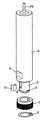
図1を参照すれば、締め付け装置は中空の円筒形シャフト部材1を含む。その前部、即ち図1に示す如き下部は、円筒形の締め付けスリーブ部材2を備える。締め付けスリーブ部材2はねじ山付きシャフト20を受け入れるための中心ボア3をもつ。中心ボア3の直径はその中に受け入れるべきねじ山付きシャフト20の外径に適合するのは言うまでもない。
【0013】
締め付けスリーブ部材2は中心ボア3内に開口する開口部4を備える。開口部4は径方向に可動の締め付け素子5を受け入れるよう適用される。この締め付け素子は詳細に後述するが、ほぼ方形の横断面を有している。これに関連して、径方向に可動であるということは、ボア3内に受け入れたねじ山付きシャフト20に近づいたり遠ざかったりできることを意味する。開口部4は締め付け素子5の寸法に適合する幅と高さをもつ横断面を有していて、締め付け素子が実質上ゼロの隙間をもって開口部4内を摺動するようになされている。かくして、締め付け素子5は捩れたり回転したりする可能性なしに開口部内に受け入れられ、また、その水平と垂直の位置が適切に限定される。引き続き、締め付け素子5の作動と正確なデザインにつき図3を参照して説明する。
【0014】
締め付けスリーブ素子2の外周の周りに、回転する環状の作動素子7が設けられており、この作動素子は締め付け素子5を径方向に移動させるよう適用される。締め付けスリーブ部材2の下端(図1、2に示す如きもの)は締め付けスリーブ部材2が滑り落ちるのを防止する即ち、作動素子7を所望の位置に保持する保持リング部材8を受け入れるための溝9を備える。
【0015】
中空の円筒形シャフト部材1の外面は基準面部分6を備え、締め付け装置が例えば工作機械に関して適切に限定された場所に位置決めされるのを可能になす。前記基準面部分6は適切にデザインされかつ位置決めされていて、この基準面部分により、締め付け装置の場所を、垂直方向において例えばその正面とその角度的方位の両方に関して、かつまたその長手方向中心軸線22の周りのその角度的方位に関して、決定できるようになす。その結果、締め付け装置全体およびその中に締め付けられたねじ山付きシャフト20は、正確に位置決めされることができる。
【0016】
図2は締め付け装置の本質的部品と素子を、特に、中空の円筒形シャフト部材1、開口部4を中に設けた締め付けスリーブ部材2、締め付け素子5、環状の作動部材7並びに保持リング部材8を分解斜視図で示す。更に、保持リング部材8を受け入れるための溝9は明瞭に認められる。最後に、ねじ山付きシャフト20は概略的に示されている。
【0017】
図3は締め付け素子5を斜視図で示す。図示の如く、締め付け素子5の正面(即ち図3の左側)部分は複数のねじ山回旋部11を備え、この回旋部はねじ山付きシャフト20のねじ山回旋部に適合する。締め付け素子5の背後または反対の面部分は丸み付けされている。更に、締め付け素子5の上記ねじ山回旋部11に隣接した横面部分16は面取りされている。最後に、締め付け素子5の横面のうちの1つは、方位付け用補助具として役立つ溝18を備えていて、締め付け素子5を常に同じ方位で開口部4内に挿入することを確実ならしめるようになす。
【0018】
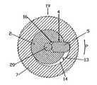
線A−A上の締め付け装置の拡大横断面図を示す図4に基づいて、締め付け装置のデザインと作動を引き続き説明する。この図に明瞭に認められるのは開口部4を備えた締め付けスリーブ部材2、締め付け素子5、回転する環状作動素子7、並びに該装置に締め付けられるべきねじ山付きシャフト20である。図4によれば、締め付け素子5はその休止位置で示されており、この休止位置ではそのねじ山回旋部はねじ山付きシャフト20のねじ山回旋部に掛合しない。従って、このねじ山付きシャフト20は固定されず、それ故軸線方向に可動となる。
【0019】
更に図4に見られる如く、環状の作動部材7の内部は正確には円形でないが、その内周の一部に沿って径方向に徐々に拡大する凹み部分14を備える。図4に示す如く、締め付け素子5の残りの位置では、締め付け部材5の丸み付けされた背面部分が上記の凹み部分15の最深部分に当接している。ねじ山付きシャフト20を締め付けるために、環状の作動部材7が矢印Pの方向に回される。それによって、締め付け部材5はねじ山付きシャフト20に対して径方向に動かされ、その結果、締め付け部材5のねじ山回旋部11はねじ山付きシャフト20のねじ山回旋部に掛合して、このねじ山付きシャフトを該締め付け装置に関して径方向にかつ軸線方向に動かないようにする。
【0020】
ねじ山付きシャフト20を解放するために、環状作動素子は矢印P方向と反対に回される。その結果、締め付け素子5の丸み付けされた背面部分はもはや環状作動部材7の凹み部分14の壁13に当接しないで、締め付け素子5はねじ山付きシャフト20から径方向に離れる向きに移動することができるようになる。環状作動素子7を解放した後、ねじ山付きシャフト20はそれを回すことによって軸線方向に移動することができる。もし図4に示す如く、環状作動部材7がその休止位置にあるならば、ねじ山付きシャフト20はそれを引っ張ることまたは押すことによって軸線方向に一様に移動することができる。というのは、締め付け素子5は自己ロッキング式のものでなく、ねじ山付きシャフト20を引っ張ることまたは押すことによって、そのねじ山回旋部は締め付け素子5を径方向外方へ押すからである。
【0021】
一旦ねじ山付きシャフト20を軸線方向に動かして新しい場所へ移動させ、そして環状作動素子7を締め付けたとき、締め付け素子5は再び径方向内方へ動かされ、その結果、そのねじ山回旋部11は、ねじ山付きシャフト20のねじ山回旋部に掛合して、このねじ山付きシャフト20を該締め付け装置に関して適切に限定された軸線方向および径方向位置に再び固定することになる。環状作動素子7の外面はその作動を容易にするために波形19を付されている。
【0022】
更に図4に認められる如く、中心ボア3内に開口する開口部4は中心ボア3とねじ山付きシャフト20に夫々面する端に円錐状に狭くされた部分をもつ。この円錐形部分は止めとして働き、この止めに対して、面取りされた正面部分16が当接して、締め付け素子5とねじ山付きシャフト20のねじ山回旋部の間に深過ぎるまたは緊密過ぎる掛合をしないようになす。
【0023】
上述されかつ図示された如き本発明の締め付け装置の実施例は、特に小直径のねじ山付きシャフト20を締め付けるのに適し、またそれらのシャフトが例えばM3乃至M10の間のメートル寸法のねじ山を侵食成形(eroding)するために使用されるときには、電極の形をなすねじ山付きシャフトとして適する。これに関して、M3のねじ山を侵食成形するためのねじ山付きシャフトは0.5ミリメートルのピッチを有して、1.7ミリメートルの外径しかもたないことは理解されるべきである。更に、かかる小さいねじ山を慣例のねじ山切削によって作るのは極めて困難であることは言うまでもない。従って、図示した締め付け素子5をもつ実施例は小さい外径をもつねじ山付きシャフト用に特に適する。というのは、相応のねじ山回旋部11をもつ締め付け素子5の正面部分を形成するのは比較的容易であるからである。
【0024】
環状作動素子7が解放されている図4に示す休止位置に締め付け素子5を保持するために、締め付け素子5をその休止位置に偏倚させるばね部材(図示せず)を備えることができる。
【図面の簡単な説明】
【図1】 本発明装置の縦断面図である。
【図2】 該装置の本質的部品と素子を示す分解斜視図である。
【図3】 締め付け素子の斜視図である。
【図4】 図1の線A-A上の該装置の横断面図である。
【符号の説明】
1 円筒形シャフト部材
2 締め付けスリーブ部材
3 中心ボア
4 開口部
5 締め付け素子
6 基準面部分
7 環状作動素子
8 保持リング
11 ねじ山回旋部
14 凹み部分
20 ねじ山付きシャフト[0001]
BACKGROUND OF THE INVENTION
The present invention relates to a threaded shaft, and in particular to a clamping device for fixing a threaded shaft used as an electrode for eroding the thread, so as not to rotate.
[0002]
[Prior art]
A clamping device in the form of a split chuck or collet chuck, which is inserted into a corresponding chuck holding device and clamped therein, in order to fix and tighten each threaded shaft used as an electrode for erosion forming the thread Is usually used. A threaded shaft to be securely held in place is inserted into the central opening of the split chuck and clamped and fixed in the desired position. This type of fixation has two basic drawbacks. First, only the crest of the thread turn is in contact with the inner wall of the split chuck and tightened therein, so that the thread turn is damaged, especially in the case of V-shaped threads. Second, the position of the thread relative to the split chuck and chuck holder is not precisely limited, respectively. As a result, the position of the thread and the thread turn relative to the chuck holder, respectively, changes when the position of the threaded shaft is adjusted, for example, when an axial readjustment required due to wear is made. . However, the process of erosion of the thread first involves roughing several threads in the first part of the threaded electrode shaft and then adjusting the position of the threaded electrode shaft before finalizing In addition, since it is a common practice to erosion-mold the pre-roughened thread on the second unused portion of the threaded electrode shaft, the aforementioned first portion of the threaded electrode shaft, There is a risk that the position of the above-mentioned second part of the threaded electrode shaft does not match. As a result, precise thread sides cannot be made, and the final thread will not meet high quality standards. Thus, it goes without saying that the used part of the threaded electrode shaft is cut off before applying a new unused part of the threaded electrode shaft.
[0003]
U.S. Pat. No. 2,629,277 discloses a stud bolt wrench for inserting and removing stud bolts. The wrench includes a body with an axial base bore and a base portion having a substantially coaxial bore extending about 180 ° around the circumference. In addition, the base portion has a transverse slot that intersects both the base bore and the edge. A two-part tightening set is provided to secure the stud bolt. The fastening set consists of a stationary part and a movable part, both parts being provided with a thread turning part for engaging with a stud bolt. The immovable part is inserted into the edge but the movable clamping part is received in the slot. The two clamping parts are biased by springs so that stud bolts received in the clamping set are clamped and secured therein.
[0004]
German Patent No. 288,152 discloses a tool for inserting and removing stud bolts. The tool consists of an outer housing, which has several eccentric curved surfaces on its inner surface. Accepted in these curved surfaces is a jaw with a catch that projects inwardly. The capturing part includes a thread turning part for fixing the stud bolt. The jaws are held in their position by springs. The outer housing is turned relative to the jaws to secure the stud bolt in the tool. Thereby, the jaws are moved radially inward under the influence of the eccentric curved surface so that the thread turning of the jaws engages the corresponding thread of the stud bolt.
[0005]
Finally, U.S. Pat. No. 2,073,274 discloses a stud screw wrench having a hexagonal housing having a central opening defined by four cam-shaped surfaces. Inserted into the opening is a sleeve with four slots, which has an internal thread for securing the stud bolt. The sleeve is divided into four sections by the slot. The four sleeve sections are pressed inward when the housing rotates with respect to the sleeve under the influence of the cam-shaped surface. Thus, the stud bolt received in the tool is fastened and fixed.
[0006]
A fundamental drawback of the above-described device is seen in the fact that the position of the threaded bolt or shaft is not precisely defined or cannot be predicted accurately. The reason for this is that the position of the bolt or shaft relative to the clamping device can be tightened with any amount of torque to bring the clamping jaws to their clamping position in the case of devices with rotating clamping jaws or elements. Because it depends on the fact that it was and what final position they were in.
[0007]
On the other hand, since the devices described above do not have the equipment or means for aligning them, the bolt or shaft cannot be accurately defined in both the axial and angular position of the bolt and shaft. , Will be accepted in it.
[0008]
[Problems to be solved by the invention]
The object of the present invention is to fix the threaded shaft in a fixed and non-rotating manner without the above-mentioned drawbacks, i.e. the threaded shaft with high accuracy which can be quickly, easily and reproducibly. An object of the present invention is to provide a fastening device that can be fixed.
[0009]
[Means for Solving the Problems]
To achieve these and other objectives, the present invention provides an apparatus for securing and tightening a threaded shaft that includes a hollow tubular housing having a central longitudinal axis. The hollow tubular housing includes an opening extending radially with respect to the central longitudinal axis and having a square cross-sectional shape. A clamping element is slidably received in the opening and has a front surface with a thread turn. The actuating element slides the clamping element received in the opening towards the central bore and locks the threaded shaft inserted into the central bore with high positional accuracy and reproducibility. Provided for.
[0010]
Since the opening and the clamping element have a rectangular shape, it is guaranteed that the position of the clamping element relative to the clamping device does not change, so that the threaded shaft is always clamped in the same exact axial position in the device. Will be.
[0011]
Preferably, the housing of the device is provided with a reference surface part, so that the clamping device as a whole, and of course the threaded shaft clamped therein, can be precisely aligned, for example with respect to the machine tool. .
Hereinafter, an embodiment of the present invention device will be described with reference to the accompanying drawings.
[0012]
DETAILED DESCRIPTION OF THE INVENTION
Referring to FIG. 1, the clamping device includes a hollow cylindrical shaft member 1. The front part, ie the lower part as shown in FIG. 1, comprises a cylindrical clamping sleeve member 2. The clamping sleeve member 2 has a central bore 3 for receiving a threaded
[0013]
The fastening sleeve member 2 comprises an
[0014]
A rotating annular actuating element 7 is provided around the outer periphery of the clamping sleeve element 2 and is adapted to move the
[0015]
The outer surface of the hollow cylindrical shaft member 1 is provided with a
[0016]
FIG. 2 shows the essential components and elements of the clamping device, in particular a hollow cylindrical shaft member 1, a clamping sleeve member 2 with an
[0017]
FIG. 3 shows the
[0018]
The design and operation of the clamping device will continue to be described with reference to FIG. 4 showing an enlarged cross-sectional view of the clamping device on line AA. Clearly seen in this figure are a clamping sleeve member 2 with an
[0019]
Further, as can be seen in FIG. 4, the inside of the annular actuating member 7 is not exactly circular, but includes a recessed
[0020]
To release the threaded
[0021]
Once the threaded
[0022]
Further, as can be seen in FIG. 4, the
[0023]
The embodiment of the clamping device of the present invention as described and illustrated above is particularly suitable for tightening small diameter threaded
[0024]
In order to hold the
[Brief description of the drawings]
FIG. 1 is a longitudinal sectional view of a device of the present invention.
FIG. 2 is an exploded perspective view showing essential components and elements of the apparatus.
FIG. 3 is a perspective view of a clamping element.
4 is a cross-sectional view of the device along line AA in FIG. 1. FIG.
[Explanation of symbols]
DESCRIPTION OF SYMBOLS 1 Cylindrical shaft member 2 Tightening sleeve member 3 Center bore 4
Claims (10)
Translated fromJapanese中心の長手方向軸線を画定する中心ボア手段を持つ中空管状のハウジング手段であって、前記中心の長手方向軸線に関して径方向に延びかつ方形の断面形状をもつ開口部手段を有し、前記中心ボア手段は、径方向に延びる前記開口部手段の開口部を除いて、前記ねじ山付きシャフトの外径に適合する直径を有し、長手方向軸線に沿って延びるボア内面を有する該ハウジング手段と、
前記開口部手段内に摺動可能に受け入れられかつねじ山回旋部手段を備えた正面手段を有する1個の締め付け素子よりなる締め付け手段であって、前記開口部手段との間の隙間がゼロとなるよう前記開口部手段の方形断面形状と同一の方形断面形状を有する該締め付け手段と、
前記開口部手段内に受け入れられた前記締め付け手段を前記中心ボア手段に向かって摺動状に移動させかつ前記中心ボア手段内に挿入されたねじ山付きシャフトをロックするための作動手段であって、環状の回転する回転カラー手段を含み、この回転カラー手段は、前記ハウジング手段の周りに配置されたかつ前記締め付け素子に面する径方向に徐々に拡大する凹み部分を有する内側円形断面をもち、この凹み部分を有する内側円形断面は、前記回転カラー手段の軸線方向に一定の形状であり、前記カラー手段が前記長手方向軸線の周りに回転したとき、前記締め付け手段を前記中心ボア手段の前記ボア内面に向かって移動させるようになされている該作動手段と
を含むことを特徴とする締め付け装置。In a tightening device for fixing a threaded shaft so as not to rotate,
A central bore means housing meanslifting one hollow tubularwith defining a longitudinal axis of the center has an opening means having a longitudinal extending radially with respect to axis and square cross-sectional shape of the center, the center The housing means having a bore inner surface extending along a longitudinal axis, the bore means having a diameter adapted to the outer diameter of the threaded shaft, except for an opening of the opening means extending in a radial direction; ,
A clamping means comprising one clamping element having a front means slidably received in the opening means and provided with a thread turning means, the gap between the opening means being zero and The clamping means having a square cross-sectional shape identical to the square cross-sectional shape of the opening means,
Actuating means for slidably moving the clamping means received in the opening means toward the central bore means and locking a threaded shaft inserted into the central bore means; includes rotating color means for rotating the annular, the rotating collar means has a inner circularcross-section having a gradually recessed portion to expand radially facing the arranged and the clamping element around said housing means The inner circular cross-section with the recessed portion is of a constant shape in the axial direction of the rotating collar means, and when the collar means is rotated about the longitudinal axis, the clamping means is connected to the central bore means. And an actuating means adapted to move toward the bore inner surface.
Applications Claiming Priority (2)
| Application Number | Priority Date | Filing Date | Title |
|---|---|---|---|
| CH20010778/01 | 2001-04-27 | ||
| CH7782001 | 2001-04-27 |
Publications (2)
| Publication Number | Publication Date |
|---|---|
| JP2002346841A JP2002346841A (en) | 2002-12-04 |
| JP4326185B2true JP4326185B2 (en) | 2009-09-02 |
Family
ID=4535985
Family Applications (1)
| Application Number | Title | Priority Date | Filing Date |
|---|---|---|---|
| JP2002106927AExpired - Fee RelatedJP4326185B2 (en) | 2001-04-27 | 2002-04-09 | Tightening device |
Country Status (11)
| Country | Link |
|---|---|
| US (1) | US6702504B2 (en) |
| EP (1) | EP1262266B1 (en) |
| JP (1) | JP4326185B2 (en) |
| KR (1) | KR100794900B1 (en) |
| CN (1) | CN1302886C (en) |
| AT (1) | ATE366633T1 (en) |
| CA (1) | CA2382906C (en) |
| DE (2) | DE50210439D1 (en) |
| DK (1) | DK1262266T3 (en) |
| ES (1) | ES2289071T3 (en) |
| PT (1) | PT1262266E (en) |
Families Citing this family (12)
| Publication number | Priority date | Publication date | Assignee | Title |
|---|---|---|---|---|
| WO2013121533A1 (en) | 2012-02-15 | 2013-08-22 | 三菱電機株式会社 | Electrical discharge machining device |
| CN103008801B (en)* | 2012-11-29 | 2015-02-11 | 中山市利群精密实业有限公司 | Discharge machining process adopting indirect neutral method |
| US9039090B2 (en) | 2013-03-14 | 2015-05-26 | Leggett & Platt Canada Co. | Height adjustment mechanism suitable for a footring |
| CN204308815U (en)* | 2014-08-06 | 2015-05-06 | 上海齐迈五金有限公司 | A kind of spanner gathering sleeve |
| DE102016100374A1 (en) | 2016-01-11 | 2017-07-13 | Retero Gmbh | Fixing device, wire erosion machine or laser system and method for wire erosion or laser |
| US9776267B1 (en)* | 2016-06-14 | 2017-10-03 | Johnson Technology, Inc. | Electrical discharge machining electrode holder |
| CN208907429U (en)* | 2018-07-31 | 2019-05-28 | 中山市美图塑料工业有限公司 | A nut that can be quickly assembled and disassembled and a threaded fastening assembly including the same |
| CN109773700A (en)* | 2018-12-24 | 2019-05-21 | 河海大学常州校区 | A screwdriver that prevents screws from falling out |
| CN111185640B (en)* | 2020-01-14 | 2021-01-26 | 宝利根(成都)精密工业有限公司 | Discharge forming processing method for chamfer of any angle of die part |
| US11413728B2 (en)* | 2020-02-25 | 2022-08-16 | Nissan North America, Inc. | Tightening tool |
| US12102369B2 (en)* | 2021-05-13 | 2024-10-01 | DePuy Synthes Products, Inc. | Surgical impacting tool interfaces |
| WO2024188805A1 (en)* | 2023-03-15 | 2024-09-19 | Arno Giehl | Nut |
Family Cites Families (24)
| Publication number | Priority date | Publication date | Assignee | Title |
|---|---|---|---|---|
| DE288152C (en)* | ||||
| US2043274A (en)* | 1934-10-16 | 1936-06-09 | Fred C Wegner | Stud screw wrench |
| US2629277A (en)* | 1949-10-04 | 1953-02-24 | Ralph A Valvano | Stud bolt wrench |
| US3194938A (en)* | 1962-10-09 | 1965-07-13 | L C Miller Company | Method for producing parts by electrical erosion |
| US3741573A (en)* | 1971-07-12 | 1973-06-26 | S Treer | Tool holder for a machine tool or the like |
| US3827728A (en)* | 1972-10-30 | 1974-08-06 | Vetco Offshore Ind Inc | Pipe connectors |
| JPS5234484A (en)* | 1975-04-12 | 1977-03-16 | Takefusa Takeda | Variable processing tool securing and holding device |
| US4074912A (en)* | 1976-09-20 | 1978-02-21 | Vetco Offshore Industries, Inc. | Releasable rigid pile connector apparatus |
| CN85105233A (en)* | 1985-04-17 | 1986-10-22 | 莫诺格拉姆工业有限公司 | A kind of being used for of having improved inserts and the pressure release, wire-pin clamp of the instrument of extraction out automatically |
| DE3520324A1 (en)* | 1985-06-07 | 1986-12-11 | Hilti Ag, Schaan | DRILL CHUCK FOR HAND TOOLS |
| JPS61201745U (en)* | 1985-06-10 | 1986-12-18 | ||
| JPS62166906A (en)* | 1986-01-21 | 1987-07-23 | Matsushita Electric Works Ltd | Chucking tool |
| DE3717614A1 (en)* | 1987-05-25 | 1988-12-15 | Hilti Ag | TOOL HOLDER FOR TOOLS |
| JPH03208523A (en)* | 1990-01-09 | 1991-09-11 | Seiko Epson Corp | Electrode material holding device |
| CN2154760Y (en)* | 1992-06-30 | 1994-02-02 | 上海工程技术大学 | Combined electrode clamp |
| US5315902A (en)* | 1992-11-24 | 1994-05-31 | Gripping Tools Technologies, Inc. | Stud removing tool |
| US5640430A (en)* | 1993-09-02 | 1997-06-17 | Motorola, Inc. | Method for detecting valid data in a data stream |
| FR2742193B1 (en)* | 1995-12-08 | 1998-02-27 | Mavic Sa | QUICK LOCKING AXLE FOR USE ON A CYCLE |
| US5766446A (en)* | 1996-03-05 | 1998-06-16 | Candescent Technologies Corporation | Electrochemical removal of material, particularly excess emitter material in electron-emitting device |
| JPH10225823A (en)* | 1997-02-10 | 1998-08-25 | Watanabe Tekko Kk | Chuck device |
| US6451698B1 (en)* | 1999-04-07 | 2002-09-17 | Koninklijke Philips Electronics N.V. | System and method for preventing electrochemical erosion by depositing a protective film |
| US6527920B1 (en)* | 2000-05-10 | 2003-03-04 | Novellus Systems, Inc. | Copper electroplating apparatus |
| US6811658B2 (en)* | 2000-06-29 | 2004-11-02 | Ebara Corporation | Apparatus for forming interconnects |
| US6932896B2 (en)* | 2001-03-30 | 2005-08-23 | Nutool, Inc. | Method and apparatus for avoiding particle accumulation in electrodeposition |
- 2002
- 2002-04-03EPEP02405258Apatent/EP1262266B1/ennot_activeExpired - Lifetime
- 2002-04-03PTPT02405258Tpatent/PT1262266E/enunknown
- 2002-04-03ESES02405258Tpatent/ES2289071T3/ennot_activeExpired - Lifetime
- 2002-04-03DEDE50210439Tpatent/DE50210439D1/ennot_activeExpired - Lifetime
- 2002-04-03ATAT02405258Tpatent/ATE366633T1/enactive
- 2002-04-03DKDK02405258Tpatent/DK1262266T3/enactive
- 2002-04-05USUS10/117,391patent/US6702504B2/ennot_activeExpired - Fee Related
- 2002-04-09JPJP2002106927Apatent/JP4326185B2/ennot_activeExpired - Fee Related
- 2002-04-22CACA002382906Apatent/CA2382906C/ennot_activeExpired - Fee Related
- 2002-04-24DEDE20206516Upatent/DE20206516U1/ennot_activeExpired - Lifetime
- 2002-04-26KRKR1020020022861Apatent/KR100794900B1/ennot_activeExpired - Fee Related
- 2002-04-27CNCNB021189552Apatent/CN1302886C/ennot_activeExpired - Fee Related
Also Published As
| Publication number | Publication date |
|---|---|
| US6702504B2 (en) | 2004-03-09 |
| US20020159830A1 (en) | 2002-10-31 |
| KR20020083463A (en) | 2002-11-02 |
| EP1262266A1 (en) | 2002-12-04 |
| CN1302886C (en) | 2007-03-07 |
| CN1383951A (en) | 2002-12-11 |
| ES2289071T3 (en) | 2008-02-01 |
| JP2002346841A (en) | 2002-12-04 |
| CA2382906A1 (en) | 2002-10-27 |
| EP1262266B1 (en) | 2007-07-11 |
| KR100794900B1 (en) | 2008-01-14 |
| DK1262266T3 (en) | 2007-11-12 |
| PT1262266E (en) | 2007-07-26 |
| DE20206516U1 (en) | 2002-08-29 |
| CA2382906C (en) | 2007-10-30 |
| ATE366633T1 (en) | 2007-08-15 |
| DE50210439D1 (en) | 2007-08-23 |
Similar Documents
| Publication | Publication Date | Title |
|---|---|---|
| JP4326185B2 (en) | Tightening device | |
| JP2668284B2 (en) | Tool holder with tool change mechanism | |
| US6286823B1 (en) | Workpiece indexing and clamping system | |
| US20140353929A1 (en) | Expanding arbor | |
| US2634641A (en) | Fastener-holding socket wrench | |
| WO2013037990A1 (en) | Expanding arbor | |
| GB1566855A (en) | Drill chuck | |
| US20050281631A1 (en) | Pin locking system | |
| US6974287B2 (en) | Tool clamping device | |
| JP2006078492A (en) | Fastening apparatus for fitting wheel to axle of balancing machine | |
| US5341710A (en) | Coupling structure and method | |
| KR20120131247A (en) | Quick change arbor, hole cutter, and method | |
| US8272646B2 (en) | Quick change jaw system for chucks | |
| JP2656936B2 (en) | Tool adapter attachment / detachment fixing device | |
| US4746131A (en) | Apparatus for internal chucking of soft three-jaw chucks on lathes | |
| CA2155589C (en) | Independent chuck jaw insert having a registration surface enabling locking at a specific position | |
| US20210107069A1 (en) | Adaptive Work-Stop | |
| JP6185158B2 (en) | Collet assembly | |
| US20220281016A1 (en) | Chuck for gripping and moving cylindrical bodies, in particular fittings and pipe segments, and apparatus including the chuck | |
| JP2010247247A (en) | Chuck device of lathe and centering method therefor | |
| CN115847155A (en) | Clamping device for a tool or workpiece with a tensioning collet and a coupling element | |
| CA2155591C (en) | Chuck jaw locking apparatus for a rotatable machine tool | |
| US3344690A (en) | Boring bar assembly | |
| US5772219A (en) | Collet stop | |
| JP2781068B2 (en) | Roller upsetting tool |
Legal Events
| Date | Code | Title | Description |
|---|---|---|---|
| A621 | Written request for application examination | Free format text:JAPANESE INTERMEDIATE CODE: A621 Effective date:20050408 | |
| A131 | Notification of reasons for refusal | Free format text:JAPANESE INTERMEDIATE CODE: A131 Effective date:20080129 | |
| A601 | Written request for extension of time | Free format text:JAPANESE INTERMEDIATE CODE: A601 Effective date:20080430 | |
| A602 | Written permission of extension of time | Free format text:JAPANESE INTERMEDIATE CODE: A602 Effective date:20080507 | |
| A521 | Request for written amendment filed | Free format text:JAPANESE INTERMEDIATE CODE: A523 Effective date:20080729 | |
| A131 | Notification of reasons for refusal | Free format text:JAPANESE INTERMEDIATE CODE: A131 Effective date:20080902 | |
| A521 | Request for written amendment filed | Free format text:JAPANESE INTERMEDIATE CODE: A523 Effective date:20081201 | |
| A131 | Notification of reasons for refusal | Free format text:JAPANESE INTERMEDIATE CODE: A131 Effective date:20090203 | |
| A521 | Request for written amendment filed | Free format text:JAPANESE INTERMEDIATE CODE: A523 Effective date:20090507 | |
| TRDD | Decision of grant or rejection written | ||
| A01 | Written decision to grant a patent or to grant a registration (utility model) | Free format text:JAPANESE INTERMEDIATE CODE: A01 Effective date:20090602 | |
| A01 | Written decision to grant a patent or to grant a registration (utility model) | Free format text:JAPANESE INTERMEDIATE CODE: A01 | |
| A61 | First payment of annual fees (during grant procedure) | Free format text:JAPANESE INTERMEDIATE CODE: A61 Effective date:20090609 | |
| FPAY | Renewal fee payment (event date is renewal date of database) | Free format text:PAYMENT UNTIL: 20120619 Year of fee payment:3 | |
| R150 | Certificate of patent or registration of utility model | Free format text:JAPANESE INTERMEDIATE CODE: R150 | |
| FPAY | Renewal fee payment (event date is renewal date of database) | Free format text:PAYMENT UNTIL: 20120619 Year of fee payment:3 | |
| FPAY | Renewal fee payment (event date is renewal date of database) | Free format text:PAYMENT UNTIL: 20130619 Year of fee payment:4 | |
| R250 | Receipt of annual fees | Free format text:JAPANESE INTERMEDIATE CODE: R250 | |
| R250 | Receipt of annual fees | Free format text:JAPANESE INTERMEDIATE CODE: R250 | |
| R250 | Receipt of annual fees | Free format text:JAPANESE INTERMEDIATE CODE: R250 | |
| LAPS | Cancellation because of no payment of annual fees |