JP4325969B2 - Skin impedance fluctuation evaluation device - Google Patents
Skin impedance fluctuation evaluation deviceDownload PDFInfo
- Publication number
- JP4325969B2 JP4325969B2JP2000557751AJP2000557751AJP4325969B2JP 4325969 B2JP4325969 B2JP 4325969B2JP 2000557751 AJP2000557751 AJP 2000557751AJP 2000557751 AJP2000557751 AJP 2000557751AJP 4325969 B2JP4325969 B2JP 4325969B2
- Authority
- JP
- Japan
- Prior art keywords
- electrode
- electrodes
- measurement
- skin
- resistance
- Prior art date
- Legal status (The legal status is an assumption and is not a legal conclusion. Google has not performed a legal analysis and makes no representation as to the accuracy of the status listed.)
- Expired - Fee Related
Links
Images


Classifications
- A—HUMAN NECESSITIES
- A61—MEDICAL OR VETERINARY SCIENCE; HYGIENE
- A61B—DIAGNOSIS; SURGERY; IDENTIFICATION
- A61B5/00—Measuring for diagnostic purposes; Identification of persons
- A61B5/05—Detecting, measuring or recording for diagnosis by means of electric currents or magnetic fields; Measuring using microwaves or radio waves
- A61B5/053—Measuring electrical impedance or conductance of a portion of the body
- A61B5/0531—Measuring skin impedance
- A61B5/0532—Measuring skin impedance specially adapted for acupuncture or moxibustion
- A—HUMAN NECESSITIES
- A61—MEDICAL OR VETERINARY SCIENCE; HYGIENE
- A61B—DIAGNOSIS; SURGERY; IDENTIFICATION
- A61B5/00—Measuring for diagnostic purposes; Identification of persons
- A61B5/05—Detecting, measuring or recording for diagnosis by means of electric currents or magnetic fields; Measuring using microwaves or radio waves
- A61B5/053—Measuring electrical impedance or conductance of a portion of the body
- A61B5/0531—Measuring skin impedance
- A61B5/0533—Measuring galvanic skin response
- A—HUMAN NECESSITIES
- A61—MEDICAL OR VETERINARY SCIENCE; HYGIENE
- A61B—DIAGNOSIS; SURGERY; IDENTIFICATION
- A61B5/00—Measuring for diagnostic purposes; Identification of persons
- A61B5/41—Detecting, measuring or recording for evaluating the immune or lymphatic systems
- A61B5/414—Evaluating particular organs or parts of the immune or lymphatic systems
- A61B5/416—Evaluating particular organs or parts of the immune or lymphatic systems the spleen
Landscapes
- Health & Medical Sciences (AREA)
- Life Sciences & Earth Sciences (AREA)
- Surgery (AREA)
- Biomedical Technology (AREA)
- General Health & Medical Sciences (AREA)
- Biophysics (AREA)
- Pathology (AREA)
- Engineering & Computer Science (AREA)
- Animal Behavior & Ethology (AREA)
- Heart & Thoracic Surgery (AREA)
- Medical Informatics (AREA)
- Molecular Biology (AREA)
- Physics & Mathematics (AREA)
- Veterinary Medicine (AREA)
- Dermatology (AREA)
- Public Health (AREA)
- Nuclear Medicine, Radiotherapy & Molecular Imaging (AREA)
- Radiology & Medical Imaging (AREA)
- Pain & Pain Management (AREA)
- Immunology (AREA)
- Vascular Medicine (AREA)
- Measurement And Recording Of Electrical Phenomena And Electrical Characteristics Of The Living Body (AREA)
- Investigating Or Analyzing Materials By The Use Of Electric Means (AREA)
- Electrotherapy Devices (AREA)
- Measurement Of Resistance Or Impedance (AREA)
- Surgical Instruments (AREA)
Abstract
Description
Translated fromJapanese(技術分野)
本発明は、人間または動物の体内器官の健康状態を推定するために、皮膚インピーダンスを自動評価する装置及び方法に関するものである。
【0001】
(背景技術)
皮膚インピーダンス値を利用して、器官の診断を行う既存の方法は、非比率計測による、ごく基本的な皮膚インピーダンスの測定結果に基づくものであり、患者の情動状態、筋張力、測定時間、接触面積、及び、測定電極の圧力を含む多数の変数、及び、個人間におけるさまざまな生理的相違によって左右される、一貫性のない、信頼性に欠ける結果が生じることになる。
【0002】
多年にわたる研究の結果、現在では、発明者は、人間または動物の体内器官には、皮膚の電気的特性を測定することによって、対応する体内器官に関する情報を引き出すことが可能な前記皮膚の対応する領域が備わっていることを確信している。さらに、発明者の信ずるところによれば、前記皮膚の対応領域には、例えば、対応する器官によって生じる痛みの癒し及び/または軽減能力といった、反射性理学療法(針治療を含む)の科学に関連した他の特性も備わっている。
【0003】
さらに発明者の信ずるところによれば、これらの対応する皮膚領域は、地図作成が可能であり、その地図は、それぞれの異なる個人に適用可能である。
【0004】
発明者の発見によれば、耳介はとりわけ正確な地図作成が可能であり、ほとんどの文化において、耳の皮膚は露出されており、衣服を脱ぐことを必要とせずに検査することができるので、本発明の方法に最も適している。
【0005】
本明細書において、「インピーダンス」という用語は、その文脈によって明確に相容れないことが示されない限り、抵抗を含むものと理解すべきである。
【0006】
(発明の開示)
インピーダンス変動は、2つの方法で測定可能である。
【0007】
方法1:AC評価
較正電極及び基準電極を用いて特定の周波数及び特定の皮膚領域で測定されるACインピーダンスと、測定電極及び基準電極を用いて同様の周波数及び同じ領域で測定されるインピーダンスとの差を利用して、検査を受ける皮膚領域に対応する体内器官の健康状態が判定される。較正電極及び基準電極の接触面積は、測定電極の皮膚接触面積より相対的に広い。
【0008】
方法2:DC評価
「ブレーク・スルー効果」という用語は、電極間に十分な電位差が加えられた後に見られる、皮膚電気抵抗の突然の大幅な低下を表している。
【0009】
電極間の皮膚は、ブレーク・スルー効果を生じるように選択された大きさのDC電位にさらされる。皮膚のDC抵抗は、基準電極に対して負の極性が付与された測定電極との間で測定され、同じ皮膚領域のDC抵抗が、再度、ただし、基準電極に対して正の極性が付与された測定電極によって測定される。これらの2つの値の比率を用いて、検査を受ける皮膚領域に対応する体内器官の健康状態が判定される。
【0010】
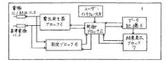
一般に、本発明による装置には、下記の機能ブロックを含むことが可能である:
測定及び/または較正電極、基準電極、電圧発生ブロック、測定ブロック、制御ブロック、ユーザ・インターフェイス・ブロック、結果提示ブロック、及び、オプションによりデータ記憶ブロック。
【0011】
電圧発生ブロックは、測定電極と基準電極の間、または、較正電極と基準電極の間に電位差を発生する。電圧発生ブロックは、制御ブロックに接続されて、その制御を受ける。測定ブロックは、測定電極及び基準電極に接続されている(図1)。
【0012】
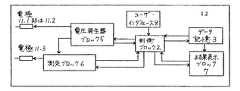
測定ブロックは、測定電極と基準電極または較正電極の間のインピーダンスを測定する。代替案として、電圧発生ブロックは、測定ブロックを介して、測定電極または基準電極に接続することも可能である(図2)。測定ブロックの最終目的は、測定電極と基準電極の間のインピーダンスまたは抵抗を判定するために利用可能なパラメータ(電圧または電流のような)を測定することにある。測定ブロックは、制御ブロックに接続されている。
【0013】
制御ブロックは、ユーザ・インターフェイス・ブロック(もしあれば)、データ記憶ブロック(もしあれば)、結果提示ブロック、電圧発生ブロック、及び、測定ブロックに接続されている。制御ブロックは、電圧発生ブロックによって発生する電圧を設定する。制御ブロックは、測定ブロックから受信した情報を利用して、ブレーク・スルー効果、及び、抵抗の非対称性を検出する。制御ブロックは、データ記憶ブロック(もしあれば)に情報を記憶し、読み出すことが可能である。制御ブロックは、結果提示ブロックを介して測定結果をユーザに知らせる。結果提示ブロックは、結果、すなわち、制御ブロックによって得られた体内器官の健康状態をユーザに知らせるため、視覚または音声表示を発生することが可能である。
【0014】
動作の説明
多くの実験研究の後、発明者は、信頼性の高い結果を得るために、本発明による広義の装置を以下に示すように動作させることができることを見いだした。
【0015】
方法1:AC評価
較正電極は、健康状態を決定する被験者の臓器に対応する関連する皮膚領域に接触させて配置される。基準電極は、どこか他の皮膚領域(通常は被験者の手)に接触させて配置される。制御ブロックは、電圧発生器ブロックを使用して、較正電極と基準電極との間に特定の周波数と振幅のAC信号を生成する。制御ブロックは、測定ブロックによって電極間のインピーダンスを決定する。制御ブロックは、そのインピーダンス値をデータ記憶ブロックに記憶する(「較正インピーダンス」という)。制御ブロックは、結果表示ブロックにより、較正インピーダンスが決定されたことを示す信号を出す。較正電極が取り外され、測定電極が、検査を行う皮膚領域に配置される。制御ブロックは、電圧発生器ブロックを使用して、較正電極と基準電極との間に同じ周波数と振幅のAC信号を生成する。
【0016】
制御ブロックは、較正インピーダンスと測定電極で測定したインピーダンスとの比率を決定し、その比率を臓器の健康状態の指示に変換する。制御ブロックは、その結果を結果表示ブロック(たとえば、疾患強度百分率目盛)上に表示する。
【0017】
この結果は、次の式により計算された百分率の形で表示されると好都合である。
【0018】
%疾患=(1−I測定/I基準)x100、または
%疾患=(1−R基準/R測定)x100
臓器の健康状態によって異なる百分率の範囲が対応する。一般に、0〜40%は、当該の臓器の健康状態を示し、40〜60%は、健康状態の上限を示し、60〜80%は、亜急性状態を示し、80〜100%は、急性状態を示す。
【0019】
方法2:DC評価
基準電極は、任意の皮膚領域に接触して配置される。測定電極は、健康状態を決定する臓器に対応する特定の皮膚部分に接触して配置される。制御ブロックは、電圧発生器ブロックを使用して電極間にDC電位差を生成する。制御ブロックは、測定ブロックにより、電極間の抵抗を決定する。制御ブロックは、DC電位差を調整して、抵抗がある一定のしきい値よりも低くなるかまたは突然急激に低下し始める(ブレークスルー効果)まで抵抗を調べる。制御ブロックは、抵抗を安定した値が得られるまで調べる。制御ブロックは、その抵抗値をデータ記憶ブロックに記憶する(「基準抵抗」という)。
【0020】
制御ブロックは、測定電極と基準電極の極性を互いに反転させ、電圧発生器ブロックを使用して電極の両側にDC電位を印加する。制御ブロックは、測定ブロックにより、電極間の抵抗を決定する(「測定抵抗」という)。
【0021】
制御ブロックは、「測定抵抗」と「基準抵抗」との比率を決定し、この比率から疾患の強度を計算する。計算には次の式が使用される。
【0022】
%疾患=(1−I測定/I基準)x100、または
%疾患=(1−I基準/R測定)x100
制御ブロックは、この結果を結果表示ブロック上に表示する(たとえば、疾患の強度さ百分率目盛で)。
【0023】
結果は、臓器の健康状態によって異なる百分率の範囲の百分率の形で表示されると好都合である。一般に、0〜40%は、当該の臓器の健康状態を示し、40〜60%は、健康状態の上限を示し、60〜80%は亜急性状態を示し、80〜100%は、急性状態を示す。
【0024】
ブレークスルー効果の誘導が最良の場合、基準電極に対して負の極性を有する測定電極によって基準抵抗の測定が行われるが、電極間の電位差が大きい場合には、極性を反転した場合にブレークスルー効果が観察されることがあると考えられる。
【0025】
DC法を使用するとき、臓器が健康でない場合は、基準電極に対して負の極性を有する測定電極よりも基準電極に対して正の極性を有する測定電極のほうが高い抵抗が測定される(たとえば、30kΩに対して300kΩ)。同様に、AC法を使用するとき、測定電極を使用して得られた測定値は、較正電極を使用して得られた測定値よりも高いインピーダンスを示す。
【0026】
また、DC法を使用するときにAC信号を使用することもできる。
【0027】
耳介のような身体の薄い皮膚領域には、AC法とDC法の両方の評価法が有効であるが、DC評価法が好ましい。足などの身体の厚い皮膚部分には、厚い皮膚領域がブレークスルー効果を生じるのに高い電圧を必要とするので、これが被験者に痛みを与えるのを避けるためAC法が好ましい。
【0028】
本発明者は、以上説明したような装置が、新しい測定法と比例測定法を使用し、個体間の様々な生理学的差異、患者の情緒的状態、筋肉の緊張および測定時間の影響を受けない一貫しかつ再現可能な診断結果を達成すると考える。結果は、疾患の強度に依存し、圧力の影響はきわめて小さい。
【0029】
実施例
例1:
胃潰瘍と診断された第1の検査において、次の結果が得られた。
【0030】
耳介投射領域(薄い皮膚−DC測定):基準抵抗=10kΩ、
胃投射領域:測定抵抗=200kΩ
すなわち、疾患状態の95%
健康な臓器投射領域:測定抵抗=10〜25kΩ
すなわち、疾患状態の0〜60%
足投射領域(厚い皮膚−AC測定):基準抵抗=15kΩ(250Hzで)
胃投射領域:測定抵抗=300kΩ
すなわち、疾患状態の95%
健康な臓器投射領域:測定抵抗=15〜37.5kΩ
すなわち、疾患状態の0〜60%
例2:
腎盂腎炎(腎感染)
耳介投射領域(薄い皮膚−DC測定):基準抵抗=10kΩ
腎臓投射領域:測定抵抗=100kΩ
すなわち、疾患状態の90%
健康な臓器投射領域:測定抵抗=10〜25kΩ
すなわち、疾患状態の0〜60%
ペダル投射領域(厚い皮膚−AC測定):基準抵抗=10kΩ(250Hzで)
腎臓投射領域:測定抵抗=100kΩ
すなわち、疾患状態の90%
健康な臓器投射領域:測定抵抗=10〜25kΩ
すなわち、疾患状態の0〜60%
【0031】
図において、参照数字1は、本発明による広義のインピーダンス変動評価法によって被験者の臓器の健康状態を決定する装置を広義に示す。
【0032】
装置1は、測定電極11.1または較正電極11.2と基準電極11.3との間の電位差を生成する電圧発生器ブロック5を含む。電圧発生器ブロック5は、制御ブロック2に接続されそれにより制御される。測定ブロック6は、測定電極11.1または較正電極11.2と基準電極11.3とに接続される。
【0033】
図2において、参照数字1.2は、本発明による広義のインピーダンス変動評価法により被験者の臓器の健康状態を決定する代替装置を広義に示す。
【0034】
電圧発生器ブロック5は、測定電極11.1または較正電極11.2と基準電極11.3との間の電位差を生成する。電圧発生器ブロック5は、制御ブロック2に接続されそれにより制御される。測定ブロック6は、測定電極11.1または較正電極11.2と基準電極11.3とに接続される。
【0035】
測定ブロック6は、測定電極11.1または較正電極11.2と基準電極11.3との間のインピーダンスを決定する。あるいは、電圧発生器ブロック5は、測定ブロック6を介して、測定電極11.1または較正電極11.2あるいは基準電極11.3に接続されてもよい。測定ブロック6の最終的な目的は、測定電極11.1または較正電極11.2と基準電極11.3との間のインピーダンスまたは抵抗に依存するパラメータ(電圧や電流など)を測定することである。測定ブロック6は、制御ブロック2に接続される。
【0036】
制御ブロック2は、ユーザ・インタフェース・ブロック8、データ記憶ブロック3、結果表示ブロック7、電圧発生器ブロック5、および測定ブロック6に接続される。制御ブロック2は、電圧発生器ブロック5によって生成される電圧を設定する。制御ブロック2は、測定ブロック6から受け取った情報を使用してブレークスルー効果と抵抗非対称を検出する。制御ブロック2は、データ記憶ブロック3に情報を記憶し取り出すことができる。制御ブロック2は、結果表示ブロック7を介して測定結果をユーザに知らせる。結果表示ブロック7は、制御ブロック2によって得られた結果、すなわち臓器の健康状態のユーザへの視覚指示または音声指示を生成することができる。
【0037】
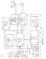
図3を参照すると、離れて位置決めされた皮膚スポットの電気的刺激とインピーダンス測定によって主に人間の臓器の病状の診断に使用するように意図された皮膚電気診断ユニット1が提供される。
【0038】
皮膚電気診断のユニット1において、制御ブロック2は、LCDディスプレイ37だけによって、あるいはビデオ表示ユニット13に接続されたビデオ・モニタまたUHF変調器ユニット10に接続されたテレビジョン・セットとの組み合わせによって、オペレータに指示を表示する。診断することができる臓器のリストが、モニタまたはテレビジョン・セットに表示される。オペレータは、キーパッド9によって診断する臓器を選択する。
【0039】
制御ユニット2は、調査する皮膚スポット/ゾーンの位置に基づいて診断方法を選択する。具体的には、交流測定(AC測定)または直流測定(DC測定)の2つの診断方法が使用可能である。AC測定は、足の裏などの厚い皮膚の領域に最も適する。DC測定は、耳などの薄い皮膚の領域に最も適する。
【0040】
制御ユニット2は、調査する領域(足や耳など)の絵を表示する。点滅しているゾーンまたはスポットは、オペレータが測定電極11.1を配置すべき場所を示す。制御ユニット2は、選択された検査を実行するために光リンクを介して電圧発生器ブロック5を制御する。
【0041】
DC測定の場合:電圧発生器ブロック5は、測定電極が基準電極に対して負の極性を有する状態で、測定電極11.1と基準電極11.3の間にわずかな一定の電位差を生成する。電流は、測定ブロック6を使用して制御ブロック2によって連続的に監視され、電流が事前に設定されたしきい値よりも高いとき両方のプローブが皮膚と接触していると想定される。プローブ間の電位差は、ゆっくり上昇し、プローブを流れる電流が連続的に測定される。皮膚の抵抗は、プローブに印加される電位の値をプローブに流れる被測定電流の値で割ることによって計算される。この抵抗の突然の大きい低下が検出されたとき(アルゴリズムについては図9を参照)、プローブ間の電位差が連続的に調整され、プローブを流れる被測定電流が所定のレベルに維持される。これは、皮膚の抵抗の変化率が所定のレベルより小さくなるまで続く。このときの電位差の値が、制御ブロック2によってデータ記憶ブロック3に記憶される。制御ブロック2は、電圧発生器ブロックを使用して、プローブ間に逆の極性で同じ電位差を印加する(測定電極が基準電極に対して正の極性にされる)。電流は、連続的に測定される。比率(被測定電流)/(事前設定された電流)は、特定の臓器の病状の程度を示すと考えられる。この比率が0に近い場合に、関連する臓器が病気であると考えられる。この比率が0.6よりも大きい場合は、関連する臓器が健康であると考えられる。この比率がゼロに近いほど臓器にある病状(たとえば癌)の程度が大きいと考えられる。
【0042】
制御ブロック2は、測定ブロック6により電流を監視し、オペレータがフット・ペダル12を押すまで、検査結果をLCDディスプレイ37に疾患の百分率目盛で表示する。制御ブロックは、検査結果をデータ記憶ブロック3に記憶し、ブザー36を鳴らして検査の完了を示す。
【0043】
AC測定の場合:オペレータは、LCDディスプレイ37によって要求されたときに被験者の皮膚に基準電極11.3と較正電極11.2を配置する。電圧発生器ブロック5は、電極11.2と11.3の間にわずかな一定の電位差を生成する。電流が連続的に監視され、事前設定されたしきい値よりも高いときに、両方のプローブが皮膚に接触していると想定される。次に、正弦交流電圧が電極間に印加される。電流が、測定ブロック6を使用して制御ブロック2によって連続的に監視され、電流が事前設定したレベルに達するまで電圧が調整される。このプロセスは、較正と呼ばれる。
【0044】
制御ユニット2は、結果表示ブロックを使用してビデオ・モニタまたはテレビ画面上に調査領域(一般に足)の画像を表示する。制御ユニット2は、測定電極11.1と基準電極11.3を現在使用すべきであることをオペレータに知らせるメッセージをLCDディスプレイ37に表示する。点滅するゾーンまたはスポットが、オペレータが測定電極11.1を配置すべき場所を示す。電流が連続的に測定される。比率(被測定電流)/(事前設定した電流)は、特定の臓器内の病状の程度を示すと考えられる。この比率が0に近い場合は、関連する臓器が病気であると考えられる。この比率が0.6よりも大きい場合は、関連した臓器が健康であると考えられる。この比率がゼロに近いほど臓器にある病状(たとえば癌)の程度が大きいと考えられる。制御ブロック2は、測定ブロック6により電流を監視し、オペレータがフット・ペダル12を押すまで、検査結果をLCDディスプレイ37上に疾患の百分率目盛で表示する。制御ブロックは、検査結果をデータ記憶ブロック3に記憶し、ブザー36を鳴らして検査の完了を示す。
【0045】
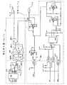
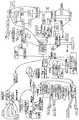
制御ユニット2は、マイクロコントローラ16で構成される(一般に8051)。発振器28は、マイクロコントローラ16にクロック信号を提供する。32KのRAM56と32KのROM57に接続する16ビット・アドレス・バス(11.1、16.3)を作成するために、標準的なアドレス・ラッチ(11)構成が使用される。双方向データバス16.1が、マイクロ・コントローラ16との間でデータを送る。マイクロコントローラ16は、キーパッド・インタフェース17を使用してキーパッド9とインタフェースをとる(一般に、74HC922)。
【0046】
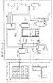
電極は、電圧発生器ブロック5内の変圧器43.1により主回路から直流電気的に分離される55。測定ブロック6は、光結合素子51、52、53、54によって主回路から光学的に切り離される。変圧器43の一次コイルに印加される正弦波電圧は、第2のコイル43.2によって段階的に高められる。電圧倍増回路44は、キャパシタ38に一定電圧が現われるようにコイル43.2の正弦波出力を2倍にし整流する。リレー40がオフのとき、交流電圧がリレー42に送られる。リレー40がオンのとき、 キャパシタ38上の一定電圧がリレー42に送られる。リレー42は、リレー40からの信号の極性を切り替えるために使用される。このリレー42と40の組合せは、プローブ間の電圧を交流電圧または一定電圧に設定するために使用され、プローブの極性を逆にすることを可能にする。
【0047】
変圧器43の一次コイル43.1は、反転器増幅器モードで使用される演算増幅器41によって駆動される。プログラム可能な正弦波発生器39(一般にML2036)は、演算増幅器41に入力信号を提供する。正弦波発生器39は、ライン22.1、22.3、22.4を介してマイクロコントローラ16によって制御される。周波数は、このシリアル・バスを介してデジタル的にプログラムされる。正弦波信号の振幅(ピーク・ツー・ピークの半分)は、デジタル・アナログ変換器24の出力24.1の振幅と等しい。デジタル・アナログ変換器24の出力電圧は、バス16.1を介してマイクロコントローラ16によって設定される。
【0048】
電流は、測定ブロック6を使用して測定される。電極間の回路が人体などのインピーダンスにより閉じられると、測定抵抗器46を介して電極からアースに電流が流れる。したがって、この抵抗器にアースに対して現われる電圧は、プローブを流れる電流に比例する。演算増幅器バッファ45が、符号47と48で示した演算増幅器によって形成された信号を高精度整流器に送る。これらは、直列のアナログ・デジタル変換器(ADC)49に送られる信号の絶対値を抽出する。ADC49は、3つの光結合素子52、53、54によって提供される光リンクを介してライン22.1、22.2および22.3からなるシリアル・バスを介してマイクロコントローラ16と通信する。ゼロ交差検出器50は、測定抵抗器46上の電圧の極性を検出し、その情報を、2進法の0または1の情報として、光結合素子51を通じてマイクロコントローラ16に送る。交流電圧が電極に印加されるとき、すべての電圧ピークにおける電流が測定される。マイクロコントローラ16は、光結合素子51の出力22.5が0から1に遷移するのを待つ。マイクロコントローラ16は、出力電圧周波数の4分の1に等しい期間だけ待った後でアナログ・デジタル変換器49からの変換を要求する。
【0049】
マイクロコントローラは、ビデオ表示ユニット13によりモニタ上に関連情報を表示する。デュアル・ポートRAM30は、スクリーンのビット・マップ・バージョンを含む。マイクロコントローラ16は、制御線16.6および16.7、ならびに符号11.1と16.3で示したアドレス・バスを使用して、データ・バス16.1を介してデュアル・ポートRAM30に対してデータを読み書きすることができる。フィールド・プログラマブル・ゲート・アレイ(FPGA)25は、カウンタとシフト・レジスタを使用して、スクリーン・データのバイトを読み取って赤、緑および青(RGB)の画素情報と垂直および水平帰線情報をRGB−PALエンコーダ31に書き込む。ユニバーサル同期発生器33は、PALビデオ標準同期パルスを生成する。そのようなパルスは、フェイズロックループ34を使用して主システム・クロックにロックされる。画素クロックは、FPGA25内のカウンタを使用して主システム・クロック16.5から得られる。画素クロックは、デュアル・ポートRAM30からデータを適切なレートと適切な方法で読み取ってシリアル化するために使用され、それによりRBG−PALエンコーダに送られたビット・ストリームを、標準ビデオ・モニタのビデオ入力31.1に直接送ることができるPAL標準複合同期ビデオ信号にエンコードすることができる。
【0050】
UHF変調器ユニット10は、複合同期ビデオ信号を、テレビジョン・セットのアンテナ・ポート35.1に直接送ることができる極超短波信号に変換する。統合されたUHF変調器35は、ビデオ表示ユニットから複合同期PAL信号を、外部構成要素によって決定される周波数に変調する。
【0051】
電源ブロック4によって回路に電力が送られる。一次結合が幹線に結合され二次結合が整流器ブリッジ14.2に接続された変圧器14.1は、幹線220VACを7.2VACに変換する。整流器の出力は、5Vレギュレータ14.3に送られる。一体式電圧反転器15.1(一般にMAX66O)は、幹線5V電源から−5V電源を生成する。
【0052】
電圧発生器ブロック5と測定ブロック6に提供された電力は、主電源から直流電気的に分離される。DC/DCコンバータ15.2(一般にNMAO505)は、分離された患者インタフェース回路に+5Vと−5Vを提供するために使用される。
【0053】
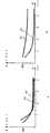
図10は、ブレークスルー効果(x)が達成されたときのある期間の電圧のグラフを示す。ブレークスルーの点(x)において、抵抗の急激で大きい低下が生じ、それにより電圧の急激で大きい低下が観察される。ブレークスルー効果の後で電圧が安定してから基準値が測定される。
【0054】
図11aと図11bは、臓器に疾患があるときに抵抗にどのように影響するかを示す。図11aにおいて、2つの曲線は、健康な臓器の異なる電圧における抵抗値を表し、図11bは、病気の臓器の様々な電圧における2つの抵抗値の曲線を示す。線50は、基準抵抗値を表し、線52は、測定抵抗値を表す。図11bは、病気の臓器の様々な電圧における2つの抵抗値の曲線を示す。臓器が健康なとき、基準抵抗値と測定抵抗値は類似しているが、臓器の疾患の状態が高まるにつれて、測定値が大きくなり、基準値と測定値との差が大きくなる。
【0055】
同様に、図12は、臓器が病気のときに測定インピーダンスがどのように変化するかを示す。線56は、様々な周波数における基準値または抵抗値を示す。線58は、健康な臓器の測定抵抗値を示し、線60は、病気の臓器の測定抵抗値を示す。臓器が病気になるほど測定抵抗値が大きくなり、したがってより測定値と基準値の差が大きくなる。
【0056】
図13と図14を参照すると、特定の臓器を診断するために示されたスポットのうちの1つに測定電極または較正電極が配置される。
【0057】
電極を配置するスポットは、特定の臓器に依存し、以下に示した表1と表2は、番号を付けたスポットが指す臓器を示す。
【0058】
【表1】
【表2】
【図面の簡単な説明】
【図1】 図1は、本発明により広義にDCまたはAC測定法を使用して皮膚のインピーダンスの差違と対応する臓器の健康状態とを評価する装置を概略的なブロック図である。
【図2】 図2は、本発明により広義にDCまたはAC測定方法を使用して皮膚のインピーダンスの差違とそれに対応する臓器の健康状態とを評価する装置の代替実施形態を概略的なブロック図である。
【図3】 図3は、本発明によるDCまたはAC測定法を使用して皮膚のインピーダンスとそれに対応する臓器の健康状態とを評価する装置を概略的なブロック図である。
【図4】 図4は、図3による電源ユニットを示す回路図である。
【図5】 図5は、図3による制御ブロックとユーザ・インタフェース・ブロックを示す回路図である。
【図6】 図6は、図3による結果表示ブロックを示す回路図である。
【図7】 図7は、図3による電圧発生器ブロックと測定ブロックを示す回路図である。
【図8】 図8は、図3によるデータ記憶ブロックを示す回路図である。
【図9】 図9は、図5の制御ブロック内のマイクロコントローラに使用されるソフトウェアの簡略化した流れ図である。
【図10】 図10は、本発明の装置をDC測定モードで使用して得られたブレークスルー効果を示す図である。
【図11】 図11は、DC測定法を使用する本発明の技術を適用したときに得られる健康な臓器に対応する皮膚スポット(図11a)と病気の臓器(図11b)に対応する皮膚スポットの印加電圧に対する皮膚抵抗の依存性をグラフで示す図である。
【図12】 図12は、AC測定法を使用する本発明の技術を適用したときの印加周波数に対する皮膚インピーダンスの依存性をグラフで示す図である。
【図13】 図13は、臓器に対応する人間の耳介の皮膚スポットを示す図である。
【図14】 図14は、特定の臓器に対応する人間の足の裏の皮膚ゾーンを示す図である。(Technical field)
The present invention relates to an apparatus and method for automatically evaluating skin impedance in order to estimate the health of human or animal internal organs.
[0001]
(Background technology)
The existing methods for diagnosing organs using skin impedance values are based on very basic skin impedance measurement results based on non-ratio measurements, such as patient emotional state, muscle tension, measurement time, and contact. There will be inconsistent and unreliable results that depend on a number of variables including area and pressure of the measuring electrode and various physiological differences between individuals.
[0002]
As a result of many years of research, the inventor has now responded to human or animal body organs that can derive information about the corresponding body organs by measuring the electrical properties of the skin. I am convinced that the area is equipped. Furthermore, the inventor believes that the corresponding area of the skin is associated with the science of reflex physiotherapy (including acupuncture), eg the ability to heal and / or alleviate pain caused by the corresponding organ. Other characteristics are also provided.
[0003]
Furthermore, the inventor believes that these corresponding skin regions can be mapped, and the maps can be applied to different individuals.
[0004]
According to the inventor's discovery, the pinna can be mapped particularly accurately, and in most cultures the ear skin is exposed and can be examined without the need to take off clothes. It is most suitable for the method of the present invention.
[0005]
In this specification, the term “impedance” should be understood to include resistance unless the context clearly indicates otherwise.
[0006]
(Disclosure of the Invention)
Impedance variation can be measured in two ways.
[0007]
Method 1: AC evaluation
Using the difference between the AC impedance measured at a specific frequency and specific skin area using a calibration electrode and a reference electrode, and the impedance measured at the same frequency and same area using the measurement electrode and reference electrode The health condition of the internal organs corresponding to the skin area to be examined is determined. The contact area between the calibration electrode and the reference electrode is relatively wider than the skin contact area of the measurement electrode.
[0008]
Method 2: DC evaluation
The term “break through effect” refers to the sudden and significant reduction in skin electrical resistance seen after a sufficient potential difference is applied between the electrodes.
[0009]
The skin between the electrodes is exposed to a DC potential of a magnitude selected to produce a breakthrough effect. The DC resistance of the skin is measured between a measuring electrode that is given a negative polarity with respect to the reference electrode, and the DC resistance of the same skin area is again, but positively given to the reference electrode Measured by a measuring electrode. The ratio of these two values is used to determine the health state of the internal organ corresponding to the skin area under examination.
[0010]
In general, the device according to the invention can include the following functional blocks:
Measurement and / or calibration electrodes, reference electrodes, voltage generation block, measurement block, control block, user interface block, result presentation block, and optionally data storage block.
[0011]
The voltage generation block generates a potential difference between the measurement electrode and the reference electrode or between the calibration electrode and the reference electrode. The voltage generation block is connected to and controlled by the control block. The measurement block is connected to the measurement electrode and the reference electrode (FIG. 1).
[0012]
The measurement block measures the impedance between the measurement electrode and the reference or calibration electrode. As an alternative, the voltage generation block can also be connected to the measurement electrode or the reference electrode via the measurement block (FIG. 2). The ultimate purpose of the measurement block is to measure parameters (such as voltage or current) that can be used to determine the impedance or resistance between the measurement electrode and the reference electrode. The measurement block is connected to the control block.
[0013]
The control block is connected to a user interface block (if any), a data storage block (if any), a result presentation block, a voltage generation block, and a measurement block. The control block sets the voltage generated by the voltage generation block. The control block uses the information received from the measurement block to detect breakthrough effects and resistance asymmetry. The control block can store and read information in the data storage block (if any). The control block informs the user of the measurement result via the result presentation block. The result presentation block can generate a visual or audio display to inform the user of the result, i.e. the health of the internal organs obtained by the control block.
[0014]
Explanation of operation
After many experimental studies, the inventor has found that in order to obtain reliable results, the broad apparatus according to the present invention can be operated as shown below.
[0015]
Method 1: AC evaluation
The calibration electrode is placed in contact with the relevant skin area corresponding to the organ of the subject whose health status is to be determined. The reference electrode is placed in contact with some other skin region (usually the subject's hand). The control block uses the voltage generator block to generate an AC signal of a specific frequency and amplitude between the calibration electrode and the reference electrode. The control block determines the impedance between the electrodes by the measurement block. The control block stores its impedance value in the data storage block (referred to as “calibration impedance”). The control block issues a signal indicating that the calibration impedance has been determined by the result display block. The calibration electrode is removed and the measurement electrode is placed in the skin area to be examined. The control block uses the voltage generator block to generate an AC signal of the same frequency and amplitude between the calibration electrode and the reference electrode.
[0016]
The control block determines the ratio between the calibration impedance and the impedance measured with the measurement electrode and converts the ratio into an indication of the health of the organ. The control block displays the result on a result display block (eg, disease intensity percentage scale).
[0017]
This result is conveniently displayed in the form of a percentage calculated by the following equation:
[0018]
% Disease = (1-I measurement / I criteria) x 100, or
% Disease = (1-R reference / R measurement) x 100
Different percentage ranges correspond to the health of the organs. In general, 0 to 40% indicates the health state of the organ concerned, 40 to 60% indicates the upper limit of the health state, 60 to 80% indicates the subacute state, and 80 to 100% indicates the acute state. Indicates.
[0019]
Method 2: DC evaluation
The reference electrode is placed in contact with any skin area. The measurement electrode is placed in contact with a specific skin portion corresponding to the organ that determines the health condition. The control block uses a voltage generator block to generate a DC potential difference between the electrodes. The control block determines the resistance between the electrodes by the measurement block. The control block adjusts the DC potential difference and examines the resistance until the resistance falls below a certain threshold or suddenly begins to drop rapidly (breakthrough effect). The control block examines the resistance until a stable value is obtained. The control block stores the resistance value in the data storage block (referred to as “reference resistance”).
[0020]
The control block inverts the polarities of the measurement electrode and the reference electrode and applies a DC potential to both sides of the electrode using the voltage generator block. The control block determines the resistance between the electrodes by the measurement block (referred to as “measurement resistance”).
[0021]
The control block determines the ratio of “measured resistance” and “reference resistance” and calculates the intensity of the disease from this ratio. The following formula is used for the calculation.
[0022]
% Disease = (1-I measurement / I criteria) x 100, or
% Disease = (1-I criteria / R measurement) x 100
The control block displays this result on the result display block (eg, on a disease intensity percentage scale).
[0023]
The results are conveniently displayed in the form of percentages with a range of percentages that vary depending on the health of the organ. In general, 0 to 40% indicates the health state of the organ, 40 to 60% indicates the upper limit of the health state, 60 to 80% indicates the subacute state, and 80 to 100% indicates the acute state. Show.
[0024]
When the induction of the breakthrough effect is the best, the reference resistance is measured by a measurement electrode having a negative polarity with respect to the reference electrode. However, if the potential difference between the electrodes is large, the breakthrough occurs when the polarity is reversed. It is thought that an effect may be observed.
[0025]
When using the DC method, if the organ is not healthy, the measurement electrode having a positive polarity relative to the reference electrode is measured to have a higher resistance than the measurement electrode having a negative polarity relative to the reference electrode (e.g. , 300 kΩ for 30 kΩ). Similarly, when using the AC method, the measurement obtained using the measurement electrode exhibits a higher impedance than the measurement obtained using the calibration electrode.
[0026]
AC signals can also be used when using the DC method.
[0027]
Although the AC method and the DC method are both effective for thin skin areas such as the auricle, the DC evaluation method is preferred. For thick skin parts of the body, such as the feet, the AC method is preferred in order to avoid pain in the subject, as the thick skin area requires a high voltage to produce a breakthrough effect.
[0028]
The present inventor uses a new measurement method and a proportional measurement method, and the device as described above is not affected by various physiological differences among individuals, patient emotional state, muscle tone and measurement time. We expect to achieve consistent and reproducible diagnostic results. The result depends on the intensity of the disease and the effect of pressure is very small.
[0029]
Example
Example 1:
In the first test diagnosed with gastric ulcer, the following results were obtained.
[0030]
Auricular projection area (thin skin-DC measurement): reference resistance = 10 kΩ,
Stomach projection area: measurement resistance = 200 kΩ
Ie 95% of disease states
Healthy organ projection area: Measurement resistance = 10 to 25 kΩ
That is, 0-60% of disease states
Foot projection area (thick skin-AC measurement): Reference resistance = 15 kΩ (at 250 Hz)
Stomach projection area: Measurement resistance = 300 kΩ
Ie 95% of disease states
Healthy organ projection area: measurement resistance = 15-37.5 kΩ
That is, 0-60% of disease states
Example 2:
Pyelonephritis (kidney infection)
Auricular projection area (thin skin-DC measurement): Reference resistance = 10 kΩ
Kidney projection area: measurement resistance = 100 kΩ
Ie 90% of disease states
Healthy organ projection area: Measurement resistance = 10 to 25 kΩ
That is, 0-60% of disease states
Pedal projection area (thick skin-AC measurement): Reference resistance = 10 kΩ (at 250 Hz)
Kidney projection area: measurement resistance = 100 kΩ
Ie 90% of disease states
Healthy organ projection area: Measurement resistance = 10 to 25 kΩ
That is, 0-60% of disease states
[0031]
In the figure,
[0032]
The
[0033]
In FIG. 2, reference numeral 1.2 broadly represents an alternative device for determining the health state of a subject's organ by the broad sense impedance fluctuation evaluation method according to the present invention.
[0034]
The
[0035]
The
[0036]
The
[0037]
Referring to FIG. 3, there is provided an electrocutaneous
[0038]
In the electrocutaneous
[0039]
The
[0040]
The
[0041]
For DC measurement: the
[0042]
The
[0043]
For AC measurements: The operator places the reference electrode 11.3 and the calibration electrode 11.2 on the subject's skin when required by the
[0044]
The
[0045]
The
[0046]
The electrodes are galvanically separated from the
[0047]
The primary coil 43.1 of the transformer 43 is driven by the
[0048]
The current is measured using the
[0049]
The microcontroller displays related information on the monitor by the
[0050]
The
[0051]
Power is sent to the circuit by the
[0052]
The power provided to the
[0053]
FIG. 10 shows a graph of the voltage over a period when the breakthrough effect (x) is achieved. At the breakthrough point (x), a rapid and large drop in resistance occurs, whereby a rapid and large drop in voltage is observed. The reference value is measured after the voltage has stabilized after the breakthrough effect.
[0054]
Figures 11a and 11b show how resistance is affected when an organ is diseased. In FIG. 11a, the two curves represent the resistance values at different voltages of the healthy organ, and FIG. 11b shows the curves of the two resistance values at various voltages of the diseased organ.
[0055]
Similarly, FIG. 12 shows how the measured impedance changes when the organ is ill.
[0056]
Referring to FIGS. 13 and 14, a measurement or calibration electrode is placed in one of the spots shown for diagnosing a particular organ.
[0057]
The spot where the electrode is placed depends on the specific organ, and Tables 1 and 2 shown below show the organ pointed to by the numbered spot.
[0058]
[Table 1]
[Table 2]
[Brief description of the drawings]
FIG. 1 is a schematic block diagram of an apparatus for assessing skin impedance differences and corresponding organ health using DC or AC measurement methods broadly according to the present invention.
FIG. 2 is a schematic block diagram of an alternative embodiment of an apparatus for assessing skin impedance differences and corresponding organ health using DC or AC measurement methods broadly in accordance with the present invention. It is.
FIG. 3 is a schematic block diagram of an apparatus for assessing skin impedance and corresponding organ health using a DC or AC measurement method according to the present invention.
4 is a circuit diagram showing the power supply unit according to FIG. 3. FIG.
FIG. 5 is a circuit diagram showing a control block and a user interface block according to FIG. 3;
6 is a circuit diagram showing a result display block according to FIG. 3;
7 is a circuit diagram showing a voltage generator block and a measurement block according to FIG. 3;
FIG. 8 is a circuit diagram showing a data storage block according to FIG. 3;
FIG. 9 is a simplified flow diagram of software used for the microcontroller in the control block of FIG.
FIG. 10 is a diagram showing the breakthrough effect obtained using the apparatus of the present invention in the DC measurement mode.
FIG. 11 shows a skin spot corresponding to a healthy organ (FIG. 11a) and a skin spot corresponding to a diseased organ (FIG. 11b) obtained when the technique of the present invention using a DC measurement method is applied. It is a figure which shows the dependence of the skin resistance with respect to the applied voltage of a graph.
FIG. 12 is a graph showing the dependence of skin impedance on the applied frequency when the technique of the present invention using the AC measurement method is applied.
FIG. 13 is a diagram showing a skin spot of a human pinna corresponding to an organ.
FIG. 14 is a diagram showing a skin zone on the sole of a human foot corresponding to a specific organ.
Claims (8)
Translated fromJapanese少なくとも2つの電極を接続することが可能な電気信号発生手段と、
第1の前記電極を前記器官に対応する第1の皮膚ゾーンに接触させ、第2の前記電極を同じ身体の第2の皮膚ゾーンに接触させ、前記第1及び第2の電極間に直流電位差を加えて、前記第1及び第2の電極間の抵抗によって決まる少なくとも第1のパラメータをモニタし測定する手段と、
ブレーク・スルー電位差における皮膚抵抗の低下による前記第1のパラメータの変化が生じるまで前記電位差を調整する手段と、
前記ブレーク・スルー電位差に達した後まで、前記第1のパラメータの第1の測定値を記録するように構成された記録手段と、
前記第1の測定値が記録された後、前記第1及び第2の電極の極性が反転するように、前記第1及び第2の電極間の電位差を変化させる手段と、
前記第1及び第2の電極の極性反転後、前記第1及び第2の電極間の抵抗によって決まる第2のパラメータの第2の測定値を記録するように構成された記録手段と、
前記第1と第2の測定値を比較して、前記第1の皮膚ゾーンが対応する前記器官の健康状態の指標である第3の値を得る手段と、
を有する装置。A device for diagnosing the health of an organ of a human or animal body,
Electrical signal generating means capable of connecting at least two electrodes;
The first electrode is brought into contact with a first skin zone corresponding to the organ, the second electrode is brought into contact with a secondskin zone of the same body, and adirect current potential difference between the first and second electrodes. It was added, andwherein the means for monitoring at least a first parameterin the resistance thus determinedbetween the first and second electrode measuring,
It means for adjusting the potential difference until the change inthe firstparameter due to a reduction in skinresistance at breakthrough potential difference occurs,
Untilafter reached the breakthrough potential difference, and configured recording device to record first measurement value of the first parameter,
Means for changing a potential difference between the first and second electrodes so that the polarities of the first and second electrodes are reversed after the first measurement value is recorded;
A recording means configured to record a second measured value of a second parameter determined by a resistance between the first and second electrodes after polarity reversal of the first and second electrodes;
Means for obtaining the first and by comparing the second measurement,the first third value skin zone is indicative of the health condition of the corresponding organ,
Having a device.
Applications Claiming Priority (3)
| Application Number | Priority Date | Filing Date | Title |
|---|---|---|---|
| ZA98/5900 | 1998-07-06 | ||
| ZA985900 | 1998-07-06 | ||
| PCT/ZA1999/000048WO2000001301A1 (en) | 1998-07-06 | 1999-07-06 | Apparatus for evaluation of skin impedance variations |
Publications (3)
| Publication Number | Publication Date |
|---|---|
| JP2003510105A JP2003510105A (en) | 2003-03-18 |
| JP2003510105A5 JP2003510105A5 (en) | 2006-07-20 |
| JP4325969B2true JP4325969B2 (en) | 2009-09-02 |
Family
ID=69374665
Family Applications (1)
| Application Number | Title | Priority Date | Filing Date |
|---|---|---|---|
| JP2000557751AExpired - Fee RelatedJP4325969B2 (en) | 1998-07-06 | 1999-07-06 | Skin impedance fluctuation evaluation device |
Country Status (16)
| Country | Link |
|---|---|
| US (2) | US6633777B2 (en) |
| EP (1) | EP1094749B1 (en) |
| JP (1) | JP4325969B2 (en) |
| KR (1) | KR100584114B1 (en) |
| CN (1) | CN1173665C (en) |
| AT (1) | ATE286673T1 (en) |
| AU (1) | AU759937B2 (en) |
| BR (1) | BR9911866A (en) |
| CA (1) | CA2336825C (en) |
| DE (1) | DE69923183T2 (en) |
| HK (1) | HK1041189B (en) |
| ID (1) | ID29282A (en) |
| IL (1) | IL140719A (en) |
| RU (1) | RU2249431C2 (en) |
| WO (1) | WO2000001301A1 (en) |
| ZA (1) | ZA200100970B (en) |
Families Citing this family (68)
| Publication number | Priority date | Publication date | Assignee | Title |
|---|---|---|---|---|
| AUPQ113799A0 (en) | 1999-06-22 | 1999-07-15 | University Of Queensland, The | A method and device for measuring lymphoedema |
| EP1811296A1 (en)* | 2000-08-23 | 2007-07-25 | Shiseido Company, Limited | Methods and apparatus for measuring skin surface condition |
| DE10125359B4 (en)* | 2001-05-23 | 2005-07-28 | Osypka Medical Gmbh | An AC power source for generating an AC current to be transmitted through the body and a method of generating a stable AC current |
| US6823212B2 (en)* | 2001-06-13 | 2004-11-23 | The Procter & Gamble Company | Method and apparatus for measuring properties of a target surface |
| DE60223548T2 (en)* | 2001-07-06 | 2008-10-23 | Aspect Medical Systems, Inc., Newton | SYSTEM AND METHOD FOR MEASURING BIOELECTRIC RESISTANCE IN THE EVENT OF INTERFERENCE |
| US7822470B2 (en)* | 2001-10-11 | 2010-10-26 | Osypka Medical Gmbh | Method for determining the left-ventricular ejection time TLVE of a heart of a subject |
| NO321659B1 (en)* | 2002-05-14 | 2006-06-19 | Idex Asa | Volume specific characterization of human skin by electrical immitance |
| US8594764B2 (en)* | 2003-03-07 | 2013-11-26 | Jon Rice | Device and method for assessing the electrical potential of cells and method for manufacture of same |
| US20040204658A1 (en)* | 2003-04-10 | 2004-10-14 | Dietz Phillip W. | Systems and methods for providing an enhanced bioelectric sensing surface |
| JP4387125B2 (en)* | 2003-06-09 | 2009-12-16 | 東京エレクトロン株式会社 | Inspection method and inspection apparatus |
| DE10332820B4 (en)* | 2003-07-18 | 2006-07-20 | Osypka Medical Gmbh | Device for electrically converting a first voltage into a second voltage for measuring impedances and admittances on biological tissues |
| KR100580629B1 (en)* | 2003-11-17 | 2006-05-16 | 삼성전자주식회사 | Skin impedance model that expresses skin impedance response of high frequency band |
| GB2414407B (en)* | 2004-05-28 | 2009-04-15 | Eumedic Ltd | Treatment apparatus for applying electrical impulses to the body of a patient |
| US8744564B2 (en) | 2004-06-18 | 2014-06-03 | Impedimed Limited | Oedema detection |
| US7937139B2 (en)* | 2004-07-20 | 2011-05-03 | Biomeridian International, Inc. | Systems and methods of utilizing electrical readings in the determination of treatment |
| WO2006056074A1 (en)* | 2004-11-26 | 2006-06-01 | Z-Tech (Canada) Inc. | Weighted gradient method and system for diagnosing disease |
| RU2285492C2 (en)* | 2004-12-21 | 2006-10-20 | Мария Юрьевна Шарафутдинова | Device for cold radio-frequency ablation |
| US20110054343A1 (en) | 2005-07-01 | 2011-03-03 | Impedimed Limited | Monitoring system |
| EP2460468A1 (en)* | 2005-07-01 | 2012-06-06 | Impedimed Limited | Monitoring system |
| WO2007014417A1 (en) | 2005-08-02 | 2007-02-08 | Impedimed Limited | Impedance parameter values |
| DE602005004282T2 (en) | 2005-08-17 | 2008-11-27 | Osypka Medical Gmbh | Digital demodulation apparatus and method for measuring electrical bioimpedance or bioadmittance |
| WO2007026335A2 (en)* | 2005-09-02 | 2007-03-08 | The Procter & Gamble Company | Methods for measuring moisture content of skin |
| CN101252879A (en)* | 2005-09-02 | 2008-08-27 | 宝洁公司 | Effective Predictor of Scalp Health |
| WO2007026337A2 (en)* | 2005-09-02 | 2007-03-08 | The Procter & Gamble Company | Methods for retail measurement of skin moisture content |
| EP1919358A2 (en)* | 2005-09-02 | 2008-05-14 | The Procter and Gamble Company | Method and device for indicating moisture content of skin |
| WO2007026340A2 (en)* | 2005-09-02 | 2007-03-08 | The Procter & Gamble Company | Methods for measuring moisture as a predictor of scalp health |
| JP5208749B2 (en) | 2005-10-11 | 2013-06-12 | インペダイムド・リミテッド | Hydration status monitoring |
| CN101400860A (en)* | 2005-12-15 | 2009-04-01 | 特拉富申股份有限公司 | Soil stabilization |
| AU2007266311B2 (en) | 2006-05-30 | 2014-01-30 | Impedimed Limited | Impedance measurements |
| KR101213157B1 (en)* | 2006-06-09 | 2012-12-17 | 삼성전자주식회사 | Sensor for measuring skin impedence |
| KR100756409B1 (en)* | 2006-07-05 | 2007-09-10 | 삼성전자주식회사 | Skin hydration measuring device and method |
| WO2008007638A1 (en)* | 2006-07-10 | 2008-01-17 | Panasonic Corporation | Skin conductivity measuring device |
| ES2324189B1 (en)* | 2006-10-03 | 2010-05-13 | Consejo Superior Investig. Cientificas | DEVICE FOR THE DIAGNOSIS AND MONITORING OF HEPATIC ESTEATOSIS BASED ON THE MEASUREMENT OF ELECTRICAL IMPEDANCE. |
| AU2007327573B2 (en) | 2006-11-30 | 2013-07-18 | Impedimed Limited | Measurement apparatus |
| CA2675438A1 (en) | 2007-01-15 | 2008-07-24 | Impedimed Limited | Monitoring system |
| CA2703361C (en) | 2007-03-30 | 2016-06-28 | Impedimed Limited | Active guarding for reduction of resistive and capacitive signal loading with adjustable control of compensation level |
| WO2008128281A1 (en) | 2007-04-20 | 2008-10-30 | Impedimed Limited | Monitoring system and probe |
| AU2008324750B2 (en) | 2007-11-05 | 2014-01-16 | Impedimed Limited | Impedance determination |
| TWI386200B (en)* | 2007-12-21 | 2013-02-21 | Method of identifying points | |
| US8682425B2 (en)* | 2008-01-30 | 2014-03-25 | Miridia Technology Inc. | Electroacupuncture system |
| AU2008207672B2 (en) | 2008-02-15 | 2013-10-31 | Impedimed Limited | Impedance Analysis |
| US20110071419A1 (en)* | 2008-05-26 | 2011-03-24 | Koninklijke Philips Electronics N.V. | Location indicating device |
| US9615766B2 (en) | 2008-11-28 | 2017-04-11 | Impedimed Limited | Impedance measurement process |
| US9050016B2 (en)* | 2009-02-10 | 2015-06-09 | Siemens Medical Solutions Usa, Inc. | System for heart performance characterization and abnormality detection |
| KR100897002B1 (en) | 2009-02-11 | 2009-05-14 | 문준호 | Medical diagnostic devices |
| EP2305112A1 (en)* | 2009-10-01 | 2011-04-06 | seca ag | Bioimpedance measuring device |
| US9615767B2 (en) | 2009-10-26 | 2017-04-11 | Impedimed Limited | Fluid level indicator determination |
| CA2778770A1 (en) | 2009-11-18 | 2011-05-26 | Chung Shing Fan | Signal distribution for patient-electrode measurements |
| US8670832B2 (en)* | 2010-08-10 | 2014-03-11 | Igor Raykhman | System and methods for producing and delivering electrical impulses |
| US20120041332A1 (en)* | 2010-08-11 | 2012-02-16 | Georgiy Lifshits | Device and method for oriental medicine diagnosis and treatment |
| CN102445602A (en)* | 2011-09-30 | 2012-05-09 | 广东省疾病预防控制中心 | In-vitro skin transcutaneous electrical resistance measuring device |
| US8781565B2 (en) | 2011-10-04 | 2014-07-15 | Qualcomm Incorporated | Dynamically configurable biopotential electrode array to collect physiological data |
| CN102512169B (en)* | 2011-12-31 | 2013-06-05 | 重庆邮电大学 | Adaptive control method and device for deviation in skin electrical signal testing |
| US20130317318A1 (en)* | 2012-05-25 | 2013-11-28 | Qualcomm Incorporated | Methods and devices for acquiring electrodermal activity |
| CN102727197B (en)* | 2012-06-14 | 2015-02-18 | 深圳市元征科技股份有限公司 | Cell activity detection method |
| CN102727183A (en)* | 2012-06-14 | 2012-10-17 | 深圳市元征科技股份有限公司 | Device for detecting cell vigor |
| RU2528075C2 (en)* | 2012-11-08 | 2014-09-10 | Федеральное Государственное Бюджетное Образовательное Учреждение Высшего Профессионального Образования Рязанский Государственный Радиотехнический Университет | Method for real-time electrodermal skin activity test and device for implementing it |
| US9378655B2 (en) | 2012-12-03 | 2016-06-28 | Qualcomm Incorporated | Associating user emotion with electronic media |
| DE102014015896A1 (en)* | 2014-10-28 | 2016-04-28 | Drägerwerk AG & Co. KGaA | Device for detecting electrical potentials |
| FR3028744A1 (en) | 2014-11-25 | 2016-05-27 | Impeto Medical | ELECTROPHYSIOLOGICAL DATA COLLECTION DEVICE WITH INCREASED RELIABILITY |
| DE102016001080A1 (en) | 2015-02-09 | 2016-08-11 | Stefan Liebelt | Method and diagnostic device for the determination of cancer in the human body due to the higher iron concentration of malignant cells |
| EP3494869B1 (en)* | 2017-12-11 | 2021-01-27 | Stichting IMEC Nederland | An electronic system and method for bioimpedance signal acquisition |
| EP3553538B1 (en) | 2018-04-13 | 2021-03-10 | Nokia Technologies Oy | An apparatus, electronic device and method for estimating impedance |
| CN109222934B (en)* | 2018-10-30 | 2019-06-28 | 北京康加科技有限公司 | System and method for bio-electrical impedance coherence measurement |
| KR102264402B1 (en)* | 2019-02-21 | 2021-06-14 | 주식회사 바이랩 | Measuring device using eit electrode |
| RU2770291C2 (en)* | 2020-10-12 | 2022-04-15 | Общество с ограниченной ответственностью "БИСЕНС" | Method for taking signals for assessment of person's emotional reaction using headphones |
| KR20230018080A (en)* | 2021-07-29 | 2023-02-07 | 삼성전자주식회사 | Electronic device for measuring biometric information and operation method thereof |
| FR3131521B1 (en)* | 2021-12-31 | 2024-10-25 | Withings | Measuring station with measurement of sweat activity |
Family Cites Families (17)
| Publication number | Priority date | Publication date | Assignee | Title |
|---|---|---|---|---|
| US3971366A (en)* | 1974-11-25 | 1976-07-27 | Hiroshi Motoyama | Apparatus and method for measuring the condition of the meridians and the corresponding internal organs of the living body |
| US4016870A (en)* | 1975-10-14 | 1977-04-12 | Chuck Lock | Electronic acupuncture point finder |
| US4160447A (en)* | 1976-05-20 | 1979-07-10 | Stanley Electric Co., Ltd. | Device for detecting particular point of human body |
| US4557271A (en)* | 1983-05-11 | 1985-12-10 | Stoller Kenneth P | Method and apparatus for detecting body illness, dysfunction, disease and/or pathology |
| JPS62324A (en)* | 1985-06-27 | 1987-01-06 | 本山 博 | Apparatus for diagnosis of internal organs and nerval function |
| US5678547A (en)* | 1988-12-22 | 1997-10-21 | Biofield Corp. | Method and apparatus for screening or sensing bodily conditions using DC biopotentials |
| US5069223A (en)* | 1990-02-14 | 1991-12-03 | Georgetown University | Method of evaluating tissue changes resulting from therapeutic hyperthermia |
| RU2029493C1 (en)* | 1992-02-28 | 1995-02-27 | Спиридонов Владимир Афанасьевич | Method of diagnostics of human organism state according to characteristics of biologically active points and apparatus for performing the method |
| US5339827A (en)* | 1993-02-11 | 1994-08-23 | Intech Scientific, Inc. | Acupuncture system and method |
| US5409011A (en)* | 1993-07-07 | 1995-04-25 | Alexeev; Vassili | Bioenergy assessing method and system for diagnosing and providing therapy |
| JP2510401B2 (en)* | 1994-01-10 | 1996-06-26 | 有限会社東洋医学 | Acupuncture device using high frequency |
| US5732710A (en)* | 1996-08-09 | 1998-03-31 | R.S. Medical Monitoring Ltd. | Method and device for stable impedance plethysmography |
| US5772605A (en)* | 1996-12-18 | 1998-06-30 | Medtronic, Inc. | System and method for detecting facial symmetry |
| RU2126675C1 (en)* | 1998-01-05 | 1999-02-27 | Уральский государственный институт ветеринарной медицины | Method of diagnostics of dog's liver diseases |
| DE19911200A1 (en)* | 1999-03-13 | 2000-09-21 | Bruno M Hess | Device for measurement of bio-electric parameters such as voltage and resistance of skin or tissue between acupuncture points in a human or animal has opposite polarity constant current sources and measurement electrodes |
| US6285905B1 (en)* | 1999-06-24 | 2001-09-04 | Chih-Cheng Chiang | Two-way medical treatment apparatus |
| RU2194490C1 (en)* | 2001-10-29 | 2002-12-20 | Общество с ограниченной ответственностью "Центр реабилитации и профилактики" | Method and device for evaluating functional state of an organism |
- 1999
- 1999-07-06ILIL14071999Apatent/IL140719A/ennot_activeIP Right Cessation
- 1999-07-06IDIDW20010271Apatent/ID29282A/enunknown
- 1999-07-06ATAT99937803Tpatent/ATE286673T1/ennot_activeIP Right Cessation
- 1999-07-06JPJP2000557751Apatent/JP4325969B2/ennot_activeExpired - Fee Related
- 1999-07-06WOPCT/ZA1999/000048patent/WO2000001301A1/enactiveIP Right Grant
- 1999-07-06CNCNB998083178Apatent/CN1173665C/ennot_activeExpired - Fee Related
- 1999-07-06AUAU52558/99Apatent/AU759937B2/ennot_activeCeased
- 1999-07-06HKHK02100746.5Apatent/HK1041189B/ennot_activeIP Right Cessation
- 1999-07-06KRKR1020017000185Apatent/KR100584114B1/ennot_activeExpired - Fee Related
- 1999-07-06RURU2001103262/14Apatent/RU2249431C2/ennot_activeIP Right Cessation
- 1999-07-06CACA002336825Apatent/CA2336825C/ennot_activeExpired - Fee Related
- 1999-07-06DEDE69923183Tpatent/DE69923183T2/ennot_activeExpired - Lifetime
- 1999-07-06BRBR9911866-1Apatent/BR9911866A/ennot_activeIP Right Cessation
- 1999-07-06EPEP99937803Apatent/EP1094749B1/ennot_activeExpired - Lifetime
- 2001
- 2001-01-05USUS09/755,640patent/US6633777B2/ennot_activeExpired - Lifetime
- 2001-02-05ZAZA200100970Apatent/ZA200100970B/enunknown
- 2003
- 2003-08-05USUS10/634,172patent/US20040039296A1/ennot_activeAbandoned
Also Published As
| Publication number | Publication date |
|---|---|
| IL140719A0 (en) | 2002-02-10 |
| BR9911866A (en) | 2002-01-29 |
| AU5255899A (en) | 2000-01-24 |
| KR100584114B1 (en) | 2006-05-30 |
| CA2336825A1 (en) | 2000-01-13 |
| DE69923183D1 (en) | 2005-02-17 |
| US6633777B2 (en) | 2003-10-14 |
| RU2249431C2 (en) | 2005-04-10 |
| ATE286673T1 (en) | 2005-01-15 |
| KR20010081992A (en) | 2001-08-29 |
| US20040039296A1 (en) | 2004-02-26 |
| US20010049479A1 (en) | 2001-12-06 |
| CN1308504A (en) | 2001-08-15 |
| HK1041189B (en) | 2005-04-22 |
| EP1094749A1 (en) | 2001-05-02 |
| DE69923183T2 (en) | 2006-02-23 |
| EP1094749B1 (en) | 2005-01-12 |
| ZA200100970B (en) | 2002-02-05 |
| WO2000001301A1 (en) | 2000-01-13 |
| CA2336825C (en) | 2004-09-07 |
| CN1173665C (en) | 2004-11-03 |
| IL140719A (en) | 2004-07-25 |
| AU759937B2 (en) | 2003-05-01 |
| HK1041189A1 (en) | 2002-07-05 |
| JP2003510105A (en) | 2003-03-18 |
| ID29282A (en) | 2001-08-06 |
Similar Documents
| Publication | Publication Date | Title |
|---|---|---|
| JP4325969B2 (en) | Skin impedance fluctuation evaluation device | |
| JP5249220B2 (en) | Automatic measurement of the impedance of ECG leads embedded in an ECG gate control network | |
| KR101929720B1 (en) | Dysphagia test device, dysphagia test method, dysphagia treatment device and stimulation current setting method | |
| US6760617B2 (en) | Method and device for measuring tissue oedema | |
| RU2001103262A (en) | DEVICE FOR DETERMINING THE FULL ELECTRIC RESISTANCE OF SKIN, OPTIONS | |
| Dupont et al. | Placebo does not lower ambulatory blood pressure. | |
| JPH04309336A (en) | Conception possibility judging probe | |
| US5588440A (en) | Method and apparatus for locating and assessing soft tissue lesions | |
| JP2003275186A (en) | Electrocardiogram monitor device | |
| KR100201765B1 (en) | Apparatus for identifying acupuncture spots, diagnosis and therapy | |
| KR20190076439A (en) | Pain measuring instrument and big data platform for collecting pain signal | |
| AU2003200398B2 (en) | Apparatus for evaluation of skin impedance variations | |
| US2247875A (en) | Diagnostic method | |
| JPH04174642A (en) | Nerve and muscle function inspection device | |
| JPH09253066A (en) | Pressure stable type probe and blood circulation measuring device using the probe | |
| Schraibman et al. | Impedance plethysmography: evaluation of a simplified system of electrodes for the measurement of blood flow in the lower limb | |
| TWI663958B (en) | Apparatus for electrocardiography | |
| MXPA01000312A (en) | Apparatus for evaluation of skin impedance variations | |
| RU2107487C1 (en) | Method and device for performing electroacupuncture diagnosis procedure taking into account mechanical and electric properties of acupuncture points | |
| RU2018297C1 (en) | Method and device for diagnosis of otoneurologic syndromes | |
| JP3049882U (en) | Display for internal measuring devices | |
| CN113729644A (en) | Method for detecting regional nerve block anesthesia effect by using temperature sensing array | |
| FI60969C (en) | UNDERSOEKNINGSAPPARAT MED EN BIOLOGISK AOTERKOPPLINGSENHET | |
| JPS6232935A (en) | Brain wave measuring apparatus | |
| JPS59207130A (en) | skin resistance balance measuring device |
Legal Events
| Date | Code | Title | Description |
|---|---|---|---|
| A521 | Request for written amendment filed | Free format text:JAPANESE INTERMEDIATE CODE: A523 Effective date:20060605 | |
| A621 | Written request for application examination | Free format text:JAPANESE INTERMEDIATE CODE: A621 Effective date:20060605 | |
| TRDD | Decision of grant or rejection written | ||
| A01 | Written decision to grant a patent or to grant a registration (utility model) | Free format text:JAPANESE INTERMEDIATE CODE: A01 Effective date:20090603 | |
| A01 | Written decision to grant a patent or to grant a registration (utility model) | Free format text:JAPANESE INTERMEDIATE CODE: A01 | |
| A61 | First payment of annual fees (during grant procedure) | Free format text:JAPANESE INTERMEDIATE CODE: A61 Effective date:20090608 | |
| FPAY | Renewal fee payment (event date is renewal date of database) | Free format text:PAYMENT UNTIL: 20120619 Year of fee payment:3 | |
| R150 | Certificate of patent or registration of utility model | Free format text:JAPANESE INTERMEDIATE CODE: R150 Ref document number:4325969 Country of ref document:JP Free format text:JAPANESE INTERMEDIATE CODE: R150 | |
| FPAY | Renewal fee payment (event date is renewal date of database) | Free format text:PAYMENT UNTIL: 20120619 Year of fee payment:3 | |
| FPAY | Renewal fee payment (event date is renewal date of database) | Free format text:PAYMENT UNTIL: 20130619 Year of fee payment:4 | |
| R250 | Receipt of annual fees | Free format text:JAPANESE INTERMEDIATE CODE: R250 | |
| R250 | Receipt of annual fees | Free format text:JAPANESE INTERMEDIATE CODE: R250 | |
| R250 | Receipt of annual fees | Free format text:JAPANESE INTERMEDIATE CODE: R250 | |
| R250 | Receipt of annual fees | Free format text:JAPANESE INTERMEDIATE CODE: R250 | |
| R250 | Receipt of annual fees | Free format text:JAPANESE INTERMEDIATE CODE: R250 | |
| R250 | Receipt of annual fees | Free format text:JAPANESE INTERMEDIATE CODE: R250 | |
| R250 | Receipt of annual fees | Free format text:JAPANESE INTERMEDIATE CODE: R250 | |
| LAPS | Cancellation because of no payment of annual fees |