JP4325683B2 - Image display device and method for controlling image display device - Google Patents
Image display device and method for controlling image display deviceDownload PDFInfo
- Publication number
- JP4325683B2 JP4325683B2JP2007033118AJP2007033118AJP4325683B2JP 4325683 B2JP4325683 B2JP 4325683B2JP 2007033118 AJP2007033118 AJP 2007033118AJP 2007033118 AJP2007033118 AJP 2007033118AJP 4325683 B2JP4325683 B2JP 4325683B2
- Authority
- JP
- Japan
- Prior art keywords
- light
- source device
- light source
- color
- amount
- Prior art date
- Legal status (The legal status is an assumption and is not a legal conclusion. Google has not performed a legal analysis and makes no representation as to the accuracy of the status listed.)
- Expired - Fee Related
Links
- 238000000034methodMethods0.000titleclaimsdescription22
- 238000006243chemical reactionMethods0.000claimsdescription15
- 238000005259measurementMethods0.000description15
- 239000013078crystalSubstances0.000description13
- 238000012986modificationMethods0.000description9
- 230000004048modificationEffects0.000description9
- 239000004973liquid crystal related substanceSubstances0.000description8
- 239000004065semiconductorSubstances0.000description8
- 230000005284excitationEffects0.000description6
- 230000003287optical effectEffects0.000description4
- 238000012545processingMethods0.000description4
- FOXXZZGDIAQPQI-XKNYDFJKSA-NAsp-Pro-Ser-SerChemical compoundOC(=O)C[C@H](N)C(=O)N1CCC[C@H]1C(=O)N[C@@H](CO)C(=O)N[C@@H](CO)C(O)=OFOXXZZGDIAQPQI-XKNYDFJKSA-N0.000description3
- 238000010586diagramMethods0.000description2
- 238000005286illuminationMethods0.000description2
- GQYHUHYESMUTHG-UHFFFAOYSA-Nlithium niobateChemical compound[Li+].[O-][Nb](=O)=OGQYHUHYESMUTHG-UHFFFAOYSA-N0.000description2
- 239000007787solidSubstances0.000description2
- 229910013641LiNbO 3Inorganic materials0.000description1
- 230000003321amplificationEffects0.000description1
- 230000015572biosynthetic processEffects0.000description1
- 238000012937correctionMethods0.000description1
- 230000000694effectsEffects0.000description1
- 230000007274generation of a signal involved in cell-cell signalingEffects0.000description1
- 239000007788liquidSubstances0.000description1
- QSHDDOUJBYECFT-UHFFFAOYSA-NmercuryChemical compound[Hg]QSHDDOUJBYECFT-UHFFFAOYSA-N0.000description1
- 229910052753mercuryInorganic materials0.000description1
- 238000003199nucleic acid amplification methodMethods0.000description1
- 230000010287polarizationEffects0.000description1
- 229910021420polycrystalline siliconInorganic materials0.000description1
- 229920005591polysiliconPolymers0.000description1
- 229910052710siliconInorganic materials0.000description1
- 239000010703siliconSubstances0.000description1
- 238000003786synthesis reactionMethods0.000description1
Images


Classifications
- G—PHYSICS
- G09—EDUCATION; CRYPTOGRAPHY; DISPLAY; ADVERTISING; SEALS
- G09G—ARRANGEMENTS OR CIRCUITS FOR CONTROL OF INDICATING DEVICES USING STATIC MEANS TO PRESENT VARIABLE INFORMATION
- G09G3/00—Control arrangements or circuits, of interest only in connection with visual indicators other than cathode-ray tubes
- G09G3/20—Control arrangements or circuits, of interest only in connection with visual indicators other than cathode-ray tubes for presentation of an assembly of a number of characters, e.g. a page, by composing the assembly by combination of individual elements arranged in a matrix no fixed position being assigned to or needed to be assigned to the individual characters or partial characters
- G09G3/34—Control arrangements or circuits, of interest only in connection with visual indicators other than cathode-ray tubes for presentation of an assembly of a number of characters, e.g. a page, by composing the assembly by combination of individual elements arranged in a matrix no fixed position being assigned to or needed to be assigned to the individual characters or partial characters by control of light from an independent source
- G09G3/3406—Control of illumination source
- G09G3/3413—Details of control of colour illumination sources
- H—ELECTRICITY
- H04—ELECTRIC COMMUNICATION TECHNIQUE
- H04N—PICTORIAL COMMUNICATION, e.g. TELEVISION
- H04N9/00—Details of colour television systems
- H04N9/12—Picture reproducers
- H04N9/31—Projection devices for colour picture display, e.g. using electronic spatial light modulators [ESLM]
- H04N9/3141—Constructional details thereof
- H04N9/315—Modulator illumination systems
- H04N9/3155—Modulator illumination systems for controlling the light source
- H—ELECTRICITY
- H04—ELECTRIC COMMUNICATION TECHNIQUE
- H04N—PICTORIAL COMMUNICATION, e.g. TELEVISION
- H04N9/00—Details of colour television systems
- H04N9/12—Picture reproducers
- H04N9/31—Projection devices for colour picture display, e.g. using electronic spatial light modulators [ESLM]
- H04N9/3141—Constructional details thereof
- H04N9/315—Modulator illumination systems
- H04N9/3164—Modulator illumination systems using multiple light sources
- G—PHYSICS
- G09—EDUCATION; CRYPTOGRAPHY; DISPLAY; ADVERTISING; SEALS
- G09G—ARRANGEMENTS OR CIRCUITS FOR CONTROL OF INDICATING DEVICES USING STATIC MEANS TO PRESENT VARIABLE INFORMATION
- G09G2310/00—Command of the display device
- G09G2310/06—Details of flat display driving waveforms
- G09G2310/061—Details of flat display driving waveforms for resetting or blanking
- G—PHYSICS
- G09—EDUCATION; CRYPTOGRAPHY; DISPLAY; ADVERTISING; SEALS
- G09G—ARRANGEMENTS OR CIRCUITS FOR CONTROL OF INDICATING DEVICES USING STATIC MEANS TO PRESENT VARIABLE INFORMATION
- G09G2320/00—Control of display operating conditions
- G09G2320/06—Adjustment of display parameters
- G09G2320/0666—Adjustment of display parameters for control of colour parameters, e.g. colour temperature
- G—PHYSICS
- G09—EDUCATION; CRYPTOGRAPHY; DISPLAY; ADVERTISING; SEALS
- G09G—ARRANGEMENTS OR CIRCUITS FOR CONTROL OF INDICATING DEVICES USING STATIC MEANS TO PRESENT VARIABLE INFORMATION
- G09G2330/00—Aspects of power supply; Aspects of display protection and defect management
- G09G2330/02—Details of power systems and of start or stop of display operation
- G09G2330/026—Arrangements or methods related to booting a display
- G—PHYSICS
- G09—EDUCATION; CRYPTOGRAPHY; DISPLAY; ADVERTISING; SEALS
- G09G—ARRANGEMENTS OR CIRCUITS FOR CONTROL OF INDICATING DEVICES USING STATIC MEANS TO PRESENT VARIABLE INFORMATION
- G09G2360/00—Aspects of the architecture of display systems
- G09G2360/14—Detecting light within display terminals, e.g. using a single or a plurality of photosensors
- G09G2360/145—Detecting light within display terminals, e.g. using a single or a plurality of photosensors the light originating from the display screen
- G—PHYSICS
- G09—EDUCATION; CRYPTOGRAPHY; DISPLAY; ADVERTISING; SEALS
- G09G—ARRANGEMENTS OR CIRCUITS FOR CONTROL OF INDICATING DEVICES USING STATIC MEANS TO PRESENT VARIABLE INFORMATION
- G09G3/00—Control arrangements or circuits, of interest only in connection with visual indicators other than cathode-ray tubes
- G09G3/20—Control arrangements or circuits, of interest only in connection with visual indicators other than cathode-ray tubes for presentation of an assembly of a number of characters, e.g. a page, by composing the assembly by combination of individual elements arranged in a matrix no fixed position being assigned to or needed to be assigned to the individual characters or partial characters
- G09G3/34—Control arrangements or circuits, of interest only in connection with visual indicators other than cathode-ray tubes for presentation of an assembly of a number of characters, e.g. a page, by composing the assembly by combination of individual elements arranged in a matrix no fixed position being assigned to or needed to be assigned to the individual characters or partial characters by control of light from an independent source
- G09G3/36—Control arrangements or circuits, of interest only in connection with visual indicators other than cathode-ray tubes for presentation of an assembly of a number of characters, e.g. a page, by composing the assembly by combination of individual elements arranged in a matrix no fixed position being assigned to or needed to be assigned to the individual characters or partial characters by control of light from an independent source using liquid crystals
- G09G3/3611—Control of matrices with row and column drivers
Landscapes
- Engineering & Computer Science (AREA)
- Multimedia (AREA)
- Signal Processing (AREA)
- Physics & Mathematics (AREA)
- Computer Hardware Design (AREA)
- General Physics & Mathematics (AREA)
- Theoretical Computer Science (AREA)
- Liquid Crystal Display Device Control (AREA)
- Projection Apparatus (AREA)
- Control Of Indicators Other Than Cathode Ray Tubes (AREA)
- Liquid Crystal (AREA)
- Video Image Reproduction Devices For Color Tv Systems (AREA)
Description
Translated fromJapanese本発明は、画像表示装置、及び画像表示装置の制御方法、特に、レーザ光を用いて画像を表示する画像表示装置の技術に関する。 The present invention relates to an image display device and a method for controlling the image display device, and more particularly to a technique of an image display device that displays an image using laser light.
近年、画像表示装置であるプロジェクタの光源装置において、レーザ光を供給するレーザ光源を用いる技術が提案されている。プロジェクタの光源装置として従来用いられている超高圧水銀ランプ(UHPランプ)と比較すると、レーザ光源を用いる光源装置は、高い色再現性、瞬時点灯が可能、長寿命である等の利点がある。例えば、特許文献1には、赤色(R)用、緑色(G)用、青色(B)用の各レーザ光源を用いる技術が提案されている。 In recent years, a technique using a laser light source that supplies laser light has been proposed in a light source device of a projector that is an image display device. Compared with an ultra-high pressure mercury lamp (UHP lamp) conventionally used as a light source device for a projector, a light source device using a laser light source has advantages such as high color reproducibility, instantaneous lighting, and long life. For example, Patent Document 1 proposes a technique using laser light sources for red (R), green (G), and blue (B).
レーザ光源を用いる光源装置としては、レーザ光源からの基本波レーザを直接供給するものと、基本波レーザの波長を変換して供給するものが知られている。基本波レーザの波長を変換する波長変換素子として、例えば第二高調波発生(Second−Harmonic Generation;SHG)素子が知られている。明るい画像を表示するために、プロジェクタには、できるだけ高出力であるレーザ光源を用いることが望ましい。現在、R光についてはレーザ光源の直接発光によって高出力を得ることが可能であるのに対して、G光及びB光については、高出力を得るためにSHG素子が用いられている。SHG素子を用いることで、容易に入手可能な汎用のレーザ光源を用いて、所望の波長のレーザ光を供給することが可能となる。また、十分な光量のレーザ光を供給可能な構成とすることもできる。 As a light source device using a laser light source, one that directly supplies a fundamental wave laser from a laser light source and one that converts and supplies the wavelength of the fundamental laser are known. As a wavelength conversion element that converts the wavelength of the fundamental laser, for example, a second-harmonic generation (SHG) element is known. In order to display a bright image, it is desirable to use a laser light source with the highest possible output for the projector. At present, it is possible to obtain a high output for the R light by direct light emission of a laser light source, whereas an SHG element is used to obtain a high output for the G light and the B light. By using the SHG element, it is possible to supply laser light having a desired wavelength using a general-purpose laser light source that can be easily obtained. Further, a configuration capable of supplying a sufficient amount of laser light can also be employed.
SHG素子は、温度変化によって屈折率分布が変化する場合、位相整合条件が崩れ、波長を変換する効率が低下することが知られている。高い効率で安定した光量のレーザ光を供給するためには、SHG素子の温度制御が必要である。直接発光を行うR光についてはSHG素子の温度調節のための時間は不要であるのに対して、SHG素子を用いるG光、B光は、起動後温度調節に必要な時間が経過しなければ射出させることができない。所望の波長のレーザ光を射出させるのに必要な時間に差があると、プロジェクタの起動から一定時間が経過するまでにおいて、適切な色バランスの画像を得ることが困難となる。一定期間内であっても不適切な色バランスの画像が表示されることは、観察者に不快感を与える等の不具合を引き起こす場合があるため問題である。本発明は、上述の問題に鑑みてなされたものであり、色光ごとの複数の光源装置を用いる構成において、常時適切な色バランスの画像を表示することが可能な画像表示装置、及びその画像表示装置の制御方法を提供することを目的とする。 In the SHG element, it is known that when the refractive index distribution changes due to a temperature change, the phase matching condition is broken and the wavelength conversion efficiency is lowered. In order to supply a highly efficient and stable laser beam, temperature control of the SHG element is necessary. For the R light that emits light directly, the time for adjusting the temperature of the SHG element is unnecessary, whereas for the G light and the B light using the SHG element, the time necessary for adjusting the temperature after startup does not elapse. It cannot be ejected. If there is a difference in the time required to emit laser light of a desired wavelength, it will be difficult to obtain an image with an appropriate color balance until a certain time has elapsed since the start of the projector. Displaying an image with an inappropriate color balance even within a certain period is problematic because it may cause problems such as discomfort to the observer. The present invention has been made in view of the above-described problems, and an image display device capable of always displaying an image with an appropriate color balance in a configuration using a plurality of light source devices for each color light, and the image display thereof An object is to provide a method for controlling an apparatus.
上述した課題を解決し、目的を達成するために、本発明の画像表示装置は、互いに異なる色光を供給する複数の光源装置と、光源装置からの色光を画像信号に応じて変調する空間光変調装置と、光源装置及び空間光変調装置の少なくとも一方を制御することにより、空間光変調装置から射出される表示光を調整する制御部と、を有し、制御部は、光源装置への電力供給が開始されてから各色光の光量が色光ごとに設定された基準値となるまでの間に、画像信号以外の信号である起動時調整信号を用いて表示光を調整することを特徴とする。 In order to solve the above-described problems and achieve the object, an image display device of the present invention includes a plurality of light source devices that supply different color lights, and spatial light modulation that modulates color light from the light source devices in accordance with an image signal. A control unit that adjusts display light emitted from the spatial light modulation device by controlling at least one of the light source device and the spatial light modulation device, and the control unit supplies power to the light source device. The display light is adjusted using a start-up adjustment signal that is a signal other than an image signal, from the start of the process until the light amount of each color light reaches the reference value set for each color light.
各色光の光量が基準値となるまでの間は、画像信号に応じた変調をしたとしても不適切な色バランスで表示されることとなる。光量が基準値となるまでの間、起動時調整信号を用いて表示光を調整することで、不適切な色バランスの画像を表示させなくすることが可能になる。これにより、色光ごとの複数の光源装置を用いる構成において、常時適切な色バランスの画像を表示することが可能な画像表示装置を得られる。 Until the light quantity of each color light reaches the reference value, even if modulation according to the image signal is performed, the display is performed with an inappropriate color balance. By adjusting the display light using the startup adjustment signal until the light amount reaches the reference value, it is possible to prevent an image with an inappropriate color balance from being displayed. Thus, an image display device capable of always displaying an image with an appropriate color balance in a configuration using a plurality of light source devices for each color light can be obtained.
また、本発明の好ましい態様としては、制御部は、空間光変調装置の制御により表示光を調整することが望ましい。これにより、起動時調整信号を用いた表示光の調整を行うことができる。 Moreover, as a preferable aspect of the present invention, it is desirable that the control unit adjusts the display light under the control of the spatial light modulator. Thereby, the display light can be adjusted using the startup adjustment signal.
また、本発明の好ましい態様としては、制御部は、光源装置の制御により表示光を調整することが望ましい。これにより、起動時調整信号を用いた表示光の調整を行うことができる。 Moreover, as a preferable aspect of the present invention, it is desirable that the control unit adjusts the display light by controlling the light source device. Thereby, the display light can be adjusted using the startup adjustment signal.
また、本発明の好ましい態様としては、複数の光源装置は、第1色光を供給する第1光源装置と、第1色光とは異なる第2色光を供給する第2光源装置と、を備え、第1光源装置からの第1色光の光量が基準値となった後に、第2光源装置からの第2色光の光量が基準値となる場合において、制御部は、第2光源装置からの第2色光の光量が基準値となるまでの間に、全画面を同一階調とする調整を行うことが望ましい。これにより、不適切な色バランスの画像を表示させなくすることができる。 As a preferred aspect of the present invention, the plurality of light source devices include a first light source device that supplies first color light, and a second light source device that supplies second color light different from the first color light. In the case where the light amount of the second color light from the second light source device becomes the reference value after the light amount of the first color light from the one light source device becomes the reference value, the control unit performs the second color light from the second light source device. It is desirable to make adjustments so that the entire screen has the same gradation until the amount of light reaches the reference value. As a result, an image with an inappropriate color balance can be prevented from being displayed.
また、本発明の好ましい態様としては、制御部は、光源装置への電力供給が開始された後であって、第2光源装置からの第2色光の光量が基準値となる前に、画像信号に応じた画像の表示を開始させることが望ましい。画像信号に応じた画像の表示は、目視により確認される画像の色バランスに違和感が無い程度の光量の第2色光を射出可能なタイミングで開始させることができる。これにより、光源装置への電力供給から早い時期に、違和感の無い色バランスの画像を表示できる。 According to a preferred aspect of the present invention, the control unit is configured to output the image signal after the power supply to the light source device is started and before the light amount of the second color light from the second light source device becomes the reference value. It is desirable to start displaying an image according to the above. The display of the image according to the image signal can be started at a timing at which the second color light having a light amount that does not cause a sense of incongruity in the color balance of the image visually confirmed can be emitted. As a result, an image with a color balance without any sense of incongruity can be displayed at an early stage after the power supply to the light source device.
また、本発明の好ましい態様としては、複数の光源装置は、第1色光を供給する第1光源装置と、第1色光とは異なる第2色光を供給する第2光源装置と、を備え、第1光源装置からの第1色光の光量が基準値となった後に、第2光源装置からの第2色光の光量が基準値となる場合において、制御部は、第2光源装置からの第2色光の光量が基準値となるまでの間に、第2光源装置からの第2色光の光量に応じて第1光源装置からの第1色光の光量を調整することが望ましい。これにより、第2光源装置からの第2色光の光量が第2基準値となるまでの間において、適切な色バランスの画像を表示することができる。また、光源装置への電力供給が開始された直後から、適切な色バランスの画像を表示することができる。 As a preferred aspect of the present invention, the plurality of light source devices include a first light source device that supplies first color light, and a second light source device that supplies second color light different from the first color light. In the case where the light amount of the second color light from the second light source device becomes the reference value after the light amount of the first color light from the one light source device becomes the reference value, the control unit performs the second color light from the second light source device. It is desirable to adjust the light amount of the first color light from the first light source device according to the light amount of the second color light from the second light source device until the light amount becomes the reference value. Accordingly, an image with an appropriate color balance can be displayed until the amount of the second color light from the second light source device reaches the second reference value. In addition, an image with an appropriate color balance can be displayed immediately after the power supply to the light source device is started.
また、本発明の好ましい態様としては、第1光源装置は、光を発生させる発光部を備え、発光部からの光を波長を変換させずに射出させ、第2光源装置は、光を発生させる発光部と、発光部からの光の波長を変換させる波長変換素子と、を備え、波長変換素子で波長が変換された光を射出させることが望ましい。第1光源装置と第2光源装置とでは、光量が基準値となるまでに必要な時間に差が生じる。波長変換素子の温度調節に必要な時間が経過するまでにおいて、起動時調整信号を用いた表示光の調整を行う。これにより、第1光源装置及び第2光源装置を用いて常時適切な色バランスの画像を表示することができる。 As a preferred embodiment of the present invention, the first light source device includes a light emitting unit that generates light, emits light from the light emitting unit without converting the wavelength, and the second light source device generates light. It is desirable to include a light emitting unit and a wavelength conversion element that converts the wavelength of light from the light emitting unit, and to emit light whose wavelength has been converted by the wavelength conversion element. The first light source device and the second light source device have a difference in time required until the light amount becomes the reference value. The display light is adjusted using the startup adjustment signal until the time necessary for adjusting the temperature of the wavelength conversion element elapses. Thereby, it is possible to always display an image with an appropriate color balance using the first light source device and the second light source device.
また、本発明の好ましい態様としては、光源装置からの色光の光量を計測する計測部を有し、制御部は、計測部による計測結果に応じて、起動時調整信号による表示光の調整を行うことが望ましい。これにより、起動時調整信号を用いた調整から、通常の画像信号に応じた駆動への切り換えを正確なタイミングで行うことができる。 Moreover, as a preferable aspect of the present invention, it has a measurement unit that measures the amount of color light from the light source device, and the control unit adjusts the display light by the startup adjustment signal according to the measurement result by the measurement unit. It is desirable. As a result, switching from the adjustment using the startup adjustment signal to the driving according to the normal image signal can be performed at an accurate timing.
さらに、本発明に係る画像表示装置の制御方法は、互いに異なる色光を供給する複数の光源装置と、光源装置からの色光を画像信号に応じて変調する空間光変調装置と、を有する画像表示装置の制御方法であって、互いに異なる色光を供給する光供給工程と、色光を画像信号に応じて変調する変調工程と、光源装置及び空間光変調装置の少なくとも一方を制御することにより、空間光変調装置から射出される表示光を調整する制御工程と、を含み、制御工程において、光源装置への電力供給が開始されてから各色光の光量が色光ごとに設定された基準値となるまでの間に、画像信号以外の信号である起動時調整信号を用いて表示光を調整することを特徴とする。これにより、色光ごとの複数の光源装置を用いる構成において、常時適切な色バランスの画像を表示することができる。 Furthermore, an image display device control method according to the present invention includes a plurality of light source devices that supply different color lights, and a spatial light modulation device that modulates color light from the light source devices in accordance with an image signal. And controlling a spatial light modulation by controlling at least one of a light supply process for supplying different color light, a modulation process for modulating the color light according to an image signal, and a light source device and a spatial light modulation device. A control process for adjusting display light emitted from the apparatus, and in the control process, from the start of power supply to the light source device until the light quantity of each color light reaches a reference value set for each color light In addition, the display light is adjusted by using a startup adjustment signal which is a signal other than an image signal. Thereby, in a configuration using a plurality of light source devices for each color light, an image with an appropriate color balance can be displayed at all times.
以下に図面を参照して、本発明の実施例を詳細に説明する。 Embodiments of the present invention will be described below in detail with reference to the drawings.
図1は、本発明の実施例に係る画像表示装置であるプロジェクタ10の概略構成を示す。プロジェクタ10は、スクリーン19に光を供給し、スクリーン19で反射する光を観察することで画像を鑑賞するフロント投写型のプロジェクタである。プロジェクタ10は、赤色(R)光用光源装置11R、緑色(G)光用光源装置11G、青色(B)光用光源装置11Bを有する。R光用光源装置11R、G光用光源装置11G、B光用光源装置11Bは、互いに異なる色光を供給する。プロジェクタ10は、各色光用光源装置11R、11G、11Bからの光を用いて画像を表示する。 FIG. 1 shows a schematic configuration of a
R光用光源装置11Rは、R光を供給する光源装置である。拡散素子12は、照明領域の整形、拡大、照明領域におけるレーザ光の光量分布の均一化を行う。拡散素子12としては、例えば、回折光学素子である計算機合成ホログラム(Computer Generated Hologram;CGH)を用いることができる。フィールドレンズ13は、拡散素子12からのレーザ光を平行化させ、R光用空間光変調装置14Rへ入射させる。R光用空間光変調装置14Rは、R光用光源装置11RからのR光を画像信号に応じて変調する空間光変調装置であって、透過型液晶表示装置である。R光用空間光変調装置14Rで変調されたR光は、色合成光学系であるクロスダイクロイックプリズム15へ入射する。 The R
G光用光源装置11Gは、G光を供給する光源装置である。拡散素子12及びフィールドレンズ13を経たレーザ光は、G光用空間光変調装置14Gへ入射する。G光用空間光変調装置14Gは、G光用光源装置11GからのG光を画像信号に応じて変調する空間光変調装置であって、透過型液晶表示装置である。G光用空間光変調装置14Gで変調されたG光は、R光とは異なる側からクロスダイクロイックプリズム15へ入射する。 The
B光用光源装置11Bは、B光を供給する光源装置である。拡散素子12及びフィールドレンズ13を経たレーザ光は、B光用空間光変調装置14Bへ入射する。B光用空間光変調装置14Bは、B光用光源装置11BからのB光を画像信号に応じて変調する空間光変調装置であって、透過型液晶表示装置である。B光用空間光変調装置14Bで変調されたB光は、R光、G光とは異なる側からクロスダイクロイックプリズム15へ入射する。透過型液晶表示装置としては、例えば高温ポリシリコンTFT液晶パネル(High Temperature Polysilicon;HTPS)を用いることができる。 The
クロスダイクロイックプリズム15は、互いに略直交させて配置された2つのダイクロイック膜16、17を有する。第1ダイクロイック膜16は、R光を反射し、G光及びB光を透過させる。第2ダイクロイック膜17は、B光を反射し、R光及びG光を透過させる。クロスダイクロイックプリズム15は、それぞれ異なる方向から入射したR光、G光及びB光を合成し、投写レンズ18の方向へ射出させる。投写レンズ18は、クロスダイクロイックプリズム15で合成された光をスクリーン19の方向へ投写する。 The cross
図2は、G光用光源装置11Gの概略構成を示す。G光用光源装置11Gは、半導体レーザ励起固体(Diode Pumped Solid State;DPSS)レーザ発振器である。励起用レーザ21は、例えば、808nmの波長を持つレーザ光を射出させる半導体レーザである。励起用レーザ21は、端面発光型レーザ、面発光型レーザのいずれであっても良い。励起用レーザ21の射出側には、第1共振ミラー22が設けられている。励起用レーザ21からのレーザ光は、第1共振ミラー22を透過した後、レーザ結晶23へ入射する。レーザ結晶23は、励起されることによりレーザ発振し、例えば1064nmのレーザ光を供給する。レーザ結晶23としては、例えばNd:YVO4結晶やNd:YAG(Y3Al5O12)結晶を用いることができる。励起用レーザ21及びレーザ結晶23は、基本波レーザを発生させる発光部である。FIG. 2 shows a schematic configuration of the G
SHG素子24は、レーザ結晶23からのレーザ光を、2分の1の波長のレーザ光に変換して射出させる。SHG素子24は、例えば1064nmのレーザ光を、532nmのレーザ光に変換させる。SHG素子24としては、例えば、非線形光学結晶を用いることができる。非線形光学結晶としては、例えば、ニオブ酸リチウム(LiNbO3)の分極反転結晶(Periodically Poled Lithium Niobate;PPLN)を用いることができる。The
第2共振ミラー25は、SHG素子24に対してレーザ結晶23とは反対側に設けられている。第2共振ミラー25は、例えば1064nmのレーザ光を選択的に反射させ、他の波長のレーザ光を透過させる機能を有する。SHG素子24で特定波長、例えば532nmに変換されたレーザ光は、第2共振ミラー25を透過し、G光用光源装置11Gから射出する。 The
第1共振ミラー22は、第2共振ミラー25と同様に、例えば1064nmのレーザ光を選択的に反射させ、他の波長のレーザ光を透過させる。第1共振ミラー22及び第2共振ミラー25により反射されたレーザ光は、レーザ結晶23から新たに発振されるレーザ光と共振して増幅される。共振器構造により、特定波長のレーザ光を効率良く射出させることができる。G光用光源装置11Gは、DPSSレーザ発振器である場合に限られない。発光部である半導体レーザからのレーザ光を波長変換素子へ入射させる構成であっても良い。 Similar to the
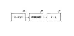
図3は、SHG素子24の温度を調節するためのブロック構成を示す。サーミスタ26は、温度の変化を抵抗値の変化として温度制御部27へ出力する。温度制御部27は、サーミスタ26により計測された温度とSHG素子24の設定温度との温度差からヒータ28へ供給する電力量を計算し、計算された電力量に応じた電力をヒータ28へ供給する。温度制御部27は、サーミスタ26による計測結果に基づいてヒータ28のフィードバック制御を行う。 FIG. 3 shows a block configuration for adjusting the temperature of the
ヒータ28は、温度制御部27により制御された電力に応じて熱を供給することで、サーミスタ26による計測結果に基づいてSHG素子24の温度を調節する。SHG素子24は、温度変化によって屈折率分布が変化する場合、位相整合条件が崩れ、波長を変換する効率が低下することが知られている。SHG素子24の温度変化を低減させることで、高い効率で安定した光量のレーザ光を供給することが可能となる。SHG素子24の温度調整にはヒータ28を用いる場合に限られず、他の構成、例えばペルチェ素子を用いることとしても良い。ペルチェ素子を用いる場合、熱を供給する他、熱を吸収することでSHG素子24の温度を調節することとしても良い。 The
図1に示すR光用光源装置11Rは、例えば、640nmの波長を持つレーザ光を供給する半導体レーザを有する。R光用光源装置11Rは、発光部である半導体レーザからのレーザ光を波長を変換させずに射出させる第1光源装置であって、第1色光であるR光を供給する。 The R
B光用光源装置11Bは、発光部である半導体レーザと、波長変換素子であるSHG素子とを有する。B光用光源装置11Bの半導体レーザは、例えば、930nmの波長を持つレーザ光を供給する。B光用光源装置11BのSHG素子は、例えば930nmのレーザ光を、465nmのレーザ光に変換させる。B光用光源装置11BのSHG素子は、図3に示す構成と同様の構成により温度調節がなされる。G光用光源装置11G、B光用光源装置11Bは、いずれも、波長変換素子で波長が変換されたレーザ光を射出させる第2光源装置であって、それぞれ第2色光であるG光、B光を供給する。なお、B光用光源装置11Bは、DPSSレーザ発振器であっても良い。 The
図4は、各色光用空間光変調装置14R、14G、14Bから射出される表示光を調整するためのブロック構成を示す。電源31は、プロジェクタ10の主電源である。マイクロコンピュータ等を備える制御部30は、各色光用光源装置11R、11G、11B、及び各色光用空間光変調装置14R、14G、14Bの駆動を制御する。R光用光源駆動部32Rは、制御部30による制御に応じてR光用光源装置11Rを駆動させる。G光用光源駆動部32Gは、制御部30による制御に応じてG光用光源装置11Gを駆動させる。B光用光源駆動部32Bは、制御部30による制御に応じてB光用光源装置11Bを駆動させる。R光用フォトダイオード(PD)33Rは、R光用光源装置11RからのR光の光量を計測する計測部である。G光用PD33Gは、G光用光源装置11GからのG光の光量を計測する計測部である。B光用PD33Bは、B光用光源装置11BからのB光の光量を計測する計測部である。 FIG. 4 shows a block configuration for adjusting display light emitted from the color light spatial
コンピュータ、DVDプレーヤ、TVチューナ等の外部機器からの画像信号は、制御部30の画像信号処理部(不図示)へ入力される。画像信号処理部は、画像信号の特性補正、増幅等により画像のリサイズ、ガンマ調整、色調整等を行う。また、画像信号処理部は、画像信号をR、G、Bの各映像データに分解する。制御部30の空間光変調信号生成部(不図示)は、画像信号処理部からの映像データに基づいて、各色光用空間光変調装置14R、14G、14Bを駆動するための空間光変調信号を生成する。R光用空間光変調駆動部34Rは、R光用の空間光変調信号に応じてR光用空間光変調装置14Rを駆動させる。G光用空間光変調駆動部34Gは、G光用の空間光変調信号に応じてG光用空間光変調装置14Gを駆動させる。B光用空間光変調駆動部34Bは、B光用の空間光変調信号に応じてB光用空間光変調装置14Bを駆動させる。 Image signals from external devices such as a computer, a DVD player, and a TV tuner are input to an image signal processing unit (not shown) of the
画像信号に応じた各色光の変調により適切な色バランスの画像を得るために、各色光が所定の光量比で供給される必要がある。SHG素子24(図3参照)の設定温度は、通常、環境温度より高い温度とされることから、ヒータ28の駆動を開始してからSHG素子24を設定温度にするまでには、少なくとも数秒の時間を要する。このため、G光用光源装置11G、B光用光源装置11Bは、電源31をONにしてから、所定の光量比を満たすレーザ光を射出させるまでに数秒の時間を要することになる。これに対して、R光用光源装置11Rは、SHG素子24を用いない直接発光を行うことから、数ナノ秒で所定の光量比を満たすレーザ光を射出させることができる。 In order to obtain an image with an appropriate color balance by modulating each color light according to the image signal, each color light needs to be supplied at a predetermined light quantity ratio. Since the set temperature of the SHG element 24 (see FIG. 3) is normally higher than the ambient temperature, it takes at least several seconds from the start of the
電源31をONにした瞬間から画像信号に応じた表示光を射出させる場合、G、Bに比べてRが強い、不適切な色バランスの画像が表示されることとなる。SHG素子24を設定温度にするまでの一定期間内であっても、不適切な色バランスの画像が表示されることは、観察者に不快感を与える等の不具合を引き起こす場合がある。 When the display light corresponding to the image signal is emitted from the moment when the
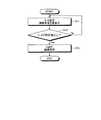
図5は、図4に示す構成により表示光を調整する制御工程について説明するフローチャートである。ステップS1では、電源31をONにすることで、各色光用光源装置11R、11G、11Bを点灯させる。また、電源31をONにすることで、G光用光源装置11G、B光用光源装置11Bに設けられたヒータ28(図3参照)の駆動を開始させる。さらに、制御部30は、画面全体を黒表示するための表示光の調整を行う。かかる黒表示は、画像信号以外の信号である起動時調整信号を用いた各色光用空間光変調装置14R、14G、14Bの制御により、全画面についてR、G、Bの各表示光を最低階調とすることで得られる。このように、制御部30は、全画面を同一の階調である最低階調とする調整を行う。ステップS1では、各色光用空間光変調装置14R、14G、14Bの制御により、各色光用空間光変調装置14R、14G、14Bから射出される表示光を調整する。 FIG. 5 is a flowchart illustrating a control process for adjusting display light by the configuration shown in FIG. In step S1, the
ステップS2では、G光用光源装置11GからのG光の光量、B光用光源装置11BからのB光の光量が基準値に到達したか否かが判断される。基準値は、適切な色バランスの画像を得ることが可能な光量比を満たす光量の値であって、色光ごとに設定される。制御部30は、G光用PD33G、及びB光用PD33Bによる計測結果に応じて、かかる判断を行う。制御部30は、G光用PD33G、及びB光用PD33Bによる計測結果に応じて、起動時調整信号による表示光の調整を行う。 In step S2, it is determined whether the amount of G light from the G
ステップS2においてG光、B光の光量が基準値に到達していないと判断された場合、ステップS1に戻って、各色光用光源装置11R、11G、11Bの点灯、及び黒表示が継続される。ステップS2においてG光、B光が基準値に到達したと判断された場合、ステップS3において、画像表示を開始させる。ステップS3は、互いに異なる色光を供給する光供給工程、及び色光を画像信号に応じて変調する変調工程である。画像表示は、起動時調整信号を用いた調整から、通常の画像信号に応じた各色光用空間光変調装置14R、14G、14Bの駆動への切り換えにより開始される。 If it is determined in step S2 that the amounts of G light and B light have not reached the reference values, the process returns to step S1, and the lighting of each color
図6は、各色光用光源装置11R、11G、11Bからの各色光の光量と時間との関係、及び起動時調整信号、画像信号の出力期間を説明するものである。なお、ここでは各色光について同一の値Lを基準値としているが、基準値Lの絶対量は、色光ごとに異なるものとする。電源31をONにした時間t0の直後に、R光用光源装置11RからのR光の光量は、基準値Lに到達する。これに対して、G光用光源装置11GからのG光の光量、B光用光源装置11BからのB光の光量は、時間t0から時間が経過するに従って増加し、時間t1において基準値Lに到達する。このように、第1色光であるR光の光量が基準値Lとなった後に、第2色光であるG光、B光の光量が基準値となる。 FIG. 6 illustrates the relationship between the amount of light of each color light from each color
制御部30は、時間t0から時間t1までの期間において、画像信号の出力を停止させ、起動時調整信号を出力する。制御部30は、G光用光源装置11GからのG光、B光用光源装置11BからのB光の光量がいずれも基準値Lとなるまでの間において、全画面を最低階調とする調節を行う。このように、制御部30は、各色光用光源装置11R、11G、11Bへの電力供給が開始されてから各色光の光量が基準値Lとなるまでの間において、起動時調整信号を用いて表示光を調整する。 The
さらに、制御部30は、時間t1において起動時調整信号の出力を停止するとともに、画像信号の出力を開始する。制御部30は、G光、B光の光量がいずれも基準値Lに到達した以降において、画像信号に応じた画像を表示させる。計測部であるG光用PD33G、B光用PD33Bによる計測結果に基づいて表示光を調整することで、起動時調整信号を用いた調整から、通常の画像信号に応じた駆動への切り換えを正確なタイミングで行うことができる。なお、各色光用PD33R、33G、33Bは、画像を表示する間は、各色光用光源装置11R、11G、11Bのフィードバック制御に用いることができる。 Further, the
各色光の光量が基準値Lとなるまでの間は、画像信号に応じた変調をしたとしても不適切な色バランスで表示されることとなる。光量が基準値Lとなるまでの間、起動時調整信号を用いて表示光を調整することで、不適切な色バランスの画像を表示させなくすることが可能になる。これにより、色光ごとの複数の光源装置を用いる構成において、常時適切な色バランスの画像を表示することができるという効果を奏する。本発明は、波長変換素子を用いない第1光源装置からのレーザ光と、波長変換素子を用いる第2光源装置からのレーザ光とを用いて画像を表示する場合に適している。 Until the light quantity of each color light reaches the reference value L, even if modulation according to the image signal is performed, the display is performed with an inappropriate color balance. By adjusting the display light using the startup adjustment signal until the light amount reaches the reference value L, it is possible to prevent an image with an inappropriate color balance from being displayed. Thereby, in the structure using the several light source device for every color light, there exists an effect that the image of an appropriate color balance can always be displayed. The present invention is suitable for displaying an image using laser light from a first light source device that does not use a wavelength conversion element and laser light from a second light source device that uses a wavelength conversion element.
図7は、起動時調整信号、画像信号の出力期間の他の態様について説明するものである。所定値L’は、目視により確認される画像の色バランスに違和感が無い程度の光量であって、基準値Lの例えば80%に相当する値である。G光用光源装置11GからのG光の光量、B光用光源装置11BからのB光の光量は、時間t1以前の時間t1’において所定値L’に到達する。 FIG. 7 is a diagram for explaining another aspect of the output period of the startup adjustment signal and the image signal. The predetermined value L ′ is a light amount that does not cause a sense of incongruity in the color balance of the image visually confirmed, and is a value corresponding to, for example, 80% of the reference value L. The amount of G light from the G
制御部30は、時間t0から時間t1’までの期間において、画像信号の出力を停止させ、起動時調整信号を出力する。制御部30は、G光用光源装置11GからのG光、B光用光源装置11BからのB光の光量が、いずれも所定値L’となるまでの間において、全画面を最低階調とする調節を行う。さらに、制御部30は、時間t1’において起動時調整信号の出力を停止するとともに、画像信号の出力を開始する。このように、制御部30は、G光、B光の光量がいずれも基準値Lに到達する以前に、画像信号に応じた画像表示を開始させる。これにより、各色光用光源装置11R、11G、11Bへの電力供給から早い時期に、違和感の無い色バランスの画像を表示できる。なお、画像表示を開始させるときのG光、B光の光量の所定値L’は、基準値Lの80%相当である場合に限られず、適宜設定することができる。目視により確認される画像の色バランスに違和感が無ければ良い。 The
本実施例において、制御部30は、計測部である各色光用PD33R、33G、33Bによる計測結果に応じて、起動時調整信号による表示光の調整を行う場合に限られない。例えば、電源をONにしてから光量が基準値Lに到達するまでの期間を予め求めておき、かかる期間が経過するまでの間、起動時調整信号による表示光の調整を行うこととしても良い。また、サーミスタ26(図3参照)による計測結果に応じて表示光の調整を行うこととしても良い。この場合、SHG素子24が設定温度に到達するまでの間、起動時調整信号により表示光を調整することができる。 In the present embodiment, the
各色光用光源装置11R、11G、11Bは、半導体レーザを用いる構成に限られない。固体レーザ、液体レーザ、ガスレーザ等を用いる構成であっても良い。また、各色光用光源装置11R、11G、11Bは、レーザ光源以外の他の光源であって、色光ごとの光源を適用可能なもの、例えばLEDや有機EL等を用いる構成であっても良い。 Each color
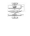
図8は、本実施例の変形例1について説明するフローチャートである。本変形例は、起動時調整信号を用いて空間光変調装置及び光源装置を制御することにより表示光を調整することを特徴とする。ステップS11では、G光用光源装置11G及びB光用光源装置11Bのみを点灯させる。制御部30は、起動時調整信号を用いた制御により、G光用光源装置11G及びB光用光源装置11Bのみを点灯させる。また、起動時調整信号を用いたG光用空間光変調装置14G、B光用空間光変調装置14Bの制御により、画面全体を黒表示するための表示光の調整を行う。 FIG. 8 is a flowchart for explaining the first modification of the present embodiment. The present modification is characterized in that the display light is adjusted by controlling the spatial light modulation device and the light source device using the startup adjustment signal. In step S11, only the G
ステップS12では、G光用光源装置11GからのG光の光量、B光用光源装置11BからのB光の光量が上述の所定値に到達したか否かが判断される。ステップS12においてG光、B光が基準値に到達していないと判断された場合、ステップS11に戻って、G光用光源装置11G、B光用光源装置11Bの点灯、及び黒表示が継続される。ステップS12においてG光、B光の光量が基準値に到達したと判断された場合、ステップS13において、R光用光源装置11Rを点灯させるとともに、画像表示を開始させる。R光用光源装置11Rの点灯及び画像表示は、起動時調整信号を用いた調整から、通常の画像信号に応じた各色光用光源装置11R、11G、11B、各色光用空間光変調装置14R、14G、14Bの駆動への切り換えにより開始される。 In step S12, it is determined whether the amount of G light from the G
図9は、各色光用光源装置11R、11G、11Bからの各色光の光量と時間との関係、及び起動時調整信号、画像信号の出力期間を説明するものである。G光用光源装置11GからのG光の光量、B光用光源装置11BからのB光の光量は、時間t1’において所定値L’、時間t1において基準値Lにそれぞれ到達する。時間t0〜t1’において、制御部30は、起動時調整信号によりG光用光源装置11G、B光用光源装置11Bのみを点灯させるとともに、黒表示を行う。 FIG. 9 illustrates the relationship between the amount of light of each color light from each color
時間t1’において、制御部30は、画像信号によりR光用光源装置11Rの駆動、及び通常の画像の表示を開始させる。時間t1’の直後に、R光用光源装置11RからのR光の光量は、基準値Lに到達する。本変形例においても、常時適切な色バランスの画像を表示することができる。また、時間t0〜t1’の期間においてR光用光源装置11Rの駆動を停止させることで、消費電力を低減させることができる。なお、本変形例の場合も、G光、B光の光量が基準値Lに到達した時間t1において起動時調整信号を画像信号に切り換えることとしても良い。 At time t <b> 1 ′, the
図10は、本実施例の変形例2について説明するフローチャートである。本変形例は、起動時調整信号を用いて光源装置を制御することにより表示光を調整することを特徴とする。ステップS21では、各色光用光源装置11R、11G、11Bを点灯させる。また、制御部30は、起動時調整信号により、第2色光であるG光、B光の光量に応じて第1色光であるR光の光量を調整する。G光、B光の光量に応じたR光の光量の調整は、各色光用PD33R、33G、33Bによる計測結果に基づいてR光用光源装置11Rを制御することにより行うことができる。さらに、制御部30は、画像信号に応じた画像を表示させる。 FIG. 10 is a flowchart for explaining a second modification of the present embodiment. This modification is characterized in that the display light is adjusted by controlling the light source device using the startup adjustment signal. In step S21, each color
ステップS22では、G光用光源装置11GからのG光の光量、B光用光源装置11BからのB光の光量が基準値に到達したか否かが判断される。ステップS22においてG光、B光の光量が基準値に到達していないと判断された場合、ステップS21に戻って、各色光用光源装置11R、11G、11Bの点灯、R光の光量の調整及び画像表示が継続される。ステップS22においてG光、B光が基準値に到達したと判断された場合、ステップS23において、R光の光量の調整が停止される。R光の光量の調整の停止は、起動時調整信号の出力を停止させることにより行う。 In step S22, it is determined whether the amount of G light from the G
図11は、各色光用光源装置11R、11G、11Bからの各色光の光量と時間との関係、及び起動時調整信号、画像信号の出力期間を説明するものである。R光用光源装置11RからのR光の光量は、G光、B光と同様に、時間t0から時間が経過するに従って増加し、時間t1において基準値Lに到達する。制御部30は、時間t0において画像信号の出力を開始させる。また、制御部30は、時間t0〜t1の期間において、起動時調整信号によりR光用光源装置11RからのR光の光量を調整する。このように、制御部30は、第2色光であるG光、B光の光量が基準値Lとなるまでの間、G光、B光の光量に応じて第1色光であるR光の光量を調整する。R光の光量の調整により、時間t0〜t1の期間における画像は、時間t1以降の画像と比較すると低い輝度であるものの、適切な色バランスで表示される。 FIG. 11 illustrates the relationship between the amount of light of each color light from each color
R光の光量を調整することで、時間t0〜t1においても、適切な色バランスの画像を表示することができる。これにより、本変形例においても、常時適切な色バランスの画像を表示することができる。また、電源31をONにした直後から、適切な色バランスの画像を表示することができる。 By adjusting the amount of R light, an image with an appropriate color balance can be displayed even at times t0 to t1. Thereby, also in this modification, the image of a suitable color balance can always be displayed. Also, an image with an appropriate color balance can be displayed immediately after the
本発明の画像表示装置であるプロジェクタ10は、空間光変調装置として透過型液晶表示装置を用いる場合に限られない。空間光変調装置としては、反射型液晶表示装置(Liquid Crystal On Silicon;LCOS)、DMD(Digital Micromirror Device)、GLV(Grating Light Valve)等を用いても良い。プロジェクタ10は、色光ごとに空間光変調装置を備える構成に限られない。プロジェクタ10は、一の空間光変調装置により2つ又は3つ以上の色光を変調する構成としても良い。 The
プロジェクタ10は、R、G、Bの3つの光源装置11R、11G、11Bを用いる構成に限られない。プロジェクタ10は、4つ以上の光源装置を用いる構成であっても良い。さらに、本発明の画像表示装置は、スクリーンの一方の面に光を供給し、スクリーンの他方の面から射出される光を観察することで画像を鑑賞する、いわゆるリアプロジェクタであっても良い。 The
以上のように、本発明に係る光源装置は、プロジェクタに用いる場合に適している。 As described above, the light source device according to the present invention is suitable for use in a projector.
10 プロジェクタ、11R R光用光源装置、11G G光用光源装置、11B B光用光源装置、12 拡散素子、13 フィールドレンズ、14R R光用空間光変調装置、14G G光用空間光変調装置、14B B光用空間光変調装置、15 クロスダイクロイックプリズム、16 第1ダイクロイック膜、17 第2ダイクロイック膜、18 投写レンズ、19 スクリーン、21 励起用レーザ、22 第1共振ミラー、23 レーザ結晶、24 SHG素子、25 第2共振ミラー、26 サーミスタ、27 温度制御部、28 ヒータ、30 制御部、31 電源、32R R光用光源駆動部、32G G光用光源駆動部、32B B光用光源駆動部、33R R光用PD、33G G光用PD、33B B光用PD、34R R光用空間光変調駆動部、34G G光用空間光変調駆動部、34B B光用空間光変調駆動部 DESCRIPTION OF
Claims (2)
Translated fromJapanese前記光源装置からの前記色光を画像信号に応じて変調する空間光変調装置と、
前記光源装置及び前記空間光変調装置の少なくとも一方を制御することにより、前記空間光変調装置から射出される表示光を調整する制御部と、を有し、
前記制御部は、前記光源装置への電力供給が開始されてから各色光の光量が前記色光ごとに設定された基準値となるまでの間に、前記画像信号以外の信号である起動時調整信号を用いて前記表示光を調整するものであり、
複数の前記光源装置は、第1色光を供給する第1光源装置と、前記第1色光とは異なる第2色光を供給する第2光源装置と、を備え、
前記第1光源装置は、光を発生させるレーザ発光部を備え、前記レーザ発光部からの光を波長を変換させずに射出させるものであり、
前記第2光源装置は、光を発生させるレーザ発光部と、前記レーザ発光部からの光の波長を変換させる波長変換素子と、を備え、前記波長変換素子で波長が変換された光を射出させるものであり、
前記第1光源装置からの前記第1色光の光量が前記基準値となった後に、前記第2光源装置からの前記第2色光の光量が前記基準値となる場合において、
前記制御部は、前記第2光源装置からの前記第2色光の光量が前記基準値となるまでの間に、前記第2光源装置からの前記第2色光の光量に応じて前記第1光源装置からの前記第1色光の光量を調整し、前記画像信号に応じた画像を表示させることを特徴とする画像表示装置。A plurality of light source devices for supplying different color lights;
A spatial light modulator that modulates the color light from the light source device according to an image signal;
A control unit that adjusts display light emitted from the spatial light modulation device by controlling at least one of the light source device and the spatial light modulation device, and
The control unit is a start-up adjustment signal that is a signal other than the image signal from when power supply to the light source device is started until the light amount of each color light reaches a reference value set for each color light.It is intended to adjust the display light usinga
The plurality of light source devices include a first light source device that supplies first color light, and a second light source device that supplies second color light different from the first color light,
The first light source device includes a laser light emitting unit that generates light, and emits light from the laser light emitting unit without converting the wavelength,
The second light source device includes a laser light emitting unit that generates light and a wavelength conversion element that converts a wavelength of light from the laser light emitting unit, and emits light whose wavelength is converted by the wavelength conversion element. Is,
In the case where the light amount of the second color light from the second light source device becomes the reference value after the light amount of the first color light from the first light source device becomes the reference value,
The first light source device according to the light amount of the second color light from the second light source device until the light amount of the second color light from the second light source device reaches the reference value. An image display devicethat adjusts the light amount of the first color light from and displays an image according to the image signal .
互いに異なる色光を供給する光供給工程と、
前記色光を画像信号に応じて変調する変調工程と、
前記光源装置及び前記空間光変調装置の少なくとも一方を制御することにより、前記空間光変調装置から射出される表示光を調整する制御工程と、を含み、
前記制御工程において、前記光源装置への電力供給が開始されてから各色光の光量が前
記色光ごとに設定された基準値となるまでの間に、前記画像信号以外の信号である起動時
調整信号を用いて前記表示光を調整するものであり、
複数の前記光源装置は、第1色光を供給する第1光源装置と、前記第1色光とは異なる
第2色光を供給する第2光源装置と、を備え、
前記第1光源装置は、光を発生させるレーザ発光部を備え、前記レーザ発光部からの光を波長を変換させずに射出させるものであり、
前記第2光源装置は、光を発生させるレーザ発光部と、前記レーザ発光部からの光の波長を変換させる波長変換素子と、を備え、前記波長変換素子で波長が変換された光を射出させるものであり、
前記第1光源装置からの前記第1色光の光量が前記基準値となった後に、前記第2光源装置からの前記第2色光の光量が前記基準値となる場合において、
前記制御工程において、前記第2光源装置からの前記第2色光の光量が前記基準値となるまでの間に、前記第2光源装置からの前記第2色光の光量に応じて前記第1光源装置からの前記第1色光の光量を調整し、前記画像信号に応じた画像を表示させることを特徴とする画像表示装置の制御方法。A control method for an image display device, comprising: a plurality of light source devices that supply different color lights; and a spatial light modulation device that modulates the color light from the light source device according to an image signal,
A light supply process for supplying different color lights;
A modulation step of modulating the color light according to an image signal;
A control step of adjusting display light emitted from the spatial light modulation device by controlling at least one of the light source device and the spatial light modulation device,
In the control step, a start-up adjustment signal that is a signal other than the image signal from when the power supply to the light source device is started until the light amount of each color light reaches a reference value set for each color lightIt is intended to adjust the display light usinga
The plurality of light source devices are different from the first light source device that supplies first color light and the first color light.
A second light source device for supplying a second color light,
The first light source device includes a laser light emitting unit that generates light, and emits light from the laser light emitting unit without converting the wavelength,
The second light source device includes a laser light emitting unit that generates light and a wavelength conversion element that converts a wavelength of light from the laser light emitting unit, and emits light whose wavelength is converted by the wavelength conversion element. Is,
In the case where the light amount of the second color light from the second light source device becomes the reference value after the light amount of the first color light from the first light source device becomes the reference value,
In the control step, the first light source device according to the light amount of the second color light from the second light source device until the light amount of the second color light from the second light source device reaches the reference value. A method for controlling an image display device, comprising: adjusting an amount of light of the first color light from an image to display an image according to the image signal .
Priority Applications (2)
| Application Number | Priority Date | Filing Date | Title |
|---|---|---|---|
| JP2007033118AJP4325683B2 (en) | 2007-02-14 | 2007-02-14 | Image display device and method for controlling image display device |
| US12/069,202US7686456B2 (en) | 2007-02-14 | 2008-02-09 | Image display apparatus and method |
Applications Claiming Priority (1)
| Application Number | Priority Date | Filing Date | Title |
|---|---|---|---|
| JP2007033118AJP4325683B2 (en) | 2007-02-14 | 2007-02-14 | Image display device and method for controlling image display device |
Publications (2)
| Publication Number | Publication Date |
|---|---|
| JP2008197422A JP2008197422A (en) | 2008-08-28 |
| JP4325683B2true JP4325683B2 (en) | 2009-09-02 |
Family
ID=39685264
Family Applications (1)
| Application Number | Title | Priority Date | Filing Date |
|---|---|---|---|
| JP2007033118AExpired - Fee RelatedJP4325683B2 (en) | 2007-02-14 | 2007-02-14 | Image display device and method for controlling image display device |
Country Status (2)
| Country | Link |
|---|---|
| US (1) | US7686456B2 (en) |
| JP (1) | JP4325683B2 (en) |
Families Citing this family (7)
| Publication number | Priority date | Publication date | Assignee | Title |
|---|---|---|---|---|
| JP4348457B2 (en) | 2002-03-13 | 2009-10-21 | ドルビー ラボラトリーズ ライセンシング コーポレイション | High dynamic range display, display controller, and image display method |
| JP5616569B2 (en)* | 2004-04-15 | 2014-10-29 | オニキス セラピューティクス, インク.Onyx Therapeutics, Inc. | Compounds for enzyme inhibition |
| EP2030981B1 (en)* | 2004-05-10 | 2014-07-09 | Onyx Therapeutics, Inc. | Compounds for proteasome enzyme inhibition |
| MY171061A (en)* | 2005-11-09 | 2019-09-24 | Onyx Therapeutics Inc | Compounds for enzyme inhibition |
| AU2007261345B2 (en)* | 2006-06-19 | 2012-02-23 | Onyx Therapeutics, Inc. | Peptide epoxyketones for proteasome inhibition |
| JP5851615B2 (en)* | 2011-09-14 | 2016-02-03 | インテル・コーポレーション | Holographic display system, method and device |
| JP2017021938A (en)* | 2015-07-08 | 2017-01-26 | パナソニックIpマネジメント株式会社 | Dimming control unit, lighting system, and equipment |
Family Cites Families (12)
| Publication number | Priority date | Publication date | Assignee | Title |
|---|---|---|---|---|
| JP4792665B2 (en)* | 2001-06-18 | 2011-10-12 | ソニー株式会社 | Light source control device and method, and projection display device |
| JP4348457B2 (en)* | 2002-03-13 | 2009-10-21 | ドルビー ラボラトリーズ ライセンシング コーポレイション | High dynamic range display, display controller, and image display method |
| JP2004004284A (en)* | 2002-05-31 | 2004-01-08 | Canon Inc | Projection display device |
| US6817717B2 (en)* | 2002-09-19 | 2004-11-16 | Hewlett-Packard Development Company, L.P. | Display system with low and high resolution modulators |
| EP1640799B1 (en) | 2003-06-06 | 2012-11-14 | Panasonic Corporation | Laser projector with indoor illumination |
| US7357513B2 (en)* | 2004-07-30 | 2008-04-15 | Novalux, Inc. | System and method for driving semiconductor laser sources for displays |
| US7322704B2 (en)* | 2004-07-30 | 2008-01-29 | Novalux, Inc. | Frequency stabilized vertical extended cavity surface emitting lasers |
| US20060023757A1 (en)* | 2004-07-30 | 2006-02-02 | Aram Mooradian | Apparatus, system, and method for wavelength conversion of mode-locked extended cavity surface emitting semiconductor lasers |
| WO2006015133A2 (en)* | 2004-07-30 | 2006-02-09 | Novalux, Inc. | Projection display apparatus, system, and method |
| WO2006105258A2 (en)* | 2005-03-30 | 2006-10-05 | Novalux, Inc. | Manufacturable vertical extended cavity surface emitting laser arrays |
| JP4619310B2 (en)* | 2005-06-23 | 2011-01-26 | 三洋電機株式会社 | Projection-type image display device |
| US20070013871A1 (en)* | 2005-07-15 | 2007-01-18 | Marshall Stephen W | Light-emitting diode (LED) illumination in display systems using spatial light modulators (SLM) |
- 2007
- 2007-02-14JPJP2007033118Apatent/JP4325683B2/ennot_activeExpired - Fee Related
- 2008
- 2008-02-09USUS12/069,202patent/US7686456B2/ennot_activeExpired - Fee Related
Also Published As
| Publication number | Publication date |
|---|---|
| US7686456B2 (en) | 2010-03-30 |
| US20080191641A1 (en) | 2008-08-14 |
| JP2008197422A (en) | 2008-08-28 |
Similar Documents
| Publication | Publication Date | Title |
|---|---|---|
| JP4341685B2 (en) | Light source device and projector | |
| JP4325683B2 (en) | Image display device and method for controlling image display device | |
| JP5799756B2 (en) | projector | |
| JP4924677B2 (en) | Light source device, projection device, and projection method | |
| JP4240122B2 (en) | LIGHT SOURCE DEVICE AND ITS CONTROL METHOD, LIGHTING DEVICE, MONITOR DEVICE, AND IMAGE DISPLAY DEVICE | |
| US7354157B2 (en) | Image display device and light source device | |
| JP4416018B2 (en) | Wavelength conversion element, light source device, illumination device, monitor device, and projector | |
| JP4085666B2 (en) | Image display device | |
| JP6417709B2 (en) | Projector and projector control method | |
| JP2009134217A (en) | projector | |
| US9286860B2 (en) | Image display device | |
| JPWO2018083895A1 (en) | Projection type display device and control method of projection type display device | |
| JP7098483B2 (en) | Light source device and image projection device | |
| JP2008140820A (en) | Laser light source device driving method, laser light source device, image display device, monitor device, and illumination device | |
| JP2009038182A (en) | Light source device, illumination device, projector and monitor device | |
| JP2008198824A (en) | Light source device, illumination device, monitor device, and image display device | |
| WO2018205420A1 (en) | Exciting light intensity control system and method, and projection system | |
| JP4858182B2 (en) | LIGHT SOURCE DEVICE, PROJECTOR, AND LIGHT SOURCE DEVICE CONTROL METHOD | |
| JP2008153332A (en) | Light source device and projector | |
| JP2012242708A (en) | Image forming apparatus | |
| JP4894675B2 (en) | LIGHT SOURCE DEVICE, LIGHTING DEVICE, MONITOR DEVICE, IMAGE DISPLAY DEVICE, AND LIGHT SOURCE DEVICE CONTROL METHOD | |
| JP2008164900A (en) | LIGHT SOURCE DEVICE, LIGHTING DEVICE, MONITOR DEVICE, PROJECTOR, AND LIGHT SOURCE DEVICE CONTROL METHOD | |
| JP2008286823A (en) | Light source device, lighting device, and projector | |
| JP2018124389A (en) | Projector and method for controlling projector | |
| JP6070793B2 (en) | Projector control method and projector |
Legal Events
| Date | Code | Title | Description |
|---|---|---|---|
| A977 | Report on retrieval | Free format text:JAPANESE INTERMEDIATE CODE: A971007 Effective date:20090105 | |
| A131 | Notification of reasons for refusal | Free format text:JAPANESE INTERMEDIATE CODE: A131 Effective date:20090224 | |
| A521 | Request for written amendment filed | Free format text:JAPANESE INTERMEDIATE CODE: A523 Effective date:20090417 | |
| TRDD | Decision of grant or rejection written | ||
| A01 | Written decision to grant a patent or to grant a registration (utility model) | Free format text:JAPANESE INTERMEDIATE CODE: A01 Effective date:20090519 | |
| A01 | Written decision to grant a patent or to grant a registration (utility model) | Free format text:JAPANESE INTERMEDIATE CODE: A01 | |
| A61 | First payment of annual fees (during grant procedure) | Free format text:JAPANESE INTERMEDIATE CODE: A61 Effective date:20090601 | |
| FPAY | Renewal fee payment (event date is renewal date of database) | Free format text:PAYMENT UNTIL: 20120619 Year of fee payment:3 | |
| R150 | Certificate of patent or registration of utility model | Ref document number:4325683 Country of ref document:JP Free format text:JAPANESE INTERMEDIATE CODE: R150 Free format text:JAPANESE INTERMEDIATE CODE: R150 | |
| FPAY | Renewal fee payment (event date is renewal date of database) | Free format text:PAYMENT UNTIL: 20130619 Year of fee payment:4 | |
| FPAY | Renewal fee payment (event date is renewal date of database) | Free format text:PAYMENT UNTIL: 20130619 Year of fee payment:4 | |
| S531 | Written request for registration of change of domicile | Free format text:JAPANESE INTERMEDIATE CODE: R313531 | |
| R350 | Written notification of registration of transfer | Free format text:JAPANESE INTERMEDIATE CODE: R350 | |
| LAPS | Cancellation because of no payment of annual fees |