JP4325524B2 - Switch device and system, backup and restore method and program - Google Patents
Switch device and system, backup and restore method and programDownload PDFInfo
- Publication number
- JP4325524B2 JP4325524B2JP2004284378AJP2004284378AJP4325524B2JP 4325524 B2JP4325524 B2JP 4325524B2JP 2004284378 AJP2004284378 AJP 2004284378AJP 2004284378 AJP2004284378 AJP 2004284378AJP 4325524 B2JP4325524 B2JP 4325524B2
- Authority
- JP
- Japan
- Prior art keywords
- file
- backup
- snapshot
- file system
- server
- Prior art date
- Legal status (The legal status is an assumption and is not a legal conclusion. Google has not performed a legal analysis and makes no representation as to the accuracy of the status listed.)
- Expired - Fee Related
Links
Images


Classifications
- G—PHYSICS
- G06—COMPUTING OR CALCULATING; COUNTING
- G06F—ELECTRIC DIGITAL DATA PROCESSING
- G06F11/00—Error detection; Error correction; Monitoring
- G06F11/07—Responding to the occurrence of a fault, e.g. fault tolerance
- G06F11/14—Error detection or correction of the data by redundancy in operation
- G06F11/1402—Saving, restoring, recovering or retrying
- G06F11/1446—Point-in-time backing up or restoration of persistent data
- G06F11/1458—Management of the backup or restore process
- G06F11/1469—Backup restoration techniques
- G—PHYSICS
- G06—COMPUTING OR CALCULATING; COUNTING
- G06F—ELECTRIC DIGITAL DATA PROCESSING
- G06F11/00—Error detection; Error correction; Monitoring
- G06F11/07—Responding to the occurrence of a fault, e.g. fault tolerance
- G06F11/14—Error detection or correction of the data by redundancy in operation
- G06F11/1402—Saving, restoring, recovering or retrying
- G06F11/1446—Point-in-time backing up or restoration of persistent data
- G06F11/1456—Hardware arrangements for backup
- G—PHYSICS
- G06—COMPUTING OR CALCULATING; COUNTING
- G06F—ELECTRIC DIGITAL DATA PROCESSING
- G06F16/00—Information retrieval; Database structures therefor; File system structures therefor
- G06F16/10—File systems; File servers
- G06F16/11—File system administration, e.g. details of archiving or snapshots
- G06F16/128—Details of file system snapshots on the file-level, e.g. snapshot creation, administration, deletion
- G—PHYSICS
- G06—COMPUTING OR CALCULATING; COUNTING
- G06F—ELECTRIC DIGITAL DATA PROCESSING
- G06F16/00—Information retrieval; Database structures therefor; File system structures therefor
- G06F16/10—File systems; File servers
- G06F16/18—File system types
- G06F16/182—Distributed file systems
- G06F16/1824—Distributed file systems implemented using Network-attached Storage [NAS] architecture
- G06F16/1827—Management specifically adapted to NAS
- G—PHYSICS
- G06—COMPUTING OR CALCULATING; COUNTING
- G06F—ELECTRIC DIGITAL DATA PROCESSING
- G06F16/00—Information retrieval; Database structures therefor; File system structures therefor
- G06F16/10—File systems; File servers
- G06F16/18—File system types
- G06F16/188—Virtual file systems
- G06F16/192—Implementing virtual folder structures
- G—PHYSICS
- G06—COMPUTING OR CALCULATING; COUNTING
- G06F—ELECTRIC DIGITAL DATA PROCESSING
- G06F11/00—Error detection; Error correction; Monitoring
- G06F11/07—Responding to the occurrence of a fault, e.g. fault tolerance
- G06F11/14—Error detection or correction of the data by redundancy in operation
- G06F11/1402—Saving, restoring, recovering or retrying
- G06F11/1446—Point-in-time backing up or restoration of persistent data
- G06F11/1458—Management of the backup or restore process
- G06F11/1466—Management of the backup or restore process to make the backup process non-disruptive
Landscapes
- Engineering & Computer Science (AREA)
- Theoretical Computer Science (AREA)
- Physics & Mathematics (AREA)
- General Engineering & Computer Science (AREA)
- General Physics & Mathematics (AREA)
- Data Mining & Analysis (AREA)
- Databases & Information Systems (AREA)
- Quality & Reliability (AREA)
- Information Retrieval, Db Structures And Fs Structures Therefor (AREA)
Description
Translated fromJapanese本発明は、クライアントとファイルサーバとの間に論理的に配置されるスイッチ装置に関し、特に、クライアントからみて複数のファイルシステムを仮想化した1つのファイルシステムとしてファイルアクセスサービスを提供するシステムにおいて、スナップショット、バックアップ/リストア操作を効率的に行うスイッチ装置及び方法並びにコンピュータプログラムに関する。 The present invention relates to a switch device that is logically arranged between a client and a file server. In particular, in a system that provides a file access service as a single file system obtained by virtualizing a plurality of file systems as seen from the client, The present invention relates to a switch device and method for efficiently performing shot and backup / restore operations, and a computer program.
プロトコルとしてNFS(NFS;Network File System)/CIFS(Common Internet File System)を用い、複数のホストからファイルシステムへのアクセスを可能としたネットワークストレージシステムとして、例えばNAS(Network Attached Storage;ネットワークアタチッドストレージ)等が用いられている。ここで、NASは、NFS、CIFS等を介してファイルを共有するコンピュータ、又はデバイスをいう。 For example, NAS (Network Attached Storage) is a network storage system that uses NFS (NFS: Network File System) / CIFS (Common Internet File System) as a protocol and enables access from multiple hosts to the file system. Storage) or the like. Here, NAS refers to a computer or device that shares files via NFS, CIFS, or the like.
ストレージに記録されたデータは、障害発生時等にデータを復元できるように、例えば定期的にテープ等の媒体にバックアップされる。このうち、スナップショットは、ある時点でのファイルシステム構造のイメージを保持した読み取り専用のファイルシステムである。スナップショットをとることで、その後、当該スナップショット作成時点でのファイルシステム構造の固定化されたイメージにアクセスすることができ、また当該スナップショット作成時点のデータに復元することができる(論理ボリュームの復元ができる)。このため、スナップショットは、一例として、スナップされたファイルシステムの一貫したバックアップをとる目的で使用される。なお、スナップショットについては、例えば後記特許文献1、非特許文献1等が参照される。後述されるように、本発明では、複数のスナップショットを繋ぐ処理が行われる。以下では、技術の理解に供するため、まず、スナップショットについて、その概略を、後記特許文献1等の記載に基づき説明しておく。なお、特許文献1には、複数のスナップショットが与えられたときにそれを管理する方法として、ファイルシステム内に、そのファイルシステムを表す一連のメタデータを含め、ファイルシステムのスナップショットがそれに関連するメタデータを含むようにした方法が開示されている。 The data recorded in the storage is backed up on a medium such as a tape periodically so that the data can be restored when a failure occurs. Among these, the snapshot is a read-only file system that holds an image of the file system structure at a certain point in time. By taking a snapshot, you can then access an image with a fixed file system structure at the time of the snapshot creation, and restore the data at the time of the snapshot creation (the logical volume Can be restored). For this reason, snapshots are used as an example for the purpose of taking a consistent backup of a snapped file system. For snapshots, refer to, for example,
ある時点でのファイルシステム構造のイメージが、例えば図13(A)に示すようなファイルシステムをスナップすると、図13(B)のようなスナップショットinodeが作成される。なお、inodeは、ファイルシステム層が、ファイルを記述するためのデータ構造体である。スナップショットinodeは、ファイルシステム構造のルートinodeの複製であり、図13(A)と同じく、inode間接ブロック、inodeファイルデータブロック、ファイルデータブロックA〜Cのポインタ情報を有する。このように、スナップショットの作成は、ポインタ情報を取得するだけであることから、大規模データについても、その作成に要する時間は、例えば数秒程度とされる。そして、スナップショット作成後、例えばファイルデータブロックCが変更された場合、図13(C)に示すように、変更されたファイルデータブロックを指すinodeファイルデータブロックは、変更されたファイルデータブロックの新たな位置C’を反映するように変更される(WAFL(Write Anywhere File Layout)の場合)。スナップショットinodeは元のinodeファイルシステム間接ブロックを指すポインタを含み、inodeファイルデータブロックは元のファイルデータブロックA、B、Cへのポインタを保持している。すなわち、スナップショットは、スナップ時点でのファイルシステムの固定化イメージを保持する。一方、新たに書き込まれたinodeファイルデータブロックは、ファイルデータブロックA、Bへのポインタと、変更されたファイルデータブロックC’へのポインタ情報を保持する。あるいは、スナップされたファイルシステムにその後、変更が加えられると、変更前のデータ(例えば図13(C)のファイルデータブロックC)が、スナップショット領域に、コピーされ、スナップショットの読み取り時、変更された元のデータ(例えば図13(C)のファイルデータブロックC)は、スナップショットから読み取られる構成とされるものもある(例えば非特許文献1参照)。 When an image of the file system structure at a certain point in time snaps a file system as shown in FIG. 13A, for example, a snapshot inode as shown in FIG. 13B is created. Note that inode is a data structure for the file system layer to describe a file. The snapshot inode is a copy of the root inode of the file system structure, and has pointer information of the inode indirect block, the inode file data block, and the file data blocks A to C, as in FIG. As described above, since the creation of the snapshot only involves obtaining the pointer information, the time required for the creation of the large-scale data is, for example, about several seconds. When the file data block C is changed after the snapshot is created, for example, as shown in FIG. 13C, the inode file data block indicating the changed file data block is a new one of the changed file data block. To reflect the correct position C ′ (in the case of WAFL (Write Anywhere File Layout)). The snapshot inode includes a pointer that points to the original inode file system indirect block, and the inode file data block holds pointers to the original file data blocks A, B, and C. That is, the snapshot holds a fixed image of the file system at the time of snapping. On the other hand, the newly written inode file data block holds pointers to the file data blocks A and B and pointer information to the changed file data block C ′. Alternatively, when a change is subsequently made to the snapped file system, the data before the change (for example, the file data block C in FIG. 13C) is copied to the snapshot area and changed when the snapshot is read. In some cases, the original data (for example, the file data block C in FIG. 13C) is read from a snapshot (see, for example, Non-Patent Document 1).
スナップショット作成後にファイルが変更された場合、スナップショットinodeにアクセスすることにより、ファイルシステムのinode構造をスナップショット作成時点のものに復元することができる。より詳細には、ファイルシステムは、スナップショットinodeに保持されるポインタをたどりinodeファイル間接ブロック及びinodeファイルデータブロックを通して、未変更のファイルデータブロックA〜Cまでポインタをたどることによって、ファイルシステム構造をスナップショット作成時点の状態に復元することができる。なお、「Snapshot」は、ネットワークアプライアンス社の商標である。ただし、本明細書において「スナップショット」は、ネットワークアプライアンス社のWAFL(Write Anywhere File Layout)を対象としたスナップショットに制限されるものでないことは勿論であり、ファイルシステムの固定化されたイメージをいう。 When the file is changed after the snapshot is created, the inode structure of the file system can be restored to the one at the time of creating the snapshot by accessing the snapshot inode. More specifically, the file system follows the pointer held in the snapshot inode and follows the pointer to the unmodified file data blocks A to C through the inode file indirect block and the inode file data block, thereby changing the file system structure. It can be restored to the state at the time of snapshot creation. “Snapshot” is a trademark of Network Appliance. However, in this specification, the “snapshot” is not limited to a snapshot for WAFL (Write Anywhere File Layout) of Network Appliance, and a fixed image of the file system is not limited. Say.
スナップショットの運用として、スナップショット作成ソフトウエアによっては、スナップショットが作成された日時を記録し(世代管理する)、同じファイルシステム内に、複数のスナップショットを管理するものもある。そして、スナップされたファイルシステム構造は、例えばエイリアスを介してアクセスできる。 As snapshot operation, some snapshot creation software records the date and time when the snapshot was created (generation management), and manages a plurality of snapshots in the same file system. The snapped file system structure can then be accessed, for example, via an alias.
従来のネットワークファイルシステム環境におけるファイルサーバのバックアップ/リカバリの基本形態としては、例えば個々のファイルサーバ毎に、個別にバックアップ/リカバリが行われている。この場合、クライアントは、ネットワークを介して、NFSプロトコル等により、ファイルサーバ(例えばNAS)にアクセスし、リモートログインするか、ローカルにログインしてCLI(コマンドラインターフェース(rsh、ssh等))コマンド等を用いて、ローカルなテープドライブ等へのバックアップが行われる。あるいは、バックアップを行うコンピュータであるバックアップサーバが、バックアップクライアント(ファイルサーバコンピュータ)のファイルシステムに、NFS/CIFSマウントし、バックアップをとるという方法も用いられている。あるいは、プライマリストレージ(使用中のファイルシステムを格納するストレージ)とセカンダリストレージ(データ保管用のストレージ)間のバックアップ/リカバリの通信プロトコルを規定したNDMP(Network Data Management Protocol)のように、バックアップクライアント(ファイルサーバ)とバックアップサーバ間の接続を、NFSプロトコル以外のプロトコル(例えばSCSI(Small Computer System Interface)等)を用いて接続したものもあり、また、ファイルサーバ間でテープライブラリを共用するものもある。 As a basic form of file server backup / recovery in a conventional network file system environment, for example, backup / recovery is performed individually for each file server. In this case, the client accesses the file server (for example, NAS) via the network by the NFS protocol or the like and remotely logs in, or logs in locally and executes a CLI (commander interface (rsh, ssh, etc.)) command or the like. Is used to back up to a local tape drive or the like. Alternatively, a method is also used in which a backup server, which is a computer that performs backup, performs NFS / CIFS mounting on a file system of a backup client (file server computer) and performs backup. Alternatively, a backup client (such as NDMP (Network Data Management Protocol) that defines a backup / recovery communication protocol between primary storage (storage that stores the file system in use) and secondary storage (storage for data storage) Some file servers and backup servers are connected using a protocol other than the NFS protocol (for example, SCSI (Small Computer System Interface)), and some file servers share a tape library. .
また、図14に示すように、複数のファイルサーバ3の資源を仮想的に統合し、クライアント1との間に論理的に配置されるスイッチ100’を設け、複数のファイルシステムを統合化して、仮想的に1つのシステムイメージ(SSI; Single System Image)のファイルサービスを提供する構成が知られている(例えば後記特許文献2、3参照)。このスイッチ100’は、クライアントおよびサーバが標準プロトコル(NFS)さえサポートしていれば、それらの既存システムに手を加えることなく、複数のサーバを統合管理してクライアントに、シングルシステムイメージ(例えば1つのNAS)のファイルサービスを提供するものである。あるいは、同様の仮想化技術として、複数のネットワークストレージを仮想的に一元化し、クライアントから一つのネットワークストレージとしてアクセス可能とするシステム(図14のスイッチ100’とは構成が相違している)として、例えば特許文献4等の記載も参照される。 Further, as shown in FIG. 14, resources of a plurality of
前述したように、スナップショットをとることで、スナップ時点のファイルシステムを復元することができる。ファイルサーバにおいて、バックアップ/リストアは、重要な保守管理業務であり、システムの運用形態によっては、例えば時間単位、日単位、週単位、月単位等スナップショットを定期的にとり、所定回数分履歴を保持することが必要とされる。この場合、従来のシステムにおいては、ファイルサーバごとに個別にスナップショット、バックアップ、リストアが行われており、その管理は、煩雑であり、且つ、管理工数も膨大なものとなる。 As described above, the file system at the time of snapping can be restored by taking a snapshot. In a file server, backup / restore is an important maintenance and management task. Depending on the system operation mode, snapshots such as hourly, daily, weekly, monthly, etc. are taken periodically, and history is retained for a predetermined number of times. It is necessary to do. In this case, in the conventional system, snapshots, backups, and restorations are individually performed for each file server, and the management thereof is complicated and the management man-hours are enormous.
また、図14に示したシステムでは、クライアント1に対して、複数のファイルシステムを隠蔽し、複数のファイルシステムを1つに仮想化し、さらに、オンラインデータ移動(マイグレーション)と組み合わせることで、ファイルサーバの追加やリプレース時に、サーバ管理者の作業負担を軽減しているものの、複数のファイルサーバ3のスナップショット、バックアップ、リストアは、複数のファイルサーバ3ごとに個別に行われており、装置間での連携は想定も考慮されていないというのが実情である。ファイルサーバ(例えばNASデバイス)を提供するベンダー等から、それなりの管理ツールは提供されているが、NASの状態やコマンドを一画面に出力するというものであり、仮想化ファイルシステムのように、複数のファイルシステムを1つに見せる技術には対応していない。 In the system shown in FIG. 14, a plurality of file systems are concealed from the
図14に示したシステムにおいて、ファイルシステムのスナップショット、バックアップ/リストアを、複数のファイルサーバごとに個別に行うとなると、その作業負担、工数が増大することに加えて、複数のファイルシステムがスイッチ100’を介してクライアント1からみて1つのファイルシステムとして見えるように構成されていることから、バックアップ時に、仮想化されたファイルシステムと実体とのマッピングを管理者側で行うことが必要とされ、その作業は、特段に面倒なものとなる。そして、仮に、バックアップ時に、1つのファイルシステムに仮想化された複数のファイルシステム(実ファイルシステム)と、該仮想化ファイルシステムとの間のマッピングをとっておくことなく、複数のファイルシステムをバックアップした場合、障害後に、リカバリしても、マッピング情報を欠いていることから、もとの仮想化ファイルシステムを復元することは、著しく困難となる。また、管理者等が、仮想化ファイルシステムと実ファイルシステムとの間のマッピングを間違えると、仮想化ファイルシステムをリストアすることは、著しく困難となる。 In the system shown in FIG. 14, when file system snapshots and backup / restore are individually performed for each of a plurality of file servers, the work load and man-hours are increased, and a plurality of file systems are switched. Since it is configured so that it can be seen as one file system when viewed from the
このように、クライアントに対して複数のファイルシステムを隠蔽し、1つの仮想ファイルシステムにみせるファイルアクセスサービスを提供するシステムにおいて、仮想ファイルシステム・レベルでの統合化された保守管理機能の実現が望まれることを、本発明者等は知見した。 Thus, it is desirable to realize an integrated maintenance management function at the virtual file system level in a system that conceals a plurality of file systems from a client and provides a file access service that appears as one virtual file system. The present inventors have found out that
したがって、本発明の目的は、複数のファイルシステムと端末間に論理的に配置され、端末に、複数のファイルシステムをみかけ上1つのファイルシステムとしてのアクセスサービスを提供する装置に、スナップショット、バックアップ/リカバリ管理を可能とし、保守性、管理性、信頼性、安全性を向上する、新たな機能を具備した装置、システム、並びにバックアップ、リストア方法並びにコンピュータプログラムを提供することにある。 SUMMARY OF THE INVENTION Accordingly, an object of the present invention is to provide a snapshot, backup to a device that is logically arranged between a plurality of file systems and a terminal, and provides the access service as a single file system in appearance to the terminal. It is an object to provide an apparatus, a system, a backup / restore method, and a computer program having new functions that enable recovery management and improve maintainability, manageability, reliability, and safety.
本願で開示される発明は、前記目的を達成するため、概略以下の通り構成される。 In order to achieve the above object, the invention disclosed in the present application is generally configured as follows.
本発明の1つのアスペクト(側面)に係るシステムは、少なくとも1つの端末と、それぞれがファイルシステムを備えた複数のファイル装置と、前記端末と、前記複数のファイル装置との間に論理的に配置され、前記端末からみて仮想的に、複数のファイルシステムを、1つのファイルシステム(「擬似ファイルシステム」という)としてアクセス自在とするファイルアクセスサービスを提供する中間装置と、を備え、前記中間装置は、複数の前記ファイル装置に対してスナップショット実行開始の指示を分配する手段を備え、複数の前記ファイル装置では、前記中間装置から前記スナップショット実行開始の指示を受けて、それぞれスナップショットを作成し、前記中間装置は、複数の前記ファイル装置でそれぞれ作成された複数の前記スナップショットが、スナップショット作成時における前記擬似ファイルシステムに対応するように設定する手段を備えている、ことを特徴とする。 A system according to an aspect of the present invention is logically arranged between at least one terminal, a plurality of file devices each having a file system, the terminal, and the plurality of file devices. And an intermediate device that provides a file access service that allows a plurality of file systems to be accessed as a single file system (referred to as a “pseudo file system”) virtually when viewed from the terminal. And a means for distributing a snapshot execution start instruction to a plurality of the file devices, and each of the plurality of file devices receives a snapshot execution start instruction from the intermediate device and creates a snapshot respectively. The intermediate device includes a plurality of the files created by the plurality of file devices. Ppushotto is provided with a means for setting so as to correspond to the pseudo file system at the time of the snapshot, and wherein the.
本発明において、前記中間装置は、スナップショットのタイミングにあわせて、アクセスを停止することにより、仮想ファイルシステムの静止点を取得する。 In the present invention, the intermediate device acquires a quiesce point of the virtual file system by stopping access in accordance with the timing of the snapshot.
本発明において、前記中間装置は、複数のスナップショット間において、一のスナップショットの接続部から他のスナップショットの接続部のエントリにリンクをはり、前記スナップショットを擬似ファイルシステムに一致させる。 In the present invention, the intermediate device links between a plurality of snapshots to an entry of a connection portion of one snapshot from a connection portion of another snapshot, and matches the snapshot to the pseudo file system.
本発明においては、各ファイルシステムのスナップショット世代に、前記中間装置から同一世代名を付与する構成としてもよい。 In the present invention, the same generation name may be assigned from the intermediate device to the snapshot generation of each file system.
本発明においては、前記スナップショットを端末で読み出して、バックアップする構成としてもよい。 In the present invention, the snapshot may be read out by a terminal and backed up.
本発明においては、バックアップ用装置を備え、バックアップ用装置が、中間装置と通信するインタフェースを備え、バックアップ用装置は、中間装置より、擬似ファイルシステムの情報を受け、前記仮想ファイルシステムと、実際のファイルシステムを対応させ、データと組でバックアップする。 In the present invention, a backup device is provided, the backup device has an interface for communicating with the intermediate device, the backup device receives information on the pseudo file system from the intermediate device, and the virtual file system and the actual device Make the file system compatible and back up with the data.
本発明において、リストア時に、中間装置が、擬似ファイルシステム情報に基づき、リストア先の振分を行う。 In the present invention, at the time of restoration, the intermediate device allocates the restoration destination based on the pseudo file system information.
本発明において、前記バックアップ用装置が、バックアップしている擬似ファイルシステム情報に基づき、ファイルシステムにリストアし、さらに、中間装置に仮想ファイルシステム情報をリストアする。 In the present invention, the backup device restores to the file system based on the pseudo file system information being backed up, and further restores the virtual file system information to the intermediate device.
本発明の他のアスペクトに係る方法は、少なくとも1つの端末と、それぞれがファイルシステムを備えた複数のファイル装置と、前記端末と、前記複数のファイル装置との間に論理的に配置され、前記端末からみて仮想的に、複数のファイルシステムを1つのファイルシステム(「擬似ファイルシステム」という)としてアクセス自在とするファイルアクセスサービスを提供する中間装置と、を備えたファイルアクセスサービスシステムのバックアップ方法であって、
(a1)前記中間装置が、複数の前記ファイル装置に対して、ある時点でのファイルシステムの固定化されたイメージであるスナップショットの作成の実行開始の指示をそれぞれ分配する工程と、
(a2)複数の前記ファイル装置では、前記中間装置から前記スナップショット実行開始の指示を受けて、それぞれスナップショットを作成する工程と、
(a3)前記中間装置は、複数の前記ファイル装置でそれぞれ作成された複数の前記スナップショットが、スナップショット作成時における前記擬似ファイルシステムに対応するように、作成された複数の前記スナップショットにリンクを張る工程と、
を含む。According to another aspect of the present invention, there is provided a method for logically arranging at least one terminal, a plurality of file devices each having a file system, the terminal, and the plurality of file devices, A backup method for a file access service system comprising: an intermediate device that provides a file access service that allows a plurality of file systems to be accessed as a single file system (referred to as a "pseudo file system") virtually from a terminal perspective. There,
(A1) a step in which the intermediate device distributes an instruction to start execution of creation of a snapshot, which is a fixed image of a file system at a certain time point, to the plurality of file devices;
(A2) In the plurality of file devices, receiving a snapshot execution start instruction from the intermediate device, and creating a snapshot, respectively,
(A3) The intermediate device links to the plurality of created snapshots so that the plurality of snapshots created by the plurality of file devices respectively correspond to the pseudo file system at the time of snapshot creation. The process of stretching,
including.
本発明のさらに他のアスペクトに係るスイッチ装置は、少なくとも1つのクライアントと、それぞれがファイルシステムを備えた複数のファイルサーバとの間に論理的に配置され、前記クライアントからみて仮想的に、複数のファイルシステムを、1つのファイルシステム(「擬似ファイルシステム」という)としてアクセス自在とするファイルアクセスサービスを提供するスイッチ装置であって、複数の前記ファイルサーバに対して、ある時点でのファイルシステムの固定化されたイメージであるスナップショットの作成の実行開始の指示をそれぞれ分配する手段と、前記スナップショット実行開始の指示を受けた複数の前記ファイルサーバでそれぞれ作成された複数の前記スナップショットに対して、スナップショット作成時における、前記擬似ファイルシステムに対応するようにリンクを設定する手段とを備えている。 According to still another aspect of the present invention, a switching device is logically arranged between at least one client and a plurality of file servers each having a file system, and virtually includes a plurality of clients as viewed from the client. A switch device that provides a file access service that makes a file system accessible as a single file system (referred to as a “pseudo file system”), and fixes the file system at a certain point in time to a plurality of the file servers. A means for distributing execution instructions for starting the creation of snapshots, which are converted images, and a plurality of snapshots respectively created by the plurality of file servers that have received the instructions for starting execution of snapshots When creating a snapshot, And means for setting a link to correspond to the serial pseudo file system.
本発明のさらに他のアスペクトに係るコンピュータプログラムは、少なくとも1つのクライアントと、それぞれがファイルシステムを備えた複数のファイルサーバとの間に論理的に配置され、前記クライアントからみて仮想的に、複数のファイルシステムを、1つのファイルシステム(「擬似ファイルシステム」という)としてアクセス自在とするファイルアクセスサービスを提供するスイッチ装置を構成するコンピュータに、複数の前記ファイルサーバに対して、ある時点でのファイルシステムの固定化されたイメージであるスナップショットの作成の実行開始の指示をそれぞれ分配する処理と、前記スナップショット実行開始の指示を受けた複数の前記ファイルサーバでそれぞれ作成された複数の前記スナップショットに対して、スナップショット作成時における、前記擬似ファイルシステムに対応するようにリンクを設定する処理と、を実行させるプログラムよりなる。 A computer program according to still another aspect of the present invention is logically arranged between at least one client and a plurality of file servers each having a file system, and virtually includes a plurality of files as viewed from the client. A file system at a certain point in time with respect to a plurality of file servers in a computer constituting a switch device that provides a file access service that makes the file system accessible as a single file system (referred to as a “pseudo file system”) A process of distributing a creation start instruction for creating a snapshot, which is a fixed image of each, and a plurality of snapshots respectively created by a plurality of the file servers that have received the instruction to start the snapshot execution On the other hand, When shot forming, consisting of a program for executing a process of setting the link so as to correspond to the pseudo file system.
本発明によれば、複数のファイルシステムを1つのファイルシステムに仮想化したファイルアクセスサービスを提供するシステムにおいて、管理者はスナップショット、バックアップ、リストアを仮想化された装置として統合的に管理することができ、管理工数を特段に削減することができる。 According to the present invention, in a system that provides a file access service in which a plurality of file systems are virtualized into one file system, an administrator can integrally manage snapshots, backups, and restores as virtualized devices. Management man-hours can be significantly reduced.
本発明を実施するための最良の形態について説明する。本発明の一実施の形態に係るシステムは、図1を参照すると、クライアント1と複数のサーバ(ファイルサーバ)3間に論理的に配置され、クライアント1からみて仮想的に、複数のファイルシステムを1つのファイルシステム(「擬似ファイルシステム」という)としてアクセス自在とするファイルアクセスサービスを提供するスイッチ100を備えたシステムにおいて、スイッチ100に、複数のファイルシステムのスナップショット、バックアップ、リストアを仮想化された1つのファイルシステムとして統合的に管理する機能を具現化したものである。 The best mode for carrying out the present invention will be described. Referring to FIG. 1, a system according to an embodiment of the present invention is logically arranged between a
スイッチ100に、スナップショットコマンドが入力される。この入力は、ネットワーク2経由のコマンドか、スイッチ100にログインして入力される。 A snapshot command is input to the
スイッチ100は、スナップショットコマンドを受け、配下のファイルサーバ3にスナップショットコマンドを分配して、それぞれのスナップショットをとる。ファイルサーバ3はスナップショット機能を具備しているものとする。 The
スイッチ100では、スナップショットのタイミングにあわせて、ファイルアクセスを停止し(スナップされるファイルシステムを凍結する)、仮想化されたファイルシステムの静止点(チェックポイント)をとることを可能としている。 The
そして、スイッチ100が、複数のファイルシステムを仮想化させた1つのファイルシステム(「擬似ファイルシステム」という)に対応する統合化ディレクトリツリーに対応させて、各ファイルシステムのスナップショット間のリンクをとり、擬似ファイルシステムに対応させて、複数のスナップショットの仮想化を行う。スイッチ100は、スナップショットの仮想化のための情報を管理する。これにより、複数のスナップショットのデータを、擬似ファイルシステムのデータに一致させることができる。 Then, the
また、スイッチ100は、各サーバ3のファイルシステムのスナップショットの世代に、スイッチ100がコマンドで同一世代名を付与して管理する。 Also, the
次に、スナップショットを用いたバックアップについて説明する。バックアップユニット6へのバックアップ時に、例えばクライアント1がネットワーク2経由でバックアップする場合、複数のファイルサーバ3からスナップショットをクライアント1で読み出す。このとき、クライアント1は、スイッチ100を介して、仮想化されたスナップショットを読み出すことができ、仮想化されたスナップショット作成時点での擬似ファイルシステム構造のバックアップイメージを、テープ等の記録媒体にバックアップする。すなわち、本発明によれば、スイッチ100が、複数のスナップショットの間にリンクを張ることで、複数のスナップショットの仮想化が行われ、仮想化されたスナップショットの構造はスナップされた時点での擬似ファイルシステムのファイルシステム構造に一致しているため、スナップされた時点での擬似ファイルシステムを、バックアップし、且つ復元することができる。かかる構成は、本発明の主要な特徴の一つをなしている。 Next, backup using a snapshot will be described. At the time of backup to the
また、ファイルサーバにローカルに接続されたテープドライブユニット(不図示)へのバックアップ、あるいは、NDMP(Network Dump Management Protocol)、SCSI(Small Computer System Interface)等でバックアップする場合には、図8に示すように、バックアップサーバ7が、各ファイルサーバ3のバックアップをとる。 In the case of backup to a tape drive unit (not shown) locally connected to the file server, or backup using NDMP (Network Dump Management Protocol), SCSI (Small Computer System Interface), etc., as shown in FIG. In addition, the
バックアップサーバ7に、スイッチ100と連携するためのインタフェース(図8の71参照)を備えておき、スイッチ100から、複数のファイルシステムを仮想化して1つのファイルシステムとしてみせるための擬似ファイルシステム情報をバックアップサーバ7に渡す。 The
バックアップサーバ7は、擬似ファイルシステム情報と、サーバ3とを対応させ、データファイルと組でテープドライブ8にバックアップする。 The
これにより、本発明によれば、擬似ファイルシステムの統合化ディレクトリツリーに対応させた、バックアップを可能としている。前述したように、従来のシステムでは、管理者が、擬似ファイルシステム情報と実ファイルシステムとの対応(マッピング)をとってバックアップを行っていたが、本発明は、かかる作業を不要としている。 Thus, according to the present invention, backup corresponding to the integrated directory tree of the pseudo file system is enabled. As described above, in the conventional system, the administrator performs the backup by taking the correspondence (mapping) between the pseudo file system information and the real file system, but the present invention does not require such work.
次に、本発明の一実施の形態のリストアについて説明する。図1において、クライアント1経由でバックアップユニット6にバックアップされている場合に、前述したように、バックアップユニット6には、擬似ファイルシステムのファイルシステム構造に一致したバックアップイメージで保管されている。このため、バックアップイメージを単一のファイルサーバ3にリストアする場合には、スイッチ100は関与しない。すなわち、バックアップユニット6から、バックアップイメージをそのままターゲットとなるファイルサーバ3にリストアされる。なお、クライアント1は、スイッチ100を介して、リストアされたファイルシステムにアクセスすることができることは勿論である。後述するように、ファイルシステムのオブジェクトと該オブジェクトを記憶するサーバとの対応はスイッチ100で管理され、クライアント1からのファイルアクセス要求は、スイッチ100を介して該当するサーバ3に振り分けられる。 Next, restoration according to an embodiment of the present invention will be described. In FIG. 1, when backed up to the
リストア時に、スイッチ100で管理される擬似ファイルシステムを複数のファイルサーバ3に復元する場合、スイッチ100は、その擬似ファイルシステム情報(バックアップイメージに対応している)に基づき、バックアップデータのリストア先を振り分ける。これにより、複数のファイルサーバ3には、スナップショット作成時点における、統合化されたディレクトリツリーに対応するファイルシステムがそれぞれ復元される。 When restoring the pseudo file system managed by the
NFSプロトコル以外のプロトコル、例えばNDMP、SCSI等で、バックアップされた場合、図8において、バックアップサーバ7が、バックアップされた擬似ファイルシステム情報に基づき、ファイルサーバ3へリストアする。そして、バックアップサーバ7が、テープドライブ8にバックアップされていた擬似ファイルシステム情報を、スイッチ100にリストアする。このようにすることで、クライアント1からは、スイッチ100を介して、スナップショット作成時点における、擬似ファイルシステムを再現することができる。 When backup is performed using a protocol other than the NFS protocol, for example, NDMP, SCSI, etc., in FIG. 8, the
このように、本発明の実施の形態によれば、複数のファイルシステムを、1つのファイルシステムに仮想化したネットワークファイルシステムにおいて、管理者は、スナップショット、バックアップ、リストアを、仮想化された装置として、統合的に管理することができ、管理工数を特段に削減することができる。以下実施例に即して説明する。 As described above, according to the embodiment of the present invention, in a network file system in which a plurality of file systems are virtualized into one file system, an administrator can perform snapshots, backups, and restores as virtualized devices. As a result, management can be performed in an integrated manner, and management man-hours can be particularly reduced. Hereinafter, description will be made with reference to examples.
図1は、本発明の一実施例のスイッチが設けられたクライアント・サーバ形式のリモートファイルシステムであるネットワークファイルシステムの構成を示す図である。図1を参照すると、このネットワークファイルシステムは、少なくとも1つのクライアント1と、少なくとも1つのサーバ3とスイッチ100がネットワーク2に接続されている。サーバ3は、ファイルアクセスサービスによってアクセスされるファイル等のデータを管理するソフトウェアよりなるファイルシステム層4と、ファイル、データを記憶するデバイスである記憶装置5とを備え、各クライアント1にファイルアクセスサービスを提供するファイルサーバである。バックアップユニット6は、ネットワーク2に接続され、サーバ3のバックアップデータを保管する。本実施例では、スイッチ100に、サーバ3における、スナップショット、バックアップ/リストアの管理を制御する機能が付加されている。バックアップユニット6としては、例えば図8に示すように、ネットワーク2にバックアップサーバを接続し、バックアップサーバ7をファイルサーバ3と接続し、バックアップクライアント(ファイルサーバ3)から、バックアップサーバ7を介してテープドライブ8にバックアップを行うようにしてもよい。 FIG. 1 is a diagram showing a configuration of a network file system which is a client / server type remote file system provided with a switch according to an embodiment of the present invention. Referring to FIG. 1, in this network file system, at least one
以下では、まず、複数のサーバ3の存在をクライアント1から隠蔽するスイッチ100の基盤技術として、スイッチ100におけるオブジェクトIDとサーバとの対応の管理について説明しておく(詳細は上記特許文献2等が参照される)。スイッチ100は、クライアント1からのファイルアクセス要求を受信し、ファイルアクセス要求を適切なサーバ3に振り分けて転送し、一方、サーバ3から送信されたファイルアクセス要求に対する応答を受信し、ファイルアクセス要求を送信したクライアント1へとその応答を転送する。クライアント1は、ファイルアクセス要求の中に、アクセス対象となるディレクトリやファイル等のオブジェクト識別用のID(「オブジェクトID」)を指定し、サーバ3で管理されるオブジェクトへアクセスする。オブジェクトIDはサーバ3で生成され、クライアント1はアクセス可能なオブジェクトの一覧を有している。クライアント1は、該一覧からオブジェクトまでのアクセスパスを指定した要求を送信し、最初にアクセス可能なオブジェクトのオブジェクトIDをサーバ3の応答データから取得する。また、クライアント1でオブジェクトIDをすでに取得しているオブジェクトの下位に配置されたオブジェクトについては、クライアント1は、取得済みオブジェクトIDと、ファイルアクセスを行うオブジェクトの名前を指定した要求を送信し、その応答からオブジェクトIDを取得する。 In the following, first, as a basic technology of the
本実施例のネットワークファイルシステムにおいて、サーバ3の存在は、スイッチ100により、クライアント1から隠蔽されており、クライアント1からのファイルアクセス要求はスイッチ100に送信され、スイッチ100はクライアント1からのファイルアクセス要求を受信し、ファイルアクセス要求を適切なサーバ3に振り分けて転送(ルーティング)する。スイッチ100は、サーバ3から送信された、当該ファイルアクセス要求に対する応答を受信し、ファイルアクセス要求を送信したクライアント1へ該応答を転送(ルーティング)する。サーバ3で生成されるオブジェクトIDは、一般的に、これを生成したサーバ3のみが解釈可能なデータ列によって構成されているため、スイッチ100およびクライアント1では、そのデータを解釈することができない。また、クライアント1は、サーバ3からの応答を受信し応答に含まれるオブジェクトIDを取得しない限り、そのオブジェクトIDに対応するオブジェクトを操作することができない。そこで、本実施例においては、スイッチ100では、サーバ3から送信される応答データ中に含まれるオブジェクトIDに、送信元のサーバ3を他のサーバ3から識別するためのサーバ識別情報を挿入し、サーバ識別情報が挿入されたオブジェクトIDを含む応答によって、パケットを再構成し、再構成されたパケットを、クライアント1に転送する構成としている。クライアント1は、サーバ識別情報が挿入されたオブジェクトIDを含むファイルアクセス要求を、スイッチ100に送信し、スイッチ100では、そのオブジェクトIDに挿入されたサーバ識別情報を参照して、該ファイルアクセス要求を転送すべきサーバを特定することができる。なお、スイッチ100は、ファイルアクセス要求を、サーバ3に転送する際には、サーバ識別情報を挿入したオブジェクトIDを、サーバ3が生成した元のオブジェクトIDに変換する。かかる機能をスイッチ100が具備することによって、ネットワークファイルシステムにおける複数のサーバによる分散処理を可能としている。 In the network file system of the present embodiment, the existence of the
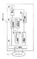
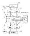
図2は、本実施例のスイッチ100の構成の一例を示す図である。図2に示すように、本実施例のスイッチ100は、前記したオブジェクトIDの書き換えを行うオブジェクトID書き換え部101と、ファイルアクセス管理部102と、パケット処理部103と、ファイルシステム補完処理部104と、擬似ファイルシステム105と、仮想スナップショット管理部106と、仮想スナップショットリンク情報107と、を備えている。 FIG. 2 is a diagram illustrating an example of the configuration of the
パケット処理部103は、ネットワーク2を介してクライアント1およびサーバ3から受信したパケットを解析して、パケットに含まれるデータをファイルアクセス管理部102に出力し、ファイルアクセス管理部102から出力されたデータをパケット化して、ネットワーク2を介してクライアント1およびサーバ3に送信する。 The
ファイルアクセス管理部102は、パケット処理部103から出力されたデータを入力して解析し、パケット処理部103が受信したパケットの転送先を決定する。 The file
オブジェクトID書き換え部101は、ファイルアクセス管理部102が決定するパケットの転送先に応じて、前述のデータに含まれるオブジェクトIDの書き換えを行う。 The object
擬似ファイルシステム105は、図1に示した複数のサーバ3のファイルシステムから構成されている複数のディレクトリツリーを組み合わせ、1つの統合ディレクトリツリーとして管理するためのシステムである。 The
ファイルシステム補完処理部104は、クライアント1からのファイルアクセス要求が、複数サーバ3もしくは複数のファイルシステム層4等の複数の送信先に渡ってファイルアクセスを必要とする場合の補完処理を行う。 The file system
仮想スナップショット管理部106は、サーバ3に対してスナップショットの指示を行う。また仮想スナップショット管理部106は、スナップショット作成時における擬似ファイルシステム(PFS)105のファイルシステム構造に対応して複数のスナップショットの間にリンクを張る制御も行う。なお、本実施例において、スナップショット、バックアップ、リストア処理は、各サーバ3で行われる。 The virtual
仮想スナップショット管理部106により、複数のサーバ3で作成された複数のスナップショットが、擬似ファイルシステム105の統合化ディレクトリツリーと対応するようにリンクが張られるが、仮想スナップショットリンク情報107は、複数のスナップショットのリンク情報(つなぎ目での接続先のポインタ情報)を記憶保持する。スイッチ100の擬似ファイルシステム105は、サーバ3におけるデータの変更に応じて変更されるが、仮想スナップショットリンク情報107は、スナップショット作成時の仮想スナップショットの固定化されたイメージである。したがって、仮想スナップショットリンク情報107に基づき、スナップショット作成時点での擬似ファイルシステム105を復元することができる。 The virtual
本実施例において、スイッチ100は、後述するように、擬似ファイルシステム105において、各サーバ3のディレクトリツリーの接続部の情報を記憶管理する構成とされているのと同様、仮想スナップショットリンク情報107として、各サーバ3のスナップショットの接続部(つなぎ目)の情報を記憶管理している。仮想スナップショットリンク情報107は、スナップショットの世代に対応して世代管理される。すなわち、予め定められた所定数の世代分、仮想スナップショットリンク情報107が記憶保持される。 In this embodiment, as will be described later, in the
スイッチ100は、ファイルアクセスの要求パケットおよび応答パケットを、クライアント1もしくはサーバ3へ適切に振り分ける機能に加え、複数のサーバ3のファイルシステム4上に形成されている複数のディレクトリツリーを、擬似ファイルシステム105のディレクトリツリーに統合することによって、複数のサーバ3における個々のファイルシステム4の存在をクライアント1に意識させることなく、スイッチ100の擬似ファイルシステム105のみにアクセスしているかのように振舞わせる機能を有している。 In addition to the function of appropriately distributing the file access request packet and the response packet to the
擬似ファイルシステム105は、サーバ3によりネットワーク2を介してアクセス可能なものとして公開されているファイルシステム4上の複数のディレクトリツリーにおけるツリー構造を自在に組み合わせて、1つのディレクトリツリーにマッピングする。本実施例では、図2に示したスイッチ100のオブジェクトID書き換え部101、ファイルアクセス管理部102、パケット処理部103、ファイルシステム補完処理部104、仮想スナップショット管理部106の各部について、スイッチ100を構成するコンピュータ上で実行されるプログラムにより、それぞれの処理・機能を実現するようにしてもよい。 The
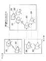
図3は、図2の擬似ファイルシステム105のディレクトリツリー200の一例を示す図である。図3に示すように、擬似ファイルシステム105は、サーバ3Aで公開されているディレクトリb(221)、およびサーバ3Bで公開されているディレクトリc(222)からのディレクトリツリーのツリー構造を、擬似ファイルシステム105上に形成されたルートディレクトリ220(/)のサブディレクトリからのディレクトリツリーとしてマッピングする。擬似ファイルシステムディレクトリツリー200のルートディレクトリ220は、ディレクトリ221と222へのポインタを含む。擬似ファイルシステム105は、サーバBで公開されているディレクトリe(224)からのディレクトリツリーのツリー構造を、ディレクトリb(221)からのディレクトリツリーの下層に存在するディレクトリf(223)のサブディレクトリからのディレクトリツリーとして登録することによって、擬似ファイルシステムディレクトリツリー200を生成する。本実施例のスイッチ装置では、擬似ファイルシステムディレクトリツリー200上におけるディレクトリ名は、サーバ3のファイルシステム4で設定されたディレクトリ名と必ずしも同一にする必要はなく、別のディレクトリ名を設定して、クライアント1に公開してもよい。 FIG. 3 is a diagram showing an example of the
スイッチ100において、擬似ファイルシステム105は、擬似ファイルシステムディレクトリツリー200のツリー構造のみを管理しており、オブジェクトのデータ、属性情報、各ファイルシステム4の接合部以外のツリー構造等は、すべてサーバ3側で管理している。例えば図3の擬似ファイルシステムディレクトリツリー200において、例えばルートディレクトリ220のノード接続部等のツリー情報を記憶管理する。図2の仮想スナップショットリンク情報107として、スナップショット作成時における擬似ファイルシステムディレクトリツリー200の接続部のツリー情報のみを記憶管理し、接続部以外の各ツリー構造は、対応するサーバ3におけるスナップショットとして管理される。かかる構成は、本発明の主要な特徴の1つをなしている。 In the
そして、スイッチ100では、複数のファイルシステム4を結合しているツリー部分のみの名前解決処理を行い、その他(接合部以外)のツリー部分については、サーバ3に処理を任せている。 In the
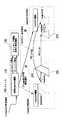
次に、本実施例の動作の具体例について説明する。図4は、本発明の一実施例の動作を説明する模式図である。図4において、仮想スナップショット機能110は、図2の仮想スナップショット管理部106に対応しており、スイッチング機能・仮想化管理機能120は、図2の、パケット処理部103、ファイルアクセス管理部102、ファイルシステム補完処理部104、擬似ファイルシステム105、仮想スナップショットリンク情報107等からなる。特に制限されないが、以下では、サーバはNASデバイスとする。 Next, a specific example of the operation of this embodiment will be described. FIG. 4 is a schematic diagram for explaining the operation of one embodiment of the present invention. 4, the
スイッチ100は、スナップショット作成指示をうける(ステップ1)。この実施例では、スナップショット作成指示の入力は、ネットワーク経由またはスイッチ100にログインして行われる。あるいは、スイッチ100で定期的にスナップショット作成指示が発行される構成としてもよい。 The
仮想スナップショット機能110は、スナップ対象のファイルシステムに更新がかからないように、スイッチング機能・仮想化管理機能120に対して、フォワードの停止を指示する(ステップ2)。その際、スナップ対象のファイルシステムの完全な静止点を求めるため、スイッチ100において、クライアント1からの要求(Call)に対するサーバ3からの応答が戻っていることを確認(同期確認)する。同期がとれていない場合、サーバ3へのスナップショットの作成開始の指示は待ち状態とされる。この同期管理は、図2のファイルアクセス管理部102とパケット処理部103の連携によって行われる。 The
仮想スナップショット機能110は、スナップショット対応サーバ3A、3B(NAS)にスナップショット作成開始を通知する(ステップ3)。 The
そして、サーバ3におけるスナップショット作成完了の通知を受け、仮想スナップショット機能110は、スイッチング機能・仮想化管理機能120に対して、フォワードを再開する。 The
サーバ3A、3Bでスナップショット作成後、スイッチ100で、スナップショットディレクトリに、擬似ファイルシステム105に対応するリンク(PFS Link)を作成する(ステップ5)。例えば擬似ファイルシステムディレクトリツリー200が、図4の200(図3の200に対応)として示すようなものである場合(ディレクトリツリー200がサーバ3Aのファイルシステムのディレクトリツリー201とサーバ3Bのファイルシステムのディレクトリツリー202とを統合化したものである場合)、スナップショット作成開始通知の受信により、サーバ3Aでは、ディレクトリツリー201のイメージを「snapshotA.1」、サーバ3Bでは、ディレクトリツリー202のイメージを「snapshotB.1」として作成する。なお、「snapshotA」は、システム側で設定するスナップショットアクセス用のエイリアス名を表しており、「1」は、世代番号を表している。また、エイリアス名「snapshotA」、「snapshotB」は、単に、サーバ3A、3Bに対応させ判りやすくしたものであり、スナップショットのエイリアス名(サーバのスナップショットソフトウェアで設定される)は、サーバ間で、同一であってもよい。 After the snapshots are created by the
スイッチ100の擬似ファイルシステム105のディレクトリツリー200において、実ファイルシステム(サーバ3A)のディレクトリツリー201は、実ファイルシステム(サーバ3B)のディレクトリツリー202にリンク(PFS Link)をはっている。同様に、サーバ3Aで作成されたディレクトリツリー201のスナップショット「snapshotA.1」は、サーバ3Bで作成されたディレクトリツリー201のスナップショット「snapshotB.1」に対して、等価なリンク(PFS Link)をはるように設定する。具体的には、2つのスナップショット「snapshotA.1」と「snapshotB.1」との接続部について、リンク先のオブジェクトを指示するポインタ情報を保持する。前述したように、このリンク情報は、スイッチ100において、仮想スナップショットリンク情報107として、スナップショットの世代に対応させて記憶管理される。 In the
これにより、図1の各サーバ3で、それぞれ個別に作成された複数のスナップショットが、スナップショット作成時点における統合ディレクトリツリーに自動でマッピングされる。 As a result, a plurality of snapshots individually created in each
図5は、図4に示した本発明の処理シーケンスを説明する図である。サーバをNASとしている。スイッチ100は、スナップショット作成指示をうける(ステップ1)。 FIG. 5 is a diagram for explaining the processing sequence of the present invention shown in FIG. The server is NAS. The
仮想スナップショット機能110は、サーバ3A、3Bのファイルシステム構造に更新がかからないように、スイッチング機能・仮想化管理機能120に対して、フォワード停止指示を行う。スイッチング機能・仮想化管理機能120は、フォワードを停止し、同期を確認する。例えばクライアントからの要求(Call)に対するサーバ3A、3Bからの応答が戻っていることを確認する。 The
スイッチ100の仮想スナップショット機能110は、配下のスナップショット対応サーバ(NAS)3A、3Bに対して、スナップショット作成を通知する(ステップ3)。これは、rsh(remote shell)又はssh(secure shell)により、スイッチ100かサーバ3にてスナップショットコマンドを実行することで行われる。なお、仮想スナップショット機能110は、複数のスナップショット対応サーバに並列にスナップショットコマンドを送信してもよい。 The
スイッチ100は、各サーバ3A、3Bのスナップショット世代として、同一世代名をアサインしてもよい。この場合、世代名称は、スイッチ100からのスナップショット作成の通知に添付してもよい。 The
そして、仮想スナップショット機能110は、スイッチング機能・仮想化管理機能120に対して、フォワード再開を指示する(ステップ4)。 Then, the
スイッチング機能・仮想化管理機能120は、複数のスナップショット間で、擬似ファイルシステム105に対応させてリンクを作成する。スイッチング機能・仮想化管理機能120はリンク作成後、応答を仮想スナップショット機能110に送信し、仮想スナップショット機能110は端末に受理応答(accept)を送信する。 The switching function /
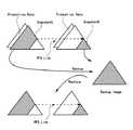
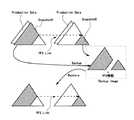
図6は、本発明の一実施例において、擬似ファイルシステムイメージでバックアップ/リストアする動作を説明するための図である。2つのファイルシステムのスナップショット(snapshotA、snapshotB)はリンク(PFS Link)をはっている。この状態で、2つのファイルシステムから、各スナップショットと同じイメージが読み出され、図1のスイッチ100の制御のもと、バックアップが行われ、複数のファイルシステムを1つに仮想化したファイルシステムのバックアップイメージが、テープ等に保管される。なお、図6において、"Production Data"(プロダクションデータ)は、例えばスナップショット(snapshotA、snapshotB)を作成した以降、変更された実データを模式的に表している。 FIG. 6 is a diagram for explaining an operation for performing backup / restore with a pseudo file system image in an embodiment of the present invention. Two file system snapshots (snapshotA, snapshotB) are linked (PFS Link). In this state, the same image as each snapshot is read from the two file systems, the backup is performed under the control of the
スナップショットを用いたバックアップについて説明する。スナップショットのデータは、スナップされたファイルシステムのデータと同じであるため、標準のファイルシステム構造に基づいて動作するバックアップコマンド(例えばcpio)を使用することができる。またrawディスクイメージを読み取るバックアップコマンド(例えばfscat)等では、スナップショット作成時にスナップされたファイルシステムが格納されていたディスクに対してディスクイメージのバックアップコマンドを使用したときに取得されるのと同一のファイルシステムのrawイメージが取得される。スナップショットの読み取りをサポートするシステムコールを用いた場合、スナップショット作成時に、スナップされたファイルシステムが格納されていたディスクの読み取りによって取得されるのと同一の結果が得られる(上記非特許文献1等参照)。 A backup using a snapshot will be described. Since the snapshot data is the same as the snapped file system data, a backup command (eg cpio) that operates based on a standard file system structure can be used. Also, the backup command that reads the raw disk image (for example, fscat) is the same as that obtained when the disk image backup command is used for the disk on which the snapped file system was stored. A raw image of the file system is acquired. When a system call that supports reading of a snapshot is used, the same result as that obtained by reading the disk on which the snapped file system is stored can be obtained when the snapshot is created (
テープに保管されたバックイメージを1つのファイルシステムにリストアすると、スナップショット作成時点における1つの仮想化されたファイルシステムがそのまま復元される。 When the back image stored on the tape is restored to one file system, one virtualized file system at the time of creating the snapshot is restored as it is.
なお、図1のクライアント1が、NFSプロトコルにより、スイッチ100経由でサーバ3にマウントし、スナップショットを読み出し、バックアップユニット6にバックアップすることで、図6の処理を行うようにしてもよい。 The
図7は、バックアップサーバを用いて、図6に示した操作を行う例を模式的に示す図である。2つのファイルサーバ3(NAS#1、NAS#2)でそれぞれスナップショットをとり、スイッチ100(「NASスイッチ」という)は、2つのファイルサーバ3(NAS#1、NAS#2)の複数のスナップショットにリンクをはる。そして、2つのファイルサーバ3(NAS#1、NAS#2)のそれぞれのファイルシステムは、スイッチ100を介して、仮想化されたスナップショットと同じイメージで、バックアップサーバ7を介して、テープドライブ8にバックアップされる。これにより、1つのファイルシステムに仮想化された複数のファイルシステムのスナップ時点でのバックアップイメージ(仮想化されたファイルシステムのバックアップイメージ)が、バックアップされる。かかる構成は、本発明の主たる特徴の1つをなしている。 FIG. 7 is a diagram schematically illustrating an example in which the operation illustrated in FIG. 6 is performed using a backup server. The two file servers 3 (
そして、リストア時には、テープ8からスイッチ100を介さずにバックアップサーバ7より、1つのファイルサーバ3(NASデバイス)に、バックアップイメージをリストアする。当該ファイルサーバ3では、スナップ時点での仮想化されたファイルシステムを復元することができる。 At the time of restoration, the backup image is restored from the
本実施例において、バックアップサーバとサーバとを、NFSプロトコル以外のプロトコルで接続し、高速転送を行うようにしてもよい。またバックアップ用の記憶装置はテープに制限されず、他の任意の記録装置であってもよいことは勿論である。 In this embodiment, the backup server and the server may be connected by a protocol other than the NFS protocol to perform high-speed transfer. Further, the backup storage device is not limited to a tape, and may be any other recording device.
図8は、図7に示したバックアップサーバ7を備えたシステム構成の一例を示す図である。バックアップサーバ7とサーバ3(バックアップクライアント)は、NFSプロトコル以外のインタフェース(SCSI等)で接続されていてもよい。またバックアップサーバ7とスイッチ100とは、NFSプロトコル以外のインタフェースで接続されていてもよい。バックアップサーバ7とスイッチ100間での直接の通信接続を制御するインタフェース71を備えてもよい。 FIG. 8 is a diagram showing an example of a system configuration including the
図9は、本発明の他の実施例において、擬似ファイルシステムイメージでのバックアップ/リストアする動作を説明するための図である。2つのファイルシステムのスナップショット(snapshotA、snapshotB)同士は、擬似ファイルシステムディレクトリツリーに対応してリンク(PFS Link)が張られている。この状態で、仮想化されたスナップショットを用いて、2つのファイルシステムのバックアップが行われ、スナップショット作成時の擬似ファイルシステムディレクトリツリーのバックアップイメージがテープ等に保管される。なお、図9において、"Production Data"(プロダクションデータ)は、スナップショット作成時点以降、変更された実データを模式的に表している。 FIG. 9 is a diagram for explaining the backup / restore operation with a pseudo file system image in another embodiment of the present invention. Two file system snapshots (snapshotA, snapshotB) are linked (PFS Link) corresponding to the pseudo file system directory tree. In this state, two file systems are backed up using the virtualized snapshot, and a backup image of the pseudo file system directory tree at the time of creating the snapshot is stored on a tape or the like. In FIG. 9, “Production Data” (production data) schematically represents actual data that has been changed since the snapshot was created.
スイッチ100が、テープに保管されたバックアップイメージを、スイッチ100の擬似ファイルシステム情報(図2の仮想スナップショットリンク情報107)に基づき、リストア先を振分けることで、2つのファイルシステムにそれぞれリストアし、各ファイルシステムにおいて、スナップショット作成時点でのファイルシステムが復元される。そして、リストアされた2つのファイルシステムにより、スナップショット作成時の仮想ファイルシステムを復元することができる。 The
図10は、ファイルサーバ(バックアップクライアント)とスイッチとバックアップサーバとがNFSプロトコルを用いて、図9に示した操作を行う例を模式的に示す図である。2つのファイルサーバ3(NAS#1、NAS#2)でスナップショットをとり、スイッチ100(NASスイッチ)は、複数のスナップショットに、擬似ファイルシステムのディレクトリツリーに対応させてリンクをはり仮想化されたスナップショットを作成する。バックアップサーバ7は、スイッチ100を介してファイルサーバ3にマウントし、スナップショットを用いてバックアップする。その際、スイッチ100(NASスイッチ)によって仮想化されたスナップショットにしたがって、2つのファイルサーバ3(NAS#1、NAS#2)から読み出されたデータが、テープドライブ8にバックアップされ、これにより、擬似ファイルシステムのファイルシステム構造に対応したファイルシステムのバックアップが行われる。 FIG. 10 is a diagram schematically illustrating an example in which the file server (backup client), the switch, and the backup server perform the operation illustrated in FIG. 9 using the NFS protocol. Snapshots are taken by the two file servers 3 (
そして、リストア時には、バックアップサーバ7からスイッチ100を介して、複数のファイルサーバ(NASデバイス)へのバックアップデータの振分が行われる。リストア時におけるスイッチ100による、サーバ3へのリストアデータ(オブジェクト)の振分は、図2に示した構成において、仮想スナップショットリンク情報107に基づき、リストアデータが、どのサーバに対応するか判別し、振分が行われる。なお、バックアップデータは、スナップショット作成時点からの差分をバックアップするようにしてもよい。この場合、2つのサーバには、スナップショット作成時点からの差分が加えられたファイルシステムがリストアされる。 At the time of restoration, backup data is distributed from the
図11は、ファイルサーバ(バックアップクライアント)とバックアップサーバとがNFSプロトコル以外のプロトコルを用いて通信する場合のバックアップ/リストア処理を説明するための図である。2つのファイルシステムのスナップショット(snapshotA、snapshotB)同士は、スナップショット作成時の擬似ファイルシステムディレクトリツリーに対応させて、リンク(PFS Link)が張られている。この状態で、2つのファイルシステムのバックアップがそれぞれ行われ、さらに、スナップショット作成時の擬似ファイルシステム105の情報(ディレクトリーツリー情報)が、テープ8等に保管される。 FIG. 11 is a diagram for explaining backup / restore processing when the file server (backup client) and the backup server communicate using a protocol other than the NFS protocol. Two file system snapshots (snapshotA, snapshotB) are linked (PFS Link) in correspondence with the pseudo file system directory tree at the time of snapshot creation. In this state, two file systems are backed up, and information (directory tree information) of the
テープ8の2つのファイルシステムのバックアップイメージを、2つのファイルサーバのファイルシステムにリストアし、スナップショット作成時の擬似ファイルシステム情報をスイッチ100に格納することで、スイッチ100を介して、クライアント1からみたとき、当該スナップショット作成時における仮想ファイルシステムを復元することができる。 The backup images of the two file systems on the
図12は、ファイルサーバ(バックアップクライアント)とバックアップサーバとがNFS以外のプロトコルを用いて、図11に示した操作を行う例を模式的に示す図である。2つのファイルサーバ3(NAS#1、NAS#2)でスナップショットをとり、スイッチ100(NASスイッチ)は、2つのスナップショットのリンク(PFS Link)をはる。 FIG. 12 is a diagram schematically illustrating an example in which the file server (backup client) and the backup server perform the operation illustrated in FIG. 11 using a protocol other than NFS. Snapshots are taken by the two file servers 3 (
2つのファイルサーバ3(NAS#1、NAS#2)から、スイッチ100を介さず、直接に、バックアップサーバ7にそれぞれのデータが、SCSI等により転送され、テープ8等にバックアップする。バックアップサーバ7は、テープ8にストレージ装置のフルバックアップを行ってもよい。 The data is transferred from the two file servers 3 (
また、スイッチ100から、バックアップサーバ7にインタフェース71を介して擬似ファイルシステム情報(PFS情報;例えば図2の仮想スナップショットリンク情報107)が転送され、テープ8等に保管される。 Further, pseudo file system information (PFS information; for example, virtual
そして、リストア時には、バックアップサーバ7から、スイッチ100を介することなく、テープ8からそれぞれのバックアップイメージが、2つのファイルサーバ3(NASデバイス)にリストアされる。 At the time of restoration, the backup images are restored from the
そして、テープ8等にバックアップされた擬似ファイルシステム情報(PFS情報)は、バックアップサーバ7からインタフェース71を介してスイッチ100に転送され、リストアされる。 The pseudo file system information (PFS information) backed up to the
スイッチ100を介して、クライアントからみたとき、スナップショット作成時の仮想ファイルシステムを復元することができる。クライアントからのファイルアクセス要求において、オブジェクトIDにサーバ識別情報が挿入され、スイッチ100は、このサーバ識別情報に基づき、ファイルアクセス要求を宛先のサーバ3に転送する。クライアントにおいては、バックアップ/リストア前と同様、スナップショット作成時の仮想化されたファイルシステムのオブジェクトにアクセスすることができる。 When viewed from the client via the
なお、サーバにおける、バックアップ、リストアコマンドは、クライアントから、スイッチを介してサーバに転送してもよい。バックアップクライアントをなすファイルサーバからバックアップサーバに要求し、その要求を受け、バックアップサーバがファイルサーバのファイルシステムにマウントしバックアップをとるようにしてもよい。あるいはNDMPにしたがい、データ管理アプリケーション(DMA;Data management Application)が指示してもよい。 Note that backup and restore commands in the server may be transferred from the client to the server via the switch. A request may be made to the backup server from the file server that constitutes the backup client, and the backup server may mount the file system of the file server in response to the request and take a backup. Alternatively, a data management application (DMA) may instruct according to NDMP.
このように、本実施例によれば、仮想化されたスナップショットを用いて、複数のファイルシステムを仮想化した1つのファイルシステムのバックアップイメージをとることで、複数のファイルシステムと仮想化したファイルシステムとのマッピングを管理者がとることは不要とされ、保守管理を特段に容易化しており、保守管理の負担を軽減しながら、データの安全性、システムの信頼性を確保することができる。 As described above, according to the present embodiment, a virtualized snapshot is used to take a backup image of one file system obtained by virtualizing a plurality of file systems, so that a plurality of file systems and virtualized files can be obtained. It is unnecessary for the administrator to perform mapping with the system, and maintenance management is particularly facilitated, and data safety and system reliability can be ensured while reducing the burden of maintenance management.
なお、上記実施例では、NASを例に説明したが、本発明は、NASに限定されるものでないことは勿論であり、ネットワーク接続される任意のファイルサーバに適用可能である。以上、本発明を上記実施例に即して説明したが、本発明は、上記実施例の構成にのみ限定されるものでなく、本発明の範囲内で当業者であればなし得るであろう各種変形、修正を含むものである。 In the above embodiment, NAS has been described as an example. However, the present invention is not limited to NAS and can be applied to any file server connected to a network. The present invention has been described with reference to the above-described embodiments. However, the present invention is not limited to the configurations of the above-described embodiments, and various modifications that can be made by those skilled in the art within the scope of the present invention. Includes deformation and modification.
1 クライアント
2 ネットワーク
3 サーバ
4 ファイルシステム層
5 記憶装置
6 バックアップユニット
7 バックアップサーバ
8 テープドライブユニット
71 インタフェース
100 スイッチ
101 オブジェクトID書き換え部
102 ファイルアクセス管理部
103 パケット処理部
104 ファイルシステム補完処理部
105 擬似ファイルシステム
106 仮想スナップショット管理部
107 仮想スナップショットリンク情報
110 仮想スナップショット機能
120 スイッチング機能・仮想化管理機能
200 擬似ファイルシステム・ディレクトリツリー
201、202 ディレクトリツリー
220 ルートディレクトリ
221、222、223、224 ディレクトリDESCRIPTION OF
Claims (48)
Translated fromJapaneseそれぞれがファイルシステムを備えた複数のファイル装置と、
前記端末と、前記複数のファイル装置との間に論理的に配置され、前記端末からみて仮想的に、複数のファイルシステムを1つのディレクトリツリーに結合して1つの擬似ファイルシステムを構成する中間装置と、
を備え、
前記中間装置は、複数の前記ファイル装置のそれぞれに対して、ある時点でのファイルシステムの固定化されたイメージであるスナップショットの作成の実行開始を指示する手段を備え、
複数の前記ファイル装置では、前記中間装置からスナップショット作成の実行開始の指示を受けてそれぞれスナップショットを作成し、
前記中間装置は、複数の前記ファイル装置でそれぞれ作成された複数の前記スナップショットが、スナップショット作成時における、前記擬似ファイルシステムに対応するように、複数の前記スナップショット間を接続し、前記スナップショット間のつなぎ目を管理する手段をさらに備えている、ことを特徴とするファイルアクセスサービスシステム。At least one terminal;
A plurality of file devices each having a file system;
An intermediate device that is logically arranged between the terminal and the plurality of file devices, and virtually combines the plurality of file systems into one directory tree as viewed from the terminal to constitute one pseudo file system. When,
With
The intermediate device includes means for instructing each of the plurality of file devices to start execution of creating a snapshot that is a fixed image of the file system at a certain point in time,
In the plurality of file devices, in response to an instruction to start execution of snapshot creation from the intermediate device, each creates a snapshot,
The intermediate device connects the plurality of snapshots so that the plurality of snapshots respectively created by the plurality of file devices correspond to the pseudo file system at the time of creating thesnapshot, and A file access service system further comprising meansfor managing a joint between shots .
複数の前記スナップショット同士のつなぎ目での接続先のポインタ情報を保持する、ことを特徴とする請求項1記載のファイルアクセスサービスシステム。The intermediate device, as snapshot information corresponding to the pseudo file system,
The file access service system according to claim 1, wherein pointer information of a connection destination at a joint between the plurality of snapshots is held.
前記バックアップ制御装置は、バックアップ時、前記中間装置を介して前記複数のファイル装置の複数のファイルシステムを受け取り、前記複数のファイルシステムを仮想化した1つのファイルシステム構造として、バックアップ記録装置にバックアップする、ことを特徴とする請求項1記載のファイルアクセスサービスシステム。Equipped with a backup control device,
The backup control device receives a plurality of file systems of the plurality of file devices via the intermediate device at the time of backup, and backs up the backup recording device as a single file system structure in which the plurality of file systems are virtualized. The file access service system according to claim 1.
前記バックアップ制御装置が、前記中間装置と通信するインタフェースを備え、
前記バックアップ制御装置は、バックアップ時、前記中間装置を介して、前記複数のファイル装置の複数のファイルシステムを受け取り、前記複数のファイルシステムを仮想化した1つのファイルシステム構造として、バックアップ記録装置にバックアップする、ことを特徴とする請求項1記載のファイルアクセスサービスシステム。A backup control device that communicates with a plurality of the file devices;
The backup control device comprises an interface for communicating with the intermediate device;
The backup control device receives a plurality of file systems of the plurality of file devices via the intermediate device at the time of backup, and backs up the backup recording device as a single file system structure in which the plurality of file systems are virtualized. The file access service system according to claim 1, wherein:
前記中間装置は、前記バックアップ制御装置から受け取ったバックアップデータを、複数の前記ファイルシステムを1つのファイルシステムとしてみせるための擬似ファイルシステム情報に対応させて、複数の前記ファイル装置に振分けてリストアする、ことを特徴とする請求項9記載のファイルアクセスサービスシステム。The backup control device supplies backup data of the backup recording device to the intermediate device at the time of restoration,
The intermediate device restores the backup data received from the backup control device in correspondence with the pseudo file system information for making the plurality of file systems appear as one file system and distributed to the plurality of file devices. The file access service system according to claim 9.
前記バックアップ制御装置が、前記中間装置と通信するインタフェースを備え、
前記バックアップ制御装置は、バックアップ時、前記中間装置を介して、前記複数のファイル装置の複数のスナップショットを受け取り、前記複数のスナップショットにはリンクが張られており、リンクが張られた前記複数のスナップショットをバックアップ記録装置にバックアップする、ことを特徴とする請求項1記載のファイルアクセスサービスシステム。A backup control device that communicates with a plurality of the file devices;
The backup control device comprises an interface for communicating with the intermediate device;
The backup control device receives a plurality of snapshots of the plurality of file devices via the intermediate device at the time of backup, and the plurality of snapshots are linked, and the plurality of linked links 2. The file access service system according to claim 1, wherein the snapshot is backed up to a backup recording device.
前記中間装置は、前記複数のスナップショットを、複数の前記ファイル装置に振分けて転送し、
前記複数のファイル装置では、それぞれに転送された前記スナップショットを用いてファイルシステムをリストアする、ことを特徴とする請求項11記載のファイルアクセスサービスシステム。The backup control device supplies backup data of the backup recording device to the intermediate device at the time of restoration,
The intermediate device distributes and transfers the plurality of snapshots to the plurality of file devices,
12. The file access service system according to claim 11, wherein the plurality of file devices restore the file system using the snapshot transferred to each of the plurality of file devices.
前記バックアップ制御装置が、前記中間装置と通信するインタフェースを備え、
前記バックアップ制御装置は、バックアップ時、前記中間装置より、複数の前記ファイルシステムを1つのファイルシステムとしてみせるための、擬似ファイルシステム情報を受け、前記擬似ファイルシステム情報と実際のファイルシステムのバックアップデータと組でバックアップ記録装置にバックアップする、ことを特徴とする請求項1記載のファイルアクセスサービスシステム。A backup control device that communicates with a plurality of the file devices;
The backup control device comprises an interface for communicating with the intermediate device;
The backup control device receives pseudo file system information for showing a plurality of the file systems as one file system from the intermediate device at the time of backup, and the pseudo file system information, backup data of the actual file system, 2. The file access service system according to claim 1, wherein backup is performed in pairs on a backup recording device.
前記スイッチ装置は、前記クライアントからのファイルアクセス要求を受信し、前記ファイルアクセス要求を適切なサーバ装置に振り分けて転送し、前記サーバ装置から送信された前述のファイルアクセス要求に対する応答を受信し、ファイルアクセス要求を送信した端末へとその応答を転送する、ことを特徴とする請求項1乃至14のいずれか一に記載のファイルアクセスサービスシステム。The intermediate device is composed of a switch device logically arranged between the terminal as a client and a server device that constitutes the file device;
The switch device receives a file access request from the client, distributes and transfers the file access request to an appropriate server device, receives a response to the file access request transmitted from the server device, 15. The file access service system according to claim 1, wherein the response is transferred to the terminal that has transmitted the access request.
前記オブジェクトを管理する前記サーバ装置に転送し、
前記要求に対する前記サーバ装置からの応答を前記要求の送信元であるクライアントに転送し、
転送する応答に前記オブジェクトを識別するために、前記サーバ装置で生成された元オブジェクトIDが含まれている場合には、前記元オブジェクトIDに対応するオブジェクトを管理するサーバ装置を他のサーバ装置から識別するためのサーバ識別情報を挿入し、前記元オブジェクトIDを情報付帯オブジェクトIDに書き換え、転送する要求に、前記情報付帯オブジェクトIDが含まれている場合には、前記情報付帯オブジェクトIDを前記元オブジェクトIDに復元する手段を備えている、ことを特徴とする請求項15記載のファイルアクセスサービスシステム。The switch device sends a request regarding an object transmitted from the client.
Transfer to the server device managing the object,
A response from the server device to the request is forwarded to the client that is the transmission source of the request;
If the original object ID generated by the server device is included in the response to be transferred, the server device managing the object corresponding to the original object ID is transferred from another server device. Server identification information for identification is inserted, the original object ID is rewritten to an information incidental object ID, and the information incidental object ID is included in the request to rewrite and transfer the information incidental object ID. 16. The file access service system according to claim 15, further comprising means for restoring the object ID.
前記スイッチ装置が、所定のレイヤ情報を利用して前記サーバの装置振分を行う、ことを特徴とする請求項15記載のファイルアクセスサービスシステム。The server device is a NAS (Network Attached Storage) device,
16. The file access service system according to claim 15, wherein the switch device performs device allocation of the server using predetermined layer information.
それぞれがファイルシステムを備えた複数のファイル装置と、
前記端末と、前記複数のファイル装置との間に論理的に配置され、前記端末からみて仮想的に、複数のファイルシステムを1つのディレクトリツリーに結合して1つの擬似ファイルシステムを構成する中間装置と、
を備えたファイルアクセスサービスシステムのバックアップ方法であって、
前記中間装置が、複数の前記ファイル装置に対して、ある時点でのファイルシステムの固定化されたイメージであるスナップショットの作成の実行開始の指示をそれぞれ分配する工程と、
複数の前記ファイル装置では、前記中間装置から前記スナップショット実行開始の指示を受けて、それぞれスナップショットを作成する工程と、
前記中間装置は、複数の前記ファイル装置でそれぞれ作成された複数の前記スナップショットが、スナップショット作成時における前記擬似ファイルシステムに対応するように、作成された複数の前記スナップショット間を接続し、前記スナップショット間のつなぎ目を管理する工程と、
を含む、ことを特徴とするバックアップ方法。At least one terminal;
A plurality of file devices each having a file system;
An intermediate device that is logically arranged between the terminal and the plurality of file devices, and virtually combines the plurality of file systems into one directory tree as viewed from the terminal to constitute one pseudo file system. When,
A file access service system backup method comprising:
The intermediate device distributes to each of the plurality of file devices an instruction to start execution of creating a snapshot, which is a fixed image of the file system at a certain point in time;
In a plurality of the file devices, receiving a snapshot execution start instruction from the intermediate device, respectively, creating a snapshot,
The intermediate device connects the plurality of created snapshots so that the plurality of snapshots respectively created by the plurality of file devices correspond to the pseudo file system at the time of snapshot creation, Managing a joint between the snapshots ;
Including a backup method.
バックアップ時に、前記バックアップ制御装置が、前記中間装置を介して、前記複数のファイル装置の複数のファイルシステムを受け取り、前記複数のファイルシステムを仮想化した1つのファイルシステム構造としてバックアップ記録装置にバックアップする、ことを特徴とする請求項19記載のバックアップ方法。Provide a backup control device,
At the time of backup, the backup control device receives a plurality of file systems of the plurality of file devices via the intermediate device, and backs up to a backup recording device as one file system structure in which the plurality of file systems are virtualized. 20. The backup method according to claim 19, wherein:
前記バックアップ制御装置は、バックアップ時、前記中間装置を介して、前記複数のファイル装置の複数のファイルシステムを受け取り、前記複数のファイルシステムを仮想化した1つのファイルシステム構造として、バックアップ記録装置にバックアップする、ことを特徴とする請求項19記載のバックアップ方法。A backup control device is provided for communication connection with the plurality of file devices and the intermediate device,
The backup control device receives a plurality of file systems of the plurality of file devices via the intermediate device at the time of backup, and backs up the backup recording device as a single file system structure in which the plurality of file systems are virtualized. The backup method according to claim 19, wherein:
前記中間装置は、複数の前記ファイルシステムを1つのファイルシステムとしてみせるための、擬似ファイルシステム情報に基づき、バックアップデータを複数の前記ファイル装置に振分てリストアする工程と、
を含む、ことを特徴とするリストア方法。When restoring data backed up by the method of claim 27, the backup control device supplies backup data of the backup recording device to the intermediate device at the time of restoration;
The intermediate device, based on pseudo file system information for showing the plurality of file systems as one file system, restoring backup data to the plurality of file devices; and
A restore method characterized by comprising:
前記バックアップ制御装置が、バックアップ時、前記中間装置を介して、前記複数のファイル装置の複数のスナップショットを受け取り、前記複数のスナップショットにはリンクが張られており、前記リンクが張られた前記複数のスナップファイルを、バックアップ記録装置にバックアップする、ことを特徴とする請求項19記載のバックアップ方法。A backup control device is provided for communication connection with the plurality of file devices and the intermediate device,
The backup control device receives a plurality of snapshots of the plurality of file devices via the intermediate device at the time of backup, and the plurality of snapshots are linked, and the link is stretched The backup method according to claim 19, wherein a plurality of snap files are backed up to a backup recording device.
前記中間装置は、前記複数のスナップショットを、複数の前記ファイル装置に振分けて転送する工程と、
前記複数のファイル装置では、それぞれに転送された前記スナップショットに基づきファイルシステムをリストアする工程と
を含む、ことを特徴とするリストア方法。When restoring the data backed up by the method according to claim 29, the backup control device supplies the plurality of snapshots backed up by the backup recording device to the intermediate device;
The intermediate device distributes and transfers the plurality of snapshots to the plurality of file devices; and
Restoring the file system based on the snapshot transferred to each of the plurality of file devices.
前記バックアップ制御装置は、バックアップ時、前記中間装置より、複数の前記ファイルシステムを1つのファイルシステムとしてみせるための、擬似ファイルシステム情報を受け、前記擬似ファイルシステム情報と実際のファイルシステムのバックアップデータと組でバックアップ記録装置にバックアップする、ことを特徴とする請求項19記載のバックアップ方法。A backup control device is provided for communication connection with the plurality of file devices and the intermediate device,
The backup control device receives pseudo file system information for showing a plurality of the file systems as one file system from the intermediate device at the time of backup, and the pseudo file system information, backup data of the actual file system, The backup method according to claim 19, wherein backup is performed in pairs on a backup recording device.
前記スイッチ装置は、前記クライアントからのファイルアクセス要求を受信し、前記ファイルアクセス要求を適切なサーバ装置に振り分けて転送し、前記サーバ装置から送信された前述のファイルアクセス要求に対する応答を受信し、ファイルアクセス要求を送信した端末へとその応答を転送する、ことを特徴とする請求項19乃至26、28、29、31のいずれか一に記載のバックアップ方法。The intermediate device is composed of a switch device logically arranged between the terminal as a client and a server device that constitutes the file device;
The switch device receives a file access request from the client, distributes and transfers the file access request to an appropriate server device, receives a response to the file access request transmitted from the server device, The backup method according to any one of claims 19 to 26, 28, 29, and 31, wherein the response is transferred to the terminal that has transmitted the access request.
前記要求に対する前記サーバからの応答を前記要求の送信元であるクライアントに転送し、
転送する応答に前記オブジェクトを識別するために、前記サーバで生成された元オブジェクトIDが含まれている場合には、前記元オブジェクトIDに対応するオブジェクトを管理するサーバを他のサーバから識別するためのサーバ識別情報を挿入し、前記元オブジェクトIDを情報付帯オブジェクトIDに書き換え、転送する要求に、前記情報付帯オブジェクトIDが含まれている場合には、前記情報付帯オブジェクトIDを前記元オブジェクトIDに復元する、ことを特徴とする請求項33記載のバックアップ方法。The switch device forwards a request regarding the object transmitted from the client to the server managing the object;
Forwarding the response from the server to the request to the client that is the source of the request;
In order to identify the object managing the object corresponding to the original object ID from other servers when the original object ID generated by the server is included in the response to be transferred. Server identification information is inserted, the original object ID is rewritten to an information incidental object ID, and the information incidental object ID is included in the request for transfer, the information incidental object ID is set as the original object ID. The backup method according to claim 33, wherein the restoration is performed.
前記スイッチ装置が、所定のレイヤ情報を利用してサーバの振分けを行う、ことを特徴とする請求項33記載のバックアップ方法。The server device is a NAS (Network Attached Storage) device,
34. The backup method according to claim 33, wherein the switch device performs server distribution using predetermined layer information.
複数の前記ファイルサーバに対して、ある時点でのファイルシステムの固定化されたイメージであるスナップショットの作成の実行開始の指示をそれぞれ分配する手段と、
前記スナップショット実行開始の指示を受けた複数の前記ファイルサーバでそれぞれ作成された複数の前記スナップショットに対して、スナップショット作成時における、前記擬似ファイルシステムに対応するように、複数の前記スナップショット間を接続し、前記スナップショット間のつなぎ目を管理する手段と、
を備えている、ことを特徴とするスイッチ装置。It is logically arranged between at least one client and a plurality of file servers each having a file system. Virtually viewed from the client, a plurality of file systems are combined into one directory tree to form a single directory tree. A switch device constituting a pseudo file system,
Means for distributing an instruction to start execution of creation of a snapshot, which is a fixed image of a file system at a certain time point, to the plurality of file servers;
A plurality of the snapshots corresponding to the pseudo file system at the time of creating the snapshot for the plurality of snapshots respectively created by the plurality of file servers that have received an instruction to start the snapshot execution Meansfor connecting and managing a joint between the snapshots ;
The switch apparatus characterized by the above-mentioned.
複数の前記ファイルサーバに対して、ある時点でのファイルシステムの固定化されたイメージであるスナップショットの作成の実行開始の指示をそれぞれ分配する処理と、
前記スナップショット実行開始の指示を受けた複数の前記ファイルサーバでそれぞれ作成された複数の前記スナップショットに対して、スナップショット作成時における、前記擬似ファイルシステムに対応するように複数の前記スナップショット間を接続し、前記スナップショット間のつなぎ目を管理する処理と、
を実行させるプログラム。It is logically arranged between at least one client and a plurality of file servers each having a file system. Virtually viewed from the client, a plurality of file systems are combined into one directory tree to form a single directory tree. In the computer constituting the switch device constituting the pseudo file system,
A process of distributing an instruction to start execution of creating a snapshot, which is a fixed image of the file system at a certain time, to the plurality of file servers;
For the plurality of snapshots respectively created by the plurality of file servers that have received an instruction to start execution of the snapshot, a plurality of the snapshots are associated with the pseudo file system at the time of creating the snapshot. Andmanaging the joint between the snapshots ,
A program that executes
前記擬似ファイルシステムに対応するスナップショット情報として、複数の前記スナップショット同士のつなぎ目での接続先のポインタ情報を保持する処理を、前記コンピュータに実行させるプログラム。The program of claim 43,
A program that causes the computer to execute processing for holding pointer information of connection destinations at joints between a plurality of snapshots as snapshot information corresponding to the pseudo file system.
スナップショットの実行開始に際して、それぞれの前記ファイルシステムへのアクセスを停止するように制御する処理を、前記コンピュータに実行させるプログラム。The program of claim 43,
A program that causes the computer to execute a process of controlling to stop access to each file system when starting execution of a snapshot.
前記ファイルサーバと前記クライアントとのファイルアクセスに関する同期を確認したのち、複数の前記ファイルサーバでスナップショットが実行されるように制御する処理を、前記コンピュータに実行させるプログラム。The program of claim 45,
A program that causes the computer to execute a process of controlling a snapshot to be executed by a plurality of the file servers after confirming synchronization regarding file access between the file server and the client.
スナップショット作成後、それぞれの前記ファイルシステムへのアクセスを再開するように制御する処理を、前記コンピュータに実行させるプログラム。The program of claim 45,
A program that causes the computer to execute a process of controlling to resume access to each file system after creating a snapshot.
前記ファイルシステムのスナップショット世代に対して、同一世代名を付与する処理を、前記コンピュータに実行させるプログラム。
The program according to claim 46,
A program that causes the computer to execute a process of assigning the same generation name to a snapshot generation of the file system.
Priority Applications (7)
| Application Number | Priority Date | Filing Date | Title |
|---|---|---|---|
| JP2004284378AJP4325524B2 (en) | 2004-09-29 | 2004-09-29 | Switch device and system, backup and restore method and program |
| US11/236,844US8346826B2 (en) | 2004-09-29 | 2005-09-28 | Switch device, system, backup method and computer program |
| CNB2005101041921ACN100369002C (en) | 2004-09-29 | 2005-09-29 | Switch device and system, and backup and restore method |
| CN2008100028406ACN101221521B (en) | 2004-09-29 | 2005-09-29 | Backup management and file access service system and method, exchange device |
| CNA2008100028410ACN101231603A (en) | 2004-09-29 | 2005-09-29 | Switch device, system, backup method and computer program |
| US12/046,208US20080162608A1 (en) | 2004-09-29 | 2008-03-11 | Switch device, system, backup method and computer program |
| US12/046,185US20080162607A1 (en) | 2004-09-29 | 2008-03-11 | Switch device, system, backup method and computer program |
Applications Claiming Priority (1)
| Application Number | Priority Date | Filing Date | Title |
|---|---|---|---|
| JP2004284378AJP4325524B2 (en) | 2004-09-29 | 2004-09-29 | Switch device and system, backup and restore method and program |
Publications (2)
| Publication Number | Publication Date |
|---|---|
| JP2006099406A JP2006099406A (en) | 2006-04-13 |
| JP4325524B2true JP4325524B2 (en) | 2009-09-02 |
Family
ID=36146665
Family Applications (1)
| Application Number | Title | Priority Date | Filing Date |
|---|---|---|---|
| JP2004284378AExpired - Fee RelatedJP4325524B2 (en) | 2004-09-29 | 2004-09-29 | Switch device and system, backup and restore method and program |
Country Status (3)
| Country | Link |
|---|---|
| US (3) | US8346826B2 (en) |
| JP (1) | JP4325524B2 (en) |
| CN (3) | CN101231603A (en) |
Cited By (1)
| Publication number | Priority date | Publication date | Assignee | Title |
|---|---|---|---|---|
| US12373399B2 (en) | 2016-04-26 | 2025-07-29 | Umbra Technologies Ltd. (Uk) | Data beacon pulser(s) powered by information slingshot |
Families Citing this family (127)
| Publication number | Priority date | Publication date | Assignee | Title |
|---|---|---|---|---|
| US8037264B2 (en)* | 2003-01-21 | 2011-10-11 | Dell Products, L.P. | Distributed snapshot process |
| JP4466001B2 (en)* | 2003-08-06 | 2010-05-26 | 株式会社日立製作所 | Snapshot acceleration method |
| US8458295B1 (en)* | 2005-11-14 | 2013-06-04 | Sprint Communications Company L.P. | Web content distribution devices to stage network device software |
| JP4795787B2 (en)* | 2005-12-09 | 2011-10-19 | 株式会社日立製作所 | Storage system, NAS server, and snapshot method |
| US20070214384A1 (en)* | 2006-03-07 | 2007-09-13 | Manabu Kitamura | Method for backing up data in a clustered file system |
| US20070282964A1 (en)* | 2006-06-06 | 2007-12-06 | International Business Machines Corporation | Method and apparatus for processing remote shell commands |
| US8457121B1 (en)* | 2006-08-01 | 2013-06-04 | Hewlett-Packard Development Company, L.P. | Heterogeneous network switch system |
| US8990270B2 (en)* | 2006-08-03 | 2015-03-24 | Hewlett-Packard Development Company, L. P. | Protocol virtualization for a network file system |
| JP2008077249A (en)* | 2006-09-19 | 2008-04-03 | Fujitsu Ltd | System environment restoration method |
| US7716186B2 (en)* | 2007-01-22 | 2010-05-11 | International Business Machines Corporation | Method and system for transparent backup to a hierarchical storage system |
| US8312046B1 (en)* | 2007-02-28 | 2012-11-13 | Netapp, Inc. | System and method for enabling a data container to appear in a plurality of locations in a super-namespace |
| US8768898B1 (en)* | 2007-04-26 | 2014-07-01 | Netapp, Inc. | Performing direct data manipulation on a storage device |
| US8412896B1 (en)* | 2007-04-27 | 2013-04-02 | Netapp, Inc. | Method and system for transparent restore of junction file types |
| JP5232406B2 (en)* | 2007-05-25 | 2013-07-10 | 株式会社日立製作所 | Information processing apparatus and method |
| US8117243B2 (en)* | 2008-02-21 | 2012-02-14 | Oracle America, Inc. | Dynamic transactional instantiation of system configuration using a virtual file system layer |
| US8769048B2 (en) | 2008-06-18 | 2014-07-01 | Commvault Systems, Inc. | Data protection scheduling, such as providing a flexible backup window in a data protection system |
| US8725688B2 (en) | 2008-09-05 | 2014-05-13 | Commvault Systems, Inc. | Image level copy or restore, such as image level restore without knowledge of data object metadata |
| JP5414223B2 (en)* | 2008-09-16 | 2014-02-12 | 株式会社日立ソリューションズ | Transfer data management system for Internet backup |
| JP2010097359A (en) | 2008-10-15 | 2010-04-30 | Hitachi Ltd | File management method and hierarchy management file system |
| US8291261B2 (en)* | 2008-11-05 | 2012-10-16 | Vulcan Technologies Llc | Lightweight application-level runtime state save-and-restore utility |
| US9270785B2 (en) | 2008-12-18 | 2016-02-23 | Citrix Systems, Inc. | System and method for a distributed virtual desktop infrastructure |
| US8566362B2 (en) | 2009-01-23 | 2013-10-22 | Nasuni Corporation | Method and system for versioned file system using structured data representations |
| JP5206864B2 (en)* | 2009-03-18 | 2013-06-12 | 富士通株式会社 | Update program, information processing apparatus, and update method |
| CN101841425B (en)* | 2009-12-25 | 2013-01-23 | 创新科存储技术有限公司 | Network backup method, device and system without proxy |
| US9792298B1 (en) | 2010-05-03 | 2017-10-17 | Panzura, Inc. | Managing metadata and data storage for a cloud controller in a distributed filesystem |
| US9811532B2 (en) | 2010-05-03 | 2017-11-07 | Panzura, Inc. | Executing a cloud command for a distributed filesystem |
| US9852149B1 (en) | 2010-05-03 | 2017-12-26 | Panzura, Inc. | Transferring and caching a cloud file in a distributed filesystem |
| US9852150B2 (en) | 2010-05-03 | 2017-12-26 | Panzura, Inc. | Avoiding client timeouts in a distributed filesystem |
| US8799413B2 (en)* | 2010-05-03 | 2014-08-05 | Panzura, Inc. | Distributing data for a distributed filesystem across multiple cloud storage systems |
| US8805967B2 (en)* | 2010-05-03 | 2014-08-12 | Panzura, Inc. | Providing disaster recovery for a distributed filesystem |
| US8799414B2 (en)* | 2010-05-03 | 2014-08-05 | Panzura, Inc. | Archiving data for a distributed filesystem |
| US8805968B2 (en)* | 2010-05-03 | 2014-08-12 | Panzura, Inc. | Accessing cached data from a peer cloud controller in a distributed filesystem |
| US8788628B1 (en)* | 2011-11-14 | 2014-07-22 | Panzura, Inc. | Pre-fetching data for a distributed filesystem |
| US10162722B2 (en)* | 2010-07-15 | 2018-12-25 | Veritas Technologies Llc | Virtual machine aware replication method and system |
| US8306950B2 (en)* | 2010-08-26 | 2012-11-06 | International Business Machines Corporation | Managing data access requests after persistent snapshots |
| US8799231B2 (en) | 2010-08-30 | 2014-08-05 | Nasuni Corporation | Versioned file system with fast restore |
| US8924360B1 (en) | 2010-09-30 | 2014-12-30 | Axcient, Inc. | Systems and methods for restoring a file |
| US8954544B2 (en) | 2010-09-30 | 2015-02-10 | Axcient, Inc. | Cloud-based virtual machines and offices |
| US8589350B1 (en)* | 2012-04-02 | 2013-11-19 | Axcient, Inc. | Systems, methods, and media for synthesizing views of file system backups |
| US9705730B1 (en) | 2013-05-07 | 2017-07-11 | Axcient, Inc. | Cloud storage using Merkle trees |
| US9235474B1 (en) | 2011-02-17 | 2016-01-12 | Axcient, Inc. | Systems and methods for maintaining a virtual failover volume of a target computing system |
| US10284437B2 (en) | 2010-09-30 | 2019-05-07 | Efolder, Inc. | Cloud-based virtual machines and offices |
| WO2012051298A2 (en) | 2010-10-12 | 2012-04-19 | Nasuni Corporation | Versioned file system with sharing |
| CN102012947A (en)* | 2010-12-16 | 2011-04-13 | 创新科存储技术有限公司 | Method and system for online backup of database |
| US10210169B2 (en)* | 2011-03-31 | 2019-02-19 | EMC IP Holding Company LLC | System and method for verifying consistent points in file systems |
| US8832394B2 (en)* | 2011-03-31 | 2014-09-09 | Emc Corporation | System and method for maintaining consistent points in file systems |
| US9996540B2 (en) | 2011-03-31 | 2018-06-12 | EMC IP Holding Company LLC | System and method for maintaining consistent points in file systems using a prime dependency list |
| JP5640151B2 (en)* | 2011-05-31 | 2014-12-10 | 株式会社日立製作所 | Computer and data management method by computer |
| WO2013056228A1 (en)* | 2011-10-13 | 2013-04-18 | Citrix Systems, Inc. | System and method for a distributed virtual desktop infrastructure |
| US9805054B2 (en) | 2011-11-14 | 2017-10-31 | Panzura, Inc. | Managing a global namespace for a distributed filesystem |
| US9804928B2 (en) | 2011-11-14 | 2017-10-31 | Panzura, Inc. | Restoring an archived file in a distributed filesystem |
| US8516210B2 (en)* | 2011-12-21 | 2013-08-20 | Microsoft Corporation | Application consistent snapshots of a shared volume |
| CN102662797A (en)* | 2012-04-11 | 2012-09-12 | 无锡华御信息技术有限公司 | Virtualization-based software backup method |
| CN102693173A (en)* | 2012-05-15 | 2012-09-26 | 记忆科技(深圳)有限公司 | File processing method based on snapshot and solid state disk with snapshot function |
| US20140068040A1 (en)* | 2012-09-04 | 2014-03-06 | Bank Of America Corporation | System for Enabling Server Maintenance Using Snapshots |
| US9785647B1 (en) | 2012-10-02 | 2017-10-10 | Axcient, Inc. | File system virtualization |
| US9852140B1 (en) | 2012-11-07 | 2017-12-26 | Axcient, Inc. | Efficient file replication |
| US9633216B2 (en) | 2012-12-27 | 2017-04-25 | Commvault Systems, Inc. | Application of information management policies based on operation with a geographic entity |
| US9152338B2 (en)* | 2013-02-21 | 2015-10-06 | International Business Machines Corporation | Snapshot management in hierarchical storage infrastructure |
| US9397907B1 (en) | 2013-03-07 | 2016-07-19 | Axcient, Inc. | Protection status determinations for computing devices |
| US9292153B1 (en) | 2013-03-07 | 2016-03-22 | Axcient, Inc. | Systems and methods for providing efficient and focused visualization of data |
| US9459968B2 (en) | 2013-03-11 | 2016-10-04 | Commvault Systems, Inc. | Single index to query multiple backup formats |
| US9152776B2 (en)* | 2013-04-30 | 2015-10-06 | Netapp, Inc. | Secure access-based enumeration of a junction or mount point on a clustered server |
| CN105339903B (en) | 2013-06-03 | 2019-02-19 | 慧与发展有限责任合伙企业 | Restore the method and system of file system object |
| WO2015050620A2 (en)* | 2013-07-16 | 2015-04-09 | Openpeak Inc. | Method and system for backing up and restoring a virtual file system |
| US9979783B2 (en) | 2014-01-21 | 2018-05-22 | Red Hat, Inc. | Distributed coordinated snapshots |
| WO2015125290A1 (en) | 2014-02-24 | 2015-08-27 | 富士通株式会社 | Service providing method, service providing device, and service providing program |
| US9798596B2 (en) | 2014-02-27 | 2017-10-24 | Commvault Systems, Inc. | Automatic alert escalation for an information management system |
| US10459892B2 (en) | 2014-04-23 | 2019-10-29 | Qumulo, Inc. | Filesystem hierarchical aggregate metrics |
| US9740574B2 (en) | 2014-05-09 | 2017-08-22 | Commvault Systems, Inc. | Load balancing across multiple data paths |
| US9852026B2 (en) | 2014-08-06 | 2017-12-26 | Commvault Systems, Inc. | Efficient application recovery in an information management system based on a pseudo-storage-device driver |
| US11249858B2 (en) | 2014-08-06 | 2022-02-15 | Commvault Systems, Inc. | Point-in-time backups of a production application made accessible over fibre channel and/or ISCSI as data sources to a remote application by representing the backups as pseudo-disks operating apart from the production application and its host |
| CN104408050A (en)* | 2014-10-28 | 2015-03-11 | 北京临近空间飞行器系统工程研究所 | Online automatic interpretation system and method of test data |
| US9720779B2 (en)* | 2014-11-27 | 2017-08-01 | Institute For Information Industry | Backup system and backup method thereof |
| EP3224744A4 (en) | 2014-11-28 | 2018-08-01 | Nasuni Corporation | Versioned file system with global lock |
| JP6450598B2 (en)* | 2015-01-19 | 2019-01-09 | 東芝メモリ株式会社 | Information processing apparatus, information processing method, and program |
| CN104657236A (en)* | 2015-03-11 | 2015-05-27 | 深圳市新岸通讯技术有限公司 | Embedded Linux file system based on 32-bit MCU (microprogrammable control unit) and operating method thereof |
| US11144520B2 (en)* | 2015-05-08 | 2021-10-12 | Adp, Llc | Information system with versioning descending node snapshot |
| US9766825B2 (en) | 2015-07-22 | 2017-09-19 | Commvault Systems, Inc. | Browse and restore for block-level backups |
| US10296368B2 (en) | 2016-03-09 | 2019-05-21 | Commvault Systems, Inc. | Hypervisor-independent block-level live browse for access to backed up virtual machine (VM) data and hypervisor-free file-level recovery (block-level pseudo-mount) |
| CN106339278A (en)* | 2016-08-24 | 2017-01-18 | 浪潮电子信息产业股份有限公司 | Data backup and recovery method of network file system |
| CN107784013B (en)* | 2016-08-30 | 2021-08-27 | 福建福昕软件开发股份有限公司 | Method for interconnecting dispersed documents for distributed management |
| CN107957918B (en)* | 2016-10-14 | 2019-05-10 | 腾讯科技(深圳)有限公司 | Data reconstruction method and device |
| CN106598785A (en)* | 2016-12-16 | 2017-04-26 | 广东美晨通讯有限公司 | File system backup and restoration method and device |
| US10838821B2 (en) | 2017-02-08 | 2020-11-17 | Commvault Systems, Inc. | Migrating content and metadata from a backup system |
| US11182340B2 (en)* | 2017-02-15 | 2021-11-23 | Paypal, Inc. | Data transfer size reduction |
| US10740193B2 (en) | 2017-02-27 | 2020-08-11 | Commvault Systems, Inc. | Hypervisor-independent reference copies of virtual machine payload data based on block-level pseudo-mount |
| US10891069B2 (en) | 2017-03-27 | 2021-01-12 | Commvault Systems, Inc. | Creating local copies of data stored in online data repositories |
| US10776329B2 (en) | 2017-03-28 | 2020-09-15 | Commvault Systems, Inc. | Migration of a database management system to cloud storage |
| US11074140B2 (en) | 2017-03-29 | 2021-07-27 | Commvault Systems, Inc. | Live browsing of granular mailbox data |
| US10664352B2 (en) | 2017-06-14 | 2020-05-26 | Commvault Systems, Inc. | Live browsing of backed up data residing on cloned disks |
| US10783114B2 (en) | 2018-01-12 | 2020-09-22 | Vmware, Inc. | Supporting glacier tiering of archived data in cloud/object storage |
| US10705922B2 (en) | 2018-01-12 | 2020-07-07 | Vmware, Inc. | Handling fragmentation of archived data in cloud/object storage |
| US10503444B2 (en)* | 2018-01-12 | 2019-12-10 | Vmware, Inc. | Object format and upload process for archiving data in cloud/object storage |
| US10503602B2 (en) | 2018-01-12 | 2019-12-10 | Vmware Inc. | Deletion and restoration of archived data in cloud/object storage |
| US10795927B2 (en) | 2018-02-05 | 2020-10-06 | Commvault Systems, Inc. | On-demand metadata extraction of clinical image data |
| US10754729B2 (en) | 2018-03-12 | 2020-08-25 | Commvault Systems, Inc. | Recovery point objective (RPO) driven backup scheduling in a data storage management system |
| US10789387B2 (en) | 2018-03-13 | 2020-09-29 | Commvault Systems, Inc. | Graphical representation of an information management system |
| US11360936B2 (en) | 2018-06-08 | 2022-06-14 | Qumulo, Inc. | Managing per object snapshot coverage in filesystems |
| US10860443B2 (en) | 2018-12-10 | 2020-12-08 | Commvault Systems, Inc. | Evaluation and reporting of recovery readiness in a data storage management system |
| US10534758B1 (en) | 2018-12-20 | 2020-01-14 | Qumulo, Inc. | File system cache tiers |
| CN110008067B (en)* | 2019-04-15 | 2020-07-07 | 苏州浪潮智能科技有限公司 | A method, device and distributed storage system for writable snapshot chain clone |
| US11308034B2 (en) | 2019-06-27 | 2022-04-19 | Commvault Systems, Inc. | Continuously run log backup with minimal configuration and resource usage from the source machine |
| CN112748991B (en)* | 2019-10-30 | 2024-09-13 | 伊姆西Ip控股有限责任公司 | Method, apparatus and computer program product for backing up data |
| US10795796B1 (en) | 2020-01-24 | 2020-10-06 | Qumulo, Inc. | Predictive performance analysis for file systems |
| US10860372B1 (en) | 2020-01-24 | 2020-12-08 | Qumulo, Inc. | Managing throughput fairness and quality of service in file systems |
| US11151001B2 (en) | 2020-01-28 | 2021-10-19 | Qumulo, Inc. | Recovery checkpoints for distributed file systems |
| US11775481B2 (en) | 2020-09-30 | 2023-10-03 | Qumulo, Inc. | User interfaces for managing distributed file systems |
| KR102491998B1 (en)* | 2020-12-04 | 2023-01-26 | (주)글루버 | Virtualization server, operating method of server virtualization system, and program using the same |
| US11157458B1 (en) | 2021-01-28 | 2021-10-26 | Qumulo, Inc. | Replicating files in distributed file systems using object-based data storage |
| US11461241B2 (en) | 2021-03-03 | 2022-10-04 | Qumulo, Inc. | Storage tier management for file systems |
| US11132126B1 (en)* | 2021-03-16 | 2021-09-28 | Qumulo, Inc. | Backup services for distributed file systems in cloud computing environments |
| US11567660B2 (en) | 2021-03-16 | 2023-01-31 | Qumulo, Inc. | Managing cloud storage for distributed file systems |
| US11669255B2 (en) | 2021-06-30 | 2023-06-06 | Qumulo, Inc. | Distributed resource caching by reallocation of storage caching using tokens and agents with non-depleted cache allocations |
| US11294604B1 (en) | 2021-10-22 | 2022-04-05 | Qumulo, Inc. | Serverless disk drives based on cloud storage |
| US11354273B1 (en) | 2021-11-18 | 2022-06-07 | Qumulo, Inc. | Managing usable storage space in distributed file systems |
| US11599508B1 (en) | 2022-01-31 | 2023-03-07 | Qumulo, Inc. | Integrating distributed file systems with object stores |
| US12346290B2 (en) | 2022-07-13 | 2025-07-01 | Qumulo, Inc. | Workload allocation for file system maintenance |
| US11722150B1 (en) | 2022-09-28 | 2023-08-08 | Qumulo, Inc. | Error resistant write-ahead log |
| US11729269B1 (en) | 2022-10-26 | 2023-08-15 | Qumulo, Inc. | Bandwidth management in distributed file systems |
| US11966592B1 (en) | 2022-11-29 | 2024-04-23 | Qumulo, Inc. | In-place erasure code transcoding for distributed file systems |
| CN116010365A (en)* | 2023-01-04 | 2023-04-25 | 上海通联金融服务有限公司 | A Multisystem Parallel File Exchange Mechanism |
| US12326912B2 (en) | 2023-10-03 | 2025-06-10 | T-Mobile Usa, Inc. | Caching system for presenting dashboard snapshots with quick response access to live dashboard data |
| US12292853B1 (en) | 2023-11-06 | 2025-05-06 | Qumulo, Inc. | Object-based storage with garbage collection and data consolidation |
| US11921677B1 (en) | 2023-11-07 | 2024-03-05 | Qumulo, Inc. | Sharing namespaces across file system clusters |
| US11934660B1 (en) | 2023-11-07 | 2024-03-19 | Qumulo, Inc. | Tiered data storage with ephemeral and persistent tiers |
| US12222903B1 (en) | 2024-08-09 | 2025-02-11 | Qumulo, Inc. | Global namespaces for distributed file systems |
Family Cites Families (28)
| Publication number | Priority date | Publication date | Assignee | Title |
|---|---|---|---|---|
| US5079695A (en)* | 1988-04-25 | 1992-01-07 | Hewlett-Packard Company | Object management facility which includes a snapshot facility for providing data transfer between two objects |
| US6604118B2 (en)* | 1998-07-31 | 2003-08-05 | Network Appliance, Inc. | File system image transfer |
| US5991763A (en)* | 1996-10-29 | 1999-11-23 | Sun Microsystems, Inc. | Method and apparatus for embedding concatenated data files into object files during runtime in a virtual file system |
| US6038639A (en)* | 1997-09-09 | 2000-03-14 | Storage Technology Corporation | Data file storage management system for snapshot copy operations |
| US6061770A (en)* | 1997-11-04 | 2000-05-09 | Adaptec, Inc. | System and method for real-time data backup using snapshot copying with selective compaction of backup data |
| US6212531B1 (en)* | 1998-01-13 | 2001-04-03 | International Business Machines Corporation | Method for implementing point-in-time copy using a snapshot function |
| US6173293B1 (en)* | 1998-03-13 | 2001-01-09 | Digital Equipment Corporation | Scalable distributed file system |
| JP3810577B2 (en) | 1999-03-26 | 2006-08-16 | 株式会社日立製作所 | Directory synchronization method |
| US7363633B1 (en)* | 2000-04-24 | 2008-04-22 | Microsoft Corporation | Registering and storing dependencies among applications and objects in a computer system and communicating the dependencies to a recovery or backup service |
| JP3879594B2 (en) | 2001-11-02 | 2007-02-14 | 日本電気株式会社 | Switch method, apparatus and program |
| PL351784A1 (en)* | 2002-01-21 | 2003-07-28 | Advanced Digital Broadcast Ltd | System for of storing data and method of recording them in that system |
| US7216135B2 (en)* | 2002-02-15 | 2007-05-08 | International Business Machines Corporation | File system for providing access to a snapshot dataset where disk address in the inode is equal to a ditto address for indicating that the disk address is invalid disk address |
| US6829617B2 (en)* | 2002-02-15 | 2004-12-07 | International Business Machines Corporation | Providing a snapshot of a subset of a file system |
| US7475098B2 (en)* | 2002-03-19 | 2009-01-06 | Network Appliance, Inc. | System and method for managing a plurality of snapshots |
| US7467167B2 (en)* | 2002-03-19 | 2008-12-16 | Network Appliance, Inc. | System and method for coalescing a plurality of snapshots |
| JP4211285B2 (en)* | 2002-05-24 | 2009-01-21 | 株式会社日立製作所 | Method and apparatus for virtual unification of network storage system |
| JP2004054607A (en) | 2002-07-19 | 2004-02-19 | Nec Corp | Switch device, method of distributed object management, and program |
| US6928514B2 (en)* | 2002-08-05 | 2005-08-09 | Lsi Logic Corporation | Method and apparatus for teaming storage controllers |
| US6996582B2 (en)* | 2002-10-03 | 2006-02-07 | Hewlett-Packard Development Company, L.P. | Virtual storage systems and virtual storage system operational methods |
| US20040088301A1 (en)* | 2002-10-31 | 2004-05-06 | Mallik Mahalingam | Snapshot of a file system |
| US7284016B2 (en)* | 2002-12-03 | 2007-10-16 | Emc Corporation | Client-server protocol for directory access of snapshot file systems in a storage system |
| US7236987B1 (en)* | 2003-02-28 | 2007-06-26 | Sun Microsystems Inc. | Systems and methods for providing a storage virtualization environment |
| US7139845B2 (en)* | 2003-04-29 | 2006-11-21 | Brocade Communications Systems, Inc. | Fibre channel fabric snapshot service |
| US20040254962A1 (en)* | 2003-06-12 | 2004-12-16 | Shoji Kodama | Data replication for enterprise applications |
| US6959313B2 (en)* | 2003-07-08 | 2005-10-25 | Pillar Data Systems, Inc. | Snapshots of file systems in data storage systems |
| JP4321705B2 (en)* | 2003-07-29 | 2009-08-26 | 株式会社日立製作所 | Apparatus and storage system for controlling acquisition of snapshot |
| US7225208B2 (en)* | 2003-09-30 | 2007-05-29 | Iron Mountain Incorporated | Systems and methods for backing up data files |
| US8645496B2 (en)* | 2004-09-07 | 2014-02-04 | Emc Corporation | Systems and methods for backing up data |
- 2004
- 2004-09-29JPJP2004284378Apatent/JP4325524B2/ennot_activeExpired - Fee Related
- 2005
- 2005-09-28USUS11/236,844patent/US8346826B2/ennot_activeExpired - Fee Related
- 2005-09-29CNCNA2008100028410Apatent/CN101231603A/enactivePending
- 2005-09-29CNCNB2005101041921Apatent/CN100369002C/ennot_activeExpired - Fee Related
- 2005-09-29CNCN2008100028406Apatent/CN101221521B/ennot_activeExpired - Fee Related
- 2008
- 2008-03-11USUS12/046,185patent/US20080162607A1/ennot_activeAbandoned
- 2008-03-11USUS12/046,208patent/US20080162608A1/ennot_activeAbandoned
Cited By (1)
| Publication number | Priority date | Publication date | Assignee | Title |
|---|---|---|---|---|
| US12373399B2 (en) | 2016-04-26 | 2025-07-29 | Umbra Technologies Ltd. (Uk) | Data beacon pulser(s) powered by information slingshot |
Also Published As
| Publication number | Publication date |
|---|---|
| US20080162607A1 (en) | 2008-07-03 |
| CN101231603A (en) | 2008-07-30 |
| CN101221521B (en) | 2010-06-09 |
| CN101221521A (en) | 2008-07-16 |
| CN1755640A (en) | 2006-04-05 |
| JP2006099406A (en) | 2006-04-13 |
| CN100369002C (en) | 2008-02-13 |
| US8346826B2 (en) | 2013-01-01 |
| US20080162608A1 (en) | 2008-07-03 |
| US20060080370A1 (en) | 2006-04-13 |
Similar Documents
| Publication | Publication Date | Title |
|---|---|---|
| JP4325524B2 (en) | Switch device and system, backup and restore method and program | |
| US12235744B2 (en) | Snapshot-based disaster recovery orchestration of virtual machine failover and failback operations | |
| US20220245037A1 (en) | Hypervisor-independent reference copies of virtual machine payload data based on block-level pseudo-mount | |
| US20210374016A1 (en) | Synchronization of a database by restoring copies of changed database objects | |
| US11921591B2 (en) | Synthesizing a restore image from one or more secondary copies to facilitate data restore operations to a file server | |
| US10664352B2 (en) | Live browsing of backed up data residing on cloned disks | |
| US8375002B2 (en) | Storage system, NAS server and snapshot acquisition method | |
| US20200364194A1 (en) | Migration of a database management system to cloud storage | |
| US8499191B2 (en) | Failure recovery method for information processing service and virtual machine image generation apparatus | |
| US9881014B1 (en) | Snap and replicate for unified datapath architecture | |
| US8688645B2 (en) | Incremental restore of data between storage systems having dissimilar storage operating systems associated therewith | |
| US8762344B2 (en) | Method for managing information processing system and data management computer system | |
| US7188187B2 (en) | File transfer method and system | |
| US10042711B1 (en) | Distributed data protection techniques with cloning | |
| JP2008033912A (en) | CDP method and apparatus for NAS | |
| US20250165352A1 (en) | Kubernetes data protection using a containerized file system data agent | |
| US20250298701A1 (en) | Protection of virtual private cloud configurations |
Legal Events
| Date | Code | Title | Description |
|---|---|---|---|
| A131 | Notification of reasons for refusal | Free format text:JAPANESE INTERMEDIATE CODE: A131 Effective date:20080902 | |
| A521 | Request for written amendment filed | Free format text:JAPANESE INTERMEDIATE CODE: A523 Effective date:20081104 | |
| A02 | Decision of refusal | Free format text:JAPANESE INTERMEDIATE CODE: A02 Effective date:20081202 | |
| RD01 | Notification of change of attorney | Free format text:JAPANESE INTERMEDIATE CODE: A7421 Effective date:20090105 | |
| A521 | Request for written amendment filed | Free format text:JAPANESE INTERMEDIATE CODE: A821 Effective date:20090106 | |
| A521 | Request for written amendment filed | Free format text:JAPANESE INTERMEDIATE CODE: A523 Effective date:20090204 | |
| A911 | Transfer to examiner for re-examination before appeal (zenchi) | Free format text:JAPANESE INTERMEDIATE CODE: A911 Effective date:20090406 | |
| RD01 | Notification of change of attorney | Free format text:JAPANESE INTERMEDIATE CODE: A7421 Effective date:20090508 | |
| TRDD | Decision of grant or rejection written | ||
| A01 | Written decision to grant a patent or to grant a registration (utility model) | Free format text:JAPANESE INTERMEDIATE CODE: A01 Effective date:20090519 | |
| A01 | Written decision to grant a patent or to grant a registration (utility model) | Free format text:JAPANESE INTERMEDIATE CODE: A01 | |
| A61 | First payment of annual fees (during grant procedure) | Free format text:JAPANESE INTERMEDIATE CODE: A61 Effective date:20090601 | |
| FPAY | Renewal fee payment (event date is renewal date of database) | Free format text:PAYMENT UNTIL: 20120619 Year of fee payment:3 | |
| R150 | Certificate of patent or registration of utility model | Ref document number:4325524 Country of ref document:JP Free format text:JAPANESE INTERMEDIATE CODE: R150 Free format text:JAPANESE INTERMEDIATE CODE: R150 | |
| FPAY | Renewal fee payment (event date is renewal date of database) | Free format text:PAYMENT UNTIL: 20120619 Year of fee payment:3 | |
| FPAY | Renewal fee payment (event date is renewal date of database) | Free format text:PAYMENT UNTIL: 20130619 Year of fee payment:4 | |
| LAPS | Cancellation because of no payment of annual fees |