JP4324718B2 - Electroluminescent device - Google Patents
Electroluminescent deviceDownload PDFInfo
- Publication number
- JP4324718B2 JP4324718B2JP2000159372AJP2000159372AJP4324718B2JP 4324718 B2JP4324718 B2JP 4324718B2JP 2000159372 AJP2000159372 AJP 2000159372AJP 2000159372 AJP2000159372 AJP 2000159372AJP 4324718 B2JP4324718 B2JP 4324718B2
- Authority
- JP
- Japan
- Prior art keywords
- protective film
- organic
- layer
- film
- electrode
- Prior art date
- Legal status (The legal status is an assumption and is not a legal conclusion. Google has not performed a legal analysis and makes no representation as to the accuracy of the status listed.)
- Expired - Lifetime
Links
Images


Classifications
- H—ELECTRICITY
- H10—SEMICONDUCTOR DEVICES; ELECTRIC SOLID-STATE DEVICES NOT OTHERWISE PROVIDED FOR
- H10K—ORGANIC ELECTRIC SOLID-STATE DEVICES
- H10K59/00—Integrated devices, or assemblies of multiple devices, comprising at least one organic light-emitting element covered by group H10K50/00
- H10K59/80—Constructional details
- H10K59/87—Passivation; Containers; Encapsulations
- H10K59/873—Encapsulations
Landscapes
- Electroluminescent Light Sources (AREA)
Description
Translated fromJapanese【0001】
【発明の属する技術分野】
この発明は、有機EL(エレクトロルミネッセンス)層を備えた電界発光素子に関する。
【0002】
【従来の技術】
有機EL層を備えた電界発光素子は、自己発光を行うため視野角が広く、固体素子であるため耐衝撃性に優れ、直流低電圧駆動素子を実現するものとして注目を集めている。しかしながら、このような有機EL層を備えた電界発光素子では、無機薄膜素子(有機分散型無機EL素子)、例えばZnS:Mn系の無機薄膜素子に比較して、長期保存信頼性(寿命)に欠ける等の実用化を阻む問題点を有していた。
【0003】
ところが、近年では、2層型構造(正孔輸送層と発光層)の開発と発光層にレーザ色素をドーピングすることにより発光効率が改善され、素子駆動時の半減寿命も1万時間を越える報告がなされている。しかしながら、このような電界発光素子の半減寿命の測定は、窒素雰囲気、不活性ガス雰囲気、真空下の常温の環境で測定されたものがほとんどであり、実際の使用においての信頼性に欠ける点が指摘されている。また、このような電界発光素子における大きな問題点の1つとして、非発光領域であるダークスポットの発生、成長がある。
【0004】
【発明が解決しようとする課題】
そこで、最近では、一の面にアノード電極、有機EL層およびカソード電極がこの順で設けられた透明基板の一の面側を全面的に紫外線硬化型のエポキシ系樹脂からなる樹脂封止膜で覆うことにより、外部からの酸素、水の浸入を防ぎ、ダークスポットの発生、成長を抑制するようにしたものが考えられている。しかしながら、紫外線硬化型のエポキシ系樹脂が硬化するとき、気泡を排除するために真空中で行うと、エポキシ系樹脂が大きく収縮し、このため有機EL層が押しつぶされて両電極がショートしてしまうことがある。また、透明基板の一の面側を全面的に覆っている紫外線硬化型のエポキシ系樹脂が硬化すると、その副生成物としてルイス酸やブレンスデット酸等が広い範囲に亘って発生し、ダークスポットの成長を助長したり、電極の腐食を引き起こしたりする原因となってしまう。この発明は、ダークスポットの発生、成長を抑制することができる上、両電極のショート等が発生しないようにすることである。
【0005】
【課題を解決するための手段】
請求項1に記載の発明は、一の面に第1電極(アノード電極)、有機EL層および第2電極(カソード電極)がこの順で設けられ、且つ、前記第1電極、前記有機EL層および前記第2電極を覆うように無機保護膜、シランカップリング層および有機保護膜がこの順で設けられた基板の一の面側に対向基板を配置し、前記対向基板と前記有機保護膜との間に、前記有機保護膜を覆うように樹脂封止膜を設け、前記無機保護膜はSiO2中にCeO2を分散したものからなり、前記有機保護膜はポリパラキシレンからなって0.1μmから5μmの膜厚を有し、前記樹脂封止膜はエポキシ系樹脂からなるものである。この発明によれば、第1電極、有機EL層および第2電極を無機保護膜および樹脂封止膜で覆っているので、外部からの酸素、水の浸入を防ぐことができ、ひいてはダークスポットの発生、成長を抑制することができる。また、無機保護膜の表面をシランカップリング層を介して有機保護膜で覆っているので、樹脂封止膜が硬化する際に副生成物を発生しても、この副生成物が無機保護膜のピンポール欠陥を通して無機保護膜下に浸入しないようにすることができ、ひいてはダークスポットの発生、成長をより一層抑制することができる。また、有機保護膜の膜厚をダークスポットの発生核となり得る欠陥や異物をステップカバレージすることができる膜厚とすれば、ダークスポットの発生、成長をさらに抑制することができる。さらに、樹脂封止膜が硬化したときの残留応力を有機保護膜で緩和することができ、ひいては両電極がショートしないようにすることができる。
【0006】
【発明の実施の形態】
図1はこの発明の一実施形態における電界発光素子の断面図を示したものである。この電界発光素子は透明基板1および対向基板11を備えている。透明基板1は、ポリエステル、ポリアクリレート、ポリカーボネート、ポリスルホン、ポリエーテルケトン等の樹脂やガラス等からなっている。
【0007】
透明基板1の上面には複数のアノード電極2が互いに平行して設けられている。アノード電極2は、Al、Au、Ag、Mg、Ni、Zn、V、In、Sn等の単体、ITOのようなこれらの単体から選択された化合物、または金属フィラーを含む導電性接着剤等からなっているが、その光透過率は80%以上であることが望ましい。アノード電極2の形成は、スパッタリング法、イオンプレーティング法、蒸着法等が好ましいが、スピンコート法、グラビアコート法、ナイフコート法等のコート法、スクリーン印刷法、フレキソ印刷法等の印刷法等であってもよい。
【0008】
アノード電極2を含む透明基板1の上面には有機EL層3が設けられている。有機EL層3は、詳細には図示していないが、下から順に、正孔輸送層および電子輸送層の2層構造となっているが、正孔輸送層、発光層および電子輸送層の3層構造としてもよい。
【0009】
正孔輸送層の材料は、カルバゾール重合体、PPV(フェニレンビニレン重合体)、PPV誘導体、PPV共重合体、PEDOT(ポリエチレンジオキシチオフェン)を含むポリマー分散体、3−アルキルチオフェン重合体等である。電子輸送層の材料は、電子輸送性金属錯体化合物、好ましくは、Alq3、Znq2、Bebq2、Zn−BTZ、ペリレン誘導体等である。ただし、qは8−ヒドロキシキノリンであり、bqは10−ヒドロキシベンゾキノリンであり、BTZは2-(o-ヒドロキシフェニル)ベンゾチアゾールである。
【0010】
そして、正孔輸送層は、その材料を溶媒に溶かしてコーティング(湿式成膜)により形成し、その膜厚は100〜10000Å好ましくは300〜2000Åとする。電子輸送層は蒸着またはコーティングにより形成し、その膜厚は100〜10000Å好ましくは300〜2000Åとする。なお、電子輸送層をコーティングにより形成する場合、溶媒として、常温で0.001wt%以上溶解するもの、例えばトルエン、キシレン等の芳香族炭化水素、ジクロロエタン等の塩素系溶媒を用いる。
【0011】
有機EL層3の上面には複数のカソード電極4がアノード電極2と交差するように設けられている。カソード電極4は、有機EL層3の電子輸送層に電子注入を効果的に行うことができる仕事関数値の低い金属、好ましくは、Ca、Mg、Sn、In、Al、Ag、Li、希土類等の単体、またはこれらの単体から選択された合金等からなっている。
【0012】
カソード電極4を含む有機EL層3の表面全体には無機保護膜5が設けられている。無機保護膜5は、SiO2中またはZnS中にCeO2を分散したものからなっている。無機保護膜5の形成は、スパッタリング法、イオンプレーティング法、蒸着法等によって行い、膜厚は1〜100000Å好ましくは500〜10000Åとする。この場合、無機保護膜5の形成は、カソード電極4を形成した後、大気中に戻すことなく真空中で連続して形成するか、或いは窒素ガスまたは不活性ガス雰囲気中での搬送が可能な搬送系で透明基板1を搬送して再度真空中において形成する。
【0013】
無機保護膜5の表面にはシランカップリング層6および有機保護膜7が設けられている。シランカップリング層6の材料は、γ−(2−アミノエチル)アミノプロピルトリメトキシシラン、γ−(2−2−アミノエチル)アミノプロピルメチルジメトキシシラン、アミノシラン、γ−メタクリロキシプロピルトリメトキシシラン、N−β−(N−ビニルベンジルアミノエチル)−γ−アミノプロピルトリメトキシシラン・塩酸塩、γ−グリシドキシプロピルメトキシシラン、γ−メルカプトプロピルトリメトキシシラン、ビニルトリアセトキシシラン、γ−クロロプロピルメチルジメトキシシラン、γ−メルカプトプロピルメチルジメトキシシラン、γ−グリシドキシプロピルメチルジメトキシシラン、γ−ウレイドプロピルトリエトキシシラン、γ−メタクリロキシプロピルメチルジメトキシシラン等であり、好ましくは、パラキシリレンダイマーと共重合可能な不飽和結合を有するγ−メタクリロキシプロピルトリメトキシシラン、γ−メタクリロキシプロピルメチルジメトキシシラン、ビニルトリアセトキシシランである。有機保護膜7の材料は、ポリパラキシレンである。
【0014】
そして、CVD装置のチャンバ内において、無機保護膜5の表面にシランカップリング層6を蒸着して形成し、これに連続してポリパラキシレンからなる有機保護膜7を蒸着して形成する。この場合、シランカップリング層6の膜厚は0.001〜10μmとする。有機保護膜7の膜厚は、後述する樹脂封止膜12が硬化したときの残留応力を緩和することができる程度の膜厚、例えば0.01〜100μmであり、好ましくは、ダークスポットの発生核となり得る欠陥や異物を被覆することができる程度の膜厚0.1〜5μmである。また、有機保護膜7は、膜厚が1μm以上のとき、酸素・水蒸気透過率が1cc(g)/m2・24hr・1atm(at25℃)以下であることが望ましい。
【0015】
一方、対向基板11は、ガラス、樹脂、セラミック、金属、金属化合物、またはこれらの複合体等からなっている。対向基板11の厚さは10μm〜3mmであることが望ましく、その酸素・水蒸気透過率は0.2cc(g)/m2・24hr・1atm(at40℃、湿度95%)以下であることが望ましい。そして、対向基板11は、その下面に予め設けられた樹脂封止膜12が有機保護膜7の表面および透明基板1の上面に貼り合わされ、樹脂封止膜12が硬化することにより、透明基板1等と一体化されている。樹脂封止膜12は、熱硬化型エポキシ系樹脂、紫外線硬化型エポキシ系樹脂、または反応開始剤をマイクロカプセル化して加圧することにより反応が開始する常温硬化型エポキシ系樹脂等からなっている。この樹脂封止膜12の膜厚は、対向基板11の下面にただ単に塗布された状態で1〜100μmであることが望ましい。
【0016】
以上のように構成された電界発光素子では、アノード電極2、有機EL層3およびカソード電極4を無機保護膜5および樹脂封止膜12で覆っているので、外部からの酸素、水の浸入を防ぐことができ、ひいてはダークスポットの発生、成長を抑制することができる。また、無機保護膜5の表面をシランカップリング層6を介して有機保護膜7で覆っているので、樹脂封止膜12が硬化する際に副生成物を発生しても、この副生成物が無機保護膜5のピンポール欠陥を通して無機保護膜5下に浸入しないようにすることができ、ひいてはダークスポットの発生、成長をより一層抑制することができる。また、有機保護膜7の膜厚をダークスポットの発生核となり得る欠陥や異物をステップカバレージすることができる膜厚とすれば、ダークスポットの発生、成長をさらに抑制することができる。さらに、樹脂封止膜12が硬化したときの残留応力を有機保護7膜で緩和することができ、ひいては両電極2、4がショートしないようにすることができる。なお、有機保護膜7の表面に放熱兼反射用の金属層を設けるようにしてもよい。
【0017】
次に、具体例について説明する。まず、透明基板1の上面にITOからなるアノード電極2を10Ω/□となるように形成し、その上面にα−NPDからなる正孔輸送層を膜厚500Åとなるように形成し、その上面にBebq2からなる電子輸送層を膜厚500Åとなるように形成し、その上面にMg−Inからなるカソード電極4を膜厚4000Åとなるように形成し、これにより得られたものを、以下、説明の都合上、基本構造という。
【0018】
そして、基本構造の上面にSiO2中にCeO2を分散したものからなる無機保護膜5を膜厚4000Åとなるように形成し、その上に、対向基板(旭硝子社製のソーダライム、厚さ0.7mm、以下同じ。)11の下面に塗布された紫外線硬化型エポキシ系樹脂(スリーボンド社製の3102、以下同じ。)を貼り付けて硬化し、これにより得られたものを保護構造1という。また、基本構造の上面にポリパラキシレンからなる有機保護膜7を膜厚5μmとなるように形成し、その上に、対向基板11の下面に塗布された紫外線硬化型エポキシ系樹脂を貼り付けて硬化し、これにより得られたものを保護構造2という。
【0019】
また、基本構造の上面にSiO2中にCeO2を分散したものからなる無機保護膜5を膜厚4000Åとなるように形成し、その上面にポリパラキシレンからなる有機保護膜7を膜厚5μmとなるように形成し、その上に、対向基板11の下面に塗布された紫外線硬化型エポキシ系樹脂を貼り付けて硬化し、これにより得られたものを保護構造3という。最後に、基本構造の上面にSiO2中にCeO2を分散したものからなる無機保護膜5を膜厚4000Åとなるように形成し、その上面にγ−メタクリロキシプロピルトリメトキシシランからなるシランカップリング層6を膜厚0.1μmとなるように形成し、その上面にポリパラキシレンからなる有機保護膜7を膜厚5μmとなるように形成し、その上に、対向基板11の下面に塗布された紫外線硬化型エポキシ系樹脂を貼り付けて硬化し、これにより得られたものを保護構造4という。なお、いずれの保護構造においても、発光箇所の面積は2×2mmとした。また、各保護構造の発光箇所数は30個とした。
【0020】
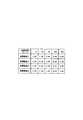
そして、高温高湿試験として60℃で湿度90%の高温高湿槽内に放置し、発光面積の比率の経時変化の平均値を調べたところ、図2に示す結果が得られた。アノード電極2とカソード電極との重なり面積(理論上の初期発光面積)を1.00としている。この図2から明らかなように、保護構造2、4が放置時間456時間で0.99と一番良いことが分かるが、他の保護構造1、3とあまり差は無い。なお、比較例として無機保護膜5、シランカップリング層6および有機保護膜7を一切設けずに上記基本構造を対向基板11のみで封止した構造では、456時間で0.87となっており、これらの部材がダークスポットの発生、成長に抑止力があることが観察された。
【0021】
また、高温試験として温度80℃の高温槽内に放置し、アノード−カソード電極間ショートに対する生存率の経時変化の平均値を調べたところ、図3に示す結果が得られた。この図3から明らかなように、保護構造1の場合放置時間456時間で40.0と一番悪く、保護構造2の場合も放置時間456時間で83.3とかなり悪く、これに対し、保護構造3、4の場合には放置時間456時間で100.0と少しも減少せずかなり良いことが分かる。以上のことから、保護構造3、4の場合には、対向基板11を透明基板1の基本構造に貼り合わせる時に有機EL層3にかかる物理応力や対向基板11の重さによる物理応力の負荷を軽減することができるため、ダークスポットの発生、成長が抑制され、電極間ショートが生じにくいということが分かる。
【0022】
ところで、保護構造3、4(各発光箇所数は5個)について、JIS5400に準拠した碁盤目テープ法(密着強度)試験法を行ったところ、保護構造3の場合のJIS評価点の平均値が1.2点とかなり低かったのに対し、保護構造4の場合のJIS評価点の平均値は8.8点とかなり高かった。これは、保護構造3の場合には、シランカップリング層6を有していないので、有機保護膜7と無機保護膜5との密着性があまり良くなく、これに対し、保護構造4の場合には、シランカップリング層6を有しているので、有機保護膜7と無機保護膜5との実質的な密着性が良くなることに起因するものと思われる。したがって、この密着強度の点を考慮すると、保護構造3よりも保護構造4の方が好ましい。
【0023】
【発明の効果】
以上説明したように、請求項1に記載の発明によれば、第1電極、有機EL層および第2電極を無機保護膜および樹脂封止膜で覆っているので、外部からの酸素、水の浸入を防ぐことができ、ひいてはダークスポットの発生、成長を抑制することができる。また、無機保護膜の表面をシランカップリング層を介して有機保護膜で覆っているので、樹脂封止膜が硬化する際に副生成物を発生しても、この副生成物が無機保護膜のピンポール欠陥を通して無機保護膜下に浸入しないようにすることができ、ひいてはダークスポットの発生、成長をより一層抑制することができる。また、有機保護膜の膜厚をダークスポットの発生核となり得る欠陥や異物をステップカバレージすることができる膜厚とすれば、ダークスポットの発生、成長をさらに抑制することができる。さらに、樹脂封止膜が硬化したときの残留応力を有機保護膜で緩和することができ、ひいては両電極がショートしないようにすることができる。
【図面の簡単な説明】
【図1】この発明の一実施形態における電界発光素子の断面図。
【図2】発光面積の比率の経時変化を説明するために示す図。
【図3】電極間ショートに対する生存率の経時変化を説明するために示す図。
【符号の説明】
1 透明基板
2 アノード電極
3 有機EL層
4 カソード電極
5 無機保護膜
6 シランカップリング層
7 有機保護膜
11 対向基板
12 樹脂封止膜[0001]
BACKGROUND OF THE INVENTION
The present invention relates to an electroluminescent element provided with an organic EL (electroluminescence) layer.
[0002]
[Prior art]
An electroluminescent device provided with an organic EL layer has attracted attention as a device that realizes a direct current low-voltage driving device because it is self-luminous and has a wide viewing angle and is a solid device, has excellent impact resistance. However, in the electroluminescent device provided with such an organic EL layer, the long-term storage reliability (life) is longer than that of an inorganic thin film device (organic dispersion type inorganic EL device) such as a ZnS: Mn inorganic thin film device. There were problems that hindered practical use such as lacking.
[0003]
However, in recent years, the light emission efficiency has been improved by developing a two-layer structure (hole transport layer and light-emitting layer) and doping the light-emitting layer with a laser dye, and the half-life when driving the device has exceeded 10,000 hours. Has been made. However, the measurement of the half-life of such an electroluminescent device is mostly measured in a nitrogen atmosphere, an inert gas atmosphere, or a room temperature environment under vacuum, and lacks reliability in actual use. It has been pointed out. One of the major problems in such an electroluminescent device is the generation and growth of dark spots that are non-light emitting regions.
[0004]
[Problems to be solved by the invention]
Therefore, recently, one side of the transparent substrate having an anode electrode, an organic EL layer, and a cathode electrode provided in this order on one surface is entirely covered with a resin sealing film made of an ultraviolet curable epoxy resin. It has been considered that the covering prevents the entry of oxygen and water from the outside and suppresses the generation and growth of dark spots. However, when the ultraviolet curable epoxy resin is cured, if it is performed in a vacuum to eliminate bubbles, the epoxy resin contracts greatly, and the organic EL layer is crushed and both electrodes are short-circuited. Sometimes. In addition, when the ultraviolet curable epoxy resin that covers the entire surface of one surface of the transparent substrate is cured, Lewis acids, Bronsett acids, etc. are generated over a wide range as by-products, and dark spots are not generated. This may cause growth or cause corrosion of the electrode. The present invention can suppress the generation and growth of dark spots and prevent short-circuiting between both electrodes.
[0005]
[Means for Solving the Problems]
According to the first aspect of the present invention, the first electrode (anode electrode), the organic EL layer, and the second electrode (cathode electrode) are provided in this order on one surface, and the first electrode and the organic EL layer A counter substrate on one surface side of the substrate provided with an inorganic protective film, a silane coupling layer and an organic protective film in this order so as to cover the second electrode, and thecounter substrate, the organic protective film, A resin sealing film is provided so as to cover the organic protective film, theinorganic protective film is madeof CeO2dispersed inSiO2, and theorganic protective film is made of polyparaxylene. The resin sealing film has a film thickness of 1 μm to 5 μm, and is made of an epoxy resin . According to the present invention, since the first electrode, the organic EL layer, and the second electrode are covered with the inorganic protective film and the resin sealing film, it is possible to prevent the intrusion of oxygen and water from the outside, and thus the dark spot. Generation and growth can be suppressed. Further, since the surface of the inorganic protective film is covered with the organic protective film through the silane coupling layer, even if a by-product is generated when the resin sealing film is cured, the by-product is not removed. Therefore, it is possible to prevent the penetration of the inorganic material under the inorganic protective film through the pin-pole defect, and the generation and growth of dark spots can be further suppressed. Further, if the thickness of the organic protective film is set to a thickness that can step-cover defects and foreign matters that can be dark spot nuclei, the generation and growth of dark spots can be further suppressed. Furthermore, the residual stress when the resin sealing film is cured can be relaxed by the organic protective film, so that both electrodes can be prevented from short-circuiting.
[0006]
DETAILED DESCRIPTION OF THE INVENTION
FIG. 1 shows a cross-sectional view of an electroluminescent element according to an embodiment of the present invention. The electroluminescent element includes a
[0007]
A plurality of
[0008]
An
[0009]
The material of the hole transport layer is a carbazole polymer, PPV (phenylene vinylene polymer), PPV derivative, PPV copolymer, polymer dispersion containing PEDOT (polyethylenedioxythiophene), 3-alkylthiophene polymer, and the like. . The material of the electron transport layer is an electron transport metal complex compound, preferably Alq3, Znq2, Bebq2, Zn-BTZ, a perylene derivative, or the like. Where q is 8-hydroxyquinoline, bq is 10-hydroxybenzoquinoline, and BTZ is 2- (o-hydroxyphenyl) benzothiazole.
[0010]
The hole transport layer is formed by dissolving the material in a solvent and performing coating (wet film formation), and the film thickness is 100 to 10,000 mm, preferably 300 to 2000 mm. The electron transport layer is formed by vapor deposition or coating, and the film thickness is 100 to 10,000 mm, preferably 300 to 2000 mm. When the electron transport layer is formed by coating, a solvent that dissolves 0.001 wt% or more at room temperature, for example, an aromatic hydrocarbon such as toluene or xylene, or a chlorine-based solvent such as dichloroethane is used.
[0011]
A plurality of cathode electrodes 4 are provided on the upper surface of the
[0012]
An inorganic
[0013]
A
[0014]
Then, in the chamber of the CVD apparatus, a
[0015]
On the other hand, the
[0016]
In the electroluminescent element configured as described above, the
[0017]
Next, a specific example will be described. First, an
[0018]
Then, an inorganic
[0019]
Further, an inorganic
[0020]
Then, as a high temperature and high humidity test, the sample was left in a high temperature and high humidity bath at 60 ° C. and a humidity of 90%, and the average value of the change over time in the ratio of the light emitting area was examined. The result shown in FIG. The overlapping area (theoretical initial light emitting area) between the
[0021]
Further, as a high-temperature test, the sample was left in a high-temperature bath at a temperature of 80 ° C., and the average value of the change over time of the survival rate with respect to the short between the anode and the cathode electrode was examined. The result shown in FIG. As is clear from FIG. 3, in the case of the
[0022]
By the way, when the cross-cut tape method (adhesion strength) test method based on JIS5400 was performed on the
[0023]
【The invention's effect】
As described above, according to the invention described in
[Brief description of the drawings]
FIG. 1 is a cross-sectional view of an electroluminescent element according to an embodiment of the present invention.
FIG. 2 is a diagram for explaining a change with time of a ratio of a light emitting area.
FIG. 3 is a view for explaining the change over time in the survival rate with respect to a short-circuit between electrodes.
[Explanation of symbols]
DESCRIPTION OF
Claims (2)
Translated fromJapanesePriority Applications (1)
| Application Number | Priority Date | Filing Date | Title |
|---|---|---|---|
| JP2000159372AJP4324718B2 (en) | 2000-05-30 | 2000-05-30 | Electroluminescent device |
Applications Claiming Priority (1)
| Application Number | Priority Date | Filing Date | Title |
|---|---|---|---|
| JP2000159372AJP4324718B2 (en) | 2000-05-30 | 2000-05-30 | Electroluminescent device |
Publications (2)
| Publication Number | Publication Date |
|---|---|
| JP2001338754A JP2001338754A (en) | 2001-12-07 |
| JP4324718B2true JP4324718B2 (en) | 2009-09-02 |
Family
ID=18663707
Family Applications (1)
| Application Number | Title | Priority Date | Filing Date |
|---|---|---|---|
| JP2000159372AExpired - LifetimeJP4324718B2 (en) | 2000-05-30 | 2000-05-30 | Electroluminescent device |
Country Status (1)
| Country | Link |
|---|---|
| JP (1) | JP4324718B2 (en) |
Cited By (2)
| Publication number | Priority date | Publication date | Assignee | Title |
|---|---|---|---|---|
| CN108832023A (en)* | 2018-06-29 | 2018-11-16 | 京东方科技集团股份有限公司 | Packaging structure, electronic device and packaging method |
| CN109037479A (en)* | 2018-07-27 | 2018-12-18 | 京东方科技集团股份有限公司 | Packaging method and display panel |
Families Citing this family (34)
| Publication number | Priority date | Publication date | Assignee | Title |
|---|---|---|---|---|
| JP3865056B2 (en) | 2002-01-22 | 2007-01-10 | セイコーエプソン株式会社 | Manufacturing method of sealing substrate |
| JP2003282242A (en)* | 2002-03-25 | 2003-10-03 | Toyota Central Res & Dev Lab Inc | Organic electroluminescent element and organic electronic device |
| JP3501148B2 (en)* | 2002-03-25 | 2004-03-02 | 富士電機ホールディングス株式会社 | Organic EL display |
| DE10222958B4 (en)* | 2002-04-15 | 2007-08-16 | Schott Ag | Process for producing an organic electro-optical element and organic electro-optical element |
| JP3729262B2 (en) | 2002-08-29 | 2005-12-21 | セイコーエプソン株式会社 | ELECTROLUMINESCENT DEVICE AND ELECTRONIC DEVICE |
| TWI272866B (en)* | 2002-10-16 | 2007-02-01 | Idemitsu Kosan Co | Organic electroluminescent display and method for manufacturing same |
| JP3997888B2 (en)* | 2002-10-25 | 2007-10-24 | セイコーエプソン株式会社 | Electro-optical device, method of manufacturing electro-optical device, and electronic apparatus |
| KR20040039608A (en)* | 2002-11-04 | 2004-05-12 | 주식회사 엘리아테크 | Apparatus and Method for manufacturing an Organic Electro Luminescence Display Device |
| US7728516B2 (en) | 2003-06-13 | 2010-06-01 | Fuji Electric Holdings Co., Ltd. | Organic EL display |
| GB2417599B (en)* | 2003-06-13 | 2006-10-04 | Fuji Electric Holdings Co | Organic el display |
| KR100540179B1 (en) | 2003-08-28 | 2006-01-10 | 한국과학기술연구원 | Inorganic thin layer and electroluminescence device comprising the same |
| JP5124083B2 (en)* | 2004-06-09 | 2013-01-23 | 三星ディスプレイ株式會社 | Organic electroluminescent display device and manufacturing method thereof |
| JP2005353577A (en)* | 2004-06-10 | 2005-12-22 | Samsung Sdi Co Ltd | Organic electroluminescent display device and manufacturing method thereof |
| JP4706394B2 (en)* | 2005-08-29 | 2011-06-22 | 株式会社豊田自動織機 | Method for manufacturing organic electroluminescence element |
| JP2009037799A (en)* | 2007-07-31 | 2009-02-19 | Sumitomo Chemical Co Ltd | LIGHT EMITTING ELEMENT AND MANUFACTURING METHOD THEREOF |
| JP5416913B2 (en)* | 2008-03-31 | 2014-02-12 | ローム株式会社 | Organic EL device |
| JP5543497B2 (en)* | 2009-03-04 | 2014-07-09 | エスアールアイ インターナショナル | Encapsulation method for organic electrical devices |
| WO2010106638A1 (en)* | 2009-03-17 | 2010-09-23 | パイオニア株式会社 | Method for manufacturing organic el panel and organic el panel |
| WO2011004567A1 (en)* | 2009-07-07 | 2011-01-13 | パナソニック株式会社 | Organic electroluminescent display device and manufacturing method therefor |
| FR2958795B1 (en)* | 2010-04-12 | 2012-06-15 | Commissariat Energie Atomique | ORGANIC OPTOELECTRONIC DEVICE AND METHOD OF ENCAPSULATION |
| JP5674707B2 (en)* | 2012-05-22 | 2015-02-25 | 株式会社東芝 | Display device |
| CN104064683A (en)* | 2013-03-21 | 2014-09-24 | 海洋王照明科技股份有限公司 | Organic electroluminescent device |
| KR20150011231A (en) | 2013-07-22 | 2015-01-30 | 삼성디스플레이 주식회사 | Organic light emitting display apparatus and the manufacturing method thereof |
| JP6266974B2 (en) | 2013-12-24 | 2018-01-24 | 株式会社ジャパンディスプレイ | Organic EL display device and manufacturing method thereof |
| CN105118933B (en)* | 2015-09-02 | 2018-03-13 | 深圳市华星光电技术有限公司 | Film encapsulation method and organic light emitting apparatus |
| CN106711354A (en) | 2016-12-02 | 2017-05-24 | 武汉华星光电技术有限公司 | Packaging method for organic semiconductor device |
| CN110226361A (en)* | 2017-01-26 | 2019-09-10 | 夏普株式会社 | Oled panel, the manufacturing method of oled panel, the manufacturing device of oled panel |
| JP6345905B1 (en)* | 2017-11-29 | 2018-06-20 | 堺ディスプレイプロダクト株式会社 | Manufacturing method of organic EL display device |
| US10637003B2 (en) | 2017-11-29 | 2020-04-28 | Sakai Display Products Corporation | Organic electroluminescent display device and method for producing same |
| JP6560401B2 (en)* | 2018-05-24 | 2019-08-14 | 堺ディスプレイプロダクト株式会社 | Organic EL display device |
| JP6608007B2 (en)* | 2018-07-17 | 2019-11-20 | 堺ディスプレイプロダクト株式会社 | Organic EL display device and manufacturing method thereof |
| CN109309176B (en)* | 2018-08-30 | 2020-09-01 | 武汉华星光电半导体显示技术有限公司 | Preparation method of display substrate and display substrate |
| CN110943182A (en) | 2019-11-22 | 2020-03-31 | 武汉华星光电半导体显示技术有限公司 | Organic electroluminescent device |
| CN113764598A (en)* | 2020-06-03 | 2021-12-07 | 咸阳彩虹光电科技有限公司 | Thin film packaging structure, OLED display panel and display |
- 2000
- 2000-05-30JPJP2000159372Apatent/JP4324718B2/ennot_activeExpired - Lifetime
Cited By (4)
| Publication number | Priority date | Publication date | Assignee | Title |
|---|---|---|---|---|
| CN108832023A (en)* | 2018-06-29 | 2018-11-16 | 京东方科技集团股份有限公司 | Packaging structure, electronic device and packaging method |
| US11239444B2 (en) | 2018-06-29 | 2022-02-01 | Boe Technology Group Co., Ltd. | Display panel, display apparatus, method of fabricating display panel, and encapsulating structure |
| CN109037479A (en)* | 2018-07-27 | 2018-12-18 | 京东方科技集团股份有限公司 | Packaging method and display panel |
| CN109037479B (en)* | 2018-07-27 | 2021-01-15 | 京东方科技集团股份有限公司 | Packaging method and display panel |
Also Published As
| Publication number | Publication date |
|---|---|
| JP2001338754A (en) | 2001-12-07 |
Similar Documents
| Publication | Publication Date | Title |
|---|---|---|
| JP4324718B2 (en) | Electroluminescent device | |
| US6707248B1 (en) | Opto-electrical devices | |
| JP6001595B2 (en) | Organic electroluminescence device | |
| US5952778A (en) | Encapsulated organic light emitting device | |
| JP4487010B2 (en) | Manufacturing method of organic light emitting device | |
| CN1150639C (en) | organic light emitting device | |
| US20050012448A1 (en) | Organic light emitting diode (oled) | |
| CN1841812A (en) | Organic electroluminescence element | |
| JP5266532B2 (en) | Light emitting element | |
| JP5124083B2 (en) | Organic electroluminescent display device and manufacturing method thereof | |
| JP3691192B2 (en) | Organic electroluminescence device | |
| JP4752087B2 (en) | Electroluminescent device | |
| JP3533790B2 (en) | Organic thin film light emitting device | |
| WO2005053053A1 (en) | Light-emitting device comprising an etch-protective layer | |
| CN100411186C (en) | Organic Light Emitting Display Panel | |
| KR101011718B1 (en) | Organic light emitting device and manufacturing method thereof | |
| JP2001185348A (en) | Photoelectric conversion element and method for manufacturing the same | |
| KR100595167B1 (en) | Organic electroluminescent device having an organic coating film for preventing moisture penetration | |
| JP2003297554A (en) | Light emitting element, display device using the same, and lighting device | |
| JPH11135258A (en) | Method for manufacturing electroluminescent device | |
| JP2001052857A (en) | Organic electroluminescence device and method of manufacturing the same | |
| JP2004152512A (en) | Organic electroluminescent display device and its manufacturing method | |
| US20100167440A1 (en) | Light Emissive Device | |
| JP3533776B2 (en) | Organic thin film light emitting device | |
| JPH05290976A (en) | Organic thin film electroluminescent element |
Legal Events
| Date | Code | Title | Description |
|---|---|---|---|
| A621 | Written request for application examination | Free format text:JAPANESE INTERMEDIATE CODE: A621 Effective date:20051228 | |
| RD02 | Notification of acceptance of power of attorney | Free format text:JAPANESE INTERMEDIATE CODE: A7422 Effective date:20060203 | |
| RD04 | Notification of resignation of power of attorney | Free format text:JAPANESE INTERMEDIATE CODE: A7424 Effective date:20060413 | |
| RD04 | Notification of resignation of power of attorney | Free format text:JAPANESE INTERMEDIATE CODE: A7424 Effective date:20080519 | |
| A977 | Report on retrieval | Free format text:JAPANESE INTERMEDIATE CODE: A971007 Effective date:20081117 | |
| A131 | Notification of reasons for refusal | Free format text:JAPANESE INTERMEDIATE CODE: A131 Effective date:20081125 | |
| A521 | Request for written amendment filed | Free format text:JAPANESE INTERMEDIATE CODE: A523 Effective date:20090123 | |
| TRDD | Decision of grant or rejection written | ||
| A01 | Written decision to grant a patent or to grant a registration (utility model) | Free format text:JAPANESE INTERMEDIATE CODE: A01 Effective date:20090512 | |
| A01 | Written decision to grant a patent or to grant a registration (utility model) | Free format text:JAPANESE INTERMEDIATE CODE: A01 | |
| A61 | First payment of annual fees (during grant procedure) | Free format text:JAPANESE INTERMEDIATE CODE: A61 Effective date:20090525 | |
| FPAY | Renewal fee payment (event date is renewal date of database) | Free format text:PAYMENT UNTIL: 20120619 Year of fee payment:3 | |
| R150 | Certificate of patent or registration of utility model | Ref document number:4324718 Country of ref document:JP Free format text:JAPANESE INTERMEDIATE CODE: R150 Free format text:JAPANESE INTERMEDIATE CODE: R150 | |
| FPAY | Renewal fee payment (event date is renewal date of database) | Free format text:PAYMENT UNTIL: 20120619 Year of fee payment:3 | |
| FPAY | Renewal fee payment (event date is renewal date of database) | Free format text:PAYMENT UNTIL: 20130619 Year of fee payment:4 | |
| S111 | Request for change of ownership or part of ownership | Free format text:JAPANESE INTERMEDIATE CODE: R313113 | |
| R350 | Written notification of registration of transfer | Free format text:JAPANESE INTERMEDIATE CODE: R350 | |
| R250 | Receipt of annual fees | Free format text:JAPANESE INTERMEDIATE CODE: R250 | |
| R250 | Receipt of annual fees | Free format text:JAPANESE INTERMEDIATE CODE: R250 | |
| R250 | Receipt of annual fees | Free format text:JAPANESE INTERMEDIATE CODE: R250 | |
| EXPY | Cancellation because of completion of term |