JP4324170B2 - Imaging apparatus and display control method - Google Patents
Imaging apparatus and display control methodDownload PDFInfo
- Publication number
- JP4324170B2 JP4324170B2JP2006015096AJP2006015096AJP4324170B2JP 4324170 B2JP4324170 B2JP 4324170B2JP 2006015096 AJP2006015096 AJP 2006015096AJP 2006015096 AJP2006015096 AJP 2006015096AJP 4324170 B2JP4324170 B2JP 4324170B2
- Authority
- JP
- Japan
- Prior art keywords
- feature value
- subject
- image
- image data
- feature
- Prior art date
- Legal status (The legal status is an assumption and is not a legal conclusion. Google has not performed a legal analysis and makes no representation as to the accuracy of the status listed.)
- Expired - Fee Related
Links
Images


Classifications
- G—PHYSICS
- G03—PHOTOGRAPHY; CINEMATOGRAPHY; ANALOGOUS TECHNIQUES USING WAVES OTHER THAN OPTICAL WAVES; ELECTROGRAPHY; HOLOGRAPHY
- G03B—APPARATUS OR ARRANGEMENTS FOR TAKING PHOTOGRAPHS OR FOR PROJECTING OR VIEWING THEM; APPARATUS OR ARRANGEMENTS EMPLOYING ANALOGOUS TECHNIQUES USING WAVES OTHER THAN OPTICAL WAVES; ACCESSORIES THEREFOR
- G03B13/00—Viewfinders; Focusing aids for cameras; Means for focusing for cameras; Autofocus systems for cameras
- G03B13/18—Focusing aids
- G03B13/30—Focusing aids indicating depth of field
- H—ELECTRICITY
- H04—ELECTRIC COMMUNICATION TECHNIQUE
- H04N—PICTORIAL COMMUNICATION, e.g. TELEVISION
- H04N23/00—Cameras or camera modules comprising electronic image sensors; Control thereof
- H04N23/60—Control of cameras or camera modules
- H04N23/61—Control of cameras or camera modules based on recognised objects
- H—ELECTRICITY
- H04—ELECTRIC COMMUNICATION TECHNIQUE
- H04N—PICTORIAL COMMUNICATION, e.g. TELEVISION
- H04N23/00—Cameras or camera modules comprising electronic image sensors; Control thereof
- H04N23/60—Control of cameras or camera modules
- H04N23/63—Control of cameras or camera modules by using electronic viewfinders
- H04N23/633—Control of cameras or camera modules by using electronic viewfinders for displaying additional information relating to control or operation of the camera
- H04N23/635—Region indicators; Field of view indicators
- H—ELECTRICITY
- H04—ELECTRIC COMMUNICATION TECHNIQUE
- H04N—PICTORIAL COMMUNICATION, e.g. TELEVISION
- H04N23/00—Cameras or camera modules comprising electronic image sensors; Control thereof
- H04N23/60—Control of cameras or camera modules
- H04N23/67—Focus control based on electronic image sensor signals
- H04N23/675—Focus control based on electronic image sensor signals comprising setting of focusing regions
- H—ELECTRICITY
- H04—ELECTRIC COMMUNICATION TECHNIQUE
- H04N—PICTORIAL COMMUNICATION, e.g. TELEVISION
- H04N2101/00—Still video cameras
Landscapes
- Engineering & Computer Science (AREA)
- Multimedia (AREA)
- Signal Processing (AREA)
- Physics & Mathematics (AREA)
- General Physics & Mathematics (AREA)
- Studio Devices (AREA)
Description
Translated fromJapanese本発明は撮像装置、および、撮像装置の制御方法に関するものである。The present invention relates to an imaging device and a method for controlling theimaging device .
撮像した画像データの中から被写体の顔の特徴的な部位を検出したり、肌色部分を検出することで、顔領域を自動で検出する顔検出技術を用いて、入力された画像から顔画像を抽出する技術がある。特開2004−013871号公報には、特定の画像データを参照画像として登録し、新たに入力された画像データが参照画像に合致するかを判断する技術が提案されている。 Using face detection technology that automatically detects the face area by detecting the characteristic part of the subject's face from the captured image data and detecting the skin color part, the face image is extracted from the input image. There is technology to extract. Japanese Patent Laid-Open No. 2004-013871 proposes a technique for registering specific image data as a reference image and determining whether newly input image data matches the reference image.
例えば、特開平09−251534号公報では、予め登録された顔の画像データを識別対象となる画像データとの相関値を計算することで、顔が存在する領域を特定する方法が開示されている。また、特開平10−162118号公報では、画像データを周波数帯域別に複数に分割して顔が存在する可能性が高いと推定される領域を限定し、限定した領域に対して予め登録された顔画像データとの相関値を計算する方法が開示されている。 For example, Japanese Patent Application Laid-Open No. 09-251534 discloses a method of specifying a region where a face exists by calculating a correlation value between image data of a face registered in advance and image data to be identified. . In Japanese Patent Laid-Open No. 10-162118, image data is divided into a plurality of frequency bands to limit a region where it is estimated that a face is likely to exist, and a face registered in advance for the limited region. A method for calculating a correlation value with image data is disclosed.
これらの技術をカメラに応用した例を説明する。
特開2003−107335号公報では、画像データから形状解析等の手法によって主被写体を自動的に検出し、検出された主被写体に対して焦点検出エリアを表示する。そして、この焦点検出エリアに対して焦点調節処理を行わせる方法が開示されている。特開2004−317699号公報では、画像データから特徴点を抽出することで主被写体である顔の存在する領域を識別し、この領域の大きさに応じて焦点検出エリアを設定する方法が開示されている。また、特開2004−320286号公報では、画像データから特徴点を抽出することで顔の存在する領域を識別し、この領域の大きさに応じてズーム駆動を行う方法が開示されている。
In Japanese Patent Laid-Open No. 2003-107335, a main subject is automatically detected from image data by a technique such as shape analysis, and a focus detection area is displayed for the detected main subject. And the method of performing a focus adjustment process with respect to this focus detection area is disclosed. Japanese Patent Application Laid-Open No. 2004-317699 discloses a method of identifying a region where a face as a main subject exists by extracting feature points from image data and setting a focus detection area according to the size of this region. ing. Japanese Patent Application Laid-Open No. 2004-320286 discloses a method of identifying a region where a face exists by extracting feature points from image data and performing zoom driving according to the size of the region.
ところで、スポーツをしている被写体はその動きが激しいため、撮影したい特定の選手を光学ファインダーを用いて、あるいは、撮像装置の背面モニターを用いて発見することは難しかった。 By the way, since a sporting subject moves rapidly, it has been difficult to find a specific player who wants to shoot using an optical viewfinder or a rear monitor of an imaging device.
また、カメラマンとしてパーティーや遠足といった行事に参加した場合には、参加者を偏り無く撮るように要求されることになる。しかしながらこのような行事には不特定多数の人物が参加することも多く、カメラマンが全ての参加者について撮影が済んだかを確認することは大変な労力を有する。上記の文献に開示された技術を用いれば、予め行事の参加者の顔の画像データを参照画像として登録し、撮影された画像データと比較することで、撮影が済んでいない参加者を検索することができる。また、誰を何枚撮影したかを調べることもできる。しかし、この方法では、事前に参加者の画像データを参照画像として登録をする手順が必要となり、手間を要する。また、急な撮影の依頼であり、参加者の画像データを参照画像として登録することができない場合には、この方法を用いることはできない。 In addition, when participating in events such as parties and excursions as a photographer, it is required that the participants be photographed without bias. However, in many cases, an unspecified number of persons participate in such events, and it is very difficult for the photographer to check whether all the participants have been photographed. If the technique disclosed in the above document is used, the image data of the face of the participant of the event is registered in advance as a reference image, and the participant who has not been photographed is searched by comparing the image data with the photographed image data. be able to. You can also check who has taken how many photos. However, this method requires a procedure for registering the participant's image data as a reference image in advance, which is troublesome. In addition, this method cannot be used when there is a sudden request for shooting and the image data of the participant cannot be registered as a reference image.
そこで、本発明は、被写体検出技術を用いて、被写体を自動で抽出し、記憶されたデータとの比較結果に基づきディスプレイに情報を表示することで、ユーザーの撮影の負担を減らすことを課題としている。 Therefore, the present invention has an object to reduce a user's shooting burden by automatically extracting a subject using subject detection technology and displaying information on a display based on a comparison result with stored data. Yes.
上記課題を解決するため、本願に係る撮像装置は、撮像素子と、前記撮像素子の出力から生成された画像データから、検出対象となる被写体を検出し、検出した被写体の特徴を示す特徴値を演算する検出回路と、前記検出回路にて演算された特徴値を記憶する記憶回路と、前記検出回路にて得られた特徴値と、前記記憶回路に記憶されている特徴値を比較し、これらの特徴値が同一の被写体に対する特徴値であるかを判定する比較回路と、前記撮像素子の出力から生成される画像データを用いて、動画表示を行うディスプレイと、撮影を指示するための操作部材とを備え、前記記憶回路は、前記記憶した特徴値に対応する被写体の静止画の撮影回数、および、動画の撮影時間の少なくとも一方に関する情報を記憶し、前記記録回路は、前記比較回路によって、前記操作部材が操作されることに応じて得られた画像データから演算した特徴値と前記記憶回路に記憶された特徴値が同一の被写体に対する特徴値でないと判定された場合には、前記操作部材が操作されることに応じて得られた画像データから演算した特徴値を新たな被写体の特徴値として記憶し、同一の被写体に対する特徴値であると判定された場合には、前記同一の被写体と判定された特徴値に対応する被写体の前記静止画の撮影回数、および、動画の撮影時間の少なくとも一方を更新し、前記ディスプレイは、前記比較回路によって、前記操作部材が操作されることによらずに前記ディスプレイに表示された動画に用いられる画像データから前記検出回路が演算した特徴値と前記記憶回路に記憶された特徴値が同一の被写体に対する特徴値であると判定された場合には、前記同一の被写体と判定された特徴値に対応する被写体の前記静止画の撮影回数、および、動画の撮影時間の少なくとも一方に関する情報を前記動画に表示することを特徴とするものである。To solve the above problem, an imaging apparatus according to the present application, an imaging element, the image data generated from the output ofthe image sensor, and detects an object to be detected, a feature value indicating a feature of the detected objectcomparing a detection circuit for calculating a storage circuit for storing the calculated feature values by the detecting circuit, a feature value obtained by the detecting circuit, the characteristic value stored in the storagecircuit, these a comparisoncircuit feature value to determine whether the feature values for the same subject, by using the image data generated from the output ofthe image pickup device, a display for movie display,operation member for instructing shooting And the storage circuit stores information on at least one of the number of still image shootings of the subject corresponding to the stored feature value and the shooting time of the moving image, and the recording circuit stores the ratio. When it is determined by the circuit that the feature value calculated from the image data obtained in response to the operation member being operated and the feature value stored in the storage circuit are not feature values for the same subject, A feature value calculated from image data obtained in response to operation of the operation member is stored as a feature value of a new subject, and when it is determined that the feature value is for the same subject, the same value is used. At least one of the number of still image shootings of the subject corresponding to the feature value determined to be the subject and the shooting time of the moving image is updated, and the operation member is operated by the comparison circuit in the display The feature value calculated by the detection circuit from the image data used for the moving image displayed on the display is the same as the feature value stored in the storage circuit. When it is determined that the feature value is for a subject, information on at least one of the number of still image shootings of the subject corresponding to the feature value determined to be the same subject and the shooting time of the moving image is It is characterized by being displayed on amoving image .
同様に上記課題を解決するため、本願に係る撮像装置の制御方法は、撮像素子の出力から生成された画像データから、検出対象となる被写体を検出し、検出した被写体の特徴を示す特徴値を演算する検出工程と、前記検出工程にて演算された特徴値を記憶手段に記憶する第1の記憶工程と、前記検出工程にて得られた特徴値と、前記第1の記憶工程にて記憶した特徴値を比較し、これらの特徴値が同一の被写体に対する特徴値であるかを判定する比較工程と、前記記憶した特徴値に対応する被写体が検出された静止画の撮影回数、および、動画の撮影時間の少なくとも一方に関する情報を前記記憶手段に記憶する第2の記憶工程と、前記撮像素子の出力から生成された画像データを用いて、ディスプレイに動画表示を行う表示工程と、を備え、前記比較工程において、撮影を指示するための操作部材が操作されることに応じて得られた画像データから演算された特徴値と前記記憶回路に記憶された特徴値が同一の被写体に対する特徴値でないと判定した場合には、前記第1の記憶工程において、前記検出回路が演算した特徴値を新たな被写体の特徴値として記憶し、前記比較工程において、前記操作部材が操作されることに応じて得られた画像データから演算された特徴値と前記記憶回路に記憶された特徴値が同一の被写体に対する特徴値であると判定した場合には、前記第2の記憶工程において、前記同一の被写体と判定された特徴値に対応する被写体の前記静止画の撮影回数、および、動画の撮影時間の少なくとも一方を更新し、前記比較工程において、前記操作部材が操作されることによらずに前記ディスプレイに表示された動画に用いられる画像データから演算された特徴値と前記記憶回路に記憶された特徴値が同一の被写体に対する特徴値であると判定した場合には、前記表示工程において、前記同一の被写体と判定された特徴値に対応する被写体の前記静止画の撮影回数、および、動画の撮影時間の少なくとも一方に関する情報を前記記憶手段から読み出して前記動画に表示することを特徴とするものである。Similarly, in order to solve the above-described problem, the control method of theimaging apparatus according to the present application detects a subject to be detected from image data generated from the output of the imaging device, and obtains a feature value indicating a feature of the detected subject. A detection step for calculating, afirst storage step for storing the feature value calculated in the detection step in a storage means, a feature value obtained in the detection step, anda storage in the first storage stepcomparingthe featurevalues, a comparison stepin which these feature values to determine whether the feature values for the same subject,the number of times of photographing the still image object has been detected corresponding to the characteristic value the storage, and, moving comprisinga storage step second storing information regarding at least one of shooting time of said storage means byusing the image data generated from the output ofthe image sensor, and a display step for displaying a moving image display, theIn the comparison step, feature values stored in the feature value and the storage circuit to which an operating member is calculated from the image data obtained in response to being operated for instructing shooting is not characteristic values for the same subject In the first storage step, the feature value calculated by the detection circuit is stored as a new subject feature value, and the operation member is operated in the comparison step. When it is determined that the feature value calculated from the obtained image data and the feature value stored in the storage circuit are the feature values for the same subject, in the second storage step, the same subject At least one of the number of still image shootings of the subject corresponding to the determined feature value and the shooting time of the moving image is updated, and the operation member is operated in the comparison step. If it is determined that the feature value calculated from the image data used for the moving image displayed on the display and the feature value stored in the storage circuit are the feature values for the same subject, In the display step, information relating to at least one of the number of times of shooting the still image of the subject corresponding to the feature value determined to be the same subject and the shooting time of the moving image is read from the storage unit and displayed on the moving image. It is characterized by this.
本発明によれば、被写体検出技術を用いて、被写体を自動で抽出し、記憶されたデータとの比較結果に基づきディスプレイに情報を表示することで、ユーザーの撮影の負担を減らすことができる。 According to the present invention, a subject can be automatically extracted by using a subject detection technique, and information can be displayed on a display based on a comparison result with stored data, thereby reducing a user's shooting burden.
以下、図面を用いながら、本発明の好適な実施形態について説明を行う。 Hereinafter, preferred embodiments of the present invention will be described with reference to the drawings.
(第1の実施形態)
第1の実施形態における撮像装置100の構成を図1に示す。本実施形態では撮像装置として、電子スチルカメラを例にあげて説明を行う。(First embodiment)
FIG. 1 shows the configuration of the
図1において、101は被写体像を撮像素子102に結像するための対物レンズ群である。102は対物レンズ群101により結像された被写体像をアナログの画像データとして出力する光電変換機能を有するCCD等の撮像素子である。103は撮像素子102にて光電変換されたアナログの画像データをデジタルの画像データに変換するA/Dコンバータである。104はA/Dコンバータ103にてデジタルの画像データに変換された画像データに種々の画像処理を施し、表示用画像データや記録用画像データを生成する画像処理回路である。105は画像データを転送するためのデータバスである。106はディスプレイ108に画像を表示するための表示用画像データを加工する表示回路である。107は表示用画像データをアナログの画像データに変換して出力するD/Aコンバータである。108はD/Aコンバータ107にてアナログの画像データに変換した表示用画像データを表示するための液晶モニターからなるディスプレイである。109は撮像装置100の処理のプログラムや撮像処理に必要なデータを格納するフラッシュメモリ等のシステム記憶部である。110はシステム記憶部109にデータを転送するためのシステム記憶部コントローラである。111は撮影した画像データを記録する書き換え可能なメモリカードである。112はメモリカード111を着脱可能にするメモリソケットである。113は撮影された画像データを、メモリソケット112を介してメモリカード111に転送するためのメモリカードコントローラである。114は撮像装置100の各種プログラムを実行するCPUである。CPU114はシステム記憶部109に記憶されているプログラムに従って撮影処理を制御する。 In FIG. 1, reference numeral 101 denotes an objective lens group for forming a subject image on the
115は撮像装置100の各種スイッチ類の信号を制御するインターフェース部である、Input/Outputインターフェース部(これよりI/Oインターフェース部という)である。116は撮像装置100の処理モードをユーザーが指定するためのモードスイッチである。処理モードとしては、撮影を行うための撮影モード、撮影した画像をディスプレイ108にて見るための再生モード、および、検出対象となる被写体の特徴値を記憶させる登録モードがある。117はユーザーが撮像装置100に対する指示を入力するための十字キーからなる送りボタンである。118は静止画の撮影を指示するシャッターボタンである。このシャッターボタンをストロークの半分だけ押し込む(これより、半押しという)ことで不図示のスイッチSW1がオンし、ストロークの全てを押し込む(これより、全押しという)ことで不図示のスイッチSW2がオンする。119はディスプレイ108で画像を表示するために、表示回路106にデータバス105を介して、画像処理回路104から送られる表示用画像データを保持するためのDRAMである。120はDRAM119をデータバス105に接続するメモリコントローラである。
121はデータバス105を介して送られてくる表示用画像データと、パラメータ保持回路124から読み出したパラメータを用いて、検出対象となる被写体の特徴的な部分、例えば人の顔を画像データから検出することができる特徴検出回路である。特徴検出回路121は検出した特徴的な部分を特徴値として算出し、CPU114はこの特徴値を特徴値記憶回路122に転送して記憶させる。なお、過去の撮影によって生成した特徴値をメモリカード111またはシステム記憶部109に保存させておくことも可能である。CPU114はこれらメモリカード111またはシステム記憶部109に記憶された特徴値をデータバス105を介して読み出し、特徴値記憶回路122に記憶させる。123は特徴値を比較する特徴値比較回路であり、特徴検出回路121が出力する特徴値と特徴値記憶回路122から読み出した特徴値を比較し、一致の度合いを演算する。特徴値比較回路123は、この一致の度合いが高ければ、すなわち類似していれば特徴検出回路121によって検出された特徴値を有する被写体と、特徴値記憶回路122に記憶された特徴値を有する被写体とが同一であると判定する。 Reference numeral 121 detects the characteristic portion of the subject to be detected, for example, a human face from the image data, using the display image data sent via the
ここで、画像データから顔を検出する技術としては、様々な手法が公知となっている。例えば、ニューラルネットワークに代表される学習を用いた方法がある。また、目、鼻、口、および、顔の輪郭といった物理的な形状の特徴のある部位を画像データからテンプレートマッチングを用いて識別する手法がある。他にも、肌の色や目の形といった画像データの特徴量を検出し統計的解析を用いた手法があげられる(例えば、特開平10−232934号公報や特開2000−48184号公報等を参照)。さらに、直前の顔領域が検出された位置の近傍であるかを判定したり、服の色を加味するために顔領域の近傍の色を判定したり、あるいは、画面の中央付近ほど顔識別のための閾値を低く設定したりする方法がある。または予め主被写体が存在する領域を指定させてヒストグラムや色情報を記憶し、相関値を求めることで主被写体を追尾する方法がある。本実施形態では、一対の目(両目)、鼻、口、および、顔の輪郭を検出し、これらの相対位置より人の顔領域を決定する手法により顔領域の識別処理を行っている。 Here, various techniques are known as techniques for detecting a face from image data. For example, there is a method using learning represented by a neural network. In addition, there is a technique for identifying parts having physical shape features such as eyes, nose, mouth, and facial contour from image data using template matching. In addition, there is a technique that detects a feature amount of image data such as skin color or eye shape and uses statistical analysis (for example, Japanese Patent Laid-Open Nos. 10-232934 and 2000-48184). reference). In addition, it is determined whether the previous face area is near the detected position, the color near the face area is determined in consideration of the color of clothes, or the face identification is performed closer to the center of the screen. There is a method of setting the threshold value for this purpose low. Alternatively, there is a method of tracking the main subject by specifying a region in which the main subject exists in advance, storing a histogram and color information, and obtaining a correlation value. In the present embodiment, face area identification processing is performed by detecting a pair of eyes (both eyes), nose, mouth, and face outline, and determining a human face area from these relative positions.
また、特徴検出回路121はパラメータ保持回路124から読み出すデータに応じて、人の顔以外の対象(例えば、動物、選手の背番号、特定の車)を検出することも可能である。例えば、特開平5−89244号公報には、カメラで撮像した画像データ中のナンバープレートの文字を認識する方法が提案されている。例えばスポーツ選手のユニフォームの背番号を特徴値として予め記憶し、撮影した静止画から、上記の特徴と一致する部分を検索する。また、特開平07−231733号公報には、魚を写した画像データを用いて魚の全長と体高より魚の種別を認識する方法が提案されている。この技術は動物の検出にも応用できる。このように特徴検出回路121はパラメータ保持回路124から読み出すデータに応じて、任意の被写体を検出することができる。 The feature detection circuit 121 can also detect an object other than a human face (for example, an animal, a player's spine number, a specific car) in accordance with data read from the parameter holding circuit 124. For example, Japanese Patent Application Laid-Open No. 5-89244 proposes a method for recognizing license plate characters in image data captured by a camera. For example, a uniform number of a sports player is stored in advance as a feature value, and a portion that matches the above feature is searched from a photographed still image. Japanese Patent Application Laid-Open No. 07-231733 proposes a method for recognizing the type of fish from the total length and height of the fish using image data representing the fish. This technology can also be applied to animal detection. As described above, the feature detection circuit 121 can detect an arbitrary subject according to the data read from the parameter holding circuit 124.
125は撮影履歴スイッチである。本実施形態では、撮影履歴スイッチ125はユーザーによって操作され、撮影履歴スイッチがオンとなっている間を履歴期間として設定する。履歴期間以外では、特徴値比較回路123は、特徴検出回路121が出力する特徴値と特徴値記憶回路122から読み出した全ての特徴値を比較する。反対に履歴期間では、特徴値比較回路123は、特徴検出回路121が出力する特徴値と、履歴期間に新たに特徴値記憶回路122に記憶された特徴値を比較する。つまり、撮影履歴スイッチ125がオンされた場合は、特徴値比較回路123は、撮影履歴スイッチ125のオンによって設定された履歴期間よりも前に特徴値記憶回路122に記憶された特徴値を用いない。 Reference numeral 125 denotes a photographing history switch. In the present embodiment, the shooting history switch 125 is operated by the user, and the period during which the shooting history switch is on is set as the history period. Outside the history period, the feature
126は焦点調節回路であり、対物レンズ群101内のフォーカスレンズを駆動することで、撮像素子102に結像される被写体像の合焦状態を調節する。127は露出量調節回路であり、対物レンズ群101の間、あるいは、対物レンズ群101の隣に配置された絞りやシャッターを制御することで、撮像素子102に到達する光量を調節する。 A focus adjustment circuit 126 drives a focus lens in the objective lens group 101 to adjust a focus state of a subject image formed on the
この撮像装置100は、シャッターボタン118が全押しされてスイッチSW2がオンするよりも前の段階では、撮像素子102の周期的な出力を用いて表示用画像データを随時更新し、ディスプレイ108に被写体の動画像を表示するモニター処理を連続して行う。モニター処理では被写体の画像が連続して更新された動画像が表示されるので、ユーザーはディスプレイ108に表示された画像を見ながら、被写体の様子を観察し、撮影のタイミングを計ることができる。また、このモニター処理に並行して、特徴検出回路121による特徴検出処理が連続して行われる。本実施形態では特徴検出処理として人の顔を検出する顔検出処理を行うものであり、パラメータ保持回路124には人の顔の特徴を示す値をあらかじめ記録しておく。特徴検出回路121によって人の顔が検出され、ディスプレイ108は、人の顔が検出された位置に、そのことを示す枠を被写体の画像に重畳して表示する。 In the
撮像装置100は検出された顔の位置に対して、焦点調節を行うため、被写体が移動したり画角が変化したりしても、撮像装置100は人の顔の位置に焦点を合わせることができる。また、撮像装置100は検出された顔の位置の重み付けを最も大きくして、露出量を調節するので、画角が変化したり被写体が移動したりしても、撮像装置100は人の顔の輝度を適正化した画像データを得ることができる。 Since the
また、シャッターボタン118によって撮影のタイミングが指示されると、撮影直後に、撮影した画像がディスプレイ108に表示される。この処理により、ユーザーは撮影の成否を確認することができる。 Further, when the shooting timing is instructed by the
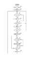
次に図2に示すフローチャートを用いて撮像装置100の撮影処理を説明する。
モードスイッチ116によって撮影モードが設定されると、図2に示すフローチャートが開始される。Next, photographing processing of the
When the shooting mode is set by the
ステップS101にて、CPU114は撮影履歴スイッチ125の状態の確認を行う。撮影履歴スイッチ125がオンされていれば履歴期間が設定されていると判定する。
ステップS102にて、CPU114は撮像素子102の出力を用いて表示用画像データを生成し、ディスプレイ108に被写体の画像を表示するモニター処理を開始させる。
ステップS103にて、撮像素子102が光電変換を行ってアナログの画像データを出力し、画像処理回路104がアナログの画像データから得られたデジタルの画像データを基に表示用画像データを生成し、DRAM119に記憶させる。そしてディスプレイ108がこの表示用画像データを用いて被写体の画像を表示する。In step S <b> 101, the CPU 114 confirms the state of the shooting history switch 125. If the photographing history switch 125 is turned on, it is determined that the history period is set.
In step S <b> 102, the CPU 114 generates display image data using the output of the
In step S103, the
ステップS104にて、特徴検出回路121がDRAM119に記憶された表示用画像データを読出し、パラメータ保持回路124から読み出したパラメータを用いて、顔検出処理を行い、特徴値を算出する。複数の顔が検出された場合には、それぞれの顔に対して特徴値を算出する。顔検出処理は、表示用画像データの基となるデジタルの画像データや、このデジタルの画像データから別に生成された検出用画像データから行っても構わない。 In step S104, the feature detection circuit 121 reads display image data stored in the DRAM 119, performs face detection processing using the parameters read from the parameter holding circuit 124, and calculates feature values. When a plurality of faces are detected, a feature value is calculated for each face. The face detection process may be performed from digital image data that is the basis of the display image data, or detection image data generated separately from the digital image data.
ステップS105にて、CPU114はステップS104での顔検出処理が成功したかを判定し、成功していればステップS106に進み、失敗していればステップS115に進む。 In step S105, the CPU 114 determines whether the face detection process in step S104 is successful. If it is successful, the process proceeds to step S106, and if it is unsuccessful, the process proceeds to step S115.
顔の検出処理が成功していれば、ステップS106にて、CPU114は撮影履歴スイッチ125がオンされているかを判定する。撮影履歴スイッチ125がオンされていればステップS107に進み、特徴値記憶回路122から履歴期間に記憶された特徴値として、後述する履歴フラグが設定された特徴値を読み出す。履歴フラグが設定された特徴値については、後述する。 If the face detection process is successful, in step S106, the CPU 114 determines whether the shooting history switch 125 is turned on. If the photographing history switch 125 is turned on, the process proceeds to step S107, and a feature value with a history flag set later is read from the feature
撮影履歴スイッチ125がオンされていなければステップS108に進み、特徴値記録回路122から全ての特徴値を読み出す。この特徴値にはメモリカード111またはシステム記憶部109から読み出した特徴値も含まれる。 If the photographing history switch 125 is not turned on, the process proceeds to step S108, and all feature values are read from the feature
ステップS109にて、特徴値比較回路123は、ステップS107あるいはステップS108で読み出した特徴値と、ステップS104にて得られた特徴値を比較する。そして比較した結果、これらの特徴値の類似度が基準となるレベルを満たしており、これらの特徴値が同一の被写体に対するものであると判定された場合はステップS110に進み、そうでなければステップS111に進む。 In step S109, the feature
ステップS110にて、CPU114は特徴値記憶回路122から、同一の被写体と判定された特徴値に付随して記憶された撮影回数を読み出し、システム記憶部109に撮影回数を記憶させる。この撮影回数は、付随する特徴値を有する被写体が何回撮影されたかを示すものである。特徴値記憶回路122には、履歴期間が設定されている間の撮影回数と、履歴期間に関係なく今までの全ての撮影回数とが、別々に記憶されている。 In step S <b> 110, the CPU 114 reads out the number of times of photographing stored along with the feature value determined to be the same subject from the feature
ステップS111にて、CPU114はシステム記憶部109に、ステップS104にて検出された顔の座標データを記憶させる。
ステップS112にて、特徴値比較回路123がステップS104にて検出された全ての顔に対して特徴値の比較が済んだかを判定する。この比較が済んでいればステップS113に進む。済んでいなければステップS106に戻り、残りの顔に対しても特徴値の比較を行う。In step S111, the CPU 114 causes the
In step S112, the feature
ステップS113にて、CPU114は検出したそれぞれの顔に対してシステム記憶部109に記憶した座標データを参照し、ディスプレイ108に、それぞれの顔の大きさに沿わせた顔検出枠を重畳させた画像を表示させる。 In step S113, the CPU 114 refers to the coordinate data stored in the
ステップS114にて、CPU114はさらにディスプレイ108に、検出したそれぞれの顔に対して、顔検出枠の近傍に、システム記憶部109に記憶させた撮影回数を被写体像に重畳させた画像を表示させる。このとき履歴期間が設定されていれば、履歴期間が設定されている間の撮影回数を表示し、履歴期間が設定されていなければ、今までの全ての撮影回数を表示する。 In step S114, the CPU 114 further causes the
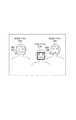
図4に、このときのディスプレイ108に表示される画像の例を示す。検出された顔を覆う矩形の顔検出枠が表示され、その近傍には撮影回数が表示されている。この顔検出枠の形は矩形に限定されるものではなく、楕円形や、検出された顔の輪郭に沿う形であっても構わない。本実施形態では、未撮影の人物と判定された顔には顔検出枠の表示のみを行い、撮影回数の表示は行わない。また、未撮影の顔を囲う顔検出枠と、撮影済みの顔を囲う顔検出枠の色を異ならしめることにより、ユーザーが容易に撮影済みか否かを判定することができる。本実施形態では未撮影の顔を囲う顔検出枠を黄色で表示し、撮影済みの顔を囲う顔検出枠を橙色で表示している。なお、未撮影の顔が検出された場合、その旨を音声で示す構成としても良い。 FIG. 4 shows an example of an image displayed on the
ステップS115にて、CPU114は、ステップS104にて顔検出処理が成功していれば、検出された顔の位置を基準として、焦点調節回路126と露出量調節回路127を制御し、焦点調節処理および露出量調節処理を行う。この焦点調節処理および露出量調節処理は、図ではAF、AEと記してある。ステップS104で顔検出処理に失敗していれば、公知の手法、例えば中央エリアの重み付けを周囲のエリアよりも大きくした中央重点法を用いた焦点調節処理、露出量調節処理を行う。 In step S115, if the face detection process is successful in step S104, the CPU 114 controls the focus adjustment circuit 126 and the
ステップS116にて、CPU114はシャッターボタン118が半押しされてスイッチSW1がオンされたかを判定する。スイッチSW1がオンされていればステップS117に進み、オンされていなければステップS103に戻る。 In step S116, CPU 114 determines whether
スイッチSW1がオンされれば、焦点状態および露出量を固定し、シャッターボタン118が全押しされてスイッチSW2がオンされるまで待機する。
ステップS117にて、撮像素子102の出力を用いて表示用画像データを更新し、ディスプレイ108に表示する被写体像を更新する。If the switch SW1 is turned on, the focus state and the exposure amount are fixed, and the process waits until the
In step S117, the display image data is updated using the output of the
ステップS118にて、CPU114はシャッターボタン118が全押しされてスイッチSW2がオンされたかを判定する。スイッチSW2がオンされれば図3のステップS121に進み、オンされていなければステップS116に戻る。スイッチSW2がオンされることなく、スイッチSW1がオンされた状態が保持されると、ステップS116、S117を繰り返し、顔検出や焦点調節が行われることなく、ディスプレイ108に表示される画像の更新のみが継続される。 In step S118, CPU 114 determines whether
このように本実施形態では、被写体の様子を観察するモニター処理において、ディスプレイ108に表示されている被写体が撮影済みであるか、および、何回撮影されたかを一目で把握することができる。したがって、カメラマンとしてパーティーや遠足といった行事に参加した場合、これらの団体のメンバーを把握していなくとも、この団体に撮像装置100を向けるだけで、誰が撮影済みでないのかを容易に把握することができる。 As described above, in the present embodiment, in the monitor process for observing the state of the subject, it is possible to grasp at a glance how many times the subject displayed on the
フローチャートに戻り、ステップS118でスイッチSW2がオンされると、図3のステップS121に進み、CPU114は撮影処理を行う。撮像素子102から出力されたアナログの画像データをA/Dコンバータ103にてデジタルの画像データに変換し、画像処理回路104にて輝度値の修正およびホワイトバランス調節が施され、メモリ上に画像データとして記録される。さらにこの画像データを圧縮した表示用画像データをDRAM119異なる領域に生成する。画像処理回路104は画像データを圧縮して記録用画像データを生成する。 Returning to the flowchart, when the switch SW2 is turned on in step S118, the process proceeds to step S121 in FIG. 3, and the CPU 114 performs a photographing process. The analog image data output from the
ステップS122にて、CPU114はメモリカードコントローラ113を用いて記録用画像データをメモリカード111に転送する。
ステップS123にて、特徴検出回路121がDRAM119に記憶された表示用画像データを読出し、パラメータ保持回路124から読み出したパラメータを用いて、画像データから顔の検出処理を行い、特徴値を算出する。In
In step S123, the feature detection circuit 121 reads display image data stored in the DRAM 119, performs face detection processing from the image data using the parameters read from the parameter holding circuit 124, and calculates feature values.
ステップS124にて、CPU114はステップS123での顔検出処理が成功したかを判定し、成功していればステップS125に進み、失敗していればステップS137に進む。ステップS137ではDRAM119に記憶された表示用画像データを用いてディスプレイに画像を表示し、図2のステップS103に戻る。 In step S124, the CPU 114 determines whether the face detection process in step S123 has succeeded. If successful, the process proceeds to step S125, and if unsuccessful, the process proceeds to step S137. In step S137, an image is displayed on the display using the display image data stored in the DRAM 119, and the process returns to step S103 in FIG.
ステップS125にて、CPU114は撮影履歴スイッチ125がオンされているかを判定する。撮影履歴スイッチ125がオンされていればステップS126に進み、特徴値記憶回路122から履歴期間に記憶された特徴値、後述する履歴フラグが設定された特徴値を読み出す。 In step S125, CPU 114 determines whether shooting history switch 125 is turned on. If the photographing history switch 125 is turned on, the process proceeds to step S126, and the feature value stored in the history period and the feature value in which a history flag described later is set are read from the feature
ステップS127にて、履歴フラグが設定されている特徴値と、ステップS124にて得られた特徴値を比較する。そして比較した結果、これらの特徴値の類似度が基準となるレベルを満たしており、これらの特徴値が同一の被写体に対するものであると判定された場合はステップS128に進み、そうでなければステップS129に進む。 In step S127, the feature value for which the history flag is set is compared with the feature value obtained in step S124. As a result of the comparison, if it is determined that the similarity between these feature values satisfies a reference level and these feature values are for the same subject, the process proceeds to step S128; The process proceeds to S129.
ステップS128にて、特徴値に付随して記憶された撮影回数に1を加え、ステップS131に進む。この撮影回数は初期値として0が設定されており、このステップS128を通るたびに1ずつ増加する。 In step S128, 1 is added to the number of times of photographing stored along with the feature value, and the process proceeds to step S131. The number of times of photographing is set to 0 as an initial value, and increases by 1 every time this step S128 is passed.
ステップS129にて、特徴値記憶回路122はステップS124にて算出された特徴値を、新たに検出された被写体の特徴値として記憶する。つまり、このステップS129を通る度に、特徴値記憶回路122に特徴値が記憶された被写体の数が増加する。 In step S129, the feature
そしてステップS130にて、ステップS129にて記憶された特徴値に対して履歴フラグを立て、ステップS131に進む。 In step S130, a history flag is set for the feature value stored in step S129, and the process proceeds to step S131.
ステップS131にて、特徴値比較回路123がステップS124にて検出された全ての顔に対しての特徴値の比較が済んでいればステップS136に進む。済んでいなければステップS125に戻り、残りの顔に対しても特徴値の比較を行う。 In step S131, if the feature
ステップS136にて、CPU114は検出したそれぞれの顔に対してシステム記憶部109に記憶した座標データを参照し、ディスプレイ108に、顔の大きさに沿わせた顔検出枠を被写体像に重畳させた画像を表示させ、図2のステップS103に戻る。 In step S136, the CPU 114 refers to the coordinate data stored in the
このように、撮影履歴スイッチがオンされていると、撮影された画像データから検出された顔の特徴値が、特徴値記憶回路122に記憶された特徴値と類似すれば、ステップS128にてその被写体の撮影回数をインクリメントする。モニター処理時には、CPU114がステップS114にてこの撮影回数を被写体像の近傍に表示するため、ユーザーがその被写体の撮影回数を容易に把握することができる。また、特徴値記憶回路122は撮影回数をインクリメントするだけでなく、このとき得られた特徴値を追加記憶する。同一の被写体に対する特徴値の情報は、その数が多いほど一致の判定における精度が高くなるためである。 As described above, when the photographing history switch is turned on, if the facial feature value detected from the photographed image data is similar to the feature value stored in the feature
また、撮影された画像データから検出された顔の特徴値が、特徴値記憶回路122に記憶された特徴値と類似しないのであれば、ステップS129にて新たな被写体の特徴値として、その値を特徴値記憶回路122に記憶する。ステップS130にてこの特徴値に履歴フラグを設定することで、この特徴値が、履歴期間に新たに検出された被写体の特徴値であることを識別できるようにしている。 If the feature value of the face detected from the captured image data is not similar to the feature value stored in the feature
フローチャートのステップS125に戻り、撮影履歴スイッチ125がオンされていなければステップS132に進む。 Returning to step S125 of the flowchart, if the photographing history switch 125 is not turned on, the process proceeds to step S132.
ステップS132では、特徴値比較回路123は特徴値記憶回路122から全ての特徴値を読み出す。この特徴値にはメモリカード111またはシステム記憶部109から読み出した特徴値も含まれる。 In step S <b> 132, the feature
ステップS133にて、特徴値記憶回路122から読み出した全ての特徴値と、ステップS124にて得られた特徴値を比較する。そして比較した結果、これらの特徴値の類似度が基準となるレベルを満たしており、これらの特徴値が同一の被写体に対するものであると判定された場合はステップS134に進み、そうでなければステップS135に進む。In step S1 33, compared with all the feature values read from the feature
ステップS134にて、特徴値に付随して記憶された撮影回数に1を加え、ステップS131に進む。この撮影回数は初期値として0が設定されており、このステップS134を通るたびに1ずつ増加する。 In step S134, 1 is added to the number of times of photographing stored along with the feature value, and the process proceeds to step S131. The number of times of photographing is set to 0 as an initial value, and increases by 1 every time this step S134 is passed.
ステップS135にて、特徴値記憶回路122はステップS124にて算出された特徴値を、新たに検出された被写体の特徴値として記憶し、ステップS131に進む。つまり、このステップS135を通る度に、特徴値記憶回路122に特徴値が記憶された被写体の数が増加する。撮影履歴スイッチがオンされていない場合は、新たな被写体の特徴値が得られた場合であっても履歴フラグは設定されない。このように、撮影履歴スイッチがオンされていない場合は、オンされている場合と比較して、新たな被写体に対する特徴値が検出された場合に、この特徴値に履歴フラグを設定しない点で異なっている。 In step S135, the feature
ここで、撮像装置100に撮影履歴スイッチを備え、履歴期間を設けたことの効果について説明する。
例えばユーザーがプロのカメラマンであり、撮影の対象となる被写体が毎回異なるのであれば、この履歴期間を設ける必要はない。撮影の対象となる被写体が毎回異なるのであれば、今までにその被写体を撮影したことがあるか否かだけを把握できれば良いからである。Here, an effect obtained by providing the imaging history switch in the
For example, if the user is a professional photographer and the subject to be photographed is different every time, there is no need to provide this history period. This is because if the subject to be photographed is different every time, it is only necessary to know whether or not the subject has been photographed so far.
しかしながら撮影の対象となる被写体が、それよりも前の別の撮影での被写体と同一である場合には不都合が生じることがある。例えば、あるパーティーの被写体にA氏が含まれていたとする。このA氏は、それよりも前に行われた別の行事にも参加しており、この行事で既に撮影されているため、特徴値記憶回路122にA氏に対する特徴値が記憶されているものとする。すると、A氏はこのとき行われているパーティーでは1枚も撮影されていないにも関わらず、モニター処理時にディスプレイに写ったA氏の横には、既に撮影が済んでいることを表す撮影回数が表示されてしまうことになる。ディスプレイを見たカメラマンは、A氏はこのパーティーでの撮影が済んでいる人だと勘違いしてしまい、このパーティーにおけるA氏の画像データを得ることなく撮影を終えてしまう可能性がある。 However, there may be a problem when the subject to be photographed is the same as the subject in another previous photographing. For example, assume that Mr. A is included in the subject of a party. Since Mr. A participated in another event held before that, and has already been photographed at this event, the feature value for Mr. A is stored in the feature
そこで、本実施形態では、撮影履歴スイッチ125がオンされて履歴期間が設定された場合は、履歴期間の間でのみ撮影された人を撮影済みとしてカウントするようにしている。履歴期間の間に新たに検出された顔についてのみ、特徴値に履歴フラグを設定することで、この識別を行えるようにしている。 Therefore, in this embodiment, when the shooting history switch 125 is turned on and a history period is set, a person who has been shot only during the history period is counted as having been shot. Only the face newly detected during the history period can be identified by setting a history flag in the feature value.
撮影履歴スイッチ125をオフして履歴期間を解除すると、この特徴値に設定された履歴フラグの設定を解除するように構成されている。先程のA氏の事例に適用すると、先の行事が行われている間だけ撮影履歴スイッチ125をオンしておけば、モニター処理時には、A氏の近傍にはこの行事の間にA氏が撮影された撮影回数のみが表示されることになる。行事が終了後に撮影履歴スイッチ125を解除すれば、特徴値に設定された履歴フラグは全て解除される。そして、パーティーの開始時に再び撮影履歴スイッチ125をオンすると、モニター処理時には、A氏の近傍にはこのパーティーの間にA氏が撮影された撮影回数のみが表示されることになる。 When the shooting history switch 125 is turned off to cancel the history period, the history flag set in the feature value is canceled. Applying to the case of Mr. A, if the shooting history switch 125 is turned on only while the previous event is being performed, Mr. A will be shooting in the vicinity of Mr. A during this event during the monitoring process. Only the number of shots taken is displayed. If the shooting history switch 125 is released after the event ends, all the history flags set in the feature values are released. Then, when the shooting history switch 125 is turned on again at the start of the party, only the number of shootings in which Mr. A was shot during this party is displayed near Mr. A during the monitor process.
このように、本実施形態によれば、事前に被写体の画像データを集めずとも、ユーザーの意図する期間内の間に、撮影済みであるか、あるいは、何枚撮影されたかについて容易に把握することができる。 As described above, according to the present embodiment, it is possible to easily grasp the number of shots or the number of shots that have been taken within the period intended by the user without collecting image data of the subject in advance. be able to.
なお、本実施形態では履歴期間の設定方法として、撮影履歴スイッチ125のオン/オフの切り換えを例にあげたが、これに限定されるものではない。履歴期間の設定方法としては、他にも様々な方法が考えられる。例えば、開始時と終了時の日時をユーザーに指定させる方法、日時に応じて撮像装置が自動的に設定する方法、あるいは、全自動やポートレートモードのように撮影モードの変化に応じて自動的に設定する方法などが考えられる。 In the present embodiment, as an example of setting the history period, the shooting history switch 125 is switched on / off. However, the present invention is not limited to this. There are various other methods for setting the history period. For example, a method that allows the user to specify the start and end date and time, a method that the imaging device automatically sets according to the date and time, or automatically according to changes in the shooting mode such as fully automatic or portrait mode The method of setting to can be considered.
また、被写体の特徴値の記憶方法として、撮像装置100内のシステム記憶部109に記憶させる方法と、メモリカード111に記憶させる方法とが考えられる。いずれの場合も必要に応じて、記憶された特徴値を特徴記憶回路122に転送することで用いる。検出の対象となる被写体に応じて特徴値を記憶先を変更すれば、より多くの特徴値を記憶させることが可能となる。また、撮影中にメモリカード111の容量が不足し、メモリカード111を交換する必要に迫られた場合は、メモリカード111に記憶された特徴値をシステム記憶部109に転送すればよい。また、撮影して得られた画像データと特徴値を関連付け、ある被写体の画像データを全て消去した場合に、これに対応する特徴値を自動的に消去する構成とすると使い勝手が向上する。 Further, as a method for storing the feature value of the subject, a method of storing in the
(第2の実施形態)
次に図5に示すフローチャートを用いて撮像装置100の別の撮影処理を説明する。図5に示すフローチャートは、モニター処理時に常に顔検出を行うのではなく、被写体の様子に変化が生じたと判定された場合のみ顔検出を行う点が、図3に示すフローチャートと異なる。(Second Embodiment)
Next, another imaging process of the
図5のステップのうち、図2に示すフローチャートと同じ処理を行うステップには、図2と同じ番号が付されている。 Of the steps in FIG. 5, steps that perform the same processing as in the flowchart shown in FIG. 2 are assigned the same numbers as in FIG.
撮影モードが設定されると、ステップS101にて、CPU114は撮影履歴スイッチ125の状態の確認を行う。 When the shooting mode is set, the CPU 114 checks the state of the shooting history switch 125 in step S101.
ステップS102にて、CPU114は撮像素子102の出力を用いて表示用画像データを生成し、ディスプレイ108に被写体の画像を表示するモニター処理を開始させる。 In step S <b> 102, the CPU 114 generates display image data using the output of the
ステップS103にて、撮像素子102が光電変換を行ってアナログの画像データを出力し、画像処理回路104がこのアナログの画像データから得られたデジタルの画像データを基に表示用画像データを生成し、DRAM119に記憶する。そしてディスプレイ108がこの表示用画像データを用いて被写体像を表示する。 In step S103, the
次にステップS201にて、ディスプレイ108に顔検出枠が表示されているかを判定し、表示されていなければ顔検出処理を行う必要があるため、ステップS104に進む。ディスプレイ108に顔検出枠が表示されていれば、顔検出処理を行う必要性を判定するためにステップS202に進む。 Next, in step S201, it is determined whether or not a face detection frame is displayed on the
ステップS202では、ステップS103で得られた画像データと、直前の顔検出処理が行われた画像データの輝度値を比較し、その差が基準レベルを超えていれば被写体に変化が生じたとしてステップS104に進む。被写体に変化が生じていないと判定した場合は、被写体に変化がないと推定し、新たな顔検出処理は不要であると判断する。そして顔検出処理を行うことなくステップS115に進む。なお、このステップS202における被写体の変化の有無の判定は、他の方法であっても構わない。例えば、対物レンズ群101内のズームレンズの駆動の有無や、撮像装置100の姿勢情報、あるいは、撮像装置100に搭載された不図示の角速度センサの出力結果を用いてもよい。 In step S202, the luminance values of the image data obtained in step S103 and the image data subjected to the previous face detection process are compared. If the difference exceeds the reference level, the subject is assumed to have changed. The process proceeds to S104. If it is determined that there is no change in the subject, it is estimated that there is no change in the subject, and it is determined that a new face detection process is unnecessary. Then, the process proceeds to step S115 without performing face detection processing. The determination of whether or not the subject has changed in step S202 may be another method. For example, the presence / absence of driving of the zoom lens in the objective lens group 101, the attitude information of the
ステップS104以降の処理については、図3に示すフローチャートと同じである。 The processing after step S104 is the same as the flowchart shown in FIG.
以上のように、本実施形態によれば、ディスプレイ108に顔検出枠が表示されている場合は、被写体に変化が生じたと推定された場合のみ、新たな顔検出処理を行う。このため、特徴検出回路121や特徴値比較回路123にかかる負荷を低減させることができ、撮像装置100の消費エネルギーを低減させることができる。 As described above, according to the present embodiment, when a face detection frame is displayed on the
(第3の実施形態)
次に図6に示すフローチャートを用いて撮像装置100の更に別の撮影処理を説明する。図6に示すフローチャートは、焦点調節処理および露出量調節処理に、顔検出結果を反映させていない点で上記の実施形態とは異なる。(Third embodiment)
Next, still another shooting process of the
モードスイッチ116によって撮影モードが設定されると、図6に示すフローチャートが開始される。
ステップS101にて、CPU114は撮影履歴スイッチ125の状態の確認を行う。撮影履歴スイッチ125がオンされていれば履歴期間が設定されていると判定する。When the shooting mode is set by the
In step S <b> 101, the CPU 114 confirms the state of the shooting history switch 125. If the photographing history switch 125 is turned on, it is determined that the history period is set.
ステップS102にて、CPU114は撮像素子102の出力を用いて表示用画像データを生成し、ディスプレイ108に被写体の画像を表示するモニター処理を開始させる。 In step S <b> 102, the CPU 114 generates display image data using the output of the
ステップS103にて、撮像素子102が光電変換を行ってアナログの画像データを出力し、画像処理回路104がこのアナログの画像データから得られたデジタルの画像データを基に表示用画像データを生成し、DRAM119に記憶する。そしてディスプレイ108がこの表示用画像データを用いて被写体像を表示し、ステップS301に進む。 In step S103, the
ステップS301にて、CPU114はシャッターボタンが半押しされてスイッチSW1がオンしたかを判定する。スイッチSW1がオンされていればステップS302に進み、オンされていなければステップS103に戻る。 In step S301, the CPU 114 determines whether the switch SW1 is turned on by pressing the shutter button halfway. If the switch SW1 is turned on, the process proceeds to step S302, and if not, the process returns to step S103.
ステップS302にて、CPU114は焦点調節回路126と露出量調節回路127を制御し、表示用画像データを用いて焦点調節処理および露出量調節処理を行わせる。 In step S302, the CPU 114 controls the focus adjustment circuit 126 and the exposure
ステップS303にて、CPU114はディスプレイ108に、焦点調節の対象となったエリアを示す枠を被写体像に重畳させた画像を表示させる。この枠を、以下AF枠という。 In step S <b> 303, the CPU 114 causes the
ステップS104にて、特徴検出回路121がDRAM119に記憶された表示用画像データを読出し、パラメータ保持回路124から読み出したパラメータを用いて、画像データから顔の検出処理を行い、特徴値を算出する。複数の顔が検出された場合には、それぞれの顔に対して特徴値を算出する。 In step S104, the feature detection circuit 121 reads the display image data stored in the DRAM 119, performs face detection processing from the image data using the parameters read from the parameter holding circuit 124, and calculates a feature value. When a plurality of faces are detected, a feature value is calculated for each face.
ステップS105にて、CPU114はステップS104での顔の検出処理が成功したかを判定し、成功していればステップS106に進み、失敗していればステップS106からステップS114をとばしてステップS118に進む。 In step S105, the CPU 114 determines whether the face detection process in step S104 has succeeded. If it has succeeded, the process proceeds to step S106, and if it has failed, the process proceeds from step S106 to step S114 and proceeds to step S118. .
顔の検出処理が成功してステップS106に進んだのであれば、CPU114は撮影履歴スイッチ125がオンされているかを判定する。撮影履歴スイッチ125がオンされていればステップS107に進み、特徴値記憶回路122から履歴期間に記憶された特徴値、つまり、履歴フラグが設定された特徴値を読み出す。履歴期間に記憶された特徴値については後ほど説明を行う。 If the face detection process is successful and the process proceeds to step S106, the CPU 114 determines whether the shooting history switch 125 is turned on. If the photographing history switch 125 is turned on, the process proceeds to step S107, and the feature value stored in the history period, that is, the feature value for which the history flag is set is read from the feature
撮影履歴スイッチ125がオンされていなければステップS108に進み、特徴値記録回路122から全ての特徴値を読み出す。この特徴値にはメモリカード111またはシステム記憶部109から読み出した特徴値も含まれる。 If the photographing history switch 125 is not turned on, the process proceeds to step S108, and all feature values are read from the feature
ステップS109にて、特徴値比較回路123はステップS107あるいはステップS108で読み出した特徴値と、ステップS104にて得られた特徴値を比較する。そして比較した結果、これらの特徴値の類似度が基準となるレベルを満たしており、これらの特徴値が同一の被写体に対するものであると判定された場合はステップS110に進み、そうでなければステップS111に進む。 In step S109, the feature
ステップS110にて、CPU114は特徴値記憶回路122から、同一の被写体と判定された特徴値に付随して記憶された撮影回数を読み出し、システム記憶部109に撮影回数を記憶させる。この撮影回数は、付随する特徴値を有する被写体が何回撮影されたかを示すものである。特徴値記憶回路122には、履歴期間が設定されている間に撮影された回数と、履歴期間に関係なく今までに撮影された全ての回数とが別々に記憶されている。 In step S <b> 110, the CPU 114 reads out the number of times of photographing stored along with the feature value determined to be the same subject from the feature
ステップS111にて、CPU114はシステム記憶部109に、ステップS104にて検出された顔の座標データを記憶させる。 In step S111, the CPU 114 causes the
ステップS112にて、特徴値比較回路123がステップS104にて検出された全ての顔に対しての特徴値の比較が済んでいればステップS113に進む。済んでいなければステップS106に戻り、残りの顔に対しても特徴値の比較を行う。 In step S112, if the feature
ステップS113にて、CPU114は検出したそれぞれの顔に対してシステム記憶部109に記憶した座標データを参照し、ディスプレイ108に、顔の大きさに沿わせた顔検出枠を被写体像に重畳させた画像を表示させる。 In step S113, the CPU 114 refers to the coordinate data stored in the
ステップS114にて、CPU114はさらにディスプレイ108に、検出したそれぞれの顔に対して、顔検出枠の近傍にシステム記憶部109に記憶させた撮影回数を被写体像に重畳させた画像を表示させる。 In step S114, the CPU 114 further causes the
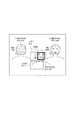
図7に、このときのディスプレイ108に表示される画像の例を示す。検出された顔を覆う矩形の顔検出枠が表示され、その近傍には撮影回数が表示されている。AF枠と顔検出枠を同時に表示すると、具合によっては、どの枠が何を示すのかがユーザーにとってわかり難いものになってしまうおそれがある。そこで本実施形態では、顔検出枠のみを例えば0.5秒周期で点滅させるものとする。 FIG. 7 shows an example of an image displayed on the
さらに、AF枠、未撮影の顔を囲う顔検出枠、および、撮影済みの顔を囲う顔検出枠の色を互いに異ならしめることにより、ユーザーが容易に撮影済みか否かを判定することができる。本実施形態ではAF枠を緑色で、未撮影の顔を囲う顔検出枠を黄色で表示し、撮影済みの顔を囲う顔検出枠を橙色で表示している。また、図7では未撮影の顔を囲う顔検出枠の近傍に未撮影であることを示す星印を表示することで、ユーザーが未撮影の顔をより発見しやすいようにしている。 Furthermore, by making the AF frame, the face detection frame surrounding the unphotographed face, and the face detection frame surrounding the photographed face different from each other, it is possible to determine whether or not the user has already photographed. . In this embodiment, the AF frame is displayed in green, the face detection frame surrounding an unphotographed face is displayed in yellow, and the face detection frame surrounding a captured face is displayed in orange. In FIG. 7, an asterisk indicating that an image has not been taken is displayed in the vicinity of the face detection frame surrounding the unphotographed face, so that the user can more easily find an unphotographed face.
ステップS114にてディスプレイ108に表示を行わせると、ステップS118にて、CPU114はスイッチSW2がオンされたかを判定する。以降の処理は第1の実施形態と同じである。 When display is performed on the
本実施形態ではAF枠と顔検出枠を別々に表示することにより、どの顔に焦点があっているのかを明確に把握することができる。 In the present embodiment, by displaying the AF frame and the face detection frame separately, it is possible to clearly grasp which face is in focus.
このように、上述した実施形態では、被写体の特徴値を撮影中に特徴値記憶回路122に記憶する処理ついて説明を行ったが、特徴値を別の方法で特徴値記録回路122に記憶する処理についても触れておく。 As described above, in the above-described embodiment, the process of storing the feature value of the subject in the feature
図8を用いて特徴値を特徴値記憶回路122に記憶させる処理を説明する。
図8に示すフローチャートは、モードスイッチ116によって登録モードが選択されることで登録処理を開始する。A process of storing the feature value in the feature
The flowchart shown in FIG. 8 starts the registration process when the registration mode is selected by the
ステップS401にて、CPU114は撮像素子102の出力を用いて表示用画像データを生成し、ディスプレイ108に被写体の画像を表示するモニター処理を開始させる。 In step S <b> 401, the CPU 114 generates display image data using the output of the
ステップS402にて、CPU114はシャッターボタン118が半押しされてスイッチSW1がオンされたかを判定する。スイッチSW1がオンされていればステップS403に進み、オンされていなければ待機する。 In step S402, the CPU 114 determines whether the
ステップS403にて、特徴検出回路121がDRAM119に記憶された表示用画像データを読出し、パラメータ保持回路124から読み出したパラメータを用いて、画像データから顔の検出処理を行い、特徴値を算出する。複数の顔が検出された場合には、それぞれの顔に対して特徴値を算出する。 In step S403, the feature detection circuit 121 reads the display image data stored in the DRAM 119, performs face detection processing from the image data using the parameters read from the parameter holding circuit 124, and calculates a feature value. When a plurality of faces are detected, a feature value is calculated for each face.
ステップS404にて、CPU114はステップS403での顔の検出処理が成功したかを判定し、成功していればステップS405に進む。失敗していればステップS402に戻って新たに画像を読み込み、再びスイッチSW1がオンされるまで待機する。 In step S404, the CPU 114 determines whether the face detection process in step S403 is successful. If successful, the process proceeds to step S405. If unsuccessful, the process returns to step S402 to newly read an image, and waits until the switch SW1 is turned on again.
ステップS405にて、CPU114は検出したそれぞれの顔の座標データを参照し、ディスプレイ108に、顔の大きさに沿わせた顔検出枠を被写体像に重畳させた画像を表示させる。ここで顔が複数検出された場合は、最も面積の大きな顔と、その他の顔とで顔検出枠の色を異ならしめる。例えば最も面積の大きな顔にかかる顔検出枠を黄色とし、他の顔にかかる顔検出枠を橙色とする。 In step S405, the CPU 114 refers to the detected coordinate data of each face, and causes the
ステップS406にて、送りボタン117が操作されたかを判定する。送りボタン117が操作されることを検知すると、ステップS407において、その操作に応じて、顔検出枠を黄色にて表示すべき顔を変更する。 In step S406, it is determined whether or not the feed button 117 has been operated. When it is detected that the feed button 117 is operated, in step S407, the face whose face detection frame should be displayed in yellow is changed according to the operation.
ステップS408にて、シャッターボタン118が全押しされてスイッチSW2がオンされたかを判定する。スイッチSW2がオンされない場合はステップS406に戻る。スイッチSW2がオンされると、ステップS409にて、その時点で黄色で顔検出枠が表示されていた顔の特徴値をシステム記憶部109あるいはメモリカード111に記憶し、ステップS402に戻る。ここで特徴値を記憶させようとした被写体の別の特徴値が既にメモリカード111に記憶されている場合には、特徴値を追加するか、あるいは上書きする。登録モードにて検出された特徴値は、撮影中に検出された特徴値よりも、正確な情報であると推定されるためである。
上記の処理をモードスイッチ116によって登録モードが解除されるまで行う。In step S408, it is determined whether the
The above processing is performed until the registration mode is canceled by the
次に、図9を用いて特徴値を特徴値記憶回路122に記憶させる別の処理を説明する。 Next, another process for storing the feature value in the feature
図9に示すフローチャートは、モードスイッチ116によって再生モードが選択され、かつ、メニュー画面から特徴値の登録に関するコマンドを選択することで登録処理を開始する。 In the flowchart shown in FIG. 9, the registration process is started by selecting a reproduction mode by the
ステップS501にて、CPU114は既に撮影された画像データをメモリカード111から読み出す。 In step S <b> 501, the CPU 114 reads out already captured image data from the memory card 111.
ステップS502にて、読み出した画像データをDRAM119に展開し、表示回路106を用いてディスプレイ108に展開された画像データのいずれかを表示する。 In step S502, the read image data is developed in the DRAM 119, and any of the developed image data is displayed on the
ステップS503にて、CPU114は送りボタン117が操作されたかを判定する。送りボタン117が操作されていれば、ステップS504にて、その操作に応じて、ディスプレイ108に表示する画像を切り換える。 In step S503, the CPU 114 determines whether the feed button 117 has been operated. If the feed button 117 has been operated, the image displayed on the
そしてステップS402にて、CPU114はシャッターボタン118が半押しされてスイッチSW1がオンされたかを判定する。スイッチSW1がオンされていればステップS403に進み、オンされていなければステップS503に戻る。 In step S402, the CPU 114 determines whether the
ステップS403にて、特徴検出回路121が、パラメータ保持回路124から読み出したパラメータを用いて、ディスプレイ108に表示されている表示用画像データから顔の検出処理を行い、特徴値を算出する。複数の顔が検出された場合には、それぞれの顔に対して特徴値を算出する。 In step S403, the feature detection circuit 121 uses the parameters read from the parameter holding circuit 124 to perform face detection processing from the display image data displayed on the
ステップS404にて、CPU114はステップS403での顔の検出処理が成功したかを判定し、成功していればステップS405に進む。失敗していればステップS503に戻って新たに画像を読み込み、再びスイッチSW1がオンされるまで待機する。 In step S404, the CPU 114 determines whether the face detection process in step S403 is successful. If successful, the process proceeds to step S405. If unsuccessful, the process returns to step S503 to newly read an image, and waits until the switch SW1 is turned on again.
ステップS405にて、CPU114は検出したそれぞれの顔の座標データを参照し、ディスプレイ108に、顔の大きさに沿わせた顔検出枠を被写体像に重畳させた画像を表示させる。ここで顔が複数検出された場合は、最も面積の大きな顔と、その他の顔とで顔検出枠の色を異ならしめる。例えば最も面積の大きな顔にかかる顔検出枠を黄色とし、他の顔にかかる顔検出枠を橙色とする。 In step S405, the CPU 114 refers to the detected coordinate data of each face, and causes the
ステップS406にて、送りボタン117が操作されたかを判定する。送りボタン117が操作されていれば、ステップS407にて、その操作に応じて、顔検出枠を黄色にて表示すべき顔を変更する。 In step S406, it is determined whether or not the feed button 117 has been operated. If the feed button 117 has been operated, in step S407, the face whose face detection frame should be displayed in yellow is changed according to the operation.
ステップS408にて、シャッターボタン118が全押しされてスイッチSW2がオンされたかを判定する。スイッチSW2がオンされない場合はステップS503に戻る。スイッチSW2がオンされると、ステップS409にて、その時点で黄色にて顔検出枠が表示されていた顔の特徴値をシステム記憶部109あるいはメモリカード111に記憶し、ステップS402に戻る。ここで特徴値を記憶させようとした被写体の別の特徴値が既にメモリカード111に記憶されている場合には、特徴値を追加するか、あるいは上書きする。登録モードにて検出された特徴値は、撮影中に検出された特徴値よりも、正確な情報であると推定されるためである。 In step S408, it is determined whether the
上記の処理をメニュー画面から特徴値の登録に関する処理を解除するコマンドが選択されるまで行う。 The above processing is performed until a command for canceling processing related to feature value registration is selected from the menu screen.
上述の図8、9に示すように、わざわざ撮影時以外の状況を用いて被写体の特徴値を記憶させる場合は、その被写体が検出されたことを、他の被写体が検出されたことよりも明確にしらしめる必要があると予想される。 As shown in FIGS. 8 and 9 above, when the feature value of a subject is purposely stored using a situation other than shooting, it is clearer that the subject is detected than when another subject is detected. It is expected that it will need to be squeezed.
そこで、図8、9に示すフローチャートのように、撮影中以外に特徴値を記憶する場合には、その旨を示す優先フラグを特徴値とあわせて記憶する。そして、撮影中にこの優先フラグを備えた特徴値に類似する被写体を検出した場合には、図10に示すように、その被写体が目立つよう他の被写体とは異なる形態の表示を行う。 Therefore, as shown in the flowcharts of FIGS. 8 and 9, when a feature value is stored other than during shooting, a priority flag indicating that is stored together with the feature value. Then, when a subject similar to the feature value having this priority flag is detected during shooting, as shown in FIG. 10, a display different from other subjects is displayed so that the subject is conspicuous.
この表示を行うことで、ユーザーはディスプレイ108に写った被写体を見逃すことなく撮影することが可能となる。 By performing this display, the user can take a picture without missing the subject on the
なお、上記の実施形態では、ディスプレイ108は検出された被写体の静止画の撮影回数を表示したが、これに限られるものではない。動画を撮影するビデオカメラにおいて、検出された被写体の動画における撮影時間を表示したり、動画における登場回数を表示したりする構成であっても構わない。 In the above-described embodiment, the
100 撮像装置
101 対物レンズ群
102 撮像素子
103 A/Dコンバータ
104 画像処理回路
105 データバス
106 表示回路
107 D/Aコンバータ
108 ディスプレイ
109 システム記憶部
110 システム記憶部コントローラ
111 メモリカード
112 メモリソケット
113 メモリカードコントローラ
114 CPU
115 I/Oインターフェース部
116 モードスイッチ
117 送りボタン
118 シャッターボタン
119 DRAM
120 メモリコントローラ
121 特徴検出回路
122 特徴値記憶回路
123 特徴値比較回路
124 パラメータ保持回路
125 撮影履歴スイッチ
126 焦点調節回路
127 露出調節回路
DESCRIPTION OF
115 I /
120 memory controller 121
Claims (4)
Translated fromJapanese前記撮像素子の出力から生成された画像データから、検出対象となる被写体を検出し、検出した被写体の特徴を示す特徴値を演算する検出回路と、
前記検出回路にて演算された特徴値を記憶する記憶回路と、
前記検出回路にて得られた特徴値と、前記記憶回路に記憶されている特徴値を比較し、これらの特徴値が同一の被写体に対する特徴値であるかを判定する比較回路と、
前記撮像素子の出力から生成される画像データを用いて、動画表示を行うディスプレイと、
撮影を指示するための操作部材と、を備え、
前記記憶回路は、前記記憶した特徴値に対応する被写体の静止画の撮影回数、および、動画の撮影時間の少なくとも一方に関する情報を記憶し、
前記記録回路は、前記比較回路によって、前記操作部材が操作されることに応じて得られた画像データから演算した特徴値と前記記憶回路に記憶された特徴値が同一の被写体に対する特徴値でないと判定された場合には、前記操作部材が操作されることに応じて得られた画像データから演算した特徴値を新たな被写体の特徴値として記憶し、同一の被写体に対する特徴値であると判定された場合には、前記同一の被写体と判定された特徴値に対応する被写体の前記静止画の撮影回数、および、動画の撮影時間の少なくとも一方を更新し、
前記ディスプレイは、前記比較回路によって、前記操作部材が操作されることによらずに前記ディスプレイに表示された動画に用いられる画像データから前記検出回路が演算した特徴値と前記記憶回路に記憶された特徴値が同一の被写体に対する特徴値であると判定された場合には、前記同一の被写体と判定された特徴値に対応する被写体の前記静止画の撮影回数、および、動画の撮影時間の少なくとも一方に関する情報を前記動画に表示することを特徴とする撮像装置。An image sensor;
From the image data generated from the output ofthe image sensor, a detection circuit for detecting an object to be detected, and calculates a feature value indicating a feature of a detected object,
A storage circuit for storing feature values calculated by the detection circuit;
A feature value obtained by the detecting circuit, a comparator circuitfor comparing the characteristic value stored in the storagecircuit, these feature values to determine whether a characteristic value for the same object,
A display for displaying a moving image using image data generated from the output of the image sensor;
An operation member for instructing photographing,
The storage circuit stores information relating to at least one of the number of still image shootings of the subject corresponding to the stored feature value and the shooting time of the moving image,
In the recording circuit, the feature value calculated from the image data obtained when the operation member is operated by the comparison circuit and the feature value stored in the storage circuit are not feature values for the same subject. If it is determined, the feature value calculated from the image data obtained in response to the operation of the operation member is stored as the feature value of the new subject, and is determined to be the feature value for the same subject. In the case of updating the at least one of the number of times the still image of the subject corresponding to the characteristic value determined to be the same subject and the shooting time of the video,
The display is stored in the storage circuit with the feature value calculated by the detection circuit from the image data used for the moving image displayed on the display without being operated by the comparison circuit. When it is determined that the feature value is a feature value for the same subject, at least one of the number of times of shooting the still image of the subject corresponding to the feature value determined to be the same subject and the shooting time of the moving image An image pickup apparatus thatdisplays information on the moving image.
前記ディスプレイは、前記設定手段にて前記履歴期間が設定されていると、前記履歴期間が設定されている期間における被写体の前記静止画の撮影回数、および、動画の撮影時間の少なくとも一方に関する情報を表示することを特徴とする請求項1に記載の撮像装置。Having setting means for setting the history period;
When the history period is set by the setting means, the display displays information on at least one of the number of still image shootings of the subject and the video shooting time during the period for which the history period is set. The imaging device according to claim 1, wherein the imaging device isdisplayed .
前記検出工程にて演算された特徴値を記憶手段に記憶する第1の記憶工程と、A first storage step of storing in the storage means the characteristic value calculated in the detection step;
前記検出工程にて得られた特徴値と、前記第1の記憶工程にて記憶した特徴値を比較し、これらの特徴値が同一の被写体に対する特徴値であるかを判定する比較工程と、A comparison step of comparing the feature values obtained in the detection step with the feature values stored in the first storage step and determining whether these feature values are feature values for the same subject;
前記記憶した特徴値に対応する被写体が検出された静止画の撮影回数、および、動画の撮影時間の少なくとも一方に関する情報を前記記憶手段に記憶する第2の記憶工程と、A second storage step of storing, in the storage means, information relating to at least one of the number of still images in which the subject corresponding to the stored feature value is detected and the shooting time of the moving image;
前記撮像素子の出力から生成された画像データを用いて、ディスプレイに動画表示を行う表示工程と、を備え、Using the image data generated from the output of the imaging device, and displaying a moving image on the display,
前記比較工程において、撮影を指示するための操作部材が操作されることに応じて得られた画像データから演算された特徴値と前記記憶回路に記憶された特徴値が同一の被写体に対する特徴値でないと判定した場合には、前記第1の記憶工程において、前記検出回路が演算した特徴値を新たな被写体の特徴値として記憶し、In the comparison step, the feature value calculated from the image data obtained when the operation member for instructing photographing is operated and the feature value stored in the storage circuit are not feature values for the same subject. In the first storage step, the feature value calculated by the detection circuit is stored as a new subject feature value,
前記比較工程において、前記操作部材が操作されることに応じて得られた画像データから演算された特徴値と前記記憶回路に記憶された特徴値が同一の被写体に対する特徴値であると判定した場合には、前記第2の記憶工程において、前記同一の被写体と判定された特徴値に対応する被写体の前記静止画の撮影回数、および、動画の撮影時間の少なくとも一方を更新し、When it is determined in the comparison step that the feature value calculated from the image data obtained by operating the operation member and the feature value stored in the storage circuit are feature values for the same subject In the second storage step, at least one of the number of times the still image of the subject corresponding to the feature value determined to be the same subject and the shooting time of the moving image are updated,
前記比較工程において、前記操作部材が操作されることによらずに前記ディスプレイに表示された動画に用いられる画像データから演算された特徴値と前記記憶回路に記憶された特徴値が同一の被写体に対する特徴値であると判定した場合には、前記表示工程において、前記同一の被写体と判定された特徴値に対応する被写体の前記静止画の撮影回数、および、動画の撮影時間の少なくとも一方に関する情報を前記記憶手段から読み出して前記動画に表示することを特徴とする撮像装置の制御方法。In the comparison step, the feature value calculated from the image data used for the moving image displayed on the display without the operation member being operated is the same as the feature value stored in the storage circuit with respect to the subject. If the characteristic value is determined, the display step includes information on at least one of the number of still image shootings and the video shooting time of the subject corresponding to the feature value determined to be the same subject. A method for controlling an imaging apparatus, comprising: reading from the storage means and displaying the moving image.
Priority Applications (2)
| Application Number | Priority Date | Filing Date | Title |
|---|---|---|---|
| JP2006015096AJP4324170B2 (en) | 2005-03-17 | 2006-01-24 | Imaging apparatus and display control method |
| US11/369,157US7672580B2 (en) | 2005-03-17 | 2006-03-06 | Imaging apparatus and method for controlling display device |
Applications Claiming Priority (2)
| Application Number | Priority Date | Filing Date | Title |
|---|---|---|---|
| JP2005077161 | 2005-03-17 | ||
| JP2006015096AJP4324170B2 (en) | 2005-03-17 | 2006-01-24 | Imaging apparatus and display control method |
Publications (2)
| Publication Number | Publication Date |
|---|---|
| JP2006295888A JP2006295888A (en) | 2006-10-26 |
| JP4324170B2true JP4324170B2 (en) | 2009-09-02 |
Family
ID=37010449
Family Applications (1)
| Application Number | Title | Priority Date | Filing Date |
|---|---|---|---|
| JP2006015096AExpired - Fee RelatedJP4324170B2 (en) | 2005-03-17 | 2006-01-24 | Imaging apparatus and display control method |
Country Status (2)
| Country | Link |
|---|---|
| US (1) | US7672580B2 (en) |
| JP (1) | JP4324170B2 (en) |
Families Citing this family (74)
| Publication number | Priority date | Publication date | Assignee | Title |
|---|---|---|---|---|
| US7565030B2 (en) | 2003-06-26 | 2009-07-21 | Fotonation Vision Limited | Detecting orientation of digital images using face detection information |
| US8948468B2 (en) | 2003-06-26 | 2015-02-03 | Fotonation Limited | Modification of viewing parameters for digital images using face detection information |
| US9129381B2 (en) | 2003-06-26 | 2015-09-08 | Fotonation Limited | Modification of post-viewing parameters for digital images using image region or feature information |
| US7844076B2 (en) | 2003-06-26 | 2010-11-30 | Fotonation Vision Limited | Digital image processing using face detection and skin tone information |
| US9692964B2 (en) | 2003-06-26 | 2017-06-27 | Fotonation Limited | Modification of post-viewing parameters for digital images using image region or feature information |
| US8330831B2 (en) | 2003-08-05 | 2012-12-11 | DigitalOptics Corporation Europe Limited | Method of gathering visual meta data using a reference image |
| US7616233B2 (en) | 2003-06-26 | 2009-11-10 | Fotonation Vision Limited | Perfecting of digital image capture parameters within acquisition devices using face detection |
| US7620218B2 (en) | 2006-08-11 | 2009-11-17 | Fotonation Ireland Limited | Real-time face tracking with reference images |
| US8155397B2 (en) | 2007-09-26 | 2012-04-10 | DigitalOptics Corporation Europe Limited | Face tracking in a camera processor |
| US8896725B2 (en) | 2007-06-21 | 2014-11-25 | Fotonation Limited | Image capture device with contemporaneous reference image capture mechanism |
| US7440593B1 (en) | 2003-06-26 | 2008-10-21 | Fotonation Vision Limited | Method of improving orientation and color balance of digital images using face detection information |
| US7269292B2 (en) | 2003-06-26 | 2007-09-11 | Fotonation Vision Limited | Digital image adjustable compression and resolution using face detection information |
| US7792970B2 (en) | 2005-06-17 | 2010-09-07 | Fotonation Vision Limited | Method for establishing a paired connection between media devices |
| US8989453B2 (en) | 2003-06-26 | 2015-03-24 | Fotonation Limited | Digital image processing using face detection information |
| US7574016B2 (en) | 2003-06-26 | 2009-08-11 | Fotonation Vision Limited | Digital image processing using face detection information |
| US8494286B2 (en) | 2008-02-05 | 2013-07-23 | DigitalOptics Corporation Europe Limited | Face detection in mid-shot digital images |
| US7471846B2 (en) | 2003-06-26 | 2008-12-30 | Fotonation Vision Limited | Perfecting the effect of flash within an image acquisition devices using face detection |
| US8498452B2 (en) | 2003-06-26 | 2013-07-30 | DigitalOptics Corporation Europe Limited | Digital image processing using face detection information |
| US8682097B2 (en) | 2006-02-14 | 2014-03-25 | DigitalOptics Corporation Europe Limited | Digital image enhancement with reference images |
| US8593542B2 (en) | 2005-12-27 | 2013-11-26 | DigitalOptics Corporation Europe Limited | Foreground/background separation using reference images |
| TWI236287B (en)* | 2004-05-19 | 2005-07-11 | Asia Optical Co Inc | Digital camera and manual focus method thereof |
| US8320641B2 (en) | 2004-10-28 | 2012-11-27 | DigitalOptics Corporation Europe Limited | Method and apparatus for red-eye detection using preview or other reference images |
| US7315631B1 (en) | 2006-08-11 | 2008-01-01 | Fotonation Vision Limited | Real-time face tracking in a digital image acquisition device |
| US8503800B2 (en) | 2007-03-05 | 2013-08-06 | DigitalOptics Corporation Europe Limited | Illumination detection using classifier chains |
| JP4507281B2 (en) | 2006-03-30 | 2010-07-21 | 富士フイルム株式会社 | Image display device, imaging device, and image display method |
| JP4823135B2 (en)* | 2006-05-22 | 2011-11-24 | ソニー・エリクソン・モバイルコミュニケーションズ株式会社 | Information processing device, information processing method, information processing program, and portable terminal device |
| EP2033142B1 (en) | 2006-06-12 | 2011-01-26 | Tessera Technologies Ireland Limited | Advances in extending the aam techniques from grayscale to color images |
| JP4338047B2 (en)* | 2006-07-25 | 2009-09-30 | 富士フイルム株式会社 | Imaging device |
| JP4656657B2 (en)* | 2006-07-31 | 2011-03-23 | キヤノン株式会社 | Imaging apparatus and control method thereof |
| US7403643B2 (en) | 2006-08-11 | 2008-07-22 | Fotonation Vision Limited | Real-time face tracking in a digital image acquisition device |
| US7916897B2 (en) | 2006-08-11 | 2011-03-29 | Tessera Technologies Ireland Limited | Face tracking for controlling imaging parameters |
| KR101317016B1 (en) | 2006-10-31 | 2013-10-11 | 캐논 가부시끼가이샤 | Electrophotographic photosensitive body, method for producing electrophotographic photosensitive body, process cartridge, and electrophotographic device |
| US8055067B2 (en) | 2007-01-18 | 2011-11-08 | DigitalOptics Corporation Europe Limited | Color segmentation |
| JP4568918B2 (en)* | 2007-01-30 | 2010-10-27 | 富士フイルム株式会社 | Imaging apparatus and imaging control method |
| JP5049356B2 (en) | 2007-02-28 | 2012-10-17 | デジタルオプティックス・コーポレイション・ヨーロッパ・リミテッド | Separation of directional lighting variability in statistical face modeling based on texture space decomposition |
| JP4970557B2 (en) | 2007-03-05 | 2012-07-11 | デジタルオプティックス・コーポレイション・ヨーロッパ・リミテッド | Face search and detection in digital image capture device |
| JP2008244903A (en)* | 2007-03-28 | 2008-10-09 | Casio Comput Co Ltd | Imaging apparatus, control program, and display control method |
| JP4978271B2 (en)* | 2007-03-28 | 2012-07-18 | カシオ計算機株式会社 | Imaging apparatus, captured image display method and program |
| WO2008133237A1 (en)* | 2007-04-23 | 2008-11-06 | Sharp Kabushiki Kaisha | Image picking-up device, computer readable recording medium including recorded program for control of the device, and control method |
| WO2008131823A1 (en)* | 2007-04-30 | 2008-11-06 | Fotonation Vision Limited | Method and apparatus for automatically controlling the decisive moment for an image acquisition device |
| US7916971B2 (en) | 2007-05-24 | 2011-03-29 | Tessera Technologies Ireland Limited | Image processing method and apparatus |
| US7676145B2 (en)* | 2007-05-30 | 2010-03-09 | Eastman Kodak Company | Camera configurable for autonomous self-learning operation |
| JP2009010777A (en)* | 2007-06-28 | 2009-01-15 | Sony Corp | Imaging device, photography control method, and program |
| JP4961282B2 (en)* | 2007-07-03 | 2012-06-27 | キヤノン株式会社 | Display control apparatus and control method thereof |
| JP2009044463A (en)* | 2007-08-08 | 2009-02-26 | Sanyo Electric Co Ltd | Electronic camera and field image reproduction device |
| JP5046788B2 (en)* | 2007-08-10 | 2012-10-10 | キヤノン株式会社 | Imaging apparatus and control method thereof |
| US8106998B2 (en)* | 2007-08-31 | 2012-01-31 | Fujifilm Corporation | Image pickup apparatus and focusing condition displaying method |
| JP2009118009A (en)* | 2007-11-02 | 2009-05-28 | Sony Corp | Imaging apparatus, method for controlling same, and program |
| JP5040760B2 (en)* | 2008-03-24 | 2012-10-03 | ソニー株式会社 | Image processing apparatus, imaging apparatus, display control method, and program |
| US7855737B2 (en) | 2008-03-26 | 2010-12-21 | Fotonation Ireland Limited | Method of making a digital camera image of a scene including the camera user |
| JP5429445B2 (en)* | 2008-04-08 | 2014-02-26 | 富士フイルム株式会社 | Image processing system, image processing method, and program |
| CN103475837B (en) | 2008-05-19 | 2017-06-23 | 日立麦克赛尔株式会社 | Record reproducing device and method |
| JP5094561B2 (en)* | 2008-05-29 | 2012-12-12 | キヤノン株式会社 | camera |
| JP4582212B2 (en)* | 2008-06-24 | 2010-11-17 | カシオ計算機株式会社 | Imaging apparatus and program |
| JP4640456B2 (en)* | 2008-06-25 | 2011-03-02 | ソニー株式会社 | Image recording apparatus, image recording method, image processing apparatus, image processing method, and program |
| CA2672511A1 (en)* | 2008-07-16 | 2010-01-16 | Verint Systems Inc. | A system and method for capturing, storing, analyzing and displaying data relating to the movements of objects |
| CN102027505A (en) | 2008-07-30 | 2011-04-20 | 泰塞拉技术爱尔兰公司 | Automatic face and skin retouching using face detection |
| JP5029529B2 (en)* | 2008-08-05 | 2012-09-19 | 株式会社Jvcケンウッド | Imaging apparatus, imaging method, image signal reproducing apparatus, and image signal reproducing method |
| JP5147737B2 (en)* | 2009-01-05 | 2013-02-20 | 株式会社日立製作所 | Imaging device |
| JP5388611B2 (en) | 2009-02-03 | 2014-01-15 | キヤノン株式会社 | Imaging apparatus, control method therefor, and program |
| JP2010226558A (en) | 2009-03-25 | 2010-10-07 | Sony Corp | Apparatus, method, and program for processing image |
| JP5366676B2 (en) | 2009-06-22 | 2013-12-11 | キヤノン株式会社 | IMAGING DEVICE, ITS CONTROL METHOD, PROGRAM, AND STORAGE MEDIUM |
| JP5434339B2 (en)* | 2009-07-29 | 2014-03-05 | ソニー株式会社 | Imaging control apparatus, imaging system, imaging method, program |
| US8379917B2 (en) | 2009-10-02 | 2013-02-19 | DigitalOptics Corporation Europe Limited | Face recognition performance using additional image features |
| JP5713821B2 (en)* | 2011-06-30 | 2015-05-07 | キヤノン株式会社 | Image processing apparatus and method, and camera having image processing apparatus |
| EP2549738B1 (en)* | 2011-07-19 | 2013-08-28 | Axis AB | Method and camera for determining an image adjustment parameter |
| JP5375943B2 (en)* | 2011-12-26 | 2013-12-25 | カシオ計算機株式会社 | Imaging apparatus and program thereof |
| JP5246358B2 (en)* | 2012-02-13 | 2013-07-24 | 株式会社Jvcケンウッド | Image signal reproducing apparatus and image signal reproducing method |
| US9049382B2 (en)* | 2012-04-05 | 2015-06-02 | Canon Kabushiki Kaisha | Image processing apparatus and image processing method |
| JP6131948B2 (en)* | 2012-04-09 | 2017-05-24 | ソニー株式会社 | Display control apparatus, display control method, and program |
| US9508119B2 (en)* | 2012-07-13 | 2016-11-29 | Blackberry Limited | Application of filters requiring face detection in picture editor |
| JP5889247B2 (en)* | 2013-07-02 | 2016-03-22 | キヤノン株式会社 | Image processing apparatus, image processing method, image processing program, and imaging apparatus |
| JP2018160799A (en)* | 2017-03-23 | 2018-10-11 | ソニーセミコンダクタソリューションズ株式会社 | Control device, control method, program, and electronic device system |
| WO2019212501A1 (en)* | 2018-04-30 | 2019-11-07 | Hewlett-Packard Development Company, L.P. | Trained recognition models |
Family Cites Families (18)
| Publication number | Priority date | Publication date | Assignee | Title |
|---|---|---|---|---|
| US5031049A (en)* | 1984-05-25 | 1991-07-09 | Canon Kabushiki Kaisha | Automatic object image follow-up device |
| JPH0589244A (en) | 1991-09-27 | 1993-04-09 | Hitachi Ltd | Pattern matching method and device |
| JP3483039B2 (en) | 1993-09-30 | 2004-01-06 | 博文 松尾 | Identification device based on image signals |
| JP3279913B2 (en)* | 1996-03-18 | 2002-04-30 | 株式会社東芝 | Person authentication device, feature point extraction device, and feature point extraction method |
| JPH10162118A (en) | 1996-11-29 | 1998-06-19 | Canon Inc | Image processing apparatus and method |
| JP3469031B2 (en) | 1997-02-18 | 2003-11-25 | 株式会社東芝 | Face image registration apparatus and method |
| JP2000048184A (en) | 1998-05-29 | 2000-02-18 | Canon Inc | Image processing method and face region extraction method and apparatus |
| CN1110767C (en) | 1999-11-12 | 2003-06-04 | 成都银晨网讯科技有限公司 | Face image identification entrance guard and work attendance checking system |
| CN1126066C (en) | 2000-05-31 | 2003-10-29 | 成都银晨网讯科技有限公司 | Face image recognizing IC card and personal authentication system |
| JP2003107335A (en) | 2001-09-28 | 2003-04-09 | Ricoh Co Ltd | Imaging device, automatic focusing method, and program for causing computer to execute the method |
| US7298412B2 (en)* | 2001-09-18 | 2007-11-20 | Ricoh Company, Limited | Image pickup device, automatic focusing method, automatic exposure method, electronic flash control method and computer program |
| JP2004013871A (en) | 2002-06-12 | 2004-01-15 | Creer:Kk | Security system |
| JP4078973B2 (en) | 2002-12-26 | 2008-04-23 | カシオ計算機株式会社 | Image photographing apparatus and program |
| JP2004317699A (en) | 2003-04-15 | 2004-11-11 | Nikon Gijutsu Kobo:Kk | Digital camera |
| JP2004320286A (en) | 2003-04-15 | 2004-11-11 | Nikon Gijutsu Kobo:Kk | Digital camera |
| JP4196714B2 (en) | 2003-04-15 | 2008-12-17 | 株式会社ニコン | Digital camera |
| US20040207743A1 (en)* | 2003-04-15 | 2004-10-21 | Nikon Corporation | Digital camera system |
| JP2004343357A (en) | 2003-05-14 | 2004-12-02 | Konica Minolta Photo Imaging Inc | Recording medium set, image recorder and image recording method |
- 2006
- 2006-01-24JPJP2006015096Apatent/JP4324170B2/ennot_activeExpired - Fee Related
- 2006-03-06USUS11/369,157patent/US7672580B2/ennot_activeExpired - Fee Related
Also Published As
| Publication number | Publication date |
|---|---|
| US20060210264A1 (en) | 2006-09-21 |
| JP2006295888A (en) | 2006-10-26 |
| US7672580B2 (en) | 2010-03-02 |
Similar Documents
| Publication | Publication Date | Title |
|---|---|---|
| JP4324170B2 (en) | Imaging apparatus and display control method | |
| CN106575027B (en) | Camera device and object tracking method thereof | |
| KR100738492B1 (en) | Image capture apparatus and control method therefor | |
| US7817911B2 (en) | Photographic method and apparatus | |
| CN101662587A (en) | Image pick-up apparatus and tracking method therefor | |
| JP2007304280A (en) | IMAGING DEVICE, ITS CONTROL METHOD, PROGRAM, AND STORAGE MEDIUM | |
| JP2009100448A (en) | Imaging apparatus and imaging method | |
| JP2009207119A (en) | Imaging apparatus and program | |
| JP5171468B2 (en) | IMAGING DEVICE AND IMAGING DEVICE CONTROL METHOD | |
| JP2007221312A (en) | Imaging device | |
| JP5180349B2 (en) | Imaging apparatus, method, and program | |
| KR101046041B1 (en) | Imaging device | |
| JP5030022B2 (en) | Imaging apparatus and program thereof | |
| JP2008252711A (en) | Digital camera | |
| JP4818999B2 (en) | Imaging apparatus, method, and program | |
| JP2009212804A (en) | Imaging apparats with composition assisting function, and composition assisting method of the same imaging apparatus | |
| JP7342883B2 (en) | Imaging control device, imaging device, imaging control method | |
| JP2017192114A (en) | Image processing apparatus and image processing method, program, and storage medium | |
| JP5448868B2 (en) | IMAGING DEVICE AND IMAGING DEVICE CONTROL METHOD | |
| JP4173459B2 (en) | Digital camera | |
| JP5328528B2 (en) | IMAGING DEVICE, IMAGING DEVICE CONTROL METHOD, AND COMPUTER PROGRAM | |
| JP2008172732A (en) | Imaging apparatus, control method thereof, program, | |
| JP2011066828A (en) | Imaging device, imaging method and program | |
| JP2007208355A (en) | Imaging apparatus, method, and program | |
| JP2009207100A (en) | Image-taking device and its program |
Legal Events
| Date | Code | Title | Description |
|---|---|---|---|
| A131 | Notification of reasons for refusal | Free format text:JAPANESE INTERMEDIATE CODE: A131 Effective date:20090224 | |
| A521 | Request for written amendment filed | Free format text:JAPANESE INTERMEDIATE CODE: A523 Effective date:20090422 | |
| TRDD | Decision of grant or rejection written | ||
| A01 | Written decision to grant a patent or to grant a registration (utility model) | Free format text:JAPANESE INTERMEDIATE CODE: A01 Effective date:20090602 | |
| A01 | Written decision to grant a patent or to grant a registration (utility model) | Free format text:JAPANESE INTERMEDIATE CODE: A01 | |
| A61 | First payment of annual fees (during grant procedure) | Free format text:JAPANESE INTERMEDIATE CODE: A61 Effective date:20090605 | |
| R150 | Certificate of patent or registration of utility model | Ref document number:4324170 Country of ref document:JP Free format text:JAPANESE INTERMEDIATE CODE: R150 Free format text:JAPANESE INTERMEDIATE CODE: R150 | |
| FPAY | Renewal fee payment (event date is renewal date of database) | Free format text:PAYMENT UNTIL: 20120612 Year of fee payment:3 | |
| FPAY | Renewal fee payment (event date is renewal date of database) | Free format text:PAYMENT UNTIL: 20120612 Year of fee payment:3 | |
| FPAY | Renewal fee payment (event date is renewal date of database) | Free format text:PAYMENT UNTIL: 20130612 Year of fee payment:4 | |
| LAPS | Cancellation because of no payment of annual fees |