JP4322918B2 - Reception device, reception method, and wireless communication system - Google Patents
Reception device, reception method, and wireless communication systemDownload PDFInfo
- Publication number
- JP4322918B2 JP4322918B2JP2006510745AJP2006510745AJP4322918B2JP 4322918 B2JP4322918 B2JP 4322918B2JP 2006510745 AJP2006510745 AJP 2006510745AJP 2006510745 AJP2006510745 AJP 2006510745AJP 4322918 B2JP4322918 B2JP 4322918B2
- Authority
- JP
- Japan
- Prior art keywords
- signal
- transmission
- multipath
- receiving
- received signal
- Prior art date
- Legal status (The legal status is an assumption and is not a legal conclusion. Google has not performed a legal analysis and makes no representation as to the accuracy of the status listed.)
- Expired - Fee Related
Links
Images


Classifications
- H—ELECTRICITY
- H04—ELECTRIC COMMUNICATION TECHNIQUE
- H04B—TRANSMISSION
- H04B7/00—Radio transmission systems, i.e. using radiation field
- H04B7/02—Diversity systems; Multi-antenna system, i.e. transmission or reception using multiple antennas
- H04B7/04—Diversity systems; Multi-antenna system, i.e. transmission or reception using multiple antennas using two or more spaced independent antennas
- H04B7/08—Diversity systems; Multi-antenna system, i.e. transmission or reception using multiple antennas using two or more spaced independent antennas at the receiving station
- H04B7/0837—Diversity systems; Multi-antenna system, i.e. transmission or reception using multiple antennas using two or more spaced independent antennas at the receiving station using pre-detection combining
- H04B7/0842—Weighted combining
- H04B7/0848—Joint weighting
- H04B7/0854—Joint weighting using error minimizing algorithms, e.g. minimum mean squared error [MMSE], "cross-correlation" or matrix inversion
- H—ELECTRICITY
- H04—ELECTRIC COMMUNICATION TECHNIQUE
- H04B—TRANSMISSION
- H04B1/00—Details of transmission systems, not covered by a single one of groups H04B3/00 - H04B13/00; Details of transmission systems not characterised by the medium used for transmission
- H04B1/69—Spread spectrum techniques
- H04B1/707—Spread spectrum techniques using direct sequence modulation
- H04B1/7097—Interference-related aspects
- H04B1/7103—Interference-related aspects the interference being multiple access interference
- H04B1/7105—Joint detection techniques, e.g. linear detectors
- H—ELECTRICITY
- H04—ELECTRIC COMMUNICATION TECHNIQUE
- H04B—TRANSMISSION
- H04B1/00—Details of transmission systems, not covered by a single one of groups H04B3/00 - H04B13/00; Details of transmission systems not characterised by the medium used for transmission
- H04B1/69—Spread spectrum techniques
- H04B1/707—Spread spectrum techniques using direct sequence modulation
- H04B1/7097—Interference-related aspects
- H04B1/7103—Interference-related aspects the interference being multiple access interference
- H04B1/7107—Subtractive interference cancellation
- H—ELECTRICITY
- H04—ELECTRIC COMMUNICATION TECHNIQUE
- H04L—TRANSMISSION OF DIGITAL INFORMATION, e.g. TELEGRAPHIC COMMUNICATION
- H04L1/00—Arrangements for detecting or preventing errors in the information received
- H04L1/02—Arrangements for detecting or preventing errors in the information received by diversity reception
- H04L1/06—Arrangements for detecting or preventing errors in the information received by diversity reception using space diversity
- H04L1/0618—Space-time coding
- H04L1/0637—Properties of the code
- H04L1/0656—Cyclotomic systems, e.g. Bell Labs Layered Space-Time [BLAST]
- H—ELECTRICITY
- H04—ELECTRIC COMMUNICATION TECHNIQUE
- H04L—TRANSMISSION OF DIGITAL INFORMATION, e.g. TELEGRAPHIC COMMUNICATION
- H04L25/00—Baseband systems
- H04L25/02—Details ; arrangements for supplying electrical power along data transmission lines
- H04L25/03—Shaping networks in transmitter or receiver, e.g. adaptive shaping networks
- H04L25/03006—Arrangements for removing intersymbol interference
- H04L2025/0335—Arrangements for removing intersymbol interference characterised by the type of transmission
- H04L2025/03426—Arrangements for removing intersymbol interference characterised by the type of transmission transmission using multiple-input and multiple-output channels
- H—ELECTRICITY
- H04—ELECTRIC COMMUNICATION TECHNIQUE
- H04L—TRANSMISSION OF DIGITAL INFORMATION, e.g. TELEGRAPHIC COMMUNICATION
- H04L25/00—Baseband systems
- H04L25/02—Details ; arrangements for supplying electrical power along data transmission lines
- H04L25/0202—Channel estimation
- H04L25/0224—Channel estimation using sounding signals
- H04L25/0228—Channel estimation using sounding signals with direct estimation from sounding signals
Landscapes
- Engineering & Computer Science (AREA)
- Computer Networks & Wireless Communication (AREA)
- Signal Processing (AREA)
- Physics & Mathematics (AREA)
- Mathematical Physics (AREA)
- Radio Transmission System (AREA)
- Input Circuits Of Receivers And Coupling Of Receivers And Audio Equipment (AREA)
- Radar Systems Or Details Thereof (AREA)
- Reduction Or Emphasis Of Bandwidth Of Signals (AREA)
- Alarm Systems (AREA)
- Noise Elimination (AREA)
Abstract
Description
Translated fromJapanese本発明は、複数アンテナを用いて信号の復調(信号分離)を行う受信装置、受信方法、および無線通信システムに関する。 The present invention relates to a receiving apparatus, a receiving method, and a radio communication system that perform signal demodulation (signal separation) using a plurality of antennas.
第4世代移動体通信の無線通信方式においては、高速の伝送速度を実現することが重要である。かかる観点から、複数の送受信アンテナを用いて信号伝送を行うMIMO(Multi-Input Multi-Output、複数入出力)チャネルを用いた信号伝送法において、各送信アンテナより異なる信号を同一時刻、同一周波数を用いて送信するMIMO多重法(MIMO Multiplexing)の技術が注目されている。 In the fourth generation mobile communication wireless communication system, it is important to realize a high transmission rate. From this point of view, in a signal transmission method using a MIMO (Multi-Input Multi-Output, multiple input / output) channel that performs signal transmission using a plurality of transmission / reception antennas, different signals are transmitted from each transmission antenna at the same time and the same frequency. A technique of MIMO multiplexing (MIMO Multiplexing) that uses and transmits is drawing attention.
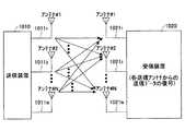
図14は、MIMO多重法を説明するための図であり、複数のアンテナを用いたMIMO通信システムの構成を示す図である。このシステムによれば、送信側の複数のアンテナ10111〜1011Nから各々異なった信号を同じ周波数を用いて送り、受信側においても複数のアンテナ10211〜1021Nを用いてそれら全てを同時に受信することにより、伝送帯域を増やさずに、送信アンテナ数に比例した伝送速度の高速化が可能である(例えば、非特許文献1参照)。FIG. 14 is a diagram for explaining the MIMO multiplexing method, and is a diagram illustrating a configuration of a MIMO communication system using a plurality of antennas. According to this system, different signals are transmitted from a plurality of antennas 10111 to 1011N on the transmission side using the same frequency, and all of them are received simultaneously using a plurality of antennas 10211 to 1021N on the reception side. By doing so, it is possible to increase the transmission speed in proportion to the number of transmission antennas without increasing the transmission band (see, for example, Non-Patent Document 1).
また、MIMOと総称される技術の1つにBLAST(Bell Labs Layered Space-Time)がある。BLASTは、異なる情報を複数の送信アンテナから同一周波数において同時に並列伝送し、受信側において干渉抑圧で制御されたダイバーシチ受信とレプリカ減算によって信号分離を行う方式である(例えば、非特許文献1参照)。 One of the technologies collectively referred to as MIMO is BLAST (Bell Labs Layered Space-Time). BLAST is a method in which different information is simultaneously transmitted from a plurality of transmitting antennas in parallel at the same frequency, and signal separation is performed by diversity reception controlled by interference suppression on the receiving side and replica subtraction (for example, see Non-Patent Document 1). .
上記の通り、MIMO多重法では高速の伝送速度を実現することが可能であるが、複数送信アンテナから異なるデータ系列が同一の周波数帯域、時間スロットで送信されるため、受信装置では受信信号から各送信アンテナから送信された送信信号系列を抽出する信号分離が復調のために必要となる。 As described above, with the MIMO multiplexing method, it is possible to realize a high transmission rate. However, since different data sequences are transmitted from a plurality of transmitting antennas in the same frequency band and time slot, the receiving device can receive each signal from the received signal. Signal separation for extracting a transmission signal sequence transmitted from a transmission antenna is necessary for demodulation.
MIMO多重における信号分離法については種々の方法が提案されている。例えば、最小平均自乗誤差法(MMSE)やZF(Zero Forcing)等の線形フィルタを用いた信号分離アルゴリズムは、送信アンテナ数と同じかそれよりも多い数の受信アンテナで受信した複数の受信信号を、着目する送信アンテナ以外の送信アンテナからの受信信号電力を抑圧するように合成する方法であり、受信側の演算量は比較的少なくてすむといった特徴がある。 Various methods for signal separation in MIMO multiplexing have been proposed. For example, a signal separation algorithm using a linear filter such as the least mean square error method (MMSE) or ZF (Zero Forcing) is used to obtain a plurality of received signals received by a number of receiving antennas equal to or greater than the number of transmitting antennas. This is a method of combining so as to suppress received signal power from transmission antennas other than the target transmission antenna, and has a feature that the amount of computation on the reception side can be relatively small.
また、最尤検出法(MLD)を用いた信号分離アルゴリズムは、各送信アンテナからの受信信号のレプリカ候補を生成し、受信信号と全送信アンテナからの受信信号のレプリカ候補の和とのユークリッド距離が最小になる受信信号レプリカを求めることで、最も確からしい各送信アンテナの送信信号系列を推定する方法であり、上記したMMSEに比較して、信号分離精度が高く、復調性能は優れるが、信号分離に要する演算量はアンテナ数に比例して指数的に増加するといった欠点がある。そこで、MLDにおける演算量を低減するために、QR分解を利用してMLDにおける2乗ユークリッド距離を計算する信号点候補を大幅に削減する方法が提案されている(例えば、非特許文献2参照)。 Further, the signal separation algorithm using the maximum likelihood detection method (MLD) generates a replica candidate of the received signal from each transmitting antenna, and the Euclidean distance between the received signal and the sum of the replica candidate of the received signal from all transmitting antennas. Is a method of estimating the most probable transmission signal sequence of each transmission antenna by obtaining a reception signal replica that minimizes the signal, and has higher signal separation accuracy and better demodulation performance than the above-described MMSE. There is a drawback that the amount of computation required for separation increases exponentially in proportion to the number of antennas. Therefore, in order to reduce the amount of computation in MLD, a method has been proposed in which the number of signal point candidates for calculating the square Euclidean distance in MLD is significantly reduced using QR decomposition (see, for example, Non-Patent Document 2). .
ところで、直接拡散(DS)CDMAは従来の情報データ変調信号を高速レートの拡散符号で拡散する2次変調を行って伝送することで複数の通信者が同一の周波数帯を用いて通信を行う方式であり、DS−CDMAを用いた無線通信では、信号伝送帯域幅の広帯域化により、マルチパスフェージング(周波数選択性フェージング)が生じ、送信信号は互いに伝搬遅延時間の異なる複数のマルチパスに分離されて受信される。 By the way, direct spread (DS) CDMA is a method in which a plurality of communicators communicate using the same frequency band by performing secondary modulation in which a conventional information data modulation signal is spread with a high-rate spread code. In wireless communication using DS-CDMA, multipath fading (frequency selective fading) occurs due to the widening of the signal transmission bandwidth, and the transmission signal is separated into a plurality of multipaths having different propagation delay times. Received.
DS−CDMAでの受信では、この複数のパスを合成するRake受信により受信品質を改善することができるが、異なるパス間には干渉(以下、マルチパス干渉という)が生じるため、Rake受信による受信品質改善がオフセットされる。 In the reception by DS-CDMA, the reception quality can be improved by the Rake reception that combines the plurality of paths. However, since interference occurs between different paths (hereinafter referred to as multipath interference), the reception by the Rake reception is performed. Quality improvement is offset.
上記マルチパス干渉は、拡散符号を乗算するスピードであるチップレートと情報シンボルのシンボルレートの比で定義される拡散率の逆数に大きさが比例する。このため、情報ビットレートを増大するために拡散率を1に近づけると、Rake受信効果よりもマルチパス干渉による受信品質の劣化のほうが支配的になり、高速データ伝送時に受信特性が劣化するという問題があった。そこで、このような問題を解決するために、マルチパス干渉キャンセラが提案されている(例えば、非特許文献3参照)。 The magnitude of the multipath interference is proportional to the reciprocal of the spreading factor defined by the ratio between the chip rate, which is the speed at which the spreading code is multiplied, and the symbol rate of the information symbol. For this reason, if the spreading factor is brought close to 1 in order to increase the information bit rate, the degradation of reception quality due to multipath interference becomes more dominant than the Rake reception effect, and the reception characteristics deteriorate during high-speed data transmission. was there. Therefore, in order to solve such a problem, a multipath interference canceller has been proposed (see, for example, Non-Patent Document 3).
このマルチパス干渉キャンセラは、非特許文献3に記載されているように、仮のRake受信結果で推定された送信信号系列と各受信パスのチャネル係数(伝搬路の複素包絡線)を基にパス毎の受信信号系列を推定し、受信信号からあるパス以外の全ての推定した受信信号系列を差し引くことを、パス数分繰り返すことで得られるマルチパス干渉を低減したパス毎の受信信号を用いて最終的なRake受信を行うことにより、マルチパス環境下での高品質受信を実現している。 As described in Non-Patent Document 3, this multipath interference canceller uses a path based on a transmission signal sequence estimated from a temporary Rake reception result and a channel coefficient (complex envelope of a propagation path) of each reception path. Using the received signal for each path that reduces multipath interference obtained by repeating the number of paths by estimating the received signal sequence for each path and subtracting all estimated received signal sequences other than a certain path from the received signal. By performing final Rake reception, high-quality reception in a multipath environment is realized.
また、DS−CDMAを用いた無線通信におけるMIMO多重でのマルチパス干渉の影響を低減する信号分離法として、他の送信アンテナからの受信信号により生じる干渉の抑圧とマルチパス干渉の抑圧を同時に行う2次元MMSEも提案されている。
ここで、DS−CDMAを用いた無線通信に情報ビットレートの高速化のために、上記したMIMO多重法を適用することを考えると、まず1送信アンテナあたりの情報ビットレートを増大するために拡散率を小さくしなければならない。この場合、図15に示すように、同一の受信タイミングのパス同士の送信アンテナ間の相互干渉(同図(a)参照)に加えて、全送信アンテナの異なる受信タイミングのマルチパスからのマルチパス干渉(同図(b)、(c)参照)が生じる。このため、受信側での信号分離の精度は、先に述べた1アンテナ送信時のRake受信と同様に、マルチパス干渉の影響で大きく劣化すると考えられる。 Here, considering that the MIMO multiplexing method described above is applied to wireless communication using DS-CDMA in order to increase the information bit rate, first, spreading is performed to increase the information bit rate per transmission antenna. The rate must be reduced. In this case, as shown in FIG. 15, in addition to the mutual interference between the transmission antennas of the paths having the same reception timing (see FIG. 15A), the multipath from the multipaths having different reception timings of all the transmission antennas. Interference occurs (see (b) and (c) in the figure). For this reason, it is considered that the accuracy of signal separation on the reception side is greatly deteriorated due to the influence of multipath interference, as in the case of Rake reception at the time of one-antenna transmission described above.
先に提案されたマルチパス干渉キャンセラでは、1アンテナからのみ信号が送信される場合の構成であり、MIMO多重時に適用しても、Rake受信では高精度な送信信号系列の推定ができない。 The previously proposed multipath interference canceller has a configuration in which a signal is transmitted from only one antenna, and even when applied during MIMO multiplexing, a highly accurate transmission signal sequence cannot be estimated by Rake reception.
また、図15から明らかなように、MIMO多重時におけるマルチパス干渉は同一送信アンテナからの干渉だけでなく、異なる送信アンテナからの受信信号からも生じるため、高精度な受信のためには、これらのマルチパス干渉も抑圧する必要がある。 Further, as is clear from FIG. 15, multipath interference at the time of MIMO multiplexing occurs not only from interference from the same transmission antenna but also from reception signals from different transmission antennas. It is also necessary to suppress multipath interference.
しかしながら、上記したMMSEは原理的にMLDに比較して信号分離精度が悪く、受信側で最適な性能が得られない。また、2次元MMSEにおいては、他の送信アンテナからの受信信号により生じる干渉の抑圧に加えて、マルチパス干渉も抑圧するようにフィルタ係数が制御されるため、信号分離精度の劣化がさらに大きくなるといった問題があった。 However, the above-mentioned MMSE is in principle poorer in signal separation accuracy than MLD, and optimal performance cannot be obtained on the receiving side. Further, in the two-dimensional MMSE, the filter coefficient is controlled so as to suppress multipath interference in addition to suppression of interference caused by a received signal from another transmitting antenna, so that the signal separation accuracy is further deteriorated. There was a problem.
本発明は、上記のような問題点に鑑みてなされたもので、その課題とするところは、マルチパス干渉による受信特性の劣化を抑圧して高精度な信号分離を実現することのできる受信装置、受信方法、および無線通信システムを提供することである。 The present invention has been made in view of the above-described problems, and a problem to be solved by the present invention is a receiving apparatus capable of realizing high-precision signal separation by suppressing deterioration of reception characteristics due to multipath interference. And a receiving method and a wireless communication system.
本発明は、CDMA方式を用いて信号の受信を行う受信装置において、M本(Mは、正の整数)の送信アンテナから送信された送信信号を、N本(Nは、正の整数)の受信アンテナにより受信しているであって、各受信アンテナで受信した受信信号を1次復調して各送信アンテナからの送信信号を推定し、推定結果に基づいてマルチパス環境における受信アンテナ毎の各パスの受信信号を再生するマルチパス受信信号再生手段と、前記各受信アンテナで受信した受信信号から着目するパス以外のパスの前記再生受信信号を減じるマルチパス干渉キャンセル手段と、前記減じた信号を用いて2次復調を行う復調手段と、を備えることを特徴の1つとしている。 The present invention provides a receiving apparatus that receives a signal using a CDMA system, and transmits N (N is a positive integer) transmission signals transmitted from M (M is a positive integer) transmission antennas. The reception signal received by each reception antenna is first demodulated to estimate the transmission signal from each transmission antenna, and each reception antenna in each multipath environment is estimated based on the estimation result. A multipath received signal reproducing means for reproducing a received signal of a path, a multipath interference canceling means for subtracting the reproduced received signal of a path other than the path of interest from the received signal received by each receiving antenna, and the reduced signal. And a demodulating means for performing secondary demodulation using one of the features.
また、前記受信装置であって、前記マルチパス受信信号再生手段は、前記1次復調を、最小平均自乗誤差法(MMSE: Minimum Mean Square Error)を用いて実行することを特徴としている。 Further, in the receiving apparatus, the multipath received signal reproducing means performs the primary demodulation using a minimum mean square error (MMSE) method.
また、前記受信装置であって、前記マルチパス受信信号再生手段は、前記1次復調を、最尤検出法(MLD: Maximum Likelihood Detention)を用いて実行することを特徴としている。 Further, in the receiving apparatus, the multipath received signal reproduction means performs the primary demodulation using a maximum likelihood detection method (MLD).
また、前記受信装置であって、前記マルチパス受信信号再生手段は、QR分解を利用した最尤検出法を用いて複数パスを一括して前記1次復調を実行することを特徴としている。 Further, in the receiving apparatus, the multipath received signal reproducing means is characterized in that the primary demodulation is performed collectively for a plurality of paths using a maximum likelihood detection method using QR decomposition.
また、前記受信装置であって、前記マルチパス受信信号再生手段は、QR分解を利用した最尤検出法を用いてパス毎に前記1次復調を実行することを特徴としている。 Further, in the receiving apparatus, the multipath received signal reproducing means performs the primary demodulation for each path using a maximum likelihood detection method using QR decomposition.
また、前記受信装置であって、前記マルチパス受信信号再生手段は、上記の方法を用いて推定される送信シンボル系列の確からしさに基づいて、受信信号の振幅を制御することを特徴としている。 In the receiving apparatus, the multipath received signal reproducing means controls the amplitude of the received signal based on the probability of the transmission symbol sequence estimated using the above method.
また、前記受信装置であって、前記マルチパス受信信号再生手段は、前記M本の送信アンテナから送信される既知のパイロット信号を用いてチャネル係数を推定することを特徴としている。 Further, in the receiving apparatus, the multipath received signal regenerating means estimates channel coefficients using known pilot signals transmitted from the M transmitting antennas.
また、前記受信装置であって、所定数の前記マルチパス受信信号再生手段及び前記マルチパス干渉キャンセル手段を多段接続することを特徴としている。 The receiving apparatus is characterized in that a predetermined number of the multipath received signal reproducing means and the multipath interference canceling means are connected in multiple stages.
また、前記受信装置であって、前記マルチパス受信信号再生手段が多段接続される場合に、各段において、前記マルチパス干渉キャンセル手段により減じられた信号を用いて、前記M本の送信アンテナから送信される既知のパイロット信号に基づいて推定されるチャネル係数推定値の更新を行うことを特徴としている。 Further, in the reception apparatus, when the multipath received signal regeneration means is connected in multiple stages, at each stage, the signals reduced by the multipath interference cancellation means are used to output from the M transmission antennas. The channel coefficient estimation value estimated based on the known pilot signal to be transmitted is updated.
また、前記受信装置であって、前記復調手段は、最尤検出法を用いて2次復調を行うことを特徴としている。 In the receiving apparatus, the demodulating means performs secondary demodulation using a maximum likelihood detection method.
また、前記受信装置であって、前記復調手段は、QR分解を利用した最尤検出法を用いて複数パスを一括して2次復調を行うことを特徴としている。 Further, in the receiving device, the demodulating unit performs secondary demodulation on a plurality of paths at once using a maximum likelihood detection method using QR decomposition.
また、前記受信装置であって、前記復調手段は、QR分解を利用した最尤検出法を用いてパス毎に2次復調を行うことを特徴としている。 Further, in the receiving apparatus, the demodulation means performs secondary demodulation for each path using a maximum likelihood detection method using QR decomposition.
また、前記受信装置であって、前記M本の送信アンテナから符号多重された送信信号が送信されたときに、前記マルチパス受信信号再生手段は、各受信アンテナで受信した受信信号を1次復調して拡散符号毎に受信アンテナ毎の各パスの受信信号を再生し、前記マルチパス干渉キャンセル手段は、前記各受信アンテナで受信した受信信号から着目するパス以外のパスの全ての拡散符号に対応する前記再生受信信号を減じた信号を生成し、前記復調手段は、前記減じた信号を用いて拡散符号毎に2次復調を行うことを特徴としている。 Further, in the receiving apparatus, when a transmission signal code-multiplexed from the M transmission antennas is transmitted, the multipath reception signal regeneration means performs primary demodulation on the reception signal received by each reception antenna. Then, the reception signal of each path for each receiving antenna is reproduced for each spreading code, and the multipath interference canceling means supports all spreading codes of paths other than the path of interest from the received signal received by each receiving antenna. A signal obtained by subtracting the reproduced reception signal to be generated is generated, and the demodulating means performs secondary demodulation for each spreading code using the reduced signal.
本発明の実施例によれば、CDMA方式を用いて複数の送信アンテナから異なるデータを同時送信したときに、マルチパス干渉を低減し、異なる送信アンテナから送信された信号の高精度な分離を実現することができる。その結果、マルチパスフェージング環境における、受信品質を大幅に向上させることができる。 According to the embodiment of the present invention, when different data is simultaneously transmitted from a plurality of transmission antennas using a CDMA system, multipath interference is reduced and high-accuracy separation of signals transmitted from different transmission antennas is realized. can do. As a result, reception quality in a multipath fading environment can be greatly improved.
1 無線通信システム
10,1010 送信装置
111〜11m,10111〜1011n 送信アンテナ
20,200,600,1020 受信装置
211〜21n,10211〜1021n 受信アンテナ
22,30〜50,70,211〜213,611〜614 マルチパス受信信号再生部
23,2211,2212,2221,2222,2231,2232,615〜618 マルチパス干渉キャンセル部
24,300,400,500,621,622 復調部
31,41,51,71,100,311,411,511 チャネル係数推定部
32 線形フィルタ係数計算部
33 線形フィルタリング部
341〜34m,42〜45,52〜55,72〜75,312〜315,412〜415,512〜515 逆拡散部
351〜35m 送信シンボル系列推定部
361〜36m,501〜50m,621〜62m,841〜84m マルチパス受信信号再生処理部
46,58,80,316,418,520 送信シンボル候補生成部
47,317 受信信号レプリカ生成部
48,60,82,318,420,522 尤度計算部
491〜49m,611〜61m,831〜83m 送信シンボル系列推定部
56,76,77,416,516,517 QR分解部
57,78,79,417,518,519 QH演算部
59,81,419,521 変換信号レプリカ生成部
101〜104 相関検出部
111〜114 レプリカ信号生成部
319,421,523 送信系列推定部
631〜634,641〜644 加算器1 wireless communication system 10,1010 transmitting apparatus11 1 ~11 m, 1011 1 ~1011 n transmit antennas 20,200,600,1020 receiving apparatus21 1 ~21 n, 1021 1 ~1021 n receiving antennas 22,30~50, 70, 211 to 213, 611 to 614 Multipath reception signal regeneration units 23, 2211 , 2212 , 2221 , 2222 , 2231 , 2232 , 615 to 618 Multipath interference cancellation unit 24, 300, 400, 500 , 621, 622 Demodulator 31, 41, 51, 71, 100, 311, 411, 511 Channel coefficient estimator 32 Linear filter coefficient calculator 33 Linear filtering unit 341 to 34m , 42 to 45, 52 to 55, 72 ~ 75,312-315,412-415,512-515 Despreading part 351 to 35m transmission symbol sequence estimation units 361 to 36m , 501 to 50m , 621 to 62m , 841 to 84m multipath received signal reproduction processing units 46, 58, 80, 316, 418, 520 Transmission symbol candidate generation unit 47, 317 Reception signal replica generation unit 48, 60, 82, 318, 420, 522 Likelihood calculation unit 491 to 49m , 611 to 61m , 831 to 83m Transmission symbol sequence estimation parts 56,76,77,416,516,517 QR decomposition unit 57,78,79,417,518,519 QH calculation section 59,81,419,521 conversion signal replica generating unit 101 through 104 correlation detecting unit 111 to 114 Replica Signal Generation Units 319, 421, 523 Transmission Sequence Estimation Units 631-634, 641-644 Adder
以下、本発明の実施の形態を図面に基づいて説明する。 Hereinafter, embodiments of the present invention will be described with reference to the drawings.
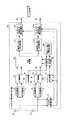
図1は、本発明の実施の形態に係る受信装置を含んで構成される無線通信システム1を示す図である。本発明に係る無線通信システム1は、DS−CDMAにおけるMIMOチャネルまたはMISO(Multi-Input Single-Output、複数入力単出力、つまり、受信装置の受信アンテナが1つ)チャネル用いたシステムであり、本実施形態では、MIMOチャネルを用いて信号伝送がなされる場合を例にとり、以下説明する。 FIG. 1 is a diagram showing a
同図において、この無線通信システム1は、送信装置10と受信装置20が無線通信において接続可能となっている。送信装置10は、入力される送信データビット系列をM本の送信系列にシリアル・パラレル変換し、同一の周波数帯かつ同一の拡散符号を用いてデータ変調を行い、送信信号としてM本の送信アンテナ111〜11mから同時に送信する。このようにして送信された送信信号はマルチパス伝搬路を経てL個のマルチパス受信信号となって受信装置20に具備されるN本の受信アンテナ211〜21nで受信される。受信装置20は、N本の受信アンテナ211〜21nと、マルチパス受信信号再生部22と、N個のマルチパス干渉キャンセル部231〜23nと、復調部24とを具備して構成される。In this figure, in this
ここで、送信装置10の送信アンテナmから送信された送信信号をSm(t)とすると、受信装置20の受信アンテナnで受信される受信信号rn(t)は、次式で表すことができる。Here, when the transmission signal transmitted from the transmission antenna m of the

次に、本発明に係る受信装置20の動作を説明する。 Next, the operation of the receiving
受信装置20では、N本の受信アンテナ211〜21nで受信された受信信号rn(t)が、マルチパス受信信号再生部22に入力される。マルチパス受信信号再生部22では、N本の受信アンテナ211〜21nで受信された受信信号を基に、仮の信号分離(1次復調という)を行うことで、受信アンテナ211〜21nごとに各送信アンテナ111〜11mからの受信パス毎の受信信号系列In the receiving
次に、受信アンテナ211〜21n数分の各マルチパス干渉キャンセル部231〜23nでは、当該受信アンテナ211〜21nの受信信号と、各送信アンテナ111〜11mからの受信パス毎の受信信号系列を入力とし、受信信号から他のパスの受信信号全てを差し引いたマルチパス干渉キャンセル後の受信信号rn,l(t)を次式にしたがって演算し、出力する。Next, the receiving
このように本実施形態によれば、マルチパス受信信号再生部で、1次復調が行われ、送信信号が推定される。そして、その推定された送信信号とチャネル変動値(チャネル係数)とを掛け合わせることでパス毎の受信信号を推定し、マルチパス干渉キャンセル部で、受信信号から着目するパス以外の推定した受信信号が減算される。これにより、復調部では、マルチパス干渉を除去した後の受信信号を用いて復調することが可能となり、高精度に信号分離を行うことができる。 As described above, according to the present embodiment, the multipath received signal reproduction unit performs primary demodulation and estimates a transmission signal. Then, the received signal for each path is estimated by multiplying the estimated transmission signal and the channel fluctuation value (channel coefficient), and the multipath interference canceling unit estimates the received signal other than the path of interest from the received signal. Is subtracted. As a result, the demodulator can perform demodulation using the received signal after removing the multipath interference, and can perform signal separation with high accuracy.
すなわち、上りリンクにDS−CDMA方式を用い、MIMO多重法を適用した場合であっても、マルチパス干渉に起因した信号分離精度の劣化を回避することができる。 That is, even when the DS-CDMA scheme is used for the uplink and the MIMO multiplexing method is applied, it is possible to avoid degradation of signal separation accuracy due to multipath interference.
図2は、図1に示すマルチパス受信信号再生部の第1の実施形態を示す構成図である。本実施形態では、マルチパス受信信号再生部は、1次復調方法としてMMSEアルゴリズムを用いる。 FIG. 2 is a block diagram showing a first embodiment of the multipath received signal reproducing unit shown in FIG. In this embodiment, the multipath received signal regeneration unit uses the MMSE algorithm as the primary demodulation method.
同図において、このマルチパス受信信号再生部30は、チャネル係数推定部31と、線形フィルタ係数計算部32と、線形フィルタリング部33と、M個の逆拡散部341〜34mと、M個の送信シンボル系列推定部351〜35mと、M個のマルチパス受信信号再生処理部361〜36mとから構成される。In this figure, this multipath received
本実施形態におけるマルチパス受信信号再生部30では、最初に、チャネル係数推定部31において、N本の受信アンテナ211〜21nで受信された受信信号rn(t)を入力し、受信アンテナ211〜21nと送信アンテナ111〜11n(図1参照)との間各々の各パスのチャネル係数hm,n,lが推定される。In the multipath received
次に、線形フィルタ係数計算部32において線形フィルタの係数計算、及びその求めた線形フィルタ係数を用いた等化のためのフィルタリング処理が行われる。これらの処理は、時間領域の信号処理で実現する方法と、周波数領域の信号処理で実現する方法とが考えられるが、以下では、周波数領域で信号処理を行う方法について例を挙げて説明する。 Next, the linear filter
線形フィルタ係数計算部32では、得られたチャネル係数の推定値 In the linear filter
次に、上記のようにして求められたチャネルのインパルス応答に対して、線形フィルタリングするブロックサイズに相当するチップ数×オーバサンプリング数分の大きさとなるNfポイントのFFTを行うことで、送信アンテナ111〜11mからの送信信号の受信アンテナ211〜21nでのチャネル変動値の周波数成分であるThen, by performing relative channel impulse response obtained as described above, the number of chips × oversampling number of which corresponds to the block size for linear filtering the FFT size to become Nf points, the transmitting antenna 11 is a frequency component of a channel fluctuation value at the receiving
線形フィルタの係数は、ZF基準あるいはMMSE基準にしたがって求めることができる。 The coefficients of the linear filter can be obtained according to the ZF criterion or the MMSE criterion.
例えば、ZF基準の線形フィルタの係数は、次式により求めることができる. For example, the coefficient of the linear filter based on ZF can be obtained by the following equation.
次に、線形フィルタリング部33では、NfポイントのFFTにより、N系列の受信信号それぞれを周波数領域の受信信号Y(f)に変換する。その後、周波数領域の受信信号Y(f)にW(f)を乗算することにより、周波数領域のチャネル変動によるコードチャネル間の直交性の崩れ(時間領域で見たMPII(Multi-Path-Interference))と送信アンテナ間の干渉を同時に等化(抑圧)したM個の送信信号の推定値Next, the
例えば、送信シンボル系列推定部351〜35mにおいて硬判定を行う場合の実施例は以下のようになる。For example, an example in which a hard decision is performed in the transmission symbol
ここで、送信シンボルdm,i(iはシンボル候補番号Here, transmission symbol dm, i (i is a symbol candidate number)
また、送信シンボル系列推定部351〜35mにおいて軟判定を行う場合の実施例は以下のようになる。An example in which soft decision is performed in the transmission
まず、次式にしたがって、軟判定のビット系列を求める。 First, a soft decision bit sequence is obtained according to the following equation.
は、雑音電力を表す。
Represents noise power.
軟判定シンボル Soft decision symbol
図3は、マルチパス受信信号再生部の第2の実施形態を示す構成図である。本実施形態では、マルチパス受信信号再生部は、1次復調方法としてMLDアルゴリズムを用いる。 FIG. 3 is a configuration diagram illustrating a second embodiment of the multipath received signal reproducing unit. In the present embodiment, the multipath received signal reproduction unit uses the MLD algorithm as the primary demodulation method.
同図において、このマルチパス受信信号再生部40は、チャネル係数推定部41と、N×L個の逆拡散部42〜45と、送信シンボル候補生成部46と、受信信号レプリカ生成部47と、尤度計算部48と、M個の送信シンボル系列推定部491〜49mと、M個のマルチパス受信信号再生処理部501〜50mとから構成される。In this figure, the multipath received
本実施形態におけるマルチパス受信信号再生部40では、最初に、チャネル係数推定部41において、N本の受信アンテナ211〜21nで受信された受信信号rn(t)を入力し、受信アンテナ211〜21nと送信アンテナ111〜11nとの間各々の各パスのチャネル係数hm,n,lが推定される。In the multipath received
次に、N×L個の逆拡散部42〜45により、N本の受信アンテナ211〜21nで受信された受信信号rn(t)を送信時に用いた拡散符号と同一の拡散符号で各パスの受信タイミングで逆拡散し、N×L個の各受信アンテナでの各パスの逆拡散信号zn,lを求める。Next, the N ×
送信シンボル候補生成部46は、各送信アンテナに対する送信シンボルdm,i(iはシンボル候補番号The transmission symbol
受信信号レプリカ生成部47は、送信シンボル候補生成部46で生成された送信シンボルと、チャネル係数推定部41で推定されたチャネル係数とを入力して受信信号レプリカ The reception signal
まず、次式にしたがって、軟判定のビット系列を求める。 First, a soft decision bit sequence is obtained according to the following equation.
軟判定シンボル Soft decision symbol
受信アンテナごとに各送信アンテナからの受信パス毎の受信信号系列
Receive signal sequence for each receive path from each transmit antenna for each receive antenna
同図において、このマルチパス受信信号再生部50は、チャネル係数推定部51と、N×L個の逆拡散部52〜55と、QR分解部56と、QH演算部57と、送信シンボル候補生成部58と、変換信号レプリカ生成部59と、尤度計算部60と、M個の送信シンボル系列推定部611〜61mと、M個のマルチパス受信信号再生処理部621〜62mとから構成される。In the figure, the multipath receiving
本実施形態におけるマルチパス受信信号再生部50では、最初に、チャネル係数推定部51において、N本の受信アンテナ211〜21nで受信された受信信号rn(t)を入力し、受信アンテナ211〜21nと送信アンテナ111〜11nとの間各々の各パスのチャネル係数hm,n,lが推定される。In the multipath received
次に、N×L個の逆拡散部52〜55により、N本の受信アンテナ211〜21nで受信された受信信号rn(t)を送信時に用いた拡散符号と同一の拡散符号で各パスの受信タイミングで逆拡散し、N×L個の各受信アンテナでの各パスの逆拡散信号zn,lを求める。Next, N ×
次に、QR分解部56では、チャネル係数からなる下記のM行×(N×L)列のチャネル行列を生成し、チャネル行列のQR分解を行って、Q行列およびR行列を出力する。 Next, the
ここで、Hは共役複素転置を表し、Iは単位行列を表す。また、R行列はM行×M列の上三角行列となる。 Here, H represents a conjugate complex transpose, and I represents a unit matrix. The R matrix is an upper triangular matrix of M rows × M columns.
QH演算部部57では、次式にしたがった演算が行われる。In QH calculation section 57 performs a calculation according to the following equation is performed.
次に、送信シンボル候補生成部58は、送信アンテナM−1に対する送信シンボル Next, the transmission symbol
変換信号レプリカ生成部59は、送信アンテナMに対応するSM個の送信シンボル系列と送信アンテナM−1に対する送信シンボルとからR行列を入力として変換信号レプリカThe converted signal
同様にして、送信シンボル候補生成部58は、送信アンテナmに対する送信シンボルdm,iを生成して出力する。変換信号レプリカ生成部59は、送信アンテナm+1から、送信アンテナMに対応するSm+1個の送信シンボル系列と送信アンテナmに対する送信シンボルとR行列を入力として変換信号レプリカSimilarly, transmission symbol
以上の操作を繰り返すことにより、得られたC・S2個の全送信アンテナに対応する送信シンボル系列の組み合わせBy repeating the above operation, combinations of transmission symbol sequences corresponding to all C · S2 transmission antennas obtained are obtained.
送信シンボル系列推定部611〜61mでは、各送信アンテナに対応する、生き残り送信シンボルとそれに対応する誤差信号とを入力とし、最小誤差を選択し、当該誤差を与える送信シンボル系列を推定する。In the transmission symbol sequence estimation units 611 to 61m , the surviving transmission symbol corresponding to each transmission antenna and the corresponding error signal are input, the minimum error is selected, and the transmission symbol sequence that gives the error is estimated.
送信シンボル系列推定部611〜61mにおいて硬判定を行う場合の実施例は以下のようになる。An example in which a hard decision is performed in the transmission symbol sequence estimation units 611 to 61m is as follows.
まず、次式にしたがって、軟判定のビット系列を求める。 First, a soft decision bit sequence is obtained according to the following equation.
軟判定シンボル Soft decision symbol
図5は、マルチパス受信信号再生部の第4の実施形態を示す構成図である。本実施形態では、マルチパス受信信号再生部は、1次復調方法としてパス毎に処理を行うMLDアルゴリズムを用いる。 FIG. 5 is a configuration diagram illustrating a fourth embodiment of the multipath received signal reproducing unit. In the present embodiment, the multipath received signal reproduction unit uses an MLD algorithm that performs processing for each path as the primary demodulation method.
同図において、このマルチパス受信信号再生部70は、チャネル係数推定部71と、N×L個の逆拡散部72〜75と、L個のQR分解部76、77と、L個のQH演算部78、79と、送信シンボル候補生成部80と、変換信号レプリカ生成部81と、尤度計算部82と、M個の送信シンボル系列推定部831〜83mと、M個のマルチパス受信信号再生処理部841〜84mとから構成される。In the figure, the multipath received
本実施形態におけるマルチパス受信信号再生部70では、最初に、チャネル係数推定部71において、N本の受信アンテナ211〜21nで受信された受信信号rn(t)を入力し、受信アンテナ211〜21nと送信アンテナ111〜11nとの間各々の各パスのチャネル係数hm,n,lが推定される。In the multipath received
次に、N×L個の逆拡散部72〜75により、N本の受信アンテナ211〜21nで受信された受信信号rn(t)を送信時に用いた拡散符号と同一の拡散符号で各パスの受信タイミングで逆拡散し、N×L個の各受信アンテナでの各パスの逆拡散信号zn,lを求める。Next, the N ×
次に、第l番目のQR分解部では、第l番目のパスのチャネル係数からなる下記のチャネル行列をパス数分生成し、それぞれ、チャネル行列のQR分解を行って、Q行列およびR行列を出力する。 Next, the l-th QR decomposition unit generates the following channel matrix composed of the channel coefficients of the l-th path for the number of paths, performs QR decomposition of the channel matrix, respectively, and converts the Q matrix and R matrix into Output.
したがって、第l番目のQH演算部における演算は、Therefore, the calculation in the l-th QH calculation unit is
送信シンボル候補生成部80は、まず、送信アンテナMに対する送信シンボルdM,iを生成して変換信号レプリカ生成部81に出力する。変換信号レプリカ生成部81は、送信シンボルdM,iと、Rl行列を入力して、変換信号レプリカFirst, transmission symbol
送信シンボルとそれに対応する誤差信号とを入力とし、誤差の小さいSM個の送信アンテナMに対応する送信シンボル系列
次に、送信シンボル候補生成部80は、送信アンテナM−1に対する送信シンボル Next, transmission symbol
変換信号レプリカ生成部81は、送信アンテナMに対応するSM個の送信シンボル系列と送信アンテナM−1に対する送信シンボルとからR行列を入力として変換信号レプリカThe converted signal replica generation unit 81 receives the R matrix from the SM transmission symbol sequences corresponding to the transmission antenna M and the transmission symbols for the transmission antenna M-1, and receives the converted signal replica.
同様にして、送信シンボル候補生成部80は、送信アンテナmに対する送信シンボルdm,iを生成して出力する。変換信号レプリカ生成部81は、送信アンテナm+1から、送信アンテナMに対応するSm+1個の送信シンボル系列と送信アンテナmに対する送信シンボルとR行列を入力として変換信号レプリカSimilarly, the transmission symbol
以上の操作を繰り返すことにより、得られたC・S2個の全送信アンテナに対応する送信シンボル系列の組み合わせBy repeating the above operation, combinations of transmission symbol sequences corresponding to all C · S2 transmission antennas obtained are obtained.
送信シンボル系列推定部831〜83mでは、各送信アンテナに対応する、生き残り送信シンボルとそれに対応する誤差信号とを入力とし、最小誤差を選択し、当該誤差を与える送信シンボル系列を推定する。Transmission symbol sequence estimators 831 to 83m each input a surviving transmission symbol corresponding to each transmission antenna and the corresponding error signal, select a minimum error, and estimate a transmission symbol sequence that gives the error.
送信シンボル系列推定部831〜83mにおいて硬判定を行う場合の実施例は以下のようになる。An example in which a hard decision is performed in the transmission symbol sequence estimation units 831 to 83m is as follows.
まず、次式にしたがって、軟判定のビット系列を求める。 First, a soft decision bit sequence is obtained according to the following equation.
軟判定シンボル Soft decision symbol
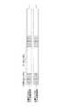
図6は、本発明に係るチャネル係数推定部の構成図であり、図7Aおよび図7Bは、当該チャネル係数推定部を用いる場合の送信装置より送信される送信信号の構成例を示す図である。 FIG. 6 is a configuration diagram of a channel coefficient estimator according to the present invention, and FIGS. 7A and 7B are diagrams illustrating a configuration example of a transmission signal transmitted from a transmission apparatus when the channel coefficient estimator is used. .
まず、図7Aおよび図7Bを参照しながら、送信装置から送信される送信信号について説明する。同図に示されるように、本実施形態では、各送信アンテナ(ここでは、送信アンテナ1、2)からの送信信号に、送信アンテナ毎に異なる4シンボル長のパイロットシンボル(斜線部)がデータシンボルに対して周期的に挿入されている。図7Aに示される例では、各送信アンテナのパイロットシンボルパターンは互いに直交している。 First, a transmission signal transmitted from the transmission apparatus will be described with reference to FIGS. 7A and 7B. As shown in the figure, in this embodiment, pilot symbols (shaded portions) having different 4-symbol lengths for each transmission antenna are data symbols in transmission signals from the transmission antennas (here,
また、図7Bに示される例では、各送信アンテナのパイロットシンボルの拡散に用いられる拡散符号(C1、C2)が直交している。 In the example shown in FIG. 7B, the spreading codes (C1, C2) used for spreading the pilot symbols of the transmitting antennas are orthogonal.
パイロット信号の送信は、図7A、図7Bのいずれかの方法によって行えばよく、送信アンテナ間のパイロット信号を直交させることで高精度なチャネル推定が可能となる。上記のような直交シンボルパターンもしくは直交拡散符号は、例えば、パイロットシンボル数と同じ長さもしくは、パイロットシンボルの拡散率と同じ長さのWalsh系列を用いることで生成可能である。これ以降、送信アンテナmのパイロット信号系列をpm(n)として説明を進める。なお、nはチップ番号を表すものとする。The pilot signal may be transmitted by any one of the methods shown in FIGS. 7A and 7B. By making the pilot signals between the transmitting antennas orthogonal, channel estimation with high accuracy is possible. The orthogonal symbol pattern or the orthogonal spreading code as described above can be generated by using, for example, a Walsh sequence having the same length as the number of pilot symbols or the same length as the spreading factor of the pilot symbols. Hereinafter, the description will be made assuming that the pilot signal sequence of the transmission antenna m is pm (n). Note that n represents a chip number.
図6に戻り、本発明に係るチャネル係数推定部の構成を説明する。このチャネル係数推定部100は、送信アンテナmと受信アンテナn間の各パスのチャネル係数を推定する機能を備える。本例では、3送信アンテナ、4受信アンテナの場合のチャネル係数推定部の構成例を示している。すなわち、このチャネル係数推定部は、3×4の相関検出部101〜104と、パイロット信号レプリカ生成部111〜114とを備える。なお、本例では、構成要素が複数有る相関検出部と、パイロット信号レプリカ生成部の符号の末尾に連番を付すものとして図示した。 Returning to FIG. 6, the configuration of the channel coefficient estimation unit according to the present invention will be described. The channel
まず、同図を参照しながら送信アンテナ1と受信アンテナ1間のチャネル係数h1,1,lを推定する場合の動作を説明する。First, the operation for estimating the
同図において、受信アンテナ1で受信された受信信号r1は相関検出部101に入力される。また、パイロット信号レプリカ生成部111では送信アンテナ1のパイロットシンボル系列p1を生成し、相関検出部101に入力する。 In the figure, the received
相関検出部101では、受信信号r1に送信アンテナ1のパイロットシンボル系列p1の複素共役値をパスlの受信タイミングを考慮して乗算した値を4パイロットシンボル区間で平均化することにより送信アンテナ1と受信アンテナ1間のチャネル係数h1,1,lを次式にしたがって推定し出力する。
同様にして、受信信号r1を入力とする2段目の相関検出部(図示省略)では、受信信号r1と2段目のパイロットシンボルレプリカ生成部(図示省略)で生成された送信アンテナmのパイロットシンボル系列pmを入力として、チャネル係数h1,m,lを推定し出力する。Similarly, the correlation detection unit of the second stage for receiving the reception signal r1 at (not shown), the received signal r1 and second-stage pilot symbol replica generating unit of the transmitting antenna m generated by the (not shown) as input pilot symbol sequencep m, the channel coefficientsh 1, m, estimates thel outputs.
さらに同様にして、受信信号r4とパイロットシンボルレプリカ生成部113で生成される送信アンテナ1のパイロットシンボル系列p1を相関検出部103に入力し、相関を求めることでチャネル係数h4,1,lを推定し出力する。Further, similarly, the received signal r4 and the pilot symbol sequence p1 of the
以上の動作を繰り返すことで、3送信アンテナと4受信アンテナ間の各パスのチャネル係数を推定することができる。なお、上記では、パイロットシンボルがデータシンボルに時間的に多重される構成を例にあげて説明したが、符号多重を用いた場合も同様の方法でチャネル係数推定値を得ることができる。 By repeating the above operation, the channel coefficient of each path between the three transmitting antennas and the four receiving antennas can be estimated. In the above description, the configuration in which pilot symbols are temporally multiplexed onto data symbols has been described as an example. However, even when code multiplexing is used, a channel coefficient estimation value can be obtained by the same method.
図8は、本発明の実施形態に係る受信装置の第2の実施形態を示す構成図である。同図に示すように本実施形態では、受信装置200は、複数のマルチパス受信信号再生部211〜213がシリアルにマルチパス干渉キャンセル部2211、2212、2221、2222、2231、2232を介して接続されており(本例では、3段構成)、最終段に復調部231が配置されている。初段のマルチパス受信信号再生部211には、上述した図2から図5に記載のいずれか任意のマルチパス受信信号再生部の構成を適用することができる。FIG. 8 is a block diagram showing a second embodiment of the receiving apparatus according to the embodiment of the present invention. As shown in the figure, in the present embodiment, the receiving
また、2段目以降のマルチパス受信信号再生部212、213にも、以上で説明した図2から図5に記載のいずれか任意のマルチパス受信信号再生部の構成を適用することができる。ここで、2段目以降の第p段目のマルチパス受信信号再生部への入力信号 Also, any of the configurations of the multipath received signal reproducing units described in FIGS. 2 to 5 described above can be applied to the second and subsequent multipath received
また、この構成を用いた場合は、2段目以降の第p段目のマルチパス受信信号再生部におけるチャネル係数推定部(図示省略)では、チャネル係数h11lの推定において、受信信号rn(t)の代わりにマルチパス干渉キャンセル後の受信信号When this configuration is used, the channel coefficient estimator (not shown) in the second and subsequent p-th multipath received signal regenerators receives the received signal rn (in the estimation of the channel coefficient h11l. Received signal after canceling multipath interference instead of t)
このように本実施形態によれば、マルチパス受信信号再生部を複数段設けることで、後段のマルチパス受信信号再生部では、マルチパス干渉キャンセル後の受信信号を用いて高精度にチャネル推定、送信シンボル系列推定を行うことができ、結果としてより高精度な受信アンテナごとの各送信アンテナからの受信パス毎の受信信号系列 As described above, according to the present embodiment, by providing a plurality of multipath reception signal regeneration units, the subsequent multipath reception signal regeneration unit performs channel estimation with high accuracy using the received signal after multipath interference cancellation, Transmission symbol sequence estimation can be performed, and as a result, a more accurate received signal sequence for each reception path from each transmission antenna for each reception antenna
図9は、本発明の実施形態に係る受信装置で用いられる復調部の第1の実施形態を示す構成図である。本実施形態では、復調部は、復調アルゴリズムとしてMLDを用いる。 FIG. 9 is a configuration diagram illustrating a first embodiment of a demodulation unit used in the reception device according to the embodiment of the present invention. In this embodiment, the demodulator uses MLD as a demodulation algorithm.
同図において、この復調部300は、チャネル係数推定部311と、N×L個の逆拡散部312〜315と、送信シンボル候補生成部316と、受信信号レプリカ生成部317と、尤度計算部318と、送信系列推定部319とから構成される。なお、構成要素が複数有る場合には、末尾に連番を付すものとして図示した。 In this figure, the
上記のように構成された復調部300の動作について説明する。 The operation of the
復調部300に入力される入力信号は、N×L個のマルチパス干渉キャンセル後の受信信号 The input signal input to the
さらに、N×L個のマルチパス干渉キャンセル後の受信信号 Further, N × L received signals after canceling multipath interference
上述したビット尤度は、チャネル復号器(例えば、ターボ復号器)等に入力されて最終的に情報ビット系列が復元される。 The bit likelihood described above is input to a channel decoder (for example, a turbo decoder) and the information bit sequence is finally restored.
図10は、本発明の実施形態に係る復調部の第2の実施形態を示す構成図である。本実施形態では、復調部は、復調アルゴリズムとしてパス一括で処理を行うMLDを用いる。 FIG. 10 is a block diagram showing a second embodiment of the demodulator according to the embodiment of the present invention. In the present embodiment, the demodulation unit uses an MLD that performs processing in a batch of paths as a demodulation algorithm.
同図において、この復調部400は、チャネル係数推定部411と、N×L個の逆拡散部412〜415と、QR分解部416と、QH演算部417と、送信シンボル候補生成部418と、変換信号レプリカ生成部419と、尤度計算部420と、送信系列推定部421とから構成される。なお、構成要素が複数有る場合には、末尾に連番を付すものとして図示した。In the figure, the
上記のように構成された復調部400の動作について以下説明する。 The operation of the
復調部400に入力される入力信号は、N×L個のマルチパス干渉キャンセル後の受信信号 The input signal input to the
さらに、N×L個のマルチパス干渉キャンセル後の受信信号 Further, N × L received signals after canceling multipath interference
次に、QR分解部416では、チャネル係数からなる下記のチャネル行列を生成し、チャネル行列のQR分解を行って、Q行列およびR行列をQH演算部417に出力する。Next,
送信シンボル候補生成部418は、まず、送信アンテナMに対する送信シンボルdM,jを生成して出力する。変換信号レプリカ生成部419は、送信シンボルdM,jとR行列を入力して変換信号レプリカFirst, transmission symbol
変換信号レプリカ生成部419は、送信アンテナMに対応するSM個の送信シンボル系列と送信アンテナM−1に対する送信シンボルとからR行列を入力として変換信号レプリカThe converted signal
同様にして、送信シンボル候補生成部418は、送信アンテナmに対する送信シンボルdm,iを生成して出力する。変換信号レプリカ生成部419は、送信アンテナm+1から、送信アンテナMに対応するSm+1個の送信シンボル系列と送信アンテナmに対する送信シンボルとR行列を入力として変換信号レプリカSimilarly, transmission symbol
以上の操作を繰り返すことにより、得られたC・S2個の全送信アンテナに対応する送信シンボル系列の組み合わせBy repeating the above operation, combinations of transmission symbol sequences corresponding to all C · S2 transmission antennas obtained are obtained.
送信系列推定部421では、各送信アンテナに対応する、生き残り送信シンボルとそれに対応する誤差信号とを入力とし、送信シンボル系列によって送信されたビットに対する尤度λiを出力する。なお、誤差信号に基づいたビット尤度の計算法は、既存のいかなる方法も適用可能である。The transmission sequence estimation unit 421 inputs the surviving transmission symbol corresponding to each transmission antenna and the corresponding error signal, and outputs the likelihood λi for the bits transmitted by the transmission symbol sequence. Note that any existing method can be applied to the bit likelihood calculation method based on the error signal.
上述したビット尤度はチャネル復号器(例えば、ターボ復号器)等に入力されて最終的に情報ビット系列が復元される。 The bit likelihood described above is input to a channel decoder (for example, a turbo decoder) and the information bit sequence is finally restored.
以上のように、第2の実施形態に係る復調部の構成(図10)は、図9において説明した第1の実施形態の復調部の構成に比較にして、若干のビット尤度の推定精度の劣化を許容すれば、誤差演算の回数をCM回からAs described above, the configuration of the demodulator according to the second embodiment (FIG. 10) is slightly more accurate than the configuration of the demodulator according to the first embodiment described in FIG. if allowed to deterioration, the number of the error calculation from the CM times
図11は、本発明の実施形態に係る復調部の第3の実施形態を示す構成例図である。本実施形態では、復調部は、復調アルゴリズムとしてパス毎に処理を行うMLDを用いる。 FIG. 11 is a configuration example diagram illustrating a third embodiment of the demodulation unit according to the embodiment of the present invention. In the present embodiment, the demodulation unit uses an MLD that performs processing for each path as a demodulation algorithm.
同図において、この復調部500は、チャネル係数推定部511と、N×L個の逆拡散部512〜515と、L個のQR分解部516、517と、L個のQH演算部518、519と、送信シンボル候補生成部520と、変換信号レプリカ生成部521と、尤度計算部522と、送信系列推定部523とから構成される。なお、構成要素が複数有る場合には、末尾に連番を付すものとして図示した。In this figure, the
上記のように構成された復調部500の動作について以下説明する。 The operation of the
復調部500に入力される入力信号は、N×L個のマルチパス干渉キャンセル後の受信信号 The input signal input to
される(なお、構成の簡単化のために、前段のマルチパス受信信号再生部におけるチャネル係数を用いることも同様に可能である)。
さらに、N×L個のマルチパス干渉キャンセル後の受信信号 Further, N × L received signals after canceling multipath interference
次に、第l番目のQR分解部では、第l番目のパスのチャネル係数からなる下記のチャネル行列をパス数分生成し、それぞれ、チャネル行列のQR分解を行って、Q行列およびR行列を出力する。 Next, the l-th QR decomposition unit generates the following channel matrix composed of the channel coefficients of the l-th path for the number of paths, performs QR decomposition of the channel matrix, respectively, and converts the Q matrix and R matrix into Output.
したがって、第l番目のQH演算部における演算は、Therefore, the calculation in the l-th QH calculation unit is
送信シンボル候補生成部520は、まず、送信アンテナMに対する送信シンボルdM,iを生成して変換信号レプリカ生成部521に出力する。変換信号レプリカ生成部521は、送信シンボルdM,iと、Rl行列を入力して、変換信号レプリカFirst, transmission symbol
次に、送信シンボル候補生成部520は、送信アンテナM−1に対する送信シンボルdM−1,iを生成して出力する。Next, transmission symbol
変換信号レプリカ生成部521は、送信アンテナMに対応するSM個の送信シンボル系列と送信アンテナM−1に対する送信シンボルとからR行列を入力として変換信号レプリカThe converted signal
同様にして、送信シンボル候補生成部520は、送信アンテナmに対する送信シンボルdm,iを生成して出力する。変換信号レプリカ生成部521は、送信アンテナm+1から、送信アンテナMに対応するSm+1個の送信シンボル系列と送信アンテナmに対する送信シンボルとR行列を入力として変換信号レプリカSimilarly, transmission symbol
以上の操作を繰り返すことにより、得られたC・S2個の全送信アンテナに対応する送信シンボル系列の組み合わせBy repeating the above operation, combinations of transmission symbol sequences corresponding to all C · S2 transmission antennas obtained are obtained.
送信系列推定部523では、L個の尤度計算部から得られた各送信アンテナに対応する、生き残り送信シンボルとそれに対応する誤差信号とを入カとし、L個の誤差信号の和から、送信シンボル系列によって送信されたビットに対する尤度
λiを出カする。なお、誤差信号に基づいたビット尤度の計算法は、既存のいかなる方法も適用可能である。In transmission
上述したビット尤度は、チャネル復号器(例えば、ターボ復号器)等に入力されて最終的に情報ビット系列が復元される。 The bit likelihood described above is input to a channel decoder (for example, a turbo decoder) and the information bit sequence is finally restored.
以上のように、第3の実施形態に係る復調部の構成(図11)は、図9において説明した第1の実施形態の復調部の構成に比較にして、若干のビット尤度の推定精度の劣化を許容すれば、誤差演算の回数をCM回からAs described above, the demodulator configuration (FIG. 11) according to the third embodiment is slightly more accurate in estimating the bit likelihood than the demodulator configuration of the first embodiment described in FIG. If the degradation of the error is allowed, the number of error calculations will be increased fromCM times.
が可能となる。
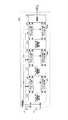
図12は、本発明の実施形態に係る受信装置の第3の実施形態を示す構成図である。本実施の形態による無線通信システムにおいては、送信装置(図示省略)において、送信データビット系列をM本の送信系列にシリアル・パラレル変換し、同一の周波数帯かつ同一の拡散符号群を用いてデータ変調を行い、M本の送信アンテナからNcode本のマルチコードチャネルで同時に送信される場合を示している。FIG. 12 is a configuration diagram illustrating a third embodiment of the receiving device according to the embodiment of the present invention. In the radio communication system according to the present embodiment, a transmission apparatus (not shown) serially / parallel converts a transmission data bit sequence into M transmission sequences, and uses the same frequency band and the same spreading code group as data. A case where modulation is performed and Ncode multicode channels are simultaneously transmitted from M transmission antennas is shown.
本実施形態に係る受信装置600では、ステージ数分の各コードチャネル(本例では、コードチャネル1、2)に対応するマルチパス受信信号再生部611〜614と、各コードチャネルに対応する復調部621、622を用意し、マルチパス干渉キャンセル部615〜618を介して接続される。
本実施形態では、初段の各コードチャネルに対応するマルチパス受信信号再生部611、612への入力信号は、N本の受信アンテナ(ここでは、N=2の例を示している)で受信された受信信号rn(t)であり、マルチパス受信信号再生部611、612は、それぞれ当該コードチャネルの各送信アンテナからの受信パス毎の再生受信信号系列In receiving apparatus 600 according to the present embodiment, multipath received
In the present embodiment, input signals to the multipath received
N個のマルチパス干渉キャンセル部(本例では、N=2)615、616には、受信信号rn(t)と全コードチャネル再生受信信号系列N multipath interference cancellation units (N = 2 in this example) 615 and 616 include a received signal rn (t) and an all-code channel reproduced received signal sequence.
このようにして生成されたマルチパス干渉キャンセル後の受信信号 Received signal after multipath interference cancellation generated in this way
次に、本発明について具体的に計算機シミュレーションを行った例を、図13を用いて説明する。同図は、従来のMLDと2次元MMSEおよび本発明による受信装置の復調方法を用いた場合の受信アンテナ当たりの平均受信Eb/No(情報1ビット当りの信号エネルギーに対する雑音電力密度)に対するスループット特性を計算機シミュレーションにより評価した場合の結果を示す図である。 Next, an example in which a computer simulation is specifically performed for the present invention will be described with reference to FIG. The figure shows the throughput characteristics with respect to the average received Eb / No (noise power density with respect to signal energy per bit of information) per receiving antenna when the conventional MLD, two-dimensional MMSE and the receiving apparatus demodulation method according to the present invention are used. It is a figure which shows the result at the time of evaluating by computer simulation.
本シミュレーションでは、受信装置のマルチパス受信信号再生部を、2ステージで構成し、第1ステージでは、図2の構成を、第2ステージでは図4の構成を用いるものとした。また、マルチパスとして平均受信電力が等しい2パスモデルを仮定した。拡散率は16であり、15コードチャネルを符号多重している(実効的な拡散率は15/16である)。図中Rはターボ符号化を用いたチャネル符号化の符号化率を表し、実線は、本発明法による特性(QR−MLD with 2−stage MPIC)を、点線は従来におけるMMSEの特性を、×印は従来におけるMLDの特性を示している。また、●、○はQPSK変調を用いたMIMO多重(4送信アンテナ、4受信アンテナ)の受信アンテナ当たりの平均受信Eb/Noを、■、□は16QAM変調を用いたMIMO多重の受信アンテナ当たりの平均受信Eb/No特性をそれぞれ表している。 In this simulation, the multipath received signal reproducing unit of the receiving device is configured in two stages, the configuration in FIG. 2 is used in the first stage, and the configuration in FIG. 4 is used in the second stage. In addition, a two-path model with equal average received power is assumed as a multipath. The spreading factor is 16, and 15 code channels are code-multiplexed (the effective spreading factor is 15/16). In the figure, R represents the coding rate of channel coding using turbo coding, the solid line represents the characteristic according to the present invention (QR-MLD with 2-stage MPIC), the dotted line represents the characteristic of the conventional MMSE, x The mark indicates the characteristics of the conventional MLD. Also, ● and ○ are average received Eb / No per receiving antenna of MIMO multiplexing (4 transmitting antennas, 4 receiving antennas) using QPSK modulation, and ■ and □ are per receiving antenna of MIMO multiplexing using 16 QAM modulation. The average received Eb / No characteristic is shown.
同図により、本発明の受信装置の構成を用いることで、従来の信号分離法を用いる場合に比較して、大幅にあるスループットを得るために必要な平均受信電力Eb/Noを低減できていることがわかるが、これは、本発明の受信装置の構成を用いることでより大幅に少ない送信電力で従来と同じスループットを実現できることを示している。換言すれば、同じ送信電力であれば従来よりも大幅にスループットを増大できることを示している。 As shown in the figure, by using the configuration of the receiving apparatus of the present invention, it is possible to reduce the average received power Eb / No necessary to obtain a significant throughput as compared with the case of using the conventional signal separation method. As can be seen, this indicates that the same throughput can be achieved with much less transmission power by using the configuration of the receiving apparatus of the present invention. In other words, it is shown that the throughput can be significantly increased as compared with the conventional case with the same transmission power.
以上説明してきたように、本発明によれば、CDMA方式において情報ビットレートを増大するために複数の送信アンテナから異なるデータを同時送信するMIMO多重を適用したときに、マルチパス干渉を低減し、異なる送信アンテナから送信された信号の高精度な分離を実現することができる。その結果、マルチパスフェージング環境における、受信ビット誤り率・受信パケット誤り率の低減、並びにスループット(誤り無く伝送できる情報ビットの伝送レート)を大幅に向上させることができる。 As described above, according to the present invention, when applying MIMO multiplexing in which different data is simultaneously transmitted from a plurality of transmission antennas in order to increase the information bit rate in the CDMA scheme, multipath interference is reduced, A highly accurate separation of signals transmitted from different transmission antennas can be realized. As a result, in a multipath fading environment, the reception bit error rate and the reception packet error rate can be reduced, and the throughput (the transmission rate of information bits that can be transmitted without error) can be greatly improved.
上記各実施形態では、マルチパス受信信号再生部に、MMSEやMLDなどのアルゴリズム(例えば、アルゴリズムを記述したプログラム)が採用される場合を例示したが、より好ましくは、実用性の範囲の演算量で高精度な信号分離を実現可能とするQR−MLDアルゴリズムを採用するとよい。 In each of the above embodiments, the case where an algorithm such as MMSE or MLD (for example, a program describing the algorithm) is employed for the multipath received signal reproducing unit is illustrated. It is preferable to employ a QR-MLD algorithm that enables highly accurate signal separation.
また、上記各実施形態では、無線通信システムで用いられる受信装置を適用したが、当該受信装置を、移動通信システムで用いている基地局において適用することも勿論可能である。また、無線回線や有線回線を介して上記アルゴリズムを選択的にダウンロードし、無線設備の特性を変化させる、いわゆるソフトウェア無線基地局を本発明に適用することも可能である。 In each of the above embodiments, a receiving apparatus used in a wireless communication system is applied. However, it is of course possible to apply the receiving apparatus in a base station used in a mobile communication system. It is also possible to apply to the present invention a so-called software radio base station that selectively downloads the algorithm through a radio line or a wired line and changes the characteristics of the radio equipment.
本発明は、複数アンテナを用いて信号の復調を行う無線通信システムに適用可能である。 The present invention is applicable to a wireless communication system that performs demodulation of a signal using a plurality of antennas.
Claims (15)
Translated fromJapanese各受信アンテナで受信した受信信号を1次復調して各送信アンテナからの送信信号を推定し、該推定結果に基づいてマルチパス環境における受信アンテナ毎の各パスの受信信号を再生するマルチパス受信信号再生手段と、
前記各受信アンテナで受信した受信信号から、着目するパス以外のパスに対応する前記マルチパス受信信号再生手段により再生された再生受信信号を減じるマルチパス干渉キャンセル手段と、
該マルチパス干渉キャンセル手段により、前記再生受信信号が減じられた受信信号を用いて2次復調を行う復調手段と
を備えることを特徴とする受信装置。A receiving apparatus for receiving transmission signals transmitted bya CDMA system fromaplurality of transmitting antennas by aplurality of receiving antennas,
Multipath reception in which a reception signal received by each reception antenna is primarily demodulated to estimate a transmission signal from each transmission antenna,and a reception signal of each path for each reception antenna in a multipath environment is reproduced based on the estimation result Signal reproduction means;
From said received signal received by each receivingantenna, and multipath interference canceling means for subtracting a regenerative receiversignal reproduced by the multipath reception signal reproducing means corresponding to a path other than the focused path,
Demodulating means for performing secondary demodulation using thereceived signal obtainedby reducing thereproduced received signalby the multipath interference canceling means;
Receiving device, characterized in that it comprisesa.
前記マルチパス受信信号再生手段は、最小平均自乗誤差法(MMSE: Minimum Mean Square Error)を用いて、各受信アンテナで受信した受信信号を1次復調することを特徴とする受信装置。The receiving device according to claim 1,
The multipath reception signal reproducingmeans, minimum mean square error method: the receiving device, characterized in that using a (MMSE Minimum Mean SquareError), forprimary demodulating a received signal received by each receiving antenna.
前記マルチパス受信信号再生手段は、最尤検出法(MLD: Maximum Likelihood Detention)を用いて、各受信アンテナで受信した受信信号を1次復調することを特徴とする受信装置。The receiving device according to claim 1,
The multipath reception signal reproducingmeans, maximum likelihood detection method: using (MLD Maximum LikelihoodDetention), receiving apparatus, characterized byprimary demodulating a received signal received by each receiving antenna.
前記マルチパス受信信号再生手段は、QR分解を利用した最尤検出法を用いて複数パスを一括して前記1次復調を実行することを特徴とする受信装置。The receiving device according to claim 1,
The multipath received signal reproducing means performs the primary demodulation on a plurality of paths at once using a maximum likelihood detection method using QR decomposition.
前記マルチパス受信信号再生手段は、QR分解を利用した最尤検出法を用いてパス毎に前記1次復調を実行することを特徴とする受信装置。The receiving device according to claim 1,
The multipath received signal reproducing means performs the primary demodulation for each path using a maximum likelihood detection method using QR decomposition.
前記マルチパス受信信号再生手段は、各受信アンテナで受信した受信信号を1次復調することにより推定された送信シンボル系列の確からしさに基づいて、受信信号の振幅を制御することを特徴とする受信装置。The receiving device according to claim 2,
The multipath received signal regeneration means controls the amplitude of the received signal based on the probability of the transmission symbol sequenceestimated by performingprimary demodulation on the received signal received by each receiving antenna. apparatus.
前記マルチパス受信信号再生手段は、前記複数の送信アンテナから送信される既知のパイロット信号を用いてチャネル係数を推定することを特徴とする受信装置。The receiving device according to claim 2,
The multipath received signal regeneration means estimates a channel coefficient using known pilot signals transmitted from theplurality of transmitting antennas.
所定数の前記マルチパス受信信号再生手段及び前記マルチパス干渉キャンセル手段を多段接続することを特徴とする受信装置。The receiving device according to claim 2,
A receiving apparatus, wherein a predetermined number of the multipath received signal regeneration means and the multipath interference cancellation means are connected in multiple stages.
前記マルチパス受信信号再生手段が多段接続される場合に、2段目以降の各段において、前段のマルチパス干渉キャンセル手段により前記再生受信信号が減じられた受信信号を用いて、前記複数の送信アンテナから送信される既知のパイロット信号に基づいて推定されるチャネル係数推定値の更新を行うことを特徴とする受信装置。The receiving device according to claim 8, wherein
When said multipath reception signal reproducing means is connected in multiple stages, in each stageof the second and subsequent stages, using thereceived signalof the reconstruction received signal bythe previous stage of the multipath interference canceling meansis reduced,the transmissionof theplurality An apparatus for updating a channel coefficient estimation value estimated based on a known pilot signal transmitted from an antenna.
前記復調手段は、最尤検出法を用いて2次復調を行うことを特徴とする受信装置。The receiving device according to claim 1,
The receiving apparatus, wherein the demodulating means performs secondary demodulation using a maximum likelihood detection method.
前記復調手段は、QR分解を利用した最尤検出法を用いて複数パスを一括して2次復調を行うことを特徴とする受信装置。The receiving device according to claim 1,
The receiving apparatus according to claim 1, wherein the demodulating unit performs secondary demodulation on a plurality of paths at once using a maximum likelihood detection method using QR decomposition.
前記復調手段は、QR分解を利用した最尤検出法を用いてパス毎に2次復調を行うことを特徴とする受信装置。The receiving device according to claim 1,
The receiving apparatus according to claim 1, wherein the demodulation means performs secondary demodulation for each path using a maximum likelihood detection method using QR decomposition.
前記複数の送信アンテナから符号多重された送信信号が送信されたときに、
前記マルチパス受信信号再生手段は、各受信アンテナで受信した受信信号を1次復調して、拡散符号毎に受信アンテナ毎の各パスの受信信号を再生し、
前記マルチパス干渉キャンセル手段は、前記各受信アンテナで受信した受信信号から、着目するパス以外のパスの全拡散符号に対応する前記マルチパス受信信号再生手段により再生された再生受信信号を減じた信号を生成し、
前記復調手段は、前記マルチパス干渉キャンセル手段により前記再生受信信号が減じられた受信信号を用いて、拡散符号毎に2次復調を行うことを特徴とする受信装置。The receiving device according to claim 1,
When a transmission signal code-multiplexed from theplurality of transmission antennas is transmitted,
The multipath reception signal reproducing means, the reception signal received by each receiving antenna and primary demodulatingreproduces the received signal of each path of each receiving antenna for each spreading code,
The multipath interference canceling means, from said received signal received by the receivingantennas, by subtracting the reproduced receivedsignal reproduced by themultipath reception signal reproducing means corresponding toall thespreading codes of paths other than the focused path Generate a signal,
It said demodulating means, using saidmultipathreceptionsignals the reproduced received signalis reducedby the interference cancelingunit, the receiving apparatus and performs secondary demodulation for each spreading code.
各受信アンテナで受信した受信信号から、所定のアルゴリズムを用いて、各送信アンテナからの送信信号を推定する送信信号推定ステップと、
該送信信号推定ステップにより推定された送信信号と、既知のパイロット信号に基づいて推定されるチャネル推定値とを乗算することにより、マルチパス環境における受信アンテナ毎の各パスの受信信号を再生する受信信号再生ステップと、
前記各受信アンテナで受信した受信信号から、着目するパス以外のパスに対応する前記受信信号再生ステップにより再生された再生受信信号を減算する再生受信信号減算ステップと、
該再生受信信号減算ステップにより前記再生受信信号が減算じられた受信信号を用いて復調を行う復調ステップと
を有することを特徴とする受信方法。A receiving method of a receiving apparatus for receiving transmission signals transmitted bya CDMA system fromaplurality of transmitting antennas by aplurality of receiving antennas,
From the reception signal received by each receiving antenna,a transmission signal estimation step of using a predeterminedalgorithmto estimate the transmitted signal from each transmitting antenna,
By multiplying the transmission signal estimatedby the transmit signal estimation step, a channel estimation value estimated based on known pilot signals,the reception to reproduce the received signal of each path for each receive antenna in a multipath environmentA signal regeneration step ;
From said received signal received by each receivingantenna,and the reproduced received signal subtraction step of subtracting the reproduction receivedsignal reproduced by the reception signal reproducing step corresponding to a path other than the focused path,
Ademodulation step for performingdemodulation using thereception signal obtainedby subtracting thereproduction reception signal in the reproduction reception signal subtractionstep;
Receiving method characterized byhaving a.
を備えることを特徴とする無線通信システム。A transmission apparatus comprising aplurality of transmission antennas and transmitting a CDMA signal from each transmission antenna; and the reception apparatus accordingto claim 1;
Wireless communication system comprising:a.
Applications Claiming Priority (3)
| Application Number | Priority Date | Filing Date | Title |
|---|---|---|---|
| JP2004063197 | 2004-03-05 | ||
| JP2004063197 | 2004-03-05 | ||
| PCT/JP2005/003774WO2005086402A1 (en) | 2004-03-05 | 2005-03-04 | Receiver apparatus, receiving method, and wireless communication system |
Publications (2)
| Publication Number | Publication Date |
|---|---|
| JPWO2005086402A1 JPWO2005086402A1 (en) | 2008-01-24 |
| JP4322918B2true JP4322918B2 (en) | 2009-09-02 |
Family
ID=34918146
Family Applications (1)
| Application Number | Title | Priority Date | Filing Date |
|---|---|---|---|
| JP2006510745AExpired - Fee RelatedJP4322918B2 (en) | 2004-03-05 | 2005-03-04 | Reception device, reception method, and wireless communication system |
Country Status (8)
| Country | Link |
|---|---|
| US (1) | US7991360B2 (en) |
| EP (1) | EP1722499B1 (en) |
| JP (1) | JP4322918B2 (en) |
| CN (1) | CN1930813B (en) |
| AT (1) | ATE498948T1 (en) |
| DE (1) | DE602005026370D1 (en) |
| ES (1) | ES2361418T3 (en) |
| WO (1) | WO2005086402A1 (en) |
Cited By (1)
| Publication number | Priority date | Publication date | Assignee | Title |
|---|---|---|---|---|
| JP2006339773A (en)* | 2005-05-31 | 2006-12-14 | Nec Corp | Mimo receiver, reception method, and radio communication system |
Families Citing this family (18)
| Publication number | Priority date | Publication date | Assignee | Title |
|---|---|---|---|---|
| TWI501576B (en) | 2002-07-19 | 2015-09-21 | Rakuten Inc | Groupwise successive interference cancellation for block transmission with reception diversity |
| JP4478119B2 (en)* | 2005-05-25 | 2010-06-09 | パナソニック株式会社 | Receiver |
| US8107549B2 (en)* | 2005-11-30 | 2012-01-31 | Qualcomm, Incorporated | Multi-stage receiver for wireless communication |
| KR100706618B1 (en)* | 2005-12-09 | 2007-04-12 | 한국전자통신연구원 | Soft Decision Demapping Method Suitable for Higher-order Modulation for Iterative Decoder and Its Error Correction Device |
| JP2007300383A (en)* | 2006-04-28 | 2007-11-15 | Fujitsu Ltd | MIMO-OFDM transmitter |
| HUE047810T2 (en)* | 2006-11-06 | 2020-05-28 | Qualcomm Inc | MIMO detection by extinguishing the interference of the on-time signal component |
| EP2245754B1 (en)* | 2007-12-17 | 2016-03-02 | Unwired Planet International Limited | Multi-antenna receiver interference cancellation method and apparatus |
| JP2009272725A (en)* | 2008-04-30 | 2009-11-19 | Sharp Corp | Communication system, reception device, and communication method |
| JP5177527B2 (en)* | 2008-07-28 | 2013-04-03 | シャープ株式会社 | COMMUNICATION SYSTEM, RECEPTION DEVICE, AND COMMUNICATION METHOD |
| CN102119514B (en)* | 2008-08-20 | 2014-10-15 | 高通股份有限公司 | Method and apparatus for sharing a signal on a single channel |
| US8238488B1 (en)* | 2008-09-02 | 2012-08-07 | Marvell International Ltd. | Multi-stream maximum-likelihood demodulation based on bitwise constellation partitioning |
| JP5241437B2 (en)* | 2008-11-13 | 2013-07-17 | 三星電子株式会社 | Reception device and signal processing method |
| CN102282791B (en)* | 2009-01-21 | 2014-07-16 | 日本电气株式会社 | Demodulation method for mimo systems |
| EP2701332B1 (en)* | 2011-04-22 | 2015-11-18 | Mitsubishi Electric Corporation | Communication device using plurality of communication paths |
| JP5803429B2 (en)* | 2011-08-25 | 2015-11-04 | 富士通株式会社 | Receiver |
| WO2013119619A1 (en) | 2012-02-06 | 2013-08-15 | Maxlinear, Inc. | Method and system for a distributed receiver |
| US9722730B1 (en) | 2015-02-12 | 2017-08-01 | Marvell International Ltd. | Multi-stream demodulation schemes with progressive optimization |
| WO2019134754A1 (en) | 2018-01-08 | 2019-07-11 | Telefonaktiebolaget Lm Ericsson (Publ) | Methods and apparatuses for selecting a session management entity for serving a wireless communication device |
Family Cites Families (13)
| Publication number | Priority date | Publication date | Assignee | Title |
|---|---|---|---|---|
| US5506861A (en)* | 1993-11-22 | 1996-04-09 | Ericsson Ge Mobile Comminications Inc. | System and method for joint demodulation of CDMA signals |
| US5887034A (en)* | 1996-03-29 | 1999-03-23 | Nec Corporation | DS-CDMA multiple user serial interference canceler unit and method of transmitting interference replica signal of the same |
| SG84514A1 (en)* | 1998-08-31 | 2001-11-20 | Oki Techno Ct Singapore Pte | Receiving device and channel estimator for use in a cdma communication system |
| JP3515033B2 (en)* | 2000-01-19 | 2004-04-05 | 松下電器産業株式会社 | Interference signal removal apparatus and interference signal removal method |
| GB0016663D0 (en)* | 2000-07-06 | 2000-08-23 | Nokia Networks Oy | Receiver and method of receiving |
| JP3714910B2 (en)* | 2001-02-20 | 2005-11-09 | 株式会社エヌ・ティ・ティ・ドコモ | Turbo receiving method and receiver thereof |
| US7181167B2 (en)* | 2001-11-21 | 2007-02-20 | Texas Instruments Incorporated | High data rate closed loop MIMO scheme combining transmit diversity and data multiplexing |
| JP3829108B2 (en) | 2002-07-26 | 2006-10-04 | ホシデン株式会社 | Card connector |
| US7075972B2 (en)* | 2002-08-19 | 2006-07-11 | Mitsubishi Electric Research Laboratories, Inc. | Intra-cell interference cancellation in a W-CDMA communications network |
| JP3960888B2 (en) | 2002-09-03 | 2007-08-15 | 株式会社エヌ・ティ・ティ・ドコモ | Signal separation method and receiving apparatus |
| US8320301B2 (en)* | 2002-10-25 | 2012-11-27 | Qualcomm Incorporated | MIMO WLAN system |
| KR100470401B1 (en)* | 2002-12-24 | 2005-02-05 | 한국전자통신연구원 | A wireless communication system and method using grouping Maximum Lilelihood Detection |
| US8036325B2 (en)* | 2006-03-09 | 2011-10-11 | Interdigital Technology Corporation | Wireless communication method and apparatus for performing knowledge-based and blind interference cancellation |
- 2005
- 2005-03-04ESES05720046Tpatent/ES2361418T3/ennot_activeExpired - Lifetime
- 2005-03-04DEDE200560026370patent/DE602005026370D1/ennot_activeExpired - Lifetime
- 2005-03-04CNCN2005800071148Apatent/CN1930813B/ennot_activeExpired - Fee Related
- 2005-03-04WOPCT/JP2005/003774patent/WO2005086402A1/enactiveApplication Filing
- 2005-03-04EPEP20050720046patent/EP1722499B1/ennot_activeExpired - Lifetime
- 2005-03-04USUS10/591,663patent/US7991360B2/ennot_activeExpired - Fee Related
- 2005-03-04JPJP2006510745Apatent/JP4322918B2/ennot_activeExpired - Fee Related
- 2005-03-04ATAT05720046Tpatent/ATE498948T1/ennot_activeIP Right Cessation
Cited By (2)
| Publication number | Priority date | Publication date | Assignee | Title |
|---|---|---|---|---|
| JP2006339773A (en)* | 2005-05-31 | 2006-12-14 | Nec Corp | Mimo receiver, reception method, and radio communication system |
| US8036295B2 (en) | 2005-05-31 | 2011-10-11 | Nec Corporation | Radio communication system that uses a MIMO receiver |
Also Published As
| Publication number | Publication date |
|---|---|
| EP1722499A1 (en) | 2006-11-15 |
| CN1930813B (en) | 2010-05-05 |
| WO2005086402A1 (en) | 2005-09-15 |
| US20070197166A1 (en) | 2007-08-23 |
| EP1722499A4 (en) | 2008-06-04 |
| JPWO2005086402A1 (en) | 2008-01-24 |
| ATE498948T1 (en) | 2011-03-15 |
| CN1930813A (en) | 2007-03-14 |
| US7991360B2 (en) | 2011-08-02 |
| DE602005026370D1 (en) | 2011-03-31 |
| ES2361418T3 (en) | 2011-06-16 |
| EP1722499B1 (en) | 2011-02-16 |
Similar Documents
| Publication | Publication Date | Title |
|---|---|---|
| JP4322918B2 (en) | Reception device, reception method, and wireless communication system | |
| KR100624504B1 (en) | Iterative soft interference cancellation and filtering for spectrally efficient high-speed transmission in mimo systems | |
| US7339980B2 (en) | Successive interference cancellation in a generalized RAKE receiver architecture | |
| US7197282B2 (en) | Mobile station loop-back signal processing | |
| RU2484582C2 (en) | Method and apparatus for successive interference subtraction with covariance root processing | |
| JP4072539B2 (en) | Apparatus and method for receiving a signal in a communication system using a multiple-input multiple-output scheme | |
| US8036295B2 (en) | Radio communication system that uses a MIMO receiver | |
| US7463672B2 (en) | Technique for adaptive multiuser equalization in code division multiple access systems | |
| JP2002232397A (en) | Reception processing method and reception apparatus in mobile communication system | |
| US6901122B2 (en) | Method and apparatus for restoring a soft decision component of a signal | |
| US7218692B2 (en) | Multi-path interference cancellation for transmit diversity | |
| CN1757175B (en) | Equalization of multiple signals received for soft handoff in wireless communication systems | |
| JP2006067070A (en) | MIMO system receiving method and apparatus thereof | |
| EP1372308B1 (en) | Method and apparatus for decision directed channel equalization in spread spectrum receivers | |
| KR20050045836A (en) | Method and apparatus for receiver processing in a cdma communications system | |
| KR100789355B1 (en) | Receiver, Receiving Method, and Wireless Communication System | |
| KR100703263B1 (en) | Apparatus and method for removing interference signal in mobile communication system using multiple antennas | |
| KR100651432B1 (en) | Apparatus and method for removing interference signal in mobile communication system using multiple antennas | |
| JP2016527777A (en) | Improved receiver for wireless communication networks | |
| Dahmane | A mew MMSE based cascade filter MUD tracking mode in time-varying channels | |
| Lu et al. | Joint iterative channel estimation for space-time multiuser detection | |
| Yang et al. | Software-defined decision-feedback multi-user detection in frequency domain for single-carrier and multi-carrier CDMA systems-a sequential quadratic programming approach | |
| Karlsson et al. | Improved single-user detector for WCDMA systems based on Griffiths' algorithm | |
| Alimi et al. | A power efficient rake receiver for interference reduction in the mobile communication systems | |
| Thomas | Multiuser interference suppression in wideband broadcast CDMA networks |
Legal Events
| Date | Code | Title | Description |
|---|---|---|---|
| A131 | Notification of reasons for refusal | Free format text:JAPANESE INTERMEDIATE CODE: A131 Effective date:20090310 | |
| A521 | Request for written amendment filed | Free format text:JAPANESE INTERMEDIATE CODE: A523 Effective date:20090501 | |
| TRDD | Decision of grant or rejection written | ||
| A01 | Written decision to grant a patent or to grant a registration (utility model) | Free format text:JAPANESE INTERMEDIATE CODE: A01 Effective date:20090602 | |
| A01 | Written decision to grant a patent or to grant a registration (utility model) | Free format text:JAPANESE INTERMEDIATE CODE: A01 | |
| A61 | First payment of annual fees (during grant procedure) | Free format text:JAPANESE INTERMEDIATE CODE: A61 Effective date:20090603 | |
| R150 | Certificate of patent or registration of utility model | Free format text:JAPANESE INTERMEDIATE CODE: R150 | |
| FPAY | Renewal fee payment (event date is renewal date of database) | Free format text:PAYMENT UNTIL: 20120612 Year of fee payment:3 | |
| FPAY | Renewal fee payment (event date is renewal date of database) | Free format text:PAYMENT UNTIL: 20120612 Year of fee payment:3 | |
| FPAY | Renewal fee payment (event date is renewal date of database) | Free format text:PAYMENT UNTIL: 20130612 Year of fee payment:4 | |
| R250 | Receipt of annual fees | Free format text:JAPANESE INTERMEDIATE CODE: R250 | |
| R250 | Receipt of annual fees | Free format text:JAPANESE INTERMEDIATE CODE: R250 | |
| LAPS | Cancellation because of no payment of annual fees |