JP4320472B2 - Chuck device - Google Patents
Chuck deviceDownload PDFInfo
- Publication number
- JP4320472B2 JP4320472B2JP2007006998AJP2007006998AJP4320472B2JP 4320472 B2JP4320472 B2JP 4320472B2JP 2007006998 AJP2007006998 AJP 2007006998AJP 2007006998 AJP2007006998 AJP 2007006998AJP 4320472 B2JP4320472 B2JP 4320472B2
- Authority
- JP
- Japan
- Prior art keywords
- coil
- bobbin
- fingers
- chuck device
- finger
- Prior art date
- Legal status (The legal status is an assumption and is not a legal conclusion. Google has not performed a legal analysis and makes no representation as to the accuracy of the status listed.)
- Active
Links
Images


Classifications
- B—PERFORMING OPERATIONS; TRANSPORTING
- B25—HAND TOOLS; PORTABLE POWER-DRIVEN TOOLS; MANIPULATORS
- B25J—MANIPULATORS; CHAMBERS PROVIDED WITH MANIPULATION DEVICES
- B25J15/00—Gripping heads and other end effectors
- B25J15/08—Gripping heads and other end effectors having finger members
- B—PERFORMING OPERATIONS; TRANSPORTING
- B25—HAND TOOLS; PORTABLE POWER-DRIVEN TOOLS; MANIPULATORS
- B25J—MANIPULATORS; CHAMBERS PROVIDED WITH MANIPULATION DEVICES
- B25J19/00—Accessories fitted to manipulators, e.g. for monitoring, for viewing; Safety devices combined with or specially adapted for use in connection with manipulators
- B25J19/02—Sensing devices
- B25J19/027—Electromagnetic sensing devices
- B—PERFORMING OPERATIONS; TRANSPORTING
- B25—HAND TOOLS; PORTABLE POWER-DRIVEN TOOLS; MANIPULATORS
- B25B—TOOLS OR BENCH DEVICES NOT OTHERWISE PROVIDED FOR, FOR FASTENING, CONNECTING, DISENGAGING OR HOLDING
- B25B11/00—Work holders not covered by any preceding group in the subclass, e.g. magnetic work holders, vacuum work holders
- B—PERFORMING OPERATIONS; TRANSPORTING
- B25—HAND TOOLS; PORTABLE POWER-DRIVEN TOOLS; MANIPULATORS
- B25J—MANIPULATORS; CHAMBERS PROVIDED WITH MANIPULATION DEVICES
- B25J15/00—Gripping heads and other end effectors
- B25J15/02—Gripping heads and other end effectors servo-actuated
- B25J15/0253—Gripping heads and other end effectors servo-actuated comprising parallel grippers
- B25J15/0266—Gripping heads and other end effectors servo-actuated comprising parallel grippers actuated by articulated links
- Y—GENERAL TAGGING OF NEW TECHNOLOGICAL DEVELOPMENTS; GENERAL TAGGING OF CROSS-SECTIONAL TECHNOLOGIES SPANNING OVER SEVERAL SECTIONS OF THE IPC; TECHNICAL SUBJECTS COVERED BY FORMER USPC CROSS-REFERENCE ART COLLECTIONS [XRACs] AND DIGESTS
- Y10—TECHNICAL SUBJECTS COVERED BY FORMER USPC
- Y10S—TECHNICAL SUBJECTS COVERED BY FORMER USPC CROSS-REFERENCE ART COLLECTIONS [XRACs] AND DIGESTS
- Y10S294/00—Handling: hand and hoist-line implements
- Y10S294/907—Sensor controlled device
- Y—GENERAL TAGGING OF NEW TECHNOLOGICAL DEVELOPMENTS; GENERAL TAGGING OF CROSS-SECTIONAL TECHNOLOGIES SPANNING OVER SEVERAL SECTIONS OF THE IPC; TECHNICAL SUBJECTS COVERED BY FORMER USPC CROSS-REFERENCE ART COLLECTIONS [XRACs] AND DIGESTS
- Y10—TECHNICAL SUBJECTS COVERED BY FORMER USPC
- Y10T—TECHNICAL SUBJECTS COVERED BY FORMER US CLASSIFICATION
- Y10T279/00—Chucks or sockets
- Y10T279/12—Chucks or sockets with fluid-pressure actuator
- Y10T279/1208—Chucks or sockets with fluid-pressure actuator with measuring, indicating or control means
- Y—GENERAL TAGGING OF NEW TECHNOLOGICAL DEVELOPMENTS; GENERAL TAGGING OF CROSS-SECTIONAL TECHNOLOGIES SPANNING OVER SEVERAL SECTIONS OF THE IPC; TECHNICAL SUBJECTS COVERED BY FORMER USPC CROSS-REFERENCE ART COLLECTIONS [XRACs] AND DIGESTS
- Y10—TECHNICAL SUBJECTS COVERED BY FORMER USPC
- Y10T—TECHNICAL SUBJECTS COVERED BY FORMER US CLASSIFICATION
- Y10T279/00—Chucks or sockets
- Y10T279/12—Chucks or sockets with fluid-pressure actuator
- Y10T279/1274—Radially reciprocating jaws
- Y10T279/1291—Fluid pressure moves jaws via mechanical connection
- Y—GENERAL TAGGING OF NEW TECHNOLOGICAL DEVELOPMENTS; GENERAL TAGGING OF CROSS-SECTIONAL TECHNOLOGIES SPANNING OVER SEVERAL SECTIONS OF THE IPC; TECHNICAL SUBJECTS COVERED BY FORMER USPC CROSS-REFERENCE ART COLLECTIONS [XRACs] AND DIGESTS
- Y10—TECHNICAL SUBJECTS COVERED BY FORMER USPC
- Y10T—TECHNICAL SUBJECTS COVERED BY FORMER US CLASSIFICATION
- Y10T279/00—Chucks or sockets
- Y10T279/21—Chucks or sockets with measuring, indicating or control means
Landscapes
- Engineering & Computer Science (AREA)
- Mechanical Engineering (AREA)
- Robotics (AREA)
- Physics & Mathematics (AREA)
- Electromagnetism (AREA)
- Manipulator (AREA)
- Jigs For Machine Tools (AREA)
- Electromagnets (AREA)
Description
Translated fromJapanese本発明は、把持部の開閉作用下にワークを把持することが可能なチャック装置に関し、一層詳細には、前記把持部の開閉量を検出可能な検出部を有するチャック装置に関する。 The present invention relates to a chuck device capable of gripping a workpiece under the opening / closing action of the gripping portion, and more particularly to a chuck device having a detection portion capable of detecting the opening / closing amount of the gripping portion.
従来から、例えば、工作機械の軸部等の先端に取り付けられ、一組の把持部の開閉動作を圧力流体や電気信号の供給作用下に行うことにより、種々の部品等のワークを把持するチャック装置が知られている。 Conventionally, for example, a chuck that is attached to the tip of a shaft portion or the like of a machine tool and grips a workpiece such as various parts by performing opening and closing operations of a set of gripping portions under the supply of pressure fluid or electrical signals. The device is known.
このようなチャック装置では、一般的に、把持するワークの大きさに応じて把持部の開閉量を制御して該ワークの把持を行っている。そのため、この把持部の開閉量を検出可能な検出部を備えたものが知られている(例えば、特許文献1参照)。この検出部は、一組の把持部が変位自在に設けられたガイドレールの上面に設けられ、該ガイドレールに沿って配置された複数のコイルからなる。また、ガイドレールを挟んだ反対側の上面にも同様に別のコイルが複数設けられている。そして、ガイドレールを挟んで対向配置された2つのコイルの間を把持部が変位することにより、出力される誘導出力信号に基づいて前記把持部の開閉量を検出している。 In such a chuck apparatus, the workpiece is generally gripped by controlling the opening / closing amount of the gripping portion in accordance with the size of the workpiece to be gripped. Therefore, what is provided with the detection part which can detect the opening-and-closing amount of this holding part is known (for example, refer to patent documents 1). This detection part is provided on the upper surface of a guide rail in which a pair of gripping parts are provided so as to be displaceable, and is composed of a plurality of coils arranged along the guide rail. Similarly, a plurality of other coils are provided on the upper surface on the opposite side across the guide rail. Then, when the gripping portion is displaced between two coils opposed to each other with the guide rail interposed therebetween, the opening / closing amount of the gripping portion is detected based on the output guidance output signal.
ところで、特許文献1に係る従来技術においては、把持部の変位方向に沿って配置された複数のコイルから検出部を構成しているため、チャック装置における部品点数及び製造コストの増大を招くと共に、前記コイルを複数配置することにより装置の大型化を招くという問題がある。 By the way, in the prior art which concerns on patent documents 1, since the detection part comprises a plurality of coils arranged along the displacement direction of the gripping part, it causes an increase in the number of parts and manufacturing cost in the chuck device, There is a problem in that the arrangement of a plurality of the coils increases the size of the apparatus.
本発明は、前記の課題を考慮してなされたものであり、検出部を設けることによる大型化を抑制しつつ、簡素な構成で把持部の開閉量を高精度に検出することが可能なチャック装置を提供することを目的とする。 The present invention has been made in consideration of the above-described problems, and is capable of accurately detecting the opening / closing amount of the gripping part with a simple configuration while suppressing an increase in size due to the provision of the detection part. An object is to provide an apparatus.
前記の目的を達成するために、本発明は、ボディと、
前記ボディの内部に配設される駆動源と、
前記駆動源により開閉動作するレバー部材と、
前記レバー部材が係合して該レバー部材の開閉動作によって開閉される一組のフィンガと、からなり、
前記フィンガは爪部と本体部とからなり、前記本体部の内部にボビンを収容するボビン孔を有し、
前記ボビンは大径部と小径部とを備えるとともに、前記小径部にコイルが巻回され、
前記駆動源の作用下に前記レバー部材が開閉動作することにより前記フィンガを構成する前記本体部が前記コイルの外周部位を変位して生ずるインピーダンスの変化により前記フィンガの変位量を検出することを特徴とする。To achieve the above object, the present invention comprises abody,
A drive source disposed inside the body;
A lever member that opens and closes by the drive source;
A pair of fingers that are engaged and opened and closed by opening and closing the lever member;
The finger comprises a claw portion and a main body portion, and has a bobbin hole for accommodating a bobbin inside the main body portion,
The bobbin includes a large diameter portion and a small diameter portion, and a coil is wound around the small diameter portion,
A displacement amount of the finger is detected bya change in impedance caused by the body portion constituting the finger displacing an outer peripheral portion of the coil when the lever member is opened and closed under the action of the driving source. And
本発明によれば、軸線方向に沿って延在するボビンと、該ボビンに対して巻回されたコイルとを有し、前記ボビンを前記フィンガの内部に配設している。そして、一組のフィンガが互いに離間した開状態から動作させて閉状態とすることにより、前記フィンガの変位によって前記ボビンに巻回されたコイルのインピーダンス変化が生じ、このインピーダンス変化に基づいてフィンガの開閉量を連続的に検出することができる。According to the present inventionincludes a bobbin extending in theaxial direction, anda coil wound to said bobbin, and disposed thebobbin inside thefinger. Then, by a closed by operating from the open state in which one set offingers are spaced apart from each other, the impedance change of thecoil wound around thebobbin by the displacement of thefinger occurs, thefinger on the basis of the impedance change The opening / closing amount can be continuously detected.
従って、ボビンとコイルとで簡素な検出部構成とし、且つ、ボビンをフィンガの内部に設けることによりチャック装置の大型化を抑制することができると共に、前記ボビンとコイルによってフィンガの開閉量を直接的に検出することができるため、その検出誤差を抑制して高精度に検出を行うことができる。Therefore, the bobbin and the coil havea simpledetection unit configuration, and thebobbin is provided inside thefinger , so that the size of the chuck device can be suppressed,and the opening and closing amount of thefinger can be directly controlled by thebobbin and the coil . Therefore, the detection error can be suppressed and detection can be performed with high accuracy.
また、コイルを、一組のフィンガが互いに離間した開状態において、前記フィンガの間に配設されて外部に露呈させることにより、前記フィンガがワークを把持するため互いに接近するように閉動作する際、前記コイルが徐々に前記フィンガの本体部の内部に収容され、それに伴って生じる前記コイルのインピーダンス変化からフィンガの開閉量を検出することが可能となる。Further, when the coil is closed so that thefingers come close to each other in order to grip the workpiece, the coil is disposed between thefingers and exposed to the outside in a state where the pair offingers are separated from each other. The coil is gradually housed inthe main body of thefinger , and the opening / closing amount of thefinger can be detected from the change in impedance of the coil that accompanies it.
さらに、コイルを一組設け、一組のフィンガが互いに離間した開状態において、前記フィンガの内部にそれぞれ収容させることにより、前記フィンガがワークを把持するため互いに接近するように閉動作する際、前記コイルが徐々に外部へと露呈され、それに伴って生じる前記コイルのインピーダンス変化からフィンガの開閉量を検出することが可能となる。Further, when a pair of coils are provided and thefingers are accommodated in thefingers in an open state in which thefingers are separated from each other, thefingers are closed so as to approach each other in order to grip the workpiece. The coil is gradually exposed to the outside, and the opening / closing amount of thefinger can be detected from the change in the impedance of the coil that occurs accordingly.
またさらに、コイルを一組設け、一組のフィンガが互いに離間した開状態において、一方のコイルを前記フィンガの内部に収容させると共に、他方のコイルを前記フィンガの外部に露呈させることにより、前記フィンガがワークを把持するため互いに接近するように閉動作する際、一方のコイルが徐々に外部へと露呈し、他方のコイルが徐々に前記フィンガの内部に収容される。そのため、一組のコイルに生じるインピーダンス変化が互いに逆の特性となり、その偏差を大きく得ることができるため、前記把持部の開閉量をより一層高精度に検出することが可能となる。Furthermore, when one set of coils is provided and one set offingers is spaced apart from each other, one coil is accommodated inside thefinger and the other coil is exposed to the outside of thefinger , thereby providing thefinger. When gripping the workpiece, the coil is gradually exposed to the outside, and the other coil is gradually housed in thefinger . Therefore, impedance changes occurring in a set of coils have opposite characteristics and a large deviation can be obtained, so that the opening / closing amount of the gripper can be detected with higher accuracy.
さらにまた、ボビンに、軸線方向に沿って延在し前記コイルの挿通される溝部と、
前記溝部の端部に設けられ、該ボビンに巻回される前記コイルの位置を規制する孔部と、
を備えることにより、前記溝部を介して前記ボビンに巻回されるコイルの一端部を好適に前記ボビンの端部へと導くことができると共に、前記孔部に挿通させることによって巻き始め位置が好適に規制されるため、前記コイルの一端部及び他端部を前記ボビンにおける一方の端部側へと集約して前記ボビンに保持させることができる。その結果、コイルが接続される回路基板等を集約することができ、検出部を含むチャック装置の小型化を促進することが可能となる。Still further, a groove extending along the axial direction in the bobbin and through which the coil is inserted,
A hole provided at an end of the groove and restricting the position of the coil wound around the bobbin;
With this, it is possible to suitably guide one end portion of the coil wound around the bobbin through the groove portion to the end portion of the bobbin, and the winding start position is preferable by being inserted through the hole portion. Therefore, the one end and the other end of the coil can be gathered to one end of the bobbin and held on the bobbin. As a result, circuit boards and the like to which the coils are connected can be integrated, and the downsizing of the chuck device including the detection unit can be promoted.
また、ボディに、圧力流体の供給作用下に軸線方向に沿って変位するピストンを設け、前記ピストンの変位に伴ってフィンガを開閉動作させるようにするとよい。すなわち、圧力流体によって駆動するチャック装置において、ピストンの変位量を検出して把持部の開閉量を算出する場合と比較して、前記把持部の開閉量を検出部によって直接的に検出しているため、より高精度な検出を行うことが可能となる。The body may be provided with a piston that is displaced along the axial direction under the pressure fluid supply action, and thefingers are opened and closed in accordance with the displacement of the piston. That is, in the chuck device driven by the pressure fluid, the opening / closing amount of the gripping part is directly detected by the detection unit as compared with the case where the displacement amount of the piston is detected to calculate the opening / closing amount of the gripping part. Therefore, it becomes possible to perform detection with higher accuracy.
本発明によれば、以下の効果が得られる。 According to the present invention, the following effects can be obtained.
すなわち、フィンガの開閉量を検出するために、軸線方向に沿って延在するボビンと、該ボビンに対して巻回されたコイルとを備え、前記ボビンを前記フィンガの本体部の内部に配設することにより、簡素な構成とし、且つ、チャック装置の大型化を抑制することができると共に、前記ボビンとコイルによってフィンガの開閉量を直接的に検出することができるため、その検出誤差を抑制して高精度に検出を行うことができる。That is,in order to detect the opening / closing amount of thefinger , a bobbin extending along the axial direction and a coil wound around thebobbin areprovided , and thebobbin is disposed insidethe main body of thefinger.by, andeasy disjoint structure, and, it is possible to suppress an increase in the size of the chuck device, it is possible to directly detect the opening and closing amount ofthe finger by thebobbin and coil, suppress the detection error Thus, detection can be performed with high accuracy.
本発明に係るチャック装置について好適な実施の形態を挙げ、添付の図面を参照しながら以下詳細に説明する。 Preferred embodiments of the chuck device according to the present invention will be described below and described in detail with reference to the accompanying drawings.
図1において、参照符号10は、本発明の第1の実施の形態に係るチャック装置を示す。 In FIG. 1,
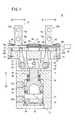
このチャック装置10は、図1〜図3に示されるように、筒状に形成されたチャックボディ12と、前記チャックボディ12の内部に変位自在に設けられるピストン14と、前記ピストン14のロッド部16に係合されたレバー18を介して開閉動作する一組の第1及び第2フィンガ20a、20bを有する把持部22と、前記チャックボディ12の端部に設けられ、前記把持部22の開閉量を検出する検出機構(検出部)24とを含む。 As shown in FIGS. 1 to 3, the
チャックボディ12は、断面略矩形状に形成され、その内部には軸線方向に沿って貫通した貫通孔26が形成されると共に、その側面には、前記貫通孔26の内部に圧力流体を供給する第1及び第2ポート28a、28bが開口している。 The
この貫通孔26には、開口した一端部側にキャップ30が嵌合され、該キャップ30によって前記貫通孔26が閉塞される。また、キャップ30の外周面には、環状のシール部材32が装着され、前記貫通孔26の内周面に当接することにより該貫通孔26内の気密が保持されると共に、該貫通孔26の内周面に装着された係止リング34によって前記キャップ30が前記貫通孔26に対して保持される。 The through
第1及び第2ポート28a、28bは、チャックボディ12の軸線方向(矢印X1、X2方向)に所定間隔離間して設けられ、前記第1ポート28aがピストン14の一端面側(矢印X1方向)に連通し、前記第2ポート28bが前記ピストン14の他端面とキャップ30との間に連通している。なお、第1及び第2ポート28a、28bは、図示しない圧力流体供給源に接続されている。 The first and
また、チャックボディ12の他端部には、プレート状のベース体36が連結され、前記ベース体36には、把持部22を構成する一組の第1及び第2フィンガ20a、20bが変位自在に案内されるレール溝38が形成される。このレール溝38は、ベース体36においてチャックボディ12とは反対側の側面に一直線状に形成され、且つ、前記チャックボディ12の軸線と略直交する長手方向に沿って延在している。そして、ベース体36の両端部には、一組のエンドブロック40a、40bがボルト42によって固定されている。 A plate-
さらに、ベース体36の上部には、該ベース体36及び把持部22の一部を覆うようにカバー44が装着される。このカバー44は、例えば、ベース体36を覆うように折曲されたプレート材から形成され、前記カバー44の端部が前記ベース体36に対してボルト46(図3参照)で固定される。このカバー44は、把持部22の第1及び第2フィンガ20a、20bが挿通されるフィンガ孔48を有し、前記フィンガ孔48は、前記第1及び第2フィンガ20a、20bの変位範囲に応じた大きさで開口している。そのため、第1及び第2フィンガ20a、20bが開閉動作した場合にカバー44と接触することがない。 Further, a
ピストン14の一端面には、例えば、ゴム等の弾性材料からなるダンパ50が装着され、前記ピストン14が把持部22側(矢印X1方向)に向かって変位して前記貫通孔26の内壁面に当接する際の衝撃が緩衝される。 For example, a
一方、ピストン14は、該ピストン14の外周面が貫通孔26の内周面に沿って摺接するように設けられ、前記外周面の環状溝に装着されたピストンパッキン52が前記内周面に当接している。これにより、ピストン14の一端面側及び他端面側における貫通孔26内の気密が好適に保持される。 On the other hand, the
また、ピストン14の外周面には、ピストンパッキン52に隣接して磁石54が配設され、前記磁石54の磁気を図示しない位置検出センサで検知することにより、前記ピストン14の変位位置が確認される。 A
ピストン14の一端面側には、半径内方向に縮径して把持部22側(矢印X1方向)に向かって延在したロッド部16を有し、前記ピストン14の他端面は、キャップ30と対向するように配置される。このロッド部16は、貫通孔26に対して縮径したロッド孔56に挿通され、該ロッド孔56の内周面に設けられたロッドパッキン58が外周面に当接している。 On one end surface side of the
このロッド部16には、一組のレバー18がピン60を介して回動自在に係合される。このレバー18は、それぞれ断面略L字状に形成され、その折曲した略中央部が、チャックボディ12に設けられた一組のリンクピン62を介してそれぞれ回動自在に軸支されている。また、レバー18の一端部側には、それぞれ半円状に切り欠かれた切欠部64が形成され、ロッド部16の端部に装着されたピン60にそれぞれ係合されている。一方、レバー18は、リンクピン62に支持された部位から他端部側に向かって徐々に細軸状に形成され、把持部22を構成する第1及び第2フィンガ20a、20bの内部にそれぞれ軸支されている。A pair of
すなわち、一組のレバー18は、ロッド部16の軸線方向(矢印X1、X2方向)に沿った変位作用下にリンクピン62を介して他端部側が互いに接近又は離間するように回動変位する。 That is, the pair of
把持部22は、図2に示されるように、ベース体36のレール溝38に沿って変位自在に設けられる一組の第1及び第2フィンガ20a、20bを有し、前記第1及び第2フィンガ20a、20bは、前記レール溝38にガイドされるブロック状の本体部66と、該本体部66から突出してワークを把持する爪部68とを有する。 As shown in FIG. 2, the
この本体部66には、その両側部に軸線方向に沿って溝部70(図3参照)がそれぞれ形成され、該溝部70に複数のボール(図示せず)が一直線状に装着される。そして、ベース体36の両端面に装着されたカバープレート72によって前記ボールが溝部70内に保持されると共に、前記ボールが前記溝部70と対向したレール溝38の内壁面に当接して保持される。これにより、把持部22を構成する第1及び第2フィンガ20a、20bが、レール溝38に沿って変位する際の変位抵抗が軽減され、前記レール溝38に沿って円滑に変位することができる。 Grooves 70 (see FIG. 3) are formed on both sides of the
また、本体部66の内部には、爪部68に対して略直交方向に延在し、第1及び第2フィンガ20a、20bの変位方向と略平行に貫通した第1ボビン孔74a、74bがそれぞれ形成される。そして、第1及び第2フィンガ20a、20bがレール溝38に装着された状態で、それぞれの第1ボビン孔74a、74bが一直線状となるように配設される(図1参照)。 Further,
さらに、エンドブロック40a、40bには、第1ボビン孔74a、74bに臨む位置に第2ボビン孔76a、76bが形成され、前記第2ボビン孔76a、76bにはボビン78の大径部80a、80bが挿入される。そして、第1ボビン孔74a、74bと第2ボビン孔76a、76bとが同軸上に設けられているため、該第2ボビン孔76a、76bによってボビン78の両端部が保持される。 Further, the
エンドブロック40a、40bには、上方に向かって開口して第2ボビン孔76a、76bと連通したねじ孔82が形成され、前記ねじ孔82には固定ボルト84が螺合される。このねじ孔82は、第2ボビン孔76a、76bと略直交するように貫通しているため、この固定ボルト84を螺回させることにより前記第2ボビン孔76a、76bに対して接近・離間する方向に変位する。 The end blocks 40a, 40b are formed with screw holes 82 that open upward and communicate with the
すなわち、固定ボルト84を前記ボビン78側(図1中、矢印X2方向)に向かって変位させることにより、第2ボビン孔76a、76bに挿通されたボビン78の外周面が前記固定ボルト84の端部によって押圧されるため、前記ボビン78が前記第2ボビン孔76a、76bの内部に固定される。 That is, by displacing the fixing
これにより、ボビン78の軸線方向(矢印A1、A2方向)への変位が規制され、把持部22の第1ボビン孔74a、74bに挿通された状態で保持される。換言すれば、エンドブロック40a、40bに設けられた固定ボルト84は、ボビン78の軸線方向への変位を規制するストッパとして機能している。 Thereby, the displacement of the
検出機構24は、図2及び図4に示されるように、把持部22を構成する第1及び第2フィンガ20a、20bの内部に挿通されるボビン78と、前記ボビン78の外周面に巻回されるコイル86と、前記コイル86が接続される基板88(図1参照)とからなる。 As shown in FIGS. 2 and 4, the
ボビン78は、長尺な軸体からなり、第1及び第2フィンガ20a、20bにおける第1及び第2ボビン孔76a、76bに挿通される大径部80a、80bと、その軸線方向に沿った略中央部に設けられ、該大径部80a、80bに対して半径内方向に縮径してコイル86が巻回される小径部90とを有する。すなわち、ボビン78は、その両端部に大径部80a、80bが設けられ、該大径部80a、80bに挟まれるように小径部90が設けられる。この大径部80a、80bの直径は、第1及び第2ボビン孔74a、74b、76a、76bの内周径と略同等に設定され、前記第2ボビン孔76a、76bに挿通されて固定ボルト84で支持されることによって前記ボビン78が支持される。 The
また、小径部90は、第1フィンガ20aと第2フィンガ20bとが最も離間した開状態(図2参照)において、該第1フィンガ20aと第2フィンガ20bとの間となるように配置され、第1ボビン孔74a、74bに対して外部に露呈している。小径部90の両端部は、把持部22の開状態において、それぞれ第1ボビン孔74a、74bの内部に若干だけかかるように配置されている。すなわち、小径部90に巻回されたコイル86の両端部も同様に第1ボビン孔74a、74bの内部に若干だけ挿入された状態となる。 The small-
コイル86は、小径部90に対して螺旋状に巻回され、その外周径は、大径部80a、80bと略同等若しくは若干だけ小さく設定される。 The
さらに、第2フィンガ20bに挿通される大径部80a、80b及び小径部90には、その外周面に軸線方向に沿ったコイル溝(溝部)92が一直線状に形成され、前記コイル溝92に沿ってコイル86が装着される。また、大径部80a側となる小径部90の端部には、半径方向に貫通したコイル孔(孔部)94(図4参照)が形成され、前記コイル孔94がコイル溝92と接続されている。詳細には、第2フィンガ20b側となる大径部80b及び小径部90のコイル溝92に沿ってコイル86が挿通された後、コイル孔94に挿通されたコイル86が第1フィンガ20aに挿通された大径部80a側から前記第2フィンガ20b側へと戻るように小径部90の外周面に対してコイル86が巻回される。 Further, the large-
これにより、コイル溝92は、コイル86の一端部を、その巻き始めとなる大径部80a側まで送り込むために設けられ、前記コイル溝92に挿通されたコイル86の一部は、小径部90に巻回された残余のコイル86によって覆われるため、前記コイル溝92から外部へと脱落することがなく、前記コイル溝92内に保持されると共に、コイル孔94に挿通されることによってコイル86の巻き始め位置が規制される。As a result, the
基板88には、コイル86の両端部がそれぞれ接続され、前記コイル86によるインピーダンスの変化が出力され、このインピーダンス変化に基づいて把持部22の開閉量を算出する。 Both ends of the
本発明の第1の実施の形態に係るチャック装置10は、基本的には以上のように構成されるものであり、次にその動作並びに作用効果について説明する。なお、図1に示されるように、ピストン14が把持部22側(矢印X1方向)に上昇し、一組の第1及び第2フィンガ20a、20bが開状態であるワークの非把持状態を初期状態とする。 The
先ず、図示しない圧力流体供給源から第1ポート28aに対して圧力流体を供給することにより、ピストン14が把持部22から離間する方向(矢印X2方向)へと変位し、該ピストン14のロッド部16に係合された一組のレバー18の一端部がそれぞれ下方へと引張される。なお、この場合、第2ポート28bは大気開放状態としておく。これにより、一組のレバー18がそれぞれリンクピン62を支点として他端部が互いに接近する方向へと回動し、前記他端部が係合された一組の第1及び第2フィンガ20a、20bがベース体36のレール溝38に沿って互いに接近する方向(矢印A1方向)へと略水平に変位する。これにより、把持部22を構成する第1及び第2フィンガ20a、20bによってワークが所定の圧力で挟持されて把持される。 First, by supplying a pressure fluid from a pressure fluid supply source (not shown) to the
この場合、第1及び第2フィンガ20a、20bが互いに接近する方向へと変位することにより、第1ボビン孔74a、74bの内部にコイル86が両端部側からそれぞれ挿通され、前記コイル86の外周側が覆われることとなる。そして、把持部22とコイル86との相対位置の変化に伴って前記コイル86のインピーダンスが変化し、このインピーダンス変化に基づいた前記コイル86の電圧変化を検出することによって基板88において第1及び第2フィンガ20a、20bの変位量が算出される。なお、この場合、第1及び第2フィンガ20a、20bの変位量は、コイル86に対してそれぞれ略同等となる。 In this case, the first and
一方、フィンガによるワークの把持状態を解除する場合には、図示しない切換弁の切換作用下に第1ポート28aに供給されていた圧力流体を第2ポート28bに対して供給する。この場合、第1ポート28aは大気開放状態としておく。これにより、第2ポート28bから貫通孔26に導入された圧力流体の押圧作用下にピストン14が把持部22側(矢印X1方向)に向かって変位し、それに伴って、ロッド部16に係合された一組のレバー18がそれぞれリンクピン62を支点として他端部が互いに離間する方向へと回動する。そのため、レバー18の係合された一組の第1及び第2フィンガ20a、20bが、ベース体36のレール溝38に沿って互いに離間する方向(矢印A2方向)へと略水平に変位し、ワークを把持した前記第1及び第2フィンガ20a、20bが互いに離間する方向へと変位することにより、前記ワークの把持状態が解除される。On the other hand, when releasing the gripping state of the workpiece by thefinger, the pressure fluid supplied to the
この場合にも、第1及び第2フィンガ20a、20bが互いに離間する方向へと変位することにより、第1ボビン孔74a、74bに収容されたコイル86の一部がそれぞれ外部へと変位し、前記コイル86の外周側が第1及び第2フィンガ20a、20bの外部に徐々に露呈していくこととなる。そして、把持部22とコイル86との相対位置の変化に伴って前記コイル86のインピーダンスが変化し、このインピーダンス変化に基づいた前記コイル86の電圧変化を検出することによって第1及び第2フィンガ20a、20bの変位量が算出される。 Also in this case, when the first and
以上のように、第1の実施の形態では、把持部22の開閉量を検出可能な検出機構24を、第1及び第2フィンガ20a、20bの内部に挿通されたボビン78と、該ボビン78の中央部に巻回された単一のコイル86とから構成し、前記コイル86をボビン78の小径部90に対して螺旋状に巻回している。そして、第1ボビン孔74aを通じて第1及び第2フィンガ20a、20bをコイル86の外周側に沿って変位させることにより、前記コイル86のインピーダンス変化に基づいて前記第1及び第2フィンガ20a、20bの変位量を連続的に検出することができる。その結果、検出機構24によって把持部22の開閉量を直接的に検出しているため検出誤差の小さな高精度な検出を行うことができ、該把持部22でワークを正確に把持することができると共に、コイル86及びボビン78から検出機構24を簡素な構成とすることができる。 As described above, in the first embodiment, the
また、検出機構24を構成するコイル86及びボビン78は、それぞれ把持部22の内部に収容可能に構成されているため、前記検出機構24を設けることによるチャック装置10の大型化を抑制することができる。すなわち、チャック装置10を大型化させることなく検出機構24を設けることが可能となる。 Further, since the
さらに、検出機構24は、ワークを把持する把持部22の開閉量を高精度に検出することができるため、前記ワークの大きさに応じて前記把持部22の開閉量を高精度に制御することができる。例えば、把持部22を開閉動作させるピストン14の変位量を検出し、該変位量に基づいて把持部22の開閉量を検出する場合と比較し、前記把持部22の開閉量を直接的に検出しているため、前記開閉量の誤差が小さくより高精度な検出を行うことができる。 Further, since the
さらにまた、コイル86をボビン78のコイル溝92に挿通させ、該コイル86の両端部を集約することが可能であるため、前記両端部が接続される基板88を前記コイル86の片側のみに設ければよく、前記基板88を集約してチャック装置10の小型化を促進させることができる。 Furthermore, since the
次に、第2の実施の形態に係るチャック装置100を図5に示す。なお、以下に示す第2〜第5の実施の形態に係るチャック装置100、120、140、150と、第1の実施の形態に係るチャック装置10と同一の構成要素には同一の参照符号を付して、その詳細な説明を省略する。 Next, a
この第2の実施の形態に係るチャック装置100では、検出機構102を構成するボビン104の両端部側に一組のコイル106a、106bが配設され、把持部22が開状態となった状態で前記コイル106a、106bがそれぞれ第1ボビン孔74a、74bの内部に収納可能に配設される点で、第1の実施の形態に係るチャック装置10と相違している。 In the
このチャック装置100では、検出機構102を構成するボビン104の略中央に大径部108が形成され、該大径部108を中心とした両端部にコイル106a、106bが巻回される一組の小径部110a、110bが形成される。この小径部110a、110bの長さは、第1ボビン孔74a、74bの長さより若干だけ長く形成され、把持部22を構成する第1及び第2フィンガ20a、20bが互いに離間した開状態において、前記小径部110a、110bの一部が外部に露呈する。すなわち、小径部110a、110bに巻回されるコイル106a、106bの一部が外部に露呈することとなる。 In this
また、第1フィンガ20aに挿通される小径部110aの外周面には、軸線方向に沿って第1コイル溝(溝部)112が形成され、該第1コイル溝112には前記小径部110aに巻回されるコイル106aが挿通される。この第1コイル溝112は、一方の小径部110aから大径部108を介して第2フィンガ20bに挿通される小径部110bの外周面まで延在している。また、第2フィンガ20bに挿通される小径部110bには、コイル106aが挿通される第1コイル溝112に加え、コイル106bが挿通される第2コイル溝(溝部)114が設けられる。そして、第1及び第2コイル溝112、114に挿通されたコイル106a、106bがそれぞれエンドブロック40bを通じて外部に導かれる。 In addition, a first coil groove (groove portion) 112 is formed along the axial direction on the outer peripheral surface of the
このように、第2の実施の形態では、第1及び第2フィンガ20a、20bに対応するように一組のコイル106a、106bをそれぞれ設け、前記第1及び第2フィンガ20a、20bを変位させることにより、第1ボビン孔74a、74bに収容されたコイル106a、106bのインピーダンスの変化に基づいて前記第1及び第2フィンガ20a、20bの変位量を連続的に検出することができる。As described above, in the second embodiment, a pair of
次に、第3の実施の形態に係るチャック装置120を図6に示す。 Next, a
この第3の実施の形態に係るチャック装置120では、第1及び第2フィンガ20a、20bが互いに離間した開状態において、該第1フィンガ20aの第1ボビン孔74aに検出機構122を構成する第1コイル124を配設すると共に、該第1及び第2フィンガ20a、20bの間となるボビン128の略中央部に別の第2コイル126を配設している点で、第1及び第2の実施の形態に係るチャック装置10、100と相違している。 In the
このチャック装置120では、検出機構122を構成するボビン128の一端部及び略中央部にそれぞれ小径部130a、130bが形成され、第2フィンガ20bに収容されるボビン128の他端部に大径部132が形成される。そして、小径部130a、130bにはそれぞれ第1及び第2コイル124、126が巻回され、一方の第1コイル124が第1フィンガ20aの第1ボビン孔74aに収容される。また、他方の第2コイル126は、第1フィンガ20aと第2フィンガ20bとの間に配置されて外部に露呈すると共に、把持部22の閉状態では前記第2フィンガ20bの第1ボビン孔74bに収容される。 In the
このように、第3の実施の形態では、第1及び第2フィンガ20a、20bが開閉動作した際に、一方の第1コイル124が徐々に外部に露呈し、反対に、他方の第2コイル126が徐々に覆われていく。すなわち、2つの第1及び第2コイル124、126によるインピーダンス変化がそれぞれ逆の特性となるため、その偏差を大きく得ることが可能となり、前記インピーダンス変化に基づいた前記第1及び第2フィンガ20a、20bの変位量の検出精度をさらに向上させることができる。 As described above, in the third embodiment, when the first and
次に、第4の実施の形態に係るチャック装置140を図7及び図8に示す。 Next, a
この第4の実施の形態に係るチャック装置140では、第1及び第2フィンガ20a、20bの第1ボビン孔74a、74bにそれぞれ筒体142a、142bが挿入され、該筒体142a、142bの内部に検出機構144を構成するボビン146を挿通させると共に、前記ボビン146の両端部にそれぞれ一組のコイル148a、148bを設けている点で、第1〜第3の実施の形態に係るチャック装置10、100、120と相違している。 In the
このチャック装置140では、例えば、アルミニウム、真鍮等の金属製材料からなる筒体142a、142bが第1及び第2フィンガ20a、20bの内部に配設され、前記筒体142a、142bの内部に挿通されたボビン146の小径部110a、110bに対してそれぞれ一組のコイル148a、148bが巻回されている。すなわち、把持部22の開状態において、一組のコイル148a、148bがそれぞれ第1及び第2フィンガ20a、20bの第1ボビン孔74a、74bに収容されている。 In the
このように、第4の実施の形態では、コイル148a、148bの外周側にそれぞれ筒体142a、142bを設けることにより、前記筒体142a、142bの材質によって前記コイル148a、148bによる出力特性を変化させることができる。すなわち、筒体142a、142bの材質を任意に選択することにより、所望の出力特性を得ることが可能となる。 As described above, in the fourth embodiment, by providing the
次に、第5の実施の形態に係るチャック装置150を図9〜図11に示す。 Next, a
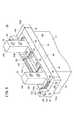
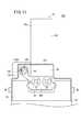
この第5の実施の形態に係るチャック装置150では、検出機構152を把持部22の外部に略平行に設けている点で、第1〜第4の実施の形態に係るチャック装置10、100、120、140と相違している。 In the
このチャック装置150では、ベース体36の上部に把持部22と略平行に一組のガイド体154a、154bを設け、前記ガイド体154a、154bの内部にボビン156の大径部158a、158bが挿通される。このガイド体154a、154bは、円筒状に形成され、第1及び第2フィンガ20a、20bの端部に装着されたカバープレート160に保持される。詳細には、カバープレート160には、ガイド体154a、154b側に向かって膨出した膨出部162を備え、前記第1及び第2フィンガ20a、20bの両端部に装着されたカバープレート160の膨出部162の間にガイド体154a、154bが保持される。この際、膨出部162の内部にはボビン156が挿通される。 In the
また、ボビン156は、その両端部に形成された大径部158a、158bがエンドブロック163a、163b側に配置されたガイド体154a、154bに収容されて前記エンドブロック163a、163bに形成された第2ボビン孔76a、76bに保持される。また、ボビン156の略中央部に形成された小径部164にコイル166が巻回される。このコイル166は、一組のガイド体154a、154bの間に配置され、外部に露呈している。 Further, the
さらに、ベース体36の上部には、ガイド体154a、154b及び把持部22の一部を覆うようにカバー168が装着される。 Furthermore, a
そして、第1及び第2フィンガ20a、20bを閉動作させることにより、該第1及び第2フィンガ20a、20bと共に一組のガイド体154a、154bがコイル166を覆うように互いに接近する方向(矢印A1方向)へと変位し、前記ガイド体154a、154bによって覆われるコイル166のインピーダンスの変化に基づいて前記第1及び第2フィンガ20a、20bの変位量が連続的に検出される。Then, by closing the first and
このように、第5の実施の形態では、第1及び第2フィンガ20a、20bに対して検出機構152を略平行として外部に設けているため、前記第1及び第2フィンガ20a、20bに第1ボビン孔74a、74bを設ける必要がなく、従来のチャック装置の第1及び第2フィンガ20a、20bを流用することができる。そのため、チャック装置150に対して検出機構152を簡便且つ安価で設けることが可能となり、製造コストの低減を図ることができる。 As described above, in the fifth embodiment, since the
本発明の第1〜第5の実施の形態に係るチャック装置は、上述の実施の形態に限らず、本発明の要旨を逸脱することなく、種々の構成を採り得ることはもちろんである。 The chuck devices according to the first to fifth embodiments of the present invention are not limited to the above-described embodiments, and it is needless to say that various configurations can be adopted without departing from the gist of the present invention.
また、上述した第1〜第5の実施の形態に係るチャック装置10、100、120、140、150は、圧力流体の供給作用下に把持部22を開閉動作させるエア駆動式について説明したが、これに限定されるものではなく、例えば、モータ等の回転駆動源の回転駆動力によって開閉動作する電動式のチャック装置に上述した検出機構を設けるようにしてもよい。 In addition, the
この場合には、回転駆動力を把持部22へと伝達する伝達機構のガタツキなどの影響を受けることなく、前記把持部22の開閉量を高精度に検出することが可能となる。 In this case, it is possible to detect the opening / closing amount of the gripping
10、100、120、140、150…チャック装置
12…チャックボディ 14…ピストン
20a…第1フィンガ 20b…第2フィンガ
22…把持部
24、102、122、144、152…検出機構
26…貫通孔 28a…第1ポート
28b…第2ポート 36…ベース体
40a、40b…エンドブロック 72、160…カバープレート
74a、74b…第1ボビン孔 76a、76b…第2ボビン孔
78、104、128、146、156…ボビン
80a、80b、108、132、158a、158b…大径部
86、106a、106b、148a、148b、166…コイル
90、110a、110b、130a、130b、164…小径部
92…コイル溝 112…第1コイル溝
114…第2コイル溝 124…第1コイル
126…第2コイル 142a、142b…筒体
154a、154b…ガイド体 162…膨出部DESCRIPTION OF
Claims (6)
Translated fromJapanese前記ボディの内部に配設される駆動源と、A drive source disposed inside the body;
前記駆動源により開閉動作するレバー部材と、A lever member that opens and closes by the drive source;
前記レバー部材が係合して該レバー部材の開閉動作によって開閉される一組のフィンガと、からなり、A pair of fingers that are engaged and opened and closed by opening and closing the lever member;
前記フィンガは爪部と本体部とからなり、前記本体部の内部にボビンを収容するボビン孔を有し、The finger comprises a claw portion and a main body portion, and has a bobbin hole for accommodating a bobbin inside the main body portion,
前記ボビンは大径部と小径部とを備えるとともに、前記小径部にコイルが巻回され、The bobbin includes a large diameter portion and a small diameter portion, and a coil is wound around the small diameter portion,
前記駆動源の作用下に前記レバー部材が開閉動作することにより前記フィンガを構成する前記本体部が前記コイルの外周部位を変位して生ずるインピーダンスの変化により前記フィンガの変位量を検出することを特徴とするチャック装置。A displacement amount of the finger is detected by a change in impedance caused by the body portion constituting the finger displacing an outer peripheral portion of the coil when the lever member is opened and closed under the action of the driving source. Chuck device.
前記コイルは、一組のフィンガが互いに離間した開状態において、前記フィンガの間に配設されて外部に露呈する長さを有することを特徴とするチャック装置。The chuck device according to claim 1,
The chuck device according to claim 1, wherein the coil has alength that is disposed between thefingers and exposed to the outside in an open state in which a pair offingers are separated from each other.
前記コイルは一組設けられ、一組のフィンガが互いに離間した開状態において、前記フィンガの内部にそれぞれ収容される長さを有することを特徴とするチャック装置。The chuck device according to claim 1,
One set of the coils is provided, and the chuck devicehas alength accommodated in each of thefingers in an open state in which the pair offingers are separated from each other.
前記コイルは一組設けられ、一組のフィンガが互いに離間した開状態において、一方のコイルが前記フィンガの内部に収容されると共に、他方のコイルが前記フィンガの外部に露呈する長さであることを特徴とするチャック装置。The chuck device according to claim 1,
The coil is provided one set in the open state in which a pair offingers spaced from one another, that with one coil is housed inside thefinger,the length of the other coils exposed to the outside of thefingers A chuck device characterized by the above.
前記ボビンには、軸線方向に沿って延在し前記コイルの挿通される溝部と、
前記溝部の端部に設けられ、該ボビンに巻回される前記コイルの位置を規制する孔部と、
を備えることを特徴とするチャック装置。In the chuck device according to any one of claims 1 to 4,
The bobbin has a groove extending along the axial direction and through which the coil is inserted;
A hole provided at an end of the groove and restricting the position of the coil wound around the bobbin;
A chuck device comprising:
前記駆動源は、圧力流体の供給作用下に軸線方向に沿って変位するピストンを備え、前記ピストンの変位に伴って前記フィンガを開閉動作させることを特徴とするチャック装置。In the chuck device according to any one of claims 1 to 5,
The chuck device according to claim 1, wherein thedriving source includes a pistonthat is displaced along an axial direction under a pressure fluid supply action, and opens and closes thefinger in accordance with the displacement of the piston.
Priority Applications (6)
| Application Number | Priority Date | Filing Date | Title |
|---|---|---|---|
| JP2007006998AJP4320472B2 (en) | 2007-01-16 | 2007-01-16 | Chuck device |
| TW096150207ATWI337574B (en) | 2007-01-16 | 2007-12-26 | Chuck apparatus |
| DE102008004407.5ADE102008004407B4 (en) | 2007-01-16 | 2008-01-14 | jig |
| KR1020080003979AKR100921235B1 (en) | 2007-01-16 | 2008-01-14 | Chuck device |
| US12/014,759US8100414B2 (en) | 2007-01-16 | 2008-01-15 | Chuck apparatus |
| CN2008100020796ACN101224505B (en) | 2007-01-16 | 2008-01-16 | Chuck device |
Applications Claiming Priority (1)
| Application Number | Priority Date | Filing Date | Title |
|---|---|---|---|
| JP2007006998AJP4320472B2 (en) | 2007-01-16 | 2007-01-16 | Chuck device |
Publications (3)
| Publication Number | Publication Date |
|---|---|
| JP2008173692A JP2008173692A (en) | 2008-07-31 |
| JP2008173692A5 JP2008173692A5 (en) | 2008-11-06 |
| JP4320472B2true JP4320472B2 (en) | 2009-08-26 |
Family
ID=39510105
Family Applications (1)
| Application Number | Title | Priority Date | Filing Date |
|---|---|---|---|
| JP2007006998AActiveJP4320472B2 (en) | 2007-01-16 | 2007-01-16 | Chuck device |
Country Status (6)
| Country | Link |
|---|---|
| US (1) | US8100414B2 (en) |
| JP (1) | JP4320472B2 (en) |
| KR (1) | KR100921235B1 (en) |
| CN (1) | CN101224505B (en) |
| DE (1) | DE102008004407B4 (en) |
| TW (1) | TWI337574B (en) |
Families Citing this family (17)
| Publication number | Priority date | Publication date | Assignee | Title |
|---|---|---|---|---|
| US4965825A (en) | 1981-11-03 | 1990-10-23 | The Personalized Mass Media Corporation | Signal processing apparatus and methods |
| USRE47642E1 (en) | 1981-11-03 | 2019-10-08 | Personalized Media Communications LLC | Signal processing apparatus and methods |
| CN101954638B (en)* | 2010-10-18 | 2012-01-04 | 湖南大学 | Automatic line-grasping control method of deicing robot in high-voltage transmission line |
| CN102357894A (en)* | 2011-09-22 | 2012-02-22 | 严义科 | Three-jaw manipulator measuring bearing diameter |
| CN102357896A (en)* | 2011-10-17 | 2012-02-22 | 严义科 | Three-jaw manipulator for measuring diameter of bearing |
| CN102491087B (en)* | 2011-12-23 | 2014-01-15 | 东莞市新泽谷机械制造股份有限公司 | Electronic component pinching mechanism |
| CN102785105A (en)* | 2012-07-23 | 2012-11-21 | 太仓市旭达机械设备有限公司 | Motor-driven workbench |
| CN103112009B (en)* | 2012-12-27 | 2016-01-20 | 宁波大正工业机器人技术有限公司 | A kind of autoloader finger cylinder special detection device and detection method |
| DE102015004404B4 (en)* | 2015-04-11 | 2016-11-24 | Günther Zimmer | Precision gripper |
| JP6628076B2 (en)* | 2015-06-30 | 2020-01-08 | Smc株式会社 | Chuck device |
| CN106239391A (en)* | 2016-08-22 | 2016-12-21 | 浙江伟联科技股份有限公司 | A kind of pneumatic reciprocating clamping device |
| CN106799611B (en)* | 2017-03-26 | 2018-11-20 | 唐山滦创科技服务有限公司 | A kind of pneumatic type clamping device |
| CN109590707B (en)* | 2018-10-12 | 2020-07-10 | 杭州亦侬农业科技有限公司 | Plugging device for mesh optical fiber jumper wire interface |
| JP7021062B2 (en)* | 2018-12-07 | 2022-02-16 | Ckd株式会社 | Gripping device |
| CN109673930A (en)* | 2018-12-30 | 2019-04-26 | 广州富港万嘉智能科技有限公司 | Cake producing device and cake production method |
| JP7448739B2 (en)* | 2019-05-27 | 2024-03-13 | Smc株式会社 | Chuck device drive system and its control method |
| TWI751813B (en)* | 2020-11-30 | 2022-01-01 | 寅翊智造股份有限公司 | Feeding apparatus of automatic processing machine |
Family Cites Families (9)
| Publication number | Priority date | Publication date | Assignee | Title |
|---|---|---|---|---|
| US4509783A (en)* | 1982-12-29 | 1985-04-09 | Ionescu Alexandru D | Smart hand |
| US4682805A (en)* | 1986-02-18 | 1987-07-28 | The Perkin-Elmer Corporation | Grasping finger position sensor for a robot system |
| JPH11114869A (en)* | 1997-10-20 | 1999-04-27 | Amitec:Kk | Chuck opening detector in slide opening/closing type chuck device |
| DE19747015B4 (en)* | 1997-10-24 | 2006-09-21 | Asg Luftfahrttechnik Und Sensorik Gmbh | Gripping device, in particular for automatic printing and / or inserting machines |
| JP2000180109A (en)* | 1998-12-14 | 2000-06-30 | Ribekkusu:Kk | Position detector |
| JP2000343473A (en)* | 1999-06-03 | 2000-12-12 | Smc Corp | Parallel opening/closing chuck |
| JP3293802B2 (en)* | 1999-07-07 | 2002-06-17 | エスエムシー株式会社 | Chuck with position detection function |
| KR100516496B1 (en)* | 2001-12-03 | 2005-09-23 | 주식회사 포스코 | An apparatus for automatically adjusting block gap of fresh trimmer |
| JP2006218580A (en)* | 2005-02-10 | 2006-08-24 | Smc Corp | Work gripping chuck and control method thereof |
- 2007
- 2007-01-16JPJP2007006998Apatent/JP4320472B2/enactiveActive
- 2007-12-26TWTW096150207Apatent/TWI337574B/enactive
- 2008
- 2008-01-14KRKR1020080003979Apatent/KR100921235B1/enactiveActive
- 2008-01-14DEDE102008004407.5Apatent/DE102008004407B4/enactiveActive
- 2008-01-15USUS12/014,759patent/US8100414B2/enactiveActive
- 2008-01-16CNCN2008100020796Apatent/CN101224505B/enactiveActive
Also Published As
| Publication number | Publication date |
|---|---|
| JP2008173692A (en) | 2008-07-31 |
| US8100414B2 (en) | 2012-01-24 |
| TW200911484A (en) | 2009-03-16 |
| KR100921235B1 (en) | 2009-10-12 |
| CN101224505B (en) | 2010-06-09 |
| TWI337574B (en) | 2011-02-21 |
| KR20080067575A (en) | 2008-07-21 |
| DE102008004407B4 (en) | 2016-03-31 |
| DE102008004407A1 (en) | 2008-07-17 |
| CN101224505A (en) | 2008-07-23 |
| US20080169619A1 (en) | 2008-07-17 |
Similar Documents
| Publication | Publication Date | Title |
|---|---|---|
| JP4320472B2 (en) | Chuck device | |
| JP4304631B2 (en) | Chuck device | |
| CN107112127B (en) | Wire holding device and wire holding method | |
| US8919842B2 (en) | Robot arm with tendon connector plate and linear actuator | |
| CN111997951B (en) | Driving system of chuck device and control method thereof | |
| JP7034210B2 (en) | Gripping equipment and analytical equipment for handling sample containers | |
| JP6499063B2 (en) | Workpiece gripping device | |
| US20200263710A1 (en) | Bent sensor for position transducer | |
| JP2011255451A (en) | Guide member for inserting wire and method for inserting wire | |
| KR101506286B1 (en) | Solenoid valve and manufacturing method | |
| JP2007292484A (en) | Linear sensor with guide | |
| Colombo | Modelization and optimization of a vacuum gripping-releasing device for micromanipulation | |
| CN110815264B (en) | Gripping device | |
| JP3320677B2 (en) | Opening and closing chuck | |
| CN117999151A (en) | Pneumatic clamp holder | |
| JP4721065B2 (en) | Load detection mechanism | |
| JPS62213928A (en) | Chuck device for assembly machine | |
| JP2014061573A (en) | Collet chuck device and machine tool including the same | |
| TW202337658A (en) | Gripper base and gripper system | |
| IT202200001058U1 (en) | SCREWING DEVICE | |
| JP2006334746A (en) | Gripping device | |
| CN112571441A (en) | Automatic mechanical gripper with variable diameter | |
| JP2021164977A (en) | Clamping device and work holding method | |
| CN105793619A (en) | Measuring device for moving range of side gear | |
| JPH10284893A (en) | Linear work inserter |
Legal Events
| Date | Code | Title | Description |
|---|---|---|---|
| A521 | Request for written amendment filed | Free format text:JAPANESE INTERMEDIATE CODE: A523 Effective date:20080918 | |
| A621 | Written request for application examination | Free format text:JAPANESE INTERMEDIATE CODE: A621 Effective date:20080918 | |
| A977 | Report on retrieval | Free format text:JAPANESE INTERMEDIATE CODE: A971007 Effective date:20081217 | |
| A131 | Notification of reasons for refusal | Free format text:JAPANESE INTERMEDIATE CODE: A131 Effective date:20081224 | |
| A521 | Request for written amendment filed | Free format text:JAPANESE INTERMEDIATE CODE: A523 Effective date:20090223 | |
| TRDD | Decision of grant or rejection written | ||
| A01 | Written decision to grant a patent or to grant a registration (utility model) | Free format text:JAPANESE INTERMEDIATE CODE: A01 Effective date:20090421 | |
| A01 | Written decision to grant a patent or to grant a registration (utility model) | Free format text:JAPANESE INTERMEDIATE CODE: A01 | |
| A61 | First payment of annual fees (during grant procedure) | Free format text:JAPANESE INTERMEDIATE CODE: A61 Effective date:20090519 | |
| R150 | Certificate of patent or registration of utility model | Ref document number:4320472 Country of ref document:JP Free format text:JAPANESE INTERMEDIATE CODE: R150 Free format text:JAPANESE INTERMEDIATE CODE: R150 | |
| FPAY | Renewal fee payment (event date is renewal date of database) | Free format text:PAYMENT UNTIL: 20120612 Year of fee payment:3 | |
| FPAY | Renewal fee payment (event date is renewal date of database) | Free format text:PAYMENT UNTIL: 20130612 Year of fee payment:4 | |
| R250 | Receipt of annual fees | Free format text:JAPANESE INTERMEDIATE CODE: R250 | |
| R250 | Receipt of annual fees | Free format text:JAPANESE INTERMEDIATE CODE: R250 | |
| R250 | Receipt of annual fees | Free format text:JAPANESE INTERMEDIATE CODE: R250 | |
| R250 | Receipt of annual fees | Free format text:JAPANESE INTERMEDIATE CODE: R250 | |
| R250 | Receipt of annual fees | Free format text:JAPANESE INTERMEDIATE CODE: R250 | |
| R250 | Receipt of annual fees | Free format text:JAPANESE INTERMEDIATE CODE: R250 | |
| R250 | Receipt of annual fees | Free format text:JAPANESE INTERMEDIATE CODE: R250 | |
| R250 | Receipt of annual fees | Free format text:JAPANESE INTERMEDIATE CODE: R250 | |
| R250 | Receipt of annual fees | Free format text:JAPANESE INTERMEDIATE CODE: R250 | |
| R250 | Receipt of annual fees | Free format text:JAPANESE INTERMEDIATE CODE: R250 | |
| R250 | Receipt of annual fees | Free format text:JAPANESE INTERMEDIATE CODE: R250 | |
| R255 | Notification that request for automated payment was rejected | Free format text:JAPANESE INTERMEDIATE CODE: R2525 | |
| R250 | Receipt of annual fees | Free format text:JAPANESE INTERMEDIATE CODE: R250 | |
| R250 | Receipt of annual fees | Free format text:JAPANESE INTERMEDIATE CODE: R250 | |
| R250 | Receipt of annual fees | Free format text:JAPANESE INTERMEDIATE CODE: R250 |