JP4320346B2 - Actuator, camera blade driving device, and actuator manufacturing method - Google Patents
Actuator, camera blade driving device, and actuator manufacturing methodDownload PDFInfo
- Publication number
- JP4320346B2 JP4320346B2JP2007086447AJP2007086447AJP4320346B2JP 4320346 B2JP4320346 B2JP 4320346B2JP 2007086447 AJP2007086447 AJP 2007086447AJP 2007086447 AJP2007086447 AJP 2007086447AJP 4320346 B2JP4320346 B2JP 4320346B2
- Authority
- JP
- Japan
- Prior art keywords
- rotor
- output member
- actuator
- blade
- welding
- Prior art date
- Legal status (The legal status is an assumption and is not a legal conclusion. Google has not performed a legal analysis and makes no representation as to the accuracy of the status listed.)
- Expired - Fee Related
Links
- 238000004519manufacturing processMethods0.000titleclaimsdescription7
- 238000003466weldingMethods0.000claimsdescription21
- 239000000758substrateSubstances0.000claimsdescription15
- 230000013011matingEffects0.000claims2
- 230000005284excitationEffects0.000claims1
- 229920005989resinPolymers0.000description13
- 239000011347resinSubstances0.000description13
- 239000000463materialSubstances0.000description6
- 238000005304joiningMethods0.000description5
- 238000010586diagramMethods0.000description4
- 238000000034methodMethods0.000description4
- 239000004734Polyphenylene sulfideSubstances0.000description3
- 238000006073displacement reactionMethods0.000description3
- 230000004048modificationEffects0.000description3
- 238000012986modificationMethods0.000description3
- 239000004033plasticSubstances0.000description3
- 229920000069polyphenylene sulfidePolymers0.000description3
- 230000006866deteriorationEffects0.000description2
- 230000001678irradiating effectEffects0.000description2
- 230000007774longtermEffects0.000description2
- 230000005415magnetizationEffects0.000description2
- 238000000465mouldingMethods0.000description2
- 230000003287optical effectEffects0.000description2
- 229920001707polybutylene terephthalatePolymers0.000description2
- 238000003825pressingMethods0.000description2
- 230000001105regulatory effectEffects0.000description2
- 229920001169thermoplasticPolymers0.000description2
- 239000004416thermosoftening plasticSubstances0.000description2
- 229910000859α-FeInorganic materials0.000description2
- 229930182556PolyacetalNatural products0.000description1
- 238000005452bendingMethods0.000description1
- 239000011230binding agentSubstances0.000description1
- 230000004907fluxEffects0.000description1
- 238000003384imaging methodMethods0.000description1
- 239000004973liquid crystal related substanceSubstances0.000description1
- 239000006247magnetic powderSubstances0.000description1
- 239000000155meltSubstances0.000description1
- 238000002844meltingMethods0.000description1
- 230000008018meltingEffects0.000description1
- 238000002156mixingMethods0.000description1
- 229910001172neodymium magnetInorganic materials0.000description1
- 229920006122polyamide resinPolymers0.000description1
- 229920001225polyester resinPolymers0.000description1
- 239000004645polyester resinSubstances0.000description1
- 229920006324polyoxymethylenePolymers0.000description1
- 239000000843powderSubstances0.000description1
- 229910052761rare earth metalInorganic materials0.000description1
- 150000002910rare earth metalsChemical class0.000description1
- 230000035939shockEffects0.000description1
Images


Classifications
- G—PHYSICS
- G03—PHOTOGRAPHY; CINEMATOGRAPHY; ANALOGOUS TECHNIQUES USING WAVES OTHER THAN OPTICAL WAVES; ELECTROGRAPHY; HOLOGRAPHY
- G03B—APPARATUS OR ARRANGEMENTS FOR TAKING PHOTOGRAPHS OR FOR PROJECTING OR VIEWING THEM; APPARATUS OR ARRANGEMENTS EMPLOYING ANALOGOUS TECHNIQUES USING WAVES OTHER THAN OPTICAL WAVES; ACCESSORIES THEREFOR
- G03B9/00—Exposure-making shutters; Diaphragms
- G03B9/08—Shutters
- G03B9/10—Blade or disc rotating or pivoting about axis normal to its plane
- H—ELECTRICITY
- H02—GENERATION; CONVERSION OR DISTRIBUTION OF ELECTRIC POWER
- H02K—DYNAMO-ELECTRIC MACHINES
- H02K1/00—Details of the magnetic circuit
- H02K1/06—Details of the magnetic circuit characterised by the shape, form or construction
- H02K1/22—Rotating parts of the magnetic circuit
- H02K1/28—Means for mounting or fastening rotating magnetic parts on to, or to, the rotor structures
- H02K1/30—Means for mounting or fastening rotating magnetic parts on to, or to, the rotor structures using intermediate parts, e.g. spiders
- H—ELECTRICITY
- H02—GENERATION; CONVERSION OR DISTRIBUTION OF ELECTRIC POWER
- H02K—DYNAMO-ELECTRIC MACHINES
- H02K37/00—Motors with rotor rotating step by step and without interrupter or commutator driven by the rotor, e.g. stepping motors
- H02K37/10—Motors with rotor rotating step by step and without interrupter or commutator driven by the rotor, e.g. stepping motors of permanent magnet type
- H02K37/12—Motors with rotor rotating step by step and without interrupter or commutator driven by the rotor, e.g. stepping motors of permanent magnet type with stationary armatures and rotating magnets
- H02K37/14—Motors with rotor rotating step by step and without interrupter or commutator driven by the rotor, e.g. stepping motors of permanent magnet type with stationary armatures and rotating magnets with magnets rotating within the armatures
- H02K37/16—Motors with rotor rotating step by step and without interrupter or commutator driven by the rotor, e.g. stepping motors of permanent magnet type with stationary armatures and rotating magnets with magnets rotating within the armatures having horseshoe armature cores
- H—ELECTRICITY
- H02—GENERATION; CONVERSION OR DISTRIBUTION OF ELECTRIC POWER
- H02K—DYNAMO-ELECTRIC MACHINES
- H02K7/00—Arrangements for handling mechanical energy structurally associated with dynamo-electric machines, e.g. structural association with mechanical driving motors or auxiliary dynamo-electric machines
- H02K7/14—Structural association with mechanical loads, e.g. with hand-held machine tools or fans
- H—ELECTRICITY
- H02—GENERATION; CONVERSION OR DISTRIBUTION OF ELECTRIC POWER
- H02K—DYNAMO-ELECTRIC MACHINES
- H02K15/00—Processes or apparatus specially adapted for manufacturing, assembling, maintaining or repairing of dynamo-electric machines
- H02K15/02—Processes or apparatus specially adapted for manufacturing, assembling, maintaining or repairing of dynamo-electric machines of stator or rotor bodies
- H02K15/03—Processes or apparatus specially adapted for manufacturing, assembling, maintaining or repairing of dynamo-electric machines of stator or rotor bodies having permanent magnets
- Y—GENERAL TAGGING OF NEW TECHNOLOGICAL DEVELOPMENTS; GENERAL TAGGING OF CROSS-SECTIONAL TECHNOLOGIES SPANNING OVER SEVERAL SECTIONS OF THE IPC; TECHNICAL SUBJECTS COVERED BY FORMER USPC CROSS-REFERENCE ART COLLECTIONS [XRACs] AND DIGESTS
- Y10—TECHNICAL SUBJECTS COVERED BY FORMER USPC
- Y10T—TECHNICAL SUBJECTS COVERED BY FORMER US CLASSIFICATION
- Y10T29/00—Metal working
- Y10T29/49—Method of mechanical manufacture
- Y10T29/49002—Electrical device making
- Y10T29/49009—Dynamoelectric machine
- Y10T29/49012—Rotor
Landscapes
- Engineering & Computer Science (AREA)
- Power Engineering (AREA)
- Physics & Mathematics (AREA)
- General Physics & Mathematics (AREA)
- Shutters For Cameras (AREA)
- Diaphragms For Cameras (AREA)
- Reciprocating, Oscillating Or Vibrating Motors (AREA)
Description
Translated fromJapanese本発明は、アクチュエータ、カメラ用羽根駆動装置及びアクチュエータの製造方法に関する。 The present invention relates to an actuator, a camera blade driving device, and an actuator manufacturing method.
従来からカメラの羽根の駆動に用いられるアクチュエータとしては、ロータと、ステータと、ステータを励磁するためのコイルと、ロータの回動を羽根に伝達するための出力部材とを備えたものが知られている。特許文献1には、このロータと出力部材とがインサート成形によって形成されているものが開示されている。 2. Description of the Related Art Conventionally, actuators that are used to drive camera blades include a rotor, a stator, a coil for exciting the stator, and an output member for transmitting rotation of the rotor to the blades. ing.
しかしながら、ロータと出力部材とがインサート成形によって形成されている場合には、ロータに対する出力部材の角度位置を精度よく成形することが困難であった。
そこで、溶着によりロータと出力部材とを接合する場合には、溶着前に、ロータに対する出力部材の角度位置の微調整を行うことができる。これにより、ロータに対する出力部材の角度位置の精度を向上させることができる。
しかしながらこのように溶着接合した場合であっても、長期的な使用などにより、ロータと出力部材との接合が弱くなり、ロータと出力部材との位置ずれが生じる恐れがある。特に、シャッタスピードの高速化に伴うロータ及び出力部材への負荷の増大により、このような事態が発生する恐れがある。However, when the rotor and the output member are formed by insert molding, it is difficult to accurately form the angular position of the output member with respect to the rotor.
Therefore, when the rotor and the output member are joined by welding, the angular position of the output member with respect to the rotor can be finely adjusted before welding. Thereby, the precision of the angular position of the output member with respect to the rotor can be improved.
However, even in the case of welding and bonding in this manner, the rotor and the output member may be weakly bonded due to long-term use or the like, and the rotor and the output member may be misaligned. In particular, such a situation may occur due to an increase in loads on the rotor and the output member as the shutter speed increases.
そこで、本発明は、ロータと出力部材との接合が強化されたアクチュエータ、カメラ用羽根駆動装置及びアクチュエータの製造方法を提供することを目的とする。 Accordingly, an object of the present invention is to provide an actuator, a blade driving device for a camera, and a method for manufacturing the actuator, in which the connection between the rotor and the output member is reinforced.
上記目的は、励磁用コイルと、前記コイルへの通電によって異なる極性に励磁されるステータと、周方向に異なる極性に着磁されると共に前記ステータとの間で磁力が作用することにより回動するロータと、前記ロータと一体に回転して該ロータの回動を他の部材に出力する出力部材とを備え、前記出力部材は、前記ロータに嵌合し、前記ロータの嵌合面には、凹凸部が形成されており、前記出力部材は、溶着によって、前記凹凸部に対応するように変形して前記ロータに接合されている、ことを特徴とするアクチュエータによって達成できる。
この構成により、ロータの凹凸部に沿うように出力部材が変形するので、溶着後のロータに対する出力部材の位置ずれを防止でき、ロータと出力部材の接合が強化される。The purpose is to rotate by applying a magnetic force between the exciting coil, a stator that is excited to have different polarity by energizing the coil, and a different polarity in the circumferential direction. A rotor and an output member that rotates integrally with the rotor and outputs the rotation of the rotor to another member; the output member is fitted to the rotor; The actuator is characterized in that an uneven portion is formed, and the output member is deformed so as to correspond to the uneven portion by welding and is joined to the rotor.
With this configuration, the output member is deformed along the uneven portion of the rotor, so that the output member can be prevented from being displaced with respect to the rotor after welding, and the connection between the rotor and the output member is strengthened.
また、上記構成において、前記ロータは、焼結磁石である、構成を採用できる。
この構成により、ロータは焼結磁石であるため、磁性樹脂材料により形成されたロータを採用した場合よりも、トルクを向上させることができる。In the above configuration, the rotor may be a sintered magnet.
With this configuration, since the rotor is a sintered magnet, the torque can be improved as compared with the case where a rotor formed of a magnetic resin material is employed.
また、上記構成において、前記ロータの溶着箇所は、該ロータの磁極の境界である、構成を採用できる。
この構成により、ロータの溶着箇所は磁極の境界であるので、ロータが磁性樹脂材料に成形されたものであっても、溶着によるロータの磁気特性の劣化を抑制できる。In the above configuration, a configuration in which the welding position of the rotor is a boundary between magnetic poles of the rotor can be adopted.
With this configuration, the welded portion of the rotor is the boundary between the magnetic poles, so that deterioration of the magnetic properties of the rotor due to welding can be suppressed even if the rotor is formed of a magnetic resin material.
また、上記目的は、開口を有する基板と、前記開口を開閉する羽根と、前記羽根を駆動するアクチュエータとを備え、前記アクチュエータは、上記に記載されたアクチュエータである、ことを特徴とするカメラ用羽根駆動装置によっても達成できる。
この構成により、ロータと出力部材の位置ずれが防止されるアクチュエータをカメラ用羽根駆動装置に採用することにより、シャッタスピードの高速化に対向できると共に、長期的な使用によっても故障の発生を防止できる。Further, the object is provided with a substrate having an opening, a blade that opens and closes the opening, and an actuator that drives the blade, and the actuator is the actuator described above. This can also be achieved by a blade driving device.
With this configuration, an actuator that prevents the displacement of the rotor and the output member from being used in the camera blade drive device can be used to oppose the increase in shutter speed, and can also prevent occurrence of failure even after long-term use. .
また、上記目的は、周方向に異なる極性に着磁されたロータと、前記ロータに接合され該ロータと一体に回転して該ロータの回動を他の部材に出力する出力部材とを含むアクチュエータの製造方法であって、前記出力部材と嵌合するロータの嵌合面に凹凸部を形成する工程と、前記出力部材を前記嵌合面に嵌合させる工程と、前記出力部材が前記凹凸部に対応するように溶着させる工程とを有する、ことを特徴とするアクチュエータの製造方法によっても達成できる。
この構成により、ロータと出力部材との接合を強化することができる。Another object of the present invention is to provide an actuator including a rotor magnetized with different polarities in the circumferential direction and an output member that is joined to the rotor and rotates integrally with the rotor and outputs the rotation of the rotor to another member. And a step of forming an uneven portion on a fitting surface of a rotor to be fitted to the output member, a step of fitting the output member to the fitting surface, and the output member being the uneven portion. It can also be achieved by an actuator manufacturing method characterized by comprising a step of welding so as to correspond to the above.
With this configuration, the joint between the rotor and the output member can be strengthened.
本発明によれば、ロータと出力部材との接合が強化されたアクチュエータ、カメラ用羽根駆動装置及びアクチュエータの製造方法を提供できる。 ADVANTAGE OF THE INVENTION According to this invention, the manufacturing method of the actuator, the blade drive device for cameras, and the actuator with which joining with the rotor and the output member was strengthened can be provided.
以下、図面を参照して複数の実施例について説明する。 Hereinafter, a plurality of embodiments will be described with reference to the drawings.
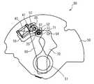
以下、本発明に係る一実施形態について図面を参照して説明する。図1は本実施例に係る電磁アクチュエータの主要部の構成を示した図である。
電磁アクチュエータ1は、ステータ10、ロータ20、コイル40等から構成される。
電磁アクチュエータ1は、U字状に形成されてその両端部に第1磁極部11、第2磁極部12を有するステータ10、周方向に異なる2極に着磁され円筒形状を成すロータ20、コイルボビン41に巻回され通電により互いに異なる極性を第1磁極部11及び第2磁極部12に生じさせるコイル40などを備えている。
また、ロータ20の被写体側には(図4参照)、ロータ20の回動を外部へ出力する出力部材30が取り付けられている。これにより、出力部材30はロータ20と一体的に所定角度範囲を回動する。Hereinafter, an embodiment of the present invention will be described with reference to the drawings. FIG. 1 is a diagram showing the configuration of the main part of the electromagnetic actuator according to the present embodiment.
The
The
An
ロータ20は焼結磁石により形成されている。詳細には、ロータ20は、異方性フェライト焼結磁石である。尚、ロータ20は、希土類焼結磁石や等方性フェライト焼結磁石であってもよい。 The
出力部材30は、レーザ光を透過するポリアセタール樹脂により成形されている。尚、出力部材の材質についても上記以外でもよく、一般的なプラスチック材料である熱可塑性の、ポリエステル−ポリブチレンテレフタレート樹脂や、液晶ポリエステル樹脂、ポリフェニレンサルファイド樹脂、ポリフェニレンスルフィド樹脂などでもよい。しかし、色についてはレーザ光が透過する色である。 The
図2及び図3は、このような電磁アクチュエータを駆動源として採用したカメラ用羽根駆動装置90の透視図である。図2は、全開状態でのカメラ用羽根駆動装置90の透視図であり、図3は、全閉状態でのカメラ用羽根駆動装置90の透視図である。
電磁アクチュエータ1を採用したカメラ用羽根駆動装置90は、基板50、第1羽根60、第2羽根70などから構成される。基板50は、撮影用の開口51を有し、図中において基板50よりも手前側に配置された第1羽根60及び第2羽根70の駆動により開口51を全閉又は全開状態にする。また、電磁アクチュエータ1は、第1羽根60及び第2羽根70が配置された側の基板50の裏側に配置されている。従って、図2及び図3の電磁アクチュエータ1は、図1と左右対称に示されている。2 and 3 are perspective views of a camera
A camera
基板50には、出力部材30の回動を逃がすために逃げ孔52が円弧状に形成されている。出力部材30は逃げ孔52を貫通して所定範囲の回動が許容される。即ち、逃げ孔52は、出力部材30の回動範囲を規制することにより、ロータ20の回動範囲を規制する機能を有している。 A
第1羽根60及び第2羽根70は、それぞれに形成された長孔61及び長孔71に出力部材30が係合して、基板50に形成された軸部53、軸部54を中心に所定の範囲揺動する。これにより、ロータ20の回動が出力部材30を介して第1羽根60及び第2羽根70に伝達され、第1羽根60及び第2羽根70はシャッタ動作を行う。 The
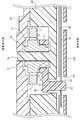
図4は、カメラ用羽根駆動装置90の構成を示した断面図である。
基板50よりも撮像素子側には電磁アクチュエータ1を基板50との間で保持する押え板80が配置され、基板50よりも被写体側には第1羽根60及び第2羽根70を基板50との間で保持する羽根押え板100が配置されている。
基板50には、光軸方向の撮像素子側に向けて延在した支軸55が形成され、ロータ20は支軸55によって回動自在に支持される。FIG. 4 is a cross-sectional view showing the configuration of the camera
A
A
ロータ20は、径の大きさが相違する大径部21及び小径部22を有している。大径部21は、小径部22よりも撮像素子側に形成されており、第1磁極部11及び第2磁極部12と対向する。従って、ロータ20は、大径部21と第1磁極部11及び第2磁極部12との間で作用する磁力を主として回動される。 The
小径部22には、出力部材30の円筒部31が圧入固定される。円筒部31には、小径部22よりも若干径の小さい嵌合孔34が形成されている。ここで、出力部材30の円筒部31とロータ20の小径部22が圧入固定された状態で、出力部材30の円筒部31とロータ20の大径部21のそれぞれの外径の大きさは同じになるように構成されている。従って、小径部22が出力部材30と勘合する嵌合面の機能を有する。 The
出力部材30は、円筒部31から径方向外側に延在したアーム部32と、アーム部32の先端から光軸方向の被写体側に折れ曲がって形成されたピン部33を有する。ピン部33は、長孔61及び長孔71と係合する。尚、羽根押え板100には、ピン部33の揺動を逃がすための逃げ孔101が形成されている。 The
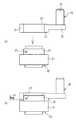
次に、ロータ20と出力部材30との接合方法について詳細に説明する。
図5は、接合方法についての説明図である。
図5に示すように、小径部22には、有底の穴部23が形成されている。
まず、図5(a)に示すように、出力部材30の嵌合孔34に、小径部22を嵌合させる。Next, a method for joining the
FIG. 5 is an explanatory diagram of the joining method.
As shown in FIG. 5, a bottomed
First, as shown in FIG. 5A, the
次に、図5(b)に示すように、ロータ20と出力部材30とを接合すべく、ロータ20及び出力部材30の径方向外側から小径部22の穴部23近傍に向けて、レーザを照射する。照射されたレーザは出力部材30を透過し、穴部23近傍の嵌合孔34の箇所がレーザの熱により溶け出し、嵌合孔34から溶け出した樹脂が穴部23内に流れ込む。一定時間放置すると、嵌合孔34から溶け出した樹脂が固まり、穴部23の形状に対応するように変形する。これにより、溶着後のロータ20に対する出力部材30の位置ずれを防止でき、ロータ20と出力部材30との接合が強化される。 Next, as shown in FIG. 5B, in order to join the
尚、ロータ20は、前述したように焼結磁石であるため、レーザ照射によっても溶け出すことがない。また、焼結磁石によりロータ20は形成されているため、磁性樹脂によりロータを形成した場合と比較し、ロータ20自体を小型化した場合であっても、強いトルクを維持できる。従って、電磁アクチュエータ1自体を小型化することもできる。また、シャッタスピードの高速化にも対応できる。 In addition, since the
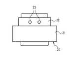
次に、穴部23について詳細に説明する。
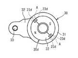
図6は、穴部23の説明図である。
図6に示すように、穴部23は2箇所に併設されている。レーザを照射する際には、この穴部23の間に向けて照射する。出力部材30を小径部22に嵌合させた状態でレーザを照射すると、2箇所に形成された穴部23の間から出力部材30が溶け出し、穴部23内に流れ込む。このように、穴部23を設けることにより、ロータ20の出力部材30に対する軸線方向及び周方向の位置ずれを防止できる。Next, the
FIG. 6 is an explanatory diagram of the
As shown in FIG. 6, the
次に、ロータ20の変形例について説明する。
図7は、変形例に係るロータの説明図である。
図7(a)には、小径部22に横溝部23aが周方向に伸びて形成されているロータ20aが示されている。これにより、溶着後の、ロータ20と出力部材30との軸線方向での位置ずれを防止できる。また、横溝部23aは周方向に延在しているので、横溝部23a付近にレーザが照射されればよく、レーザ照射の位置をラフに設定することができる。これにより作業性が向上する。Next, a modified example of the
FIG. 7 is an explanatory diagram of a rotor according to a modification.
FIG. 7A shows a
図7(b)には、横溝部23bが形成されているロータ20bが示されている。図7(a)に示した、横溝部23aと異なり、横溝部23bが途中で途切れている。これにより、ロータ20と出力部材30との周方向での位置ずれを防止できる。 FIG. 7B shows the
図7(c)は、横溝部23c1、縦溝部23c2が形成されているロータ20cが示されている。横溝部23c1は、周方向に延在している。縦溝部23c2は、ロータ20の軸線方向に延在している。このように、横溝部23c1及び縦溝部23c2により十字状に形成されていることにより、ロータ20cと出力部材30との周方向及び軸線方向での位置ずれを防止できる。尚、レーザ照射する際には、縦溝部23c2近傍に照射する必要がある。 FIG. 7C illustrates the
次に、実施例2に係る電磁アクチュエータについて説明する。尚、上記実施例1と同様の箇所については同一の符号を付することにより説明を省略する。
図8は、実施例2に係る電磁アクチュエータのロータ及び出力部材の正面図である。
ロータ20dは、磁性樹脂材料、即ちプラスチックマグネットにより形成されている。詳細には、SmFeN磁石粉末にポリアミド樹脂を混合して成形されている。尚、ロータの材質は上記以外でもよく、例えば、磁性粉としてNdFeBなどを用い、バインダ樹脂として熱可塑性のポリフェニレンスルフィド樹脂や、ポリエステル−ポリブチレンテレフタレート樹脂などを用いてもよい。Next, an electromagnetic actuator according to Example 2 will be described. In addition, about the location similar to the said Example 1, the description is abbreviate | omitted by attaching | subjecting the same code | symbol.
FIG. 8 is a front view of the rotor and the output member of the electromagnetic actuator according to the second embodiment.
The
ロータ20dは、N極及びS極に着磁され、磁極の境界を挟むように、穴部23dが形成されている。穴部23dは、実施例1に示したロータ20と同様に、小径部22に形成されている。尚、穴部23dは、ロータ20dを成形する際に一体的に成形される。レーザ溶着の際には、磁極の境界である溶着箇所Aに向けて、ロータ20d及び出力部材30の径方向外側から照射する。 The
ロータ20dの磁極の境界位置はロータ20が等方性磁石であれば着磁時に、異方性磁石であれば異方化着磁時に決定され、穴部23dにより挟まれる位置に磁極の境界位置がくるように形成する。また、各着磁時に境界位置にマーキングをする。ロータ20dの磁極の境界位置はその他、表面磁束密度測定器を用いロータ20dの境界位置を検出し、その位置にマーキングをしてもよい。またロータ20dの磁極に対して所望の角度となるように圧入された出力部材30の外形状からロータ20dの磁極の境界位置を判断してもよい。 The boundary position of the magnetic pole of the
レーザ溶着時には、ロータ20dのレーザが照射された部位とその近傍の出力部材30がレーザの熱により溶解され、ロータ20dと出力部材30とが溶着される。よってレーザ溶着時におけるロータ20dのレーザの熱による熱衝撃、溶解することによる形状変形がロータ20dの磁気特性を劣化させる場合があるが、上述したようにロータ20dの磁極の境界にレーザを照射することにより、ロータ20dの磁極部が溶解されることがないので溶着によるロータ20dの磁気特性の劣化を抑制できる。 At the time of laser welding, the portion of the
以上本発明の好ましい実施形態について詳述したが、本発明は係る特定の実施形態に限定されるものではなく、特許請求の範囲に記載された本発明の要旨の範囲内において、変形・変更が可能である。 Although the preferred embodiments of the present invention have been described in detail above, the present invention is not limited to such specific embodiments, and modifications and changes can be made within the scope of the gist of the present invention described in the claims. Is possible.
上記実施例において、ロータ20が周方向に2極に着磁された例をあげたが、周方向に4極など、多極に着磁されていてもよい。 In the above embodiment, the
上記実施例において、焼結磁石のロータ20の場合に溶着箇所が1箇所の例や、プラスチックマグネットのロータ20dの場合に溶着箇所が2箇所の例をあげたが接着箇所は何箇所でもよく、少なくとも1箇所が溶着されていればよい。 In the above-described embodiment, an example of one welding location in the case of the
上記実施例において、ロータ20dには穴部23dが磁極の境界を挟むように形成されている例をあげたが、穴部23dは磁極の境界付近に少なくとも1箇所形成されていればよい。また、磁極の境界を挟むように適宜数形成してもよい。 In the above embodiment, the
上記実施例において、ロータ20に穴部23や横溝部23a、23b、23c1、縦溝部23c2を形成した例をあげたが、形状はこれに限らず、出力部材30の一部が溶け出し、流れ込むことによりロータ20と出力部材30の位置ずれを防止できる凹形状であればよい。 In the above embodiment, the
上記実施例において、第1羽根60及び第2羽根70の2枚の羽根を駆動する例をあげたが、開口51より小さい絞り開口部を有する1枚の絞り羽根や、NDフィルタを有する少なくとも1枚の羽根を駆動してもよい。 In the above-described embodiment, an example in which the two blades of the
1 電磁アクチュエータ
10 ステータ
11 第1磁極部
12 第2磁極部
20 ロータ
21 大径部
22 小径部
23 穴部
23a、23b、23c1 横溝部
23c2 縦溝部
30 出力部材
31 円筒部
32 アーム部
33 ピン部
34 嵌合孔
40 コイル
41 コイルボビン
50 基板
51 開口
52 逃げ孔
60 第1羽根
70 第2羽根
90 カメラ用羽根駆動装置DESCRIPTION OF
Claims (4)
Translated fromJapanese前記出力部材は、前記ロータに嵌合し、
前記ロータの嵌合面には、凹凸部が形成されており、
前記出力部材は、溶着によって、前記凹凸部に対応するように変形して前記ロータに接合されており、
前記ロータの溶着箇所は、該ロータの磁極の境界であり、
前記ロータの嵌合面の凹凸部は、穴部、前記ロータの周方向に伸び途中で途切れた横溝部、及び前記ロータの軸線方向に伸びた縦溝部のいずれかである、ことを特徴とするアクチュエータ。An excitation coil, a stator that is excited to have a different polarity by energizing the coil, a rotor that is magnetized to have a different polarity in the circumferential direction, and that rotates when a magnetic force acts between the stator, An output member that rotates integrally with the rotor and outputs the rotation of the rotor to another member;
The output member is fitted to the rotor,
The mating surface of the rotor has an uneven portion,
The output member is deformed so as to correspond to the concavo-convex portion by welding, and is joined to the rotor,
The welding location of the rotor is the boundary of the magnetic poles of the rotor,
Uneven portion of the fitting surface of said rotor, holes, lateral groove portion broken extending midway in a circumferential direction of the rotor, andis any one of longitudinal grooves extending in the axial direction of the rotor, characterized in that Actuator.
前記アクチュエータは、請求項1又は2に記載されたアクチュエータである、ことを特徴とするカメラ用羽根駆動装置。A substrate having an opening, a blade that opens and closes the opening, and an actuator that drives the blade,
3. The camera blade driving device according to claim 1, wherein the actuator is the actuator according to claim 1.
前記出力部材と嵌合するロータの嵌合面に凹凸部を形成する工程と、
前記出力部材を前記嵌合面に嵌合させる工程と、
前記出力部材が前記凹凸部に対応するように溶着させる工程とを有し、
前記ロータの溶着箇所は、該ロータの磁極の境界であり、
前記ロータの嵌合面の凹凸部は、穴部、前記ロータの周方向に伸び途中で途切れた横溝部、及び前記ロータの軸線方向に伸びた縦溝部のいずれかである、ことを特徴とするアクチュエータの製造方法。A method of manufacturing an actuator, comprising: a rotor magnetized with different polarities in a circumferential direction; and an output member joined to the rotor and rotated integrally with the rotor to output rotation of the rotor to another member. ,
Forming a concavo-convex portion on a mating surface of a rotor that mates with the output member;
Fitting the output member to the fitting surface;
And the step of welding the output member so as to correspond to the concavo-convex portion,
The welding location of the rotor is the boundary of the magnetic poles of the rotor,
Uneven portion of the fitting surface of said rotor, holes, lateral groove portion broken extending midway in a circumferential direction of the rotor, andis any one of longitudinal grooves extending in the axial direction of the rotor, characterized in that Actuator manufacturing method.
Priority Applications (4)
| Application Number | Priority Date | Filing Date | Title |
|---|---|---|---|
| JP2007086447AJP4320346B2 (en) | 2007-03-29 | 2007-03-29 | Actuator, camera blade driving device, and actuator manufacturing method |
| TW097109889ATW200844641A (en) | 2007-03-29 | 2008-03-20 | Actuator, shutter driving device for camera and method of manufacturing actuator |
| US12/078,160US7670068B2 (en) | 2007-03-29 | 2008-03-27 | Actuator, shutter driving device for camera and method of manufacturing actuator |
| CN200810086965.1ACN100585481C (en) | 2007-03-29 | 2008-03-28 | Actuator, blade driving device for camera, and manufacturing method of actuator |
Applications Claiming Priority (1)
| Application Number | Priority Date | Filing Date | Title |
|---|---|---|---|
| JP2007086447AJP4320346B2 (en) | 2007-03-29 | 2007-03-29 | Actuator, camera blade driving device, and actuator manufacturing method |
Publications (2)
| Publication Number | Publication Date |
|---|---|
| JP2008242351A JP2008242351A (en) | 2008-10-09 |
| JP4320346B2true JP4320346B2 (en) | 2009-08-26 |
Family
ID=39794554
Family Applications (1)
| Application Number | Title | Priority Date | Filing Date |
|---|---|---|---|
| JP2007086447AExpired - Fee RelatedJP4320346B2 (en) | 2007-03-29 | 2007-03-29 | Actuator, camera blade driving device, and actuator manufacturing method |
Country Status (4)
| Country | Link |
|---|---|
| US (1) | US7670068B2 (en) |
| JP (1) | JP4320346B2 (en) |
| CN (1) | CN100585481C (en) |
| TW (1) | TW200844641A (en) |
Cited By (1)
| Publication number | Priority date | Publication date | Assignee | Title |
|---|---|---|---|---|
| US8420461B2 (en) | 2001-10-31 | 2013-04-16 | Semiconductor Energy Laboratory Co., Ltd. | Manufacturing method for field-effect transistor |
Families Citing this family (10)
| Publication number | Priority date | Publication date | Assignee | Title |
|---|---|---|---|---|
| JP4897474B2 (en)* | 2006-12-27 | 2012-03-14 | セイコープレシジョン株式会社 | Actuator and blade drive device for camera equipped with the same |
| CN102007449A (en)* | 2008-04-17 | 2011-04-06 | 成宇电子株式会社 | A shutter device for camera |
| US7955008B1 (en)* | 2009-11-13 | 2011-06-07 | Vi-Tai Technology Co., Ltd. | Magnet array member with more than four poles and shutter |
| US8970781B2 (en)* | 2010-05-20 | 2015-03-03 | Lg Innotek Co., Ltd. | Camera module having MEMS actuator, connecting method for shutter coil of camera module and camera module manufactured by the same method |
| TWI584905B (en)* | 2012-07-27 | 2017-06-01 | 鴻準精密工業股份有限公司 | Method for manufacturing fan impeller |
| JP6009319B2 (en) | 2012-11-01 | 2016-10-19 | セイコープレシジョン株式会社 | Blade driving device and optical apparatus |
| JP6289159B2 (en)* | 2014-02-24 | 2018-03-07 | オリンパス株式会社 | Light control device |
| KR20170123615A (en)* | 2015-02-27 | 2017-11-08 | 니덱 코팔 코포레이션 | Wing drive |
| JP6685650B2 (en)* | 2015-03-19 | 2020-04-22 | セイコーホールディングス株式会社 | Blade drive device and optical instrument |
| KR102104453B1 (en)* | 2017-11-09 | 2020-05-29 | 삼성전기주식회사 | Camera module |
Family Cites Families (9)
| Publication number | Priority date | Publication date | Assignee | Title |
|---|---|---|---|---|
| US5561486A (en)* | 1994-09-29 | 1996-10-01 | Eastman Kodak Company | Assembly for use in electromagnetic actuator |
| JP2002315293A (en)* | 2001-04-11 | 2002-10-25 | Nidec Copal Corp | Actuator |
| JP3737730B2 (en)* | 2001-10-02 | 2006-01-25 | Smc株式会社 | Method for manufacturing fluid unit |
| US6733192B2 (en)* | 2002-06-25 | 2004-05-11 | Nidec Copal Corporation | Electromagnetic actuator and camera blade driving device |
| CN2582265Y (en) | 2002-12-03 | 2003-10-22 | 苏州元本电子有限公司 | Structure-improved stepping motor |
| JP2004191750A (en) | 2002-12-12 | 2004-07-08 | Canon Electronics Inc | Light amount control device |
| JP4497884B2 (en) | 2003-10-15 | 2010-07-07 | キヤノン株式会社 | Drive device |
| JP4533024B2 (en)* | 2004-07-06 | 2010-08-25 | キヤノン株式会社 | Driving device and light amount adjusting device |
| JP4874564B2 (en)* | 2005-03-31 | 2012-02-15 | 日本電産コパル株式会社 | Electromagnetic actuator and camera blade drive device |
- 2007
- 2007-03-29JPJP2007086447Apatent/JP4320346B2/ennot_activeExpired - Fee Related
- 2008
- 2008-03-20TWTW097109889Apatent/TW200844641A/ennot_activeIP Right Cessation
- 2008-03-27USUS12/078,160patent/US7670068B2/ennot_activeExpired - Fee Related
- 2008-03-28CNCN200810086965.1Apatent/CN100585481C/ennot_activeExpired - Fee Related
Cited By (1)
| Publication number | Priority date | Publication date | Assignee | Title |
|---|---|---|---|---|
| US8420461B2 (en) | 2001-10-31 | 2013-04-16 | Semiconductor Energy Laboratory Co., Ltd. | Manufacturing method for field-effect transistor |
Also Published As
| Publication number | Publication date |
|---|---|
| CN101276129A (en) | 2008-10-01 |
| JP2008242351A (en) | 2008-10-09 |
| CN100585481C (en) | 2010-01-27 |
| TW200844641A (en) | 2008-11-16 |
| US7670068B2 (en) | 2010-03-02 |
| US20080240707A1 (en) | 2008-10-02 |
| TWI373688B (en) | 2012-10-01 |
Similar Documents
| Publication | Publication Date | Title |
|---|---|---|
| JP4320346B2 (en) | Actuator, camera blade driving device, and actuator manufacturing method | |
| JP6686966B2 (en) | Rotary actuator | |
| JP4897474B2 (en) | Actuator and blade drive device for camera equipped with the same | |
| JP4455407B2 (en) | Drive device | |
| JP2006333606A (en) | Electromagnetic drive device and light quantity adjusting device therewith | |
| JP5555792B2 (en) | Motor and method of manufacturing the motor | |
| JP4897475B2 (en) | Actuator and camera blade drive device having the same | |
| CN103493346A (en) | Actuator | |
| JP5213525B2 (en) | Electromagnetic drive device and manufacturing method | |
| JP5178260B2 (en) | Driving device and manufacturing method thereof | |
| JP5084475B2 (en) | Drive device and method of manufacturing the drive device | |
| US20090073578A1 (en) | Incident-light controlling apparatus | |
| CN104079128B (en) | Motor | |
| JP4676338B2 (en) | Sector drive device and assembly method thereof | |
| JP5125000B2 (en) | Actuator device and imaging device for optical device | |
| JP2008061376A (en) | Drive device | |
| JP5349833B2 (en) | Method for manufacturing electromagnetic drive device | |
| JP4676337B2 (en) | Sector drive device | |
| JP2009303451A (en) | Rotating shaft structure of motor for galvano-scanner | |
| JP2009302362A (en) | Solenoid | |
| JP2009268312A5 (en) | ||
| JP2009131080A (en) | Drive device | |
| JP2005304220A (en) | Driver and shutter | |
| JP2010271360A5 (en) | Lens barrel | |
| JP2009247182A (en) | Electromagnetic actuator and camera bane drive employing the same |
Legal Events
| Date | Code | Title | Description |
|---|---|---|---|
| A621 | Written request for application examination | Free format text:JAPANESE INTERMEDIATE CODE: A621 Effective date:20081021 | |
| A977 | Report on retrieval | Free format text:JAPANESE INTERMEDIATE CODE: A971007 Effective date:20090113 | |
| A131 | Notification of reasons for refusal | Free format text:JAPANESE INTERMEDIATE CODE: A131 Effective date:20090120 | |
| A521 | Request for written amendment filed | Free format text:JAPANESE INTERMEDIATE CODE: A523 Effective date:20090218 | |
| A131 | Notification of reasons for refusal | Free format text:JAPANESE INTERMEDIATE CODE: A131 Effective date:20090317 | |
| A521 | Request for written amendment filed | Free format text:JAPANESE INTERMEDIATE CODE: A523 Effective date:20090414 | |
| TRDD | Decision of grant or rejection written | ||
| A01 | Written decision to grant a patent or to grant a registration (utility model) | Free format text:JAPANESE INTERMEDIATE CODE: A01 Effective date:20090519 | |
| A01 | Written decision to grant a patent or to grant a registration (utility model) | Free format text:JAPANESE INTERMEDIATE CODE: A01 | |
| A61 | First payment of annual fees (during grant procedure) | Free format text:JAPANESE INTERMEDIATE CODE: A61 Effective date:20090601 | |
| FPAY | Renewal fee payment (event date is renewal date of database) | Free format text:PAYMENT UNTIL: 20120605 Year of fee payment:3 | |
| R150 | Certificate of patent or registration of utility model | Free format text:JAPANESE INTERMEDIATE CODE: R150 | |
| FPAY | Renewal fee payment (event date is renewal date of database) | Free format text:PAYMENT UNTIL: 20120605 Year of fee payment:3 | |
| FPAY | Renewal fee payment (event date is renewal date of database) | Free format text:PAYMENT UNTIL: 20130605 Year of fee payment:4 | |
| R250 | Receipt of annual fees | Free format text:JAPANESE INTERMEDIATE CODE: R250 | |
| S531 | Written request for registration of change of domicile | Free format text:JAPANESE INTERMEDIATE CODE: R313531 | |
| R350 | Written notification of registration of transfer | Free format text:JAPANESE INTERMEDIATE CODE: R350 | |
| LAPS | Cancellation because of no payment of annual fees |