JP4320127B2 - Bill counter - Google Patents
Bill counterDownload PDFInfo
- Publication number
- JP4320127B2 JP4320127B2JP2001076873AJP2001076873AJP4320127B2JP 4320127 B2JP4320127 B2JP 4320127B2JP 2001076873 AJP2001076873 AJP 2001076873AJP 2001076873 AJP2001076873 AJP 2001076873AJP 4320127 B2JP4320127 B2JP 4320127B2
- Authority
- JP
- Japan
- Prior art keywords
- banknote
- banknotes
- bill
- output
- authenticity
- Prior art date
- Legal status (The legal status is an assumption and is not a legal conclusion. Google has not performed a legal analysis and makes no representation as to the accuracy of the status listed.)
- Expired - Fee Related
Links
- 238000001514detection methodMethods0.000claimsdescription38
- 230000002265preventionEffects0.000description7
- 238000010586diagramMethods0.000description5
- 238000012545processingMethods0.000description5
- 238000000034methodMethods0.000description4
- 238000012360testing methodMethods0.000description2
- 238000009825accumulationMethods0.000description1
- 230000005540biological transmissionEffects0.000description1
- 239000007844bleaching agentSubstances0.000description1
- 238000012850discrimination methodMethods0.000description1
- 230000000694effectsEffects0.000description1
- 230000004907fluxEffects0.000description1
- 238000007689inspectionMethods0.000description1
- 239000004973liquid crystal related substanceSubstances0.000description1
- 208000005809status epilepticusDiseases0.000description1
- 238000012546transferMethods0.000description1
- 238000009941weavingMethods0.000description1
Images


Landscapes
- Inspection Of Paper Currency And Valuable Securities (AREA)
Description
Translated fromJapanese【0001】
【発明の属する技術分野】
本発明は、紙幣計数機に関するものであって、主として真偽判別手段を複数種備えており、対象紙幣の特性に基づいて、いずれの真偽判別手段によってどのように判断すべきかを操作者が設定操作することなく、真偽判別できるようにした紙幣計数機に関する。
【0002】
【従来の技術】
紙幣の真偽判別機能を備えた紙幣計数機としては、大別して2種類のものが知られている。
【0003】
第1のタイプの紙幣計数機は、対象紙幣の金種を特定し、この特定された金種の特徴に基づいて真偽判別を行うものである。
【0004】
一方、第2のタイプのものは、金種を特定することなく真偽判別を行うものであって、金種に依存しない特徴によって真偽判定を行うようにしたものである。
【0005】
前記第2のタイプに属するもので、種類の異なる複数の真偽判別手段を併用したものは公知であり、例えば米国特許第4114804号や、それを優先権主張の基礎とした同一発明に係る我が国への特許出願である特開昭53−44089号公報に示される紙幣計数機が知られている。
【0006】
これらの公報には真偽判別手段として、磁気インクの検出手段と蛍光反応の検出手段とが開示されており、被検紙幣について磁気インクが検出され、かつ、蛍光反応が検出されなかった場合に、この被検紙幣が真券と判断されるようになっている。
【0007】
【発明が解決しようとする課題】
そもそも上記公報のものは、その明細書の中にも述べられているように、専ら米国紙幣を想定したものであり、米国紙幣の特徴に合わせて真偽判別手段を選定し組合せたものである。すなわち、米国紙幣(真券)には磁気インクが使用されており、かつ、蛍光反応は検出されないという性質に基づいた判別方法である。
【0008】
ところで、世界各国のどの紙幣にも使用可能な真偽判別機能を備えた紙幣計数機が望まれているが、世界の国々においては、各国毎に偽造防止対策として例えば、上記に加えて、赤外線吸収インクの採用、スレッドの織り込み等様々な工夫がなされており、これらの偽造防止対策がなされた紙幣を被検対象とするには、前記のような磁気インクや蛍光反応の検出のみでは不十分であり、赤外線吸収インク検出器やスレッド検出器の採用が当然に必要となる。
【0009】
これらの偽造防止対策に対応した真偽判別機能を搭載することで、多くの国の紙幣を扱える汎用の紙幣計数機とすることができることになる。ところが、この汎用の紙幣計数機を使いこなすためには、操作者が被検紙幣についての偽造防止対策の内容を予め了知した上で、この偽造防止対策に対応した真偽判別手段の設定操作を行う必要があるため、煩雑な設定操作を強いられ、使い勝手の悪いものとなってしまう。本発明はかかる事情に鑑みなされたものであり、偽造防止対策に対応する真偽判別手段についての、操作者による設定操作を必要としない紙幣計数機の提供を目的としたものである。
【0010】
【課題を解決するための手段】
本発明は、偽造防止対策に対応する真偽判別手段についての、操作者による設定操作を必要としない紙幣計数機に関し、本発明の上記目的は、複数の紙幣が載置される紙幣載置部と、該紙幣載置部に載置された前記紙幣を1枚ずつ繰出す繰出手段と、該繰出手段によって繰出された前記紙幣を集積部へと搬送する搬送手段と、前記繰出手段と前記集積部との間に位置し前記紙幣についての真偽判別を行う真偽判別手段とを有する紙幣計数機であって、前記真偽判別手段は、判別原理の異なる複数種類の検出器で構成されるとともに、最初に繰出された前記紙幣について該判別原理の異なる複数種類の検出器のそれぞれにおいて出力の有無を検知し、かつ、その検知結果を記憶する判別条件記憶手段と、2枚目以降の紙幣に対する前記判別原理の異なる複数種類の検出器における検知結果と該判別条件記憶手段に記憶されている検知結果とを比較する条件合致比較手段とを備え、比較の結果、前記判別原理の異なる複数種類の検出器における検知結果のうち少なくとも一つが一致しなかった場合に偽造紙幣と判断するように構成された紙幣計数機によって達成される。
【0011】
また、本発明の上記目的は、前記判別原理の異なる複数種類の検出器のうち、前記最初に繰出された紙幣について出力がなかった検出器については、該検出器における2枚目以降の紙幣についての出力は、真偽判別のための情報から除外することにより、或いは、前記判別原理の異なる複数種類の検出器が、磁気インク検出、蛍光反応検出、スレッド検出、赤外インク検出のいずれかを含むもので構成することによって、より効果的に達成される。
【0012】
さらには、前記検出器による真偽判別の結果、判別条件が不一致であったときに前記搬送手段を停止制御することにより、或いは、表示部を有し、前記最初に繰出された紙幣について前記検出器のうち出力があった検出器に係る表示を該表示部に行うように構成された紙幣計数機によってさらに効果的に達成される。
【0013】
またさらに、本発明の上記目的は、複数の紙幣が載置される紙幣載置部と、該紙幣載置部に載置された前記紙幣を1枚ずつ繰出す繰出手段と、該繰出手段によって繰出された前記紙幣を集積部へと搬送する搬送手段と、前記繰出手段と前記集積部との間に位置し前記紙幣についての真偽判別を行う真偽判別手段とを有する紙幣計数機において、前記真偽判別手段を単一種類の検出器で構成し、最初に繰出された紙幣に対して前記真偽判別手段における出力の有無を検知するとともに、その検知結果を記憶する判別条件記憶手段を備え、2枚目以降の紙幣に対する該検出器における出力の有無と前記判別条件記憶手段に記憶されている最初の紙幣についての出力の有無の情報とを比較する条件合致比較手段とを備え、比較の結果、出力の有無が一致しなかった場合に偽造紙幣と判断するように構成された紙幣計数機によって簡便に達成できる。
【0014】
さらには、前記真偽判別手段による真偽判別の結果、条件不一致を検出した際に前記搬送手段を停止制御することにより、より効果的に達成できる。
【0015】
【発明の実施の形態】
以下に、本発明に係る紙幣計数機の実施の形態を、図面を参照して説明する。
【0016】
図1は本発明に係る紙幣計数機の実施例の外観図であり、紙幣載置部10は計数しようとする紙幣を載置するところであり、集積部20は、計数が終わった紙幣を集積するところである。また、操作/表示部30は、図4に示すように操作ボタンや表示器を有しており、紙幣計数機の検査モードの設定等の操作を行ったり、計数結果を表示させるのに使用される。さらに、羽根車40は、図示しない搬送手段により送られてきた紙幣を1枚ずつ各々の羽根の間に受け止めて集積部20に整列集積させる役目を果たすものである。
【0017】
図2は紙幣計数機の内部構造を示す縦断面図である。同図中、10は紙幣載置部、20は集積部、30は操作/表示部、40は羽根車をそれぞれ示しており、50は紙幣載置部10に載置された紙幣を紙幣計数機内部に送り込むための繰出ローラ、60は繰出ローラ50によって送り込まれた紙幣を真偽判別ブロック70に送り込むための搬送手段としての搬送ローラ、70は真偽判別のための検出器で構成された真偽判別ブロック、80は集積部20に紙幣があるか否かを検出するためのスタッカセンサをそれぞれ示している。
【0018】
図3は真偽判別のための検出器の配置等を示すものである。図3(a)は真偽判別ブロック70の配置を示す図であり、図2において1点鎖線で囲った部分を拡大し、模式化したものである。また、図3(b)は、図3(a)を上方向から見た図であり、各検出器の相対的な位置関係を示した図である。同図中71は磁気インク検出器としての磁気検出器、72は紫外線照射光源と受光素子とからなる反射型の蛍光検出器、73はスレッドの有無を検出するためのスレッド検出器、74は赤外線照射光源と受光素子とからなる透過型の赤外検出器をそれぞれ示している。又100は各々の検出器を通過中の紙幣を模式的に表したものである。
【0019】
図4は前記操作/表示部30の一例を示す図であり、表示部31は計数結果を表示する役目を果たすものであり、例えば7セグメントや液晶パネル等により構成される。判別モード選択部32は、どの真偽判別手段を有効にするかを選択するためのものである。例えば、CFキー32と(7/UV)キー35を押下すると蛍光検出器が有効となり、CFキーの右隣のUV表示ランプが点灯する。AUTO STARTキー33を押下した状態で、図1の紙幣載置部10に被検紙幣を載置すると図示しないセンサが紙幣を感知し、自動的に計数が開始される。これはオートスタートモードの場合であり、図1の紙幣載置部10に被検紙幣が無くなると自動的に計数が停止される。一方、AUTO STARTキー33を押下していない状態で図1の紙幣載置部10に被検紙幣を載置しても計数は開始されない。この場合は、計数スタートボタン(RESTARTキー)34を押下すると紙幣の計数が開始される。これがマニュアルスタートモードである。なお、上の説明では、真偽判別手段の選択を判別モード選択手段32により行う場合を示したが、電源投入時に自動的にすべての真偽判別手段が選択されるように設定しておき、紙幣によっては不要となる真偽判別手段を、判別モード選択手段32によって無効とするように構成してもよい。
【0020】
図5は本発明に係る紙幣計数機の構成を示すブロック図である。同図において判別ブロックは全部で4種類の検出器から構成される。磁気検出器71として例えば周知の磁気ヘッドが利用できる。蛍光検出器72は紫外線光源と受光素子とで構成される。スレッド検出器73として例えばヨーロッパ公開特許EP413534A1に開示されるものを利用できる。赤外検出器74は赤外線光源と受光素子とで構成される。スタッカセンサ80は集積部20の紙幣有無検知を行うものであり、紙幣の抜き取りを検知することで判別条件クリアさせ、別の紙幣の真偽判別に備えることにも利用できる。操作/表示部30は偽造の疑いを発見したときにこの旨(例えば、偽造を意味するCounterfeitの略語CF)を表示する。判別モード選択手段32は、どの真偽判別手段を有効にするかを選択するためのものである。判別条件記憶手段110は最初に繰出された紙幣についての各検出器毎の出力有無状況を記憶させるためのものである。具体的には、磁気インク検出有り、スレッド検出無し等が記憶される。条件合致比較手段120は2枚目以降の紙幣について、判別条件記憶手段110に記憶された内容との比較を行い、合致しないときは偽造の疑い有りとして制御部に通知し、通知を受けた制御部はその旨を操作/表示部30の表示部31に表示するとともに、搬送手段60を停止させる。
【0021】
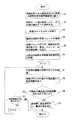
図6は、対象紙幣が偽造防止対策として磁気インクのみが採用されている紙幣である場合の真偽判別及び計数のフローチャートを示すもので、以下これに基づいて本発明に係る紙幣計数機による真偽判別等の手順を説明する。なお、本発明の実施の形態では、判別原理の異なる複数種類の真偽判別手段の例として、磁気インク検出、蛍光反応検出、スレッド検出、赤外インク検出を採用している。
【0022】
ところで、本発明における検出出力の有無について、各検出器ごとに定義しておくこととする。
【0023】
磁気インク検出において、検出出力が有るとは、文字通り磁気成分により出力信号が能動的に検知された場合を指す。
【0024】
蛍光反応検出において、検出出力が有るとは、紫外線照射光源から紙幣に紫外線が照射されて、紙幣全面からの蛍光反応が受光素子で検知された場合を指す。つまり、紙幣の紙質又は漂白剤に起因する蛍光反応を対象としている。
【0025】
スレッド検出において、検出出力が有るとは、文字通りスレッドによって引き起こされる静電容量の変化や磁束の変化が能動的に検知された場合を指す。
【0026】
赤外インク検出において、検出出力が有るとは、赤外線照射光源から照射された赤外線が紙幣に印刷された赤外吸収インクによって赤外線が吸収される結果、受光素子が赤外線を検知しない場合を指す。
【0027】
最初に図1の紙幣載置部10に、対象紙幣として、偽造防止対策として磁気インクのみが採用されている紙幣の束が置かれる(ステップS1)。次いで図4で示される判別モード選択手段32を操作して4つの検出器をすべて選択する(ステップS2)。なお、オート選択モードに設定することにより、電源投入時に自動的にすべての真偽判別手段が選択されるようにしてもよい。この場合は、紙幣の種類によっては不要となる真偽判別手段を判別モード選択手段32によって無効とするようにしてもよい。図4に示される計数スタートボタン34を押下すると(ステップS3)、紙幣載置部10に置かれた紙幣のうち最下層のものが最初の紙幣として判別ブロックへ送られる(ステップS4)。なお、ステップS3において、紙幣載置部10に紙幣を置くと自動的に計数がスタートするオートスタートモードに設定しておけば、計数スタートボタン34を押下しなくてもよい。
【0028】
この場合、偽造防止対策として磁気インクのみが採用されている紙幣であり、赤外線吸収インクも存在しないので、赤外線が照射されても赤外線が吸収されず従って赤外線がそのまま紙幣を透過し、赤外線が検知されるが、前記定義により検出出力無しとして扱われる。判別ブロックの中の磁気検出器のみが出力有りを検出出力し、蛍光検出器/スレッド検出器/赤外検出器は出力無しを検出出力する(ステップS5)。次いでこの出力結果(条件)が判別条件記憶手段110に記憶される(ステップS6)。次に、2枚目の紙幣が繰出され判別ブロックへ送られ(ステップS7)、該紙幣についての各検出器毎の検出有無が出力され(ステップS8)、条件合致比較手段120によって合致するか否かの比較がされる(ステップS9)。ここで合致すれば、紙幣載置部10に紙幣が残っていることを条件として(ステップS11)、ステップ7に戻り3枚日の紙幣処理へと移行するが、合致しないと判断されれば制御部へ通知し、通知を受けた制御部は表示部に偽札表示することを指示すると共に搬送手段の停止を指示する(ステップS10)。
【0029】
以上は対象紙幣を偽造防止対策として磁気インクのみが採用されている紙幣としたときの真偽判別及び計数の流れを説明したものであるが、これ以外の偽造防止対策を施されている紙幣についても同様であることは言うまでもない。
【0030】
本発明に係る紙幣計数機は、最初に繰出された紙幣の偽造防止対策上の特徴を読みとり、その情報に基づいて真偽判別を自動的に行うように構成されているので、操作者による真偽判別条件の設定を必要とせずに、世界各国の紙幣処理に利用可能である。
【0031】
特にユーロ圏では、自国紙幣と、共通紙幣であるユーロ紙幣の共存という宿命があるが、本発明による紙幣処理機の採用により、これら種類の異なる紙幣を種類毎に区分して処理するだけで、種類に応じた真偽判別条件の設定をせずに処理することができる。また、複数の外貨紙幣を扱う銀行においても、同様なことが言える。
なお、図2に示すスタッカセンサ80を紙幣判別条件のリセットに利用することも可能である。すなわち、集積部20に紙幣がある間は、直前の紙幣判別条件を保持しておき、集積部20に紙幣が無くなると処理が完了したものと判断して紙幣判別条件をクリアするのである。このようにすることで、紙幣載置部10に置かれた紙幣の全てが集積部に送られて無くなった場合であって、同一種類の紙幣を更に追加して処理したい場合には、集積部から紙幣を取り出さないことで判別条件を維持できる。
【0032】
【発明の効果】
以上に示したように、請求項1乃至3の発明によれば、最初に処理される紙幣に対して複数種類の検出器の各々について出力有り/出力無しを検知し、その結果と2枚目以降の紙幣の検出出力との比較を行うことで真偽判別を行うように構成されているので、対象紙幣がいかなる偽造防止対策が講じられていたとしても、操作者による対象紙幣の偽造防止対策毎の真偽判別条件設定が不要となり、操作性が向上する。
【0033】
請求項4の発明によれば、偽造の疑いのある紙幣を発見した際には搬送を停止させるので、該偽造の疑いのある紙幣と他の紙幣(真券と判別された紙幣)との選別を容易に行うことができる。
【0034】
請求項5の発明によれば、対象紙幣が1枚しか無くて2枚目以降の紙幣が存在しないがゆえに真偽判定条件の比較ができず、そのため真偽の判定が自動的には行えないときに、操作者に対し、当該唯一の対象紙幣が反応した(つまり、出力があった)検出器の種類を表示により知らせることで真偽判定の便宜を図ることができる。
【0035】
さらに詳しく言えば、そもそも本発明は、最初に処理される紙幣に基づいて真偽判別条件を自動設定するようにしている。従って、最初に処理される紙幣がたまたま偽造紙幣であった場合には、2枚目以降の真券紙幣が偽造の疑い有りとの判別結果が出されることになる。しかしながら、最初に処理される紙幣により出力のあった検出器の種類を表示により知らせるようにしているので、操作者が対象紙幣についての真偽情報を予め了知していることを条件として、操作者はこの情報により、該最初に処理された紙幣が偽造紙幣であることを知ることが可能となる。
【0036】
請求項6乃至8の発明は請求項1の発明を簡略化して単一の真偽判別手段として構成した場合のものである。最初の紙幣で該単一の真偽判別手段で出力が検出されれば、2枚目以降の紙幣について同様な出力があれば、真券と判断する。一方最初の紙幣で該単一の真偽判別手段で出力が検出されなければ、2枚目以降の紙幣について出力が検出されたときに該紙幣を偽造券と判断することになるが、むしろ対象紙幣の中に種類の異なる紙幣が混入していた場合の発見に役立てる使い方の応用が考えられる。
【図面の簡単な説明】
【図1】本発明に係る紙幣計数機の実施例の外観図である。
【図2】紙幣計数機の内部構造を示す縦断面図である。
【図3】真偽判別のための検出器の配置等を示すものである。
【図4】操作/表示部の一例を示す図である。
【図5】本発明に係る紙幣計数機の構成を示すブロック図である。
【図6】対象紙幣が偽造防止対策として磁気インクのみが採用されている紙幣である場合の、真偽判別及び計数のフローチャートである。
【符号の説明】
10 紙幣載置部
20 集積部
30 操作/表示部
31 表示部
32 判別モード選択手段
33 AUTO STARTキー
34 計数スタートボタン(RESTARTキー)
40 羽根車
50 繰出ローラ
60 搬送ローラ(搬送手段)
70 真偽判別ブロック
71 磁気検出器
72 蛍光検出器
73 スレッド検出器
74 赤外検出器
80 スタッカセンサ
100 紙幣
110 判別条件記憶手段
120 条件合致比較手段[0001]
BACKGROUND OF THE INVENTION
The present invention relates to a bill counter, which mainly includes a plurality of types of authenticity determination means, and an operator determines which of the authenticity determination means should determine based on the characteristics of the target banknote. The present invention relates to a bill counter capable of authenticating without setting operation.
[0002]
[Prior art]
As banknote counters having a bill authenticity discrimination function, two types of banknote counters are known.
[0003]
The first type of banknote counter specifies the denomination of the target banknote and performs authenticity determination based on the characteristics of the specified denomination.
[0004]
On the other hand, the second type performs true / false determination without specifying the denomination, and performs the true / false determination based on the feature independent of the denomination.
[0005]
Those belonging to the second type and used in combination with a plurality of different types of authenticity determination means are known, such as US Pat. No. 4,114,804, and Japan related to the same invention based on the priority claim. A banknote counter disclosed in Japanese Patent Application Laid-Open No. 53-44089, which is a patent application to is known.
[0006]
These gazettes disclose magnetic ink detection means and fluorescence reaction detection means as authenticity determination means, when magnetic ink is detected for a banknote to be examined and no fluorescence reaction is detected. The bill to be examined is judged as a genuine note.
[0007]
[Problems to be solved by the invention]
In the first place, as described in the specification, the above-mentioned publication exclusively assumes US banknotes, and is a combination of authenticity determination means selected according to the characteristics of US banknotes. . That is, it is a discrimination method based on the property that magnetic ink is used for US banknotes (genuine bills) and no fluorescence reaction is detected.
[0008]
By the way, there is a demand for a bill counter having a true / false discrimination function that can be used for any bill in countries around the world. In countries around the world, for example, in addition to the above, an infrared Various measures such as the use of absorbing ink and thread weaving have been made, and in order to target banknotes for which anti-counterfeiting measures have been taken, it is not sufficient to detect magnetic ink or fluorescence reaction as described above. Of course, it is necessary to employ an infrared absorbing ink detector or a thread detector.
[0009]
By installing a true / false discrimination function corresponding to these anti-counterfeiting measures, a general-purpose banknote counter capable of handling banknotes in many countries can be obtained. However, in order to make full use of this general-purpose banknote counter, the operator must know in advance the contents of the counterfeit prevention measures for the banknotes to be examined, and then perform the setting operation of the authenticity discrimination means corresponding to the counterfeit prevention measures. Since it is necessary to do this, a complicated setting operation is forced and it becomes inconvenient. The present invention has been made in view of such circumstances, and an object thereof is to provide a banknote counter that does not require a setting operation by an operator for authenticity determination means corresponding to anti-counterfeiting measures.
[0010]
[Means for Solving the Problems]
The present invention relates to a bill counter that does not require a setting operation by an operator for authenticity determination means corresponding to counterfeit prevention measures, and the above-described object of the present invention is a bill placement unit on which a plurality of bills are placed. A feeding means for feeding the banknotes placed on the banknote placement section one by one; a transporting means for transporting the banknotes fed by the feeding means to the stacking section; the feeding means and the stacking A bill counter having a true / false discriminating means for discriminating whether the bill is true or false, wherein the true / false discriminating means comprises a plurality of types of detectors having different discrimination principles. A discrimination condition storage means for detecting the presence or absence of output in each of a plurality of types of detectors having different discrimination principles and storing the detection result for the first bill fed out, and the second and subsequent bills Discrimination principle for A condition matching comparison means for comparing the detection results of different types of detectors with the detection results stored in the discrimination condition storage means, and the results of comparison result in the detection of a plurality of types of detectors having different discrimination principles; This is achieved by a bill counter configured to determine that a bill is counterfeit when at least one of the results does not match.
[0011]
In addition, the above-mentioned object of the present invention is about the second and subsequent banknotes in the detector for the detectors that did not output the banknotes fed out first among the multiple types of detectors having different discrimination principles. Output from the information for true / false discrimination, or a plurality of types of detectors with different discrimination principles can detect one of magnetic ink detection, fluorescence reaction detection, thread detection, and infrared ink detection. By comprising, it is achieved more effectively.
[0012]
Further, as a result of the authenticity determination by the detector, when the determination condition is inconsistent, the transporting means is controlled to stop, or the display unit has a display unit and the detection of the first fed banknote is performed. This is achieved more effectively by a bill counter configured to display on the display unit the detector related to the output that was output.
[0013]
Still further, the object of the present invention is to provide a bill placing portion on which a plurality of bills are placed, a feeding means for feeding the bills placed on the bill placing portion one by one, and the feeding means. In a banknote counter having transport means for transporting the fed banknotes to a stacking unit, and authenticity determining means for determining authenticity of the banknotes located between the feeding unit and the stacking unit, A determination condition storage means for configuring the authenticity determination means with a single type of detector, detecting presence / absence of output in the authenticity determination means for the first fed banknote, and storing the detection result And a condition matching comparison means for comparing the presence / absence of output in the detector with respect to the second and subsequent bills and information on the presence / absence of output for the first bill stored in the discrimination condition storage means, As a result, the presence or absence of output Can be conveniently accomplished by the configuration bill counting machine to determine a counterfeit bill if no match.
[0014]
Furthermore, it can be achieved more effectively by controlling the stop of the conveying means when a condition mismatch is detected as a result of the authenticity determination by the authenticity determination means.
[0015]
DETAILED DESCRIPTION OF THE INVENTION
Embodiments of a bill counter according to the present invention will be described below with reference to the drawings.
[0016]
FIG. 1 is an external view of an embodiment of a bill counter according to the present invention, where a
[0017]
FIG. 2 is a longitudinal sectional view showing the internal structure of the bill counter. In the figure,
[0018]
FIG. 3 shows the arrangement of detectors for authenticity determination. FIG. 3A is a diagram showing the arrangement of the
[0019]
FIG. 4 is a diagram showing an example of the operation /
[0020]
FIG. 5 is a block diagram showing the configuration of the banknote counter according to the present invention. In the figure, the discrimination block is composed of a total of four types of detectors. For example, a known magnetic head can be used as the
[0021]
FIG. 6 shows a flowchart of authenticity determination and counting when the target banknote is a banknote in which only magnetic ink is adopted as a counterfeit prevention measure. Based on this, the authenticity by the banknote counter according to the present invention is shown below. A procedure such as false determination will be described. In the embodiment of the present invention, magnetic ink detection, fluorescence reaction detection, thread detection, and infrared ink detection are employed as examples of a plurality of types of authenticity determination means having different determination principles.
[0022]
By the way, the presence or absence of the detection output in the present invention is defined for each detector.
[0023]
In magnetic ink detection, the presence of a detection output literally indicates a case where an output signal is actively detected by a magnetic component.
[0024]
In the fluorescence reaction detection, the presence of detection output refers to the case where the bill is irradiated with ultraviolet rays from the ultraviolet irradiation light source and the fluorescence reaction from the entire bill is detected by the light receiving element. That is, the fluorescent reaction caused by the paper quality of the banknote or the bleaching agent is targeted.
[0025]
In the thread detection, the presence of a detection output literally indicates a case where a change in electrostatic capacitance or a change in magnetic flux caused by the thread is actively detected.
[0026]
In infrared ink detection, the presence of detection output refers to the case where the light receiving element does not detect infrared light as a result of the infrared light being absorbed by the infrared absorbing ink printed on the banknotes.
[0027]
First, a bundle of banknotes in which only magnetic ink is adopted as a counter measure against forgery is placed on the
[0028]
In this case, the bill uses only magnetic ink as a countermeasure against counterfeiting, and there is no infrared absorbing ink, so infrared rays are not absorbed even when irradiated with infrared rays. However, it is treated as no detection output by the above definition. Only the magnetic detector in the discrimination block detects and outputs the output, and the fluorescence detector / sled detector / infrared detector detects and outputs the absence of output (step S5). Next, this output result (condition) is stored in the discrimination condition storage means 110 (step S6). Next, the second banknote is fed out and sent to the discrimination block (step S7), and the presence / absence of detection for each detector for the banknote is output (step S8). Are compared (step S9). If it matches here, on condition that the banknote remains in the banknote mounting part 10 (step S11), it will return to step 7 and will transfer to the banknote processing of the 3rd sheet | seat, but if it is judged that it does not match, it will be controlled. The control unit that has received the notification instructs the display unit to display a counterfeit bill and instructs the transportation unit to stop (step S10).
[0029]
The above is a description of the authenticity determination and counting flow when the target banknote is a banknote in which only magnetic ink is adopted as a counterfeit prevention measure. It goes without saying that the same applies.
[0030]
The bill counter according to the present invention is configured to read the features of the bills that have been paid out for preventing counterfeiting, and automatically perform authenticity determination based on the information. It can be used for banknote processing in countries around the world without the need for setting false discrimination conditions.
[0031]
Especially in the euro zone, there is a fate of coexistence of the home banknotes and the euro banknotes that are common banknotes, but by adopting the banknote processing machine according to the present invention, it is only necessary to classify and process these different banknotes by type, Processing can be performed without setting authenticity determination conditions according to the type. The same applies to banks that handle multiple foreign currency banknotes.
Note that the
[0032]
【The invention's effect】
As described above, according to the first to third aspects of the present invention, the presence / absence of output is detected for each of a plurality of types of detectors with respect to the first processed banknote, and the result and the second sheet are detected. Since it is configured to determine authenticity by comparing it with the detection output of subsequent banknotes, even if any counterfeit prevention measures have been taken for the target banknotes, countermeasures to prevent counterfeiting of the target banknotes by the operator It is not necessary to set the true / false determination condition every time, and the operability is improved.
[0033]
According to the invention of claim 4, since the conveyance is stopped when a banknote suspected of forgery is found, the banknote suspected of counterfeiting and other banknotes (banknotes determined to be authentic) are selected. Can be easily performed.
[0034]
According to the invention of
[0035]
More specifically, in the first place, the present invention automatically sets the authenticity determination condition based on the first processed bill. Therefore, if the first processed banknote happens to be a forged banknote, a determination result is issued that the second and subsequent genuine banknotes are suspected of being counterfeited. However, since the type of detector output by the first processed banknote is notified by display, the operation is performed on the condition that the operator knows the authenticity information about the target banknote in advance. By this information, the person can know that the first processed banknote is a counterfeit banknote.
[0036]
The inventions of claims 6 to 8 are the cases where the invention of
[Brief description of the drawings]
FIG. 1 is an external view of an embodiment of a bill counter according to the present invention.
FIG. 2 is a longitudinal sectional view showing an internal structure of the bill counter.
FIG. 3 shows the arrangement of detectors for authenticity determination.
FIG. 4 is a diagram illustrating an example of an operation / display unit.
FIG. 5 is a block diagram showing a configuration of a banknote counter according to the present invention.
FIG. 6 is a flowchart of authenticity determination and counting when the target banknote is a banknote in which only magnetic ink is adopted as a counterfeit prevention measure.
[Explanation of symbols]
DESCRIPTION OF
40
70
Claims (7)
Translated fromJapanese前記真偽判別手段は、判別原理の異なる複数種類の検出器で構成されるとともに、最初に繰出された前記紙幣について該判別原理の異なる複数種類の検出器のそれぞれにおいて出力の有無を検知し、かつ、その検知結果を記憶する判別条件記憶手段と、2枚目以降の紙幣に対する前記判別原理の異なる複数種類の検出器における検知結果と該判別条件記憶手段に記憶されている検知結果とを比較する条件合致比較手段とを備え、比較の結果、前記判別原理の異なる複数種類の検出器における検知結果のうち少なくとも一つが一致しなかった場合に偽造紙幣と判断するように構成されていることを特徴とする紙幣計数機。A banknote placement section on which a plurality of banknotes are placed, a feeding means for feeding the banknotes placed on the banknote placement section one by one, and the banknotes fed by the feeding means to the stacking section. A banknote counter having transporting means for transporting, and authenticity determining means for determining authenticity of the banknote located between the feeding means and the stacking unit,
The authenticity determination means includes a plurality of types of detectors having different determination principles, and detects the presence or absence of output in each of the plurality of types of detectors having different determination principles for the banknotes that are initially fed, In addition, the discrimination condition storage means for storing the detection result is compared with the detection results stored in the discrimination condition storage means for a plurality of types of detectors having different discrimination principles for the second and subsequent bills. And a condition matching comparison means configured to determine that the bill is a counterfeit bill when at least one of the detection results of the plurality of types of detectors having different discrimination principles does not match as a result of the comparison. Characteristic bill counting machine.
前記真偽判別手段を単一種類の検出器で構成し、最初に繰出された紙幣に対して前記真偽判別手段における出力の有無を検知するとともに、その検知結果を記憶する判別条件記憶手段を備え、2枚目以降の紙幣に対する該検出器における出力の有無と前記判別条件記憶手段に記憶されている最初の紙幣についての出力の有無の情報とを比較する条件合致比較手段とを備え、比較の結果、出力の有無が一致しなかった場合に偽造紙幣と判断するように構成されていることを特徴とする紙幣計数機。A banknote placement section on which a plurality of banknotes are placed, a feeding means for feeding the banknotes placed on the banknote placement section one by one, and the banknotes fed by the feeding means to the stacking section. In a banknote counter having transporting means for transporting and authenticity determining means for determining authenticity of the banknotes located between the feeding means and the stacking unit,
A determination condition storage means for configuring the authenticity determination means with a single type of detector, detecting presence / absence of output in the authenticity determination means for the first fed banknote, and storing the detection result And a condition matching comparison means for comparing the presence / absence of output in the detector with respect to the second and subsequent bills and information on the presence / absence of output for the first bill stored in the discrimination condition storage means, As a result, when the presence or absence of output does not correspond, it is comprised so that it may be judged that it is a forged banknote, The banknote counter characterized by the above-mentioned.
Priority Applications (5)
| Application Number | Priority Date | Filing Date | Title |
|---|---|---|---|
| JP2001076873AJP4320127B2 (en) | 2001-03-16 | 2001-03-16 | Bill counter |
| EP02075948AEP1241637A3 (en) | 2001-03-16 | 2002-03-08 | Bill counter |
| US10/097,114US6908029B2 (en) | 2001-03-16 | 2002-03-12 | Bill counter |
| KR1020020013834AKR100866353B1 (en) | 2001-03-16 | 2002-03-14 | Bill counter |
| CNB021074437ACN1245700C (en) | 2001-03-16 | 2002-03-15 | Money checking machine |
Applications Claiming Priority (1)
| Application Number | Priority Date | Filing Date | Title |
|---|---|---|---|
| JP2001076873AJP4320127B2 (en) | 2001-03-16 | 2001-03-16 | Bill counter |
Publications (2)
| Publication Number | Publication Date |
|---|---|
| JP2002279477A JP2002279477A (en) | 2002-09-27 |
| JP4320127B2true JP4320127B2 (en) | 2009-08-26 |
Family
ID=18933730
Family Applications (1)
| Application Number | Title | Priority Date | Filing Date |
|---|---|---|---|
| JP2001076873AExpired - Fee RelatedJP4320127B2 (en) | 2001-03-16 | 2001-03-16 | Bill counter |
Country Status (1)
| Country | Link |
|---|---|
| JP (1) | JP4320127B2 (en) |
Families Citing this family (3)
| Publication number | Priority date | Publication date | Assignee | Title |
|---|---|---|---|---|
| CN101529478B (en) | 2006-10-24 | 2012-06-13 | 光荣株式会社 | Bill identifier/counter |
| JP2020046712A (en)* | 2018-09-14 | 2020-03-26 | グローリー株式会社 | Printed matter inspection device and printed matter inspection method |
| CN116631111A (en)* | 2023-06-21 | 2023-08-22 | 中国工商银行股份有限公司 | Banknote checking and counting device and banknote checking and counting method |
- 2001
- 2001-03-16JPJP2001076873Apatent/JP4320127B2/ennot_activeExpired - Fee Related
Also Published As
| Publication number | Publication date |
|---|---|
| JP2002279477A (en) | 2002-09-27 |
Similar Documents
| Publication | Publication Date | Title |
|---|---|---|
| KR100866353B1 (en) | Bill counter | |
| EP0807906B1 (en) | Method and apparatus for discriminating and counting documents | |
| US5992601A (en) | Method and apparatus for document identification and authentication | |
| EP2077535B1 (en) | Bill identifier/counter | |
| WO1997030422A1 (en) | Method and apparatus for document identification | |
| US20020056605A1 (en) | Method and apparatus for document processing | |
| US7185749B2 (en) | Currency bill recycling machine | |
| JP2009238090A (en) | Paper sheet discrimination device and method | |
| US20100140148A1 (en) | Paper sheet handling machine | |
| JPH08180189A (en) | Method and device for deciding authenticity of paper sheet | |
| JP4320127B2 (en) | Bill counter | |
| KR200199843Y1 (en) | Paper money sensing device using infrared ray transmitting array module | |
| JP3599924B2 (en) | Banknote handling equipment | |
| JP3917412B2 (en) | Bill counter | |
| JPH0714048A (en) | Paper money discriminating device | |
| JPH06203243A (en) | Genuineness/counterfeit discriminating device for sheet paper or the like | |
| US9179026B2 (en) | Device for cancelling checks | |
| JP2000149086A (en) | Paper money counting and discriminating device | |
| JP2005266982A (en) | Paper money dispenser | |
| RU2736700C2 (en) | Apparatus and method for processing banknotes | |
| US8939271B2 (en) | Device for handling value documents | |
| GB2347001A (en) | Currency discriminating methods | |
| JPH01150655A (en) | Paper sheet conveyance device | |
| WO2009122503A1 (en) | Coin processor | |
| KR20170044502A (en) | Counterfeit bill detection appratus with light focusing plate |
Legal Events
| Date | Code | Title | Description |
|---|---|---|---|
| A621 | Written request for application examination | Free format text:JAPANESE INTERMEDIATE CODE: A621 Effective date:20040913 | |
| A977 | Report on retrieval | Free format text:JAPANESE INTERMEDIATE CODE: A971007 Effective date:20060525 | |
| A131 | Notification of reasons for refusal | Free format text:JAPANESE INTERMEDIATE CODE: A131 Effective date:20060613 | |
| A02 | Decision of refusal | Free format text:JAPANESE INTERMEDIATE CODE: A02 Effective date:20070227 | |
| A521 | Written amendment | Free format text:JAPANESE INTERMEDIATE CODE: A523 Effective date:20090430 | |
| A01 | Written decision to grant a patent or to grant a registration (utility model) | Free format text:JAPANESE INTERMEDIATE CODE: A01 | |
| A61 | First payment of annual fees (during grant procedure) | Free format text:JAPANESE INTERMEDIATE CODE: A61 Effective date:20090601 | |
| FPAY | Renewal fee payment (event date is renewal date of database) | Free format text:PAYMENT UNTIL: 20120605 Year of fee payment:3 | |
| R150 | Certificate of patent or registration of utility model | Free format text:JAPANESE INTERMEDIATE CODE: R150 | |
| FPAY | Renewal fee payment (event date is renewal date of database) | Free format text:PAYMENT UNTIL: 20120605 Year of fee payment:3 | |
| FPAY | Renewal fee payment (event date is renewal date of database) | Free format text:PAYMENT UNTIL: 20130605 Year of fee payment:4 | |
| FPAY | Renewal fee payment (event date is renewal date of database) | Free format text:PAYMENT UNTIL: 20130605 Year of fee payment:4 | |
| LAPS | Cancellation because of no payment of annual fees |