JP4320117B2 - Image display method and image display apparatus - Google Patents
Image display method and image display apparatusDownload PDFInfo
- Publication number
- JP4320117B2 JP4320117B2JP2000356257AJP2000356257AJP4320117B2JP 4320117 B2JP4320117 B2JP 4320117B2JP 2000356257 AJP2000356257 AJP 2000356257AJP 2000356257 AJP2000356257 AJP 2000356257AJP 4320117 B2JP4320117 B2JP 4320117B2
- Authority
- JP
- Japan
- Prior art keywords
- image
- data
- pixel
- display
- image data
- Prior art date
- Legal status (The legal status is an assumption and is not a legal conclusion. Google has not performed a legal analysis and makes no representation as to the accuracy of the status listed.)
- Expired - Fee Related
Links
Images


Classifications
- G—PHYSICS
- G06—COMPUTING OR CALCULATING; COUNTING
- G06F—ELECTRIC DIGITAL DATA PROCESSING
- G06F3/00—Input arrangements for transferring data to be processed into a form capable of being handled by the computer; Output arrangements for transferring data from processing unit to output unit, e.g. interface arrangements
- G06F3/14—Digital output to display device ; Cooperation and interconnection of the display device with other functional units
- G06F3/1423—Digital output to display device ; Cooperation and interconnection of the display device with other functional units controlling a plurality of local displays, e.g. CRT and flat panel display
- G06F3/1431—Digital output to display device ; Cooperation and interconnection of the display device with other functional units controlling a plurality of local displays, e.g. CRT and flat panel display using a single graphics controller
- G—PHYSICS
- G09—EDUCATION; CRYPTOGRAPHY; DISPLAY; ADVERTISING; SEALS
- G09G—ARRANGEMENTS OR CIRCUITS FOR CONTROL OF INDICATING DEVICES USING STATIC MEANS TO PRESENT VARIABLE INFORMATION
- G09G5/00—Control arrangements or circuits for visual indicators common to cathode-ray tube indicators and other visual indicators
- G09G5/003—Details of a display terminal, the details relating to the control arrangement of the display terminal and to the interfaces thereto
- G09G5/006—Details of the interface to the display terminal
- G—PHYSICS
- G09—EDUCATION; CRYPTOGRAPHY; DISPLAY; ADVERTISING; SEALS
- G09G—ARRANGEMENTS OR CIRCUITS FOR CONTROL OF INDICATING DEVICES USING STATIC MEANS TO PRESENT VARIABLE INFORMATION
- G09G2310/00—Command of the display device
- G09G2310/02—Addressing, scanning or driving the display screen or processing steps related thereto
- G09G2310/0202—Addressing of scan or signal lines
- G09G2310/0221—Addressing of scan or signal lines with use of split matrices
- G—PHYSICS
- G09—EDUCATION; CRYPTOGRAPHY; DISPLAY; ADVERTISING; SEALS
- G09G—ARRANGEMENTS OR CIRCUITS FOR CONTROL OF INDICATING DEVICES USING STATIC MEANS TO PRESENT VARIABLE INFORMATION
- G09G2340/00—Aspects of display data processing
- G09G2340/04—Changes in size, position or resolution of an image
- G09G2340/0407—Resolution change, inclusive of the use of different resolutions for different screen areas
- G09G2340/0428—Gradation resolution change
- G—PHYSICS
- G09—EDUCATION; CRYPTOGRAPHY; DISPLAY; ADVERTISING; SEALS
- G09G—ARRANGEMENTS OR CIRCUITS FOR CONTROL OF INDICATING DEVICES USING STATIC MEANS TO PRESENT VARIABLE INFORMATION
- G09G3/00—Control arrangements or circuits, of interest only in connection with visual indicators other than cathode-ray tubes
- G09G3/20—Control arrangements or circuits, of interest only in connection with visual indicators other than cathode-ray tubes for presentation of an assembly of a number of characters, e.g. a page, by composing the assembly by combination of individual elements arranged in a matrix no fixed position being assigned to or needed to be assigned to the individual characters or partial characters
- G09G3/2007—Display of intermediate tones
- G09G3/2074—Display of intermediate tones using sub-pixels
- G—PHYSICS
- G09—EDUCATION; CRYPTOGRAPHY; DISPLAY; ADVERTISING; SEALS
- G09G—ARRANGEMENTS OR CIRCUITS FOR CONTROL OF INDICATING DEVICES USING STATIC MEANS TO PRESENT VARIABLE INFORMATION
- G09G3/00—Control arrangements or circuits, of interest only in connection with visual indicators other than cathode-ray tubes
- G09G3/20—Control arrangements or circuits, of interest only in connection with visual indicators other than cathode-ray tubes for presentation of an assembly of a number of characters, e.g. a page, by composing the assembly by combination of individual elements arranged in a matrix no fixed position being assigned to or needed to be assigned to the individual characters or partial characters
- G09G3/34—Control arrangements or circuits, of interest only in connection with visual indicators other than cathode-ray tubes for presentation of an assembly of a number of characters, e.g. a page, by composing the assembly by combination of individual elements arranged in a matrix no fixed position being assigned to or needed to be assigned to the individual characters or partial characters by control of light from an independent source
- G09G3/36—Control arrangements or circuits, of interest only in connection with visual indicators other than cathode-ray tubes for presentation of an assembly of a number of characters, e.g. a page, by composing the assembly by combination of individual elements arranged in a matrix no fixed position being assigned to or needed to be assigned to the individual characters or partial characters by control of light from an independent source using liquid crystals
- G09G3/3607—Control arrangements or circuits, of interest only in connection with visual indicators other than cathode-ray tubes for presentation of an assembly of a number of characters, e.g. a page, by composing the assembly by combination of individual elements arranged in a matrix no fixed position being assigned to or needed to be assigned to the individual characters or partial characters by control of light from an independent source using liquid crystals for displaying colours or for displaying grey scales with a specific pixel layout, e.g. using sub-pixels
- G—PHYSICS
- G09—EDUCATION; CRYPTOGRAPHY; DISPLAY; ADVERTISING; SEALS
- G09G—ARRANGEMENTS OR CIRCUITS FOR CONTROL OF INDICATING DEVICES USING STATIC MEANS TO PRESENT VARIABLE INFORMATION
- G09G5/00—Control arrangements or circuits for visual indicators common to cathode-ray tube indicators and other visual indicators
- G09G5/02—Control arrangements or circuits for visual indicators common to cathode-ray tube indicators and other visual indicators characterised by the way in which colour is displayed
- G09G5/028—Circuits for converting colour display signals into monochrome display signals
Landscapes
- Engineering & Computer Science (AREA)
- Theoretical Computer Science (AREA)
- Physics & Mathematics (AREA)
- General Physics & Mathematics (AREA)
- Computer Graphics (AREA)
- Human Computer Interaction (AREA)
- General Engineering & Computer Science (AREA)
- Computer Hardware Design (AREA)
- Liquid Crystal Display Device Control (AREA)
- Control Of Indicators Other Than Cathode Ray Tubes (AREA)
- Controls And Circuits For Display Device (AREA)
Description
Translated fromJapanese【0001】
【発明の属する技術分野】
本発明は、モノクロディスプレイを用いた画像表示の技術分野に属し、詳しくは、サブピクセル構造を利用した高階調な画素表示を、1つのビデオカードで複数のモノクロディスプレイに行うことを可能にする画像表示方法および画像表示装置に関する。
【0002】
【従来の技術】
超音波診断装置、CT診断装置、MRI診断装置、X線診断装置、FCR(富士コンピューテッドラジオグラフィー)等の医療用診断装置で撮影(測定)された医療用画像は、必要に応じて各種の画像処理を施された後、通常は、レーザプリンタやサーマルプリンタ等のプリンタによって、フィルム状の記録材料に可視像として再生されて、ハードコピーとして出力される。
医療用画像を再生したフィルムは、医療現場において、シャーカステンと呼ばれるライトボックスを用いて観察され、各種の診断に用いられる。
【0003】
近年では、医療用診断装置で撮影された医療用画像を、ディスプレイにソフトコピーとして再生して、診断することも行われている。
また、現在は、医療用診断装置のディスプレイとしては、CRT(Cathode Ray Tube)が主流であるが、小型化が容易である、薄い、軽量である等、非常に多くの利点を有することから、近年では、液晶ディスプレイ(LCD)も、医療用診断装置のディスプレイとしての採用が検討されている。
【0004】
周知のように、LCDに用いられるLCDパネルはデジタル駆動が可能である。近年では、DVI(Digital Visual Interface)のようなデジタル信号をディスプレイに転送できるインターフェイス(i/f)も汎用化され、LCDパネルを用いて、デジタル−アナログの信号変換による劣化のない、高画質の画像表示が行われている。
また、最も汎用されているデジタルの画像i/fであるDVIでは、TMDS(transition minimized differential signaling) というシリアルのデータ転送方式が採用されている。
【0005】
このような、DVIによるデジタルの画像データ転送を利用するシステムにおいて、R(赤)、G(緑)およびB(青)の各8ビットのカラー画像を表示する場合には、UXGA(1600×1200画素)〜HDTV(1920×1080画素)までしか対応できず、これよりも高画素のディスプレイ、例えば、QXGA(2048×1536画素)のカラーLCDパネルに画像を表示する際には、画像データの転送が間に合わない。
そのため、QXGAのデジタルカラーLCDパネルにDVIを用いて画像データを転送し、画像を表示する際には、LCDパネルを2分割して、画像を表示することが行われている。図3にその一例を概念的に示す。
【0006】
図3に示されるシステムにおいては、LCD100と、LCD100に画像データを供給するパーソナルコンピュータ(PC)等に搭載されるビデオカード30とが、DVIによって接続されている。
LCD100に搭載されるQXGAのカラーのLCDパネル102は、1024×1536画素ずつの右画面102Rと左画面102Lに分割されている。
また、ビデオカード30は、第1リンク32aと第2リンク32bの2つの出力系統を有し、第1リンク32aは右画面102Rに、第2リンク32bは左画面102Lに対応する。さらに、DVIによる画像データの転送を行うビデオカード30の各リンクは、それぞれ、R画像データ、G画像データおよびB画像データに対応する3つのチャンネルと、クロック信号の出力とを有する。
【0007】
このような構成の下、ビデオカード30は、第1リンク32aから、LCD100の右画面102Rに対応するR、GおよびBの各8ビットの画像データとクロック信号を転送し、また、第2リンク32bから、左画面102Lに対応するR、GおよびBの各8ビットの画像データとクロック信号を転送する。
前述のように、LCDパネル102の右画面102Rおよび左画面102Lの画素数は、1024×1536画素でUXGA以下である。従って、DVIでも十分に画像データの転送が間に合い、QXGAのカラーのLCDパネル102に画像を表示することができる。
【0008】
ここで、PC等で標準的に用いられているPCI(peripheral component interconnect)バスに挿入されるビデオカードは、基板やコネクタサイズ等の関係で、DVIコネクタを2個までしか実装することができない。
従って、現在、QXGAのカラーのLCDパネルにDVIで画像データを転送して画像を表示する際には、1枚のLCDパネル(1ヘッド)に付き、1つのビデオカード(1カード)が必要であり(1カード1ヘッドのシステム)、2枚のLCDパネルに画像を表示する際には、2つのビデオカードが必要である(2カード2ヘッドのシステム)。
【0009】
ところで、前述のような医療用画像のうち、例えばFCRやX線診断装置で撮影された診断画像は、モノクロ画像で表示されるのが通常である。
また、カラーLCDパネルのカラーフィルタを無色化することでモノクロ化されたモノクロLCDパネルも実用化されている。
【0010】
ここで、カラーのLCDパネルは、1画素についてR、GおよびBのサブピクセルを有するので、これをモノクロ化したモノクロLCDパネルも、1画素について、3つのサブピクセルを有する。また、このようなモノクロLCDパネルで画像を表示する際には、通常は、1画素の全サブピクセルを同じ画像データで駆動(変調)する。
モノクロLCDパネルでは、これを利用して、DVIによる画像データ転送を用いて、1つのビデオカードで2枚のQXGAのパネルに画像を表示する、1カード2ヘッドのシステムの実用化が検討されている。その一例の概念図を、図4に示す。
【0011】
前述のように、DVIに対応するビデオカード30は、第1リンク32aおよび第2リンク32bの2系統の出力を有する。図示例のシステムにおいては、第1リンク32aには1台目のモノクロLCD110が、第2リンク32bには2台目のモノクロLCD112が、それぞれ接続されている。また、先の例と同様、両者はDVIによって接続されている。
なお、図4において、2台目のモノクロLCD112は、1台目のモノクロLCD110と同じであるので、代表してモノクロLCD110を詳細に示す。
【0012】
モノクロLCD110(112)のモノクロLCDパネル114は、前述のように、カラーLCDパネルの色フィルタを無色化することでモノクロ化したQXGAのパネルで、先のカラーLCDパネルと同様、1024×1536画素ずつの右画面114Rと左画面114Lとに分割される。
また、モノクロLCD110は、右画面114Rに対応する画像データの展開手段116R、および、左画面114Lに対応する画像データの展開手段116Lを有する。
【0013】
前述のように、モノクロLCDパネル114は、カラーLCDパネルのR、GおよびBのサブピクセルに対応して、3つのサブピクセル(以下、第1ピクセル(1pix)、第2ピクセル、および第3ピクセルとする)を有し、各サブピクセルを同じ画像データで駆動することで、モノクロ画像を表示する。
従って、1画素について1つの画像データを転送して、3つのサブピクセルに展開すれば、モノクロLCDパネル114に画像を表示できる。
【0014】
図示例においては、ビデオカード30の第1リンク32a(第2リンク32b)のうち、R画像データに対応するチャンネルは右画面114Rの展開手段116Rに、B画像データに対応するチャンネルは左画面114Lに対応する展開手段116Lに、それぞれ8ビットのモノクロの画像データを転送する。
なお、本例においてはG画像データに対応するチャンネルは使用しない。
【0015】
画像データを受けた展開手段116Rは、この画像データを展開して(複製して)、8ビットの同じ画像データを3つ生成して、右画面114Rの対応画素の第1ピクセル、第2ピクセル、および第3ピクセルの画像データとしてモノクロLCDパネル114(そのドライバ)に供給し、画像が表示される。同様に、展開手段116Lも、供給された画像データを展開して8ビットの同じ画像データを3つ生成し、左画面114Lの対応画素の第1ピクセル、第2ピクセル、および第3ピクセルの画像データとしてモノクロLCDパネル114に供給する。
【0016】
すなわち、この方法によれば、1つのリンクの2チャンネルを用いることにより、1枚のQXGAのモノクロLCDパネル114に画像を表示できる。
従って、ビデオカード30が有する2つのリンクを両方とも用いれば、2枚のモノクロLCDパネル114に画像を表示することができ、QXGAのモノクロLCDパネルで、DVIによる画像データ転送を用いて、1カード2ヘッドのシステムを実現することができる。
【0017】
周知のように、医療用途においては、同一患者の異なる部位の撮影画像や、過去と現在の撮影画像等、多数の画像を表示して、比較しながら診断を行う場合が多い。そのため、画像を縦表示(ポートレート)にすると共に、モノクロLCD(モノクロLCDパネル)を2台並べて使用するような用途が多い。
このような用途においては、1カード2ヘッドのシステムは、ビデオカードが1台で済むので、コスト的に有利である。
【0018】
【発明が解決しようとする課題】
ところで、このモノクロLCDパネルのように、サブピクセルを有するモノクロディスプレイにおいては、本出願人にかかる特開平11−311971号や同11−352954号等の各公報に開示されるように、各サブピクセルを個々に変調することにより、高階調化を図ることができる。
例えば、カラーLCDのカラーフィルタを単色化した前記モノクロLCDパネルにおいては、各サブピクセルを8ビット(256階調)で駆動できる場合であれば、3つのサブピクセルを合計した1画素で、9.5ビット(766階調)相当の階調表現を行うことが可能である。
医療用の用途では、正確な診断を行うために、より高階調で高画質な画像が要求されるため、この方法は、非常に有利である。
【0019】
ここで、この方法を用いて高階調化する場合に、例えば、前記3つのサブピクセルを有するモノクロLCDパネルで9.5ビットを表現する場合であれば、3つのサブピクセルを、個々に独立して、8ビットで駆動する必要がある。
従って、この場合に、DVIを用いてデータを転送し、QXGAのモノクロLCDパネルに画像を表示する場合には、図3に示されるカラーのLCDパネル102の場合と同様の方法で画像データを転送する必要がある。
【0020】
すなわち、このようにして、サブピクセルを用いて高階調化を図る際には、3つのサブピクセルを同じ画像データで駆動する図4に示される場合のように、1カード2ヘッドのシステムを実現することができない。そのため、2枚のモノクロLCDパネルに画像を表示する場合には、2カード2ヘッドとせざるを得ず、コストが高くなってしまう。
【0021】
本発明の目的は、前記従来技術の問題点を解決することにあり、デジタルのインターフェイスおよびサブピクセル構造を有するモノクロLCDパネルに画像を表示する際に、パネルの画素数に対してi/fの転送レートが不十分である場合にも、データの転送量を低減することで画像データの転送を可能にして、画像表示を行うことができ、例えば、1つのビデオカードからDVIによって画像データを転送して、2枚の8ビットのQXGAのモノクロLCDパネルに画像を表示する1カード2ヘッドのシステムにおいて、サブピクセルを利用した9.5ビットの高階調画像を表示することを可能にする、画像表示方法および画像表示装置を提供することにある。
【0022】
【課題を解決するための手段】
前記目的を達成するために、本発明の画像表示方法は、デジタルのインターフェースならびに1画素について複数のサブピクセルを備えたサブピクセル構造を有するモノクロディスプレイに画像を表示するに際し、入力画像データを前記モノクロディスプレイの各画素の複数のサブピクセルに分割することにより、これら複数のサブピクセルにそれぞれ対応すると共に前記モノクロディスプレイにおける画像表示のビット数と同じビット数の複数の変換データを作成し、前記モノクロディスプレイの各画素の複数のサブピクセルのうち、1つのサブピクセルに対してはこのサブピクセルに対応する前記変換データからなる基準データを、その他のサブピクセルに対してはそれぞれのサブピクセルに対応する前記変換データと前記基準データとの差分からなる1ビットの転送用画像データをそれぞれ生成して前記モノクロディスプレイに転送し、前記モノクロディスプレイにおいて、前記1つのサブピクセルに対する基準データに前記その他のサブピクセルに対する1ビットの転送用画像データを加算することにより前記その他のサブピクセルに対して前記基準データと同じビット数の表示用画像データを生成し、前記基準データ及び前記表示用画像データを用いて前記入力画像データのビット数に対応する諧調の画像を表示することを特徴とする画像表示方法を提供する。
【0023】
また、本発明の画像表示装置は、デジタルのインターフェースならびに1画素について複数のサブピクセルを備えたサブピクセル構造を有するモノクロディスプレイと、前記モノクロディスプレイにデジタルの画像データを転送する画像データ転送部とを有し、かつ、前記画像データ転送部は、入力画像データを前記モノクロディスプレイの各画素の複数のサブピクセルに分割することにより、これら複数のサブピクセルにそれぞれ対応すると共に前記モノクロディスプレイにおける画像表示のビット数と同じビット数の複数の変換データを作成し、前記モノクロディスプレイの各画素の複数のサブピクセルのうち、1つのサブピクセルに対してはこのサブピクセルに対応する前記変換データからなる基準データを、その他のサブピクセルに対してはそれぞれのサブピクセルに対応する前記変換データと前記基準データとの差分からなる1ビットの転送用画像データをそれぞれ生成する手段を有し、この転送用画像データと基準データを前記モノクロディスプレイに転送し、さらに、前記モノクロディスプレイは、前記1つのサブピクセルに対する基準データに前記その他のサブピクセルに対する1ビットの転送用画像データを加算することにより前記その他のサブピクセルに対して前記基準データと同じビット数の表示用画像データを生成する手段を有し、この表示用画像データと基準データを用いて前記入力画像データのビット数に対応する諧調の画像表示を行うことを特徴とする画像表示装置を提供する。
【0024】
さらに、このような本発明において、1画素について3つのサブピクセルを有する前記モノクロディスプレイに画像を表示するのが好ましく、また、前記モノクロディスプレイにおける画像表示のビット数が8ビットであるのが好ましく、前記モノクロディスプレイが液晶ディスプレイであるのが好ましく、また、前記モノクロディスプレイの画素数が2048×1536画素(QXGA)以上であるのが好ましく、また、1つのビデオカードに複数のモノクロディスプレイを接続するのが好ましく、さらに、前記モノクロディスプレイに、画像を縦表示するのが好ましい。
【0025】
【発明の実施の形態】
以下、本発明の画像表示方法および画像表示装置について、添付の図面に示される好適実施例を基に詳細に説明する。
【0026】
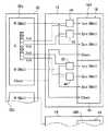
図1に、本発明の画像表示方法を利用する、本発明の画像表示装置の一例の概念図を示す。
図1に示される画像表示装置10(以下、表示装置10とする)は、基本的に、2台のLCD(液晶ディスプレイ)12および14、ならびに、両LCDに画像データを供給する画像供給部16を有して構成される。
【0027】
表示装置10において、LCD12およびLCD14は、共に、デジタル駆動できるモノクロLCDパネル18(以下、LCDパネル18とする)に画像表示する、モノクロの画像表示装置である。なお、特に図示はしないが、両LCDは、バックライトやLCDパネル18のドライバ等、LCDパネルを利用する表示装置が有する各種の部材を有しているのは、言うまでもない。
画像供給部16と、LCD12およびLCD14とは、前述のDVI(Digital Visual Interface)などのデジタルのインターフェイス(i/f)20によって接続される。
【0028】
LCDパネル18は、一例として、QXGA(2048×1536画素)のカラーのLCDパネルのフィルタを無色にしてモノクロ化したものである。従って、LCDパネル18は、前述のように、3つのサブピクセル(以下、第1ピクセル(1pix)、第2ピクセル、および第3ピクセルとする)を有し、3つのサブピクセルで1画素を表現する。
【0029】
図示例の表示装置10は、このようなLCDパネル18のサブピクセル構造を利用して、各サブピクセルを独立して8ビットで変調することにより、前述の例と同様、9.5ビット(766階調)の画像表示を行う。
また、表示装置10においては、前述の図3や図4に示される例と同様に、QGSXのLCDパネル18を1024×1536画素ずつの右画面18Rと左画面18Lに2分割して、画像表示を行う。
この点に関しては、後に詳述する。
【0030】
なお、本発明において、モノクロディスプレイは、図示例のようなLCDに限定はされず、複数要素で1画素を表現するサブピクセル構造を有するモノクロディスプレイであれば、CRT(Cathode Ray Tube)、DMD(Digital Micromrror Device)ディスプレイ、プラズマディスプレイ、有機EL(Electro Luminescence)ディスプレイ等、各種のモノクロディスプレイが利用可能である。
中でも、小型で薄く、かつ軽量であり、さらに、入手が容易である等の点で、LCDパネル、特に、図示例のようなカラーLCDをモノクロ化してなるモノクロLCDパネルは、好適に利用される。
【0031】
従って、LCDパネル18も、サブピクセルを有するものであれば、カラーLCDをモノクロ化したものに限定はされず、各種のものが利用可能である。
動作モードも、TN(Twisted Nematic) モード、STN(Super Twisted Nematic) モード、ECB(Electrically Controlled Birefringence) モード、IPS(In-Plane Swiching) モード、MVA(Multi-domain Vertical Alignement)モード等の全ての動作モードが利用可能であり、さらに、スイッチング素子やマトリクスにも限定はない。
【0032】
画像供給部16は、例えば、パーソナルコンピュータ(あるいは、その一部)等で構成されるものであり、基本的に、画像処理部22、階調数変換部24、サブピクセルデータ変換部26、転送データ変換部28、およびビデオカード30を有して構成される。
【0033】
図示例の表示装置10においては、FCRやX線診断装置等の画像データ供給源Rから、10ビットの画像データが供給される。
画像処理部22は、画像データ供給源Rから供給された画像データに、輝度補正、シャープネス補正(鮮鋭度補正)、階調変換等の所定の画像処理を施す部位である。なお、各画像処理は、公知の方法で行えばよい。
【0034】
前述のように、サブピクセルを有するディスプレイでは、サブピクセルを個々に変調することにより、高階調化を図ることができ、図示例のように、8ビットの階調数の画像表示が可能なサブピクセルを3つ有するものであれば、8ビット×3で9.5ビットに相当する766階調の階調表現が可能である。
【0035】
前述のように、図示例の表示装置10は、これを利用して9.5ビット相当の画像表示を行うものであり、画像処理部22で処理された10ビットの画像データは、階調数変換部24において、1画素に対応する9.5ビットの766階調(0〜765)の画像データに変換され、次いで、サブピクセルデータ変換部26において、1画素の各サブピクセルに対応する3つの8ビットの画像データに変換される。
【0036】
階調数変換部24における階調数の変換方法には、特に限定はなく、公知の方法によればよい。例えば、10ビットの画像データをx、9.5ビットの画像データをyとした際に、下記演算
y=(x/1023)×765
によって、10ビットの画像データxを9.5ビットの画像データyに変換するテーブルを作成しておき、これを用いて階調数を変換する方法が例示される。
【0037】
サブピクセルデータ変換部26は、階調数変換部24が変換した9.5ビットの画像データを、3等分し、余りを1ずつ、例えば第1ピクセルから割り振るようにして、第1ピクセル、第2ピクセルおよび第3ピクセルの各サブピクセルの8ビットの画像データとする。
具体的には、1画素の各サブピクセルの画像データを(第1ピクセル,第2ピクセル,第3ピクセル)で示すとして、サブピクセルデータ変換部26は、
9.5ビットの画像データ381であれば(127,127,127)、
同画像データ382であれば(128,127,127)、
同画像データ383であれば(128,128,127)、
同画像データ384であれば(128,128,128)のように、1画素の9.5ビットの画像データを、3つのサブブピクセルの8ビットの画像データに変換する。
【0038】
サブピクセルデータ変換部26で変換された各サブピクセルの8ビットの画像データは、次いで、転送データ変換部28において、LCD12および14に転送するための、転送用の画像データ(転送データ)に変換される。図示例においては、好ましい態様として、第1ピクセルおよび第2ピクセルの1ビットの転送データと、第3ピクセルの8ビットの転送データ(すなわち、第3ピクセルはそのまま)に変換される。
本発明においては、このように1画素を構成するサブピクセルと、その他のサブピクセルとで、異なる階調数の画像データとすることにより、転送する画像データ量を大幅に低減して、例えば後述するような、DVIによるデータ転送を用いて1台のビデオカードで2枚のQXGAのLCDパネル18に画像表示を行う、1カード2ヘッドのモノクロ画像の表示システムにおいて、サブピクセルを利用する9.5ビットの高階調画像の表示を可能にしている。
【0039】
前述のように、8ビットの3つのサブピクセルからなる1画素で、9.5ビットの画像データ381を表示する際には、各サブピクセルの画像データは(127,127,127)である。以下同様に、画像データ382は(128,127,127)、画像データ383は(128,128,127)で、画像データ384で全てのサブピクセルが同じの(128,128,128)となる。
これより明らかなように、サブピクセルを利用する高階調化では、サブピクセルの各画像データは、ある一つのサブピクセルの画像データに「0」か「1」を加算した画像データとなる。
【0040】
すなわち、サブピクセルを利用する高階調化では、1画素の画像データは、表示階調に対応する1つのサブピクセルの画像データ(基準データ)と、その他のサブピクセルの画像データと基準データとの差分を取った1ビット(「0」もしくは「1」)の差分データとで表現できる。また、基準データに、1ビットの差分データを加算すれば、基準データ以外のサブピクセルの画像データを、容易に復元することができる。
従って、この方法を利用することにより、データ量を大幅に低減でき、例えば、3つのサブピクセルを利用する9.5ビットの画像表示であれば、通常は、1画素で3×8=24ビットのデータ量が必要であったものを、8+1+1=10ビット相当の画像データ量に低減することができる。
【0041】
本発明は、これを利用するものであり、転送データ変換部28は、第3ピクセルを基準データとして、サブピクセルデータ変換部26から供給された8ビットの画像データをそのまま転送データとし、第1ピクセルおよび第2ピクセルは、基準データとの差分をとった1ビットのデータを転送データとする。
【0042】
例えば、9.5ビットの画像データ381であれば、サブピクセルデータ変換部26で変換された各サブピクセルの画像データは(127,127,127)であるので、転送データ変換部28は、第3ピクセルは8ビットの画像データ127を転送データとし、第1ピクセルおよび第2ピクセルは、差分を取った0を転送データとする。すなわち、転送データは(0,0,127)となる。
以下同様に、9.5ビットの画像データ382であれば、サブピクセルの画像データは(128,127,127)であるので、転送データは(1,0,127)となり、
同画像データ383であれば、サブピクセルの画像データは(128,128,127)であるので、転送データは(1,1,127)となり、
同画像データ384であれば、サブピクセルの画像データは(128,128,128)であるので、転送データは(0,0,128)となる。
【0043】
転送データ変換部28で変換された転送データ(1画素につき,8ビット、1ビット×2)は、ビデオカード30に送られ、i/f20を介して、LCD12およびLCD14に転送される。
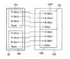
図2に、ビデオカード30と両LCDとのデータ転送を概念的に示す。
【0044】
前述のように、ビデオカード30は、DVIなどのデジタルのi/f20に対応するビデオカード(ディスプレイカード、グラフィックスカード、グラフィックスサブシステム)であり、第1リンク32aおよび第2リンク32bの2つの出力系統を有する。図示例においては、第1リンク32aは1台目のLCD12に、第2リンク32bは2台目のLCD14に、それぞれ接続される。
また、各リンクは、R画像データ、G画像データおよびB画像データに対応する3つのチャンネル(以下、Rチャンネル、GチャンネルおよびBチャンネルとする)と、クロック信号の出力とを有する。
さらに、LCD12とLCD14のLCDパネル18は、QXGA(2048×1536画素)のパネルであり、前述のように、1024×1536画素の右画面18Rおよび左画面18Lに分割されて、表示が行われる。
【0045】
なお、表示装置10においては、第1リンク32aと第2リンク32b、ならびに、LCD12とLCD14は、共に、同様の構成を有するので、図2においては、第1リンク32aとLCD12を具体的に示して、以下の説明を行う。
【0046】
図示例の表示装置10において、転送データ変換部28で変換された転送データのうち、LCD12による表示に対応する転送データは、ビデオカード30の第1リンク32aに、LCD14による表示に対応する転送データは、同第2リンク32bに、それぞれ供給される。
【0047】
前述のように、本例では、第3ピクセルを基準として、転送データを生成している。
図示例においては、第1リンク32a(第2リンク32b)に供給された転送データのうち、LCDパネル18の右画面18Rの第3ピクセルの転送データは、Rチャンネルに送られる。
また、LCDパネル18の左画面18Lの第3ピクセルの転送データは、Bチャンネルに送られる。
【0048】
全サブピクセルを同じ画像データで駆動する前述の図4に示される例では、使用されていなかったが、本例では、第1および第2ピクセルの転送データ(差分データ)の転送に、このGチャンネルを利用する。
図示例においては、右画面18Rの第1ピクセルの転送データは、Gチャンネルの3ビット目に、同第2ピクセルの転送データは、Gチャンネルの4ビット目に、それぞれ、送られる。他方、左画面18Lの第1ピクセルの転送データは、Gチャンネルの7ビット目に、同第2ピクセルの転送データは、Gチャンネルの8ビット目に、それぞれ、送られる。
【0049】
それぞれの第1リンク32aの各チャンネルに送られた転送データは、i/f20によって、LCD12に転送される。
図示例のLCD12は、右画面18Rに対応する加算部34および36と、左画面18Lに対応する加算部38および40を有する。なお、これらの加算部におけるデータの加算は、公知の方法で行えばよい。
【0050】
第1リンク32aのRチャンネルから転送された、右画面の第3ピクセルの転送データ(8ビット)は、右画面18Rの第3ピクセルの表示用の画像データ(表示データ)として、LCDパネル18(そのドライバ)に送られると共に、加算部34および36にも送られる。
【0051】
Gチャンネルの3ビット目に送られた右画面18Rの第1ピクセルの転送データ(1ビット)は、加算部34に送られる。この転送データは、加算部34において、第3ピクセルの転送データと加算されて、第1ピクセルの8ビットの画像データに復元される。例えば、元が9.5ビットの画像データ382であれば、各サブピクセルの画像データは(128,127,127)であり、前述のように、転送データは(1,0,127)であるので、加算部34において、第3ピクセルおよび第1ピクセルの転送データが加算「127+1」されて、元の第1ピクセルの8ビットの画像データ128に復元される。
復元された8ビットの画像データは、右画面18Rの第1ピクセルの表示データとして、LCDパネル18に送られる。
【0052】
さらに、Gチャンネルの4ビット目に送られた右画面18Rの第2ピクセルの転送データ(1ビット)は、加算部36に送られ、同様に第3ピクセルの転送データと加算されて、第2ピクセルの8ビットの画像データに復元される。例えば、元が同じく9.5ビットの画像データ382であれば、第3ピクセルの転送データは127で第2ピクセルの転送データは0であり、加算部36において両者が加算「127+0」されて、元の第2ピクセルの8ビットの画像データ127に復元される。
復元された8ビットの画像データは、右画面18Rの第3ピクセルの表示データとして、LCDパネル18に送られる。
【0053】
左画面18Lに対する表示データも、基本的に同様にLCDパネル18に供給される。
すなわち、Bチャンネルに送られた右画面18Lの第3ピクセルの転送データは、右画面18Lの第3ピクセルの表示データとしてLCDパネル18に送られると共に、加算部38および40にも送られる。
Gチャンネルの7ビット目に送られた左画面18Lの第1ピクセルの転送データは、加算部38に送られ、ここで、前記第3ピクセルの転送データと加算されて、元の第1ピクセルの8ビットの表示データに復元され、さらに、Gチャンネルの8ビット目に送られた左画面18Lの第2ピクセルの転送データは、加算部40に送られ、ここで、第3ピクセルの転送データと加算されて、元の第2ピクセルの8ビットの表示データに復元され、それぞれ、LCDパネル18に送られる。
【0054】
表示データを送られたLCDパネル18は、右画面18Rおよび左画面18Lのそれぞれで、供給された8ビットの表示データに応じて各画素のサブピクセルを変調し、QXGAのLCDパネル18において、9.5ビットのモノクロの画像が表示される。
また、図示例においては、ビデオカード30の第2リンク32bからも、全く同様にして、もう一台のLCD14に転送データが転送され、LCDパネル18による9.5ビットのモノクロ画像の表示が行われる。
【0055】
すなわち、本発明の表示装置10では、差分データを利用して転送データの量を大幅に低減すると共に、通常の全サブピクセルを同じ画像データで駆動するモノクロ画像の表示では利用しない、ビデオカードのリンクの空きチャンネルを利用することにより、DVIによる画像データ転送であっても、1つのビデオカード30で、2枚のQXGAのLCDパネル18に9.5ビット(766階調)の画像を表示することができる。すなわち、安価な1カード2ヘッドのシステムで、高精細なQXGAのモノクロLCDによる9.5ビットの高階調表示を実現することができる。
特に、前述の医療用途では、高精細でかつ高階調な画像が要求されると共に、2台のディスプレイを並べて、複数の画像を縦表示する場合が多いので、このような1カード2ヘッドのシステムは、有用である。
【0056】
以下、表示装置10の作用を説明する。
表示装置10において、画像データ供給源Rから供給された10ビットの画像データは、まず、画像処理部22で階調変換等の所定の画像処理を施された後、階調数変換部24において、9.5ビットの画像データに変換される。
この画像データは、次いで、サブピクセルデータ変換部26において、1画素の各サブピクセルに対応する8ビット×3の画像データに変換され、転送データ変換部28に送られる。
転送データ変換部28では、第3ピクセルの画像データを基準として、残りのサブピクセルの画像データとの差分データを算出し、各サブピクセルに対応する1ビット×2(第1および第2ピクセル)および8ビット(第3ピクセル)の転送データとする。
【0057】
転送データは、ビデオカード30に送られる。
前述のように、ビデオカード30においては、LCD12に対応する転送データは第1リンク32aの各チャンネルに、LCD14に対応する転送データは第2リンク32bの各チャンネルに、それぞれ送られる。
また、LCDパネル18の右画面18Rの第3ピクセルの転送データはRチャンネルに、第1ピクセルの転送データはGチャンネルの3ビット目に、第2ピクセルの画像データはGチャンネルの3ビット目に、それぞれ送られる。他方、LCDパネル18の左画面18Lの第3ピクセルの転送データはBチャンネルに、第1ピクセルの転送データはGチャンネルの7ビット目に、第2ピクセルの画像データはGチャンネルの8ビット目に、それぞれ送られる。
【0058】
各チャンネルに送られた転送データは、DVI等のデジタルのi/f20によってLCD12およびLCD14に送られる。
前述のように、第3ピクセルの転送データ(8ビット)は、表示データとしてLCDパネル18(ドライバ)に送られ、第1ピクセルの転送データ(1ビット)は加算部34および38において第3ピクセルの転送データと加算されて元の8ビットの画像データに復元され、表示データとしてLCDパネル18に送られ、さらに、第2ピクセルの転送データ(1ビット)は加算部36および40において第3ピクセルの転送データと加算されて元の8ビットの画像データに復元され、表示データとしてLCDパネル18に送られる。
【0059】
LCDパネル18では、送られた表示データに応じて各画素のサブピクセルを駆動(変調)して、2台のLCD12および14(2枚のLCDパネル18)に、9.5ビットの階調を有する画像が表示される。
【0060】
以上、本発明の画像表示方法および画像表示装置について詳細に説明したが、本発明は上記実施例に限定はされず、本発明の要旨を逸脱しない範囲において、各種の改良や変更を行ってもよいのは、もちろんである。
【0061】
例えば、図示例は、1枚のビデオカードから2台のLCDに画像データを転送して、1カード2ヘッドのシステムを実現しているが、本発明はこれに限定はされず、1台で2枚のモノクロLCDパネルを有するLCDに画像データを転送して、1カード2ヘッドのシステムを実現してもよい。
【0062】
また、モノクロLCDパネル(モノクロディスプレイ)の画素数も、図示例のQXGAに限定はされず、QSXGA(2560×2048画素)、QUXGA(3200×2400画素)、QUXGA−W(3840×2400画素)等のモノクロLCDパネルに画像を表示する場合にも、本発明は利用可能であるのはもちろんである。あるいは、これより低画素数のUXGA(1600×1200画素)にモノクロLCDパネルを用いる場合等で、i/fの転送レートが不十分な場合にも、本発明は好適に利用可能である。
【0063】
【発明の効果】
以上、詳細に説明したように、本発明によれば、デジタルのi/fおよびサブピクセル構造を有するモノクロLCDパネルに画像を表示する際に、i/fの転送レートが不十分である場合にも適正な画像データの転送を行うことができ、例えば、DVIで画像データを転送してQXGAのモノクロLCDパネルに画像を表示する1カード2ヘッドのシステムにおいて、サブピクセルを利用した9.5ビットの高階調画像を表示することを可能にできる。
【図面の簡単な説明】
【図1】 本発明の画像表示方法を利用する画像表示装置の一例のブロック図である。
【図2】 図1に示される画像表示装置における、ビデオカードとLCDとのデータ転送を説明する概念図である。
【図3】 従来のカラー画像表示装置における、ビデオカードとLCDとのデータ転送の一例を説明する概念図である。
【図4】 従来のモノクロ画像表示装置における、ビデオカードとLCDとのデータ転送の一例を説明する概念図である。
【符号の説明】
10 (画像)表示装置
12,14,100,110,112 LCD
16 データ転送部
18,114 (モノクロ)LCDパネル
18R,102R,114R 右画面
18L,102L,114L 左画面
20 i/f(インターフェース)
22 画像処理部
24 階調数変換部
26 サブピクセルデータ変換部
28 転送データ変換部
30 ビデオカード
32a 第1リンク
32b 第2リンク
34,36,38,40 加算部
116R,116L 展開手段[0001]
BACKGROUND OF THE INVENTION
The present invention belongs to the technical field of image display using a monochrome display, and more specifically, an image that enables high-gradation pixel display using a subpixel structure to be performed on a plurality of monochrome displays with a single video card. The present invention relates to a display method and an image display device.
[0002]
[Prior art]
Various medical images taken (measured) by medical diagnostic apparatuses such as an ultrasonic diagnostic apparatus, CT diagnostic apparatus, MRI diagnostic apparatus, X-ray diagnostic apparatus, and FCR (Fuji Computed Radiography) After the image processing is performed, the image is usually reproduced as a visible image on a film-like recording material by a printer such as a laser printer or a thermal printer and output as a hard copy.
A film on which a medical image is reproduced is observed in a medical site using a light box called a shark caster and is used for various diagnoses.
[0003]
In recent years, a medical image taken by a medical diagnostic apparatus is reproduced as a soft copy on a display and diagnosed.
Currently, CRT (Cathode Ray Tube) is the mainstream display for medical diagnostic equipment, but it has many advantages such as being easy to miniaturize, thin and lightweight, In recent years, adoption of a liquid crystal display (LCD) as a display of a medical diagnostic apparatus is also being studied.
[0004]
As you know, on the LCDUsed The LCD panel can be digitally driven. In recent years, an interface (i / f) that can transfer a digital signal such as DVI (Digital Visual Interface) to a display has been widely used, and an LCD panel is used to achieve high image quality without deterioration due to digital-analog signal conversion. An image is displayed.
Also, in DVI which is the most widely used digital image i / f, a serial data transfer method called TMDS (transition minimized differential signaling) is adopted.
[0005]
In such a system using digital image data transfer by DVI, when displaying 8-bit color images of R (red), G (green) and B (blue), UXGA (1600 × 1200) Pixels) to HDTV (1920 × 1080 pixels), and when displaying an image on a higher pixel display such as a QXGA (2048 × 1536 pixels) color LCD panel, the image data is transferred. Is not in time.
For this reason, when image data is transferred to a QXGA digital color LCD panel using DVI and an image is displayed, the LCD panel is divided into two to display the image. An example is conceptually shown in FIG.
[0006]
In the system shown in FIG. 3, the
The QXGA
The
[0007]
Under such a configuration, the
As described above, the number of pixels of the
[0008]
Here, a video card inserted into a PCI (peripheral component interconnect) bus that is normally used in a PC or the like can mount only two DVI connectors due to the board, connector size, and the like.
Therefore, at present, when transferring image data to a QXGA color LCD panel by DVI and displaying an image, one video card (one card) is required for one LCD panel (one head). Yes (1
[0009]
By the way, among the medical images as described above, for example, a diagnostic image taken by an FCR or an X-ray diagnostic apparatus is usually displayed as a monochrome image.
In addition, a monochrome LCD panel that has been converted to black and white by removing the color filter of the color LCD panel has been put into practical use.
[0010]
Here, since the color LCD panel has R, G, and B subpixels for one pixel, the monochrome LCD panel in which the color LCD panel is monochromeized has three subpixels for one pixel. When an image is displayed on such a monochrome LCD panel, usually, all subpixels of one pixel are driven (modulated) with the same image data.
In the monochrome LCD panel, the practical application of a system with one card and two heads for displaying images on two QXGA panels with one video card using image data transfer by DVI is being considered. Yes. The conceptual diagram of the example is shown in FIG.
[0011]
As described above, the
In FIG. 4, since the second
[0012]
As described above, the
Further, the
[0013]
As described above, the
Therefore, an image can be displayed on the
[0014]
In the illustrated example, in the
In this example, the channel corresponding to the G image data is not used.
[0015]
Upon receiving the image data, the expansion means 116R expands (duplicates) the image data, generates three pieces of the same 8-bit image data, and the first pixel and the second pixel of the corresponding pixels on the
[0016]
That is, according to this method, an image can be displayed on one QXGA
Therefore, if both of the two links of the
[0017]
As is well known, in medical applications, diagnosis is often performed while displaying a large number of images such as captured images of different parts of the same patient and past and current captured images. For this reason, there are many applications in which images are displayed vertically (portrait) and two monochrome LCDs (monochrome LCD panels) are used side by side.
In such an application, the one-card / two-head system is advantageous in terms of cost since only one video card is required.
[0018]
[Problems to be solved by the invention]
By the way, in a monochrome display having sub-pixels such as this monochrome LCD panel, each sub-pixel is disclosed as disclosed in Japanese Patent Application Laid-Open Nos. 11-31971 and 11-352594 related to the present applicant. It is possible to increase the gradation by individually modulating the.
For example, in the monochrome LCD panel in which the color filter of the color LCD is monochromatic, if each subpixel can be driven with 8 bits (256 gradations), one subtotal of three subpixels is used. It is possible to perform gradation expression equivalent to 5 bits (766 gradations).
In medical applications, this method is very advantageous because an image with higher gradation and higher image quality is required for accurate diagnosis.
[0019]
Here, when the gradation is increased by using this method, for example, when 9.5 bits are expressed by the monochrome LCD panel having the three subpixels, the three subpixels are individually independent. Therefore, it is necessary to drive with 8 bits.
Therefore, in this case, when data is transferred using DVI and an image is displayed on a QXGA monochrome LCD panel, the image data is transferred in the same manner as in the case of the
[0020]
In other words, in this way, when increasing the gradation using subpixels, a system of one card and two heads is realized as shown in FIG. 4 in which three subpixels are driven with the same image data. Can not do it. For this reason, when an image is displayed on two monochrome LCD panels, two cards and two heads must be used, resulting in an increase in cost.
[0021]
An object of the present invention is to solve the above-described problems of the prior art. When an image is displayed on a monochrome LCD panel having a digital interface and a sub-pixel structure, the i / f of the number of pixels of the panel is set. Even when the transfer rate is insufficient, it is possible to transfer image data by reducing the data transfer amount and display images. For example, image data can be transferred from one video card by DVI. Thus, in a one-card two-head system that displays images on two 8-bit QXGA monochrome LCD panels, it is possible to display a 9.5-bit high gradation image using subpixels. An object is to provide a display method and an image display device.
[0022]
[Means for Solving the Problems]
In order to achieve the above object, the image display method of the present invention provides input image data when displaying an image on a monochrome display having a digital interface and a subpixel structure having a plurality of subpixels per pixel.Is divided into a plurality of sub-pixels of each pixel of the monochrome display to create a plurality of conversion data corresponding to each of the plurality of sub-pixels and having the same bit number as the image display bit number in the monochrome display, Among a plurality of subpixels of each pixel of the monochrome display, for one subpixel,Consists of the converted data corresponding to this sub-pixel Reference data for other subpixelsConsists of the difference between the converted data corresponding to each sub-pixel and the reference data 1-bit transfer image data is generated and transferred to the monochrome display. In the monochrome display, 1-bit transfer image data for the other subpixels is added to reference data for the one subpixel. To generate display image data having the same number of bits as the reference data for the other sub-pixels, and using the reference data and the display image data, a gradation image corresponding to the number of bits of the input image data A method for displaying an image is provided.
[0023]
The image display apparatus according to the present invention further includes a digital interface and a monochrome display having a subpixel structure including a plurality of subpixels per pixel, and an image data transfer unit that transfers digital image data to the monochrome display. And the image data transfer unit has input image dataIs divided into a plurality of sub-pixels of each pixel of the monochrome display to create a plurality of conversion data corresponding to each of the plurality of sub-pixels and having the same bit number as the image display bit number in the monochrome display, Among a plurality of subpixels of each pixel of the monochrome display, for one subpixel,Consists of the converted data corresponding to this sub-pixel Reference data for other subpixelsConsists of the difference between the converted data corresponding to each sub-pixel and the reference data Means for generating 1-bit transfer image data, and transferring the transfer image data and reference data to the monochrome display; and the monochrome display further includes the other as reference data for the one sub-pixel. Means for generating display image data having the same number of bits as the reference data for the other sub-pixels by adding 1-bit transfer image data to the sub-pixels of the sub-pixels. Provided is an image display device characterized by performing gradation-based image display corresponding to the number of bits of the input image data using reference data.
[0024]
Furthermore, in the present invention,3 sub-pixels per pixel On the monochrome displayView image It is preferable to display the image on the monochrome display.bit The number is preferably 8 bits, the monochrome display is preferably a liquid crystal display, the number of pixels of the monochrome display is preferably 2048 × 1536 pixels (QXGA) or more, and one video It is preferable to connect a plurality of monochrome displays to the card, and it is preferable to display an image vertically on the monochrome display.
[0025]
DETAILED DESCRIPTION OF THE INVENTION
Hereinafter, the image display method and the image display apparatus of the present invention will be described in detail on the basis of preferred embodiments shown in the accompanying drawings.
[0026]
FIG. 1 shows a conceptual diagram of an example of an image display apparatus of the present invention that uses the image display method of the present invention.
An image display device 10 (hereinafter referred to as a display device 10) shown in FIG. 1 basically includes two LCDs (liquid crystal displays) 12 and 14, and an
[0027]
In the
The
[0028]
As an example, the
[0029]
The
In the
This will be described in detail later.
[0030]
In the present invention, the monochrome display is not limited to the LCD as shown in the illustrated example, and any CRT (Cathode Ray Tube), DMD (CRT) can be used as long as it is a monochrome display having a sub-pixel structure that expresses one pixel by a plurality of elements. Various monochrome displays such as a digital micro device (plasma display), a plasma display, and an organic EL (Electro Luminescence) display can be used.
Among them, an LCD panel, in particular, a monochrome LCD panel obtained by converting a color LCD as shown in the figure into a monochrome image is preferably used because it is small, thin, lightweight, and easily available. .
[0031]
Therefore, as long as the
All operation modes such as TN (Twisted Nematic) mode, STN (Super Twisted Nematic) mode, ECB (Electrically Controlled Birefringence) mode, IPS (In-Plane Swiching) mode, MVA (Multi-domain Vertical Alignement) mode, etc. The mode can be used, and there is no limitation on the switching element and the matrix.
[0032]
The
[0033]
In the
[0034]
As described above, in a display having sub-pixels, it is possible to increase the gradation by individually modulating the sub-pixels, and the sub-pixels capable of displaying an image with a gradation number of 8 bits as in the illustrated example. If there are three pixels, it is possible to express 766 gradations corresponding to 9.5 bits by 8 bits × 3.
[0035]
As described above, the
[0036]
The gradation number conversion method in the gradation
y = (x / 1023) × 765
Thus, a method of creating a table for converting 10-bit image data x into 9.5-bit image data y and converting the number of gradations using this table is exemplified.
[0037]
The sub-pixel
Specifically, assuming that the image data of each sub-pixel of one pixel is indicated by (first pixel, second pixel, third pixel), the sub-pixel
If the image data 381 is 9.5 bits (127, 127, 127),
If the image data 382 (128, 127, 127),
If the same image data 383 (128, 128, 127),
In the case of the image data 384, as in (128, 128, 128), 9.5-bit image data of one pixel is converted into 8-bit image data of three sub-pixels.
[0038]
The 8-bit image data of each subpixel converted by the subpixel
In the present invention, the amount of image data to be transferred is greatly reduced by making the image data having different gradation numbers in the sub-pixels constituting one pixel and the other sub-pixels as described above. 8. Sub-pixels are used in a one-card, two-head monochrome image display system that performs image display on two
[0039]
As described above, when displaying 9.5-bit image data 381 with one pixel composed of three 8-bit sub-pixels, the image data of each sub-pixel is (127, 127, 127). Similarly, the image data 382 is (128, 127, 127), the image data 383 is (128, 128, 127), and all subpixels in the image data 384 are the same (128, 128, 128).
As is clear from this, in the case of high gradation using subpixels, each subpixel image data is image data obtained by adding “0” or “1” to the image data of one subpixel.
[0040]
That is, in the case of high gradation using subpixels, the image data of one pixel includes image data (reference data) of one subpixel corresponding to the display gradation, and image data and reference data of other subpixels. The difference can be expressed by 1-bit difference data ("0" or "1"). Further, if 1-bit difference data is added to the reference data, the image data of subpixels other than the reference data can be easily restored.
Therefore, by using this method, the amount of data can be significantly reduced. For example, in the case of a 9.5-bit image display using three subpixels, one pixel usually has 3 × 8 = 24 bits. Can be reduced to an image data amount equivalent to 8 + 1 + 1 = 10 bits.
[0041]
The present invention utilizes this, and the transfer
[0042]
For example, in the case of 9.5-bit image data 381, the image data of each subpixel converted by the subpixel
Similarly, in the case of 9.5-bit image data 382, since the sub-pixel image data is (128, 127, 127), the transfer data is (1, 0, 127).
In the case of the image data 383, since the image data of the sub-pixel is (128, 128, 127), the transfer data is (1, 1, 127).
In the case of the image data 384, since the sub-pixel image data is (128, 128, 128), the transfer data is (0, 0, 128).
[0043]
The transfer data (8 bits per pixel, 1 bit × 2) converted by the transfer
FIG. 2 conceptually shows data transfer between the
[0044]
As described above, the
Each link has three channels (hereinafter referred to as R channel, G channel, and B channel) corresponding to R image data, G image data, and B image data, and an output of a clock signal.
Further, the
[0045]
In the
[0046]
In the
[0047]
As described above, in this example, the transfer data is generated based on the third pixel.
In the illustrated example, among the transfer data supplied to the
The transfer data of the third pixel on the
[0048]
In the example shown in FIG. 4 in which all the sub-pixels are driven with the same image data, this is not used. In this example, the transfer data (difference data) of the first and second pixels is used for transferring the G data. Use channels.
In the illustrated example, the transfer data of the first pixel of the
[0049]
The transfer data sent to each channel of each
The
[0050]
The transfer data (8 bits) of the third pixel of the right screen transferred from the R channel of the
[0051]
The transfer data (1 bit) of the first pixel of the
The restored 8-bit image data is sent to the
[0052]
Further, the transfer data (1 bit) of the second pixel of the
The restored 8-bit image data is sent to the
[0053]
Display data for the
That is, the transfer data of the third pixel of the
The transfer data of the first pixel of the
[0054]
The
In the illustrated example, the transfer data is transferred from the
[0055]
That is, in the
In particular, in the above-described medical use, a high-definition and high-gradation image is required, and there are many cases where two displays are arranged side by side to display a plurality of images vertically. Is useful.
[0056]
Hereinafter, the operation of the
In the
This image data is then converted into 8-bit × 3 image data corresponding to each sub-pixel of one pixel by the sub-pixel
The transfer
[0057]
The transfer data is sent to the
As described above, in the
Also, the transfer data of the third pixel on the
[0058]
The transfer data sent to each channel is sent to the
As described above, the transfer data (8 bits) of the third pixel is sent to the LCD panel 18 (driver) as display data, and the transfer data (1 bit) of the first pixel is sent to the third pixel in the
[0059]
The
[0060]
Although the image display method and the image display apparatus of the present invention have been described in detail above, the present invention is not limited to the above-described embodiments, and various improvements and modifications can be made without departing from the gist of the present invention. Of course it is good.
[0061]
For example, in the example shown in the figure, image data is transferred from one video card to two LCDs to realize a system with one card and two heads. However, the present invention is not limited to this, and one unit is used. A system with one card and two heads may be realized by transferring image data to an LCD having two monochrome LCD panels.
[0062]
In addition, the number of pixels of the monochrome LCD panel (monochrome display) is not limited to the QXGA in the illustrated example. QSXGA (2560 × 2048 pixels), QUXGA (3200 × 2400 pixels), QUXGA-W (3840 × 2400 pixels) Of course, the present invention can also be used when displaying an image on a monochrome LCD panel. Alternatively, when the monochrome LCD panel is used for UXGA (1600 × 1200 pixels) having a lower number of pixels than this, and the i / f transfer rate is insufficient, the present invention can be suitably used.
[0063]
【The invention's effect】
As described above in detail, according to the present invention, when an image is displayed on a monochrome LCD panel having a digital i / f and subpixel structure, the i / f transfer rate is insufficient. Can transfer image data properly. For example, in a 1-card 2-head system that transfers image data using DVI and displays an image on a QXGA monochrome LCD panel, 9.5 bits using subpixels. It is possible to display a high gradation image.
[Brief description of the drawings]
FIG. 1 is a block diagram of an example of an image display device that uses an image display method of the present invention.
FIG. 2 is a conceptual diagram illustrating data transfer between a video card and an LCD in the image display apparatus shown in FIG.
FIG. 3 is a conceptual diagram illustrating an example of data transfer between a video card and an LCD in a conventional color image display device.
FIG. 4 is a conceptual diagram illustrating an example of data transfer between a video card and an LCD in a conventional monochrome image display device.
[Explanation of symbols]
10 (Image) display device
12, 14, 100, 110, 112 LCD
16 Data transfer unit
18,114 (monochrome) LCD panel
18R, 102R, 114R Right screen
18L, 102L, 114L Left screen
20 i / f (interface)
22 Image processing unit
24 gradation number conversion part
26 Subpixel data converter
28 Transfer data converter
30 video card
32a 1st link
32b Second link
34, 36, 38, 40 Adder
116R, 116L deployment means
Claims (8)
Translated fromJapanese入力画像データを前記モノクロディスプレイの各画素の複数のサブピクセルに分割することにより、これら複数のサブピクセルにそれぞれ対応すると共に前記モノクロディスプレイにおける画像表示のビット数と同じビット数の複数の変換データを作成し、
前記モノクロディスプレイの各画素の複数のサブピクセルのうち、1つのサブピクセルに対してはこのサブピクセルに対応する前記変換データからなる基準データを、その他のサブピクセルに対してはそれぞれのサブピクセルに対応する前記変換データと前記基準データとの差分からなる1ビットの転送用画像データをそれぞれ生成して前記モノクロディスプレイに転送し、
前記モノクロディスプレイにおいて、前記1つのサブピクセルに対する基準データに前記その他のサブピクセルに対する1ビットの転送用画像データを加算することにより前記その他のサブピクセルに対して前記基準データと同じビット数の表示用画像データを生成し、前記基準データ及び前記表示用画像データを用いて前記入力画像データのビット数に対応する諧調の画像を表示する
ことを特徴とする画像表示方法。When displaying an image on a monochrome display having a digital interface and a sub-pixel structure with a plurality of sub-pixels per pixel,
By dividing the input image datainto a plurality of sub-pixels of each pixel of the monochrome display, a plurality of conversion data corresponding to each of the plurality of sub-pixels and having the same bit number as the image display bit number in the monochrome display are obtained. make,
Among a plurality of subpixels of each pixel of the monochrome display, for onesubpixel, the reference datacomposed of the conversion data corresponding to this subpixel is used, and for the other subpixels, therespective subpixels are used. 1-bit transfer image dataconsisting of the difference between the corresponding conversion data and the reference data is generated and transferred to the monochrome display,
In the monochrome display, by adding 1-bit transfer image data for the other sub-pixels to the reference data for the one sub-pixel, for the display of the same number of bits as the reference data for the other sub-pixels An image display method comprising: generating image data and displaying a gradation image corresponding to the number of bits of the input image data using the reference data and the display image data.
かつ、前記画像データ転送部は、入力画像データを前記モノクロディスプレイの各画素の複数のサブピクセルに分割することにより、これら複数のサブピクセルにそれぞれ対応すると共に前記モノクロディスプレイにおける画像表示のビット数と同じビット数の複数の変換データを作成し、前記モノクロディスプレイの各画素の複数のサブピクセルのうち、1つのサブピクセルに対してはこのサブピクセルに対応する前記変換データからなる基準データを、その他のサブピクセルに対してはそれぞれのサブピクセルに対応する前記変換データと前記基準データとの差分からなる1ビットの転送用画像データをそれぞれ生成する手段を有し、この転送用画像データと基準データを前記モノクロディスプレイに転送し、
さらに、前記モノクロディスプレイは、前記1つのサブピクセルに対する基準データに前記その他のサブピクセルに対する1ビットの転送用画像データを加算することにより前記その他のサブピクセルに対して前記基準データと同じビット数の表示用画像データを生成する手段を有し、この表示用画像データと基準データを用いて前記入力画像データのビット数に対応する諧調の画像表示を行う
ことを特徴とする画像表示装置。A monochrome interface having a digital interface and a sub-pixel structure having a plurality of sub-pixels per pixel, and an image data transfer unit for transferring digital image data to the monochrome display;
The image data transfer unitdivides the input image datainto a plurality of subpixels of each pixel of the monochrome display, thereby corresponding to each of the plurality of subpixels and the number of bits for image display on the monochrome display. A plurality of conversion data having the same number of bits is created, and among the plurality of sub-pixels of each pixel of the monochrome display, for one sub-pixel, reference datacomposed of the conversion data corresponding to this sub-pixel, and the otherEach sub-pixel has means for generating 1-bit transfer image dataconsisting of a difference between the conversion data corresponding to each sub-pixel and the reference data, and the transfer image data and the reference data To the monochrome display,
Further, the monochrome display adds the 1-bit transfer image data for the other subpixels to the reference data for the one subpixel, so that the other subpixels have the same number of bits as the reference data. An image display device comprising means for generating display image data, and performing gradation image display corresponding to the number of bits of the input image data using the display image data and reference data.
Priority Applications (3)
| Application Number | Priority Date | Filing Date | Title |
|---|---|---|---|
| JP2000356257AJP4320117B2 (en) | 2000-11-22 | 2000-11-22 | Image display method and image display apparatus |
| EP01127772AEP1209654B1 (en) | 2000-11-22 | 2001-11-21 | Image display method and image display apparatus |
| US09/989,375US6888523B2 (en) | 2000-11-22 | 2001-11-21 | Image display method and image display apparatus |
Applications Claiming Priority (1)
| Application Number | Priority Date | Filing Date | Title |
|---|---|---|---|
| JP2000356257AJP4320117B2 (en) | 2000-11-22 | 2000-11-22 | Image display method and image display apparatus |
Publications (3)
| Publication Number | Publication Date |
|---|---|
| JP2002162939A JP2002162939A (en) | 2002-06-07 |
| JP2002162939A5 JP2002162939A5 (en) | 2005-11-04 |
| JP4320117B2true JP4320117B2 (en) | 2009-08-26 |
Family
ID=18828541
Family Applications (1)
| Application Number | Title | Priority Date | Filing Date |
|---|---|---|---|
| JP2000356257AExpired - Fee RelatedJP4320117B2 (en) | 2000-11-22 | 2000-11-22 | Image display method and image display apparatus |
Country Status (3)
| Country | Link |
|---|---|
| US (1) | US6888523B2 (en) |
| EP (1) | EP1209654B1 (en) |
| JP (1) | JP4320117B2 (en) |
Families Citing this family (12)
| Publication number | Priority date | Publication date | Assignee | Title |
|---|---|---|---|---|
| TW540022B (en)* | 2001-03-27 | 2003-07-01 | Koninkl Philips Electronics Nv | Display device and method of displaying an image |
| US20030142240A1 (en)* | 2002-01-29 | 2003-07-31 | Koninklijke Philips Electronics N.V. | Device and method for interfacing digital video processing devices |
| JP3796499B2 (en)* | 2002-11-06 | 2006-07-12 | キヤノン株式会社 | Color display element, color display element driving method, and color display device |
| EP1439455A1 (en)* | 2003-01-17 | 2004-07-21 | Harman/Becker Automotive Systems GmbH | Image display system for displaying different images on separate display devices |
| US7840714B2 (en)* | 2003-12-24 | 2010-11-23 | Intel Corporation | Mapping SDVO functions from PCI express interface |
| DE102006019545B4 (en)* | 2006-04-27 | 2008-02-28 | Dräger Medical AG & Co. KG | Interface unit, apparatus with such an interface unit and method for generating an image signal containing color image data for controlling a color monitor |
| US8018476B2 (en)* | 2006-08-28 | 2011-09-13 | Samsung Electronics Co., Ltd. | Subpixel layouts for high brightness displays and systems |
| TW200951731A (en)* | 2008-06-02 | 2009-12-16 | First Int Computer Inc | Changeable CPU module apparatus for a computer |
| US8803857B2 (en)* | 2011-02-10 | 2014-08-12 | Ronald S. Cok | Chiplet display device with serial control |
| JP2011235107A (en)* | 2011-05-27 | 2011-11-24 | Totoku Electric Co Ltd | Medical image display device and medical image display program |
| WO2013150705A1 (en)* | 2012-04-03 | 2013-10-10 | パナソニック株式会社 | Video data transmission device and reception device |
| FR3079991B1 (en)* | 2018-04-09 | 2020-04-03 | Commissariat A L'energie Atomique Et Aux Energies Alternatives | METHOD FOR TRANSMITTING A MONOCHROME DIGITAL IMAGE VIA A TRANSMISSION INTERFACE HAVING A PLURALITY OF TRANSMISSION CHANNELS |
Family Cites Families (18)
| Publication number | Priority date | Publication date | Assignee | Title |
|---|---|---|---|---|
| US4908780A (en)* | 1988-10-14 | 1990-03-13 | Sun Microsystems, Inc. | Anti-aliasing raster operations utilizing sub-pixel crossing information to control pixel shading |
| JPH06318060A (en)* | 1991-07-31 | 1994-11-15 | Toshiba Corp | Display controller |
| US5347620A (en)* | 1991-09-05 | 1994-09-13 | Zimmer Mark A | System and method for digital rendering of images and printed articulation |
| EP0884914A1 (en)* | 1993-02-03 | 1998-12-16 | Nitor | Methods and apparatus for image projection |
| KR100259783B1 (en)* | 1994-03-11 | 2000-06-15 | 미다라이 후지오 | Display pixel balancing for multiple color individual level displays |
| US5440339A (en)* | 1994-04-13 | 1995-08-08 | U.S. Philips Corporation | System and method for testing intensity response of a medical monochrome video monitor |
| EP0762370A3 (en)* | 1995-08-02 | 1998-01-07 | Canon Kabushiki Kaisha | Driving method for display apparatus including an optical modulation device |
| US6329963B1 (en)* | 1996-06-05 | 2001-12-11 | Cyberlogic, Inc. | Three-dimensional display system: apparatus and method |
| US6133894A (en)* | 1996-12-17 | 2000-10-17 | Canon Kabushiki Kaisha | Driving method for optical apparatus |
| US6104446A (en)* | 1996-12-18 | 2000-08-15 | Blankenbecler; Richard | Color separation optical plate for use with LCD panels |
| JP3634138B2 (en)* | 1998-02-23 | 2005-03-30 | 株式会社 日立ディスプレイズ | Liquid crystal display |
| JPH11352954A (en)* | 1998-04-10 | 1999-12-24 | Fuji Photo Film Co Ltd | Monochromic image display device |
| JPH11311971A (en) | 1998-04-30 | 1999-11-09 | Fuji Photo Film Co Ltd | Monochromatic image display device |
| JP4016493B2 (en)* | 1998-08-05 | 2007-12-05 | 三菱電機株式会社 | Display device and multi-gradation circuit thereof |
| US6564269B1 (en)* | 1998-09-10 | 2003-05-13 | Silicon Image, Inc. | Bi-directional data transfer using the video blanking period in a digital data stream |
| DE69936368T2 (en)* | 1998-09-22 | 2007-10-31 | Matsushita Electric Industrial Co., Ltd., Kadoma | Improved display method for grayscale images |
| US6342896B1 (en)* | 1999-03-19 | 2002-01-29 | Microsoft Corporation | Methods and apparatus for efficiently implementing and modifying foreground and background color selections |
| US6570584B1 (en)* | 2000-05-15 | 2003-05-27 | Eastman Kodak Company | Broad color gamut display |
- 2000
- 2000-11-22JPJP2000356257Apatent/JP4320117B2/ennot_activeExpired - Fee Related
- 2001
- 2001-11-21EPEP01127772Apatent/EP1209654B1/ennot_activeExpired - Lifetime
- 2001-11-21USUS09/989,375patent/US6888523B2/ennot_activeExpired - Fee Related
Also Published As
| Publication number | Publication date |
|---|---|
| EP1209654A2 (en) | 2002-05-29 |
| US6888523B2 (en) | 2005-05-03 |
| US20020084962A1 (en) | 2002-07-04 |
| JP2002162939A (en) | 2002-06-07 |
| EP1209654B1 (en) | 2012-04-04 |
| EP1209654A3 (en) | 2007-04-25 |
Similar Documents
| Publication | Publication Date | Title |
|---|---|---|
| JP5176194B2 (en) | Liquid crystal display device and image display system | |
| KR101095635B1 (en) | System and method for improving sub-pixel rendering of imaging data in non-striped display systems | |
| US6961040B2 (en) | Two-dimensional monochrome bit face display | |
| JP4320117B2 (en) | Image display method and image display apparatus | |
| JP3969899B2 (en) | Image display method and image display apparatus used therefor | |
| US6738054B1 (en) | Method and apparatus for image display | |
| US8982167B2 (en) | Sub-pixel rendering of a multiprimary image | |
| JPWO2011083606A1 (en) | Display device and driving method of display device | |
| JP4484784B2 (en) | Color sequential display method | |
| JPH1010517A (en) | Image display device | |
| US8373809B2 (en) | Display apparatus having an input gradation set to have a relationship along a gamma curve | |
| US6714208B1 (en) | Method of displaying monochromatic image on color monitor and image display apparatus for implementing the method | |
| US20080007574A1 (en) | Image display method | |
| JP2004258198A (en) | Image display device | |
| CN100565653C (en) | Image data processing system, display device, driving image-data generating method | |
| JP2002108317A (en) | Picture display method and picture display device | |
| Albani et al. | HDR medical display based on dual layer LCD | |
| JP2003284693A (en) | Medical image system | |
| JP2004198792A (en) | Display device and display method | |
| JP4141756B2 (en) | Monochrome liquid crystal image display device and interpretation report creation device using the same | |
| JP2002108265A (en) | Method and device for displaying picture | |
| JP2003295851A (en) | Image display device | |
| JP2000298460A (en) | Picture display method and picture display device | |
| JP2004170576A (en) | Flat panel display and display method using the same | |
| JPS62215929A (en) | Large LCD display device |
Legal Events
| Date | Code | Title | Description |
|---|---|---|---|
| A521 | Written amendment | Free format text:JAPANESE INTERMEDIATE CODE: A523 Effective date:20050912 | |
| A621 | Written request for application examination | Free format text:JAPANESE INTERMEDIATE CODE: A621 Effective date:20050912 | |
| A711 | Notification of change in applicant | Free format text:JAPANESE INTERMEDIATE CODE: A712 Effective date:20061215 | |
| RD04 | Notification of resignation of power of attorney | Free format text:JAPANESE INTERMEDIATE CODE: A7424 Effective date:20080725 | |
| A977 | Report on retrieval | Free format text:JAPANESE INTERMEDIATE CODE: A971007 Effective date:20081128 | |
| A131 | Notification of reasons for refusal | Free format text:JAPANESE INTERMEDIATE CODE: A131 Effective date:20081209 | |
| A521 | Written amendment | Free format text:JAPANESE INTERMEDIATE CODE: A523 Effective date:20090127 | |
| A131 | Notification of reasons for refusal | Free format text:JAPANESE INTERMEDIATE CODE: A131 Effective date:20090310 | |
| A521 | Written amendment | Free format text:JAPANESE INTERMEDIATE CODE: A523 Effective date:20090417 | |
| TRDD | Decision of grant or rejection written | ||
| A01 | Written decision to grant a patent or to grant a registration (utility model) | Free format text:JAPANESE INTERMEDIATE CODE: A01 Effective date:20090526 | |
| A01 | Written decision to grant a patent or to grant a registration (utility model) | Free format text:JAPANESE INTERMEDIATE CODE: A01 | |
| A61 | First payment of annual fees (during grant procedure) | Free format text:JAPANESE INTERMEDIATE CODE: A61 Effective date:20090601 | |
| FPAY | Renewal fee payment (event date is renewal date of database) | Free format text:PAYMENT UNTIL: 20120605 Year of fee payment:3 | |
| R150 | Certificate of patent or registration of utility model | Free format text:JAPANESE INTERMEDIATE CODE: R150 | |
| FPAY | Renewal fee payment (event date is renewal date of database) | Free format text:PAYMENT UNTIL: 20120605 Year of fee payment:3 | |
| FPAY | Renewal fee payment (event date is renewal date of database) | Free format text:PAYMENT UNTIL: 20130605 Year of fee payment:4 | |
| R250 | Receipt of annual fees | Free format text:JAPANESE INTERMEDIATE CODE: R250 | |
| R250 | Receipt of annual fees | Free format text:JAPANESE INTERMEDIATE CODE: R250 | |
| LAPS | Cancellation because of no payment of annual fees |