JP4319980B2 - Hernia mesh tack - Google Patents
Hernia mesh tackDownload PDFInfo
- Publication number
- JP4319980B2 JP4319980B2JP2004510634AJP2004510634AJP4319980B2JP 4319980 B2JP4319980 B2JP 4319980B2JP 2004510634 AJP2004510634 AJP 2004510634AJP 2004510634 AJP2004510634 AJP 2004510634AJP 4319980 B2JP4319980 B2JP 4319980B2
- Authority
- JP
- Japan
- Prior art keywords
- tack
- tissue
- thread
- drive
- hernia
- Prior art date
- Legal status (The legal status is an assumption and is not a legal conclusion. Google has not performed a legal analysis and makes no representation as to the accuracy of the status listed.)
- Expired - Fee Related
Links
- 206010019909HerniaDiseases0.000titledescription35
- 239000000463materialSubstances0.000claimsdescription2
- 238000003780insertionMethods0.000description45
- 230000037431insertionEffects0.000description45
- 230000007246mechanismEffects0.000description6
- 230000000472traumatic effectEffects0.000description3
- 238000005516engineering processMethods0.000description2
- 230000014759maintenance of locationEffects0.000description2
- 238000012986modificationMethods0.000description2
- 230000004048modificationEffects0.000description2
- 230000001154acute effectEffects0.000description1
- 239000000560biocompatible materialSubstances0.000description1
- 230000007547defectEffects0.000description1
- 238000005553drillingMethods0.000description1
- 208000014674injuryDiseases0.000description1
- 238000009434installationMethods0.000description1
- 238000000034methodMethods0.000description1
- 230000000149penetrating effectEffects0.000description1
- 238000001356surgical procedureMethods0.000description1
- 230000008733traumaEffects0.000description1
Images


Classifications
- A—HUMAN NECESSITIES
- A61—MEDICAL OR VETERINARY SCIENCE; HYGIENE
- A61B—DIAGNOSIS; SURGERY; IDENTIFICATION
- A61B17/00—Surgical instruments, devices or methods
- A61B17/064—Surgical staples, i.e. penetrating the tissue
- A—HUMAN NECESSITIES
- A61—MEDICAL OR VETERINARY SCIENCE; HYGIENE
- A61B—DIAGNOSIS; SURGERY; IDENTIFICATION
- A61B17/00—Surgical instruments, devices or methods
- A61B17/068—Surgical staplers, e.g. containing multiple staples or clamps
- A—HUMAN NECESSITIES
- A61—MEDICAL OR VETERINARY SCIENCE; HYGIENE
- A61B—DIAGNOSIS; SURGERY; IDENTIFICATION
- A61B17/00—Surgical instruments, devices or methods
- A61B17/08—Wound clamps or clips, i.e. not or only partly penetrating the tissue ; Devices for bringing together the edges of a wound
- A—HUMAN NECESSITIES
- A61—MEDICAL OR VETERINARY SCIENCE; HYGIENE
- A61B—DIAGNOSIS; SURGERY; IDENTIFICATION
- A61B17/00—Surgical instruments, devices or methods
- A61B17/10—Surgical instruments, devices or methods for applying or removing wound clamps, e.g. containing only one clamp or staple; Wound clamp magazines
- A61B17/105—Wound clamp magazines
- A—HUMAN NECESSITIES
- A61—MEDICAL OR VETERINARY SCIENCE; HYGIENE
- A61B—DIAGNOSIS; SURGERY; IDENTIFICATION
- A61B17/00—Surgical instruments, devices or methods
- A61B17/56—Surgical instruments or methods for treatment of bones or joints; Devices specially adapted therefor
- A61B17/58—Surgical instruments or methods for treatment of bones or joints; Devices specially adapted therefor for osteosynthesis, e.g. bone plates, screws or setting implements
- A61B17/68—Internal fixation devices, including fasteners and spinal fixators, even if a part thereof projects from the skin
- A61B17/72—Intramedullary devices, e.g. pins or nails
- A—HUMAN NECESSITIES
- A61—MEDICAL OR VETERINARY SCIENCE; HYGIENE
- A61B—DIAGNOSIS; SURGERY; IDENTIFICATION
- A61B17/00—Surgical instruments, devices or methods
- A61B17/56—Surgical instruments or methods for treatment of bones or joints; Devices specially adapted therefor
- A61B17/58—Surgical instruments or methods for treatment of bones or joints; Devices specially adapted therefor for osteosynthesis, e.g. bone plates, screws or setting implements
- A61B17/68—Internal fixation devices, including fasteners and spinal fixators, even if a part thereof projects from the skin
- A61B17/84—Fasteners therefor or fasteners being internal fixation devices
- A61B17/86—Pins or screws or threaded wires; nuts therefor
- A61B17/8605—Heads, i.e. proximal ends projecting from bone
- A61B17/861—Heads, i.e. proximal ends projecting from bone specially shaped for gripping driver
- A61B17/8615—Heads, i.e. proximal ends projecting from bone specially shaped for gripping driver at the central region of the screw head
- A—HUMAN NECESSITIES
- A61—MEDICAL OR VETERINARY SCIENCE; HYGIENE
- A61B—DIAGNOSIS; SURGERY; IDENTIFICATION
- A61B17/00—Surgical instruments, devices or methods
- A61B17/56—Surgical instruments or methods for treatment of bones or joints; Devices specially adapted therefor
- A61B17/58—Surgical instruments or methods for treatment of bones or joints; Devices specially adapted therefor for osteosynthesis, e.g. bone plates, screws or setting implements
- A61B17/68—Internal fixation devices, including fasteners and spinal fixators, even if a part thereof projects from the skin
- A61B17/84—Fasteners therefor or fasteners being internal fixation devices
- A61B17/86—Pins or screws or threaded wires; nuts therefor
- A61B17/8625—Shanks, i.e. parts contacting bone tissue
- A61B17/863—Shanks, i.e. parts contacting bone tissue with thread interrupted or changing its form along shank, other than constant taper
- A—HUMAN NECESSITIES
- A61—MEDICAL OR VETERINARY SCIENCE; HYGIENE
- A61B—DIAGNOSIS; SURGERY; IDENTIFICATION
- A61B17/00—Surgical instruments, devices or methods
- A61B17/56—Surgical instruments or methods for treatment of bones or joints; Devices specially adapted therefor
- A61B17/58—Surgical instruments or methods for treatment of bones or joints; Devices specially adapted therefor for osteosynthesis, e.g. bone plates, screws or setting implements
- A61B17/68—Internal fixation devices, including fasteners and spinal fixators, even if a part thereof projects from the skin
- A61B17/84—Fasteners therefor or fasteners being internal fixation devices
- A61B17/86—Pins or screws or threaded wires; nuts therefor
- A61B17/864—Pins or screws or threaded wires; nuts therefor hollow, e.g. with socket or cannulated
- A—HUMAN NECESSITIES
- A61—MEDICAL OR VETERINARY SCIENCE; HYGIENE
- A61B—DIAGNOSIS; SURGERY; IDENTIFICATION
- A61B17/00—Surgical instruments, devices or methods
- A61B17/56—Surgical instruments or methods for treatment of bones or joints; Devices specially adapted therefor
- A61B17/58—Surgical instruments or methods for treatment of bones or joints; Devices specially adapted therefor for osteosynthesis, e.g. bone plates, screws or setting implements
- A61B17/68—Internal fixation devices, including fasteners and spinal fixators, even if a part thereof projects from the skin
- A61B17/84—Fasteners therefor or fasteners being internal fixation devices
- A61B17/86—Pins or screws or threaded wires; nuts therefor
- A61B17/8645—Headless screws, e.g. ligament interference screws
- A—HUMAN NECESSITIES
- A61—MEDICAL OR VETERINARY SCIENCE; HYGIENE
- A61B—DIAGNOSIS; SURGERY; IDENTIFICATION
- A61B17/00—Surgical instruments, devices or methods
- A61B17/56—Surgical instruments or methods for treatment of bones or joints; Devices specially adapted therefor
- A61B17/58—Surgical instruments or methods for treatment of bones or joints; Devices specially adapted therefor for osteosynthesis, e.g. bone plates, screws or setting implements
- A61B17/88—Osteosynthesis instruments; Methods or means for implanting or extracting internal or external fixation devices
- A61B17/8875—Screwdrivers, spanners or wrenches
- A61B17/8877—Screwdrivers, spanners or wrenches characterised by the cross-section of the driver bit
- A61B17/888—Screwdrivers, spanners or wrenches characterised by the cross-section of the driver bit the driver bit acting on the central region of the screw head
- A—HUMAN NECESSITIES
- A61—MEDICAL OR VETERINARY SCIENCE; HYGIENE
- A61B—DIAGNOSIS; SURGERY; IDENTIFICATION
- A61B17/00—Surgical instruments, devices or methods
- A61B17/56—Surgical instruments or methods for treatment of bones or joints; Devices specially adapted therefor
- A61B17/58—Surgical instruments or methods for treatment of bones or joints; Devices specially adapted therefor for osteosynthesis, e.g. bone plates, screws or setting implements
- A61B17/88—Osteosynthesis instruments; Methods or means for implanting or extracting internal or external fixation devices
- A61B17/8875—Screwdrivers, spanners or wrenches
- A61B17/8886—Screwdrivers, spanners or wrenches holding the screw head
- A61B17/8888—Screwdrivers, spanners or wrenches holding the screw head at its central region
- A—HUMAN NECESSITIES
- A61—MEDICAL OR VETERINARY SCIENCE; HYGIENE
- A61B—DIAGNOSIS; SURGERY; IDENTIFICATION
- A61B17/00—Surgical instruments, devices or methods
- A61B17/00234—Surgical instruments, devices or methods for minimally invasive surgery
- A—HUMAN NECESSITIES
- A61—MEDICAL OR VETERINARY SCIENCE; HYGIENE
- A61B—DIAGNOSIS; SURGERY; IDENTIFICATION
- A61B17/00—Surgical instruments, devices or methods
- A61B17/56—Surgical instruments or methods for treatment of bones or joints; Devices specially adapted therefor
- A61B17/58—Surgical instruments or methods for treatment of bones or joints; Devices specially adapted therefor for osteosynthesis, e.g. bone plates, screws or setting implements
- A61B17/68—Internal fixation devices, including fasteners and spinal fixators, even if a part thereof projects from the skin
- A61B17/84—Fasteners therefor or fasteners being internal fixation devices
- A61B17/86—Pins or screws or threaded wires; nuts therefor
- A61B17/8605—Heads, i.e. proximal ends projecting from bone
- A61B17/861—Heads, i.e. proximal ends projecting from bone specially shaped for gripping driver
- A—HUMAN NECESSITIES
- A61—MEDICAL OR VETERINARY SCIENCE; HYGIENE
- A61B—DIAGNOSIS; SURGERY; IDENTIFICATION
- A61B17/00—Surgical instruments, devices or methods
- A61B2017/00004—(bio)absorbable, (bio)resorbable or resorptive
- A—HUMAN NECESSITIES
- A61—MEDICAL OR VETERINARY SCIENCE; HYGIENE
- A61B—DIAGNOSIS; SURGERY; IDENTIFICATION
- A61B17/00—Surgical instruments, devices or methods
- A61B17/064—Surgical staples, i.e. penetrating the tissue
- A61B2017/0647—Surgical staples, i.e. penetrating the tissue having one single leg, e.g. tacks
- A61B2017/0648—Surgical staples, i.e. penetrating the tissue having one single leg, e.g. tacks threaded, e.g. tacks with a screw thread
- A—HUMAN NECESSITIES
- A61—MEDICAL OR VETERINARY SCIENCE; HYGIENE
- A61F—FILTERS IMPLANTABLE INTO BLOOD VESSELS; PROSTHESES; DEVICES PROVIDING PATENCY TO, OR PREVENTING COLLAPSING OF, TUBULAR STRUCTURES OF THE BODY, e.g. STENTS; ORTHOPAEDIC, NURSING OR CONTRACEPTIVE DEVICES; FOMENTATION; TREATMENT OR PROTECTION OF EYES OR EARS; BANDAGES, DRESSINGS OR ABSORBENT PADS; FIRST-AID KITS
- A61F2/00—Filters implantable into blood vessels; Prostheses, i.e. artificial substitutes or replacements for parts of the body; Appliances for connecting them with the body; Devices providing patency to, or preventing collapsing of, tubular structures of the body, e.g. stents
- A61F2/0063—Implantable repair or support meshes, e.g. hernia meshes
- A61F2002/0072—Delivery tools therefor
- A—HUMAN NECESSITIES
- A61—MEDICAL OR VETERINARY SCIENCE; HYGIENE
- A61F—FILTERS IMPLANTABLE INTO BLOOD VESSELS; PROSTHESES; DEVICES PROVIDING PATENCY TO, OR PREVENTING COLLAPSING OF, TUBULAR STRUCTURES OF THE BODY, e.g. STENTS; ORTHOPAEDIC, NURSING OR CONTRACEPTIVE DEVICES; FOMENTATION; TREATMENT OR PROTECTION OF EYES OR EARS; BANDAGES, DRESSINGS OR ABSORBENT PADS; FIRST-AID KITS
- A61F2220/00—Fixations or connections for prostheses classified in groups A61F2/00 - A61F2/26 or A61F2/82 or A61F9/00 or A61F11/00 or subgroups thereof
- A61F2220/0008—Fixation appliances for connecting prostheses to the body
- A61F2220/0016—Fixation appliances for connecting prostheses to the body with sharp anchoring protrusions, e.g. barbs, pins, spikes
Landscapes
- Health & Medical Sciences (AREA)
- Life Sciences & Earth Sciences (AREA)
- Surgery (AREA)
- Orthopedic Medicine & Surgery (AREA)
- General Health & Medical Sciences (AREA)
- Heart & Thoracic Surgery (AREA)
- Animal Behavior & Ethology (AREA)
- Engineering & Computer Science (AREA)
- Public Health (AREA)
- Veterinary Medicine (AREA)
- Biomedical Technology (AREA)
- Nuclear Medicine, Radiotherapy & Molecular Imaging (AREA)
- Medical Informatics (AREA)
- Molecular Biology (AREA)
- Neurology (AREA)
- Cardiology (AREA)
- Oral & Maxillofacial Surgery (AREA)
- Transplantation (AREA)
- Vascular Medicine (AREA)
- Prostheses (AREA)
- Surgical Instruments (AREA)
Description
Translated fromJapanese (背景技術)
本発明は、2002年6月11日に出願した仮特許出願番号60/388,119に対して優先権を主張し、この仮特許出願のすべては、本明細書においてその全体が参考として援用される。(Background technology)
The present invention claims priority to provisional
(1 技術分野)
技術分野は、ヘルニア修復手順の間にメッシュを固定するにおいて使用するための手術用タックに関し、より詳細には、外科用タックおよび挿入道具に関する。(1 technical field)
The technical field relates to surgical tacks for use in securing meshes during hernia repair procedures, and more particularly to surgical tacks and insertion tools.
(2 関連技術の背景)
ヘルニア修復手術の間、しばしば、メッシュの部分をヘルニア組織にわたって固定することが必要となる。これは、しばしば、ステープルまたは縫合糸または他の固定型手段の使用により達成されている。(2 Background of related technology)
During hernia repair surgery, it is often necessary to secure portions of the mesh over hernia tissue. This is often accomplished through the use of staples or sutures or other fixed means.
メッシュを組織に固定する一つの方法は、外科用ネジまたはタックの使用を通じてである。しかし、公知のタックは、外傷性遠位末端を有し得、これは、このヘルニアメッシュに損傷を生じ、そしてタックが挿入されるときに不必要に組織を損傷する。 One way to secure the mesh to the tissue is through the use of surgical screws or tacks. However, known tacks may have a traumatic distal end that causes damage to the hernia mesh and unnecessarily damages tissue when the tack is inserted.
さらに、これらのタックの多くが、それらが患者に移植された後も取り除かれるような構成になっていない。従って、メッシュを通じて、そして組織中へと外傷性の挿入をし得、そして十分な組織表面保有面積を有し、その組織に対してメッシュを強固に固定するための吸収性ヘルニアタックを提供することが所望されている。 Furthermore, many of these tacks are not configured to be removed after they have been implanted into a patient. Thus, providing an absorptive hernia tack that allows traumatic insertion through the mesh and into the tissue, and has a sufficient tissue surface area to firmly secure the mesh to the tissue Is desired.
挿入ツール手段により取り除くことができるヘルニアタックを有することもまた所望されている。 It is also desirable to have a hernia tack that can be removed by the insertion tool means.
(要旨)
組織に対してヘルニアメッシュを固定するにおいて使用するために適切な吸収可能なヘルニアタックが開示されている。タックは、一般にバレル部分を備え、このバレル部分は、そこから遠位方向に伸びるヘッドを有する。このバレル部分およびヘッドは、挿入装置の駆動ロッドを受容するように通しボアを規定し、その結果、この通しボアが、ヘルニアタックがメッシュを通じて駆動され得、そして組織中へと駆動され得る。通しボアは、種々の非環状の形状(たとえば、D形状、長方形、多角形など)有して、駆動表面積を増大させ、そして硬い組織中に挿入を容易にすることができる。組織ネジ山(thread)が、バレル部分において形成され、そして組織中にタックが回転すると、組織に係合するように構築される。組織ネジ山は、前縁をそのバレル部分の遠位端部に、後縁をバレル部分の近位端部に備える。前縁は、挿入ツールの先端を追跡して、タックが組織中に外傷を伴って挿入されることを可能にするという利点を有する。(Summary)
An absorbable hernia tack suitable for use in securing a hernia mesh to tissue is disclosed. The tack generally includes a barrel portion that has a head extending distally therefrom. The barrel portion and head define a through bore to receive the drive rod of the insertion device so that the through bore can be driven through the mesh and into the tissue. The through-bore can have a variety of non-annular shapes (eg, D-shaped, rectangular, polygonal, etc.) to increase the drive surface area and facilitate insertion into hard tissue. A tissue thread is formed in the barrel portion and is constructed to engage the tissue as the tack rotates into the tissue. The tissue thread includes a leading edge at the distal end of the barrel portion and a trailing edge at the proximal end of the barrel portion. The leading edge has the advantage of tracking the tip of the insertion tool and allowing the tack to be inserted into the tissue with trauma.
ヘッドには、挿入ツールの内側表面と係合するように構成された駆動ネジ山が提供され、そしてタックが挿入ツール内において、駆動ロッドが回転するにつれ遠位方向に移動されることを可能にする。駆動ネジ山は、その端部に前縁を、およびその近位端部に後縁を有する。好ましくは、これらの表面は、面取り(chamfer)されるか、丸めて削られており(round off)、その結果、挿入ツールとの係合が容易になる。ヘルニアタックの通しボアは、挿入ツールの駆動ロッドと係合する種々の構成を有し得る。1つの実施形態において、ヘルニアタックの通しボアは、D形状の断面領域を本質的に有する。しかし、他の断面領域、例えば、長方形の断面または多角形の断面が、提供され得る。 The head is provided with a drive thread configured to engage the inner surface of the insertion tool and allows the tack to be moved distally within the insertion tool as the drive rod rotates. To do. The drive thread has a leading edge at its end and a trailing edge at its proximal end. Preferably, these surfaces are chamfered or rounded off, so that engagement with the insertion tool is facilitated. The hernia-tack through-bore may have various configurations that engage the drive rod of the insertion tool. In one embodiment, the hernia tuck through bore has an essentially D-shaped cross-sectional area. However, other cross-sectional areas may be provided, for example rectangular cross sections or polygonal cross sections.
手術タックの種々の実施形態において、組織ネジ山の近位末端および遠位末端は、バレル部分に対して、鋭角または鈍角の種々の角度を形成し得る。これらの角度は、組織中のネジ山の保持を増大させ、そして容易に組織にタックを挿入および/またはそれから取り除くことを可能にするという利点を提供する。あるいは、これらの表面の1つ以上は、バレル部分に対して直角であり得る。駆動部分が実質的に、組織ネジ山よりも長い直径を有して、バレルおよび組織ネジ山によって形成されたメッシュ中に保持部が侵入せずに、ヘッドがメッシュに対して動かないことを可能にする。駆動ネジ山および組織ネジ山は、接続されない。すなわち、これらは、互いに関して不連続であることによって、この利点を達成する。 In various embodiments of the surgical tack, the proximal and distal ends of the tissue thread may form various angles, acute or obtuse, with respect to the barrel portion. These angles provide the advantage of increasing thread retention in the tissue and allowing the tack to be easily inserted and / or removed from the tissue. Alternatively, one or more of these surfaces can be perpendicular to the barrel portion. The drive part has a diameter that is substantially longer than the tissue thread, allowing the head to not move relative to the mesh without the holding part entering the mesh formed by the barrel and the tissue thread To. The drive thread and the tissue thread are not connected. That is, they achieve this advantage by being discontinuous with respect to each other.
1つ以上のヘルニアタックをメッシュを通じてかつ組織中へと挿入するための挿入ツールもまた開示されている。挿入ツールは、概して、ハンドル機構に対して遠位端部に固定された細長い外側チューブを備える。挿入ツールはまた、内側駆動ロッドを備え、このロッドは、回転可能にハンドル機構に接続される。駆動ロッドのとがった先端は、無外傷性の移動を形成し、バレル部分の無外傷性先端を用いて、タックがそれを通って挿入されるときにメッシュおよび組織が破断されることを防止する。公知の種々のハンドル機構は、固定外側チューブに関して内側駆動ロッドを回転させるために使用され得る。内側ネジ山は、外側チューブ内に提供され得、その結果、ヘルニアタックのヘッドの駆動ネジ山に係合し得る。好ましくは、内側ネジ山の遠位端部は、外側チューブの遠位端部によりフラッシュされ、その結果、タックが取り除かれる必要がある場合、挿入ツールは、タックの駆動キャップの上に配置され、そして反対方向に回転して、タックを挿入ツールに戻し、それにより、タックを身体から取り除くことができる。 An insertion tool for inserting one or more hernia tacks through the mesh and into the tissue is also disclosed. The insertion tool generally comprises an elongate outer tube secured to the distal end relative to the handle mechanism. The insertion tool also includes an inner drive rod that is rotatably connected to the handle mechanism. The pointed tip of the drive rod forms an atraumatic movement and uses the atraumatic tip of the barrel portion to prevent the mesh and tissue from breaking when the tack is inserted therethrough. . Various known handle mechanisms can be used to rotate the inner drive rod with respect to the stationary outer tube. An inner thread can be provided in the outer tube so that it can engage the drive thread of the head of the hernia tack. Preferably, the distal end of the inner thread is flushed by the distal end of the outer tube so that if the tack needs to be removed, the insertion tool is placed over the drive cap of the tack, It can then be rotated in the opposite direction to return the tack to the insertion tool, thereby removing the tack from the body.
内側ネジ山は、外側チューブの遠位端部にのみ提供され得るか、または外側チューブの全長にわたって提供され得る。駆動ネジ山が、駆動チューブの全長にわたって提供されるとき、偏向ばね(biasing spring)が、タックをさらに遠方に押しやる必要がある。なぜなら、それらは、駆動ロッドが回転するとき、ネジ山に沿って遠位方向に移動するからである。しかし、内側ネジ山が、遠位端部にのみ提供される事象において、種々の公知の手段を利用して、内側ネジ山に向けて遠位方向につづきのタックを偏向させることができる。 The inner thread can be provided only at the distal end of the outer tube or can be provided over the entire length of the outer tube. When drive threads are provided over the entire length of the drive tube, a biasing spring needs to push the tack further away. This is because they move distally along the thread as the drive rod rotates. However, in the event that the inner thread is provided only at the distal end, various known means can be utilized to deflect the subsequent tack in the distal direction toward the inner thread.
ヘルニアタックおよび挿入ツールがどのようにして機能するか外科医に実演するための指示目的のために利用され得る任意の挿入ツールおよびヘルニアタックの展示モデルもまた開示されている。これは、タックが極端に小さいという性質に起因して必要である。このタックは、一般に、ほんの数ミリメートルの直径というボーダーである。展示モデルは、末端キャップを有する駆動ロッドに沿って内側ネジ山を有する見本の外側チューブを備える。サンプルヘルニアタックもまた提供される。外側チューブおよびヘッドキャップ/駆動ロッドは、分離可能で、モデルの近位末端にタックを落としこむ。その後、D形状の駆動ロッドが、タックのD形状の通しボア内に配置され、そしてヘッドキャップが回転して、タックを、その外側チューブの遠位末端から回転して出す。 Also disclosed are any insertion tools and hernia tack display models that can be utilized for instructional purposes to demonstrate to the surgeon how the hernia tack and insertion tool function. This is necessary due to the property that tack is extremely small. This tack is generally a border with a diameter of only a few millimeters. The display model comprises a sample outer tube with an inner thread along a drive rod with an end cap. A sample hernia tack is also provided. The outer tube and head cap / drive rod are separable and drop the tack into the proximal end of the model. A D-shaped drive rod is then placed in the D-shaped through-bore of the tack and the head cap rotates to rotate the tack out of the distal end of its outer tube.
(好ましい実施形態の詳細な説明)
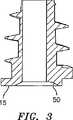
図1および図2を参照すると、ヘルニアメッシュを通じて、そしてヒト組織への無外傷性挿入のために適切なヘルニアタックが開示されている。ヘルニアタック10は、概して、細長いバレル部分12を備え、この細長いバレル部分は、キャップまたはヘッド14をバレル部分12の近位端部16に有する。バレル部分12は、ヘッドから遠位方向にのび、そして好ましくは、テーパ状である。デテントが、駆動装置の受容のためにヘッド14の近位表面15に形成され得る。好ましくは、バレル部分12およびヘッドキャップ14が、それを通過する通しボア18を規定する。通しボア18は、ヘッドキャップ14の近位末端20から、バレル部分12の遠位端部にまでのびる。Detailed Description of Preferred Embodiments
With reference to FIGS. 1 and 2, a hernia tack suitable for atraumatic insertion through a hernia mesh and into human tissue is disclosed. The
好ましくは、遠位端部22は、平滑であるかまたは丸めこまれ削られており、タック10が設置されるときに、組織を外傷すること、およびメッシュに損傷を与えることを回避する。遠位端部22は、無外傷性の移動を形成し、駆動ドライブロッドの先端が、挿入の間のメッシュおよび組織の破断を防止する。タック10は、任意の生体適合性材料から形成され得、そして好ましくは吸収性の材料から形成され得る。ヘルニアタック10の組織内への挿入および保持を容易にするために、バレル部分12には、組織ネジ山24が提供され、この組織ネジ山は、組織ネジ山24の遠位端部28において前縁26を、および組織ネジ山24の近位端部32に後縁30を有する。ヘルニアメッシュタックにおける組織ネジ山の使用は、組織に対してより大きな表面を有する領域が組織から押し出されることを防止することを可能にする。これは、タックの先行技術のタイプに比べて明らかな利点である。組織ネジ山24の前縁26は、ばれる部分12の遠位端部22に向けてテーパ状にされており、タック10をヘルニアメッシュおよび駆動装置によって空けられた組織孔を通じた回転を容易にする。この駆動装置は、以下により詳細に考察される。 Preferably, the
適切な駆動装置を備えるヘルニアタック10を利用するために、ヘッド14には、駆動ネジ山34が提供される。駆動ネジ山34は、駆動ネジ山34の遠位端部38において前縁36を、および駆動ネジ山34の近位端部42において後縁を有する。駆動ネジ山34の最大直径は、組織ネジ山24の最大直径よりも長く、その結果、タック10が駆動装置により回転するときに、組織ネジ山24が駆動装置に接触せず、そしてネジ山24は損傷を受けない。 To utilize the
図4および図5を参照すると、以下に記載される駆動装置は、駆動ロッドを、ヘッド14中のデテントへとまたは通しボア18を通じて通過させ、タック10を回転させるように構成される。示されているように、通しボア18は、弧状部分44および平坦部分46を有し、これらは、組み合わされて、概してD形状の通しボアを形成する。これは、通しボア18の内側表面に類似の形状の駆動ロッドが係合し、タック10を回転させることを可能にする。 With reference to FIGS. 4 and 5, the drive described below is configured to cause the drive rod to pass through a detent in the
組織ネジ山24は、近位表面48を有し、この表面は、バレル部分12に対してほぼ直角すなわち90°の角度で方向付けられている。これは、概して、組織と係合する概して平坦な表面領域を提供し、タック10が組織から押し出されるのを回避する。図7を一瞬の間参照すると。ネジ山24の遠位面49は、タック10の挿入を容易にするように、バレル部分12と鈍角を形成する。
図3に示されるように、ヘッド14の近位端部は、面取りされた表面50を有し、挿入ツール(例えば、駆動ロッド)を、通しボア18の中に受容することを容易にする。 As shown in FIG. 3, the proximal end of the
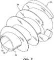
今度は図6および図7を参照すると、駆動ネジ山34が、より明瞭に例示されている。示されるように、駆動ネジ山34の前縁36および後縁40は、丸められ、その結果、駆動装置における挿入を容易にすることを促進する。さらに、後縁40は、ヘッド14の近位表面15でフラッシュされて、挿入装置によりタック10との再係合を容易にして、タック10の取りはずしを容易にする。 Turning now to FIGS. 6 and 7, the
図7および図8を参照すると、組織ネジ山24の後縁30および駆動ネジ山34の前縁36が不連続であり、そして1つの連続したネジ山を形成しないことが観察され得る。特に、駆動ネジ山34のテーパ状縁37は、駆動ネジ山34が、組織ネジ山24の後縁30が組織中に完全に挿入された後に組織へと連続することを防止する。図8はまた、D形状の通しボア18を示す。 With reference to FIGS. 7 and 8, it can be observed that the trailing
図9は、組織ネジ山24の概して平坦な近位表面48、および組織ネジ山24と駆動ネジ山34との間の移動ゾーン51を例示する。 FIG. 9 illustrates the generally flat
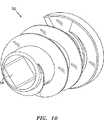
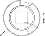
今度は図10および図11を参照すると、ヘルニアタック52の別の実施形態が例示されている。このヘルニアタック52は、ヘルニアタック10と、ほとんどの観点において同一である。しかし、ヘルニアタック52は、異なるスタイルの駆動装置との係合のための正方形の形の通しボア54を備える。通しボア54の正方形の形状は、係合する挿入ツールのためにより大きな表面積を提供する。このことは、通しボア54がストリップする可能性なしに、硬い組織へとタック52を駆動させるのを支援し得る。 Referring now to FIGS. 10 and 11, another embodiment of
同様に、今度は図12を参照すると、別のタック56の末端図が例示されている。これは、多角形形状の通しボア58を有し、挿入装置との係合のためにさらにより広い表面積を提供する。種々の他の通しボア形状(例えば、楕円、星型など)が提供されて、種々の挿入装置とともに作動し得る。通しボアの断面積としては、任意の非環状形状が本明細書において企図される。 Similarly, referring now to FIG. 12, an end view of another tack 56 is illustrated. This has a polygonal shaped through
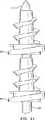
図13を参照すると、異なるスタイルの組織ネジ山を有する手術タックの別の実施形態が開示されている。タック60は、概して、バレル部分62およびヘッド64を備える。ヘッド64は、駆動ネジ山65を有し、挿入ツールにおけるネジ山と係合する。タック60のこの実施形態において、組織ネジ山66の近位表面68は、概して、バレル部分62に関して鈍角を形成する。組織ネジ山66のこの角度は、タック60が組織およびメッシュから取り出されるかまたは戻される必要がある状況においてその状況を支援し得る。ネジ山66の遠位表面69は、示されるように、バレル部分62に対して実質的に垂直に方向付けられ得る。組織ネジ山の近位表面68および遠位表面69のいずれかまたは両方は、バレル部分62と90°未満の角度を形成して、組織中にタック60を固定するのを支援することができる。 Referring to FIG. 13, another embodiment of a surgical tack having different styles of tissue threads is disclosed. The
今度は図14を参照すると、手術用タックのさらに別の実施形態が開示されている。タック70は、本明細書に上記されるタック10およびタック60に類似しており、そして概して、ヘッド74を有するバレル部分72を備える。このヘッド74は、駆動ネジ山75を有し、挿入装置におけるネジ山と係合する。本体部分72に形成された組織ネジ山76は、遠位表面78を備え、この表面は、バレル部分72に対して鈍角を形成する。このことは、タック70がメッシュを通じそして組織へと駆動されることを支援し得る。示されるように、組織ネジ山76の近位表面は、バレル部分72に対して垂直に方向付けられ得る。 Referring now to FIG. 14, yet another embodiment of a surgical tack is disclosed. The
今度は図15を参照すると、タック適用装置において使用するための駆動ロッド80が提示されている。駆動ロッド84は、ヘルニアメッシュおよび組織に単一のタックを適用するように構成された挿入ツールにおいて使用される。駆動ロッド80は、概して、外科手術装置の作動機構によって係合されるように構成され、その結果、その装置の動作が駆動ロッド80を回転させる近位端部部分82を備える。駆動ロッド80は、中心部分84および遠位部分86を備える。この中心部分84は、近位端部部分82から遠位方向に伸び、そして遠位部分86は、中心部分84から遠位方向にのびる。好ましくは、遠位部分86は、鋭い組織貫通先端88において終わる。 Referring now to FIG. 15, a drive rod 80 for use in a tack application device is presented. The
図16および図17に最もよく示されるように、駆動ロッド80の遠位断面86は、平坦な部分90および弧状部分92を備える。これらの部分は、概してD形状を形成し、その結果、タックの概してD形状通しボアに係合する。図18に最もよく示されるように、アバットメント表面94が、中心部分84の遠位端部96と遠位部分86の近位端部98との間に形成される。このアバットメント表面94は、タックのヘッドの近位表面と係合するように構成される。 As best shown in FIGS. 16 and 17, the
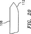
今度は図18〜図20を参照し、図18をまず参照すると、多重タックとともに用いるための駆動ロッド100が示されている。駆動ロッド100は、概して、近位端部102および遠位端部104を備える。アバットメント表面106が、遠位部分104と近位部分102との間に形成されて、タックと係合する。遠位部分104は、多重タックをそれに沿って受容するように十分に細長い。 Reference is now made to FIGS. 18-20, and with reference first to FIG. 18, a
図19を参照すると、遠位部分104は、平坦表面108と弧状表面110とを備える。この表面は、以前に開示されたヘルニアタックの通しボアと係合するように構成される。図20に示されるように、遠位部分104は、とがった遠位端部112を有する。 Referring to FIG. 19, the
図21を参照すると、駆動ロッド114に提供された一対のヘルニアタック60が例示される。 Referring to FIG. 21, a pair of hernia tacks 60 provided on the drive rod 114 are illustrated.
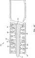
図22を参照すると、ヘルニアメッシュおよび組織に多重手術用タック60を提供するための挿入ツールの遠位端部が開示されている。挿入ツール120は、外側チューブ122内に位置づけされた回転可能な駆動ロッド100を有する、外側チューブ122を備える。上記において考察されたように、種々の公知のハンドル機構が提供されて、駆動ロッド100を外側チューブ122に対して回転させることができる。1つの公知のデバイスは、米国特許第5,582,616号(Bolduc)に開示されている。駆動ロッド100は、とがった遠位端部112を備え、最初に組織およびメッシュに孔を空けることを容易にする。示されるように、挿入ツール120は、内側ネジ山124を備え、このネジ山は、タック60のヘッド64の駆動ネジ山65と係合するように構成される。内側ネジ山124は、外側チューブ122において一体化されて形成され得る。内側ネジ山124は、外側チューブ122の内側表面に沿って完全にまたは部分的にのび得ることが留意されるべきである。ネジ山124がチューブ122の遠位端部においてのみ提供される場合、バネを用いて、チューブ122におけるネジ山124へむけて遠位方向に偏向され得る。内側ネジ山124の遠位端部125は、チューブ122の遠位端部を用いて位置づけされてフラッシュされる。このことにより、タックが設置後に取り出されることが必要な事象において、ヘッド64のネジ山65との内側ネジ山124の再係合が容易になる。明らかに示されるように、タック60が挿入ツール120に充填されるとき、組織ネジ山66は、内側ネジ山124と接触せず、そしてそれによって損傷を受けない。 Referring to FIG. 22, the distal end of an insertion tool for providing multiple
図23を参照すると、使用される場合、ハンドル126、ハンドル126から遠二方向にのびる細長いチューブ122、および内側ロッド100を回転するように構成されたアクチュエータ128を有する挿入ツール120が位置づけされ、その結果、とがった遠位端部112は、メッシュmおよびその下にある組織tに対して存在し、そしてヘルニア欠損部dを覆う。その後、ハンドル機構(示さず)が起動され、駆動ロッド100を外側チューブ212に関して回転させる。このことは、タック60のヘッドキャップ64の駆動ネジ山65が、内側ネジ山124と係合させることを生じ、そしてタック60が、メッシュmを通じて、そして組織t中へと駆動されることを生じる。上記のように、タック60は、駆動ロッド100の周囲のばねによって、遠位方向に偏向され得、そして内側ネジ山を部分的にまたは実質的に外側チューブ122の全長に沿って提供することによって遠位方向へと移動され得る。 Referring to FIG. 23, when used, an
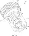
今度は図24を参照すると、ヘルニアタックおよび挿入ツールの展示モデルが開示されている。これらを用いて、直径が数ミリメートルのオーダーの非常に小さな実際のタックが、挿入ツールから出て見本の組織およびメッシュへとどのように駆動されるかを示すことができる。展示モデル130は、挿入ツール132およびタック134を備える。挿入ツール130は、内側ネジ山138を有する外側チューブ136を有する。本明細書において上記される挿入ツールと同様に、ネジ山138は、外側チューブ136、または外側チューブ136の内側表面に対して固定された別個の要素において一体化されて形成され得る。さらに、ネジ山138は、外側チューブ136を通じて完全にのびることが企図されるものの、ネジ山138は、チューブ136の遠位端部においてのみ提供され得、そしてばねまたは他の手段(示さず)が、外側チューブ136内に遠位方向にタックを偏向させるように提供され得る。 Referring now to FIG. 24, a display model of the hernia tack and insertion tool is disclosed. These can be used to show how very small actual tacks on the order of a few millimeters in diameter are driven out of the insertion tool and into the sample tissue and mesh. The
挿入ツール132はまた、そこから遠位方向にのび、そして内側チューブを通過する駆動ロッド142を有する駆動ノブ140を備える。駆動ロッド142は、とがった遠異端部を有して、組織の穴あけを刺激する。駆動ロッド142はまた、弧状および平坦な部分を有し、これらは、本明細書において上記した駆動ロッド100と類似のタックと係合するように構成される。タック134は、通しボア144を有して、駆動ロッド142を受容する。 The insertion tool 132 also includes a
タックおよびアプライヤの使用を実演するために、タック134を、チューブ136に配置し、そして挿入ツール132を操作して、タック134の通しボア150中の駆動ロッド142に配置した。ついで、ノブ140を回転して、タック134をチューブ136から駆動させた。 In order to demonstrate the use of the tack and applier, the
種々の改変が、本明細書において開示された実施形態においてなされ得ることが理解される。例えば、上記のように、タックにおける通しボアのための他の構成、および組織ネジ山の種々の角度がタックに提供され得る。従って、上記記載は、限定と解釈されるべきでなく、好ましい実施形態の例示としてのみ解釈されるべきである。当業者は、添付の特許請求の範囲の範囲および趣旨内において、他の改変を企図する。 It will be understood that various modifications may be made in the embodiments disclosed herein. For example, as described above, other configurations for through bores in the tack, and various angles of tissue threads can be provided to the tack. Therefore, the above description should not be construed as limiting, but merely as exemplifications of preferred embodiments. Those skilled in the art will envision other modifications within the scope and spirit of the claims appended hereto.
種々の実施形態が、図面を参照して本明細書において記載される。
Claims (2)
Translated fromJapaneseその外側表面に形成される駆動ネジ山を有するヘッド;
該ヘッドからのびるテーパ状のバレル部分であって、その外側表面に形成される組織係合ネジ山を有するバレル部分;および
該ヘッドおよび該テーパ状のバレル部分を通ってのびる通しボアであって、非環状の断面を有する該通しボア、
を備える、外科用タック。Surgical tack forattaching material to tissue , including:
A headhaving drive threads formed on its outer surface ;
A buildingtapered barrel portionof the heador,etal.,A barrel portion having a tissue engaging thread formed on its outer surface;a in through bores extending through and thehead and said tapered barrel portionThe through-bore having a non-circular cross-section ,
Equipped with a, tuck surgical.
Applications Claiming Priority (2)
| Application Number | Priority Date | Filing Date | Title |
|---|---|---|---|
| US38811902P | 2002-06-11 | 2002-06-11 | |
| PCT/US2003/018739WO2003103507A2 (en) | 2002-06-11 | 2003-06-11 | Hernia mesh tacks |
Publications (3)
| Publication Number | Publication Date |
|---|---|
| JP2005529650A JP2005529650A (en) | 2005-10-06 |
| JP2005529650A5 JP2005529650A5 (en) | 2006-07-20 |
| JP4319980B2true JP4319980B2 (en) | 2009-08-26 |
Family
ID=29736427
Family Applications (1)
| Application Number | Title | Priority Date | Filing Date |
|---|---|---|---|
| JP2004510634AExpired - Fee RelatedJP4319980B2 (en) | 2002-06-11 | 2003-06-11 | Hernia mesh tack |
Country Status (8)
| Country | Link |
|---|---|
| US (7) | US7867252B2 (en) |
| EP (4) | EP1511427B1 (en) |
| JP (1) | JP4319980B2 (en) |
| AU (6) | AU2003251514B2 (en) |
| CA (1) | CA2489340C (en) |
| DE (3) | DE60319755T2 (en) |
| ES (3) | ES2279156T3 (en) |
| WO (1) | WO2003103507A2 (en) |
Families Citing this family (154)
| Publication number | Priority date | Publication date | Assignee | Title |
|---|---|---|---|---|
| US7867186B2 (en) | 2002-04-08 | 2011-01-11 | Glaukos Corporation | Devices and methods for treatment of ocular disorders |
| US6638239B1 (en) | 2000-04-14 | 2003-10-28 | Glaukos Corporation | Apparatus and method for treating glaucoma |
| AU2002258754B2 (en) | 2001-04-07 | 2006-08-17 | Glaukos Corporation | Glaucoma stent and methods thereof for glaucoma treatment |
| US7331984B2 (en) | 2001-08-28 | 2008-02-19 | Glaukos Corporation | Glaucoma stent for treating glaucoma and methods of use |
| AU2002348033B2 (en) | 2001-10-23 | 2008-05-29 | Covidien Lp | Surgical fasteners |
| ES2279156T3 (en) | 2002-06-11 | 2007-08-16 | Tyco Healthcare Group Lp | MALE TIGHTS FOR HERNIAS. |
| US8926637B2 (en) | 2003-06-13 | 2015-01-06 | Covidien Lp | Multiple member interconnect for surgical instrument and absorbable screw fastener |
| US7670362B2 (en) | 2003-06-13 | 2010-03-02 | Tyco Healthcare Group Lp | Multiple member interconnect for surgical instrument and absorbable screw fastener |
| US7758612B2 (en)* | 2004-04-27 | 2010-07-20 | Tyco Healthcare Group Lp | Surgery delivery device and mesh anchor |
| US10478179B2 (en)* | 2004-04-27 | 2019-11-19 | Covidien Lp | Absorbable fastener for hernia mesh fixation |
| US20060129152A1 (en)* | 2004-12-10 | 2006-06-15 | Shipp John I | Absorbable Anchor for Hernia Mesh Fixation |
| US8114099B2 (en) | 2004-04-27 | 2012-02-14 | Tyco Healthcare Group Lp | Absorbable anchor for hernia mesh fixation |
| DE102004022590A1 (en)* | 2004-05-07 | 2005-12-01 | Feussner, Hubertus, Prof.Dr.med. | Blind rivet for adaptation of biological tissue and device for setting the same, in particular through the instrument channel of an endoscope |
| US20050278023A1 (en)* | 2004-06-10 | 2005-12-15 | Zwirkoski Paul A | Method and apparatus for filling a cavity |
| US7905904B2 (en) | 2006-02-03 | 2011-03-15 | Biomet Sports Medicine, Llc | Soft tissue repair device and associated methods |
| US9017381B2 (en) | 2007-04-10 | 2015-04-28 | Biomet Sports Medicine, Llc | Adjustable knotless loops |
| US7749250B2 (en) | 2006-02-03 | 2010-07-06 | Biomet Sports Medicine, Llc | Soft tissue repair assembly and associated method |
| US8303604B2 (en) | 2004-11-05 | 2012-11-06 | Biomet Sports Medicine, Llc | Soft tissue repair device and method |
| US8118836B2 (en) | 2004-11-05 | 2012-02-21 | Biomet Sports Medicine, Llc | Method and apparatus for coupling soft tissue to a bone |
| US8137382B2 (en) | 2004-11-05 | 2012-03-20 | Biomet Sports Medicine, Llc | Method and apparatus for coupling anatomical features |
| US8298262B2 (en) | 2006-02-03 | 2012-10-30 | Biomet Sports Medicine, Llc | Method for tissue fixation |
| US7909851B2 (en) | 2006-02-03 | 2011-03-22 | Biomet Sports Medicine, Llc | Soft tissue repair device and associated methods |
| US9801708B2 (en) | 2004-11-05 | 2017-10-31 | Biomet Sports Medicine, Llc | Method and apparatus for coupling soft tissue to a bone |
| US7658751B2 (en) | 2006-09-29 | 2010-02-09 | Biomet Sports Medicine, Llc | Method for implanting soft tissue |
| US8128658B2 (en) | 2004-11-05 | 2012-03-06 | Biomet Sports Medicine, Llc | Method and apparatus for coupling soft tissue to bone |
| US8361113B2 (en) | 2006-02-03 | 2013-01-29 | Biomet Sports Medicine, Llc | Method and apparatus for coupling soft tissue to a bone |
| US8088130B2 (en) | 2006-02-03 | 2012-01-03 | Biomet Sports Medicine, Llc | Method and apparatus for coupling soft tissue to a bone |
| US7935137B2 (en) | 2004-12-08 | 2011-05-03 | Depuy Spine, Inc. | Locking bone screw and spinal plate system |
| US9078644B2 (en) | 2006-09-29 | 2015-07-14 | Biomet Sports Medicine, Llc | Fracture fixation device |
| US8562645B2 (en) | 2006-09-29 | 2013-10-22 | Biomet Sports Medicine, Llc | Method and apparatus for forming a self-locking adjustable loop |
| US11259792B2 (en) | 2006-02-03 | 2022-03-01 | Biomet Sports Medicine, Llc | Method and apparatus for coupling anatomical features |
| US8597327B2 (en) | 2006-02-03 | 2013-12-03 | Biomet Manufacturing, Llc | Method and apparatus for sternal closure |
| US8968364B2 (en) | 2006-02-03 | 2015-03-03 | Biomet Sports Medicine, Llc | Method and apparatus for fixation of an ACL graft |
| US9149267B2 (en) | 2006-02-03 | 2015-10-06 | Biomet Sports Medicine, Llc | Method and apparatus for coupling soft tissue to a bone |
| US10517587B2 (en) | 2006-02-03 | 2019-12-31 | Biomet Sports Medicine, Llc | Method and apparatus for forming a self-locking adjustable loop |
| US11311287B2 (en) | 2006-02-03 | 2022-04-26 | Biomet Sports Medicine, Llc | Method for tissue fixation |
| US9538998B2 (en) | 2006-02-03 | 2017-01-10 | Biomet Sports Medicine, Llc | Method and apparatus for fracture fixation |
| US8562647B2 (en) | 2006-09-29 | 2013-10-22 | Biomet Sports Medicine, Llc | Method and apparatus for securing soft tissue to bone |
| US8652172B2 (en) | 2006-02-03 | 2014-02-18 | Biomet Sports Medicine, Llc | Flexible anchors for tissue fixation |
| US8652171B2 (en) | 2006-02-03 | 2014-02-18 | Biomet Sports Medicine, Llc | Method and apparatus for soft tissue fixation |
| US8801783B2 (en) | 2006-09-29 | 2014-08-12 | Biomet Sports Medicine, Llc | Prosthetic ligament system for knee joint |
| US9408599B2 (en)* | 2006-02-03 | 2016-08-09 | Biomet Sports Medicine, Llc | Method and apparatus for coupling soft tissue to a bone |
| US9468433B2 (en) | 2006-02-03 | 2016-10-18 | Biomet Sports Medicine, Llc | Method and apparatus for forming a self-locking adjustable loop |
| US7862573B2 (en) | 2006-04-21 | 2011-01-04 | Darois Roger E | Method and apparatus for surgical fastening |
| WO2008010948A2 (en)* | 2006-07-18 | 2008-01-24 | Davol Inc. | Method and apparatus for surgical fastening |
| US8894661B2 (en) | 2007-08-16 | 2014-11-25 | Smith & Nephew, Inc. | Helicoil interference fixation system for attaching a graft ligament to a bone |
| US8348973B2 (en)* | 2006-09-06 | 2013-01-08 | Covidien Lp | Bioactive substance in a barbed suture |
| US8500818B2 (en) | 2006-09-29 | 2013-08-06 | Biomet Manufacturing, Llc | Knee prosthesis assembly with ligament link |
| US8672969B2 (en) | 2006-09-29 | 2014-03-18 | Biomet Sports Medicine, Llc | Fracture fixation device |
| US11259794B2 (en) | 2006-09-29 | 2022-03-01 | Biomet Sports Medicine, Llc | Method for implanting soft tissue |
| US9918826B2 (en) | 2006-09-29 | 2018-03-20 | Biomet Sports Medicine, Llc | Scaffold for spring ligament repair |
| EP2088976B1 (en) | 2006-11-10 | 2019-07-03 | Glaukos Corporation | Uveoscleral shunt |
| GB0625069D0 (en)* | 2006-12-15 | 2007-01-24 | Givaudan Sa | Compositions |
| US8800837B2 (en)* | 2007-04-13 | 2014-08-12 | Covidien Lp | Powered surgical instrument |
| US20080277445A1 (en)* | 2007-05-07 | 2008-11-13 | Zergiebel Earl M | Single fire tacker instrument |
| US20090118747A1 (en)* | 2007-11-05 | 2009-05-07 | Tyco Healthcare Group Lp | Novel surgical fastener |
| US8888810B2 (en) | 2008-02-20 | 2014-11-18 | Covidien Lp | Compound barb medical device and method |
| US8454653B2 (en) | 2008-02-20 | 2013-06-04 | Covidien Lp | Compound barb medical device and method |
| WO2010022060A1 (en) | 2008-08-19 | 2010-02-25 | Wilson-Cook Medical Inc. | Apparatus for removing lymph nodes or anchoring into tissue during a translumenal procedure |
| US12419632B2 (en) | 2008-08-22 | 2025-09-23 | Biomet Sports Medicine, Llc | Method and apparatus for coupling anatomical features |
| US12245759B2 (en) | 2008-08-22 | 2025-03-11 | Biomet Sports Medicine, Llc | Method and apparatus for coupling soft tissue to bone |
| US8192461B2 (en) | 2008-09-11 | 2012-06-05 | Cook Medical Technologies Llc | Methods for facilitating closure of a bodily opening using one or more tacking devices |
| US20100204729A1 (en)* | 2008-09-11 | 2010-08-12 | Ahmad Robert Hadba | Tapered Looped Suture |
| US8323316B2 (en) | 2008-10-09 | 2012-12-04 | Covidien Lp | Knotted suture end effector |
| WO2010053737A1 (en)* | 2008-10-29 | 2010-05-14 | Wilson-Cook Medical, Inc. | Endoscopic sheet delivery |
| US8377095B2 (en)* | 2008-12-05 | 2013-02-19 | Cook Medical Technologies, LLC | Tissue anchors for purse-string closure of perforations |
| AU2009324819B2 (en) | 2008-12-09 | 2014-04-17 | Cook Medical Technologies Llc | Retractable tacking device |
| CA2746651C (en)* | 2008-12-11 | 2014-07-15 | Tyler Evans Mclawhorn | Endoscopic sheet rolling system |
| EP2389122B1 (en) | 2008-12-19 | 2015-03-04 | Cook Medical Technologies LLC | Clip devices |
| FR2941144B1 (en)* | 2009-01-22 | 2012-04-27 | Sofradim Production | SURGICAL STAPLER FOR PREPOSITIONING AND ATTACHING TEXTILE PROSTHESIS, METHOD OF LOADING THE SAME, AND SELF-AGRIPPTING SURGICAL STRAIN |
| US8206291B2 (en) | 2009-03-27 | 2012-06-26 | Tyco Healthcare Group Lp | Portal device |
| CA2757554A1 (en) | 2009-04-03 | 2010-10-07 | Cook Medical Technologies Llc | Tissue anchors and medical devices for rapid deployment of tissue anchors |
| US8486093B2 (en)* | 2009-05-14 | 2013-07-16 | Cook Medical Technologies Llc | Systems and methods for securing a graft member to tissue using one or more tacking devices |
| WO2012071476A2 (en) | 2010-11-24 | 2012-05-31 | David Haffner | Drug eluting ocular implant |
| JP2012527970A (en) | 2009-05-28 | 2012-11-12 | クック メディカル テクノロジーズ エルエルシー | Hail-fastening device and hail-fastening device deployment method |
| US12096928B2 (en) | 2009-05-29 | 2024-09-24 | Biomet Sports Medicine, Llc | Method and apparatus for coupling soft tissue to a bone |
| US8459524B2 (en)* | 2009-08-14 | 2013-06-11 | Covidien Lp | Tissue fastening system for a medical device |
| US8979865B2 (en) | 2010-03-10 | 2015-03-17 | Smith & Nephew, Inc. | Composite interference screws and drivers |
| US9308080B2 (en) | 2010-03-10 | 2016-04-12 | Smith & Nephew Inc. | Composite interference screws and drivers |
| US9579188B2 (en) | 2010-03-10 | 2017-02-28 | Smith & Nephew, Inc. | Anchor having a controlled driver orientation |
| US9775702B2 (en) | 2010-03-10 | 2017-10-03 | Smith & Nephew, Inc. | Composite interference screws and drivers |
| US20110295282A1 (en)* | 2010-05-26 | 2011-12-01 | Tyco Healthcare Group Lp | Fastener and drive method for soft tissue repair |
| US9888920B2 (en)* | 2010-09-21 | 2018-02-13 | Sportwelding Gmbh | Connecting a plurality of tissue parts |
| MX344606B (en) | 2011-03-11 | 2016-12-20 | Smith & Nephew Inc | Trephine. |
| US12329373B2 (en) | 2011-05-02 | 2025-06-17 | Biomet Sports Medicine, Llc | Method and apparatus for soft tissue fixation |
| AU2012267924B2 (en)* | 2011-06-07 | 2016-08-11 | Smith & Nephew, Inc. | Surgical anchor delivery system |
| US9131936B2 (en)* | 2011-06-10 | 2015-09-15 | Ethicon, Inc. | Anchor tip orientation device and method |
| US9610109B2 (en)* | 2011-08-16 | 2017-04-04 | Howmedica Osteonics Corp. | Wedge shaped fracture fixation devices and methods for using the same |
| CA2849887A1 (en)* | 2011-09-26 | 2013-04-04 | Artack Medical (2013) Ltd. | Surgical fastening device and method |
| US9357991B2 (en) | 2011-11-03 | 2016-06-07 | Biomet Sports Medicine, Llc | Method and apparatus for stitching tendons |
| US9381013B2 (en) | 2011-11-10 | 2016-07-05 | Biomet Sports Medicine, Llc | Method for coupling soft tissue to a bone |
| US9314241B2 (en) | 2011-11-10 | 2016-04-19 | Biomet Sports Medicine, Llc | Apparatus for coupling soft tissue to a bone |
| US9486213B2 (en)* | 2011-11-14 | 2016-11-08 | Thd Lap Ltd. | Drive mechanism for articulating tacker |
| US8535339B2 (en) | 2011-12-18 | 2013-09-17 | Via Surgical Ltd. | Apparatus and method for suturing |
| CA2868341C (en) | 2012-03-26 | 2021-01-12 | Glaukos Corporation | System and method for delivering multiple ocular implants |
| ES2733939T3 (en)* | 2012-05-31 | 2019-12-03 | Via Surgical Ltd | Surgical fixation of variable depth |
| US9888913B2 (en) | 2012-05-31 | 2018-02-13 | Via Surgical Ltd. | Variable depth surgical fixation |
| US9351733B2 (en) | 2013-01-18 | 2016-05-31 | Covidien Lp | Surgical fastener applier |
| US9757119B2 (en) | 2013-03-08 | 2017-09-12 | Biomet Sports Medicine, Llc | Visual aid for identifying suture limbs arthroscopically |
| US9993245B2 (en) | 2013-03-11 | 2018-06-12 | Via Surgical Ltd. | Surgical tacker with quantity indicator |
| US9358010B2 (en) | 2013-03-12 | 2016-06-07 | Covidien Lp | Flex cable and spring-loaded tube for tacking device |
| US9867620B2 (en) | 2013-03-14 | 2018-01-16 | Covidien Lp | Articulation joint for apparatus for endoscopic procedures |
| US9427230B2 (en) | 2013-03-14 | 2016-08-30 | C.R. Bard, Inc. | Handling of fasteners within a surgical instrument |
| US9918827B2 (en) | 2013-03-14 | 2018-03-20 | Biomet Sports Medicine, Llc | Scaffold for spring ligament repair |
| US9655621B2 (en) | 2013-03-15 | 2017-05-23 | Covidien Lp | Surgical instrument for dispensing tacks and solution |
| US9155531B2 (en) | 2013-03-15 | 2015-10-13 | Smith & Nephew, Inc. | Miniaturized dual drive open architecture suture anchor |
| US9592151B2 (en) | 2013-03-15 | 2017-03-14 | Glaukos Corporation | Systems and methods for delivering an ocular implant to the suprachoroidal space within an eye |
| WO2014169058A1 (en) | 2013-04-09 | 2014-10-16 | Smith & Nephew, Inc | Open-architecture interference screw |
| US9351728B2 (en) | 2013-06-28 | 2016-05-31 | Covidien Lp | Articulating apparatus for endoscopic procedures |
| US10085746B2 (en) | 2013-06-28 | 2018-10-02 | Covidien Lp | Surgical instrument including rotating end effector and rotation-limiting structure |
| US9358004B2 (en) | 2013-06-28 | 2016-06-07 | Covidien Lp | Articulating apparatus for endoscopic procedures |
| US9668730B2 (en) | 2013-06-28 | 2017-06-06 | Covidien Lp | Articulating apparatus for endoscopic procedures with timing system |
| US20150032130A1 (en) | 2013-07-24 | 2015-01-29 | Covidien Lp | Expanding absorbable tack |
| US9526498B2 (en) | 2013-09-17 | 2016-12-27 | Covidien Lp | Surgical device with a trigger lockout mechanism device |
| US10285697B2 (en) | 2013-11-08 | 2019-05-14 | C.R. Bard, Inc. | Methods and apparatus for surgical fastening |
| US9445814B2 (en) | 2013-11-08 | 2016-09-20 | C.R. Bard, Inc. | Surgical fastener |
| US9615830B2 (en) | 2013-11-08 | 2017-04-11 | C.R. Bard, Inc. | Surgical fastener |
| US9675353B2 (en) | 2013-11-08 | 2017-06-13 | C.R. Bard, Inc. | Surgical fasteners and associated deployment devices |
| US10368870B2 (en)* | 2013-11-08 | 2019-08-06 | C.R. Bard, Inc. | Surgical fastener |
| US10335146B2 (en) | 2014-04-02 | 2019-07-02 | Coviden Lp | Surgical fastener applying apparatus, kits and methods for endoscopic procedures |
| US20150305738A1 (en) | 2014-04-28 | 2015-10-29 | Covidien Lp | Surgical fastener having a cap |
| USD768297S1 (en) | 2014-10-13 | 2016-10-04 | Ethicon, Inc. | Multi-barbed anchor |
| US10368860B2 (en) | 2014-11-21 | 2019-08-06 | Ethicon, Inc. | Absorbable surgical fasteners for securing prosthetic devices to tissue |
| US11090097B2 (en) | 2015-03-17 | 2021-08-17 | Covidien Lp | Connecting end effectors to surgical devices |
| ES2821006T3 (en) | 2015-04-23 | 2021-04-23 | Via Surgical Ltd | Surgical Fastener Locking and Delivery Mechanism |
| US10092286B2 (en) | 2015-05-27 | 2018-10-09 | Covidien Lp | Suturing loading unit |
| US10342651B2 (en) | 2015-06-04 | 2019-07-09 | Covidien Lp | Ventral hernia defect closure |
| KR20230104750A (en)* | 2015-12-16 | 2023-07-10 | 콘메드 코포레이션 | Knotless suture anchor and deployment device |
| EP3402412A1 (en)* | 2016-01-13 | 2018-11-21 | NeoSurgical Limited | Fixation device delivery system |
| CN107433547B (en)* | 2016-05-28 | 2021-01-15 | 富泰华工业(深圳)有限公司 | Screw releasing device |
| US11298123B2 (en) | 2016-10-21 | 2022-04-12 | Covidien Lp | Surgical end effectors |
| US10743859B2 (en) | 2016-10-21 | 2020-08-18 | Covidien Lp | Surgical end effectors |
| US10617409B2 (en) | 2016-10-21 | 2020-04-14 | Covidien Lp | Surgical end effectors |
| US10888309B2 (en)* | 2017-01-31 | 2021-01-12 | Covidien Lp | Surgical fastener devices with geometric tubes |
| JP6848632B2 (en)* | 2017-04-10 | 2021-03-24 | 株式会社ジェイテクト | Vehicle control device |
| US11160682B2 (en) | 2017-06-19 | 2021-11-02 | Covidien Lp | Method and apparatus for accessing matter disposed within an internal body vessel |
| USD854921S1 (en)* | 2017-09-12 | 2019-07-30 | Gripple Limited | Helical anchor |
| AU201811484S (en)* | 2017-09-12 | 2018-04-23 | Gripple Lmited | Fastener |
| US11116625B2 (en) | 2017-09-28 | 2021-09-14 | Glaukos Corporation | Apparatus and method for controlling placement of intraocular implants |
| CN110573117B (en) | 2017-10-06 | 2021-10-26 | 格劳科斯公司 | Systems and methods for delivering multiple ocular implants |
| US10842603B1 (en) | 2017-10-16 | 2020-11-24 | David Lee Street | Sutureless ventral hernia meshing system and method of fixation |
| USD846738S1 (en) | 2017-10-27 | 2019-04-23 | Glaukos Corporation | Implant delivery apparatus |
| CN108066041B (en)* | 2018-01-05 | 2024-04-16 | 北京博辉瑞进生物科技有限公司 | Absorbable nail and repair fixer |
| US11298126B2 (en) | 2018-05-02 | 2022-04-12 | Covidien Lp | Shipping wedge for end effector installation onto surgical devices |
| US11116500B2 (en) | 2018-06-28 | 2021-09-14 | Covidien Lp | Surgical fastener applying device, kits and methods for endoscopic procedures |
| US11389159B2 (en) | 2018-09-21 | 2022-07-19 | Covidien Lp | Powered surgical tack applier |
| US11234701B2 (en) | 2018-09-21 | 2022-02-01 | Covidien Lp | Powered surgical tack applier |
| WO2020206316A1 (en)* | 2019-04-04 | 2020-10-08 | Surgimatix, Inc. | Surgical fastening device |
| US11523817B2 (en) | 2019-06-27 | 2022-12-13 | Covidien Lp | Endoluminal pursestring device |
| USD944984S1 (en) | 2019-12-19 | 2022-03-01 | Covidien Lp | Tubular positioning guide |
| US11197675B2 (en) | 2019-12-19 | 2021-12-14 | Covidien Lp | Positioning guide for surgical instruments and surgical instrument systems |
| USD944985S1 (en) | 2019-12-19 | 2022-03-01 | Covidien Lp | Positioning guide cuff |
| CN114376635A (en) | 2020-10-05 | 2022-04-22 | 柯惠Lp公司 | Electric Surgical Nail Applicator |
| WO2022096753A1 (en) | 2020-11-09 | 2022-05-12 | Medos International Sarl | Multiple set screw insertion instrument and methods |
Family Cites Families (178)
| Publication number | Priority date | Publication date | Assignee | Title |
|---|---|---|---|---|
| US373074A (en)* | 1887-11-15 | Wood-screw | ||
| US2167558A (en)* | 1937-06-24 | 1939-07-25 | Lamson & Sessions Co | Self-tapping bolt |
| US2391792A (en)* | 1942-01-23 | 1945-12-25 | Johns Manville | Wall construction and fastener therefor |
| US2670770A (en)* | 1950-07-27 | 1954-03-02 | Du Mont Allen B Lab Inc | Screw holding and feeding means for power-operated screw drivers |
| US3008554A (en)* | 1958-02-13 | 1961-11-14 | Samuel K Hodgson | Nut and retainer for workpieces with non-parallel faces |
| US3236157A (en)* | 1962-03-15 | 1966-02-22 | Gunver Mfg Company | Fluid motors |
| US3233500A (en)* | 1962-10-23 | 1966-02-08 | American Fastener Corp | Screw with main shank threads of a given pitch merging with threads of unlike pitch on a tapered bottom end of the screw shank |
| US3289290A (en)* | 1963-03-14 | 1966-12-06 | Raymond P Sandor | Method and apparatus for installing fasteners |
| US3357094A (en)* | 1964-12-04 | 1967-12-12 | Nat Screw & Mfg Company | Blind fastener |
| US3403738A (en)* | 1966-11-01 | 1968-10-01 | Aro Corp | Drill/scredriver with impact mechanism |
| DE1816949B1 (en) | 1968-12-24 | 1970-05-27 | Piv Antrieb Reimers Kg Werner | Conical pulley belt drive |
| AT305922B (en)* | 1969-02-18 | 1973-03-26 | Gkn Screws Fasteners Ltd | Power operated tool |
| US3698058A (en)* | 1971-05-14 | 1972-10-17 | Gte Automatic Electric Lab Inc | Apparatus for applying with clamp terminal clips of the flanged tubular type |
| US3917323A (en)* | 1973-09-12 | 1975-11-04 | John P Morgan | Connecting apparatus for an air duct system |
| DE2910546C3 (en) | 1979-03-17 | 1982-05-27 | P.I.V. Antrieb Werner Reimers GmbH & Co KG, 6380 Bad Homburg | Conical pulley belt drive |
| US4507817A (en)* | 1981-10-08 | 1985-04-02 | Staffeld Stanley E | Connector and insertion tool |
| US4581962A (en)* | 1982-06-07 | 1986-04-15 | Marbourg Edgar F | Tool to capture, control and manipulate threaded fasteners |
| US4456005A (en)* | 1982-09-30 | 1984-06-26 | Lichty Terry K | External compression bone fixation device |
| US4537185A (en)* | 1983-06-10 | 1985-08-27 | Denis P. Stednitz | Cannulated fixation screw |
| US4532926A (en)* | 1983-06-20 | 1985-08-06 | Ethicon, Inc. | Two-piece tissue fastener with ratchet leg staple and sealable latching receiver |
| DE3513544A1 (en) | 1985-04-16 | 1986-10-16 | Walther & Cie AG, 5000 Köln | METHOD FOR DEPOSITING NITROGEN OXIDES |
| USD296655S (en)* | 1985-08-09 | 1988-07-12 | Matsushita Electric Works, Ltd. | Combined electric drill and screwdriver |
| US4884572A (en)* | 1986-05-20 | 1989-12-05 | Concept, Inc. | Tack and applicator for treating torn bodily material in vivo |
| US4740123A (en)* | 1987-02-09 | 1988-04-26 | Phillips Plastics Corporation | Re-usable expandable plastic nut for two-piece fastener |
| US4844606A (en)* | 1987-05-29 | 1989-07-04 | Smith Franklin G | Temple fastener for eyeglass frames |
| MX170527B (en)* | 1987-11-03 | 1993-08-30 | Synthes Ag | IMPLEMENTATION FOR OSTEOSYNTHESIS |
| US4878794A (en)* | 1988-03-15 | 1989-11-07 | John W. Hall, Jr. | Collated screw fasteners |
| DE3811345C1 (en)* | 1988-04-02 | 1989-09-07 | Aesculap Ag, 7200 Tuttlingen, De | |
| US4858601A (en)* | 1988-05-27 | 1989-08-22 | Glisson Richard R | Adjustable compression bone screw |
| US5129906A (en)* | 1989-09-08 | 1992-07-14 | Linvatec Corporation | Bioabsorbable tack for joining bodily tissue and in vivo method and apparatus for deploying same |
| JPH0716090Y2 (en)* | 1989-09-12 | 1995-04-12 | 山喜産業株式会社 | Tapping screw |
| US5019079A (en)* | 1989-11-20 | 1991-05-28 | Zimmer, Inc. | Bone screw |
| US5236563A (en) | 1990-06-18 | 1993-08-17 | Advanced Surface Technology Inc. | Surface-modified bioabsorbables |
| US7208013B1 (en)* | 1990-06-28 | 2007-04-24 | Bonutti Ip, Llc | Composite surgical devices |
| US5203864A (en)* | 1991-04-05 | 1993-04-20 | Phillips Edward H | Surgical fastener system |
| FR2682281B1 (en)* | 1991-10-11 | 1997-01-03 | Sofamor | PERCUTANEOUS SCREW, INTENDED TO SUPPORT IN PARTICULAR A STEREOTAXY FRAMEWORK |
| US5259395A (en)* | 1992-01-15 | 1993-11-09 | Siemens Pacesetter, Inc. | Pacemaker lead with extendable retractable lockable fixing helix |
| US5425733A (en)* | 1992-02-19 | 1995-06-20 | Arthrex, Inc. | Interference screw with rounded back end and cannulated sheath for endosteal fixation of ligaments |
| US5211647A (en)* | 1992-02-19 | 1993-05-18 | Arthrex Inc. | Interference screw and cannulated sheath for endosteal fixation of ligaments |
| US5207545A (en)* | 1992-03-30 | 1993-05-04 | Motorola, Inc. | Threaded fastener |
| US5192288A (en)* | 1992-05-26 | 1993-03-09 | Origin Medsystems, Inc. | Surgical clip applier |
| US5381943A (en) | 1992-10-09 | 1995-01-17 | Ethicon, Inc. | Endoscopic surgical stapling instrument with pivotable and rotatable staple cartridge |
| US5354299A (en)* | 1992-12-07 | 1994-10-11 | Linvatec Corporation | Method of revising a screw in a tunnel |
| US6030162A (en)* | 1998-12-18 | 2000-02-29 | Acumed, Inc. | Axial tension screw |
| US5354292A (en)* | 1993-03-02 | 1994-10-11 | Braeuer Harry L | Surgical mesh introduce with bone screw applicator for the repair of an inguinal hernia |
| DE4307633C1 (en)* | 1993-03-11 | 1994-05-19 | Pennig Dietmar | Screw for locking marrow-cavity pin in position - has threaded section of shank near head and opposite thread on head with unthreaded section of shank between |
| US5496329A (en)* | 1993-09-08 | 1996-03-05 | Alpha Surgical, Inc. | Method and apparatus for implanting a medical ventilation tube |
| AU1011595A (en)* | 1994-01-13 | 1995-07-20 | Ethicon Inc. | Spiral surgical tack |
| US5456685A (en)* | 1994-02-14 | 1995-10-10 | Smith & Nephew Dyonics, Inc. | Interference screw having a tapered back root |
| US6001101A (en)* | 1994-07-05 | 1999-12-14 | Depuy France | Screw device with threaded head for permitting the coaptation of two bone fragments |
| US5582616A (en) | 1994-08-05 | 1996-12-10 | Origin Medsystems, Inc. | Surgical helical fastener with applicator |
| US5730744A (en)* | 1994-09-27 | 1998-03-24 | Justin; Daniel F. | Soft tissue screw, delivery device, and method |
| US5464427A (en)* | 1994-10-04 | 1995-11-07 | Synthes (U.S.A.) | Expanding suture anchor |
| US5536127A (en)* | 1994-10-13 | 1996-07-16 | Pennig; Dietmar | Headed screw construction for use in fixing the position of an intramedullary nail |
| US6053918A (en)* | 1994-10-25 | 2000-04-25 | General Orthopedics | Apparatus and method for fastening an intramedullary nail to a bone |
| US5840078A (en)* | 1995-03-01 | 1998-11-24 | Yerys; Paul | Method and apparatus for mechanical attachment of soft tissue to bone tissue |
| US5697929A (en)* | 1995-10-18 | 1997-12-16 | Cross Medical Products, Inc. | Self-limiting set screw for use with spinal implant systems |
| JPH09149906A (en) | 1995-11-29 | 1997-06-10 | Nagoya Rashi Seisakusho:Kk | Tool for curing bone disease |
| DE29520312U1 (en) | 1995-12-21 | 1996-02-08 | Leibinger Medizintech | Bone screw |
| WO1997029706A1 (en)* | 1996-02-16 | 1997-08-21 | Smith & Nephew, Inc. | Graft anchor |
| US5868749A (en)* | 1996-04-05 | 1999-02-09 | Reed; Thomas M. | Fixation devices |
| US5743914A (en)* | 1996-06-06 | 1998-04-28 | Skiba; Jeffry B. | Bone screw |
| US6117162A (en)* | 1996-08-05 | 2000-09-12 | Arthrex, Inc. | Corkscrew suture anchor |
| US6319270B1 (en) | 1996-08-05 | 2001-11-20 | Arthrex, Inc. | Headed bioabsorbable tissue anchor |
| US6569188B2 (en)* | 1996-08-05 | 2003-05-27 | Arthrex, Inc. | Hex drive bioabsorbable tissue anchor |
| US7611521B2 (en) | 1996-09-13 | 2009-11-03 | Tendon Technology, Ltd. | Apparatus and methods for tendon or ligament repair |
| US6042314A (en)* | 1996-09-17 | 2000-03-28 | Windware Inc. | Fastener and method of operation thereof for installing a thin layer of material at an adjustable distance from a support |
| US5830221A (en)* | 1996-09-20 | 1998-11-03 | United States Surgical Corporation | Coil fastener applier |
| DE69736601T2 (en)* | 1996-09-20 | 2007-12-27 | United States Surgical Corporation, Norwalk | Surgical device for attaching spiral clips |
| US5971985A (en)* | 1997-09-12 | 1999-10-26 | Ace Surgical Supply Co., Inc. | Bone attachment device for use with tissue grafts and membranes |
| US5891146A (en)* | 1997-10-15 | 1999-04-06 | Applied Biological Concepts, Inc. | Wedge orthopedic screw |
| US6158938A (en)* | 1998-03-11 | 2000-12-12 | Illinois Tool Works Inc | Anti-cross threading fastener |
| US8075570B2 (en) | 2001-11-28 | 2011-12-13 | Aptus Endosystems, Inc. | Intraluminal prosthesis attachment systems and methods |
| US7591842B2 (en) | 1998-03-13 | 2009-09-22 | Aptus Endosystems, Inc. | Endovascular prosthesis with suture holder |
| US7491232B2 (en) | 1998-09-18 | 2009-02-17 | Aptus Endosystems, Inc. | Catheter-based fastener implantation apparatus and methods with implantation force resolution |
| US6398785B2 (en)* | 1998-04-14 | 2002-06-04 | Joseph Edward Carchidi | Apparatus for rigidly fixing craniomaxillofacial tissue grafts and bone plates |
| US6059799A (en)* | 1998-06-25 | 2000-05-09 | United States Surgical Corporation | Apparatus for applying surgical clips |
| US6355066B1 (en)* | 1998-08-19 | 2002-03-12 | Andrew C. Kim | Anterior cruciate ligament reconstruction hamstring tendon fixation system |
| WO2000016701A1 (en) | 1998-09-18 | 2000-03-30 | United States Surgical Corporation | Endovascular fastener applicator |
| US6099529A (en)* | 1998-10-26 | 2000-08-08 | Musculoskeletal Transplant Foundation | Allograft bone fixation screw method and apparatus |
| CA2351531C (en)* | 1998-11-18 | 2007-04-24 | General Surgical Innovations, Inc. | Helical fastener and applicator for surgical procedures |
| US6402757B1 (en)* | 1999-03-12 | 2002-06-11 | Biomet, Inc. | Cannulated fastener system for repair of bone fracture |
| AU4067800A (en)* | 1999-04-02 | 2000-10-23 | Osteotech, Inc. | Surgical bone screw |
| FR2792521B1 (en)* | 1999-04-22 | 2001-08-31 | New Deal | COMPRESSION OSTEOSYNTHESIS SCREWS AND IMPLEMENTATION ANCILLARY |
| US6096060A (en)* | 1999-05-20 | 2000-08-01 | Linvatec Corporation | Bioabsorbable threaded soft tissue anchor system |
| US6123711A (en)* | 1999-06-10 | 2000-09-26 | Winters; Thomas F. | Tissue fixation device and method |
| DE59901090D1 (en)* | 1999-12-23 | 2002-05-02 | Storz Karl Gmbh & Co Kg | Decentralized drive screw |
| KR20020081295A (en)* | 2000-02-04 | 2002-10-26 | 이매진 메디칼 테크놀로지즈 캘리포니아, 인코포레이티드. | Surgical clip applier |
| JP4727891B2 (en) | 2000-02-24 | 2011-07-20 | ストライカー インスツルメンツ | Bioabsorbable joining plate, fastener, tool and method of use thereof |
| WO2001097677A2 (en) | 2000-06-22 | 2001-12-27 | Arthrex, Inc. | Graft fixation using a screw or plug against suture or tissue |
| US6817508B1 (en) | 2000-10-13 | 2004-11-16 | Tyco Healthcare Group, Lp | Surgical stapling device |
| US6447524B1 (en)* | 2000-10-19 | 2002-09-10 | Ethicon Endo-Surgery, Inc. | Fastener for hernia mesh fixation |
| US6551333B2 (en)* | 2000-10-19 | 2003-04-22 | Ethicon Endo-Surgery, Inc. | Method for attaching hernia mesh |
| US7485124B2 (en)* | 2000-10-19 | 2009-02-03 | Ethicon Endo-Surgery, Inc. | Surgical instrument having a fastener delivery mechanism |
| US20040267310A1 (en)* | 2000-10-20 | 2004-12-30 | Racenet David C | Directionally biased staple and anvil assembly for forming the staple |
| CA2692564C (en) | 2000-10-23 | 2013-08-27 | Tyco Healthcare Group Lp | Absorbable fastener and applying apparatus |
| US6503251B1 (en)* | 2000-10-23 | 2003-01-07 | John H. Shadduck | Offset helix surgical fixation screws and methods of use |
| ES2378608T3 (en)* | 2000-12-22 | 2012-04-16 | Tyco Healthcare Group Lp | Suture screw |
| US6306140B1 (en)* | 2001-01-17 | 2001-10-23 | Synthes (Usa) | Bone screw |
| US7122037B2 (en) | 2001-05-17 | 2006-10-17 | Inion Ltd. | Bone fracture fastener and material for production thereof |
| AU783705B2 (en) | 2001-07-02 | 2005-11-24 | Depuy France | Device for securing bits of bone together |
| CA2390912C (en)* | 2001-07-05 | 2008-01-29 | Depuy France | Self-tapping screw for small-bone surgery |
| US6645205B2 (en)* | 2001-08-15 | 2003-11-11 | Core Medical, Inc. | Apparatus and methods for reducing lung volume |
| US6974460B2 (en) | 2001-09-14 | 2005-12-13 | Stryker Spine | Biased angulation bone fixation assembly |
| US6979163B2 (en)* | 2001-10-05 | 2005-12-27 | Illinois Tool Works Inc. | Push-in removable fastener |
| AU2002348033B2 (en) | 2001-10-23 | 2008-05-29 | Covidien Lp | Surgical fasteners |
| US6723099B1 (en)* | 2001-11-08 | 2004-04-20 | Biomet, Inc. | Three sided tack for bone fixation |
| US8231639B2 (en) | 2001-11-28 | 2012-07-31 | Aptus Endosystems, Inc. | Systems and methods for attaching a prosthesis within a body lumen or hollow organ |
| US7147657B2 (en) | 2003-10-23 | 2006-12-12 | Aptus Endosystems, Inc. | Prosthesis delivery systems and methods |
| US20050177180A1 (en) | 2001-11-28 | 2005-08-11 | Aptus Endosystems, Inc. | Devices, systems, and methods for supporting tissue and/or structures within a hollow body organ |
| AU2002353807B2 (en) | 2001-11-28 | 2008-08-14 | Aptus Endosystems, Inc. | Endovascular aneurysm repair system |
| US6929661B2 (en) | 2001-11-28 | 2005-08-16 | Aptus Endosystems, Inc. | Multi-lumen prosthesis systems and methods |
| US7637932B2 (en) | 2001-11-28 | 2009-12-29 | Aptus Endosystems, Inc. | Devices, systems, and methods for prosthesis delivery and implantation |
| US7128754B2 (en) | 2001-11-28 | 2006-10-31 | Aptus Endosystems, Inc. | Catheter-based fastener implantation apparatus and methods |
| US6671185B2 (en)* | 2001-11-28 | 2003-12-30 | Landon Duval | Intelligent fasteners |
| US7011242B2 (en) | 2001-12-07 | 2006-03-14 | Acme Staple Company, Inc. | Coated staple and fastening tool for the same |
| US7122028B2 (en) | 2001-12-19 | 2006-10-17 | Allegiance Corporation | Reconfiguration surgical apparatus |
| US7125418B2 (en)* | 2002-04-16 | 2006-10-24 | The International Heart Institute Of Montana Foundation | Sigmoid valve and method for its percutaneous implantation |
| ES2279156T3 (en) | 2002-06-11 | 2007-08-16 | Tyco Healthcare Group Lp | MALE TIGHTS FOR HERNIAS. |
| US7179260B2 (en)* | 2003-09-29 | 2007-02-20 | Smith & Nephew, Inc. | Bone plates and bone plate assemblies |
| US6955677B2 (en)* | 2002-10-15 | 2005-10-18 | The University Of North Carolina At Chapel Hill | Multi-angular fastening apparatus and method for surgical bone screw/plate systems |
| US7811312B2 (en) | 2002-12-04 | 2010-10-12 | Morphographics, Lc | Bone alignment implant and method of use |
| DE10300787B4 (en) | 2003-01-13 | 2016-06-09 | A.M.I (Agency for Medical Innovations GmbH) | Device for attaching a mesh to human or animal tissue |
| US7070601B2 (en) | 2003-01-16 | 2006-07-04 | Triage Medical, Inc. | Locking plate for bone anchors |
| US6932245B2 (en)* | 2003-03-05 | 2005-08-23 | Nestec S.A. | Dispensing canister |
| US7461574B2 (en) | 2003-04-28 | 2008-12-09 | Biomet Microfixation, Llc | Multiple screw delivery apparatus |
| US8926637B2 (en) | 2003-06-13 | 2015-01-06 | Covidien Lp | Multiple member interconnect for surgical instrument and absorbable screw fastener |
| US7670362B2 (en) | 2003-06-13 | 2010-03-02 | Tyco Healthcare Group Lp | Multiple member interconnect for surgical instrument and absorbable screw fastener |
| US7905902B2 (en)* | 2003-06-16 | 2011-03-15 | Ethicon Endo-Surgery, Inc. | Surgical implant with preferential corrosion zone |
| JP2007518446A (en) | 2003-07-11 | 2007-07-12 | エンドグン・メディカル・システムズ・リミテッド | Surgical fasteners and surgical fixation devices |
| US7766920B2 (en)* | 2003-11-26 | 2010-08-03 | Synthes Usa, Llc | Cannulated fastener system |
| US8114099B2 (en)* | 2004-04-27 | 2012-02-14 | Tyco Healthcare Group Lp | Absorbable anchor for hernia mesh fixation |
| US10478179B2 (en) | 2004-04-27 | 2019-11-19 | Covidien Lp | Absorbable fastener for hernia mesh fixation |
| US20060149265A1 (en)* | 2004-09-07 | 2006-07-06 | Anthony James | Minimal thickness bone plate locking mechanism |
| EP2641548B1 (en) | 2004-10-08 | 2015-08-19 | Covidien LP | Endoscopic surgical clip applier |
| US7604659B2 (en) | 2004-11-09 | 2009-10-20 | Lee James M | Method and apparatus for repair of torn rotator cuff tendons |
| US8216254B2 (en) | 2005-05-20 | 2012-07-10 | Neotract, Inc. | Anchor delivery system with replaceable cartridge |
| US8333776B2 (en) | 2005-05-20 | 2012-12-18 | Neotract, Inc. | Anchor delivery system |
| US20060291981A1 (en)* | 2005-06-02 | 2006-12-28 | Viola Frank J | Expandable backspan staple |
| US7717312B2 (en)* | 2005-06-03 | 2010-05-18 | Tyco Healthcare Group Lp | Surgical instruments employing sensors |
| CN101466316B (en) | 2005-10-20 | 2012-06-27 | 阿普特斯内系统公司 | Devices systems and methods for prosthesis delivery and implantation including the use of a fastener tool |
| US20070233123A1 (en)* | 2006-02-21 | 2007-10-04 | Osteomed, L.P. | Bone fixation device |
| US7862573B2 (en)* | 2006-04-21 | 2011-01-04 | Darois Roger E | Method and apparatus for surgical fastening |
| DE102006034584A1 (en)* | 2006-07-26 | 2008-01-31 | Ejot Gmbh & Co. Kg | Hole and thread forming screw |
| US9017345B2 (en) | 2006-10-06 | 2015-04-28 | Covidien Lp | Coil fastener applier with flexible shaft |
| US9456877B2 (en) | 2006-12-01 | 2016-10-04 | Boston Scientific Scimed, Inc. | Direct drive instruments and methods of use |
| US8377044B2 (en) | 2007-03-30 | 2013-02-19 | Ethicon Endo-Surgery, Inc. | Detachable end effectors |
| US7931660B2 (en) | 2007-05-10 | 2011-04-26 | Tyco Healthcare Group Lp | Powered tacker instrument |
| US7832408B2 (en) | 2007-06-04 | 2010-11-16 | Ethicon Endo-Surgery, Inc. | Surgical instrument having a directional switching mechanism |
| CN102793571B (en) | 2007-09-21 | 2014-12-17 | 柯惠Lp公司 | Surgical device |
| US20090112234A1 (en) | 2007-10-31 | 2009-04-30 | Lawrence Crainich | Reloadable laparoscopic fastener deploying device for use in a gastric volume reduction procedure |
| US8006365B2 (en) | 2008-01-30 | 2011-08-30 | Easylap Ltd. | Device and method for applying rotary tacks |
| US9386983B2 (en) | 2008-09-23 | 2016-07-12 | Ethicon Endo-Surgery, Llc | Robotically-controlled motorized surgical instrument |
| US8920439B2 (en) | 2009-05-12 | 2014-12-30 | Ethicon, Inc. | Applicator instruments having curved and articulating shafts for deploying surgical fasteners and methods therefor |
| US8821514B2 (en) | 2009-06-08 | 2014-09-02 | Covidien Lp | Powered tack applier |
| US8672209B2 (en) | 2010-02-25 | 2014-03-18 | Design Standards Corporation | Laproscopic stapler |
| DE102010015009A1 (en) | 2010-04-14 | 2011-10-20 | Olympus Winter & Ibe Gmbh | Bend controllable tubular shaft for laparoscopic instrument, has outer tube formed as screw element that traverses bendable and rigid sections, where screw element is rigidly reinforced in rigid sections |
| US9028495B2 (en) | 2010-06-23 | 2015-05-12 | Covidien Lp | Surgical instrument with a separable coaxial joint |
| FR2977471B1 (en) | 2011-07-07 | 2013-07-05 | Aspide Medical | DEVICE COMPRISING A PLURALITY OF IMPLANTS FOR FIXING PROTHETIC EQUIPMENT |
| CA2849887A1 (en) | 2011-09-26 | 2013-04-04 | Artack Medical (2013) Ltd. | Surgical fastening device and method |
| US8968311B2 (en) | 2012-05-01 | 2015-03-03 | Covidien Lp | Surgical instrument with stamped double-flag jaws and actuation mechanism |
| US9351733B2 (en) | 2013-01-18 | 2016-05-31 | Covidien Lp | Surgical fastener applier |
| US9358010B2 (en) | 2013-03-12 | 2016-06-07 | Covidien Lp | Flex cable and spring-loaded tube for tacking device |
| US9867620B2 (en) | 2013-03-14 | 2018-01-16 | Covidien Lp | Articulation joint for apparatus for endoscopic procedures |
| US9655621B2 (en) | 2013-03-15 | 2017-05-23 | Covidien Lp | Surgical instrument for dispensing tacks and solution |
| US9358004B2 (en) | 2013-06-28 | 2016-06-07 | Covidien Lp | Articulating apparatus for endoscopic procedures |
| US9668730B2 (en) | 2013-06-28 | 2017-06-06 | Covidien Lp | Articulating apparatus for endoscopic procedures with timing system |
| US10085746B2 (en) | 2013-06-28 | 2018-10-02 | Covidien Lp | Surgical instrument including rotating end effector and rotation-limiting structure |
| US9351728B2 (en) | 2013-06-28 | 2016-05-31 | Covidien Lp | Articulating apparatus for endoscopic procedures |
| US20150032130A1 (en) | 2013-07-24 | 2015-01-29 | Covidien Lp | Expanding absorbable tack |
| AU2014203843B2 (en) | 2013-08-23 | 2019-01-03 | Covidien Lp | Articulating apparatus for endoscopic procedures |
| US9526498B2 (en) | 2013-09-17 | 2016-12-27 | Covidien Lp | Surgical device with a trigger lockout mechanism device |
| US9445814B2 (en) | 2013-11-08 | 2016-09-20 | C.R. Bard, Inc. | Surgical fastener |
| US9615830B2 (en) | 2013-11-08 | 2017-04-11 | C.R. Bard, Inc. | Surgical fastener |
| US10368870B2 (en) | 2013-11-08 | 2019-08-06 | C.R. Bard, Inc. | Surgical fastener |
| US10335146B2 (en) | 2014-04-02 | 2019-07-02 | Coviden Lp | Surgical fastener applying apparatus, kits and methods for endoscopic procedures |
| US11090097B2 (en) | 2015-03-17 | 2021-08-17 | Covidien Lp | Connecting end effectors to surgical devices |
| US20180042591A1 (en) | 2016-08-15 | 2018-02-15 | Covidien Lp | Surgical instruments including adjustable handle assemblies |
- 2003
- 2003-06-11ESES03757503Tpatent/ES2279156T3/ennot_activeExpired - Lifetime
- 2003-06-11DEDE60319755Tpatent/DE60319755T2/ennot_activeExpired - Lifetime
- 2003-06-11DEDE60336936Tpatent/DE60336936D1/ennot_activeExpired - Lifetime
- 2003-06-11USUS10/517,402patent/US7867252B2/ennot_activeExpired - Fee Related
- 2003-06-11EPEP03757503Apatent/EP1511427B1/ennot_activeExpired - Lifetime
- 2003-06-11AUAU2003251514Apatent/AU2003251514B2/ennot_activeCeased
- 2003-06-11EPEP10012315.7Apatent/EP2263554B1/ennot_activeExpired - Lifetime
- 2003-06-11ESES06015453Tpatent/ES2301119T3/ennot_activeExpired - Lifetime
- 2003-06-11WOPCT/US2003/018739patent/WO2003103507A2/enactiveIP Right Grant
- 2003-06-11DEDE60311806Tpatent/DE60311806T2/ennot_activeExpired - Lifetime
- 2003-06-11ESES08004478Tpatent/ES2363454T3/ennot_activeExpired - Lifetime
- 2003-06-11EPEP08004478Apatent/EP1932484B1/ennot_activeExpired - Lifetime
- 2003-06-11JPJP2004510634Apatent/JP4319980B2/ennot_activeExpired - Fee Related
- 2003-06-11EPEP06015453Apatent/EP1721575B1/ennot_activeExpired - Lifetime
- 2003-06-11CACA2489340Apatent/CA2489340C/ennot_activeExpired - Fee Related
- 2008
- 2008-12-04AUAU2008255121Apatent/AU2008255121B2/ennot_activeCeased
- 2010
- 2010-06-18USUS12/818,541patent/US8382778B2/ennot_activeExpired - Fee Related
- 2010-09-22AUAU2010224373Apatent/AU2010224373B2/ennot_activeCeased
- 2010-10-19AUAU2010101146Apatent/AU2010101146B4/ennot_activeExpired
- 2010-10-19AUAU2010101144Apatent/AU2010101144B4/ennot_activeExpired
- 2010-10-19AUAU2010101145Apatent/AU2010101145B4/ennot_activeExpired
- 2010-11-23USUS12/952,621patent/US8343176B2/ennot_activeExpired - Fee Related
- 2013
- 2013-01-18USUS13/744,699patent/US8821522B2/ennot_activeExpired - Fee Related
- 2014
- 2014-01-06USUS14/147,997patent/US8852215B2/ennot_activeExpired - Fee Related
- 2014-10-01USUS14/503,865patent/US9486218B2/ennot_activeExpired - Fee Related
- 2016
- 2016-11-01USUS15/340,611patent/US10258450B2/ennot_activeExpired - Lifetime
Also Published As
Similar Documents
| Publication | Publication Date | Title |
|---|---|---|
| JP4319980B2 (en) | Hernia mesh tack | |
| JP6817355B2 (en) | Tissue repair implants and delivery devices and delivery methods | |
| JP4727666B2 (en) | Vertebral staples and insertion tools | |
| US20110071578A1 (en) | Method and apparatus for surgical fastening |
Legal Events
| Date | Code | Title | Description |
|---|---|---|---|
| A521 | Request for written amendment filed | Free format text:JAPANESE INTERMEDIATE CODE: A523 Effective date:20060602 | |
| A621 | Written request for application examination | Free format text:JAPANESE INTERMEDIATE CODE: A621 Effective date:20060602 | |
| A977 | Report on retrieval | Free format text:JAPANESE INTERMEDIATE CODE: A971007 Effective date:20090514 | |
| TRDD | Decision of grant or rejection written | ||
| A01 | Written decision to grant a patent or to grant a registration (utility model) | Free format text:JAPANESE INTERMEDIATE CODE: A01 Effective date:20090518 | |
| A01 | Written decision to grant a patent or to grant a registration (utility model) | Free format text:JAPANESE INTERMEDIATE CODE: A01 | |
| A61 | First payment of annual fees (during grant procedure) | Free format text:JAPANESE INTERMEDIATE CODE: A61 Effective date:20090529 | |
| FPAY | Renewal fee payment (event date is renewal date of database) | Free format text:PAYMENT UNTIL: 20120605 Year of fee payment:3 | |
| R150 | Certificate of patent or registration of utility model | Ref document number:4319980 Country of ref document:JP Free format text:JAPANESE INTERMEDIATE CODE: R150 Free format text:JAPANESE INTERMEDIATE CODE: R150 | |
| FPAY | Renewal fee payment (event date is renewal date of database) | Free format text:PAYMENT UNTIL: 20130605 Year of fee payment:4 | |
| R250 | Receipt of annual fees | Free format text:JAPANESE INTERMEDIATE CODE: R250 | |
| R250 | Receipt of annual fees | Free format text:JAPANESE INTERMEDIATE CODE: R250 | |
| R250 | Receipt of annual fees | Free format text:JAPANESE INTERMEDIATE CODE: R250 | |
| R250 | Receipt of annual fees | Free format text:JAPANESE INTERMEDIATE CODE: R250 | |
| R250 | Receipt of annual fees | Free format text:JAPANESE INTERMEDIATE CODE: R250 | |
| R250 | Receipt of annual fees | Free format text:JAPANESE INTERMEDIATE CODE: R250 | |
| R250 | Receipt of annual fees | Free format text:JAPANESE INTERMEDIATE CODE: R250 | |
| R250 | Receipt of annual fees | Free format text:JAPANESE INTERMEDIATE CODE: R250 | |
| LAPS | Cancellation because of no payment of annual fees |