JP4319109B2 - Scan control method and X-ray CT apparatus - Google Patents
Scan control method and X-ray CT apparatusDownload PDFInfo
- Publication number
- JP4319109B2 JP4319109B2JP2004235900AJP2004235900AJP4319109B2JP 4319109 B2JP4319109 B2JP 4319109B2JP 2004235900 AJP2004235900 AJP 2004235900AJP 2004235900 AJP2004235900 AJP 2004235900AJP 4319109 B2JP4319109 B2JP 4319109B2
- Authority
- JP
- Japan
- Prior art keywords
- ray
- helical scan
- scan
- row
- detector
- Prior art date
- Legal status (The legal status is an assumption and is not a legal conclusion. Google has not performed a legal analysis and makes no representation as to the accuracy of the status listed.)
- Expired - Fee Related
Links
Images


Classifications
- A—HUMAN NECESSITIES
- A61—MEDICAL OR VETERINARY SCIENCE; HYGIENE
- A61B—DIAGNOSIS; SURGERY; IDENTIFICATION
- A61B6/00—Apparatus or devices for radiation diagnosis; Apparatus or devices for radiation diagnosis combined with radiation therapy equipment
- A61B6/02—Arrangements for diagnosis sequentially in different planes; Stereoscopic radiation diagnosis
- A61B6/03—Computed tomography [CT]
- A—HUMAN NECESSITIES
- A61—MEDICAL OR VETERINARY SCIENCE; HYGIENE
- A61B—DIAGNOSIS; SURGERY; IDENTIFICATION
- A61B6/00—Apparatus or devices for radiation diagnosis; Apparatus or devices for radiation diagnosis combined with radiation therapy equipment
- A61B6/48—Diagnostic techniques
- A61B6/481—Diagnostic techniques involving the use of contrast agents
- A—HUMAN NECESSITIES
- A61—MEDICAL OR VETERINARY SCIENCE; HYGIENE
- A61B—DIAGNOSIS; SURGERY; IDENTIFICATION
- A61B6/00—Apparatus or devices for radiation diagnosis; Apparatus or devices for radiation diagnosis combined with radiation therapy equipment
- A61B6/02—Arrangements for diagnosis sequentially in different planes; Stereoscopic radiation diagnosis
- A61B6/027—Arrangements for diagnosis sequentially in different planes; Stereoscopic radiation diagnosis characterised by the use of a particular data acquisition trajectory, e.g. helical or spiral
- A—HUMAN NECESSITIES
- A61—MEDICAL OR VETERINARY SCIENCE; HYGIENE
- A61B—DIAGNOSIS; SURGERY; IDENTIFICATION
- A61B6/00—Apparatus or devices for radiation diagnosis; Apparatus or devices for radiation diagnosis combined with radiation therapy equipment
- A61B6/02—Arrangements for diagnosis sequentially in different planes; Stereoscopic radiation diagnosis
- A61B6/03—Computed tomography [CT]
- A61B6/032—Transmission computed tomography [CT]
- A—HUMAN NECESSITIES
- A61—MEDICAL OR VETERINARY SCIENCE; HYGIENE
- A61B—DIAGNOSIS; SURGERY; IDENTIFICATION
- A61B6/00—Apparatus or devices for radiation diagnosis; Apparatus or devices for radiation diagnosis combined with radiation therapy equipment
- A61B6/50—Apparatus or devices for radiation diagnosis; Apparatus or devices for radiation diagnosis combined with radiation therapy equipment specially adapted for specific body parts; specially adapted for specific clinical applications
- A61B6/507—Apparatus or devices for radiation diagnosis; Apparatus or devices for radiation diagnosis combined with radiation therapy equipment specially adapted for specific body parts; specially adapted for specific clinical applications for determination of haemodynamic parameters, e.g. perfusion CT
- G—PHYSICS
- G01—MEASURING; TESTING
- G01N—INVESTIGATING OR ANALYSING MATERIALS BY DETERMINING THEIR CHEMICAL OR PHYSICAL PROPERTIES
- G01N23/00—Investigating or analysing materials by the use of wave or particle radiation, e.g. X-rays or neutrons, not covered by groups G01N3/00 – G01N17/00, G01N21/00 or G01N22/00
- G01N23/02—Investigating or analysing materials by the use of wave or particle radiation, e.g. X-rays or neutrons, not covered by groups G01N3/00 – G01N17/00, G01N21/00 or G01N22/00 by transmitting the radiation through the material
- G01N23/04—Investigating or analysing materials by the use of wave or particle radiation, e.g. X-rays or neutrons, not covered by groups G01N3/00 – G01N17/00, G01N21/00 or G01N22/00 by transmitting the radiation through the material and forming images of the material
- G01N23/046—Investigating or analysing materials by the use of wave or particle radiation, e.g. X-rays or neutrons, not covered by groups G01N3/00 – G01N17/00, G01N21/00 or G01N22/00 by transmitting the radiation through the material and forming images of the material using tomography, e.g. computed tomography [CT]
- G—PHYSICS
- G06—COMPUTING OR CALCULATING; COUNTING
- G06T—IMAGE DATA PROCESSING OR GENERATION, IN GENERAL
- G06T11/00—2D [Two Dimensional] image generation
- G06T11/003—Reconstruction from projections, e.g. tomography
- G06T11/005—Specific pre-processing for tomographic reconstruction, e.g. calibration, source positioning, rebinning, scatter correction, retrospective gating
- G—PHYSICS
- G01—MEASURING; TESTING
- G01N—INVESTIGATING OR ANALYSING MATERIALS BY DETERMINING THEIR CHEMICAL OR PHYSICAL PROPERTIES
- G01N2223/00—Investigating materials by wave or particle radiation
- G01N2223/40—Imaging
- G01N2223/419—Imaging computed tomograph
- G—PHYSICS
- G01—MEASURING; TESTING
- G01N—INVESTIGATING OR ANALYSING MATERIALS BY DETERMINING THEIR CHEMICAL OR PHYSICAL PROPERTIES
- G01N2223/00—Investigating materials by wave or particle radiation
- G01N2223/60—Specific applications or type of materials
- G01N2223/612—Specific applications or type of materials biological material
Landscapes
- Health & Medical Sciences (AREA)
- Life Sciences & Earth Sciences (AREA)
- Engineering & Computer Science (AREA)
- Medical Informatics (AREA)
- Physics & Mathematics (AREA)
- Pathology (AREA)
- General Health & Medical Sciences (AREA)
- Nuclear Medicine, Radiotherapy & Molecular Imaging (AREA)
- Radiology & Medical Imaging (AREA)
- Surgery (AREA)
- Veterinary Medicine (AREA)
- Biomedical Technology (AREA)
- Heart & Thoracic Surgery (AREA)
- Molecular Biology (AREA)
- High Energy & Nuclear Physics (AREA)
- Animal Behavior & Ethology (AREA)
- Biophysics (AREA)
- Public Health (AREA)
- Optics & Photonics (AREA)
- Theoretical Computer Science (AREA)
- Pulmonology (AREA)
- General Physics & Mathematics (AREA)
- Chemical & Material Sciences (AREA)
- Analytical Chemistry (AREA)
- Biochemistry (AREA)
- Immunology (AREA)
- Dentistry (AREA)
- Oral & Maxillofacial Surgery (AREA)
- Apparatus For Radiation Diagnosis (AREA)
Description
Translated fromJapanese本発明は、スキャン制御方法およびX線CT(Computed Tomography)装置に関し、さらに詳しくは、造影剤が注入された被検体についてヘリカルスキャンを行うX線CT装置のためのスキャン制御方法、および、造影剤が注入された被検体についてヘリカルスキャンを行うX線CT装置に関する。あるいは、X線CT装置における可変ヘリカルピッチスキャンの応用技術に関する。 The present invention relates to a scan control method and an X-ray CT (Computed Tomography) apparatus, and more specifically, a scan control method for an X-ray CT apparatus that performs a helical scan on a subject into which a contrast medium has been injected, and a contrast medium. The present invention relates to an X-ray CT apparatus that performs a helical scan on a subject into which is injected. Or it is related with the applied technique of the variable helical pitch scan in an X-ray CT apparatus.
造影剤が注入された被検体についてヘリカルスキャンを行うX線CT装置では、造影剤で造影された血流の、モニタフェーズの関心領域への到達に同期させたヘリカルスキャンが行われる。その場合、ヘリカルスキャンを開始した後は、ヘリカルスキャン速度を一定としたスキャンが行われる(例えば、特許文献1参照)。
ヘリカルスキャンの速度を一定としたスキャンによって造影撮影を適切に行うためには、造影剤で造影された血流をあらかじめ流しておく必要があるので、造影剤の使用が多くなりがちで患者負担が大きくなる。このため、造影剤の量をできる限り少なくする必要がある。 In order to properly perform contrast imaging by scanning with a constant helical scan speed, it is necessary to flow blood flow contrasted with a contrast medium in advance. growing. For this reason, it is necessary to reduce the amount of contrast agent as much as possible.
また、多列X線検出器あるいは平面X線検出器を用いるX線CT装置では、3次元画像再構成によるヘリカルピッチの増大やz軸(体軸)方向の検出器幅の拡大により、ヘリカルスキャンの速度が上がって来ており、造影剤で造影された血流の速度よりもヘリカルスキャンの方が速くなる場合がある。このため、ヘリカルスキャン速度の制御が求められていた。 In addition, in an X-ray CT apparatus using a multi-row X-ray detector or a planar X-ray detector, a helical scan is performed by increasing the helical pitch by three-dimensional image reconstruction and expanding the detector width in the z-axis (body axis) direction. In some cases, the helical scan is faster than the blood flow velocity contrasted with the contrast agent. For this reason, control of the helical scan speed has been demanded.
そこで本発明の課題は、X線CT装置により最適な造影撮影を行うためのスキャン制御方法、および、最適な造影撮影を行うX線CT装置を実現することである。
また、造影部分のみを画像化するX線CT装置のためのスキャン制御方法、および、造影部分のみを画像化するX線CT装置を実現することを課題とする。Accordingly, an object of the present invention is to realize a scan control method for performing optimal contrast imaging with an X-ray CT apparatus and an X-ray CT apparatus for performing optimal contrast imaging.
It is another object of the present invention to realize a scan control method for an X-ray CT apparatus that images only a contrast portion and an X-ray CT apparatus that images only a contrast portion.
(1)上記の課題を解決するためのひとつの観点での発明は、造影剤が注入された被検体をX線ビームでヘリカルスキャンしX線検出器を通じて得られる投影データに基づいて画像再構成を行うX線CT装置のためのスキャン制御方法であって、被検体内の造影剤の動きに追従してヘリカルスキャンの速度を制御する、ことを特徴とするスキャン制御方法である。 (1) According to one aspect of the invention for solving the above-described problem, an image reconstruction is performed based on projection data obtained by performing a helical scan with an X-ray beam on a subject into which a contrast agent has been injected and obtained through an X-ray detector. Is a scan control method for an X-ray CT apparatus that performs the above-described control, and controls the speed of the helical scan following the movement of the contrast agent in the subject.
(2)上記の課題を解決するための他の観点での発明は、X線源と、造影剤が注入された被検体を挟んで前記X線源と対向するように配置されたX線検出器と、被検体をヘリカルスキャンし前記X線検出器を通じて得られる投影データに基づいて画像を再構成する画像再構成手段と、ヘリカルスキャンを制御する制御手段とを有するX線CT装置であって、前記制御手段は、被検体内の造影剤の動きに追従してヘリカルスキャンの速度を制御する、ことを特徴とするX線CT装置である。 (2) In another aspect of the invention for solving the above-described problem, an X-ray detection is arranged so as to face the X-ray source with an X-ray source and a subject into which a contrast medium is injected interposed therebetween. An X-ray CT apparatus comprising: a scanner; image reconstruction means for reconstructing an image based on projection data obtained by helical scanning of a subject through the X-ray detector; and control means for controlling helical scan The X-ray CT apparatus is characterized in that the control means controls the speed of the helical scan following the movement of the contrast agent in the subject.
前記X線検出器が、多列X線検出器、マトリクス状X線検出器または平面マトリクス状X線検出器であることが、コーンビームX線を用いて効率の良いスキャンを行う点で好ましい。 The X-ray detector is preferably a multi-row X-ray detector, a matrix X-ray detector, or a planar matrix X-ray detector in terms of performing efficient scanning using cone beam X-rays.
3次元逆投影処理によって再構成されたヘリカルスキャン進行方向における位置を異にする複数の断層像のうち造影剤の先頭が到達している断層像の位置に基づいて造影剤の移動速度を予測することが、ヘリカルスキャンの速度を適切に制御する点で好ましい。 The moving speed of the contrast medium is predicted based on the position of the tomographic image at which the head of the contrast medium has reached among the multiple tomographic images having different positions in the traveling direction of the helical scan reconstructed by the three-dimensional backprojection processing. This is preferable in terms of appropriately controlling the speed of the helical scan.
造影剤の先頭が到達している断層像をあらかじめ設定された関心領域のCT値に基づいて検出することが、造影剤の先頭が到達している断層像の位置を適切に検出する点で好ましい。 It is preferable to detect the tomographic image at which the top of the contrast agent has arrived based on the CT value of the region of interest set in advance in terms of appropriately detecting the position of the tomographic image at which the top of the contrast agent has reached. .
前記関心領域は前記複数の断層像における個々の断層像ごとに独立に設定されていることが、造影剤の先頭が到達している断層像を適切に検出する点で好ましい。
ヘリカルスキャンの速度をスキャン途中で連続的に変化させることが、造影撮影を適切に行う点で好ましい。It is preferable that the region of interest is set independently for each tomographic image in the plurality of tomographic images from the viewpoint of appropriately detecting the tomographic image where the head of the contrast agent has reached.
It is preferable that the helical scan speed is continuously changed during the scan from the viewpoint of appropriately performing contrast imaging.
前記複数の断層像のヘリカルスキャン進行方向における間隔は一定であることが、造影剤の速度を適切に検出する点で好ましい。前記複数の断層像のヘリカルスキャン進行方向における間隔は不定間隔であってもよい。 The interval between the plurality of tomographic images in the traveling direction of the helical scan is preferably constant from the viewpoint of appropriately detecting the speed of the contrast agent. The intervals in the helical scan traveling direction of the plurality of tomographic images may be indefinite intervals.
ヘリカルスキャンの開始に先立って前記関心領域のCT値の変化を検出するためのモニタリングスキャンを行うことが、関心領域への造影剤の最初の到達を検出する点で好ましい。 Prior to the start of the helical scan, it is preferable to perform a monitoring scan for detecting a change in the CT value of the region of interest in terms of detecting the first arrival of the contrast agent in the region of interest.
上記各観点での発明では、被検体内の造影剤の動きに追従してヘリカルスキャンの速度を制御するので、X線CT装置により最適な造影撮影を行うためのスキャン制御方法、および、最適な造影撮影を行うX線CT装置を実現することができる。 In the inventions according to the above aspects, the speed of the helical scan is controlled following the movement of the contrast medium in the subject. Therefore, a scan control method for performing optimal contrast imaging with the X-ray CT apparatus, and the optimal An X-ray CT apparatus that performs contrast imaging can be realized.
また、ヘリカルスキャン進行方向における前記X線検出器の中心位置が造影剤の先端の位置に相当するようにヘリカルスキャンを制御するとともに、X線検出器の中心位置に関してヘリカルスキャン進行方向における前半分および後半分を通じてそれぞれ得られた投影データに基づいてそれぞれ画像再構成を行い、それらの画像の差分画像を求めるので、造影部分のみを画像化するX線CT装置のためのスキャン制御方法、および、造影部分のみを画像化するX線CT装置を実現することができる。 Further, the helical scan is controlled so that the center position of the X-ray detector in the traveling direction of the helical scan corresponds to the position of the tip of the contrast agent, and the front half in the traveling direction of the helical scan with respect to the center position of the X-ray detector and Since each image reconstruction is performed based on the projection data obtained through the latter half and a difference image between these images is obtained, a scan control method for an X-ray CT apparatus for imaging only a contrast portion, and contrast enhancement An X-ray CT apparatus for imaging only a part can be realized.
以下、図面を参照して発明を実施するための最良の形態を説明する。なお、本発明は、発明を実施するための最良の形態に限定されるものではない。図1にX線CT装置のブロック図を示す。本装置は本発明を実施するための最良の形態の一例である。本装置の構成によって、X線CT装置に関する本発明を実施するための最良の形態の一例が示される。本装置の動作によって、スキャン制御方法に関する本発明を実施するための最良の形態の一例が示される。 The best mode for carrying out the invention will be described below with reference to the drawings. Note that the present invention is not limited to the best mode for carrying out the invention. FIG. 1 shows a block diagram of an X-ray CT apparatus. This apparatus is an example of the best mode for carrying out the present invention. An example of the best mode for carrying out the present invention relating to an X-ray CT apparatus is shown by the configuration of the apparatus. An example of the best mode for carrying out the present invention relating to the scan control method is shown by the operation of this apparatus.
X線CT装置100は、操作コンソール1と、撮影テーブル10と、走査ガントリ20とを具備している。操作コンソール1は、操作者の入力を受け付ける入力装置2と、画像再構成処理などを実行する中央処理装置3と、走査ガントリ20で取得した投影データを収集するデータ収集バッファ5と、投影データから再構成したCT画像を表示するCRT6と、プログラムやデータやX線CT画像を記憶する記憶装置7とを具備している。中央処理装置3は、本発明における画像再構成手段の一例である。 The
テーブル装置10は、被検体を乗せて走査ガントリ20のボア(空洞部)に入れ出しするクレードル12を具備している。クレードル12は、撮影テーブル10に内臓するモータで昇降およびテーブル直線移動される。またz軸方向の座標はエンコーダによりカウントされ、制御コントローラ29にてz軸座標が算出され、スリップリング30を経由して、DASの投影データD0(view,j,i)に撮影テーブルz軸座標Z(view)を付加させる。ただし、チャネル番号i、検出器列j、ビュー角度viewとする。 The table device 10 includes a cradle 12 that puts a subject and puts it in and out of a bore (cavity) of the scanning gantry 20. The cradle 12 is moved up and down and linearly moved by the motor built in the imaging table 10. Also, the z-axis coordinate is counted by the encoder, the z-axis coordinate is calculated by the
走査ガントリ20は、X線管21と、X線コントローラ22と、コリメータ23と、多列検出器24と、DAS(Data Acquisition System)25と、被検体の体軸の回りにX線管21などを回転させるとともにコリメータ23を制御する回転コントローラ26と、制御信号などを前記操作コンソール1や投影テーブル10とやり取りする制御コントローラ29とを具備している。 The scanning gantry 20 includes an
X線管21は、本発明におけるX線源の一例である。多列検出器24は、本発明におけるX線検出器の一例である。制御コントローラ29は、本発明における制御手段の一例である。 The
図2は、X線管21と多列検出器24の説明図である。X線管21と多列検出器24は、回転中心ICの回りを回転する。鉛直方向をy方向とし、水平方向をx方向とし、これらに垂直な方向をz方向とするとき、X線管21および多列検出器24の回転平面は、xy面である。また、クレードル12の移動方向はz方向である。 FIG. 2 is an explanatory diagram of the
X線管21とコリメータ23により、コーンビームCBと呼ばれるX線ビームが発生する。コーンビームCBの中心軸方向がy方向に平行なときをビュー角度=0°とする。多列検出器24は、例えば256列の検出器列を有する。検出器列の並設方向はz方向である。また、各検出器列は、例えば1024チャネルのチャネルを各々有する。 The
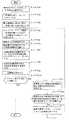
本装置の動作を説明する。図4は、X線CT装置100の実施形態1の動作の概略を示すフロー図である。
ステップS1では、造影剤が来ているかモニタする関心領域を設定する。これによって、例えば図4の(b)に示すような関心領域ROImが設定される。The operation of this apparatus will be described. FIG. 4 is a flowchart showing an outline of the operation of the first embodiment of the
In step S1, a region of interest for monitoring whether a contrast agent is coming is set. Thereby, for example, a region of interest ROIm as shown in FIG. 4B is set.
ステップS2では、一定時間おきに、モニタスキャンする。
モニタフェーズでは、図4の(a)に示すように一定周期△tmでコンベンショナルスキャン(アキシャルスキャン)を行ない、関心領域ROIm内の平均CT値が一定値以上になるのを待つ。この平均CT値が閾値を超えることで造影剤の到達がわかる。この時のコンベンショナルスキャンは1枚のシングルスキャンでも良いし、複数枚のマルチスキャンでも良い。In step S2, monitor scanning is performed at regular intervals.
In the monitor phase, as shown in FIG. 4A, a conventional scan (axial scan) is performed at a constant period Δtm, and the process waits for the average CT value in the region of interest ROIm to become a predetermined value or more. When this average CT value exceeds the threshold value, the arrival of the contrast agent is known. The conventional scan at this time may be one single scan or a plurality of multi-scans.
ステップS3では、ROI内のCT値が一定値に達した時を検出する。
ステップS4では、スキャンモードで、X線管・多列検出器からなるデータ収集系から投影データを収集するデータ収集する。X線管21と多列検出器24とを撮影対象の周りに回転させかつクレードル12をテーブル直線移動させながらテーブル直線移動位置zとビュー角度と検出器列番号jとチャネル番号iとで表わされる投影データD0(view,j,i)を収集する。すなわち、ヘリカルスキャンによりデータ収集を行う。なおこの時、投影データにはz軸方向の撮影テーブルのz座標として、多列検出器24およびX線管21からなるデータ収集系のz方向の中心位置での撮影テーブルのz座標情報Z(view)を付加する。このデータ収集処理については、図5〜図9を参照して後述する。In step S3, the time when the CT value in the ROI reaches a certain value is detected.
In step S4, data is collected in the scan mode to collect projection data from a data acquisition system consisting of an X-ray tube / multi-row detector. The table linear movement position z, the view angle, the detector row number j, and the channel number i are expressed by rotating the
図5の(a)に示すようにスキャンフェーズでは、一定周期△tsで可変ピッチヘリカルスキャン(variable pitchscan)による画像再構成を行なう。画像再構成の周期はスキャンの1回転の周期と同じでなくてもよい。この画像再構成では後述のマルチポジションモードで複数枚の断層像の再構成を行ない、どの位置の断層像まで関心領域ROIsの平均CT値が閾値を超えているかで造影剤の位置を判断する。なお、図5の(b)示すように設定された関心領域ROIsのx,y座標位置は、z軸方向の位置に依存させてもよい。 As shown in FIG. 5A, in the scan phase, image reconstruction is performed by a variable pitch helical scan at a constant period Δts. The period of image reconstruction may not be the same as the period of one scan. In this image reconstruction, a plurality of tomographic images are reconstructed in a multi-position mode, which will be described later, and the position of the contrast agent is determined depending on which tomographic image the average CT value of the region of interest ROIs exceeds the threshold value. Note that the x and y coordinate positions of the region of interest ROIs set as shown in FIG. 5B may depend on the position in the z-axis direction.
ステップS5では、図4のステップS5に示す通り投影データD0(view,j,i)に対して、図6のフロー図で示すように、前処理(オフセット補正(ステップS51)、対数変換(ステップS52)、X線線量補正(ステップS53)および感度補正(ステップS54)を行う。 In step S5, as shown in the flowchart of FIG. 6, the pre-processing (offset correction (step S51), logarithmic conversion (step S52), X-ray dose correction (step S53) and sensitivity correction (step S54) are performed.
ステップS6では、前処理した投影データD0(view,j,i)に対して、再構成関数重畳処理を行う。すなわち、フーリエ変換し、再構成関数を乗算し、逆フーリエ変換する。
ステップS7では、再構成関数重畳処理した投影データD0(view,j,i)に対して、3次元逆投影処理(マルチポジションモード)を行い、逆投影データD3(x,y)を求める。この3次元逆投影処理については、図21を参照して後述する。In step S6, reconstruction function superimposition processing is performed on the preprocessed projection data D0 (view, j, i). That is, the Fourier transform is performed, the reconstruction function is multiplied, and the inverse Fourier transform is performed.
In step S7, three-dimensional backprojection processing (multi-position mode) is performed on the projection data D0 (view, j, i) subjected to reconstruction function superimposition processing to obtain backprojection data D3 (x, y). This three-dimensional backprojection process will be described later with reference to FIG.
なお、マルチポジションモードとは複数のCT画像の時間相を備えることが出来るモードである。多列検出器を用いたコンベンショナルスキャン(アキシャルスキャン)またはヘリカルスキャンによりデータを収集すると共に、1回のアキシャルスキャンまたは1回転のヘリカルスキャンにより収集したデータからスライス位置が異なる複数の断層像を生成することができる。 The multi-position mode is a mode that can have a plurality of time phases of CT images. Collects data by conventional scan (axial scan) using a multi-row detector or helical scan, and generates multiple tomograms with different slice positions from data collected by one axial scan or one helical scan be able to.
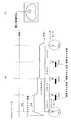
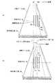
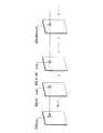
従来はヘリカルスキャンでは図7に示すように、P1の1枚の断層像しか再構成できなかった。 また、アキシャルスキャンでも従来は図8に示すように、8A, 7A, 6A, 5A, 4A, 3A, 2A, 1A, 1B, 2B, 3B, 4B, 5B, 6B, 7B, 8Bの多列検出器の列中心位置しか画像再構成ができなかった。 Conventionally, only one P1 tomographic image can be reconstructed by helical scanning as shown in FIG. Also in the axial scan, as shown in Fig. 8, the conventional multi-row detector of 8A, 7A, 6A, 5A, 4A, 3A, 2A, 1A, 1B, 2B, 3B, 4B, 5B, 6B, 7B, 8B Only the center position of the image can be reconstructed.
しかし、3次元画像再構成を用いたマルチポジションモードでは図8に示すように、ヘリカルスキャンではP1〜P4(あるいはもっと多く)の断層像が3次元画像再構成でき、アキシャルスキャンでも多列検出器の列中心の位置以外でも自由な位置に3次元画像再構成ができる。 However, in the multi-position mode using 3D image reconstruction, as shown in Fig. 8, the helical scan can reconstruct P1-P4 (or more) tomographic images and 3D images can be reconstructed even in the axial scan. 3D image reconstruction can be performed at any position other than the position of the column center.
このマルチポジションモードにより、3次元画像再構成された断層像の各々の関心領域ROIsにおいて、あらかじめ定められた造影された血流が来たかを判断する閾値より平均CT値が高ければ造影された血流が来たと判断できる。 With this multi-position mode, in each region of interest ROIs of the tomographic image reconstructed in the three-dimensional image, if the average CT value is higher than a predetermined threshold value for determining whether or not a contrasted blood flow has come, the contrasted blood It can be judged that the flow has come.
すなわち、図9に示すように、何スライス目まで造影された血流の最先端があるかがわかれば、その時刻と合わせて造影された血流の速度がわかる。データ収集系の中心座標からの距離Dbnがわかる。つまり中心からnスライス目に造影された血流の最先端があれば(nは1オリジン)その造影された血流の最造端のz座標Zbnと、データ収集系の中心座標Zsnは、 That is, as shown in FIG. 9, if it is known how many slices have the most advanced blood flow, the speed of the blood flow imaged at that time can be known. The distance Dbn from the center coordinate of the data collection system is known. In other words, if there is the most advanced blood flow contrasted at the nth slice from the center (n is 1 origin), the z-coordinate Zbn of the contrasted blood flow and the center coordinate Zsn of the data collection system are

となるため、可変ピッチヘリカルの速度調整量ΔVhnは、Therefore, the variable pitch helical speed adjustment amount ΔVhn is
となる。
ステップS8では、逆投影データD3(x,y)に対して後処理を行い、CT画像を得る。
図10は、データ収集処理(図3のステップS4)の詳細を示すフロー図である。It becomes.
In step S8, post-processing is performed on the backprojection data D3 (x, y) to obtain a CT image.
FIG. 10 is a flowchart showing details of the data collection process (step S4 in FIG. 3).
ステップS401では、コリメータをz≧0の所だけを開いておく。
ステップS402では、X線管21と多列検出器24とを撮影対象の周りに回転させる。
ステップS403では、クレードル12のテーブル直線移動をスタートさせる。In step S401, the collimator is opened only at a place where z ≧ 0.
In step S402, the
In step S403, the table linear movement of the cradle 12 is started.
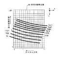
ステップS404では、クレードル12のテーブル直線移動速度を所定関数に基づいて加速し、それに合わせて速度/管電流が一定値になるように管電流を増加させる。所定関数が時間に対してリニアの場合を図11,図12に示し、所定関数が時間に対してノンリニアの場合を図13,図14に示す。X線データ収集系のz方向の中心位置がz=0に到達したらX線を出力する。またコリメータの開閉制御も行なう。 In step S404, the table linear movement speed of the cradle 12 is accelerated based on a predetermined function, and the tube current is increased so that the speed / tube current becomes a constant value accordingly. 11 and 12 show cases where the predetermined function is linear with respect to time, and FIGS. 13 and 14 show cases where the predetermined function is non-linear with respect to time. When the center position in the z direction of the X-ray data acquisition system reaches z = 0, X-rays are output. The collimator is also controlled for opening and closing.
この時のコリメータの開き具合を、
cw:コリメータ開閉幅
zce:コリメータ開閉のz座標最大値(+側)
zcs:コリメータ開閉のz座標最小値(−側)とすると、
cw=zce−zcsとなる。
zd:データ収集系の中心z座標
zs:ヘリカルスキャン開始時のz座標(zs=0)
ze:ヘリカルスキャン停止時のz座標とすると、
この時に、X線データ収集開始時にはzcs=zs=0となるように制御する。X線データ収集終了時には、zceは設定されたスライス厚のz座標+側、zcs=zeとなるように制御する。The degree of opening of the collimator at this time
cw: Collimator open / close width
zce: Maximum z-coordinate value for collimator opening / closing (+ side)
zcs: z coordinate minimum value (− side) for collimator opening and closing
cw = zce-zcs.
zd: Center z coordinate of the data collection system
zs: z coordinate at the start of helical scan (zs = 0)
ze: z coordinate at the time of helical scan stop
At this time, control is performed so that zcs = zs = 0 at the start of X-ray data collection. At the end of X-ray data collection, zce is controlled to be z coordinate + side of the set slice thickness, zcs = ze.
また、コリメータの開閉具合の測定は、図15に示すコリメータ位置検出チャネル(斜線部)で行なう。このチャネルの出力をz方向(列方向)に沿って見ると図16のようになる。この時の検出器出力信号の出ている幅、wa,wbwcを求めることにより、コリメータの開閉具合がわかる。つまり、テーブル装置10のz方向座標を求めるエンコーダによりカウントされたz方向の座標は制御コントローラ29にてz軸座標として算出され、スリップリング30を経由しDAS25に到達する。 The collimator opening / closing state is measured by the collimator position detection channel (shaded portion) shown in FIG. FIG. 16 shows the output of this channel when viewed along the z direction (column direction). By obtaining the width, wa, and wbwc of the detector output signal at this time, the open / close state of the collimator can be determined. That is, the z-direction coordinates counted by the encoder for obtaining the z-direction coordinates of the table device 10 are calculated as z-axis coordinates by the
また、DAS25ではコリメータ位置検出チャネルの出力から現在のコリメータ開閉具合を知ることができ、z座標から求められたコリメータ開閉目標値まで開閉するようにコリメータ23に指令を出せる。 Further, the
また、指令通りに動いたかのフィードバック制御はコリメータ位置検出チャネルの出力から求められるコリメータ開閉値とコリメータ開閉目標値との差を求めてフィードバック信号を作り、コリメータに指令を出しフィードバック制御を行う。 Further, the feedback control of whether or not the operation has been performed according to the command determines the difference between the collimator open / close value obtained from the output of the collimator position detection channel and the collimator open / close target value, creates a feedback signal, and issues a command to the collimator for feedback control.
ステップS405ではコリメータをz≧0の所だけを開いておく。つまり、zcs=zs=0になるようにコリメータを制御する。
ステップS406では、加速中の投影データD0(view,j,i)を収集する。In step S405, the collimator is opened only at a place where z ≧ 0. That is, the collimator is controlled so that zcs = zs = 0.
In step S406, acceleration projection data D0 (view, j, i) is collected.
ステップS407では、クレードル12のテーブル直線移動速度が図11や図13に示す所定速度Vcに達したらステップS408へ進み、所定速度Vcに達してなかったらステップS404に戻ってさらに加速する。 In step S407, if the table linear movement speed of the cradle 12 reaches the predetermined speed Vc shown in FIGS. 11 and 13, the process proceeds to step S408, and if it does not reach the predetermined speed Vc, the process returns to step S404 and further accelerates.
ステップS408では、クレードル12のテーブル直線移動速度を所定速度に維持した状態で定速の投影データD0(view,j,i)を収集する。
ステップS409では、クレードル12が図11や図13に示す定速終了位置に達したらステップS410へ進み、定速終了位置に達してなかったらステップS408に戻って定速の投影データ収集を継続する。In step S408, constant-speed projection data D0 (view, j, i) is collected with the table linear movement speed of the cradle 12 maintained at a predetermined speed.
In step S409, if the cradle 12 reaches the constant speed end position shown in FIGS. 11 and 13, the process proceeds to step S410. If the cradle 12 has not reached the constant speed end position, the process returns to step S408 and the constant-speed projection data collection is continued.
ステップS410では、クレードル12のテーブル直線移動速度を所定関数に基づいて減速し、それに合わせて管電流を減少させる。所定関数がリニアの場合を図11,図12に示し、所定関数がノンリニアの場合を図13,図14に示す。X線データ収集系のコリメータのz方向最大値側の座標zceがヘリカルスキャン停止時の座標 zeにかかり始めたら、zce= zeになるようにコリメータ開閉を制御し始める。X線データ収集系の中心座標、zd= zeになった時にX線出力を停止する。 In step S410, the table linear movement speed of the cradle 12 is decelerated based on a predetermined function, and the tube current is reduced accordingly. 11 and 12 show the case where the predetermined function is linear, and FIGS. 13 and 14 show the case where the predetermined function is non-linear. When the coordinate zce on the maximum side in the z direction of the collimator of the X-ray data collection system starts to be applied to the coordinate ze when the helical scan is stopped, the collimator opening / closing control is started so that zce = ze. X-ray output is stopped when the central coordinate of the X-ray data acquisition system, zd = ze.
ステップS411ではコリメータをz≧zeの所だけを開いておく。つまり、zce=zeになるようにコリメータを制御する。
ステップS412では、減速中の投影データD0(view,j,i)を収集する。In step S411, the collimator is opened only at a location where z ≧ ze. That is, the collimator is controlled so that zce = ze.
In step S412, projection data D0 (view, j, i) during deceleration is collected.
ステップS413では、クレードル15のテーブル直線移動速度が図11や図13に示す停止可能速度に達したらステップS414へ進み、停止可能速度に達してなかったらステップS410に戻ってさらに減速する。 In step S413, if the table linear movement speed of the cradle 15 reaches the stoppable speed shown in FIGS. 11 and 13, the process proceeds to step S414. If it does not reach the stoppable speed, the process returns to step S410 and further decelerates.
ステップS414では、クレードル15のテーブル直線移動を停止させる。
なお、図17〜図20に示すように、定速開始位置=定速終了位置に設定すれば、最も短いテーブル直線移動距離で投影データD0(view,j,i)を収集できる。In step S414, the table linear movement of the cradle 15 is stopped.
As shown in FIGS. 17 to 20, if the constant speed start position is set to the constant speed end position, the projection data D0 (view, j, i) can be collected with the shortest table linear movement distance.
図21は、3次元逆投影処理(図3のステップS7)の詳細を示すフロー図である。
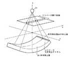
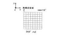
ステップS61では、CT画像の再構成に必要な全ビュー(すなわち、360度分のビュー又は「180度分+ファン角度分」のビュー)中の一つのビューに着目し、再構成領域Pの各画素に対応する投影データDrを抽出する。FIG. 21 is a flowchart showing details of the three-dimensional backprojection process (step S7 in FIG. 3).
In step S61, attention is paid to one view among all views necessary for CT image reconstruction (ie, a view for 360 degrees or a view for "180 degrees + fan angle"). Projection data Dr corresponding to the pixel is extracted.
図22に示すように、xy平面に平行な512×512画素の正方形の領域を再構成領域Pとし、y=0のx軸に平行な画素列L0,y=63の画素列L63,y=127の画素列L127,y=191の画素列L191,y=255の画素列L255,y=319の画素列L319,y=383の画素列L383,y=447の画素列L447,y=511の画素列L511を列にとると、これらの画素列L0〜L511をX線透過方向に多列X線検出器24の面に投影した図23に示す如きラインT0〜T511上の投影データを抽出すれば、それらが画素列L0〜L511の投影データDrとなる。 As shown in FIG. 22, a square region of 512 × 512 pixels parallel to the xy plane is set as a reconstruction region P, and pixel rows L0 and y = 63 are parallel to the x axis where y = 0, y = 63. 127 pixel row L127, y = 191 pixel row L191, y = 255 pixel row L255, y = 319 pixel row L319, y = 383 pixel row L383, y = 447 pixel row L447, y = 511 When the pixel column L511 is taken as a column, projection data on lines T0 to T511 as shown in FIG. 23 in which these pixel columns L0 to L511 are projected on the surface of the
X線透過方向は、X線管21のX線焦点と各画素と多列X線検出器24との幾何学的位置によって決まるが、投影データD0(z,view,j,i)のz座標が判っているため、加速・減速中の投影データD0(z,view,j,i)でもX線透過方向を正確に求めることが出来る。 The X-ray transmission direction is determined by the X-ray focal point of the
なお、例えば画素列L0をX線透過方向に多列X線検出器24の面に投影したラインT0のように、ラインの一部が多列X線検出器24の面外に出た場合は、対応する投影データDrを「0」にする。 For example, when a part of the line goes out of the plane of the
かくして、図24に示すように、再構成領域Pの各画素に対応する投影データDr(view,x,y)を抽出できる。
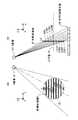
図21に戻り、ステップS62では、投影データDr(view,x,y)にコーンビーム再構成荷重係数を乗算し、図25に示す如き投影データD2(view,x,y)を作成する。Thus, as shown in FIG. 24, projection data Dr (view, x, y) corresponding to each pixel in the reconstruction area P can be extracted.
Returning to FIG. 21, in step S62, the projection data Dr (view, x, y) is multiplied by the cone beam reconstruction load coefficient to create projection data D2 (view, x, y) as shown in FIG.
ここで、コーンビーム再構成荷重係数は、X線管21の焦点から投影データDrに対応する多列X線検出器24の検出器列j,チャネルiまでの距離をr0とし、X線管21の焦点から投影データDrに対応する再構成領域P上の画素までの距離をr1とするとき、(r1/r0)2である。Here, the cone beam reconstruction load coefficient is defined as a distance from the focal point of the
ステップS63では、図26に示すように、予めクリアしておいた逆投影データD3(x,y)に、投影データD2(view,x,y)を画素対応に加算する。
ステップS64では、CT画像の再構成に必要な全ビュー(すなわち、360度分のビュー又は「180度分+ファン角度分」のビュー)について、ステップS61〜S63を繰り返し、図26に示すように、逆投影データD3(x,y)を得る。In step S63, as shown in FIG. 26, the projection data D2 (view, x, y) is added in correspondence with the pixels to the backprojection data D3 (x, y) that has been cleared in advance.
In step S64, steps S61 to S63 are repeated for all views necessary for CT image reconstruction (that is, views for 360 degrees or views for "180 degrees + fan angle"), as shown in FIG. , Back projection data D3 (x, y) is obtained.
なお、図27に示すように、再構成領域Pを円形の領域としてもよい。
以上のX線CT装置100によれば、テーブル直線移動速度が一定に維持されている間だけでなく、テーブル直線移動の加・減速中にも投影データを収集し、スキャン中の体軸方向(以下z軸という)の座標情報を各ビューデータもしくは数ビューデータに一回付加し、収集した投影データをZ軸座標、情報とともに画像再構成に利用する。このため、全体のテーブル直線移動距離のうちの加・減速のためのテーブル直線移動距離分も画像再構成に利用できるようになる。As shown in FIG. 27, the reconstruction area P may be a circular area.
According to the
なお、3次元画像再構成法は、従来公知のフェルドカンプ法による3次元画像再構成法でもよい。さらに、特願2002−066420号、特願2002−147061号、特願2002−147231号、特願2002−235561号、特願2002−235662号、特願2002−267833号、特願2002−322756号および特願2002−338947号で提案されている3次元画像再構成法を用いてもよい。また、3次元画像再構成でなく、従来の2次元画像再構成でも同様の効果は出せる。 The three-dimensional image reconstruction method may be a three-dimensional image reconstruction method by a conventionally known Feldkamp method. Furthermore, Japanese Patent Application No. 2002-066420, Japanese Patent Application No. 2002-147061, Japanese Patent Application No. 2002-147231, Japanese Patent Application No. 2002-235561, Japanese Patent Application No. 2002-235663, Japanese Patent Application No. 2002-267833, Japanese Patent Application No. 2002-322756 The three-dimensional image reconstruction method proposed in Japanese Patent Application No. 2002-338947 may also be used. The same effect can be obtained not only by the three-dimensional image reconstruction but also by the conventional two-dimensional image reconstruction.
なお、本実施例では可変ピッチヘリカルの開始と停止時にシャッタモードを用いているが、用いなくても同様の効果は出せる。
また、本実施例では可変ピッチヘリカル中における断層像の画像再構成の時間間隔、z方向間隔が一定である例を示しているが、必ずしも時間的にも空間的にも一定である必要はない。In this embodiment, the shutter mode is used at the start and stop of the variable pitch helical, but the same effect can be obtained without using the shutter mode.
In this embodiment, an example is shown in which the time interval and the z-direction interval of tomographic image reconstruction in a variable pitch helical are constant, but it is not necessarily constant in terms of time and space. .
また、本実施例ではスキャンフェーズ用関心領域ROIsはz方向に同一位置であるように書かれているが、図28に示すように、関心領域ROIsiの位置(xsi,ysi)および、サイズ(lxi,lyi)は着目している血管に沿ってz方向により変化してかまわない。 In the present embodiment, the region of interest ROIs for scan phase is written to be at the same position in the z direction. However, as shown in FIG. 28, the position (xsi, ysi) and size (lxi) of the region of interest ROIsi are written. , lyi) may change in the z direction along the blood vessel of interest.
次に図29、図30に実施形態2を示す。この場合は実施形態における造影された血流の最先端部の追跡精度を上げて、常にデータ収集系のz方向の中心座標が造影された血流の最先端近辺に来るように制御する。 Next, FIG. 29 and FIG. 30 show the second embodiment. In this case, the tracking accuracy of the most advanced portion of the contrasted blood flow in the embodiment is increased, and control is performed so that the center coordinate in the z direction of the data acquisition system is always near the leading edge of the contrasted blood flow.
図29は実施形態2における造影された血流の最先端が常にデータ収集系のz方向の中心に来るように制御される例の説明図である。図30は実施形態2における造影された血流の断層像と造影されていない断層像の同一部位、場所の差分画像から造影された血流のみが抽出される説明図である。このようにして1回の可変ピッチヘリカルスキャンにより、造影された血流のみを抽出して画像化することが可能である。 FIG. 29 is an explanatory diagram of an example in which control is performed so that the leading edge of the contrasted blood flow in the second embodiment is always at the center in the z direction of the data acquisition system. FIG. 30 is an explanatory diagram in which only the contrasted blood flow is extracted from the difference image of the same site and location of the contrasted tomographic image and the non-contrast tomographic image in the second embodiment. In this way, it is possible to extract and image only the contrasted blood flow by one variable pitch helical scan.
1 操作コンソール
2 入力装置
3 中央処理装置
5 データ収集バッファ
6 CRT
7 記憶装置
10 撮影テーブル
12 クレードル
15 回転部
20 走査ガントリ
21 X線管
22 X線コントローラ
23 コリメータ
24 多列検出器
25 DAS(データ収集装置)
26 回転部コントローラ
27 制御コントローラ
28 スリップリング
30 X線線量比較検出器
dP 検出器面
P 再構成領域
PP 投影面
Va 加速時のテーブル直線移動速度
Vb 減速時のテーブル直線移動速度
Vc 定速時のテーブル直線移動速度1
7 Storage Device 10 Imaging Table 12 Cradle 15 Rotating Unit 20
26 Rotating part controller 27 Control controller 28 Slip ring 30 X-ray dose comparison detector dP Detector surface P Reconstruction area PP Projection surface Va Table linear movement speed Vb during acceleration Table linear movement speed Vc during deceleration Table at constant speed Linear moving speed
Claims (9)
Translated fromJapanese前記X線CT装置は、前記ヘリカルスキャンにおける前記多列X線検出器の中心のz軸方向における位置情報を取得する手段をさらに有し、
前記制御手段は、前記被検体内の造影剤の動きに追従しながらヘリカルスキャンを行うように制御するものであって、前記ヘリカルスキャンによって得られたz軸方向における位置を異にする同じ時間相の複数の断層像の中から造影剤の先頭が到達している断層像を、あらかじめ設定された関心領域のCT値に基づいて、異なる複数の時間相について検出し、前記位置情報に基づく前記複数の異なる時間相における前記造影剤の先頭が到達している断層像の位置を用いて前記テーブルの移動速度調整量を予測し、前記移動速度調整量に基づいて前記進行中のヘリカルスキャンにおけるテーブルの直線移動の速度を制御する、
ことを特徴とするX線CT装置。An X-ray source, amulti-row X-ray detector placed on atable and arranged to face the X-ray source across a subject intowhich a contrast medium is injected, and thetable linearly extending in the z-axis direction An X-ray CT apparatus having image reconstruction means for reconstructing atomographic image based on projection data obtained byperforming helical scan ona subjectwhile moving and subjecting the X-ray detector, and control means for controlling helical scan. And
The X-ray CT apparatus further includes means for acquiring position information in the z-axis direction of the center of the multi-row X-ray detector in the helical scan,
Said control means,saidbeen made to control to perform a helical scanwhile followingthe movement of the contrast agent in thesubject, the same time phase different in position in the z-axis direction obtained by the helical scan A plurality of tomographic images in which the top of the contrast agent has arrived are detected for a plurality of different time phases based on a preset CT value of the region of interest, and the plurality of tomographic images based on the position information Predicting the moving speed adjustment amount of the table using the position of the tomographic image at which the head of the contrast agent has reached in different time phases of the table, and based on the moving speed adjustment amount, the table of the table in the ongoing helical scan Control the speed oflinear movement ,
An X-ray CT apparatus characterized by that.
ことを特徴とする請求項1ないし請求項3のうちのいずれか1つに記載のX線CT装置。The region of interest is set independently for each tomographic image in the plurality of tomographic images.
The X-ray CT apparatus according toany one of claims 1 to 3, wherein the X-ray CT apparatus is characterized by the above.
ことを特徴とする請求項1ないし請求項4のうちのいずれか1つに記載のX線CT装置。The control means continuously changes the speedof linear movement of thetable during scanning.
The X-ray CT apparatus according to any one ofclaims 1 to 4 , wherein the X-ray CT apparatus is characterized by the above.
ことを特徴とする請求項1ないし請求項5のうちのいずれか1つに記載のX線CT装置。An interval inthe linear movement direction of thetable of the plurality of tomographic images is constant.
The X-ray CT apparatus according to any one ofclaims 1 to 5 , wherein
ことを特徴とする請求項1ないし請求項5のうちのいずれか1つに記載のX線CT装置。The interval inthe linear movement direction of thetable of the plurality of tomographic images is an indefinite interval.
The X-ray CT apparatus according to any one ofclaims 1 to 5 , wherein
ことを特徴とする請求項1ないし請求項7のうちのいずれか1つに記載のX線CT装置。The control means performs a monitoring scan for detecting a change in the CT value of the region of interest prior to the start of the helical scan.
The X-ray CT apparatus according toclaim 1 , wherein the X-ray CT apparatus is any one ofclaims 1 to 7 .
前記画像再構成手段は前記X線検出器の中心位置に関してヘリカルスキャン進行方向における前半分および後半分を通じてそれぞれ得られた投影データに基づいてそれぞれ画像再構成を行うとともに同じ場所におけるそれらの画像の差分画像を求める、
ことを特徴とする請求項1ないし請求項8のうちのいずれか1つに記載のX線CT装置。The control means controls the helical scan so that the center position of the X-ray detector in the traveling direction of the helical scan corresponds to the position of the tip of the contrast agent;
The image reconstruction means performs image reconstruction on the basis of projection data obtained through the front half and the rear half in the helical scan traveling direction with respect to the center position of the X-ray detector, and the differencebetween the images at thesame place Ask for an image,
The X-ray CT apparatus according to any one ofclaims 1 to 8 , wherein the X-ray CT apparatus is characterized by the above.
Priority Applications (5)
| Application Number | Priority Date | Filing Date | Title |
|---|---|---|---|
| JP2004235900AJP4319109B2 (en) | 2004-08-13 | 2004-08-13 | Scan control method and X-ray CT apparatus |
| US11/199,416US7313216B2 (en) | 2004-08-13 | 2005-08-08 | Scan control method and X-ray CT apparatus |
| KR1020050074326AKR100654495B1 (en) | 2004-08-13 | 2005-08-12 | Scan control method and x-ray ct apparatus |
| CN2005100924299ACN1732851B (en) | 2004-08-13 | 2005-08-12 | Scan control method and x-ray CT apparatus |
| DE102005038561ADE102005038561A1 (en) | 2004-08-13 | 2005-08-12 | Scan control method and X-ray CT apparatus |
Applications Claiming Priority (1)
| Application Number | Priority Date | Filing Date | Title |
|---|---|---|---|
| JP2004235900AJP4319109B2 (en) | 2004-08-13 | 2004-08-13 | Scan control method and X-ray CT apparatus |
Publications (2)
| Publication Number | Publication Date |
|---|---|
| JP2006051234A JP2006051234A (en) | 2006-02-23 |
| JP4319109B2true JP4319109B2 (en) | 2009-08-26 |
Family
ID=35721775
Family Applications (1)
| Application Number | Title | Priority Date | Filing Date |
|---|---|---|---|
| JP2004235900AExpired - Fee RelatedJP4319109B2 (en) | 2004-08-13 | 2004-08-13 | Scan control method and X-ray CT apparatus |
Country Status (5)
| Country | Link |
|---|---|
| US (1) | US7313216B2 (en) |
| JP (1) | JP4319109B2 (en) |
| KR (1) | KR100654495B1 (en) |
| CN (1) | CN1732851B (en) |
| DE (1) | DE102005038561A1 (en) |
Families Citing this family (44)
| Publication number | Priority date | Publication date | Assignee | Title |
|---|---|---|---|---|
| EP1430835B1 (en)* | 2002-12-17 | 2011-11-16 | Kabushiki Kaisha Toshiba | System for peripheral X-ray angiography |
| JP2005177203A (en)* | 2003-12-22 | 2005-07-07 | Ge Medical Systems Global Technology Co Llc | Ct image forming method at plurality of positions, and x-ray ct device |
| DE102004059663A1 (en)* | 2004-12-10 | 2006-06-29 | Siemens Ag | Method for multidimensional imaging involves multi-row computer tomographs for scanning patient whereby scan speed is adjusted according to the propagation speed of contrast agent in scanning direction |
| JP2007000406A (en)* | 2005-06-24 | 2007-01-11 | Ge Medical Systems Global Technology Co Llc | X-ray ct method and x-ray ct apparatus |
| JP4509903B2 (en)* | 2005-09-27 | 2010-07-21 | ジーイー・メディカル・システムズ・グローバル・テクノロジー・カンパニー・エルエルシー | X-ray CT system |
| US7242749B2 (en)* | 2005-11-15 | 2007-07-10 | General Electric Company | Methods and systems for dynamic pitch helical scanning |
| JP2007236662A (en)* | 2006-03-09 | 2007-09-20 | Ge Medical Systems Global Technology Co Llc | X-ray ct system, its x-ray ct image reconstitution method and x-ray ct image photographing method |
| US7885374B2 (en)* | 2006-03-15 | 2011-02-08 | Kabushiki Kaisha Toshiba | X-ray CT apparatus, a method for changing the helical pitch, an image reconstruction processing apparatus, an image reconstruction processing method, and an image reconstruction processing program |
| JP5165903B2 (en)* | 2006-03-15 | 2013-03-21 | 株式会社東芝 | X-ray CT apparatus, helical pitch changing method |
| CN101059455B (en) | 2006-04-21 | 2011-06-08 | Ge医疗系统环球技术有限公司 | X ray detection device and X ray imaging device |
| JP2007289297A (en)* | 2006-04-23 | 2007-11-08 | Ge Medical Systems Global Technology Co Llc | X-ray ct apparatus |
| JP2008036275A (en)* | 2006-08-09 | 2008-02-21 | Toshiba Corp | X-ray CT system |
| US7983385B2 (en)* | 2006-09-29 | 2011-07-19 | Koninklijke Philips Electronics N.V. | Fly-by scanning |
| JP4901448B2 (en)* | 2006-12-18 | 2012-03-21 | ジーイー・メディカル・システムズ・グローバル・テクノロジー・カンパニー・エルエルシー | X-ray CT system |
| JP4823050B2 (en)* | 2006-12-18 | 2011-11-24 | ジーイー・メディカル・システムズ・グローバル・テクノロジー・カンパニー・エルエルシー | X-ray CT system |
| DE102007021023A1 (en) | 2007-05-04 | 2008-11-13 | Siemens Ag | Imaging method for the variable-pitch spiral CT and CT apparatus for performing the method |
| JP5269358B2 (en)* | 2007-07-18 | 2013-08-21 | 株式会社東芝 | X-ray CT system |
| DE102007034986B4 (en)* | 2007-07-26 | 2017-06-22 | Siemens Healthcare Gmbh | A method and tomography apparatus for scanning a contrasted patient |
| JP2009056108A (en)* | 2007-08-31 | 2009-03-19 | Toshiba Corp | X-ray computed tomography apparatus and method |
| US8090171B2 (en)* | 2007-10-19 | 2012-01-03 | Siemens Medical Solutions Usa, Inc. | Image data subtraction system suitable for use in angiography |
| JP5260036B2 (en)* | 2007-12-17 | 2013-08-14 | ジーイー・メディカル・システムズ・グローバル・テクノロジー・カンパニー・エルエルシー | X-ray CT system |
| JP5085305B2 (en)* | 2007-12-21 | 2012-11-28 | ジーイー・メディカル・システムズ・グローバル・テクノロジー・カンパニー・エルエルシー | X-ray CT system |
| EP2279494B1 (en)* | 2008-05-21 | 2016-11-02 | Koninklijke Philips N.V. | Dynamic adjustable source collimation during fly-by scanning |
| US20090310740A1 (en)* | 2008-06-16 | 2009-12-17 | General Electric Company | Computed tomography method and system |
| JP2010022708A (en)* | 2008-07-23 | 2010-02-04 | Toshiba Corp | X-ray ct apparatus |
| JP2010082428A (en)* | 2008-09-04 | 2010-04-15 | Toshiba Corp | X-ray computer tomography apparatus |
| DE102008062469A1 (en)* | 2008-12-18 | 2010-08-12 | Siemens Aktiengesellschaft | Patient scanning method for e.g. therapeutic purposes, involves determining updated position of image window in subsequent layer images, and arranging contrasting vessel in center in image window of subsequent layer images |
| US7881426B2 (en)* | 2009-02-26 | 2011-02-01 | Morpho Detection, Inc. | Method and system for performing a scan of an object |
| CN103379860B (en)* | 2011-02-18 | 2016-08-17 | 皇家飞利浦有限公司 | Imaging system subject support motion algorithm |
| US9521981B2 (en)* | 2012-04-11 | 2016-12-20 | Toshiba Medical Systems Corporation | X-ray CT system |
| US9198626B2 (en) | 2012-06-22 | 2015-12-01 | University Of Utah Research Foundation | Dynamic power control of computed tomography radiation source |
| US9259191B2 (en) | 2012-06-22 | 2016-02-16 | University Of Utah Research Foundation | Dynamic collimation for computed tomography |
| US9125572B2 (en) | 2012-06-22 | 2015-09-08 | University Of Utah Research Foundation | Grated collimation system for computed tomography |
| US9332946B2 (en)* | 2012-06-22 | 2016-05-10 | University Of Utah Research Foundation | Adaptive control of sampling frequency for computed tomography |
| DE102012214472B4 (en)* | 2012-08-14 | 2020-10-01 | Siemens Healthcare Gmbh | Method for determining dual-energy image data sets and an X-ray device for this purpose |
| CN105873518A (en)* | 2014-01-15 | 2016-08-17 | 株式会社日立制作所 | X-ray CT device and contrast imaging method |
| KR101609932B1 (en)* | 2014-07-02 | 2016-04-06 | (의료)길의료재단 | Curved movable beam stop array and CBCT comprising thereof |
| WO2017042280A1 (en)* | 2015-09-09 | 2017-03-16 | Technische Universiteit Eindhoven | Imaging of dispersion and velocity of contrast agents |
| US10383590B2 (en)* | 2015-09-28 | 2019-08-20 | General Electric Company | Methods and systems for adaptive scan control |
| CN111615364B (en) | 2018-01-19 | 2025-02-21 | 皇家飞利浦有限公司 | Adjustment of scanning parameters during contrast-enhanced scanning |
| KR102255289B1 (en) | 2019-05-23 | 2021-05-21 | 신한대학교 산학협력단 | Control method for bolus tracking CT |
| KR20200134654A (en) | 2019-05-23 | 2020-12-02 | 신한대학교 산학협력단 | Control method for bolus tracking CT |
| CN110473271B (en)* | 2019-08-20 | 2022-12-06 | 上海联影医疗科技股份有限公司 | Image data processing method, system, device and storage medium |
| EP4238500A1 (en)* | 2022-03-02 | 2023-09-06 | Koninklijke Philips N.V. | Measurement of blood flow parameters |
Family Cites Families (21)
| Publication number | Priority date | Publication date | Assignee | Title |
|---|---|---|---|---|
| DE4218321A1 (en)* | 1991-12-09 | 1993-06-17 | Siemens Ag | DIAGNOSTIC SYSTEM |
| US5412562A (en)* | 1992-04-02 | 1995-05-02 | Kabushiki Kaisha Toshiba | Computerized tomographic imaging method and system for acquiring CT image data by helical dynamic scanning |
| DE4220282A1 (en)* | 1992-06-20 | 1993-12-23 | Philips Patentverwaltung | Peripheral angiography procedure and arrangement for performing the procedure |
| US5594772A (en)* | 1993-11-26 | 1997-01-14 | Kabushiki Kaisha Toshiba | Computer tomography apparatus |
| US5684855A (en) | 1995-02-16 | 1997-11-04 | Kabushiki Kaisha Toshiba | X-ray CT scanner |
| US6023494A (en) | 1996-12-19 | 2000-02-08 | General Electric Company | Methods and apparatus for modifying slice thickness during a helical scan |
| US5864598A (en) | 1997-04-21 | 1999-01-26 | General Electric Company | Methods and apparatus for scanning an object in a computed tomography system |
| JP2001187046A (en)* | 1999-12-27 | 2001-07-10 | Ge Medical Systems Global Technology Co Llc | Multi-slice x-ray ct device and method for controlling the same |
| US6535821B2 (en)* | 2000-02-11 | 2003-03-18 | University Of Iowa Research Foundation | System and method of bolus-chasing angiography with adaptive real-time computed tomography (CT) |
| FR2818428A1 (en) | 2000-12-19 | 2002-06-21 | Ge Med Sys Global Tech Co Llc | Adjustable collimator for medical X-ray use has four shutters that can be moved independently, using stepper motors, to create a rectangular aperture of any size |
| US6990170B2 (en) | 2001-08-09 | 2006-01-24 | Kabushiki Kaisha Toshiba | X-ray computed tomographic imaging apparatus |
| JP4939702B2 (en) | 2001-08-09 | 2012-05-30 | 株式会社東芝 | X-ray CT system |
| JP2003159244A (en) | 2001-09-17 | 2003-06-03 | Ge Medical Systems Global Technology Co Llc | Image reconstruction method and x-ray ct apparatus |
| US7085343B2 (en) | 2001-10-18 | 2006-08-01 | Kabushiki Kaisha Toshiba | X-ray computed tomography apparatus |
| JP4176987B2 (en) | 2001-11-27 | 2008-11-05 | 株式会社東芝 | X-ray CT system |
| US7103134B2 (en)* | 2001-12-28 | 2006-09-05 | Kabushiki Kaisha Toshiba | Computed tomography apparatus |
| JP4106251B2 (en) | 2002-03-12 | 2008-06-25 | ジーイー・メディカル・システムズ・グローバル・テクノロジー・カンパニー・エルエルシー | Three-dimensional backprojection method and X-ray CT apparatus |
| JP4363618B2 (en) | 2002-05-22 | 2009-11-11 | ジーイー・メディカル・システムズ・グローバル・テクノロジー・カンパニー・エルエルシー | X-ray CT image reconstruction calculation method and X-ray CT apparatus |
| JP3950782B2 (en) | 2002-05-22 | 2007-08-01 | ジーイー・メディカル・システムズ・グローバル・テクノロジー・カンパニー・エルエルシー | Three-dimensional backprojection method and X-ray CT apparatus |
| JP4030827B2 (en) | 2002-08-13 | 2008-01-09 | ジーイー・メディカル・システムズ・グローバル・テクノロジー・カンパニー・エルエルシー | Projection data creation method, pixel data creation method, and multi-detector X-ray CT apparatus |
| JP2005160784A (en) | 2003-12-03 | 2005-06-23 | Hitachi Medical Corp | X-ray ct apparatus |
- 2004
- 2004-08-13JPJP2004235900Apatent/JP4319109B2/ennot_activeExpired - Fee Related
- 2005
- 2005-08-08USUS11/199,416patent/US7313216B2/ennot_activeExpired - Fee Related
- 2005-08-12CNCN2005100924299Apatent/CN1732851B/ennot_activeExpired - Fee Related
- 2005-08-12KRKR1020050074326Apatent/KR100654495B1/ennot_activeExpired - Fee Related
- 2005-08-12DEDE102005038561Apatent/DE102005038561A1/ennot_activeWithdrawn
Also Published As
| Publication number | Publication date |
|---|---|
| KR20060050447A (en) | 2006-05-19 |
| CN1732851B (en) | 2011-08-17 |
| US20060034419A1 (en) | 2006-02-16 |
| JP2006051234A (en) | 2006-02-23 |
| DE102005038561A1 (en) | 2006-02-23 |
| KR100654495B1 (en) | 2006-12-06 |
| US7313216B2 (en) | 2007-12-25 |
| CN1732851A (en) | 2006-02-15 |
Similar Documents
| Publication | Publication Date | Title |
|---|---|---|
| JP4319109B2 (en) | Scan control method and X-ray CT apparatus | |
| JP2006051233A (en) | Collimator control method and x-ray ct apparatus | |
| JP4630440B2 (en) | Method and apparatus for cardiac calcification counting based on scout images | |
| US7912175B2 (en) | X-ray CT apparatus and X-ray CT scanning method | |
| JP2007236662A (en) | X-ray ct system, its x-ray ct image reconstitution method and x-ray ct image photographing method | |
| US7706500B2 (en) | X-ray CT apparatus | |
| JP4611225B2 (en) | X-ray CT system | |
| US20080075225A1 (en) | Method for recording images of a definable region of an examination object using a computed tomography facility | |
| JP2002531199A (en) | Method and apparatus for calcification leveling | |
| JP2007181623A (en) | X-ray ct apparatus | |
| KR20070057055A (en) | X-ray CT device and its control method | |
| US20050008116A1 (en) | X-ray CT imaging method and x-ray CT system | |
| US20170281101A1 (en) | X-ray image forming device | |
| US7283607B2 (en) | Continuously operating tomography apparatus and method for the operation thereof | |
| JP4920256B2 (en) | X-ray CT system | |
| US20050094761A1 (en) | X-ray CT imaging method and X-ray CT apparatus | |
| US10123763B2 (en) | X-ray CT system | |
| US7164746B2 (en) | X-ray CT apparatus and imaging method | |
| JP2009000209A (en) | Method of controlling medical diagnostic imaging apparatus and cradle driving device | |
| JP6068027B2 (en) | X-ray CT system | |
| JP4901448B2 (en) | X-ray CT system | |
| JP4339202B2 (en) | X-ray CT system | |
| JP5378030B2 (en) | X-ray CT system | |
| JP2007319397A (en) | X-ray ct apparatus | |
| JP2005287984A (en) | X-ray CT system |
Legal Events
| Date | Code | Title | Description |
|---|---|---|---|
| A977 | Report on retrieval | Free format text:JAPANESE INTERMEDIATE CODE: A971007 Effective date:20080908 | |
| A131 | Notification of reasons for refusal | Free format text:JAPANESE INTERMEDIATE CODE: A131 Effective date:20080916 | |
| A521 | Request for written amendment filed | Free format text:JAPANESE INTERMEDIATE CODE: A523 Effective date:20081212 | |
| TRDD | Decision of grant or rejection written | ||
| A01 | Written decision to grant a patent or to grant a registration (utility model) | Free format text:JAPANESE INTERMEDIATE CODE: A01 Effective date:20090428 | |
| A01 | Written decision to grant a patent or to grant a registration (utility model) | Free format text:JAPANESE INTERMEDIATE CODE: A01 | |
| A61 | First payment of annual fees (during grant procedure) | Free format text:JAPANESE INTERMEDIATE CODE: A61 Effective date:20090527 | |
| FPAY | Renewal fee payment (event date is renewal date of database) | Free format text:PAYMENT UNTIL: 20120605 Year of fee payment:3 | |
| R150 | Certificate of patent or registration of utility model | Ref document number:4319109 Country of ref document:JP Free format text:JAPANESE INTERMEDIATE CODE: R150 | |
| FPAY | Renewal fee payment (event date is renewal date of database) | Free format text:PAYMENT UNTIL: 20120605 Year of fee payment:3 | |
| FPAY | Renewal fee payment (event date is renewal date of database) | Free format text:PAYMENT UNTIL: 20120605 Year of fee payment:3 | |
| FPAY | Renewal fee payment (event date is renewal date of database) | Free format text:PAYMENT UNTIL: 20130605 Year of fee payment:4 | |
| R250 | Receipt of annual fees | Free format text:JAPANESE INTERMEDIATE CODE: R250 | |
| FPAY | Renewal fee payment (event date is renewal date of database) | Free format text:PAYMENT UNTIL: 20130605 Year of fee payment:4 | |
| FPAY | Renewal fee payment (event date is renewal date of database) | Free format text:PAYMENT UNTIL: 20130605 Year of fee payment:4 | |
| R250 | Receipt of annual fees | Free format text:JAPANESE INTERMEDIATE CODE: R250 | |
| R250 | Receipt of annual fees | Free format text:JAPANESE INTERMEDIATE CODE: R250 | |
| R250 | Receipt of annual fees | Free format text:JAPANESE INTERMEDIATE CODE: R250 | |
| R250 | Receipt of annual fees | Free format text:JAPANESE INTERMEDIATE CODE: R250 | |
| R250 | Receipt of annual fees | Free format text:JAPANESE INTERMEDIATE CODE: R250 | |
| R250 | Receipt of annual fees | Free format text:JAPANESE INTERMEDIATE CODE: R250 | |
| R250 | Receipt of annual fees | Free format text:JAPANESE INTERMEDIATE CODE: R250 | |
| R250 | Receipt of annual fees | Free format text:JAPANESE INTERMEDIATE CODE: R250 | |
| R250 | Receipt of annual fees | Free format text:JAPANESE INTERMEDIATE CODE: R250 | |
| R250 | Receipt of annual fees | Free format text:JAPANESE INTERMEDIATE CODE: R250 | |
| R250 | Receipt of annual fees | Free format text:JAPANESE INTERMEDIATE CODE: R250 | |
| LAPS | Cancellation because of no payment of annual fees |