JP4318565B2 - Photo vending machine, photo vending machine control method, and photo vending machine control program - Google Patents
Photo vending machine, photo vending machine control method, and photo vending machine control programDownload PDFInfo
- Publication number
- JP4318565B2 JP4318565B2JP2004049905AJP2004049905AJP4318565B2JP 4318565 B2JP4318565 B2JP 4318565B2JP 2004049905 AJP2004049905 AJP 2004049905AJP 2004049905 AJP2004049905 AJP 2004049905AJP 4318565 B2JP4318565 B2JP 4318565B2
- Authority
- JP
- Japan
- Prior art keywords
- illumination
- unit
- photographing
- subject
- vending machine
- Prior art date
- Legal status (The legal status is an assumption and is not a legal conclusion. Google has not performed a legal analysis and makes no representation as to the accuracy of the status listed.)
- Expired - Lifetime
Links
Images


Landscapes
- Studio Devices (AREA)
- Cameras Adapted For Combination With Other Photographic Or Optical Apparatuses (AREA)
Description
Translated fromJapaneseこの発明は写真自動販売機、写真自動販売機の制御方法、および写真自動販売機の制御プログラムに関し、特に、ユーザの所望する美しい写真を提供することのできる写真自動販売機、写真自動販売機の制御方法、および写真自動販売機の制御プログラムに関する。 The present invention relates to a photo vending machine, a control method for a photo vending machine, and a control program for a photo vending machine, and more particularly to a photo vending machine and a photo vending machine capable of providing a beautiful photo desired by a user. The present invention relates to a control method and a control program for a photo vending machine.
近年、ゲームセンター等の遊戯を提供する店舗において、写真を撮影してシールプリント等にする写真自動販売機が数多く設置されている。このような写真自動販売機には、一般に、利用者である被写体をカメラで撮影し、その撮影画像をタブレットディスプレイなどに表示して付属のタッチペンで文字や図形などを入力する、いわゆる落書きやお絵描きといわれている編集機能があるものが一般的になっている。そして、このような編集入力された画像は撮影画像と合成され、その合成画像がプリンタで印刷されて利用者に提供される。 2. Description of the Related Art In recent years, many photo vending machines that take pictures and make sticker prints or the like have been installed in stores that provide games such as game centers. In such a photo vending machine, generally, a photograph of a subject that is a user is photographed with a camera, the photographed image is displayed on a tablet display, etc., and characters and figures are input with the attached touch pen. Those that have an editing function called painting are becoming common. The edited and input image is combined with the captured image, and the combined image is printed by a printer and provided to the user.
このような写真自動販売機は、撮影したときのできあがり写真の美しさや被写体の写り具合のよさに人気度が影響されるため、撮影時に美しい写り具合を実現するために様々な工夫がなされている。中でも、撮影時に被写体を照明する照明装置などは、その光量や配置する位置に応じて被写体の写り具合が異なる。そのため、現在の写真自動販売機において、照明方法は重要なファクタとなり得る。 Such photo vending machines are affected by the beauty of the photo that is taken when the photo is taken and the quality of the subject, so various efforts have been made to achieve a beautiful look at the time of shooting. Yes. Among them, the lighting device that illuminates the subject at the time of shooting differs in how the subject is projected depending on the amount of light and the position of the illuminating device. Therefore, the lighting method can be an important factor in current photo vending machines.
特許文献1〜4には、被写体を効果的に照明するための写真シール自動販売方法が開示されている。 Patent Documents 1 to 4 disclose photo sticker vending methods for effectively illuminating a subject.
これらの特許文献にも開示されているように、写真自動販売機の写り具合の質は照明などの工夫により向上しており、できあがりの写真を美しく保つような様々な照明が実現されている。
しかしながら、利用者によって好みの写り具合が異なるため、単一の照明バリエーションではすべての利用者を満足させることができないという問題があった。 However, there is a problem that not all users can be satisfied with a single illumination variation because the user's preferred image quality varies.
また、最近では、光の質によって固くシャープな写り具合や柔らかいふんわりとしたソフトな写り具合など、様々な照明バリエーションが写真自動販売機において実現され得るが、1つの写真自動販売機で複数の照明バリエーションを用意してユーザの所望に近い画質を実現するためには、ストロボが多く必要となって、コストアップや、装置の大型化、複雑化につながるという問題があった。 Recently, various lighting variations can be realized in photo vending machines, such as hard and sharp images depending on the light quality, and soft and soft images. In order to prepare variations and realize image quality close to the user's desire, a large number of strobes are required, leading to problems of increased cost, increased size and complexity of the apparatus.
また、被写体を正面から撮影するときに、顔の写り具合と髪の毛の写り具合とは異なる方がより美しい画像が得られるが、被写体の正面から照射するフラッシュの光で顔と髪の毛との異なる写り具合を実現することは困難であり、一様な写り具合となる照明しか行なうことができないという問題があった。さらに、照明手法によっては、一部分だけはソフトな光質で写した方が美しく撮影できるなど、被写体に照射する部位によって、最適な光質は異なるという問題があった。 Also, when shooting the subject from the front, a more beautiful image will be obtained if the appearance of the face is different from the appearance of the hair, but the image of the face and hair will be different due to the flash light emitted from the front of the subject. It is difficult to realize the condition, and there is a problem that only illumination with a uniform image condition can be performed. In addition, depending on the illumination method, there is a problem that the optimum light quality differs depending on the part irradiated on the subject, such as when a part of the image is captured with a soft light quality so that it can be taken beautifully.
本発明はこれらの問題に鑑みてなされたものであって、低コストで複数の光質の照明バリエーションと被写体の部位ごとに美しく撮影するための照明とを実現することのできる写真自動販売機、写真自動販売機の制御方法、および写真自動販売機の制御プログラムを提供することを目的とする。 The present invention has been made in view of these problems, and is a photo vending machine capable of realizing a plurality of illumination variations of light quality and illumination for beautiful photographing for each part of a subject at low cost, It is an object of the present invention to provide a control method for a photo vending machine and a control program for the photo vending machine.
上記目的を達成するために、本発明のある局面に従うと、写真自動販売機は、被写体を撮影する撮影手段と、被写体を照明する照明手段とを備え、照明手段は、撮影手段よりも上方に設置されて、撮影手段に相対した被写体を撮影手段側から撮影手段の撮影方向と略平行に照明する第1の照明手段を含み、第1の照明手段は、箱型の筐体と、箱型の筐体内部の光源と、光源より発光された光を被写体に照射する照射面とを含み、照射面は、撮影手段に対して略鉛直上方に位置し、撮影手段に相対した被写体の顔周辺を照射するための顔照明部と、顔照明部の両横および上方に顔照明部を囲んで位置し、撮影手段に相対した被写体の顔周囲の頭髪周辺を照射するための髪照明部とを含んで構成される。To achieve the above object, according to an aspect of the present invention, photo vending machine, includes a photographing means for photographing an object, the illuminating means for illuminating a subject, illumination handstage, above the imaging means Anda first illuminating means for illuminating a subject opposed to the photographic means from the photographic means side substantially in parallel with the photographing direction of the photographic means. The first illuminating means includes a box-shaped casing, a box A light source inside the mold housing and an irradiation surface for irradiating the subject with light emitted from the light source, the irradiation surfacebeing positioned substantially vertically above the photographing means, and the face of the subject facing the photographing means A face illuminating unit for illuminating the periphery, a hair illuminating unit for illuminating thesurroundings of the hair around theface ofthe subjectfacingthe photographing means, located on both sides and above the face illuminating unit It is comprised including.
また、写真自動販売機は、顔照明部より照射される光質と、髪照明部より照射される光質とが異なるように構成されることが好ましい。 The photo vending machine is preferably configured so that the light quality emitted from the face illumination unit is different from the light quality emitted from the hair illumination unit.
また、顔照明部は光を直接透過させる透過板を含んで構成され、髪照明部は光を拡散する拡散板を含んで構成されることが好ましい。 Moreover, it is preferable that the face illumination unit includes a transmission plate that directly transmits light, and the hair illumination unit includes a diffusion plate that diffuses light.
また、第1の照明手段に含まれる光源は、発光特性の異なる、顔照明部用の光源と髪照明部用の光源とを含むことが好ましい。Thelight source included in thefirst illuminationmeans, different lightemissioncharacteristics, it is preferred to includea light source for light source and the hair illuminating portion for the face illumination unit.
また、照射面は、上方に向かうにつれて撮影手段の撮影方向に張出す構成であることが好ましい。 Moreover, it is preferable that an irradiation surface is the structure which protrudes in the imaging | photography direction of an imaging means as it goes upwards.
また、第1の照明手段は、箱型の筐体内部に、光源から顔照明部または髪照明部へ入射する光量を調節する調節手段をさらに含むことが好ましい。 Moreover, it is preferable that a 1st illumination means further contains the adjustment means which adjusts the light quantity which injects into a face illumination part or a hair illumination part from a light source inside a box-shaped housing | casing.
また、照明手段は、撮影手段よりも下方に設置されて、撮影手段に相対した被写体を撮影手段側から照明する第2の照明手段をさらに含み、第1の照明手段、第2の照明手段、および撮影手段は、撮影手段の撮影方向に略直交する方向に、撮影手段を谷とする凹型を構成することが好ましい。The illumination handstage is placed below the imaging meansfurther includes a second illumination means for illuminating the relative the object to the photographing means from the imaging device side, the first illumination means, the second illumination means It is preferable that the photographing means constitutes a concave shape having the photographing means as a valley in a direction substantially orthogonal to the photographing direction of the photographing means.
また、撮影手段を含む面の内、撮影手段の周囲は黒色が施されていることが好ましい。 Moreover, it is preferable that the circumference | surroundings of an imaging | photography means are given black among the surfaces containing an imaging | photography means.
また、写真自動販売機は、ユーザから照明方法の選択を受付ける選択手段をさらに備えることが好ましい。 Moreover, it is preferable that the photograph vending machine further includes a selection unit that receives a selection of an illumination method from the user.
本発明の他の局面に従うと、写真自動販売機の制御方法は、被写体を撮影する撮影手段と、被写体を照明する照明手段と、ユーザから照明手段における照明方法の選択を受付ける選択手段とを備え、照明手段は、撮影手段よりも上方に設置されて、撮影手段に相対した被写体を撮影手段側から撮影手段の撮影方向と略平行に照明する第1の照明手段を含み、第1の照明手段は、箱型の筐体と、箱型の筐体内部の光源と、光源より発光された光を被写体に照射する照射面とを含み、照射面は、撮影手段に対して略鉛直上方に位置し、撮影手段に相対した被写体の顔周辺を照射するための顔照明部と、顔照明部の両横および上方に顔照明部を囲んで位置し、撮影手段に相対した被写体の顔周囲の頭髪周辺を照射するための髪照明部とを含んで構成される写真自動販売機の制御方法であって、選択手段において、ユーザから照明方法の選択を受付ける選択ステップと、選択された照明方法で被写体を照明するよう、照明手段の設定を選択された照明方法に対応する設定とする制御を行なう制御ステップと、選択された照明方法で照明された下で被写体を撮影手段において撮影する撮影ステップとを備える。According to another aspect of the present invention, a control method of a photo vending machine includes a photographing unit that photographs a subject, a lighting unit that illuminates the subject, and a selection unit that accepts selection of a lighting method in the lighting unit from a user. , lighting handstage is placed above the photographing unitcomprises a first illuminating means substantially parallel to the illumination and imaging direction of the imaging unit from the imaging means side relative to the subject to the imaging unit, a first illumination The means includes a box-shaped casing, a light source inside the box-shaped casing, and an irradiation surface that irradiates the subject with light emitted from the light source, the irradiation surface beingsubstantially vertically above the photographing means. position, and a face illumination section for irradiating the face around the subject relative to the imaging means,located surrounding the face illumination unit in both lateral and upper face illumination unit, relative to the imaging means aface around the object Including a hair lighting unit for irradiating around the hair A method of controlling a photographic vending machine which, in the selection means, a selection step of accepting a selection of illumination methods from the user, so as to illuminate an object at a selected illumination method,illumination method selected setting of the illumination meansAnd a shooting step of shooting the subject with the shooting means under illumination with theselected lighting method.
本発明のさらに他の局面に従うと、写真自動販売機の制御プログラムは、被写体を撮影する撮影手段と、被写体を照明する照明手段と、ユーザから照明手段における照明方法の選択を受付ける選択手段とを備え、照明手段は、撮影手段よりも上方に設置されて、撮影手段に相対した被写体を撮影手段側から撮影手段の撮影方向と略平行に照明する第1の照明手段を含み、第1の照明手段は、箱型の筐体と、箱型の筐体内部の光源と、光源より発光された光を被写体に照射する照射面とを含み、照射面は、撮影手段に対して略鉛直上方に位置し、撮影手段に相対した被写体の顔周辺を照射するための顔照明部と、顔照明部の両横および上方に顔照明部を囲んで位置し、撮影手段に相対した被写体の顔周囲の頭髪周辺を照射するための髪照明部とを含んで構成される写真自動販売機の制御方法をコンピュータに実行させるプログラムであって、選択手段において、ユーザから照明方法の選択を受付ける選択ステップと、選択された照明方法で被写体を照明するよう、照明手段の設定を選択された照明方法に対応する設定とする制御を行なう制御ステップと、選択された照明方法で照明された下で被写体を撮影手段において撮影する撮影ステップとを実行させる。According to still another aspect of the present invention, a control program for a photo vending machine includes: an imaging unit that captures an object; an illumination unit that illuminates the object; and a selection unit that receives a selection of an illumination method in the illumination unit from a user. includes, illumination handstage is placed above the photographing unitcomprises a first illuminating means for substantially parallel to the illumination and imaging direction of the imaging means relative to the object to the photographing means from the imaging device side, the first The illumination means includes a box-shaped casing, a light source inside the box-shaped casing, and an irradiation surface that irradiates the subject with light emitted from the light source, and the irradiation surface issubstantially vertically above the photographing means. located in the face illumination section for irradiating the face around the subject relative to the imaging means,located surrounding the face illumination unit in both lateral and upper face lighting unit,a face around thesubject relative to the imaging means a hair illumination section for irradiating the surrounding scalphair A program for causing a computer to execute a control method for a photo vending machine comprising: a selection step for accepting selection of an illumination method from a user in a selection means; and a subject to be illuminated with the selected illumination method, A control stepfor controlling the setting of the illumination means to bea setting corresponding to theselected illumination method, and a photographing step for photographing the subject with the photographing means while being illuminated by theselected illumination method are executed.
以下に、図面を参照しつつ、本発明の実施の形態について説明する。以下の説明では、同一の部品および構成要素には同一の符号を付してある。それらの名称および機能も同じである。したがってそれらについての詳細な説明は繰返さない。 Embodiments of the present invention will be described below with reference to the drawings. In the following description, the same parts and components are denoted by the same reference numerals. Their names and functions are also the same. Therefore, detailed description thereof will not be repeated.
図1は、本実施の形態における写真自動販売機の外観の具体例を示す図である。 FIG. 1 is a diagram showing a specific example of the appearance of a photo vending machine in the present embodiment.
図1を参照して、本実施の形態における写真自動販売機は、筐体1、編集筐体2a,2b、背景部5、パネル、フレーム材、サイドカーテン40などが組み合わされて構成される。本実施の形態における写真自動販売機では、前述の構成要素を組合わせることによって、主に撮影操作を行なう撮影空間3と、撮影後の画像にいわゆるお絵描きや落書きと言われるタッチペンによる画像やテキストなどの入力である編集操作を行なう複数の編集空間4a,4b(これらを代表させて編集空間4という)とが形成される。 Referring to FIG. 1, the photo vending machine according to the present embodiment is configured by combining housing 1, editing
筐体1は、その下方の内部に、コンピュータ装置101a〜b、プリンタ12、および制御部102(基板)などの各種機器類を含む。これらの詳細については、後に図6を用いて説明する。また、筐体1は、空洞となっている上方の内部に、フラッシュ29などのストロボ照明装置や蛍光灯などの照明装置30を含み、照明部18a〜18cが形成されている。照明部18a〜18cの詳細についても後に説明する。 The housing 1 includes various devices such as
さらに、筐体1には、筐体1の内部の熱を逃がすためのファンや、外部装置への画像の配信、リモートメンテナンスなどの、外部装置との通信を行なうときにケーブルを差込むためのLAN(Local Area Network)ケーブル差込口などが備えられていることが好ましい。 Furthermore, a cable for inserting a cable into the housing 1 when performing communication with an external device such as a fan for releasing heat inside the housing 1, image distribution to an external device, remote maintenance, etc. It is preferable that a LAN (Local Area Network) cable insertion port is provided.
撮影空間3は、筐体1の外面のうちの一面、パネル、およびフレーム材を含んで形成される。撮影空間3では、ユーザ6は主に撮影操作を行なう。この筐体1の一面側には、撮影操作に必要な機能が備えられ、便宜上、この面を筐体1の正面とする。また、撮影空間3内の正面に向かう側を前方、正面と反対面に向かう側を後方とする。また、筐体1の正面と対になる面(裏面)であって、写真自動販売機の外部に接する面を、筐体1の背面とする。 The
ユーザ6が撮影空間3内に出入りできるように写真自動販売機の側面は開放されているが、利用者のプライバシーに配慮するため、または外部光を遮断するためなどの目的で、撮影空間3の周囲には、周囲と撮影空間3とを区分するサイドカーテン40a(不図示)が備えられる。撮影空間3における撮影部の構成の詳細は、後に図2を用いて説明される。 The side of the photo vending machine is open so that the
撮影空間3内の後方には背景部5が備えられる。背景部5には様々な色や柄の背景画像を表わすロールスクリーン41が複数備えられ、それらのうちの1つのロールスクリーン41で、または複数のロールスクリーン41が組合されて、撮影時の被写体の背景となる部分が形成される。これらの詳細は、後に図5を用いて説明される。なお、背景部5の撮影空間3側の面を背景部5の正面とし、その面と対になる面(裏面)であって、写真自動販売機の外部に接する面を背景部5の背面とする。 A
編集空間4aは、筐体1の背面、フレーム材、および編集筐体2aを含んで形成される。編集空間4aでは、ユーザ6は主に撮影後の画像にいわゆるお絵描きや落書きと言われるタッチペンによる画像やテキストの入力である編集操作を行なう。編集空間4aの周囲には、利用者のプライバシーに配慮するためにカーテン40bが備えられる。編集空間4aにおける編集部401aの構成の詳細は、後に図3を用いて説明される。 The
編集空間4bは、背景部5の背面、フレーム材、および編集筐体2bを含んで形成される。編集空間4bでは、編集空間4aと同様に、ユーザ6は主に編集操作を行なう。編集空間4bの周囲には、利用者のプライバシーに配慮するためにカーテン40cが備えられる。編集空間4bにおける編集部401bの構成の詳細は、後に図4を用いて説明される。 The
かかる写真自動販売機を用いる際、被写体であるユーザ6は撮影空間3に入り、筐体1に相対する向き、つまり正面に向いて撮影操作を行なう。そして、撮影の後、編集空間4aまたは編集空間4bに入り、撮影した画像に、いわゆるお絵描きや落書きと呼ばれるスタンプ画像やテキストなどをタッチペン14で入力する操作を行なう。なお、ユーザ6がどちらの編集空間で編集操作を行なうかは、写真自動販売機の利用回数(n)すなわち該当するユーザ6のグループが何番目に利用したかで決定される。この処理に関しては図17を用いて後に詳細を説明する。 When using such a photo vending machine, the
さらに、撮影空間3内には、被写体を背後から照明するための照明部18d〜18f(前述の照明部18a〜18cおよび照明部18d〜18fを代表させて照明部18という)が配置される。 Further, in the photographing
撮影空間3の天井面には、BGMや操作方法などのアナウンスを出力するスピーカ23a,23bが備えられる。また、筐体1の内部にも、スピーカ23c,23dが備えられる。また、編集空間4aおよび編集空間4bの天井面には、それぞれBGM、操作方法などのアナウンスを出力するスピーカ23e,23fが備えられる。
写真自動販売機の外部の一方、または両側面には、撮影中ランプ7が備えられる。撮影中ランプ7は、点灯または点滅することで、現在、当該写真自動販売機が撮影中であることを外部に対して案内する。 A photographing lamp 7 is provided on one or both sides outside the photo vending machine. The shooting lamp 7 is lit or blinking to inform the outside that the photo vending machine is currently shooting.
次に、図2(A)に、かかる写真自動販売機の筐体1の正面を、撮影操作を行なう側から見た斜視図を示す。 Next, FIG. 2A shows a perspective view of the front surface of the case 1 of the photo vending machine as viewed from the side where the photographing operation is performed.
図2(A)を参照して、筐体1の正面には、被写体を撮像するためのカメラ21と、カメラ21による撮影を開始する指示を受付けるためのレリーズスイッチ20と、カメラ21から撮像される映像をリアルタイムに表示してユーザに撮像される映像を視覚確認させるためのライブモニタ22と、デモ画面や撮影中の操作手順などを表示するため及びユーザ6からの指示操作を受付けるためのタッチパネルディスプレイ24と、対価である硬貨を投入するためのコイン投入口26と、投入された不良硬貨を排出するコイン返却口27と、前面のメンテナンスなどを行なうためのフロンドア28とが備えられる。 Referring to FIG. 2A, on the front surface of the housing 1, a
さらに筐体1の側面にはプリント取出口8が設けられ、ユーザ6はプリント取出口8からできあがりのシールなどの印刷媒体を受取る。また、ゴミなどの進入を防ぐためにプリント取出口8には、開閉可能なカバーが備えられる。 Further, a print outlet 8 is provided on the side of the housing 1, and the
また、プリント取出口8上部にはプリント案内部15が配置される。図2(B)は、プリント案内部15の具体例を示す図である。図2(B)を参照して、プリント案内部15には、印刷ランプ9a,9b、用紙切れランプ10、およびエラーランプ11が備えられる。これらが点灯あるいは点滅することによって、印刷中であることや、あるいは印刷中に用紙切れ、インク切れ、用紙詰り、メカニカルエラーなどのエラーが発生していることが通知される。本実施の形態においては編集空間4が2箇所に存在する構成であるため、現在どちらの編集空間4でプレイを行なったユーザ6のシールを印刷中なのかわかるように、各々の編集空間4でプレイを行なったユーザ6のシールを印刷中であることを示す印刷ランプ9a,9bが備えられえることが好ましい。なお、印刷ランプ9a,9bを代表させて、印刷ランプ9と言う。 In addition, a
カメラ21は、一般的にデジタルカメラが用いられる。一般的なデジタルカメラで設定できる項目(たとえばシャッタースピード、絞り値、露出補正、ホワイトバランスなど)の変更や、撮影タイミングは、コンピュータ装置101a(図6参照)から指示される。 As the
次に、図3に、かかる写真自動販売機を編集空間4a側から編集部401aを見た斜視図を示す。 Next, FIG. 3 shows a perspective view of the photo vending machine as viewed from the
図3を参照して、筐体1の背面には編集筐体2aが備えられる。編集筐体2aには、撮影により得られた画像を表示して画像の編集を受付ける1つまたは複数のタブレットディスプレイ13aと、画像入力を行なうための複数のタッチペン14a,14bとが備えられる。これらで編集部401aが構成される。また、編集空間4aの周囲には利用者のプライバシーに配慮するためにカーテン40bが備えられる(図1参照)。 Referring to FIG. 3, an
次に、図4に、かかる写真自動販売機を編集空間4b側から編集部401bを見た斜視図を示す。 Next, FIG. 4 shows a perspective view of the photo vending machine as viewed from the
図4を参照して、背景部5の背面には編集筐体2bと備えられる。編集筐体2bには、撮影により得られた画像を表示して画像の編集を受付ける1つまたは複数のタブレットディスプレイ13bと、画像入力を行なうための複数のタッチペン14c,14dとが備えられる。これらで編集部401bが構成される。また、編集空間4bの周囲には利用者のプライバシーに配慮するためにカーテン40cが備えられる(図1参照)。 Referring to FIG. 4, an
次に、図5に、かかる写真自動販売機の背景部5の正面から見た斜視図を示す。 Next, FIG. 5 shows a perspective view as seen from the front of the
図5を参照して、背景部5は、背景画像が表わされる表示媒体である1つまたは複数のロールスクリーン41と、ロールスクリーン41と対になって背景部5の上部に固定されて、該ロールスクリーン41を巻取り、繰出しするための巻取装置42と、巻取装置42を駆動するモータ(不図示)とを含んで構成される。 Referring to FIG. 5, the
背景部5にロールスクリーン41が複数備えられる場合、それぞれのロールスクリーン41には異なる背景画像が表わされる。このようにすることで多様な背景画像が得られる。撮影時に用いられるロールスクリーン41は、タッチパネルディスプレイ24にてユーザ6が所望の背景を選択操作することにより自動的にセットされてもよいし、背景選択専用のボタンなどを設置し、該背景選択ボタンを押下することにより自動的にセットされてもよい。また、モータを備えず、ユーザ6が手動で操作してロールスクリーン41をセットしても構わない。 When the
また、背景部5におけるロールスクリーン41のセット方法は、上述のような巻取り繰出し式でなくてもよく、エンドレスベルト状の輪転式などでもよい。また、引出し式など、背景カーテンをユーザ6の手動操作によりセットする形態でもよい。 Further, the setting method of the
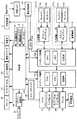
次に、かかる写真自動販売機の機能構成の具体例を図6に示す。 Next, a specific example of the functional configuration of such a photo vending machine is shown in FIG.
図6を参照して、本実施の形態にかかる写真自動販売機は、本写真自動販売機を動作させるための、主に撮影処理などを実行するコンピュータ装置101aと、主に編集処理などを実行するコンピュータ装置101bと(これらを代表してコンピュータ装置101という)、基板から構成され、動作中のコンピュータ装置101からの指示を受付けて、接続されている各種装置を制御する制御部102とを備える。 Referring to FIG. 6, the photo vending machine according to the present embodiment executes a
コンピュータ装置101aは、カメラ21、ライブモニタ22、タッチパネルディスプレイ24、筐体1の内部にあるプリンタ12、および制御部102と接続され、それらを制御する。コンピュータ装置101bは、編集部401a,401bに備えられるタブレットディスプレイ13a,13b、タッチペン14a〜14d、外部と通信するための通信端末110、および筐体1の内部にある制御部102と接続され、それらを制御する。さらに、コンピュータ装置101aとコンピュータ装置101bとは互いに接続され、画像データや情報データなどの授受をピアツーピアで行なう。 The
なお、各コンピュータ装置101a,101bに各々接続される構成要素はこのような形態に限定されず、機能ごとに分かれていたり、位置ごとに分かれていたりしてもよい。さらに、コンピュータ装置101は本実施形態のような2台で構成されていなくてもよく、1台で構成されてもよいし、2台以上で構成されてもよい。 Note that the components connected to the
コンピュータ装置101は、コンピュータ装置101の制御を行なう演算装置であるCPU(Central Processing Unit)と、装置を動作させるためのプログラムおよびプログラムで必要なグラフィックデータ、音声データ、撮影された画像や撮影画像に対して入力した編集画像その他の各種画像などを記憶する記憶部と、プログラムの一時的な作業領域ともなるメモリと、カメラ21、プリンタ12、タブレットディスプレイ13などの周辺機器を制御するためのソフトウェアであるドライバとを含む。また、コンピュータ装置101はLANケーブルを介して外部機器と接続された場合に通信を行なう通信部を備えていてもよい。 The computer apparatus 101 includes a CPU (Central Processing Unit) that is an arithmetic device that controls the computer apparatus 101, a program for operating the apparatus, graphic data necessary for the program, audio data, captured images and captured images. Software for controlling peripheral devices such as a
プリンタ12は、撮影された画像を紙やシールや金属やプラスチックなどの印刷媒体に印刷するためのプリンタであって、昇華型プリンタやサーモオートクローム方式(光定着型直接感熱記録方式)等のプリンタが一般的に用いられる。なお、本実施の形態においてはプリンタ12でシールが印刷されるものとして説明を行なうが、印刷媒体はシールに限定されず、他の印刷媒体であっても同様の処理が実行される。プリンタ12は、上述の用紙切れなどの状態をコンピュータ装置101aに通知する。コンピュータ装置101aは、その状態に応じて制御部102に制御信号を送信する。 The
通信端末110は、本写真自動販売機で使用するために外部で用意された画像を外部装置から受信したり、本写真自動販売機で作成される画像を外部の端末やサーバなどに送信したりするための無線通信可能な端末であって、PHS(Personal Handyphone System)などが用いられる。PHSはカード型のものを用いてもよい。また、外部の端末やサーバなどとインターネット網などのネットワーク網を通じて送受信可能なものであれば、通信端末110はPHSに限定されない。 The
電源スイッチ31が押され、本写真自動販売機に電源プラグより電源が投入されると、上記プログラムが起動されて、コンピュータ装置101aは、接続されるカメラ21のシャッタタイミングや、ライブモニタ22での表示や、タッチパネルディスプレイ24での表示やプリンタ12での出力を制御する。コンピュータ装置101bは、接続されるタブレットディスプレイ13a,13bでの表示を制御する。 When the
コンピュータ装置101aは、上記プログラムの実行や撮影部のタッチパネルディスプレイ24から受信した、ユーザ6の指などでタッチされることによって行なわれる入力操作にしたがった指示信号に基づいて、制御部102に対して制御信号を送信する。 The
また、コンピュータ装置101aは、カメラ21で撮影された画像を受信し該画像データを記憶部へ記憶する。 Further, the
コンピュータ装置101bは、上記プログラムの実行や、編集部401aおよび編集部401bのタブレットディスプレイ13a,13bから受信した、タッチペン14a〜14dなどでタッチされることによって行なわれる入力操作にしたがった指示信号に基づいて、制御部102に対して制御信号を送信する。 The
また、コンピュータ装置101bは、携帯端末やPCなどの外部端末から送信されてくる画像データ等を、通信端末110を介して受信する。これとは逆に、コンピュータ装置101bはコンピュータ装置101bに記憶されている画像データ等を通信端末110から所定のネットワークおよびサーバを介して携帯端末やPCなどの外部端末へ送信することもできる。 The
また、本写真自動販売機は、電源を必要とするコンピュータ装置101、照明装置30、制御部102などの電源系統を制御する電源制御部103を備え、外部からそれらの装置に対する電源の電圧を安定させるよう制御する。さらに、そのような電源の投入および切断は、電源スイッチ31を押すことで行なわれる。しかし、電源切断によりコンピュータ装置101で動作しているプログラムを強制的に終了させることは、動作を不安定にさせる原因となる。そのため、電源が落とされても、しばらくはUPS(Uninterrupted Power Supply)104が電源をバックアップし、コンピュータ装置101に停電信号を送信する。その間に、コンピュータ装置101はプログラムの終了の手続を行ない、プログラムを正常に終了させる。一方、コンピュータ装置101を正規の手順で終了した場合は、その旨の信号がUPS104に送信される。 The photo vending machine also includes a power
制御部102は、コンピュータ装置101および電源制御部103の他に、レリーズスイッチ20、フラッシュ制御部106、スピーカ23a〜23f、サービスパネル105、コイン制御部107、撮影中ランプ7、印刷ランプ9、用紙切れランプ10、エラーランプ11、および背景部5に接続される。 In addition to the computer device 101 and the power
レリーズスイッチ20は、ユーザ6が撮影する時にユーザ所望の撮影するタイミングを指示するためのカメラ21のシャッタ動作を遠隔操作するスイッチである。ユーザ6が、レリーズスイッチ20を押下すると制御部102を介して該制御信号がコンピュータ装置101aに送信され、さらにコンピュータ装置101aから該制御信号がカメラ21に送信されることによって、カメラ21は撮影を行なう。 The
なお、レリーズスイッチ20と制御部102とを接続するケーブルにはLED(Light Emitting Diode)などの発光体を配備してもよい。レリーズスイッチ20を押下すると、カメラ21のシャッタ動作が行なわれるまでの間、レリーズスイッチ20側から制御部120側へ光が移相していくように見えるように発光体を点灯または点滅させ、ケーブルがすべて光った時にシャッタ動作が行なわれる。もちろん、レリーズスイッチ20側から制御部120側へ光が順次消えていくような形態でもよいし、色が変化していくような形態でもよい。このようにすることで、レリーズスイッチ20を押下すると視覚的な演出効果が得られると共に、シャッタ動作のタイミングを視覚的にユーザ6に伝えることができるため、顧客満足を向上させることができる。 In addition, you may arrange | position light-emitting bodies, such as LED (Light Emitting Diode), in the cable which connects the
フラッシュ制御部106は、カメラ21に接続され、カメラ21におけるシャッタタイミングに応じた同期信号を取得する。そして、カメラ21のシャッタタイミングに同期させて、フラッシュを発光させるように制御する。なお、フラッシュ制御部106は制御部102と接続され、発光させるフラッシュ29a〜29h(これらを代表させてフラッシュ29と言う)の選定や、フラッシュ29の発光度の設定がなされる。照明装置30も同様に制御部102と接続され、その照明度合いなどの設定がなされてもよい。 The
スピーカ23a〜23fは、コンピュータ装置101からの指示に従って、制御部102を介して指示信号を受信し、写真自動販売機のプレイにおける操作などの案内や、撮影時のBGMなどを出力する。なお、スピーカ23a〜23fから出力する音声のボリュームを調整する音量調整つまみは、サービスパネル105に備えられる。 The
サービスパネル105は、投入されたコインの枚数をカウントするコインカウンタ、印刷されたプリントの枚数をカウントするプリントカウンタ、スピーカ23から出力する音声のボリュームを調整する音量調整つまみ、テストモードを行なうためのテストボタン、およびコインを投入しなくても装置が利用できるようにするためのサービスボタン等を備えるパネルであって、当該写真自動販売機の設置者が各種設定やメンテナンスの操作を行なう際に用いられる。サービスパネル105は、サービスボタンの操作などの制御操作が行なわれると、その操作にしたがった制御信号を制御部102に対して送信する。 The
制御部102は、コンピュータ装置101から受信した制御信号(指示コマンドなど)にしたがって、サービスパネル105に対して制御信号を送信する。サービスパネル105は、該制御信号に従って、コインカウンタやプリントカウンタを動作させる(たとえば
カウンタを1インクリメントする)。The
コイン制御部107は、コイン投入口26に投入されたコインの正当性を検出し、制御部102にコインが投入されたことを示す検出信号を送信する。 The
制御部102はコンピュータ装置101から受信した制御信号(指示コマンドなど)にしたがって、コイン制御部107に対して制御信号を送信する。コイン制御部107は、該制御信号にしたがって、コインが投入されないようにコイン投入口26をブロックすることができる。このことで、たとえば、プレイ中にコイン投入を禁止することができる。 The
さらに、制御部102はコンピュータ装置101から受信したコインが投入されたことを示す検出信号にしたがって、撮影中ランプ7に対して制御信号を送信し撮影中ランプ7を点灯させる。 Further, the
さらに、制御部102は、コンピュータ装置101aから、プリンタ12の状態に応じた制御信号を受信し、該制御信号にしたがって、印刷中ランプ9a,9b、用紙切れランプ10、およびエラーランプ11を制御する。かかる制御信号によって、印刷中ランプ9a,9b、用紙切れランプ10、およびエラーランプ11が点灯または点滅する。 Further, the
また、制御部102は、コンピュータ装置101aから、タッチパネルディスプレイ24に対してユーザ6が所望の背景を選択する入力操作にしたがった指示信号を受信し、該指示信号にしたがって背景部5のロールスクリーン41の巻取装置42を駆動するモータの動作を制御する。このようにモータの動作を制御することによって、ユーザ6が選択した背景画像が施されたロールスクリーン41が背景部5にセットされる。 In addition, the
ここで、撮影空間3における照明部18の説明を行なう。このような写真自動販売機において、被写体は人間であるユーザ6であることが多い。そこで、本実施の形態においては、被写体が人間であることを前提とする。 Here, the illumination unit 18 in the
原則として、照明部18は箱体で形成され、その箱体内部にはフラッシュ29または蛍光灯などの照明装置30(図6参照)が備えられる。 In principle, the illumination unit 18 is formed of a box, and an illumination device 30 (see FIG. 6) such as a
箱体内面はフラッシュ29などの光源からの照明を効率よく被写体に照射するために、白色で塗装されるなど反射面としての機能を有する。また、フラッシュ29の正面には、フラッシュ29から出射した光を反射させる反射板51a〜51d(これらを代表させ、反射板51と言う)(図7参照)が設けられていてもよい。反射板51には、光を反射させるための白色、銀色、黒色などの加工が施される。これらは、照明部18の配置される位置や求められる機能によって適宜変更され得る。 The inner surface of the box has a function as a reflecting surface, such as being painted white, in order to efficiently irradiate the subject with illumination from a light source such as the
さらに、照明部18の撮影空間3に面する光の出射面には、フラッシュ29a〜29eなどの光源からの光を拡散し、被写体に面状で照射するための拡散板50a〜50g(これらを代表させて拡散板50と言う)(図7参照)が設けられる。ただし、照明部18の構成はこのような構成に限定されるものではなく、照明部18が配置される位置や求められる機能によって適宜変更され得る。 Further, light from the light source such as the
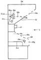
図7を用いて、照明部18a〜18cの位置について説明する。照明部18a〜18cは、カメラ21の上方および下方に、筐体1と一体的に備えられ、被写体を正面から照明する。図7は、筐体1を、照明部18a〜18cを含む面で切断した断面図である。 The positions of the
図7を参照して、照明部18a,18bは、カメラ21の上部に配置され、照明部18cはカメラ21の下部に配置される。 With reference to FIG. 7, the
より具体的には、照明部18a,18bは、図7に示される断面においてカメラ21よりも上方に位置し、照明部18a,18bが一体となって、上方に向かうにつれてカメラ21の撮影方向に対して張出す形状、つまり、筐体1を正面側から見た場合に撮影空間3側に張出した形状を奏する。 More specifically, the
また、照明部18cは、カメラ21よりも下方に位置し、下方に向かうにつれてカメラ21の撮影方向に対して張出す形状、つまり、筐体1を正面側から見た場合に撮影空間3側に張出した形状を奏する。そのカメラ21の撮影方向に対して張出す距離は、照明部18a,18bが一体となってカメラ21の撮影方向に対して張出す距離よりも短い。 Moreover, the
照明部18a〜18cをこのような構成とすることで、撮影空間3の広さを確保できる。 By making the
さらに、各照明部18a〜18cの詳細な構成および機能について、図7〜図11を用いて説明する。 Furthermore, the detailed structure and function of each
図8(A)は、照明部18aの内部と照明部18bの内部とを正面から見た図である。 FIG. 8A is a view of the inside of the
図8(A)を参照して、照明部18aは、照明部18bの周囲を覆うような形で配置されており、照明部18aは、図7に示される断面においては照明部18bよりも上方に位置する。また、照明部18bは、照明部18aに周囲を覆われるような形で配置されており、図7に示される断面においては照明部18aよりも下方に位置する。 With reference to FIG. 8 (A), the
図7および図8(A)を参照して、照明部18aは、その内部にフラッシュ29a〜29cと、フラッシュ29bから発光された光を反射する反射板51aと、フラッシュ29cから発光された光を反射する反射板51bと、図示されない照明装置30aとを含んで構成される。 With reference to FIG. 7 and FIG. 8 (A), the illuminating
図8(A)を参照して、フラッシュ29aは、照明部18aの略中心付近に位置し、カメラ21の撮影方向に相対して、正面を向いてカメラ21の前に立った被写体の、髪付近を照射する。 Referring to FIG. 8A, the
さらに図8(A)を参照して、正面から見て、フラッシュ29bはフラッシュ29aの左側斜め下に配置され、フラッシュ29cはフラッシュ29aの右側斜め下に配置される。すなわち、フラッシュ29b,29cは、フラッシュ29aを含む縦方向の線に対して線対称となる位置関係で配置される。 Further, referring to FIG. 8A, when viewed from the front, the
図8(B)は照明部18aの内部と照明部18bの内部とを側面から見た図である。 FIG. 8B is a view of the inside of the
図7および図8(B)を参照して、フラッシュ29b,29cは、フラッシュ29aより、被写体から遠い側に配置される。 Referring to FIGS. 7 and 8B, flashes 29b and 29c are arranged on the side farther from the subject than
また、図7および図8(A)を参照して、照明部18aは、撮影空間3に面する光の出射面に先述した拡散板50aを、照明部18bとの上下方向の境界面に拡散板50bを、照明部18bとの左右方向の境界面に拡散板50c,50dを備える。拡散板50a〜50dには、乳白色のアクリル板やシートなどが用いられる。拡散板50aによって光を拡散して出射するため、照明部18aから被写体の髪付近に対して柔らかい光質の光を出射できる。また、拡散板50b〜50dは照明部18aと照明部18bとを区分し、照明部18aから出射される光と照明部18bから出射される光との直接的な干渉を防止している。 Referring to FIGS. 7 and 8A, the
さらに、拡散板50b〜50dによって、それぞれの照明部18から照射される光が互いに間接的に干渉する。このことにより、照明部18aから出射される光と照明部18bから出射される光とが完全に分断されることはないため、不必要な影が映ることや暗くなりすぎることを防止できる。 Furthermore, the light irradiated from each illumination part 18 interferes mutually indirectly by the diffusing
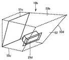
図9は、照明部18bの斜視図である。 FIG. 9 is a perspective view of the
図7および図9を参照して、照明部18bは、その内部にフラッシュ29dと、フラッシュ29dから発光した光を反射する反射板51cとを含んで構成される。 Referring to FIGS. 7 and 9,
図8(A)を参照して、フラッシュ29dは、照明部18bの略中心より下方付近であって、照明部18aのフラッシュ29aの下方に位置し、カメラ21の撮影方向に相対して、正面を向いてカメラ21の前に立った被写体の、顔付近を照射する。 Referring to FIG. 8A, the
さらに図7および図9を参照して、照明部18bは、撮影空間3に面する光の出射面に、光を直接透過する透過板52を、照明部18aとの上下方向の境界面に拡散板50bを、照明部18aとの左右方向の境界面に拡散板50c,50dを備える。透過板52は、透明な板やシートなどが用いられる。また、照明部18bは、図7に示されるように、カメラ21の上方に、カメラ21を含む面に接して位置し、その透過板52の下辺はカメラ21を含む面と接している。 Further, referring to FIGS. 7 and 9, the
照明部18aに設けられる拡散板50aと照明部18bの透過板52とは、透過板52の下辺以外の辺を囲むように一体的に形成される。いうまでもなく、下辺を含むすべての辺を囲むように形成されてもよい。拡散板50aと透過板52とは一体となって、下方に向かうにつれてカメラ21の撮影方向と反対方向に落込むように傾斜して配置される。このような構成であることで、照明部18a,18bは、撮影時には後に説明する照明部18cに向かって光を照射しやすい。 The diffusing
上述のように、照明部18aと照明部18bとでは、光の出射面が異なるように形成されている。そのため、照明部18aと照明部18bとでは、出射する光の光質が異なる。具体的には、照明部18aは、拡散板50aによって光を拡散して、柔らかい光質の光を、主に被写体の髪付近に対して出射する。一方、照明部18bは、透過板52によって光を直接透過して、硬くてシャープな光質の光を拡散せず直接に、主に被写体の顔付近に対して出射する。このため被写体の部分ごとに異なる写り具合を実現することができる。 As described above, the illuminating
なお、照明部18bの透過板52が透明であると、内部のフラッシュ29dがむき出しになってしまい見栄えがよくない。このため、透過板52を、電流を通すとガラスが曇り、すりガラス状になるマジックガラスなどを用いて形成したり、すりガラス状になっている部分と透明部分とを交互に持つストライプ状に形成したりしてもよい。また、通常は目隠し用の板を出射面に配置しておき、撮影時に透過板が出射面に配置されるようにしてもよい。これは、シャッタ式やスライド式や巻取り式などの方法によって実現されるが、限定するものではない。このようにして、照明部18bの中が見えにくいようにしておくことが好ましい。 If the
図10は、照明部18cの斜視図である。 FIG. 10 is a perspective view of the
図7および図10を参照して、その内部にフラッシュ29eと、フラッシュ29eから発光された光を反射する反射板51dと、図示されない照明装置30aとを含む。 Referring to FIGS. 7 and 10,
また、撮影空間3に面する光の出射面に、上部から順に3面の拡散板50e〜50gを備える。 Further, on the light emission surface facing the
図10を参照して、フラッシュ29eは、照明部18cの略中心付近に位置し、拡散板50gを介して出射される光は、カメラ21の撮影方向に相対して、正面を向いて撮影空間3内の後方に立った被写体の、足元付近を照射する。また、拡散板50e,50fを介しては、照明部18a,18b方向へ出射される。 Referring to FIG. 10, the
3面の拡散板50e〜50gは、各々、水平方向の傾斜角を異なるように形成される。より具体的に、拡散板50eは床面に対する傾斜角を拡散板50fの床面に対する傾斜角よりも大きく形成され、拡散板50gは床面に対して垂直に形成されている。ここでは、このように拡散板50を分けて出射面を形成しているが、限定するものではなく上述のような角度の出射面を形成するものであれば一体的に形成されていても構わない。 The three
また、拡散板50e〜50gは、下方に向かうにつれてカメラ21の撮影方向に対して張出すように傾斜して配置される。このような構成であることで、照明部18cは、撮影時には照明部18a,18bに向かって光を照射しやすい。 Further, the
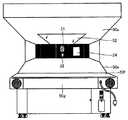
このように照明部18cを形成することによって、図11に示されるように、ユーザ6は照明部18cの拡散板50eが形成する面に腕を置き、拡散板50fが形成する面に肘を付いて撮影ができるようになっている。そこで、拡散板50fの高さは、ユーザ6の肘程度の高さであることが好ましい。または、拡散板50fの高さがユーザ6の肘程度の高さとなるよう、撮影空間3の下方(床面)に踏み台などが備えられていてもよい。このため、撮影時に、ユーザ6が肘をつくことができて、肘をついたポーズが容易に撮影できる。また、肘をついて撮影することにより、リラックスした雰囲気で撮影ができるため、表情が柔らかくなりやすいため、ユーザ6の望むような写真が得られやすくなる。 By forming the
次に、図12を用いて、照明部18とカメラ21との位置関係について説明する。カメラ21は、照明部18a,18bと照明部18cとの間に配置される。 Next, the positional relationship between the illumination unit 18 and the
図12は、筐体1に備えられる照明部18a〜18cを正面から見た図であり、図12を参照して、カメラ21を含む面のカメラ21の右側には、タッチパネルディスプレイ24が備えられ、カメラ21を含む面のその部分は、光が透過しないように構成されている。このため、光のバランスが崩れないように、カメラ21を含む面のカメラ21の左側にも光を透過しないような不透過部材が備えられ、光が透過しないように構成されている。 FIG. 12 is a view of the
また、ちょうどカメラ21を含む面と同じ高さに被写体の瞳が位置することが多いため、不透過部材やカメラ21の周囲には黒色が施されている。このようにすることで、被写体の瞳を黒くはっきりした写り具合にすることができる。また、黒味が入ることにより顔の写り具合が引き締まった印象となる。 Further, since the pupil of the subject is often located at the same height as the plane including the
このようにして、筐体1と一体化して備えられる照明部18a〜18cは、側方から見てカメラ21が配置される面を谷とした「くの字型」を奏する凹型に配置される。すなわち、カメラ21の撮影方向(光軸方向)に略直交する方向に、カメラ21を有する面を谷とする凹型を形成する。このような「くの字型」に照明部18a〜18cを配置することにより、光が直接被写体に向けて照射されずに、照明部18a,18bから照射した光が照明部18cに反射し、照明部18cから照射した光が照明部18a,18bに反射し光が互いに干渉しあい散乱することにより、間接的な柔らかい光質の光を被写体全体に照射することができる。このようにすることにより、直接被写体に光を照射する場合よりも柔らかい照明効果を実現することができ、出来上がりが美しい画像が得られる。また、平面状に照明部18a〜18cを構成した場合よりも、光の陰影が出るため、写り具合が立体的になる。 Thus, the illuminating
このように「くの字型」を奏する凹型に照明部18を形成することで、全体的にふんわりと柔らかそうな質感で写すことを可能とする。このため、このような写真自動販売機を利用することが多い世代の好みにあった写真が撮影できる。 In this way, by forming the illumination unit 18 in a concave shape that has a “K” shape, it is possible to capture the image with a soft and soft texture as a whole. For this reason, it is possible to take a photo that suits the taste of the generation who often uses such a photo vending machine.
具体的に、図13および図14を用いて、各照明部18a〜18cから照射される光の方向について説明する。 Specifically, the direction of light emitted from each of the
図13は、照明部18aの略中央に含まれるフラッシュ29a、照明部18bの略中央に含まれるフラッシュ29d、および照明部18cに含まれるフラッシュ29eを用いた場合の、照明部18a〜18cから出射される光の方向を簡略的に表わす図である。 FIG. 13 shows emission from the
図13を参照して、照明部18aに含まれるフラッシュ29aから出射された光は、箱体で構成される照明部18aの内側で反射を繰返し、拡散板50aで光が拡散され撮影空間3に向けて出射される。この光は被写体全体を照射するが、特に、照明部18aが図示される位置に配置されることから、被写体の頭頂部付近を柔らかい光で照射する。また、図13には示されていないが、フラッシュ29aから出射された光の一部は、照明部18aと照明部18bとの境目に構成される拡散板50b〜50dで拡散されて照明部18bにも入射し、照明部18bの透過板52からも出射される。 Referring to FIG. 13, the light emitted from the
照明部18bに含まれるフラッシュ29dから出射された光は、銀色の反射板51cによって反射し、透過板52を通して直接被写体の顔付近を照射する。また、図13には示されていないが、フラッシュ29dから出射された光の一部は、照明部18aと照明部18bとの境目に構成される拡散板50b〜50dで拡散されて照明部18aにも入射し、照明部18aの拡散板50aからも出射される。 The light emitted from the
照明部18cに含まれるフラッシュ29eから出射された光は、拡散板50e,50fで拡散されて照明部18a,18b方向へ出射される。また、拡散板50gで拡散されて、被写体の足元付近を照射する。 The light emitted from the
つまり、照明部18による照明を、照明部18aの略中央に含まれるフラッシュ29a、照明部18bの略中央に含まれるフラッシュ29d、および照明部18cに含まれるフラッシュ29eを用いた構成とすることにより、図13に示されるような照明が行なわれ、被写体の顔を全体的にシャープな印象で撮影することができる。また、被写体髪の毛などの部分はこのようなシャープな光質の光を照射して撮影すると、痛んだ髪などを目立たせてしまうことになるが、髪の毛へは照明部18aからソフトな光質の光を照射することにより、顔はシャープで、髪の毛はソフトという理想的な写り具合を実現することができる。 That is, the illumination by the illumination unit 18 is configured using the
また、照明部18aの略中央に含まれるフラッシュ29dのみで撮影すると顔だけに光が当たりすぎてしまい、顔以外の頭部分などが影になってしまうが、他のフラッシュと組合わせる構成とすることで、自然な美しい写り具合を実現できる。 In addition, if only the
図14は、照明部18aの略中央より斜め下に含まれるフラッシュ29b,29c、照明部18bに含まれるフラッシュ29d、および照明部18cに含まれるフラッシュ29eを用いた場合の、照明部18a〜18cから出射される光の方向を簡略的に表わす図である。 FIG. 14 shows
図14を参照して、照明部18aに含まれるフラッシュ29b,29cから出射された光は、各々黒色の反射板51a,51bで反射し、箱体で構成される照明部18aの内側で反射を繰返し、拡散板50aで光が拡散され撮影空間3に向けて出射される。この光は被写体全体を照射するが、特に、照明部18aが図示される位置に配置されることから、被写体の頭頂部付近を柔らかい光で照射する。また、図14には示されていないが、フラッシュ29b,29cから出射された光の一部は、照明部18aと照明部18bとの境目に構成される拡散板50b〜50dで拡散されて照明部18bにも入射し、照明部18bの透過板52からも出射される。 Referring to FIG. 14, light emitted from
照明部18bに含まれるフラッシュ29dから出射された光は、上述のように、銀色の反射板51cによって反射し、透過板52を通して直接被写体の顔付近を照射する。また、その一部は、照明部18aと照明部18bとの境目に構成される拡散板50b〜50dで拡散されて照明部18aにも入射し、照明部18aの拡散板50aからも出射される。 The light emitted from the
照明部18cに含まれるフラッシュ29eから出射された光は、上述のように、拡散板50e,50fで拡散されて照明部18a,18b方向へ出射される。また、拡散板50gで拡散されて、被写体の足元付近を照射する。 As described above, the light emitted from the
つまり、照明部18による照明を、照明部18aの略中央より斜め下に含まれるフラッシュ29b,29c、照明部18bに含まれるフラッシュ29d、および照明部18cに含まれるフラッシュ29eを用いた構成とすることにより、図14に示されるような照明が行なわれ、被写体を全体的にソフトな印象で撮影することができる。 That is, the illumination by the illumination unit 18 is configured using the
あるいは、照明部18aと照明部18bとに、それぞれ補助的なフラッシュ29を備えてもよい。このようにすることで、光量が弱くなることを防止することができる。 Or you may equip the
また、照明部18aと照明部18bとで異なる光質を実現するために、照明部18aと照明部18bとの光源であるフラッシュ29の光量が異なるように形成してもよいし、フラッシュ29の位置や反射板51の位置や材質や色によって光質を調整してもよい。また、照明部18aは通常写真自動販売機で用いられことが多いストロボを使用し、照明部18bはオパライトを使用するなど、発光特性の異なるフラッシュを用いることにより異なる光質を実現してもよい。なお、異なる光質は、発光特性の違いや材質の違いなどの光質の決定要素が複数組合わせされて実現されてもよいし、単独の光質の決定要素で実現されてもよい。 Further, in order to achieve different light qualities between the illuminating
このように、本実施の形態にかかる写真自動販売機における照明部の構成によって、フラッシュ29a,29dを用いたシャープな写り具合と、フラッシュ29b,29cを用いたソフトな写り具合とのいずれの写り具合も、1つの写真自動販売機で実現できる。そのため、ユーザ6の個々の好みに対応した写り具合を実現できる。また、このような構成にすることにより、コストを軽減できる。 Thus, depending on the configuration of the illumination unit in the photo vending machine according to the present embodiment, either a sharp image using the
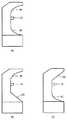
なお、このように被写体の正面を写す照明部18は「くの字型」に形成され、それぞれの照明部18の光を出射する面は平面で構成されている形態に限定されず、たとえば、図15(A)に示されるように、光を出射する面が曲面で構成され、「お椀型」に形成されていてもよい。あるいは、図15(B)に示されるように、照明部18a,18bにあたる上部が曲面、照明部18cにあたる下部が平面で構成されてもよいし、図15(C)に示されるように、照明部18a,18bにあたる上部が平面、照明部18cにあたる下部が曲面で構成されていてもよい。このようにすることにより、前述のように、上部の照明部18と下部の照明部18とから光を直接被写体へ照射するのでなく、間接的な柔らかい照射を行なうことができる。 In addition, the illumination unit 18 that captures the front of the subject in this way is formed in a "<" shape, and the surface of each illumination unit 18 that emits light is not limited to a plane configuration. As shown in FIG. 15A, the surface from which light is emitted may be a curved surface and may be formed in a “bowl shape”. Alternatively, as shown in FIG. 15 (B), the upper part corresponding to the
次に、図16を用いて、照明部18d〜18fの位置について説明する。照明部18d〜18fは、撮影空間3の後方や上方に当たる部分に配置され、被写体を背後から照明する。 Next, the positions of the
図16を参照して、照明部18dは撮影空間3内の後方の天井面に配置され、照明部18e,18fは撮影空間3内の後方の両側面にそれぞれ配置される。 Referring to FIG. 16, the
照明部18dは、その内部にフラッシュ29fを備える。また、その後方が下がるように傾斜して配置される、図示されない拡散板を備える。フラッシュ29fから出射される光はその拡散板で拡散されて、撮影時には、撮影空間3の略中央に位置する被写体の頭頂部後方部分を照射する。 The
照明部18e,18fは、各々その内部にフラッシュ29g,29hを備える。また、各々、その面が撮影空間の略中心方向を向くように配置された、図示されない拡散板を備える。フラッシュ29g,29hから出射される光は各々その拡散板で拡散されて、撮影時には、撮影空間の略中央に位置する被写体の左右斜め後方部分を照射する。 The
さらに図16を参照して、照明部18d〜18fの内部に備えられる図示されない拡散板の前面には、フラッシュ29から出射し拡散板50から拡散して出射する光を擬似的に平行光とするためのグリッドと呼ばれる格子状の部材が配備される。また、グリッドの前面にはグリッドの格子の中にゴミなどがつまったり、ユーザ6によってゴミなどを入れられたりすることを防止するために、光を透過する透明な保護部材が備えられることが好ましい。 Further, referring to FIG. 16, light emitted from the
このように、被写体の頭部付近を被写体の背後から照射することにより、髪の毛が美しく撮影できる。 In this way, by irradiating the vicinity of the subject's head from behind the subject, the hair can be photographed beautifully.
なお、言うまでもなく、写真自動販売機の形態は図1〜図16に示される具体例に限定されるものではない。すなわち、図1〜図16に記載されない他の機能が備えられていてもよいし、図1〜図16に記載されている機能の必ずしもすべてが備えられていなくても構わない。たとえば、プリンタ12は写真自動販売機本体に含まれていなくてもよく、その場合、写真自動販売機は、LAN等の専用回線や無線通信等を介して印刷制御信号をプリンタ12に出力するものとする。 Needless to say, the form of the photo vending machine is not limited to the specific examples shown in FIGS. That is, other functions not shown in FIGS. 1 to 16 may be provided, or not all of the functions shown in FIGS. 1 to 16 may be provided. For example, the
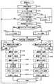
次に、本実施の形態にかかる写真自動販売機の処理について、図17を用いて説明する。図17のフローチャートに示される写真自動販売機の処理は、コンピュータ装置101のCPUが、記憶部に記憶されるプログラムをメモリに読出して実行することによって実現される。 Next, processing of the photo vending machine according to the present embodiment will be described with reference to FIG. The processing of the photo vending machine shown in the flowchart of FIG. 17 is realized by the CPU of the computer apparatus 101 reading a program stored in the storage unit into the memory and executing it.
図17を参照して、始めに、当該写真自動販売機に備わる電源スイッチ31が投入されて各種装置の電源が投入される。すると、コンピュータ装置101の記憶部に格納された動作プログラムが起動する。コンピュータ装置101は、各種装置が正常に接続されているかチェックし、初期化が必要な装置に対しては初期化を行なう(S100)。このとき、写真自動販売機の利用回数(n)の初期化も同時に行なわれる。たとえば、記憶部の所定のファイルに利用回数(n)の値を記憶し、その値を0にすることなどによって初期化が行なわれる。その後、当該写真自動販売機の利用を促すタイトルデモをディスプレイ24に表示し、同時に音声をスピーカ23a〜23dから出力する(S105)。 Referring to FIG. 17, first, a
タイトルデモが表示されている状態において、テストボタンの押下(S110)と所定の対価受付とが監視される(S120)。 In the state where the title demo is displayed, the pressing of the test button (S110) and the reception of a predetermined value are monitored (S120).
テストボタンが押下されると(S110でYES)、当該写真自動販売機のメンテナンスを行なうためのテストモードが起動する(S115)。テストモードは、写真自動販売機の設置者が写真自動販売機を操作するためのモードであり、このモードにおいては当該写真自動販売機の利用状況(たとえばコイン投入数など)の確認や、利用回数(n)の初期化や設定、利用できる編集部の設定、カメラ21、プリンタ12など周辺機器の調整を行なうことができる。ここで写真自動販売機の設置者とは、当該写真自動販売機を設置し営業を行なっている店舗などの経営者、管理者、および従業員であり、営業中に、利用者に対応できるものである。 When the test button is pressed (YES in S110), a test mode for performing maintenance of the photo vending machine is activated (S115). The test mode is a mode for the operator of the photo vending machine to operate the photo vending machine. In this mode, the usage status (for example, the number of coins inserted) of the photo vending machine is checked and the number of times of use is checked. Initialization and setting of (n), setting of available editing units, and adjustment of peripheral devices such as the
テストボタンが押下されておらず(S110でNO)、コイン投入口26において、当該写真自動販売機を利用するためのコインの投入(所定の対価)を受付けると(S120でYES)、受付けたコインは、コイン制御部107において正当性や枚数等が検知される。そして、正常にコインを受付けるとプレイが開始され、さらに、当該写真自動販売機の利用回数(n)がカウントされる(S125)。この利用回数(n)のカウントには、写真自動販売機を無料で利用させる機能が備わる場合、その利用回数が含められてもよいし、含められなくてもよい。 If the test button has not been pressed (NO in S110) and a coin insertion (predetermined price) for using the photo vending machine is accepted at the coin insertion slot 26 (YES in S120), the accepted coin In the
なお、利用回数(n)をカウントするタイミングは、上述のような正当な対価の検出によって行なうものに限定されるものではなく、たとえば、撮影終了時、または印刷終了時など、写真自動販売機におけるプレイが行なわれたと判定できるようなタイミングであればいつでもよい。 Note that the timing of counting the number of uses (n) is not limited to that performed by detecting the valid price as described above. For example, in a photo vending machine at the end of shooting or at the end of printing. Any timing can be used as long as it can be determined that play has been performed.
写真自動販売機のコンピュータ装置101のCPUは、利用回数(n)が奇数である場合には編集空間4aに、利用回数(n)が偶数の場合には編集空間4bにユーザ6を誘導するよう、処理を割当てる。または、利用回数(n)が偶数の場合には編集空間4aに、利用回数(n)が奇数の場合には編集空間4bにユーザ6を誘導するよう処理を割当ててもよい。また、編集空間4に関する処理の割当はこのような形態に限定されず、ユーザ6が編集操作で使用したい編集空間4を選択し、その選択に従って割当ててもよい。なお、編集空間4に関する処理の割当についての設定は、テストモードなどで設置者が設定可能なようにしておくことが好ましい。 The CPU of the computer device 101 of the photo vending machine guides the
さらに、テストモードにおいて、利用回数を参照しないで編集空間4のいずれか一方のみを利用可能にするような設定ができるようにしてもよい。このようにすることで、装置の故障で2つの編集空間4のいずれかが使用できないという事態が発生したとしても、故障していない方の編集空間4のみを使用するようにできる。また、装置の故障を検出したら、自動的に故障してない方の編集空間4のみを使用するように設定変更がなされるようにしてもよい。 Furthermore, in the test mode, settings may be made so that only one of the editing spaces 4 can be used without referring to the number of uses. In this way, even if a situation occurs in which one of the two editing spaces 4 cannot be used due to a device failure, only the editing space 4 that is not in failure can be used. Further, when a failure of the apparatus is detected, the setting may be changed so that only the editing space 4 that has not failed automatically is used.
次に、ステップS125で利用回数(n)がカウントされた後、撮影コースの選択を受付ける(S130)。本実施の形態においては、撮影方法に複数のコースがあるものとする。ステップS130では、撮影コースの選択肢をタッチパネルディスプレイ24に提示し、好みの撮影コースをユーザ6から受付ける。 Next, after the number of uses (n) is counted in step S125, the selection of the shooting course is accepted (S130). In the present embodiment, it is assumed that there are a plurality of courses in the photographing method. In step S130, shooting course options are presented on the
具体的に撮影コースとしては「ノーマル撮影」コースと「フリー撮影」コースとがあり、タッチパネルディスプレイ24に表示される選択肢の該当領域をユーザ6の指などでタッチすることにより選択を受付ける。そして、選択された撮影コースが「ノーマル撮影」なら(S130でYES)該コースの撮影方法で撮影が開始され(S135)、選択された撮影コースが「フリー撮影」なら(S130でNO)該コースの撮影方法で撮影が開始される(S140)。各々の撮影処理については、さらにサブルーチンを挙げて後述する。 Specifically, the shooting course includes a “normal shooting” course and a “free shooting” course, and a selection is accepted by touching a corresponding area of options displayed on the
ステップS135での「ノーマル撮影」またはステップS140での「フリー撮影」が終了すると、ステップS125でカウントされた写真自動販売機の利用回数(n)が、奇数回目なら(S145でYES)、編集部401aが利用可能かどうかが監視される(S150)。先にプレイしている別グループの利用者が利用中または故障中であるなど、編集部401aが利用不可な状態であれば(S150でNO)、タッチパネルディスプレイ24に待機表示、またはエラーの案内表示をし、スピーカ23a〜23dから音声で待機、またはエラーの案内を出力することにより、ユーザ6を撮影空間3で待機させるように促す(S155)。 When the “normal shooting” in step S135 or the “free shooting” in step S140 is completed, if the number of times the photo vending machine is used (n) counted in step S125 is an odd number (YES in S145), the editing unit It is monitored whether or not 401a is available (S150). If the
編集部401aが利用可能な状態であれば(S150でYES)、タッチパネルディスプレイ24に編集部401aのある編集空間4aへ誘導する案内表示をし、スピーカ23a〜23dから音声で誘導案内を出力することにより、ユーザ6を編集空間4aに移動させるように促す(S160)。そして、コンピュータ装置101aに記憶されている該ユーザ6の撮影画像データをコンピュータ装置101bの記憶部の編集部401aでの処理実行用の領域へ転送し(S165)、処理を編集処理へ移行する(S190)。 If the
一方、ステップS125でカウントされた写真自動販売機の利用回数(n)が、偶数回目なら(S145でNO)、編集部401bが利用可能かどうかが監視される(S170)。先にプレイしている別グループの利用者が利用中または故障中であるなど、編集部401bが利用不可な状態であれば(S170でNO)、タッチパネルディスプレイ24に待機表示、またはエラーの案内表示をし、スピーカ23a〜23dから音声で待機、またはエラーの案内を出力することにより、ユーザ6を撮影空間3で待機させるように促す(S175)。 On the other hand, if the usage count (n) of the photo vending machine counted in step S125 is an even number (NO in S145), it is monitored whether the
編集部401bが利用可能な状態であれば(S170でYES)、タッチパネルディスプレイ24に編集部401bのある編集空間4bへ誘導する案内表示をし、スピーカ23a〜23dから音声で誘導案内を出力することにより、ユーザ6を編集空間4bに移動させるように促す(S180)。そして、コンピュータ装置101aに記憶されている該ユーザ6の撮影画像データをコンピュータ装置101bの記憶部の編集部401bでの処理実行用の領域へ転送し(S185)、処理を編集処理へ移行する(S190)。 If the
ユーザ6は前述のような案内に従って編集空間4aまたは編集空間4bへ移動する。そして、以降のユーザ6の操作は、編集空間4aまたは編集空間4bで行なわれる。 The
このように編集操作をする空間を複数用意することにより、編集時間を長くすることができたり、順番待ちの時間を短縮することができたりし、ユーザ6の顧客満足度を向上させることができる。また、順番待ちの時間を短縮できるため、本写真自動販売機の稼動回転率を向上することができる。さらに、ユーザ6を編集空間4aと編集空間4bとにおいて交互に編集させるため次々にユーザ6が入替わり、順番を待機している利用者には人気機種に写ってさらなる集客効果が得られる。 By preparing a plurality of spaces for editing operations in this way, the editing time can be lengthened, the waiting time for the order can be shortened, and the customer satisfaction of the
なお、ステップS190以降の編集空間4aおよび編集空間4bでの編集処理の内容は、場所や位置、装置などは異なるが、同様な構成であり、同様な処理が行なわれるため、説明の重複部分は繰返さない。各編集空間4での処理はコンピュータ装置101bによって制御される。 The contents of the editing process in step S190 and subsequent steps in the
ステップS190においては、撮影画像に対して、ユーザ6からタッチペン14により編集入力を受付ける編集処理が行なわれる。その編集入力時間は予め設定されている。そして、タブレットディスプレイ13上に残り時間が表示されてカウントダウンされ、残り時間が0になると編集入力が終了する。または、画面に用意された「終了」ボタンを押すことで強制的に終了させることもできる。なお、ステップS190における編集処理については、後に詳述する。 In step S190, an editing process for receiving an editing input from the
ステップS190の編集入力が終了すると、撮影画像と編集入力された画像とを合成し、合成された画像をタブレットディスプレイ13に表示する。そして、ユーザ6から、シール等の印刷媒体に印刷する画像の取扱いに関する設定や、選択の変更を受付ける(S195)。また、印刷を行なう画像の選択や、編集入力に失敗した画像などを印刷しないような選択を受付けることもできる。ステップS195における印刷画像の取扱設定についても、後に詳述する。 When the editing input in step S190 ends, the captured image and the input image are combined, and the combined image is displayed on the tablet display 13. Then, the
そして、ステップS195で選択された画像の枚数に応じて、予め決められた複数の印刷レイアウトをタブレットディスプレイ13に表示し、ユーザ6の選択を受付ける(S200)。 Then, a plurality of predetermined print layouts are displayed on the tablet display 13 according to the number of images selected in step S195, and the selection of the
ステップS195およびステップS200において印刷する画像の選択と印刷レイアウトの選択とを受付けると、選択された印刷レイアウトにしたがって印刷画像データが生成され、プリンタ12から印刷出力される。すなわち、生成された印刷画像データはコンピュータ装置101bからコンピュータ装置101aへ転送され(S205)、コンピュータ装置101aの制御によって該印刷画像データはプリンタ12へ出力される。さらに、ユーザ6をプリンタ12の前に誘導する案内(たとえば「シールは右から出るよ!」)を各編集空間4に配備されているスピーカ23e,23fまたはタブレットディスプレイ13a,13bより出力する。そして、プリンタ12で印刷が実行され(S205)、プリント取出口8よりユーザ6に提供される。 When the selection of the image to be printed and the selection of the print layout are accepted in step S195 and step S200, print image data is generated according to the selected print layout and printed out from the
以上の処理が、1組のユーザ6によって本実施の形態の写真自動販売機で行なわれるプレイである。そして、上述の処理が終了すると、次にコインが投入されるまで、再度待機画面が編集空間4に配備されているタブレットディスプレイ13a,13bより出力される。 The above processing is a play performed by a set of
なお、上述の実施の形態では、1組のユーザ6が利用する形態を説明したが、図1に示されるとおり、撮影を行なう撮影空間3と撮影された画像に編集を行なう編集空間4とが異なる場所に設置されていることから、2組の利用者が同時に利用することもできる。この場合、先の利用者が撮影を終了し編集空間4に移動するとディスプレイ24にはデモ画像が表示され、次の利用者のコイン投入を受付ける。そして、コインが投入されると、次の利用者の撮影が開始される。なお、本装置においては、撮影空間3と編集空間4とを異なる位置に設けるように説明したが、これに限定されるものではなく、1つの空間において、撮影および編集が行なわれるようにしてもよい。 In the above-described embodiment, the form used by one set of
さらに以下に、上述のプレイに含まれるいくつかの処理について、詳細な説明を行なう。 Further, a detailed description will be given below of some processes included in the above-described play.
[ノーマル撮影コース]
上述のステップS135で実行される「ノーマル撮影」コースについて、図18のフローチャートを用いてその処理を説明する。[Normal shooting course]
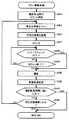
The process of the “normal shooting” course executed in step S135 described above will be described with reference to the flowchart of FIG.
図18を参照して、図17のステップS130の撮影コース選択において「ノーマル撮影」が選択されると、タッチパネルディスプレイ24に背景選択画面を表示し、ユーザ6に背景選択を促す(S300)。ユーザ6から背景画像が選択されると、コンピュータ装置101aから制御部102へ選択された背景画像を示す指示信号が送信される。制御部102は、該指示信号に基づいて背景部5の巻取装置42を駆動するモータを動作させることによって、選択された背景画像を背景部5にセットする。 Referring to FIG. 18, when “normal shooting” is selected in the shooting course selection in step S130 of FIG. 17, a background selection screen is displayed on
次に、ステップS300において背景が選択されると、タッチパネルディスプレイ24に図19に示される画質選択画面を表示し、ユーザ6に画質の選択を促す(S305)。ここで言う画質とは撮影画像の撮影画像の明るさや写り具合を指す。 Next, when a background is selected in step S300, the image quality selection screen shown in FIG. 19 is displayed on the
図19を参照して、画質選択画面では、柔らかい写り具合の具体例を示す選択肢とシャープな写り具合の具体例を示す選択肢とを選択可能に提示して、どちらか写り具合を選択することができる。また、他の選択肢として、柔らかい写り具合とシャープな写り具合との他に、それらの中間の写り具合や、大人数用、少人数用などの写り具合などの選択肢があってもよい。 Referring to FIG. 19, on the image quality selection screen, an option indicating a specific example of a soft image condition and an option indicating a specific example of a sharp image condition are presented to be selectable, and either one of the image conditions can be selected. it can. As other options, there may be options such as a soft image and a sharp image, an intermediate image, or a large image and a small image.
図19に示される画質選択画面においてユーザ6から画質が選択されると、コンピュータ装置101aから制御部102へ選択された画質を示す指示信号が送信される。制御部102は、該指示信号に基づいてフラッシュ29や照明装置30の選定や設定の変更を行なうことで、その選択に合わせた光質に変更し、選択された画質の撮影画像を実現する。あるいは、カメラ21の設定を変更したり、コンピュータ装置101aの設定ファイルに基づいて画像処理を撮影画像に施したりすることにより、選択された画質の撮影画像を実現してもよい。 When an image quality is selected by the
次に、ステップS305における画質の選択が終了すると、図示されない写真自動販売機のタイマは計時(カウント)を開始する(S310)。カウントが開始されると所定時間に達しているかが判定され、所定時間に達するまでカウントを継続する(S315でNO)。そして、時間経過と共に「3、2、1」などのカウントダウンをタッチパネルディスプレイ24あるいはスピーカ23a〜23dに出力する。カウントが終了したと判定されると(S315でYES)、撮影が行なわれる(S320)。 Next, when the selection of image quality in step S305 is completed, a timer of a photo vending machine (not shown) starts counting (counting) (S310). When the count is started, it is determined whether the predetermined time has been reached, and the count is continued until the predetermined time is reached (NO in S315). Then, a countdown such as “3, 2, 1” is output to the
ステップS320での撮影は、コンピュータ装置101aからカメラ21に撮影信号が送信されることでシャッタが切られ、同時にフラッシュ制御部106によってフラッシュ29が発光することで実行される。 Shooting in step S320 is performed by releasing a shutter when a shooting signal is transmitted from the
1回の撮影が終了すると、連続で撮影する規定回数(ここでは2回)分撮影がされたかが判定され(S325)、規定回数に達するまでステップS320の撮影が連続して行なわれる(S325でNO)。連続で撮影する規定回数に達している場合(S325でYES)、所定のセット数(ここでは連続2回の撮影が3セット)の撮影処理が行なわれたかが判定され(S330)、所定のセット数撮影されていなければ(S330でNO)、ステップS300に処理を戻し、再び背景選択から始まる撮影処理が繰返される。そして、所定のセット数の撮影が終了すると(S330でYES)、撮影された撮影画像に対する格付けや順位付けなどの評価付け、取扱いの設定、情報の付加である画像取扱設定が行なわれる(S335)。 When one shooting is completed, it is determined whether or not a predetermined number (here, two times) of continuous shooting has been taken (S325), and the shooting in step S320 is continuously performed until the specified number is reached (NO in S325). ). If the specified number of times of continuous shooting has been reached (YES in S325), it is determined whether a predetermined number of sets (here, three sets of continuous shootings) have been performed (S330), and the predetermined number of sets. If it is not photographed (NO in S330), the process returns to step S300, and the photographing process starting from the background selection is repeated again. When the predetermined number of sets have been photographed (YES in S330), ratings such as rating and ranking for the photographed photographed images, handling settings, and image handling settings that are addition of information are performed (S335). .
写真自動販売機では1回のプレイで複数回撮影されるが、複数枚の撮影画像の中でも、写りの良し悪しなどでユーザが気に入る画像と気に入らない画像とが存在する。ステップS335で実行される画像取扱設定とは、撮影した画像を気に入った順で格付け(順位付け)する設定や、撮影した画像を印刷する、携帯端末に送る、「おまけ画像」として印刷するなど利用形態などの設定を指す。すなわち、これらの設定内容を「評価」と定義すると、ステップS335での画像取扱設定は、画像に対する評価を行なう評価処理と言える。なお、ステップS335では、撮影した画像すべてを一覧で表示して、すべての画像に対して評価を受付けてもよいし、一部の画像に対してのみ評価を受付けてもよい。 In a photo vending machine, a plurality of shots are taken in one play. Among a plurality of shot images, there are images that the user likes and images that do not like the image because of the quality of the image. The image handling setting executed in step S335 is a setting that ranks (ranks) the captured images in order of preference, prints the captured images, sends them to a mobile terminal, or prints them as “bonus images”. Refers to settings such as form. That is, if these setting contents are defined as “evaluation”, it can be said that the image handling setting in step S335 is an evaluation process for evaluating an image. In step S335, all captured images may be displayed as a list, and evaluations may be received for all images, or evaluations may be received for only some images.
ステップS335では、タッチパネルディスプレイ24に図示されない画像取扱設定画面を表示し、ステップS320において撮影された撮影画像のすべて、または一部について、各撮影画像についての評価の1つである、取扱上の順位(以降、取扱順位と称する)を表わす取扱順位などの取扱の設定を受付ける。ここでは、画像取扱設定画面において設定対象の撮影画像を選択可能に提示し、ユーザ6が気に入った順番でタッチパネルディスプレイ24に表示される撮影画像をタッチしていくことで、画像の順位が決定される。 In step S335, an image handling setting screen (not shown) is displayed on the
ステップS335における画像取扱設定は、画像取扱設定画面に表示される決定ボタンがタッチされるか、所定の時間に達した時点で終了し、図17のステップS145へ処理が戻る。 The image handling setting in step S335 ends when the determination button displayed on the image handling setting screen is touched or when a predetermined time is reached, and the process returns to step S145 in FIG.
[フリー撮影コース]
上述のステップS140で実行される「フリー撮影」コースについて、図20のフローチャートを用いてその処理を説明する。[Free shooting course]
The “free shooting” course executed in step S140 described above will be described with reference to the flowchart of FIG.
図20を参照して、図17のステップS130の撮影コース選択において「フリー撮影」が選択されると、写真自動販売機のタイマは、予め設定されている「フリー撮影」コースで撮影可能な撮影制限時間までの計時(カウント)を開始する(S400)。カウントが開始されると、予め定められた所定の背景画像が背景部5にセットされる(S405)。さらに、予め定められた所定の画質の撮影画像を実現するように各種構成要素が設定され(S410)、レリーズスイッチ20を押して撮影を行なう旨の案内がタッチパネルディスプレイ24あるいはスピーカ23a〜23dから出力される。 Referring to FIG. 20, when “free shooting” is selected in the shooting course selection in step S <b> 130 of FIG. 17, the timer of the photo vending machine takes a shooting that can be taken in a preset “free shooting” course. Timing (counting) until the time limit is started (S400). When the count is started, a predetermined predetermined background image is set in the background portion 5 (S405). Furthermore, various components are set so as to realize a photographed image having a predetermined predetermined image quality (S410), and guidance indicating that photographing is performed by pressing the
次に、ステップS410における画質の設定が終了すると、写真自動販売機のタイマは1回の撮影制限時間までの計時(カウント)を開始する(S415)。このとき、ユーザ6によってレリーズスイッチ20が押下されたかどうかが監視され(S420)、レリーズスイッチ20が押下されたことが判定されると(S420でYES)、レリーズスイッチ20が押下されたタイミングで撮影が行なわれる(S430)。 Next, when the image quality setting in step S410 is completed, the timer of the photo vending machine starts counting (counting) until one shooting limit time (S415). At this time, it is monitored whether or not the
一方、レリーズスイッチ20が押下されていない場合は(S420でNO)、ステップS415で開始された1回の撮影制限時間までのカウントが終了するまで(S425でNO)、ステップS420の監視が継続され、1回の撮影制限時間内にレリーズスイッチ20が押下されない場合には、時間経過と共に「3、2、1」などのカウントダウンがタッチパネルディスプレイ24あるいはスピーカ23a〜23dから出力される。そして、1回の撮影制限時間までのカウントが終了したことが判定されると(S425でYES)、そのタイミングで撮影が行なわれる(S430)。 On the other hand, if the
ステップS430での撮影は、コンピュータ装置101aからカメラ21に撮影信号が送信されることでシャッタが切られ、同時にフラッシュ制御部106によってフラッシュ29が発光することで実行される。 Shooting in step S430 is performed when the shutter is released when a shooting signal is transmitted from the
すなわち、「フリー撮影」コースでは、1回の撮影制限時間までのカウントの終了、またはレリーズスイッチ20の押下のいずれかにより、シャッタ動作が行なわれる。 That is, in the “free shooting” course, the shutter operation is performed by either the end of the count up to one shooting limit time or the depression of the
ステップS430での撮影処理の間、カメラ21から取得される画像はライブモニタ22にリアルタイムに表示される。 During the photographing process in step S430, an image acquired from the
1回の撮影が終了すると、引き続いて撮影された撮影画像に対する格付けや順位付けなどの評価付け、取扱いの設定、情報の付加である画像取扱設定が行なわれる(S435)。 When one shooting operation is completed, rating such as rating and ranking, shooting settings, and image handling settings, which are information additions, are performed subsequently (S435).
ステップS435で行なわれる「フリー撮影」コースでの画像取扱設定では、1回の撮影ごとに撮影画像に対する感想を選択するためのボタンが表示され、その選択結果に対応して撮影画像の取扱いが設定される。 In the image handling setting in the “free shooting” course performed in step S435, a button for selecting an impression on the shot image is displayed for each shooting, and the handling of the shot image is set according to the selection result. Is done.
なお、「フリー撮影」コースにおいて「ノーマル撮影」コースのように撮影がすべて終了した後で順番を決定していく形態の画像取扱設定が行なわれてもよいし、同様に「ノーマル撮影」コースで「フリー撮影」コースのように撮影ごとに撮影画像の感想や格付けを選択していく形態の画像取扱設定が行なわれてもよい。 In the “Free Shooting” course, the image handling setting may be performed in such a way that the order is determined after all shooting is completed, as in the “Normal Shooting” course, and similarly in the “Normal Shooting” course. As in the “free shooting” course, image handling setting may be performed in which the impression and rating of the shot image are selected for each shooting.
ステップS435の画像取扱設定が終了すると、S400でカウントを開始した撮影制限時間に達したかどうかが判定される(S440)。撮影制限時間に達していれば(S440でYES)、図17のステップS145へ処理が戻る。 When the image handling setting in step S435 is completed, it is determined whether or not the photographing time limit that started counting in S400 has been reached (S440). If the photographing time limit has been reached (YES in S440), the process returns to step S145 in FIG.
撮影制限時間に達してなければ(S440でNO)、「フリー撮影」コースで予め設定されている所定の撮影可能回数(ここでは8枚)撮影されたかどうかが判定され(S445)、所定の回数撮影されていない場合は(S445でNO)、処理がステップS405に戻り、再び背景のセットから始まる撮影処理が繰返される。所定の回数撮影されている場合は(S445でYES)、図17のステップS145へ処理が戻る。このように、「フリー撮影」コースでは、撮影制限時間または撮影可能回数のいずれかに達するまで、撮影を繰返し行なうことができる。 If the shooting time limit has not been reached (NO in S440), it is determined whether or not a predetermined number of possible shootings (here, 8) set in the “free shooting” course has been taken (S445), and the predetermined number of times. If it has not been shot (NO in S445), the process returns to step S405, and the shooting process starting from the background set is repeated again. If the predetermined number of times has been shot (YES in S445), the process returns to step S145 in FIG. In this way, in the “free shooting” course, shooting can be repeated until either the shooting limit time or the number of possible shots is reached.
[編集処理]
上述のステップS190で実行される編集処理の具体例について説明する。[Edit processing]
A specific example of the editing process executed in step S190 described above will be described.
ステップS190の編集処理時には、ステップS135の「ノーマル撮影」コースではステップS335において、ステップS140の「フリー撮影」コースではステップS435において撮影のたびごとに画像取扱設定で設定された撮影画像に対する評価に対応した表示がなされる。 During the editing process in step S190, the “normal shooting” course in step S135 corresponds to the evaluation for the shot image set in the image handling setting for each shooting in step S335, and the “free shooting” course in step S140 in step S435. Will be displayed.
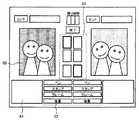
図21は、ステップS190の編集時にタブレットディスプレイ13に表示される編集画面の具体例を示す図であって、画像取扱設定において設定された撮影画像の評価に対応した表示がなされた編集画面の具体例を示す図である。 FIG. 21 is a diagram showing a specific example of the edit screen displayed on the tablet display 13 at the time of editing in step S190, and is a specific example of the edit screen on which display corresponding to the evaluation of the captured image set in the image handling setting is made. It is a figure which shows an example.
図21を参照して、編集画面は、編集対象である撮影画像を表示して撮影画像に実際に編集入力を行なうための描画領域80と、撮影画像に編集入力するための装飾画像である編集用画像を選択するための選択領域81と、編集対象とする撮影画像を切換えるためのボタンや、編集を行なう機能を選択するための「ペン」「スタンプ」「フレーム」などの機能選択ボタンや、入力した画像を消すための「けしごむ」(図示せず)、入力操作を1つ前の状態に戻すための「ひとつもどる」(図示せず)、画像入力を最初からやり直すための「はじめから」(図示せず)などの処理選択ボタンを表示する選択ボタン表示領域82と、描画領域80に表示させて編集対象とすることのできる予め選択された複数の撮影画像を選択可能に表示する編集画像選択領域83とを含んで構成される。 Referring to FIG. 21, the editing screen displays a photographed image to be edited, a
図21に示される編集画面おいて、描画領域80、選択領域81、および選択ボタン表示領域82に表示される選択ボタンは、2つのタッチペン14で別々に編集操作できるように対で2画面構成となっている。このように画面構成されるで、複数のユーザ6で編集プレイを楽しむことができる。それぞれのタッチペン14は2画面のそれぞれに対応する。処理の説明する際、2画面構成の内の片方の画面を用いるが、もう一方の画面においても同様の処理がなされる。言うまでもなく、編集画面の構成は1画面構成または2画面以上の複数の画面構成であってもよいし、タッチペン14も1本または2本以上で構成されていても構わない。 In the editing screen shown in FIG. 21, the selection buttons displayed in the
編集処理中には、撮影された画像と編集入力された編集用画像とはそれぞれ別の画層(レイヤ)に展開され、タブレットディスプレイ13上にそれら画層が重ねて表示される。それぞれの画層のどちらが上に表示されるかは、用途により設定されている。たとえば、編集入力された画像を撮影された画像の前景画像とする場合には、編集入力された画像が上の画層となる。さらに編集入力された画像は、スタンプ画像の層、フレーム画像の層など、それぞれ複数の画層で構成されていてもよい。 During the editing process, the captured image and the editing input image are developed on different layers, and the layers are displayed on the tablet display 13 in an overlapping manner. Which of the layers is displayed above is set according to the application. For example, when the edited and input image is used as the foreground image of the captured image, the edited and input image becomes the upper layer. Further, the edited and input image may be composed of a plurality of layers such as a stamp image layer and a frame image layer.
図21に示される編集画面において、ユーザ6は、編集画像選択領域83に表示される複数の撮影画像の中から編集対象とする撮影画像を選択してタッチペン14でタッチする。さらに、選択ボタン表示領域82に表示される機能選択ボタンの中から編集処理で使用するツールに該当する機能選択ボタンをタッチペン14でタッチする。すると、描画領域80に編集対象とする撮影画像が表示され、選択領域81に選択されたツールで使用可能な編集用画像が表示されて、該編集用画像の色、柄、大きさなどが選択できる。そして、描画領域80に表示された編集対象とする撮影画像に対して、編集用画像を用いて編集入力を行なうことができる。 On the editing screen shown in FIG. 21, the
さらに、図21に示される編集画面の編集画像選択領域83では、上述の画像取扱設定で設定された評価に応じて撮影画像が表示される。より具体的には、設定された取扱順位に応じた順で上から順に並べられるという、評価に対応した優先表示がなされる。または、優先順位が高い撮影画像は他の優先順位の低い画像に比べて大きく表示する表示方法や、優先順位の低い画像の彩度を下げグレーにする表示方法など、撮影画像に設定された評価がユーザ6にわかるような表示方法がなされる。 Furthermore, in the edit
編集画面においてこのような表示がなされることで、先に設定された撮影画像の評価が一目で把握できて評価の高いものを見分けやすく、気に入った撮影画像を編集対象画像として優先的に編集しやすくなり、編集における操作性が向上して編集が容易になる。 With this display on the editing screen, you can easily see the evaluation of the previously set shot image and easily identify the one with the highest evaluation, and you can preferentially edit your favorite shot image as the image to be edited. This facilitates editing, improving operability in editing and facilitating editing.
[印刷画像取扱設定]
上述のステップS195における印刷画像取扱設定について、具体的に説明する。ステップS195では、印刷画像取扱設定として、印刷対象とする画像の選択と共に、印刷対象とする画像の評価である利用形態の再設定あるいは変更を行なう。[Print image handling settings]
The print image handling setting in step S195 described above will be specifically described. In
ステップS335やステップS435の画像取扱設定時に評価が低く設定されていた場合であっても、その撮影画像に対して編集入力が上手にできた場合など、撮影時と編集後とでは画像の評価が変動することもあり得る。そのため、ステップS195の印刷画像設定では、通常の印刷で印刷する合成画像と、余白などに「おまけ画像」として印刷する合成画像とを取替えることができるようにしておくなど、評価の1つとして画像に設定された利用形態を印刷前に変更あるいは再設定可能とする。 Even if the evaluation is set low at the time of setting the image handling in step S335 or step S435, the evaluation of the image is performed at the time of shooting and after the editing, such as when the editing input is successfully made for the captured image. It can also fluctuate. Therefore, in the print image setting in step S195, an image is one of the evaluations such that the composite image to be printed by normal printing and the composite image to be printed as a “bonus image” in the margin can be replaced. The usage mode set in can be changed or reset before printing.
また、利用形態には、どのように印刷されるかだけでなく、どのように出力されるかが含まれ、ステップS195の印刷画像設定では、どのように印刷されるかだけでなく、どのように出力されるかが設定されてもよい。たとえば、印刷するだけでなく携帯電話などに合成画像を送信できるような写真自動販売機の場合、利用形態としてどの合成画像を携帯電話に送信するのか設定できてもよい。 The usage pattern includes not only how the image is printed but also how it is output. In the print image setting in step S195, not only how the image is printed but also how it is printed. It may be set whether or not to be output. For example, in the case of a photo vending machine that can send a composite image to a mobile phone or the like as well as print, it may be possible to set which composite image is sent to the mobile phone as a usage form.
さらに、利用形態として、印刷する画像の大きさや位置などが評価に対応して設定されてもよい。たとえば、評価の高い画像は大きく印刷されたり、目立つ位置に印刷されたり設定されてもよい。 Furthermore, as a usage form, the size and position of an image to be printed may be set corresponding to the evaluation. For example, a highly evaluated image may be printed large or printed at a conspicuous position.
このようにして、印刷対象とすることのできる合成画像について、撮影画像に設定された評価に応じて利用形態を設定することができるため、より顧客の満足する印刷シールを作成することができる。このため、顧客満足が向上する。 In this way, since the usage mode can be set according to the evaluation set for the photographed image with respect to the composite image that can be the print target, it is possible to create a print sticker that satisfies the customer. This improves customer satisfaction.
さらに、上述の写真自動販売機のコンピュータ装置101の制御方法を、プログラムとして提供することもできる。このようなプログラムは、コンピュータに付属するフレキシブルディスク、CD−ROM(Compact Disc-Read Only Memory)、ROM(Read Only Memory)、RAM(Random Access Memory)、DVD−ROM(Digital Versatile Disc-Read Only Memory)およびメモリカードなどのコンピュータ読取り可能な記録媒体にて記録させて、プログラム製品として提供することもできる。あるいは、コンピュータに内蔵するハードディスクなどの記録媒体にて記録させて、プログラムを提供することもできる。また、ネットワークを介したダウンロードによって、プログラムを提供することもできる。 Further, the above-described method for controlling the computer device 101 of the photo vending machine can be provided as a program. Such programs include a flexible disk attached to the computer, a CD-ROM (Compact Disc-Read Only Memory), a ROM (Read Only Memory), a RAM (Random Access Memory), a DVD-ROM (Digital Versatile Disc-Read Only Memory). ) And a computer-readable recording medium such as a memory card, and can be provided as a program product. Alternatively, the program can be provided by being recorded on a recording medium such as a hard disk built in the computer. A program can also be provided by downloading via a network.
提供されるプログラム製品は、ハードディスクなどのプログラム格納部にインストールされて実行される。なお、プログラム製品は、プログラム自体と、プログラムが記録された記録媒体とを含む。 The provided program product is installed in a program storage unit such as a hard disk and executed. The program product includes the program itself and a recording medium on which the program is recorded.
今回開示された実施の形態はすべての点で例示であって制限的なものではないと考えられるべきである。本発明の範囲は上記した説明ではなくて特許請求の範囲によって示され、特許請求の範囲と均等の意味および範囲内でのすべての変更が含まれることが意図される。 The embodiment disclosed this time should be considered as illustrative in all points and not restrictive. The scope of the present invention is defined by the terms of the claims, rather than the description above, and is intended to include any modifications within the scope and meaning equivalent to the terms of the claims.
1 筐体、2,2a,2b 編集筐体、3 撮影空間、4,4a,4b 編集空間、5 背景部、6 ユーザ、7 撮影中ランプ、8 プリント取出口、9,9a,9b 印刷ランプ、10 用紙切れランプ、11 エラーランプ、12 プリンタ、13,13a,13b タブレットディスプレイ、14,14a〜14d タッチペン、15 プリント案内部、18,18a〜18f 照明部、20 レリーズスイッチ、21 カメラ、22 ライブモニタ、23,23a〜23f スピーカ、24 タッチパネルディスプレイ、26 コイン投入口、27 コイン返却口、28 フロントドア、29,29a〜29h フラッシュ、30 照明装置、31 電源スイッチ、40,40a〜40c サイドカーテン、41 ロールスクリーン、42 巻取装置、50,50a〜50g 拡散板、51,51a〜51d 反射板、52 透過板、80,81,83 領域、101,101a,101b コンピュータ装置、102 制御部、103 電源制御部、104 UPS、105 サービスパネル、106 フラッシュ制御部、107 コイン制御部、110 通信端末、401a,401b 編集部。 1 housing, 2, 2a, 2b editing housing, 3 shooting space, 4, 4a, 4b editing space, 5 background section, 6 user, 7 shooting lamp, 8 print outlet, 9, 9a, 9b printing lamp, 10 Out of paper lamp, 11 Error lamp, 12 Printer, 13, 13a, 13b Tablet display, 14, 14a-14d Touch pen, 15 Print guide section, 18, 18a-18f Illumination section, 20 Release switch, 21 Camera, 22 Live monitor , 23, 23a-23f Speaker, 24 Touch panel display, 26 Coin slot, 27 Coin return slot, 28 Front door, 29, 29a-29h Flash, 30 Lighting device, 31 Power switch, 40, 40a-40c Side curtain, 41 Roll screen, 42 winding device, 0, 50a-50g Diffuser plate, 51, 51a-51d Reflector plate, 52 Transmitter plate, 80, 81, 83 area, 101, 101a, 101b Computer device, 102 Control unit, 103 Power supply control unit, 104 UPS, 105
Claims (11)
Translated fromJapanese前記被写体を照明する照明手段とを備え、
前記照明手段は、前記撮影手段よりも上方に設置されて、前記撮影手段に相対した前記被写体を前記撮影手段側から前記撮影手段の撮影方向と略平行に照明する第1の照明手段を含み、
前記第1の照明手段は、
箱型の筐体と、
前記箱型の筐体内部の光源と、
前記光源より発光された光を前記被写体に照射する照射面とを含み、
前記照射面は、
前記撮影手段に対して略鉛直上方に位置し、前記撮影手段に相対した前記被写体の顔周辺を照射するための顔照明部と、
前記顔照明部の両横および上方に前記顔照明部を囲んで位置し、前記撮影手段に相対した前記被写体の顔周囲の頭髪周辺を照射するための髪照明部とを含んで構成される、写真自動販売機。Photographing means for photographing the subject;
Illumination means for illuminating the subject,
The illumination handstage, the captured is installed above the unit,comprises a first illuminating means for photographing direction substantially parallel to the illumination of the imaging means the subject relative to the imaging unit from the imaging means side ,
The first illumination means includes
A box-shaped housing;
A light source inside the box-shaped housing;
An irradiation surface for irradiating the subject with light emitted from the light source,
The irradiated surface is
A face illuminator for illuminating the periphery of the subject's face thatis positioned substantially vertically above the photographing means and is opposed to the photographing means;
A hairillumination unit that is located on both sides and above the face illumination unit so as to surround the face illumination unit and irradiatesaround the hair around theface of the subjectopposite to the photographing unit , Photo vending machine.
前記第1の照明手段、前記第2の照明手段、および前記撮影手段は、前記撮影手段の撮影方向に略直交する方向に、前記撮影手段を谷とする凹型を構成する、請求項1〜6のいずれかに記載の写真自動販売機。The illumination handstage is placed lower than the imaging meansfurther includes a second illumination means for illuminating the subject relative to the imaging unit from the imaging means side,
Said first illumination means, the second illumination means, and said imaging means, in a direction substantially perpendicular to the photographing direction of the photographing means, constitutes a concave to a valley of the imaging unit, according to claim 1 to6 A photo vending machine as described in any of the above.
前記被写体を照明する照明手段と、
ユーザから前記照明手段における照明方法の選択を受付ける選択手段とを備え、
前記照明手段は、前記撮影手段よりも上方に設置されて、前記撮影手段に相対した前記被写体を前記撮影手段側から前記撮影手段の撮影方向と略平行に照明する第1の照明手段を含み、
前記第1の照明手段は、
箱型の筐体と、
前記箱型の筐体内部の光源と、
前記光源より発光された光を前記被写体に照射する照射面とを含み、
前記照射面は、
前記撮影手段に対して略鉛直上方に位置し、前記撮影手段に相対した前記被写体の顔周辺を照射するための顔照明部と、
前記顔照明部の両横および上方に前記顔照明部を囲んで位置し、前記撮影手段に相対した前記被写体の顔周囲の頭髪周辺を照射するための髪照明部とを含んで構成される写真自動販売機の制御方法であって、
前記選択手段において、前記ユーザから照明方法の選択を受付ける選択ステップと、
前記選択された照明方法で前記被写体を照明するよう、前記照明手段の設定を前記選択された照明方法に対応する設定とする制御を行なう制御ステップと、
前記照明方法で照明された下で前記被写体を前記撮影手段において撮影する撮影ステップとを備える、写真自動販売機の制御方法。Photographing means for photographing the subject;
Illumination means for illuminating the subject;
Selecting means for receiving selection of a lighting method in the lighting means from a user,
The illumination handstage, the captured is installed above the unit,comprises a first illuminating means for photographing direction substantially parallel to the illumination of the imaging means the subject relative to the imaging unit from the imaging means side ,
The first illumination means includes
A box-shaped housing;
A light source inside the box-shaped housing;
An irradiation surface for irradiating the subject with light emitted from the light source,
The irradiated surface is
A face illuminator for illuminating the periphery of the subject's face thatis positioned substantially vertically above the photographing means and is opposed to the photographing means;
A photograph includinga hairillumination unit that is positioned on both sides and above the face illumination unit so as to surround the face illumination unit and irradiatesaround the hair around theface of the subjectfacing thephotographing means. Vending machine control method,
In the selection means, a selection step of accepting a selection of a lighting method from the user;
A control stepfor controlling the setting of the illumination meansto be a setting corresponding to the selected illumination method so as to illuminate the subject with theselected illumination method ;
A method for controlling a photo vending machine comprising: a photographing step of photographing the subject by the photographing means under illumination by the illumination method.
前記被写体を照明する照明手段と、
ユーザから前記照明手段における照明方法の選択を受付ける選択手段とを備え、
前記照明手段は、前記撮影手段よりも上方に設置されて、前記撮影手段に相対した前記被写体を前記撮影手段側から前記撮影手段の撮影方向と略平行に照明する第1の照明手段を含み、
前記第1の照明手段は、
箱型の筐体と、
前記箱型の筐体内部の光源と、
前記光源より発光された光を前記被写体に照射する照射面とを含み、
前記照射面は、
前記撮影手段に対して略鉛直上方に位置し、前記撮影手段に相対した前記被写体の顔周辺を照射するための顔照明部と、
前記顔照明部の両横および上方に前記顔照明部を囲んで位置し、前記撮影手段に相対した前記被写体の顔周囲の頭髪周辺を照射するための髪照明部とを含んで構成される写真自動販売機の制御方法をコンピュータに実行させるプログラムであって、
前記選択手段において、前記ユーザから照明方法の選択を受付ける選択ステップと、
前記選択された照明方法で前記被写体を照明するよう、前記照明手段の設定を前記選択された照明方法に対応する設定とする制御を行なう制御ステップと、
前記照明方法で照明された下で前記被写体を前記撮影手段において撮影する撮影ステップとを実行させる、写真自動販売機の制御プログラム。Photographing means for photographing the subject;
Illumination means for illuminating the subject;
Selecting means for receiving selection of a lighting method in the lighting means from a user,
The illumination handstage, the captured is installed above the unit,comprises a first illuminating means for photographing direction substantially parallel to the illumination of the imaging means the subject relative to the imaging unit from the imaging means side ,
The first illumination means includes
A box-shaped housing;
A light source inside the box-shaped housing;
An irradiation surface for irradiating the subject with light emitted from the light source,
The irradiated surface is
A face illuminator for illuminating the periphery of the subject's face thatis positioned substantially vertically above the photographing means and is opposed to the photographing means;
A photograph includinga hairillumination unit that is positioned on both sides and above the face illumination unit so as to surround the face illumination unit and irradiatesaround the hair around theface of the subjectfacing thephotographing means. A program for causing a computer to execute a control method of a vending machine,
In the selection means, a selection step of accepting a selection of a lighting method from the user;
A control stepfor controlling the setting of the illumination meansto be a setting corresponding to the selected illumination method so as to illuminate the subject with theselected illumination method ;
A control program for a photo vending machine that executes a photographing step of photographing the subject by the photographing means under illumination by the illumination method.
Priority Applications (1)
| Application Number | Priority Date | Filing Date | Title |
|---|---|---|---|
| JP2004049905AJP4318565B2 (en) | 2004-02-25 | 2004-02-25 | Photo vending machine, photo vending machine control method, and photo vending machine control program |
Applications Claiming Priority (1)
| Application Number | Priority Date | Filing Date | Title |
|---|---|---|---|
| JP2004049905AJP4318565B2 (en) | 2004-02-25 | 2004-02-25 | Photo vending machine, photo vending machine control method, and photo vending machine control program |
Publications (2)
| Publication Number | Publication Date |
|---|---|
| JP2005241839A JP2005241839A (en) | 2005-09-08 |
| JP4318565B2true JP4318565B2 (en) | 2009-08-26 |
Family
ID=35023651
Family Applications (1)
| Application Number | Title | Priority Date | Filing Date |
|---|---|---|---|
| JP2004049905AExpired - LifetimeJP4318565B2 (en) | 2004-02-25 | 2004-02-25 | Photo vending machine, photo vending machine control method, and photo vending machine control program |
Country Status (1)
| Country | Link |
|---|---|
| JP (1) | JP4318565B2 (en) |
Families Citing this family (3)
| Publication number | Priority date | Publication date | Assignee | Title |
|---|---|---|---|---|
| JP5970026B2 (en)* | 2014-07-04 | 2016-08-17 | フリュー株式会社 | Photo sticker creation device |
| JP6984386B2 (en)* | 2017-12-19 | 2021-12-17 | 大日本印刷株式会社 | Shooting device |
| US11947244B2 (en) | 2020-02-18 | 2024-04-02 | Nec Corporation | Gate apparatus |
- 2004
- 2004-02-25JPJP2004049905Apatent/JP4318565B2/ennot_activeExpired - Lifetime
Also Published As
| Publication number | Publication date |
|---|---|
| JP2005241839A (en) | 2005-09-08 |
Similar Documents
| Publication | Publication Date | Title |
|---|---|---|
| JP2004349959A (en) | Photographing equipment, print sheet, control method for photographing equipment, control program for photographing equipment, and computer readable recording medium having the control program recorded therein | |
| JP2005079662A (en) | Image editing method in photograph vending machine, photograph vending machine, and image editing program | |
| JP2005025027A (en) | Photograph vending machine and pose guiding method therefor | |
| JP2006106523A (en) | Photograph vending machine | |
| JP4516768B2 (en) | Photography method in photo vending machine, photo vending machine, and control program for photo vending machine | |
| JP2004357018A (en) | Photograph vending machine and photograph providing method in photograph vending machine | |
| JP4318565B2 (en) | Photo vending machine, photo vending machine control method, and photo vending machine control program | |
| JP2006072045A (en) | Automatic photographing device | |
| JP4301967B2 (en) | Photo vending machine, photo vending machine control method, and photo vending machine control program | |
| JP4301966B2 (en) | Photo vending machine, photo vending machine control method, and photo vending machine control program | |
| JP2003241296A (en) | Automatic vending method for photograph seal, equipment for the same, seal paper unit, and photographic seal sheet | |
| JP2006072418A (en) | Image composition method and device | |
| JP2006041595A (en) | Photographic device, control method of photographic device, and control program of photographic device | |
| JP4405344B2 (en) | Photo sticker creation device | |
| JP3524088B1 (en) | Image input method, image input program, and photo vending machine | |
| JP2005070955A (en) | Picture vending machine and picture photographing method in picture vending machine | |
| JP3542352B1 (en) | Photo taking method in photo vending machine, photo vending machine, and control program for photo vending machine | |
| JP5428245B2 (en) | Photo editing device | |
| JP3919755B2 (en) | Image input method, image input program, photo vending machine control method, photo vending machine, and image setting program in image printing apparatus | |
| JP4640156B2 (en) | Photography editing method and apparatus | |
| JP2020112638A (en) | Photography game machine, control method, and program | |
| JP3082547U (en) | Photo sticker vending machine and photo sticker sheet | |
| JP2006010933A (en) | Photograph vending machine and photography method | |
| JP2006106296A (en) | Photograph automatic vending machine | |
| JP2006058674A (en) | Automatic photographing apparatus |
Legal Events
| Date | Code | Title | Description |
|---|---|---|---|
| A621 | Written request for application examination | Free format text:JAPANESE INTERMEDIATE CODE: A621 Effective date:20070115 | |
| A977 | Report on retrieval | Free format text:JAPANESE INTERMEDIATE CODE: A971007 Effective date:20081212 | |
| A131 | Notification of reasons for refusal | Free format text:JAPANESE INTERMEDIATE CODE: A131 Effective date:20090127 | |
| A521 | Request for written amendment filed | Free format text:JAPANESE INTERMEDIATE CODE: A523 Effective date:20090324 | |
| TRDD | Decision of grant or rejection written | ||
| A01 | Written decision to grant a patent or to grant a registration (utility model) | Free format text:JAPANESE INTERMEDIATE CODE: A01 Effective date:20090519 | |
| A01 | Written decision to grant a patent or to grant a registration (utility model) | Free format text:JAPANESE INTERMEDIATE CODE: A01 | |
| A61 | First payment of annual fees (during grant procedure) | Free format text:JAPANESE INTERMEDIATE CODE: A61 Effective date:20090526 | |
| FPAY | Renewal fee payment (event date is renewal date of database) | Free format text:PAYMENT UNTIL: 20120605 Year of fee payment:3 | |
| R150 | Certificate of patent or registration of utility model | Ref document number:4318565 Country of ref document:JP Free format text:JAPANESE INTERMEDIATE CODE: R150 Free format text:JAPANESE INTERMEDIATE CODE: R150 | |
| FPAY | Renewal fee payment (event date is renewal date of database) | Free format text:PAYMENT UNTIL: 20120605 Year of fee payment:3 | |
| FPAY | Renewal fee payment (event date is renewal date of database) | Free format text:PAYMENT UNTIL: 20120605 Year of fee payment:3 | |
| FPAY | Renewal fee payment (event date is renewal date of database) | Free format text:PAYMENT UNTIL: 20130605 Year of fee payment:4 | |
| R250 | Receipt of annual fees | Free format text:JAPANESE INTERMEDIATE CODE: R250 | |
| FPAY | Renewal fee payment (event date is renewal date of database) | Free format text:PAYMENT UNTIL: 20130605 Year of fee payment:4 | |
| FPAY | Renewal fee payment (event date is renewal date of database) | Free format text:PAYMENT UNTIL: 20130605 Year of fee payment:4 | |
| FPAY | Renewal fee payment (event date is renewal date of database) | Free format text:PAYMENT UNTIL: 20130605 Year of fee payment:4 | |
| R250 | Receipt of annual fees | Free format text:JAPANESE INTERMEDIATE CODE: R250 | |
| R250 | Receipt of annual fees | Free format text:JAPANESE INTERMEDIATE CODE: R250 | |
| S531 | Written request for registration of change of domicile | Free format text:JAPANESE INTERMEDIATE CODE: R313531 | |
| R350 | Written notification of registration of transfer | Free format text:JAPANESE INTERMEDIATE CODE: R350 | |
| R250 | Receipt of annual fees | Free format text:JAPANESE INTERMEDIATE CODE: R250 | |
| R250 | Receipt of annual fees | Free format text:JAPANESE INTERMEDIATE CODE: R250 | |
| R250 | Receipt of annual fees | Free format text:JAPANESE INTERMEDIATE CODE: R250 | |
| R250 | Receipt of annual fees | Free format text:JAPANESE INTERMEDIATE CODE: R250 | |
| S111 | Request for change of ownership or part of ownership | Free format text:JAPANESE INTERMEDIATE CODE: R313113 | |
| R350 | Written notification of registration of transfer | Free format text:JAPANESE INTERMEDIATE CODE: R350 | |
| R250 | Receipt of annual fees | Free format text:JAPANESE INTERMEDIATE CODE: R250 | |
| R250 | Receipt of annual fees | Free format text:JAPANESE INTERMEDIATE CODE: R250 | |
| S111 | Request for change of ownership or part of ownership | Free format text:JAPANESE INTERMEDIATE CODE: R313114 | |
| R360 | Written notification for declining of transfer of rights | Free format text:JAPANESE INTERMEDIATE CODE: R360 | |
| R250 | Receipt of annual fees | Free format text:JAPANESE INTERMEDIATE CODE: R250 | |
| R360 | Written notification for declining of transfer of rights | Free format text:JAPANESE INTERMEDIATE CODE: R360 | |
| R371 | Transfer withdrawn | Free format text:JAPANESE INTERMEDIATE CODE: R371 | |
| S111 | Request for change of ownership or part of ownership | Free format text:JAPANESE INTERMEDIATE CODE: R313114 | |
| R350 | Written notification of registration of transfer | Free format text:JAPANESE INTERMEDIATE CODE: R350 | |
| R250 | Receipt of annual fees | Free format text:JAPANESE INTERMEDIATE CODE: R250 | |
| R250 | Receipt of annual fees | Free format text:JAPANESE INTERMEDIATE CODE: R250 | |
| EXPY | Cancellation because of completion of term |