JP4318421B2 - Multiaxial bone screw assembly - Google Patents
Multiaxial bone screw assemblyDownload PDFInfo
- Publication number
- JP4318421B2 JP4318421B2JP2001519829AJP2001519829AJP4318421B2JP 4318421 B2JP4318421 B2JP 4318421B2JP 2001519829 AJP2001519829 AJP 2001519829AJP 2001519829 AJP2001519829 AJP 2001519829AJP 4318421 B2JP4318421 B2JP 4318421B2
- Authority
- JP
- Japan
- Prior art keywords
- assembly
- head
- bone
- crown
- opening
- Prior art date
- Legal status (The legal status is an assumption and is not a legal conclusion. Google has not performed a legal analysis and makes no representation as to the accuracy of the status listed.)
- Expired - Lifetime
Links
- 210000000988bone and boneAnatomy0.000titleclaimsabstractdescription130
- 230000006835compressionEffects0.000claimsabstractdescription12
- 238000007906compressionMethods0.000claimsabstractdescription12
- 238000004873anchoringMethods0.000claimsdescription6
- 230000013011matingEffects0.000claims1
- 230000000149penetrating effectEffects0.000claims1
- 238000000034methodMethods0.000description8
- 239000000463materialSubstances0.000description6
- 239000007943implantSubstances0.000description4
- 230000000399orthopedic effectEffects0.000description4
- 210000004705lumbosacral regionAnatomy0.000description2
- 238000012986modificationMethods0.000description2
- 230000004048modificationEffects0.000description2
- 206010069689Spinal column injuryDiseases0.000description1
- RTAQQCXQSZGOHL-UHFFFAOYSA-NTitaniumChemical compound[Ti]RTAQQCXQSZGOHL-UHFFFAOYSA-N0.000description1
- 206010052428WoundDiseases0.000description1
- 208000027418Wounds and injuryDiseases0.000description1
- 230000005856abnormalityEffects0.000description1
- 238000005452bendingMethods0.000description1
- 239000000560biocompatible materialSubstances0.000description1
- 238000004891communicationMethods0.000description1
- 230000008602contractionEffects0.000description1
- 238000005516engineering processMethods0.000description1
- 230000002708enhancing effectEffects0.000description1
- 230000007257malfunctionEffects0.000description1
- 230000001737promoting effectEffects0.000description1
- 238000010079rubber tappingMethods0.000description1
- 230000000087stabilizing effectEffects0.000description1
- 229910001220stainless steelInorganic materials0.000description1
- 239000010935stainless steelSubstances0.000description1
- 238000001356surgical procedureMethods0.000description1
- 210000000115thoracic cavityAnatomy0.000description1
- 210000001519tissueAnatomy0.000description1
- 229910052719titaniumInorganic materials0.000description1
- 239000010936titaniumSubstances0.000description1
Images


Classifications
- A—HUMAN NECESSITIES
- A61—MEDICAL OR VETERINARY SCIENCE; HYGIENE
- A61B—DIAGNOSIS; SURGERY; IDENTIFICATION
- A61B17/00—Surgical instruments, devices or methods
- A61B17/56—Surgical instruments or methods for treatment of bones or joints; Devices specially adapted therefor
- A61B17/58—Surgical instruments or methods for treatment of bones or joints; Devices specially adapted therefor for osteosynthesis, e.g. bone plates, screws or setting implements
- A61B17/68—Internal fixation devices, including fasteners and spinal fixators, even if a part thereof projects from the skin
- A61B17/70—Spinal positioners or stabilisers, e.g. stabilisers comprising fluid filler in an implant
- A61B17/7001—Screws or hooks combined with longitudinal elements which do not contact vertebrae
- A61B17/7035—Screws or hooks, wherein a rod-clamping part and a bone-anchoring part can pivot relative to each other
- A61B17/7037—Screws or hooks, wherein a rod-clamping part and a bone-anchoring part can pivot relative to each other wherein pivoting is blocked when the rod is clamped
- A—HUMAN NECESSITIES
- A61—MEDICAL OR VETERINARY SCIENCE; HYGIENE
- A61B—DIAGNOSIS; SURGERY; IDENTIFICATION
- A61B17/00—Surgical instruments, devices or methods
- A61B17/56—Surgical instruments or methods for treatment of bones or joints; Devices specially adapted therefor
- A61B17/58—Surgical instruments or methods for treatment of bones or joints; Devices specially adapted therefor for osteosynthesis, e.g. bone plates, screws or setting implements
- A61B17/68—Internal fixation devices, including fasteners and spinal fixators, even if a part thereof projects from the skin
- A61B17/70—Spinal positioners or stabilisers, e.g. stabilisers comprising fluid filler in an implant
- A61B17/7001—Screws or hooks combined with longitudinal elements which do not contact vertebrae
- A61B17/7032—Screws or hooks with U-shaped head or back through which longitudinal rods pass
- A—HUMAN NECESSITIES
- A61—MEDICAL OR VETERINARY SCIENCE; HYGIENE
- A61B—DIAGNOSIS; SURGERY; IDENTIFICATION
- A61B17/00—Surgical instruments, devices or methods
- A61B2017/00831—Material properties
- A61B2017/00858—Material properties high friction or non-slip
- A—HUMAN NECESSITIES
- A61—MEDICAL OR VETERINARY SCIENCE; HYGIENE
- A61B—DIAGNOSIS; SURGERY; IDENTIFICATION
- A61B90/00—Instruments, implements or accessories specially adapted for surgery or diagnosis and not covered by any of the groups A61B1/00 - A61B50/00, e.g. for luxation treatment or for protecting wound edges
- A61B90/03—Automatic limiting or abutting means, e.g. for safety
- A61B2090/037—Automatic limiting or abutting means, e.g. for safety with a frangible part, e.g. by reduced diameter
Landscapes
- Health & Medical Sciences (AREA)
- Orthopedic Medicine & Surgery (AREA)
- Life Sciences & Earth Sciences (AREA)
- Neurology (AREA)
- Surgery (AREA)
- Heart & Thoracic Surgery (AREA)
- General Health & Medical Sciences (AREA)
- Biomedical Technology (AREA)
- Nuclear Medicine, Radiotherapy & Molecular Imaging (AREA)
- Medical Informatics (AREA)
- Molecular Biology (AREA)
- Animal Behavior & Ethology (AREA)
- Engineering & Computer Science (AREA)
- Public Health (AREA)
- Veterinary Medicine (AREA)
- Surgical Instruments (AREA)
- Control Of Motors That Do Not Use Commutators (AREA)
- Materials For Medical Uses (AREA)
- Pharmaceuticals Containing Other Organic And Inorganic Compounds (AREA)
Abstract
Description
Translated fromJapanese【0001】
【発明の分野】
本発明は、骨接合法及びその他の整形外科的方法にて使用される装置及びインプラントに関する。具体的には、本発明は、骨組織に沿って伸びる細長い部材に対する多数の角度方向を実現することのできる底部装填型骨アンカー組立体を対象とするものである。
【0002】
【発明の技術】
骨、特に、長骨及び脊柱の損傷又は機能不全を矯正し且つ安定化させるため、幾つかの技術及び装置が開発されている。1つの型式の装置において、曲げ可能なロッドのような細長い部材が骨の長さに沿って長手方向に配置されている。脊柱への適用例において、該ロッドは、装具を取り付ける特定の領域にて脊柱の通常の曲率に相応するように曲がっていることが好ましい。例えば、脊柱の胸椎領域に対する通常の後湾曲率又は腰椎領域に対する前湾曲率を形成するようにロッドを曲げることができる。かかる装置によれば、ロッドは、多数の固定要素を介して脊柱の長さに沿って色々な椎骨に係合可能である。椎骨及びその他の骨の特定の部分に係合する形態とされた多岐に亙る固定要素を提供することができる。例えば、かかる固定要素の1つは、椎骨の積層体に係合する形態とされたフックである。別の極めて一般的な固定要素は、椎骨又はその他の骨の色々な部分にねじ込むことのできるねじである。
【0003】
曲げ可能なロッドを利用する1つの典型的な脊柱方法において、ロッドは、脊柱又は棘突起の両側部に配置される。幾つかの椎骨体の一部分内に、極めて多くの場合、これら椎骨の茎内に複数の骨ねじがねじ込まれる。ロッドは、脊柱に対し矯正力及び安定化力を付与し得るようにこれら複数の骨ねじに定着されている。
【0004】
ロッド型式の脊柱固定装置の一例は、メドトロニック・ソファモール・ダネック(Medtronic Sofamor Danek)インコーポレーテッドから販売されているTSRH(登録商標名)脊柱装置である。このTSRH(登録商標名)装置は、細長いロッドと、多岐に亙るフック、ねじ及びボルトとを備えており、これらは、全て脊柱の全体に亙って分節状構造体を形成し得るような形態とされている。TSRH(登録商標名)装置の1つの面において、脊柱−ロッドはアイボルトを介して色々な椎骨固定要素に接続されている。この形態において、固定要素は、ロッドの横方向に隣接して脊柱ロッドに係合する。TSRH(登録商標名)装置の別の面において、角度可変ねじがアイボルトを介して脊柱ロッドに係合されている。この角度可変ねじは、脊柱ロッドの面に対し平行な単一の面内にて骨ねじが枢動するのを許容する。この角度可変ねじの詳細は、本発明の譲受人が所有する、スターリン(Sutterlin)らへの米国特許第5,261,909号に見ることができる。TSRH(登録商標名)装置により実現される1つの目的は、外科医が脊柱フック又は骨ねじのような椎骨の固定要素を適正な身体部分の位置にて脊柱に取り付けることができることである。TSRH(登録商標名)装置は、また、外科医が曲がった脊柱ロッドを最終的に締め付けるために固定要素の各々に容易に係合させることを許容する。
【0005】
別のロッド型式の固定装置は、メドトロニック・ソファモール・ダネック・インコーポレーテッドから販売されているコトレル−デュボセット(Cotrel−Dubosset)/CD(登録商標名)スピナル・システム(Spinal system)である。TSRH(登録商標名)装置と同様に、CD(登録商標名)装置は、細長いロッドと脊柱とを係合させる多岐に亙る固定要素を提供する。CD(登録商標名)装置の1つの面において、該固定要素自体がその内部に脊柱ロッドが受け入れられるスロットを画成する本体を備えている。該スロットは、ロッドを固定要素の本体内にクランプ止めし得るようにねじ付きプラグが係合するねじ付き穴を有している。CD(登録商標名)装置は、この「後方開放」形態によるフック及び骨ねじを備えている。この技術の詳細は、コトレル(Cotrel)への米国特許第5,005,562号に見ることができる。このCD(登録商標名)装置のこの特徴の1つの有利な点は、固定要素が細長いロッドの真下に配置される点である。このことは、インプラント構造体の全体の大きさを小さくするのに役立ち且つ周囲の組織への創傷を最小にするものである。
【0006】
他方、CD(登録商標名)装置のこれらの固定要素は、ロッドに対する角度可変位置を実現し得るように脊柱ロッドの周りでのみ枢動することができる。この制限された相対的な角度位置の範囲は多くの脊柱の異常に許容可能ではあるが、多くのその他の事例は、例えば、脊柱ロッドに対する骨ねじのより独創的な方向決めを必要とする。この問題点の幾つかの面は、米国特許第5,261,909号に記載されたように、TSRH(登録商標名)装置の可変角度ねじにより対処されている。しかし、脊柱ロッドに対する多数の面内で角度方向を設定することのできる骨ねじが必要とされている。好ましくは、この骨ねじは脊柱ロッドに対する色々な三次元的方向の設定が可能であるようにする。この型式のねじは、ポリアキシャル又はマルチアキシャル骨ねじと称されている。
【0007】
色々なポリアキシャルねじの設計にてこの問題点に対処しようと試みるものもある。例えば、バード(Byrd)らへの米国特許第5,466,237号において、骨ねじの頂部に球状突起を有する骨ねじが記載されている。外ねじ付き受入れ部材が骨ねじ及び脊柱ロッドを球状突起の頂部にて支持している。ロッドに対する骨ねじの色々な角度方向に対応すべく脊柱ロッドを球状突起に押し付けるべく外側ナットを受入れ部材上に締め付ける。この特定の解決策は、利用する構成要素が最小限で済むが、ロッドに対する骨ねじの固定の確実さに欠ける。換言すれば、骨ねじの小さい球状突起と脊柱ロッドとの間の係合又は固定は、特に腰椎領域内で装具に脊柱の大きい荷重が加わるとき、容易に分離する。
【0008】
ハームズ(Harms)らへの米国特許第4,946,458号に記載された別の解決法において、球状頭部の骨ねじが受入れ部材の別個の半体内に支持されている。これら半体の底部は止めリングにより共に保持されている。受入れ部材の半体の頂部は、ねじ付き脊柱ロッドにねじ止めされたナットにより骨ねじの周りに圧縮されている。ハームズらによる別の解決策の米国特許第5,207,678号において、受入れ部材が骨ねじの部分球状頭部の周りに撓み可能に接続されている。受入れ部材の両側部における円錐形ナットは受入れ部材を貫通するねじ付きロッドにねじ止めされている。円錐形ナットは互いに向けてねじ止めされるため、受入れ部材が骨ねじの頭部の周りで撓み可能に圧縮して、骨ねじをその可変角度位置にクランプ止めする。2つのハームズらの特許における装置の1つの欠点は、圧縮ナットを受け入れるために脊柱ロッドにねじを設けなければならない点である。ねじ付きロッドは顕著な脊柱荷重を受けたとき、ロッドが弱化し易いことが既知である。更に、米国特許第4,946,458号及び米国特許第5,207,678号に記載された骨ねじの設計は、多数の部品を必要とし、また、骨ねじを完全に固定するためにかなり複雑である。
【0009】
本発明の譲受人が所有する、シャーマン(Sheman)らへの米国特許第5,797,911号に記載された更なる解決策は、U字形のホルダを提供し、頂部にクラウン部材を有する骨締結具に対しこのU字形のホルダの頂部を通じて荷重が加えられる。該ホルダは、クラウン部材の上方で通路内にロッドを受け入れ且つ該ロッドの上方で圧縮部材を受け入れる。圧縮部材がロッド及びクラウン部材に押し付けられてロッドに対する三次元的な多数角度の任意の角度にて締結具をホルダに対して係止する。この解決策は、上述した問題点に対処する点で極めて効果的であることが判明している。しかし、この方法は、締結具の底部装填を許容しない。更に、ホルダは、その他の構造的構成要素を受け入れ得るように幾分、大形である。
【0010】
エリコ(Errico)らへの米国特許第5,733,285号に更なる解決法が記載されており、この場合、ホルダには、テーパー付きで且つコレット付きの部分がその底部に設けられており、この部分内に骨締結具の頭部が挿入される。骨締結具の頭部の周りでコレット付き部分が潰れ係止し得るようにコレット付き部分の周りで下方に摺動するスリーブが設けられる。この装置は、外側の摺動係止機構が存在することから、比較的大形で且つ操作が難しいと考えられる。この装置は、骨締結具の頭部を確実に係止するために、外側スリーブが嵌ること及びコレット、その曲がり且つ潰れ部分の相対的強度に更に依存する。
【0011】
このため、骨アンカーの改良された角度、改良された強度及び多岐に亙る角度方向の任意の角度にて骨アンカーを細長い部材に係合させるために使用される構成要素のプロフィール及び大きさを含む、縮小された寸法を実現する、任意の形態、すなわち平滑面、粗面、ギザギザ付き面とし、更にはねじを設けることさえも可能な細長い部材に容易に且つ確実に係合することのできる、マルチアキシャル骨アンカーが当該技術分野にて依然として必要とされている。
【0012】
【発明の概要】
本発明の1つの実施の形態において、受入れ部材であって、上側開口部分及び下側開口部分と、上側及び下側開口部分と連通して、細長い部材を受け入れ得る形態とされた通路と、下側開口部分の一部分の周りの溝とを画成する上記受入れ部材を有する骨固定組立体が提供される。該組立体は、上面及び下面を有し、下側開口部分内に可動に配置されたクラウン部材と、骨に係合し得る形態とされた下側部分と、下側開口部分よりも小さい頭部を有する骨係合アンカーとを更に備え、該頭部は、クラウン部材の凹状の下面に隣接して下側開口部分内に可動に配置される。該組立体はまた、骨アンカーの頭部よりも小さい開孔を画成する止め部材を更に備えており、該止め部材は、受入れ部材の溝内に少なくとも部分的に収容され且つ骨アンカーの周りで且つその頭部の下方に配置される。
【0013】
本発明の更なる実施の形態、実施例、有利な点及び目的は、本明細書の以下の説明から当該技術分野の当業者に明らかになるであろう。
【0014】
【好ましい実施の形態の説明】
本発明の原理の理解を促進する目的のために、次に、図面に図示した実施の形態に関して説明し、その説明のために特定の用語を使用する。しかし、これにより、本発明の範囲を何ら限定することを意図するものではなく、本明細書に記載した装置の変更及び更なる改変例並びに本明細書に記載した本発明の原理の更なる適用例は、本発明が関係する技術分野の当業者に通常、案出されるものであることを理解すべきである。
【0015】
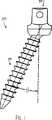
全体として、図1及び図2を参照すると、本発明のマルチアキシャル骨アンカー組立体20の1つの実施の形態が図示されている。図示した実施の形態において、該組立体20は、受入れ部材30と、骨アンカー50と、クラウン部材70と、止め部材90とを備えている。本発明の組立体20は、以下に更に説明するように、脊柱ロッド、バー又はその他の整形学的構造体のような細長い部材R(図7)と共に使用する設計とされている。
【0016】
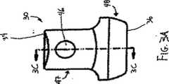
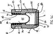
次に、全体として図3a乃至図3dを参照すると、本発明の受入れ部材30の1つの実施の形態が図示されている。受入れ部材30は、上側開口部分31a及び下側開口部分31bを画成し、図示した実施の形態において、これらの開口部分が上端34の上側開孔33から下端36の下側開孔35まで受入れ部材30を通って伸びる単一の開口部32を形成する。1つの特定の実施の形態において、開口部32の下側開口部分31bは、チャンバ壁39により画成されたチャンバ38を備えている。これと代替的に、上側及び下側開口部分31a、31bは、各々が直径の異なる1つ以上の部分を有するような、多岐に亙る形態とすることが可能である。
【0017】
開口部32は、部分的に、受入れ部材30の上端34にて面取り加工又は丸味を付けた端縁40aにより取り巻かれ、また、受入れ部材30の下端36にて面取り加工し又は丸味を付けた端縁40bにより取り巻かれている。下端36に近接して、受入れ部材30は、開口部32の周りに溝41及び関係した棚状突起41aを画成する。図示した実施の形態において、溝41は、開口部32の周縁の周りを一部分のみ伸びるようにすることが可能であるが、該溝41は、開口部32の全周に亙って伸びている。溝41は、溝深さA(図7)及び溝直径B(図3C)を有する。
【0018】
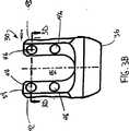
図示した実施の形態における受入れ部材30は、一対の直立分岐部分42、43を備えており、開口部32は、該一対の直立分岐部分42、43を貫通して伸びている。分岐部分42、43は、開口部32を横断するU字形通路45を更に画成し、該U字形通路は開口部32の上側部分31a及び下側部分31bと連通し、また、細長い部材Rを受け入れる(図7)。1つの特定の実施の形態において、分岐部分42、43には内ねじ44が形成されており、分岐部分42、43には、凹陥部又は穴46が形成され、これら穴は、外科医が適当な工具(図示せず)にて受入れ部材30を把持することを許容する。1つの特定の実施の形態における内ねじ44は、逆角度ねじである、すなわち、その開示内容の全体を参考として引用し本明細書に含めた、1998年11月9日出願の本発明と同一人が所有する米国特許出願第09/188,825号に開示されたように、前面が下方を向き且つ受入れ部材30の方を向くねじである。好ましくは、受入れ部材30(分岐部分42、43を含む)の頂部分47は受入れ部材30の底部48よりも狭小であり、これにより、受入れ部材30の大きさ及びプロフィールを縮小させるものであるようにする。
【0019】
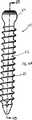
次に、全体として、図4a乃至図4cを参照すると、本発明にて使用される骨アンカー50の1つの実施の形態が図示されている。図示した骨アンカー50は、1つの実施の形態において、その開示内容を参考として引用し本明細書に含めた、米国特許第5,885,286号に開示された骨ねじと実質的に同様の骨ねじである。骨アンカー50は、定着部分52と、頭部分54とを有している。定着部分52は、海綿質セルフタッピングねじとすることのできる少なくとも1つのねじ56を備えている。代替的な曲率及びその他の形態が採用可能であるが、頭部分54は、図示した実施の形態にて1つの球の一部を形成するようにする。1つの特定の実施の形態における頭部54は、クラウン部材70の内側に対する係止力を向上させる一連のリッジ58を備えている(以下に説明)。頭部54は、粗面か又はギザギザ付き面のような代替的な摩擦増進面の形態を備えることができる。更に、頭部54は、工具係合プリント60を有し、該プリント60に対し工具(図示せず)が係合して、定着部分52を骨内に推進することができる。工具係合プリント60は、外側プリントも使用可能であるが、図示した実施の形態にて内側プリントであり、また、六角形、六角裂片形、又はその他の既知のトルク伝導形態のような多数の形態の任意のものとすることができる。
【0020】
骨アンカー50のその他の実施の形態も本発明の範囲に属すると考えられる。例えば、骨アンカー50は、ねじではなくて骨係合フックとしてもよい。この実施の形態において、定着部分52は、ねじ56を有する細長い部分ではなくて、フックを有する形態となる。
【0021】
骨アンカー50の頭部54は、開口部32の下側部分31b及び受入れ部材30のチャンバ38に少なくとも嵌るような形状及び寸法とされている。具体的には、頭部54は、下側開口部分31b及びチャンバ38の幅よりも狭い幅を有する。以下により詳細に説明するように、骨アンカー50は受入れ部材30内に挿入され、頭部54は受入れ部材30の下端部36を通じて下側開口部分31b及びチャンバ38に入る。
【0022】
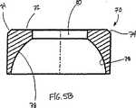
次に、図5a及び図5bを参照すると、本発明のクラウン部材70の1つの実施の形態が図示されている。この実施の形態において、クラウン部材70は、斜角付き端縁74を有する上面72と、下面78とを備える円形ディスクの形状をしている。下面78は、骨アンカー50の頭部54を受け入れる形態とされ、このため、図示した下面78の実施の形態は部分球状の形状をしている。これと代替的に又は追加的にクラウン部材70の下面は、斜角付き又は円錐形下面78´(図5c)のような1つ以上のその他の形状とすることができる。下面78には、骨アンカー50の頭部54と協働する摩擦力又は係止力増進面の形態(例えば、粗面又はギザギザ付き面)を設けることができる。
【0023】
クラウン部材70の図示した実施の形態はまた、穴80を有している。穴80は骨アンカー50の頭部54、特に工具係合プリント60をクラウン部材70を通じてアクセス可能であるように設けられる。クラウン部材70は、開口部32の下側部分31b及び受入れ部材30のチャンバ38に少なくとも嵌り得る寸法及び形状とされている。クラウン部材70の外側寸法は、チャンバ38の内側寸法及び開口部32の下側部分31bよりも僅かに小さく、このため、クラウン部材70はチャンバ38及び開口部32内で摺動可能に且つ回転可能に可動であることが好ましい。更に、図示した実施の形態において、クラウン部材70の外側寸法は上側開口部分31aの内側寸法よりも大きく、このため、クラウン部材70は上側開口部分31a内に動くことはできない。
【0024】
次に、図6a及び図6bを参照すると、本発明の止め部材90の1つの実施の形態が図示されている。図示した実施の形態において、止め部材90は空隙91を画成するC字形ばね又はクリップの形態をしている。止め部材90は上面92及び底面94を有する。図示した実施の形態において、止め部材90は、また、開孔102を実質的に取り巻く内面96、98、100を更に有している。1つの特定の実施の形態において、内面96は、骨アンカー50の頭部54の半径と実質的に等しい半径の球の一部を形成し、内面98は円筒状であり、内面100は円錐形であり且つ外方に角度が付けられて骨アンカー50をより広い角度範囲内で配置することを許容する。代替的な実施の形態において、開孔102を取り巻く単一又は多数の内面が存在し、該面は円筒状、円錐形、球状又はその他の適当な形状とすることができる。開孔102の直径は、骨アンカー50の頭部54の直径及びクラウン部材70の直径よりも小さい。
【0025】
止め部材90は、無荷重状態すなわち自然の外径D、すなわち、止め部材90に何ら収縮応力(空隙を閉じる)又は拡張応力(空隙を開く)が加わらないときに測定された直径を有する。1つの実施の形態において、止め部材90の直径Dは、溝41の溝直径Bよりも大きい。更に、止め部材90は、止め部材90の全体に亙って実質的に一定である本体幅Wを有する。止め部材90の本体幅Wは溝41の溝深さAよりも広い。
【0026】
全体として図1、図2及び図7を参照すると、組立体20は次のようにして組み立てられる。骨アンカー50、クラウン部材70及び止め部材90を個々にすなわち実質的に1つのステップにて下端36を通じて受入れ部材30内に挿入する。例えば、最初にクラウン部材70を挿入し、その後、骨アンカー50を挿入し、最後に止め部材90を挿入する。1つの特定の実施の形態において、止め部材90は、骨アンカー50を受入れ部材30内に挿入する前に、頭部54の真下にて骨アンカー50の周りに装着する。骨アンカー50の定着部分52を止め部材90の開孔102に挿入し、止め部材90を定着部分52の上方に亙って頭部54に向けて動かすことにより、止め部材90を骨アンカー50の周りに配置することができる。これと代替的に、止め部材90の空隙91を頭部54の下方にて骨アンカー50の軸部に対して押し付け、空隙91が拡張して骨アンカー50を止め部材90の開孔102内に配置することを許容し、そのとき、止め部材90がその当初の寸法及び形状に戻るようにしてもよい。クラウン部材70を骨アンカー50の頭部54上に配置し、クラウン部材70の下面78は頭部54に接続し、また、上述したように、骨アンカー50及び止め部材90を共に装着し、骨アンカー50、クラウン部材70及び止め部材90を受入れ部材30内に同時に挿入することができる。
【0027】
クラウン部材70は、開口部32の下側部分31b及び/又は受入れ部材30のチャンバ38内に摺動可能で且つ回転可能に配置されたままであり、骨アンカー50は、クラウン部材70及び受入れ部材30に対して多数の軸方向に可動であるままである。止め部材90は開口部32の下側部分31b内に上方に付勢される。止め部材90の外径が開口部32の下側部分31bの直径と等しくなる迄、止め部材90が受入れ部材30の面取り加工した端縁40bに対し付勢されるとき、止め部材90は収縮して空隙91をより小さくする。止め部材90は開口部32に沿って且つ溝41内に更に前進して、止め部材90が溝41の少なくとも一部分に装着されるようにする。
【0028】
上述したように、1つの特定の実施の形態において、溝41の溝直径Bはその自然(すなわち、無荷重)状態にて止め部材90の外径Dよりも小さい。このため、止め部材90が溝41内にあるとき、止め部材90は溝41の壁に対して押し付けられる。これと代替的に、溝41の溝直径Bは止め部材90の自然の外径Dと等しい寸法又はそれよりも僅かに大きくしてもよい。この場合、止め部材90の下面94は溝41の棚状突起41a上に休止し、これにより、止め部材90を溝41内に保持する。溝41の溝深さAは止め部材90の本体幅Wよりも浅く、このため、止め部材90を溝41内に装着したとき、止め部材90の一部分が開口部32の下側開口部分31b内に突き出す。
【0029】
止めリング90が溝41内に着座したとき、骨アンカー50及びクラウン部材70は受入れ部材30の開口部32内に保持される。クラウン部材70は骨アンカー50の頭部54により支持される一方、頭部54は止め部材90の内面96により支持されている。止め部材90は受入れ部材30の溝41及び/又は棚状突起41aにより保持されており、このため、止めリング90が溝41内にあるとき、骨アンカー50及びクラウン部材70は止めリング90を通り且つ受入れ部材30から出ることはない。
【0030】
好ましくは、外科的方法にて使用する前に、組立体20を組み立てる(上述したように)。組立体20の図示した実施の形態を使用するとき、組立体20の骨アンカー50を適正に処理した骨の穴内にねじ込む(図示せず)。例えば、骨アンカー50が骨フックである、本発明の代替的な実施の形態において、骨に穴を穿孔し且つその内部にアンカーをねじ込むことは不要であることが理解されよう。ねじ付きの定着部分52を骨内に挿入し、クラウン部材70の穴80を通じて骨アンカー50の工具係合プリント60と共に適正なねじ込み工具を使用し、骨内に骨アンカー50をねじ込む。骨アンカー50が所望の深さまで骨内にねじ込まれたならば、開口部32が図1に図示するように、骨アンカー50に対して所望の角度を形成するように、受入れ部材30を配置する。図示した実施の形態において、骨アンカー50と開口部32との間の角度θは、任意の方向に向けて30°以内の任意の値とすることができる。例えば、頭部54の下方の骨アンカー50の厚さを薄くし、面取り加工端縁40bをより急峻な角度とし且つ/又は溝41を受入れ部材30の下端36に可能な限り近接して配置する等の幾つかの方法にて、開口部32に対する骨アンカー50の最大角度を変更することが可能であることが理解されよう。
【0031】
上述したように、受入れ部材30は、骨アンカー50に対して外科医が望む角度とすることができる。脊柱ロッド、コネクタ又はその他の整形学的外科用インプラントのような細長い部材Rを組立体20と接続する。細長い部材Rは受入れ部材30の通路45内に配置され、クラウン部材70の上面72に接触する。止めねじ又はねじ付きプラグのような圧縮部材120を受入れ部材30のねじ44内に且つ細長い部材Rまでねじ込む。1つの実施の形態において、圧縮部材120は、トルクを加える外ねじ122及びプリント124を有する止めねじ又はプラグであり、特定の実施の形態において、その内容を参考として引用し本明細書に含めた、シャーマンらへの米国特許第5,885,286号に開示されたような破断止めねじである。更なる実施の形態において、ねじ122は、上述した受入れ部材30のねじ部44の逆角度の実施の形態と適合可能である、その内容を参考として引用し本明細書に含めた1998年11月9日付け出願の米国特許出願第09/188,825号に開示されたような逆角度ねじである。これと代替的に、受入れ部材30が外ねじ付きである場合、圧縮部材120は内ねじ付きナットとすることができる。
【0032】
圧縮部材120を締め付けると、細長い部材Rはクラウン部材70に対して下方に押し付けられ、このことは、クラウン部材70を骨アンカー50の頭部54に対して押し付けることになる。これにより、頭部54は、止め部材90とクラウン部材70との間にクランプ止めされる。頭部54がリッジ58を含む本発明の実施の形態において、リッジ58はクラウン部材70の下面78内に押し込まれる。このようにして、骨アンカー50は細長い部材R及び組立体20の他の部分に対して所望の角度位置に係止される。
【0033】
これと代替的に、外科手術中に組立体20を組み立ててもよい。止めリング90が既に頭部54の下方に配置された状態で骨アンカー50を骨内に挿入する。クラウン部材70を骨アンカー50の頂部又は受入れ部材30の開口部32内に配置する。次に、受入れ部材30を骨アンカー50の頭部54に押し付け、止め部材90を強制的に収縮させ、開口部32に入り且つ上述したように、溝41内に着座するようにする。このようにして、組立体20を組み立てた後、細長い部材を受入れ部材30内に装填し且つ上述したように係止する。
【0034】
本発明にとって好ましい材料は、ステンレススチール及びチタンを含む。本発明の骨接合及びその他の整形外科的目標を達成するために任意の堅牢な生体適合性材料が使用可能であることが理解されよう。1つの特別な実施の形態において、クラウン部材70は骨アンカー50の頭部54のリッジ58に使用される材料よりも多少柔軟な材料で形成することができる。かかる構造は、組立体20を係止する間、リッジ58がクラウン部材70の内面78内に多少より容易に貫入し、これにより、リッジ58とクラウン部材70との間により確実な係止力を提供することを許容する。別の特定の実施の形態において、クラウン部材70は、細長い部材Rに対して使用される材料よりも多少柔軟な材料で形成することができる。かかる構造体は、組立体20を係止する間、クラウン部材70の上面72が細長い部材Rの形状に変形するのを許容し、また、インプラントをより確実に係止することを可能にする。
【0035】
図面及び上記の説明にて本発明を記述し且つ詳細に説明したが、これは単に一例であり、性質を限定するものではないとみなすべきである。好ましい実施の形態のみを図示し且つ記載したものであり、本発明の精神の範囲に属する全ての変更及び改変例を保護対象に含めることを望むものであることを理解すべきである。
【図面の簡単な説明】
【図1】 本発明のマルチアキシャル骨ねじアンカー組立体の1つの実施の形態の側面図である。
【図2】 図1に図示した本発明の実施の形態の分解図である。
【図3】 3aは、図2に図示した本発明の実施の形態における受入れ部材の1つの実施の形態を示す側面図である。
3bは、図3aに図示した受入れ部材の実施の形態における正面図である。
3cは、図3aに図示した受入れ部材の実施の形態における図3aの線3c−3cに沿い且つ矢印の方向に見た断面図である。
3dは、図3aに図示した受入れ部材の実施の形態における図3bの線3d−3dに沿い且つ矢印の方向に見た断面図である。
【図4】 4aは、図2に図示した本発明の実施の形態にて使用される骨アンカーの1つの実施の形態を示す側面図である。
4bは、図4aに図示した骨アンカーの実施の形態における図4aの線4b−4bに沿い且つ矢印の方向に見た断面図である。
4cは、図4aに図示した骨アンカーの頭部の1つの実施の形態における拡大図である。
【図5】 5aは、図2に図示した本発明の実施の形態にて使用されるクラウン部材の1つの実施の形態を示す平面図である。
5bは、図5aに図示したクラウン部材の実施の形態における図5aの線5b−5bに沿い且つ矢印の方向に見た断面図である。
5cは、図2に図示した本発明の実施の形態にて使用されるクラウン部材の別の実施の形態を示す図5bと実質的に同様の断面図である。
【図6】 6aは、図2に図示した本発明の実施の形態にて使用される止め部材の1つの実施の形態を示す平面図である。
6bは、図6aに図示した止め部材の実施の形態における図6aの線6b−6bに沿い且つ矢印の方向に見た断面図である。
【図7】 図1に図示した本発明の実施の形態を示す拡大断面図である。[0001]
FIELD OF THE INVENTION
The present invention relates to devices and implants used in osteosynthesis and other orthopedic methods. In particular, the present invention is directed to a bottom-loading bone anchor assembly that can provide multiple angular orientations for an elongated member extending along bone tissue.
[0002]
[Technology of the Invention]
Several techniques and devices have been developed to correct and stabilize bone, especially long bone and spinal column injuries or malfunctions. In one type of device, an elongated member such as a bendable rod is disposed longitudinally along the length of the bone. In spinal applications, the rod is preferably bent to correspond to the normal curvature of the spine in the particular area where the brace is attached. For example, the rod can be bent to form a normal back curvature for the thoracic vertebral region of the spine or an anterior curvature for the lumbar region. According to such a device, the rod can engage various vertebrae along the length of the spinal column via a number of fixation elements. A wide variety of fixation elements configured to engage vertebrae and other portions of bone can be provided. For example, one such fixation element is a hook configured to engage a vertebral stack. Another very common fixation element is a screw that can be screwed into various parts of the vertebra or other bone.
[0003]
In one typical spinal method utilizing a bendable rod, the rod is placed on either side of the spinal column or spinous process. Within a portion of several vertebral bodies, very often, multiple bone screws are screwed into the pedicles of these vertebrae. The rod is fixed to the plurality of bone screws so as to impart corrective and stabilizing forces to the spinal column.
[0004]
An example of a rod-type spinal fixation device is the TSRH® spinal device sold by Medtronic Sofamor Danek Incorporated. This TSRH device comprises an elongated rod and a wide variety of hooks, screws and bolts, all of which can form a segmented structure over the entire spinal column. It is said that. In one aspect of the TSRH® device, the spinal column-rod is connected to various vertebral fixation elements via eyebolts. In this configuration, the fixation element engages the spinal rod adjacent to the lateral direction of the rod. In another aspect of the TSRH device, a variable angle screw is engaged to the spinal rod via an eyebolt. This variable angle screw allows the bone screw to pivot in a single plane parallel to the plane of the spinal rod. Details of this variable angle screw can be found in US Pat. No. 5,261,909 to Sterlin et al., Owned by the assignee of the present invention. One purpose realized by the TSRH® device is that the surgeon can attach a vertebral fixation element, such as a spinal hook or bone screw, to the spinal column at the proper body part location. The TSRH® device also allows the surgeon to easily engage each of the fixation elements to ultimately tighten the bent spinal rod.
[0005]
Another rod-type fastening device is the Cotrel-Duboset / CD (R) Spinal system sold by Medtronic Sofamall Duneck Inc. Similar to the TSRH® device, the CD® device provides a variety of fixation elements that engage the elongate rod and the spinal column. In one aspect of the CD device, the fixation element itself comprises a body defining a slot in which a spinal rod is received. The slot has a threaded hole with which a threaded plug engages so that the rod can be clamped into the body of the securing element. The CD device has a hook and bone screw in this “rear open” configuration. Details of this technique can be found in US Pat. No. 5,005,562 to Cotrel. One advantage of this feature of the CD device is that the securing element is located directly under the elongated rod. This helps to reduce the overall size of the implant structure and minimizes wounds to the surrounding tissue.
[0006]
On the other hand, these fixation elements of the CD device can only be pivoted around the spinal rod so that a variable angle position relative to the rod can be achieved. While this limited range of relative angular positions is acceptable for many spinal abnormalities, many other cases require, for example, more original orientation of the bone screw relative to the spinal rod. Some aspects of this problem are addressed by the variable angle screw of the TSRH® device, as described in US Pat. No. 5,261,909. However, there is a need for a bone screw that can be angularly set in multiple planes relative to the spinal rod. Preferably, the bone screw allows various three-dimensional orientations relative to the spinal rod. This type of screw is referred to as a polyaxial or multiaxial bone screw.
[0007]
Some polyaxial screw designs attempt to address this issue. For example, US Pat. No. 5,466,237 to Byrd et al. Describes a bone screw having a spherical projection on the top of the bone screw. An externally threaded receiving member supports the bone screw and spinal rod at the top of the spherical projection. The outer nut is tightened on the receiving member to press the spinal rod against the spherical projection to accommodate the various angular orientations of the bone screw relative to the rod. This particular solution uses minimal components but lacks certainty of securing the bone screw to the rod. In other words, the engagement or fixation between the small spherical process of the bone screw and the spinal rod is easily separated when a large spinal load is applied to the brace, particularly in the lumbar region.
[0008]
In another solution described in US Pat. No. 4,946,458 to Harms et al., A spherical head bone screw is supported in a separate half of the receiving member. The bottoms of these halves are held together by a retaining ring. The top of the receiving member half is compressed around the bone screw by a nut screwed onto a threaded spinal rod. In another solution by Hams et al., US Pat. No. 5,207,678, a receiving member is flexibly connected around a partial spherical head of a bone screw. The conical nuts on both sides of the receiving member are screwed to a threaded rod that passes through the receiving member. As the conical nuts are screwed towards each other, the receiving member compresses flexibly around the bone screw head to clamp the bone screw in its variable angular position. One drawback of the device in the two Harms et al. Patents is that the spinal rod must be threaded to accept the compression nut. It is known that threaded rods tend to weaken when subjected to significant spinal loads. In addition, the bone screw designs described in US Pat. No. 4,946,458 and US Pat. No. 5,207,678 require a large number of parts and are quite substantial in order to fully secure the bone screw. It is complicated.
[0009]
A further solution described in US Pat. No. 5,797,911 to Sheman et al., Owned by the assignee of the present invention, provides a U-shaped holder and has a crown member at the top. A load is applied to the fastener through the top of this U-shaped holder. The holder receives a rod in the passage above the crown member and a compression member above the rod. The compression member is pressed against the rod and the crown member to lock the fastener to the holder at an arbitrary three-dimensional angle with respect to the rod. This solution has been found to be extremely effective in addressing the above-mentioned problems. However, this method does not allow bottom loading of fasteners. In addition, the holder is somewhat larger to accept other structural components.
[0010]
A further solution is described in US Pat. No. 5,733,285 to Errico et al., In which the holder is provided with a tapered and colleted part at its bottom. The head of the bone fastener is inserted into this part. A sleeve is provided that slides down around the colleted portion so that the colleted portion can collapse and lock around the head of the bone fastener. This device is considered to be relatively large and difficult to operate due to the presence of an outer sliding locking mechanism. This device further relies on the outer sleeve fitting and the collet, its bending and the relative strength of the collapsed portion to securely lock the bone fastener head.
[0011]
This includes the profile and size of the components used to engage the bone anchor with the elongated member at any angle in the improved angle, improved strength and a wide variety of angular orientations of the bone anchor. It can be easily and reliably engaged with an elongated member that achieves reduced dimensions, i.e. smooth, rough, knurled and even threaded. There remains a need in the art for multi-axial bone anchors.
[0012]
Summary of the Invention
In one embodiment of the present invention, a receiving member comprising an upper opening portion and a lower opening portion, a passage in communication with the upper and lower opening portions and configured to receive an elongate member; A bone fixation assembly is provided having the receiving member defining a groove around a portion of the side opening. The assembly has an upper surface and a lower surface, a crown member movably disposed within the lower opening portion, a lower portion configured to engage the bone, and a head smaller than the lower opening portion. And a bone engaging anchor having a portion, the head being movably disposed within the lower opening portion adjacent to the concave lower surface of the crown member. The assembly also includes a stop member that defines an aperture that is smaller than the head of the bone anchor, the stop member being at least partially received within the groove of the receiving member and around the bone anchor. And below the head.
[0013]
Further embodiments, examples, advantages and objects of the invention will become apparent to those skilled in the art from the following description of this specification.
[0014]
[Description of Preferred Embodiment]
For the purpose of promoting an understanding of the principles of the invention, reference will now be made to the embodiment illustrated in the drawings and specific language will be used to describe the same. However, this is not intended to limit the scope of the present invention in any way, but is intended to alter the apparatus and further modifications described herein as well as further applications of the principles of the present invention described herein. It should be understood that the examples are typically devised by those skilled in the art to which this invention pertains.
[0015]
Referring generally to FIGS. 1 and 2, one embodiment of the multi-axial
[0016]
Referring now generally to FIGS. 3a-3d, one embodiment of the receiving
[0017]
The opening 32 is partially surrounded by an edge 40a that is chamfered or rounded at the
[0018]
The receiving
[0019]
Referring now generally to FIGS. 4a-4c, one embodiment of a
[0020]
Other embodiments of the
[0021]
The
[0022]
5a and 5b, one embodiment of the
[0023]
The illustrated embodiment of the
[0024]
6a and 6b, one embodiment of the
[0025]
The
[0026]
Referring to FIGS. 1, 2 and 7 as a whole, the
[0027]
The
[0028]
As described above, in one specific embodiment, the groove diameter B of the groove 41 is smaller than the outer diameter D of the
[0029]
When the retaining
[0030]
Preferably, the
[0031]
As described above, the receiving
[0032]
When the
[0033]
Alternatively,
[0034]
Preferred materials for the present invention include stainless steel and titanium. It will be appreciated that any robust biocompatible material can be used to achieve the osteosynthesis and other orthopedic goals of the present invention. In one particular embodiment, the
[0035]
While the invention has been described and described in detail in the drawings and foregoing description, the same is to be considered as illustrative and not restrictive in character. It should be understood that only the preferred embodiments have been illustrated and described, and that all changes and modifications that fall within the spirit of the invention are desired to be covered.
[Brief description of the drawings]
FIG. 1 is a side view of one embodiment of a multi-axial bone screw anchor assembly of the present invention.
FIG. 2 is an exploded view of the embodiment of the present invention illustrated in FIG.
3a is a side view showing one embodiment of the receiving member in the embodiment of the present invention shown in FIG. 2. FIG.
3b is a front view of the embodiment of the receiving member shown in FIG. 3a.
3c is a cross-sectional view taken along line 3c-3c of FIG. 3a and in the direction of the arrow in the embodiment of the receiving member shown in FIG. 3a.
3d is a cross-sectional view taken along line 3d-3d in FIG. 3b and in the direction of the arrow in the embodiment of the receiving member shown in FIG. 3a.
4a is a side view illustrating one embodiment of a bone anchor used in the embodiment of the invention illustrated in FIG.
4b is a cross-sectional view of the embodiment of the bone anchor shown in FIG. 4a, taken along line 4b-4b in FIG. 4a and viewed in the direction of the arrow.
4c is an enlarged view of one embodiment of the head of the bone anchor illustrated in FIG. 4a.
FIG. 5a is a plan view showing one embodiment of a crown member used in the embodiment of the present invention shown in FIG.
5b is a cross-sectional view taken along line 5b-5b of FIG. 5a and in the direction of the arrow in the embodiment of the crown member shown in FIG. 5a.
5c is a cross-sectional view substantially similar to FIG. 5b showing another embodiment of the crown member used in the embodiment of the present invention shown in FIG.
6a is a plan view showing one embodiment of a stop member used in the embodiment of the present invention shown in FIG. 2. FIG.
6b is a cross-sectional view taken along line 6b-6b of FIG. 6a and in the direction of the arrow in the embodiment of the stop member shown in FIG. 6a.
7 is an enlarged sectional view showing the embodiment of the present invention shown in FIG. 1. FIG.
Claims (29)
Translated fromJapanese受入れ部材であって、各々がそれぞれの最小幅を有する上側開口部分及び下側開口部分と、細長い部材を受け入れる形態とされ且つ前記上側開口部分及び前記下側開口部分と連通する通路と、前記下側開口部分の一部分の周りの溝とを画成する前記受入れ部材と、
前記下側開口部分内に可動に配置されたクラウン部材であって、上面及び下面を有する前記クラウン部材と、
骨と係合する形態とされた下側部分とある幅の頭部とを有する骨係合アンカーであって、該頭部の該幅が前記下側開口部分の前記最小幅よりも狭く、前記頭部が、前記クラウン部材の前記下面に隣接して前記下側開口部分内に可動に配置された前記骨係合アンカーと、
前記頭部の前記幅よりも狭い開孔を画成する止め部材であって、前記受入れ部材の前記溝内に少なくとも部分的に収容されて、前記アンカーの周りで且つ前記頭部の下方に配置された前記止め部材と
を備え、
前記止め部材は、C字形部材であり、上面、底面、前記止め部材の前記開孔を取り巻く第1、第2および第3の内面を備え、第1の内面は前記上面に隣接し前記骨係合アンカーの前記頭部の半径と等しい半径の球の一部を形成し、第2の内面は円筒状であり且つ第1及び第3の内面の間に設けられ、第3の内面は円錐形であり、前記底面に隣接し且つ外方に角度がつけられており、
該止め部材が、前記頭部が前記下側開口部分から除去されるのを防止する、骨アンカー組立体。In a bone anchor assembly engaging an elongated member,
A receiving member, each having an upper opening portion and a lower opening portion each having a respective minimum width; a passage configured to receive an elongated member and communicating with the upper opening portion and the lower opening portion; The receiving member defining a groove around a portion of the side opening portion;
A crown member movably disposed in the lower opening portion, the crown member having an upper surface and a lower surface;
A bone engaging anchor having a lower portion configured to engage bone and a width head, wherein the width of the head is less than the minimum width of the lower opening portion; The bone engaging anchor having a head movably disposed in the lower opening portion adjacent to the lower surface of the crown member;
A stop member defining an aperture narrower than the width of the head, wherein the stop member is at least partially housed in the groove of the receiving member and is disposed about the anchor and below the head Said stop member,
The stop member is a C-shaped member, and includes anupper surface, a bottom surface, and first, second, and third inner surfaces surrounding the opening of the stop member, and the first innersurface is adjacent to the upper surface and is associated with the bone anchor. Forming a part of a sphere having a radius equal to the radius of the head of the mating anchor, the second inner surface being cylindricaland provided between the first and third inner surfaces , the third inner surface being conical Isadjacent to the bottom surface and angled outward.
A bone anchor assembly, wherein the stop member prevents the head from being removed from the lower opening portion.
少なくとも1つの骨に隣接し且つ該骨の長さに沿って配置し得る形態とされた細長い部材と、
受入れ部材であって、上端から下端まで貫通する開口部を有し、該開口部が前記下端に下側開孔を有し且つ前記上端に上側開孔を有し、前記開口部の一部分の周りに溝を画成し、該溝が前記下側開孔に近接し、前記開口部及び前記上側開孔と連通する通路を更に有し、該通路が前記細長い部材を内部に受け入れ得る形態とされた前記受入れ部材と、
前記下側開孔を通じて挿入可能であり且つ前記開口部内に配置されたクラウン部材であって、下面と、前記細長い部材に接触する反対側の上面とを有する前記クラウン部材と、
骨に係合し得る形態とされた下側部分と、ある幅寸法の頭部とを有する骨アンカーであって、前記頭部が前記下側開孔を通じて挿入可能であり且つ前記受入れ部材の前記開口部内で前記クラウン部材に隣接する前記骨アンカーと、
前記頭部の前記幅寸法よりも小さい幅寸法を有する開孔を画成する止め部材であって、前記骨アンカーの一部分の周りで且つ前記頭部の下方に配置され、該止め部材の少なくとも一部分が前記溝の少なくとも一部分内に配置されており、前記止め部材は、C字形部材であり、上面、底面、前記止め部材の前記開孔を取り巻く第1、第2および第3の内面を備え、第1の内面は前記上面に隣接し前記骨アンカーの前記頭部の半径と等しい半径の球の一部を形成し、第2の内面は円筒状であり且つ第1および第3の内面の間に設けられ、第3の内面は円錐形であり、前記底面に隣接し且つ外方に角度がつけられている、前記止め部材と、
前記上側開孔に近接して前記開口部内に係合した圧縮部材であって、前記細長い部材を前記クラウン部材に対して押し付け、これにより、前記骨アンカーの前記頭部を前記クラウン部材と前記止め部材との間に固定する前記圧縮部材と
を備える、装置。In the bone anchoring device,
An elongate member configured to be positioned adjacent to and along the length of the at least one bone;
A receiving member having an opening penetrating from the upper end to the lower end, the opening having a lower opening at the lower end and an upper opening at the upper end, around a portion of the opening And further comprising a passage adjacent to the lower opening and communicating with the opening and the upper opening, the passage being configured to receive the elongated member therein. The receiving member;
A crown member insertable through the lower aperture and disposed within the opening, the crown member having a lower surface and an upper surface on the opposite side contacting the elongated member;
A bone anchor having a lower portion configured to engage a bone and a head having a width dimension, the head being insertable through the lower aperture and the receiving member The bone anchor adjacent to the crown member in an opening;
A stop member defining an aperture having a width dimension that is smaller than the width dimension of the head portion, the stop member being disposed around a portion of the bone anchor and below the head portion, wherein at least a portion of the stop member. Is disposed in at least a portion of the groove, and the stop member is a C-shaped member, and includes atop surface, a bottom surface, and first, second and third inner surfaces surrounding the opening of the stop member, The first innersurface is adjacent to the upper surface and forms a portion of a sphere having a radius equal to the radius of the head of the bone anchor, the second inner surface is cylindricaland between the first and third inner surfaces And the third inner surface is conical, isadjacent to the bottom surface and is angled outwardly; and
A compression member engaged in the opening adjacent to the upper aperture, wherein the elongate member is pressed against the crown member, whereby the head of the bone anchor is clamped with the crown member The said compression member fixed between members.
Applications Claiming Priority (3)
| Application Number | Priority Date | Filing Date | Title |
|---|---|---|---|
| US09/387,991US6280442B1 (en) | 1999-09-01 | 1999-09-01 | Multi-axial bone screw assembly |
| US09/387,991 | 1999-09-01 | ||
| PCT/US2000/040771WO2001015612A1 (en) | 1999-09-01 | 2000-08-29 | Multi-axial bone screw assembly |
Publications (3)
| Publication Number | Publication Date |
|---|---|
| JP2003508109A JP2003508109A (en) | 2003-03-04 |
| JP2003508109A5 JP2003508109A5 (en) | 2007-05-17 |
| JP4318421B2true JP4318421B2 (en) | 2009-08-26 |
Family
ID=23532168
Family Applications (1)
| Application Number | Title | Priority Date | Filing Date |
|---|---|---|---|
| JP2001519829AExpired - LifetimeJP4318421B2 (en) | 1999-09-01 | 2000-08-29 | Multiaxial bone screw assembly |
Country Status (10)
| Country | Link |
|---|---|
| US (5) | US6280442B1 (en) |
| EP (1) | EP1214006B1 (en) |
| JP (1) | JP4318421B2 (en) |
| CN (1) | CN1192749C (en) |
| AT (1) | ATE306854T1 (en) |
| AU (1) | AU773530B2 (en) |
| CA (1) | CA2382033C (en) |
| DE (1) | DE60023323T2 (en) |
| ES (1) | ES2250201T3 (en) |
| WO (1) | WO2001015612A1 (en) |
Families Citing this family (569)
| Publication number | Priority date | Publication date | Assignee | Title |
|---|---|---|---|---|
| ATE151583T1 (en)* | 1990-02-05 | 1997-04-15 | Scitex Corp Ltd | DEVICES AND METHODS FOR PROCESSING DATA, SUCH AS COLOR IMAGES |
| US5782833A (en)* | 1996-12-20 | 1998-07-21 | Haider; Thomas T. | Pedicle screw system for osteosynthesis |
| FR2796545B1 (en)* | 1999-07-22 | 2002-03-15 | Dimso Sa | POLY-AXIAL LINK FOR OSTEOSYNTHESIS SYSTEM, ESPECIALLY FOR THE RACHIS |
| US6280442B1 (en)* | 1999-09-01 | 2001-08-28 | Sdgi Holdings, Inc. | Multi-axial bone screw assembly |
| DE10005385A1 (en)* | 2000-02-07 | 2001-08-09 | Ulrich Gmbh & Co Kg | Pedicle screw |
| US6235033B1 (en)* | 2000-04-19 | 2001-05-22 | Synthes (Usa) | Bone fixation assembly |
| US7985247B2 (en)* | 2000-08-01 | 2011-07-26 | Zimmer Spine, Inc. | Methods and apparatuses for treating the spine through an access device |
| US7056321B2 (en) | 2000-08-01 | 2006-06-06 | Endius, Incorporated | Method of securing vertebrae |
| US7833250B2 (en)* | 2004-11-10 | 2010-11-16 | Jackson Roger P | Polyaxial bone screw with helically wound capture connection |
| US7837716B2 (en)* | 2000-08-23 | 2010-11-23 | Jackson Roger P | Threadform for medical implant closure |
| US20060025771A1 (en)* | 2000-08-23 | 2006-02-02 | Jackson Roger P | Helical reverse angle guide and advancement structure with break-off extensions |
| US6485491B1 (en)* | 2000-09-15 | 2002-11-26 | Sdgi Holdings, Inc. | Posterior fixation system |
| US8512380B2 (en)* | 2002-08-28 | 2013-08-20 | Warsaw Orthopedic, Inc. | Posterior fixation system |
| ES2240384T3 (en)* | 2000-09-18 | 2005-10-16 | Zimmer Gmbh | PEDICULAR SCREW FOR INTERVERTEBRAL SUPPORT ELEMENT. |
| DE10055888C1 (en)* | 2000-11-10 | 2002-04-25 | Biedermann Motech Gmbh | Bone screw, has connector rod receiving part with unsymmetrically arranged end bores |
| US6368321B1 (en)* | 2000-12-04 | 2002-04-09 | Roger P. Jackson | Lockable swivel head bone screw |
| US6726689B2 (en) | 2002-09-06 | 2004-04-27 | Roger P. Jackson | Helical interlocking mating guide and advancement structure |
| US8377100B2 (en) | 2000-12-08 | 2013-02-19 | Roger P. Jackson | Closure for open-headed medical implant |
| US6488681B2 (en)* | 2001-01-05 | 2002-12-03 | Stryker Spine S.A. | Pedicle screw assembly |
| US6969610B2 (en)* | 2001-01-12 | 2005-11-29 | University Of Rochester | Methods of modifying cell structure and remodeling tissue |
| FR2822053B1 (en)* | 2001-03-15 | 2003-06-20 | Stryker Spine Sa | ANCHORING MEMBER WITH SAFETY RING FOR SPINAL OSTEOSYNTHESIS SYSTEM |
| US8292926B2 (en) | 2005-09-30 | 2012-10-23 | Jackson Roger P | Dynamic stabilization connecting member with elastic core and outer sleeve |
| US10729469B2 (en) | 2006-01-09 | 2020-08-04 | Roger P. Jackson | Flexible spinal stabilization assembly with spacer having off-axis core member |
| US10258382B2 (en) | 2007-01-18 | 2019-04-16 | Roger P. Jackson | Rod-cord dynamic connection assemblies with slidable bone anchor attachment members along the cord |
| US7862587B2 (en) | 2004-02-27 | 2011-01-04 | Jackson Roger P | Dynamic stabilization assemblies, tool set and method |
| US20160242816A9 (en) | 2001-05-09 | 2016-08-25 | Roger P. Jackson | Dynamic spinal stabilization assembly with elastic bumpers and locking limited travel closure mechanisms |
| US8353932B2 (en) | 2005-09-30 | 2013-01-15 | Jackson Roger P | Polyaxial bone anchor assembly with one-piece closure, pressure insert and plastic elongate member |
| US6770075B2 (en) | 2001-05-17 | 2004-08-03 | Robert S. Howland | Spinal fixation apparatus with enhanced axial support and methods for use |
| US7314467B2 (en) | 2002-04-24 | 2008-01-01 | Medical Device Advisory Development Group, Llc. | Multi selective axis spinal fixation system |
| CH695478A5 (en)* | 2001-07-20 | 2006-06-15 | Werner Hermann | Threaded bolt, and Pedrikelschraube Pedrikelschraube with threaded bolt |
| ATE498366T1 (en)* | 2001-08-13 | 2011-03-15 | Laurence M Mckinley | VERTEBRATE ALIGNMENT AND FIXATION ARRANGEMENT |
| US6520963B1 (en) | 2001-08-13 | 2003-02-18 | Mckinley Lawrence M. | Vertebral alignment and fixation assembly |
| US6974460B2 (en)* | 2001-09-14 | 2005-12-13 | Stryker Spine | Biased angulation bone fixation assembly |
| KR100379194B1 (en)* | 2001-10-31 | 2003-04-08 | U & I Co Ltd | Apparatus for fixing bone |
| WO2003041601A1 (en)* | 2001-11-14 | 2003-05-22 | Synthes Ag Chur | Device for joining a longitudinal support with a bone fixation means |
| FR2832308B1 (en)* | 2001-11-22 | 2004-09-24 | Guillaume Derouet | ORTHOPEDIC IMPLANT CONSTITUTES A SUPPORT STRUCTURE EQUIPPED WITH AT LEAST ONE ORIFICE FOR THE PASSING OF A FIXATION SCREW ASSOCIATED WITH A NUT |
| DE10157969C1 (en)* | 2001-11-27 | 2003-02-06 | Biedermann Motech Gmbh | Element used in spinal and accident surgery comprises a shaft joined to a holding element having a U-shaped recess with two free arms having an internal thread with flanks lying at right angles to the central axis of the holding element |
| CA2471843C (en)* | 2001-12-24 | 2011-04-12 | Synthes (U.S.A.) | Device for osteosynthesis |
| CN1432343A (en)* | 2002-01-17 | 2003-07-30 | 英属维京群岛商冠亚生技控股集团股份有限公司 | Rotary controlled vertebra fixture |
| US7066937B2 (en) | 2002-02-13 | 2006-06-27 | Endius Incorporated | Apparatus for connecting a longitudinal member to a bone portion |
| US7879075B2 (en) | 2002-02-13 | 2011-02-01 | Zimmer Spine, Inc. | Methods for connecting a longitudinal member to a bone portion |
| US6837889B2 (en) | 2002-03-01 | 2005-01-04 | Endius Incorporated | Apparatus for connecting a longitudinal member to a bone portion |
| WO2003086204A2 (en)* | 2002-04-09 | 2003-10-23 | Neville Alleyne | Bone fixation apparatus |
| US7842073B2 (en)* | 2002-04-18 | 2010-11-30 | Aesculap Ii, Inc. | Screw and rod fixation assembly and device |
| US6740086B2 (en) | 2002-04-18 | 2004-05-25 | Spinal Innovations, Llc | Screw and rod fixation assembly and device |
| ATE384699T1 (en)* | 2002-04-30 | 2008-02-15 | Ucb Pharma Sa | 2,6-QUINOLINYL AND 2,6-NAPHTHHYL DERIVATIVES AND USES THEREOF FOR TREATING VLA-4 RELATED DISEASES |
| US11224464B2 (en) | 2002-05-09 | 2022-01-18 | Roger P. Jackson | Threaded closure with inwardly-facing tool engaging concave radiused structures and axial through-aperture |
| US8257402B2 (en) | 2002-09-06 | 2012-09-04 | Jackson Roger P | Closure for rod receiving orthopedic implant having left handed thread removal |
| WO2006052796A2 (en) | 2004-11-10 | 2006-05-18 | Jackson Roger P | Helical guide and advancement flange with break-off extensions |
| US8876868B2 (en) | 2002-09-06 | 2014-11-04 | Roger P. Jackson | Helical guide and advancement flange with radially loaded lip |
| US20060009773A1 (en)* | 2002-09-06 | 2006-01-12 | Jackson Roger P | Helical interlocking mating guide and advancement structure |
| US8282673B2 (en) | 2002-09-06 | 2012-10-09 | Jackson Roger P | Anti-splay medical implant closure with multi-surface removal aperture |
| DE10246177A1 (en)* | 2002-10-02 | 2004-04-22 | Biedermann Motech Gmbh | Anchor element consists of screw with head, bone-thread section on shank and holder joining rod-shaped part to screw. with cavities in wall, and thread-free end of shank |
| AU2003287273C1 (en) | 2002-10-30 | 2010-01-07 | Zimmer Spine, Inc. | Spinal stabilization system insertion and methods |
| US9539012B2 (en) | 2002-10-30 | 2017-01-10 | Zimmer Spine, Inc. | Spinal stabilization systems with quick-connect sleeve assemblies for use in surgical procedures |
| US8162989B2 (en)* | 2002-11-04 | 2012-04-24 | Altus Partners, Llc | Orthopedic rod system |
| KR100495876B1 (en)* | 2002-11-25 | 2005-06-16 | 유앤아이 주식회사 | bone fixation appratus and assembling method and tool |
| US20040111088A1 (en)* | 2002-12-06 | 2004-06-10 | Picetti George D. | Multi-rod bone attachment member |
| US7887539B2 (en) | 2003-01-24 | 2011-02-15 | Depuy Spine, Inc. | Spinal rod approximators |
| WO2004069066A1 (en)* | 2003-02-03 | 2004-08-19 | Stryker Trauma Sa | Implantable orthopaedic device |
| WO2007035884A2 (en)* | 2005-09-20 | 2007-03-29 | Pioneer Surgical Technology, Inc. | Spinal fixation systems |
| US7141051B2 (en) | 2003-02-05 | 2006-11-28 | Pioneer Laboratories, Inc. | Low profile spinal fixation system |
| US20040162558A1 (en) | 2003-02-18 | 2004-08-19 | Hegde Sajan K. | Spinal plate having an integral rod connector portion |
| DE10310540B3 (en)* | 2003-03-11 | 2004-08-19 | Biedermann Motech Gmbh | Anchoring element for bone or spinal column surgery has threaded shaft and cylindrical reception part for coupling with rod having U-shaped seating with screw threads at ends of its arms |
| US20040186473A1 (en)* | 2003-03-21 | 2004-09-23 | Cournoyer John R. | Spinal fixation devices of improved strength and rigidity |
| US6716214B1 (en) | 2003-06-18 | 2004-04-06 | Roger P. Jackson | Polyaxial bone screw with spline capture connection |
| US8540753B2 (en)* | 2003-04-09 | 2013-09-24 | Roger P. Jackson | Polyaxial bone screw with uploaded threaded shank and method of assembly and use |
| US6964666B2 (en)* | 2003-04-09 | 2005-11-15 | Jackson Roger P | Polyaxial bone screw locking mechanism |
| US7621918B2 (en) | 2004-11-23 | 2009-11-24 | Jackson Roger P | Spinal fixation tool set and method |
| US20040210216A1 (en)* | 2003-04-17 | 2004-10-21 | Farris Robert A | Spinal fixation system and method |
| DE10320417A1 (en) | 2003-05-07 | 2004-12-02 | Biedermann Motech Gmbh | Dynamic anchoring device and dynamic stabilization device for bones, in particular for vertebrae, with such an anchoring device |
| DE20307776U1 (en)* | 2003-05-19 | 2004-09-23 | Metz-Stavenhagen, Peter, Dr.med. | Anchoring element for fastening a rod of a device for setting up a human or animal spine to a vertebral bone |
| US7377923B2 (en) | 2003-05-22 | 2008-05-27 | Alphatec Spine, Inc. | Variable angle spinal screw assembly |
| JP4357486B2 (en)* | 2003-06-18 | 2009-11-04 | ロジャー・ピー・ジャクソン | Polyaxial bone screw with spline capture connection |
| US7766915B2 (en) | 2004-02-27 | 2010-08-03 | Jackson Roger P | Dynamic fixation assemblies with inner core and outer coil-like member |
| US8092500B2 (en) | 2007-05-01 | 2012-01-10 | Jackson Roger P | Dynamic stabilization connecting member with floating core, compression spacer and over-mold |
| US8366753B2 (en) | 2003-06-18 | 2013-02-05 | Jackson Roger P | Polyaxial bone screw assembly with fixed retaining structure |
| US7776067B2 (en) | 2005-05-27 | 2010-08-17 | Jackson Roger P | Polyaxial bone screw with shank articulation pressure insert and method |
| US8926670B2 (en) | 2003-06-18 | 2015-01-06 | Roger P. Jackson | Polyaxial bone screw assembly |
| US8257398B2 (en)* | 2003-06-18 | 2012-09-04 | Jackson Roger P | Polyaxial bone screw with cam capture |
| US8398682B2 (en) | 2003-06-18 | 2013-03-19 | Roger P. Jackson | Polyaxial bone screw assembly |
| US7967850B2 (en) | 2003-06-18 | 2011-06-28 | Jackson Roger P | Polyaxial bone anchor with helical capture connection, insert and dual locking assembly |
| US8377102B2 (en) | 2003-06-18 | 2013-02-19 | Roger P. Jackson | Polyaxial bone anchor with spline capture connection and lower pressure insert |
| US7322981B2 (en)* | 2003-08-28 | 2008-01-29 | Jackson Roger P | Polyaxial bone screw with split retainer ring |
| US20100211114A1 (en)* | 2003-06-18 | 2010-08-19 | Jackson Roger P | Polyaxial bone anchor with shelf capture connection |
| US8137386B2 (en)* | 2003-08-28 | 2012-03-20 | Jackson Roger P | Polyaxial bone screw apparatus |
| FR2856271B1 (en)* | 2003-06-23 | 2005-12-30 | Charles Khalife | SPINAL OSTEOSYNTHESIS PLATE WITH ADAPTABLE HEAD |
| US7087057B2 (en) | 2003-06-27 | 2006-08-08 | Depuy Acromed, Inc. | Polyaxial bone screw |
| US6945975B2 (en)* | 2003-07-07 | 2005-09-20 | Aesculap, Inc. | Bone fixation assembly and method of securement |
| US6945974B2 (en) | 2003-07-07 | 2005-09-20 | Aesculap Inc. | Spinal stabilization implant and method of application |
| US6981973B2 (en)* | 2003-08-11 | 2006-01-03 | Mckinley Laurence M | Low profile vertebral alignment and fixation assembly |
| AU2004266737B2 (en)* | 2003-08-20 | 2010-05-13 | Warsaw Orthopedic, Inc. | Multi-axial orthopedic device and system, e.g. for spinal surgery |
| US7875060B2 (en)* | 2003-09-24 | 2011-01-25 | Spinefrontier, LLS | Multi-axial screw with a spherical landing |
| US7967826B2 (en) | 2003-10-21 | 2011-06-28 | Theken Spine, Llc | Connector transfer tool for internal structure stabilization systems |
| US7588575B2 (en)* | 2003-10-21 | 2009-09-15 | Innovative Spinal Technologies | Extension for use with stabilization systems for internal structures |
| US7588590B2 (en)* | 2003-12-10 | 2009-09-15 | Facet Solutions, Inc | Spinal facet implant with spherical implant apposition surface and bone bed and methods of use |
| TW200518711A (en)* | 2003-12-11 | 2005-06-16 | A Spine Holding Group Corp | Rotation buckling ball-head spine restoring equipment |
| US11419642B2 (en) | 2003-12-16 | 2022-08-23 | Medos International Sarl | Percutaneous access devices and bone anchor assemblies |
| US7179261B2 (en) | 2003-12-16 | 2007-02-20 | Depuy Spine, Inc. | Percutaneous access devices and bone anchor assemblies |
| US7527638B2 (en) | 2003-12-16 | 2009-05-05 | Depuy Spine, Inc. | Methods and devices for minimally invasive spinal fixation element placement |
| JP2007516811A (en)* | 2003-12-30 | 2007-06-28 | デピュイ・スパイン・エスエイアールエル | Bone anchor assembly and method for manufacturing bone anchor assembly |
| WO2005065397A2 (en)* | 2003-12-30 | 2005-07-21 | Depuy Spine Sarl | Bone anchor assemblies |
| US7678137B2 (en) | 2004-01-13 | 2010-03-16 | Life Spine, Inc. | Pedicle screw constructs for spine fixation systems |
| US7993373B2 (en) | 2005-02-22 | 2011-08-09 | Hoy Robert W | Polyaxial orthopedic fastening apparatus |
| US7311712B2 (en) | 2004-02-26 | 2007-12-25 | Aesculap Implant Systems, Inc. | Polyaxial locking screw plate assembly |
| US11241261B2 (en)* | 2005-09-30 | 2022-02-08 | Roger P Jackson | Apparatus and method for soft spinal stabilization using a tensionable cord and releasable end structure |
| US7862594B2 (en)* | 2004-02-27 | 2011-01-04 | Custom Spine, Inc. | Polyaxial pedicle screw assembly |
| US7789896B2 (en) | 2005-02-22 | 2010-09-07 | Jackson Roger P | Polyaxial bone screw assembly |
| JP2007525274A (en) | 2004-02-27 | 2007-09-06 | ロジャー・ピー・ジャクソン | Orthopedic implant rod reduction instrument set and method |
| US8152810B2 (en) | 2004-11-23 | 2012-04-10 | Jackson Roger P | Spinal fixation tool set and method |
| US7819902B2 (en)* | 2004-02-27 | 2010-10-26 | Custom Spine, Inc. | Medialised rod pedicle screw assembly |
| US7163539B2 (en)* | 2004-02-27 | 2007-01-16 | Custom Spine, Inc. | Biased angle polyaxial pedicle screw assembly |
| US7892257B2 (en) | 2004-02-27 | 2011-02-22 | Custom Spine, Inc. | Spring loaded, load sharing polyaxial pedicle screw assembly and method |
| US7160300B2 (en) | 2004-02-27 | 2007-01-09 | Jackson Roger P | Orthopedic implant rod reduction tool set and method |
| DE102004010380A1 (en)* | 2004-03-03 | 2005-09-22 | Biedermann Motech Gmbh | Anchoring element and stabilizing device for the dynamic stabilization of vertebrae or bones with such an anchoring element |
| EP1570794A1 (en) | 2004-03-04 | 2005-09-07 | U & I Corporation | Bone fixation apparatus, method and tool for assembling the same |
| US20050216027A1 (en)* | 2004-03-24 | 2005-09-29 | Suh Sean S | Extraction screwdriver |
| US7503924B2 (en) | 2004-04-08 | 2009-03-17 | Globus Medical, Inc. | Polyaxial screw |
| US8475495B2 (en) | 2004-04-08 | 2013-07-02 | Globus Medical | Polyaxial screw |
| US20050228380A1 (en)* | 2004-04-09 | 2005-10-13 | Depuy Spine Inc. | Instruments and methods for minimally invasive spine surgery |
| US20050228382A1 (en)* | 2004-04-12 | 2005-10-13 | Marc Richelsoph | Screw and rod fixation assembly and device |
| US7618418B2 (en)* | 2004-04-16 | 2009-11-17 | Kyphon Sarl | Plate system for minimally invasive support of the spine |
| US7648520B2 (en)* | 2004-04-16 | 2010-01-19 | Kyphon Sarl | Pedicle screw assembly |
| US7811311B2 (en)* | 2004-12-30 | 2010-10-12 | Warsaw Orthopedic, Inc. | Screw with deployable interlaced dual rods |
| US7789899B2 (en)* | 2004-12-30 | 2010-09-07 | Warsaw Orthopedic, Inc. | Bone anchorage screw with built-in hinged plate |
| US7524323B2 (en)* | 2004-04-16 | 2009-04-28 | Kyphon Sarl | Subcutaneous support |
| US7678139B2 (en)* | 2004-04-20 | 2010-03-16 | Allez Spine, Llc | Pedicle screw assembly |
| US8241337B2 (en)* | 2004-05-25 | 2012-08-14 | Brockmeyer Douglas L | Occipitocervical plate |
| US7942912B2 (en)* | 2004-05-25 | 2011-05-17 | University Of Utah Research Foundation | Occipitocervical plate |
| US7935135B2 (en)* | 2004-06-09 | 2011-05-03 | Zimmer Spine, Inc. | Spinal fixation device |
| US7559943B2 (en)* | 2004-06-09 | 2009-07-14 | Zimmer Spine, Inc. | Spinal fixation device with internal drive structure |
| US7857834B2 (en)* | 2004-06-14 | 2010-12-28 | Zimmer Spine, Inc. | Spinal implant fixation assembly |
| US7727266B2 (en)* | 2004-06-17 | 2010-06-01 | Warsaw Orthopedic, Inc. | Method and apparatus for retaining screws in a plate |
| US7264621B2 (en)* | 2004-06-17 | 2007-09-04 | Sdgi Holdings, Inc. | Multi-axial bone attachment assembly |
| WO2006005198A1 (en)* | 2004-07-12 | 2006-01-19 | Synthes Gmbh | Device for the dynamic fixation of bones |
| DE202004020396U1 (en) | 2004-08-12 | 2005-07-07 | Columbus Trading-Partners Pos und Brendel GbR (vertretungsberechtigte Gesellschafter Karin Brendel, 95503 Hummeltal und Bohumila Pos, 95445 Bayreuth) | Child seat for motor vehicles |
| US7846184B2 (en)* | 2004-08-13 | 2010-12-07 | Sasso Ricardo C | Replacement facet joint and method |
| US8491634B2 (en)* | 2004-08-13 | 2013-07-23 | Ricardo C. Sasso | Replacement facet joint and method |
| US20060052786A1 (en)* | 2004-08-17 | 2006-03-09 | Zimmer Spine, Inc. | Polyaxial device for spine stabilization during osteosynthesis |
| US20060052784A1 (en)* | 2004-08-17 | 2006-03-09 | Zimmer Spine, Inc. | Polyaxial device for spine stabilization during osteosynthesis |
| US20060052783A1 (en)* | 2004-08-17 | 2006-03-09 | Dant Jack A | Polyaxial device for spine stabilization during osteosynthesis |
| US20060058788A1 (en)* | 2004-08-27 | 2006-03-16 | Hammer Michael A | Multi-axial connection system |
| US8951290B2 (en)* | 2004-08-27 | 2015-02-10 | Blackstone Medical, Inc. | Multi-axial connection system |
| US7651502B2 (en) | 2004-09-24 | 2010-01-26 | Jackson Roger P | Spinal fixation tool set and method for rod reduction and fastener insertion |
| US7722654B2 (en)* | 2004-10-05 | 2010-05-25 | Warsaw Orthopedic, Inc. | Spinal implants with multi-axial anchor assembly and methods |
| US7794477B2 (en)* | 2004-10-05 | 2010-09-14 | Warsaw Orthopedic, Inc. | Spinal implants and methods with extended multi-axial anchor assemblies |
| US7572280B2 (en)* | 2004-10-05 | 2009-08-11 | Warsaw Orthopedic, Inc. | Multi-axial anchor assemblies for spinal implants and methods |
| US8366747B2 (en)* | 2004-10-20 | 2013-02-05 | Zimmer Spine, Inc. | Apparatus for connecting a longitudinal member to a bone portion |
| US8267969B2 (en)* | 2004-10-20 | 2012-09-18 | Exactech, Inc. | Screw systems and methods for use in stabilization of bone structures |
| US8226690B2 (en) | 2005-07-22 | 2012-07-24 | The Board Of Trustees Of The Leland Stanford Junior University | Systems and methods for stabilization of bone structures |
| WO2006047711A2 (en)* | 2004-10-25 | 2006-05-04 | Alphaspine, Inc. | Pedicle screw systems and methods |
| US7604655B2 (en) | 2004-10-25 | 2009-10-20 | X-Spine Systems, Inc. | Bone fixation system and method for using the same |
| WO2006047555A2 (en)* | 2004-10-25 | 2006-05-04 | Alphaspine, Inc. | Bone fixation systems and methods |
| US20060161153A1 (en)* | 2004-10-25 | 2006-07-20 | Alphaspine, Inc. | Pedicle screw systems and methods of assembling/installing the same |
| US7691129B2 (en)* | 2004-10-27 | 2010-04-06 | Felix Brent A | Spinal stabilizing system |
| US7513905B2 (en)* | 2004-11-03 | 2009-04-07 | Jackson Roger P | Polyaxial bone screw |
| US8926672B2 (en) | 2004-11-10 | 2015-01-06 | Roger P. Jackson | Splay control closure for open bone anchor |
| US7572279B2 (en) | 2004-11-10 | 2009-08-11 | Jackson Roger P | Polyaxial bone screw with discontinuous helically wound capture connection |
| DE102004055454A1 (en)* | 2004-11-17 | 2006-05-24 | Biedermann Motech Gmbh | Flexible element for setting of bones e.g. spinal cord has loop-shaped staff which runs along the connecting axle from one end to another end on two opposite sides of axle |
| US20120029568A1 (en)* | 2006-01-09 | 2012-02-02 | Jackson Roger P | Spinal connecting members with radiused rigid sleeves and tensioned cords |
| WO2006057837A1 (en) | 2004-11-23 | 2006-06-01 | Jackson Roger P | Spinal fixation tool attachment structure |
| US9980753B2 (en) | 2009-06-15 | 2018-05-29 | Roger P Jackson | pivotal anchor with snap-in-place insert having rotation blocking extensions |
| US9168069B2 (en) | 2009-06-15 | 2015-10-27 | Roger P. Jackson | Polyaxial bone anchor with pop-on shank and winged insert with lower skirt for engaging a friction fit retainer |
| ATE536821T1 (en)* | 2004-11-23 | 2011-12-15 | Roger P Jackson | POLYAXIAL BONE SCREW WITH MULTIPLE SHAFT FIXATION |
| US8308782B2 (en) | 2004-11-23 | 2012-11-13 | Jackson Roger P | Bone anchors with longitudinal connecting member engaging inserts and closures for fixation and optional angulation |
| US7875065B2 (en) | 2004-11-23 | 2011-01-25 | Jackson Roger P | Polyaxial bone screw with multi-part shank retainer and pressure insert |
| US8444681B2 (en) | 2009-06-15 | 2013-05-21 | Roger P. Jackson | Polyaxial bone anchor with pop-on shank, friction fit retainer and winged insert |
| US9216041B2 (en) | 2009-06-15 | 2015-12-22 | Roger P. Jackson | Spinal connecting members with tensioned cords and rigid sleeves for engaging compression inserts |
| WO2006058221A2 (en) | 2004-11-24 | 2006-06-01 | Abdou Samy M | Devices and methods for inter-vertebral orthopedic device placement |
| US7404818B2 (en)* | 2004-11-30 | 2008-07-29 | Warsaw Orthopedic, Inc. | Side-loading adjustable bone anchor |
| US7674277B2 (en)* | 2004-12-01 | 2010-03-09 | Warsaw Orthopedic, Inc. | Side-loading bone anchor |
| US8597331B2 (en)* | 2004-12-10 | 2013-12-03 | Life Spine, Inc. | Prosthetic spinous process and method |
| WO2006066053A1 (en)* | 2004-12-15 | 2006-06-22 | Stryker Spine | Spinal rods having segments of different elastic properties and methods of using them |
| US7306606B2 (en)* | 2004-12-15 | 2007-12-11 | Orthopaedic Innovations, Inc. | Multi-axial bone screw mechanism |
| US7744636B2 (en)* | 2004-12-16 | 2010-06-29 | Aesculap Ii, Inc. | Locking mechanism |
| US7445627B2 (en)* | 2005-01-31 | 2008-11-04 | Alpinespine, Llc | Polyaxial pedicle screw assembly |
| US8403962B2 (en) | 2005-02-22 | 2013-03-26 | Roger P. Jackson | Polyaxial bone screw assembly |
| US7476239B2 (en)* | 2005-05-10 | 2009-01-13 | Jackson Roger P | Polyaxial bone screw with compound articulation |
| US12102357B2 (en) | 2005-02-22 | 2024-10-01 | Roger P. Jackson | Pivotal bone anchor assembly with cannulated shank having a planar top surface and method of assembly |
| US7901437B2 (en)* | 2007-01-26 | 2011-03-08 | Jackson Roger P | Dynamic stabilization member with molded connection |
| US10076361B2 (en)* | 2005-02-22 | 2018-09-18 | Roger P. Jackson | Polyaxial bone screw with spherical capture, compression and alignment and retention structures |
| US7951172B2 (en) | 2005-03-04 | 2011-05-31 | Depuy Spine Sarl | Constrained motion bone screw assembly |
| US7951175B2 (en) | 2005-03-04 | 2011-05-31 | Depuy Spine, Inc. | Instruments and methods for manipulating a vertebra |
| US8696707B2 (en)* | 2005-03-08 | 2014-04-15 | Zyga Technology, Inc. | Facet joint stabilization |
| US7338491B2 (en)* | 2005-03-22 | 2008-03-04 | Spinefrontier Inc | Spinal fixation locking mechanism |
| JP4976371B2 (en)* | 2005-03-25 | 2012-07-18 | ブラックストーン メディカル,インコーポレイティド | Multi-axis connection system |
| TWI375545B (en)* | 2005-04-25 | 2012-11-01 | Synthes Gmbh | Bone anchor with locking cap and method of spinal fixation |
| US20060247631A1 (en)* | 2005-04-27 | 2006-11-02 | Ahn Sae Y | Spinal pedicle screw assembly |
| CA2614898C (en) | 2005-04-27 | 2014-04-22 | Trinity Orthopedics, Llc | Mono-planar pedilcle screw method, system, and kit |
| US7811310B2 (en) | 2005-05-04 | 2010-10-12 | Spinefrontier, Inc | Multistage spinal fixation locking mechanism |
| WO2007011431A2 (en)* | 2005-07-18 | 2007-01-25 | Dong Myung Jeon | Bi-polar bone screw assembly |
| US8523865B2 (en)* | 2005-07-22 | 2013-09-03 | Exactech, Inc. | Tissue splitter |
| US7766946B2 (en)* | 2005-07-27 | 2010-08-03 | Frank Emile Bailly | Device for securing spinal rods |
| US7717943B2 (en)* | 2005-07-29 | 2010-05-18 | X-Spine Systems, Inc. | Capless multiaxial screw and spinal fixation assembly and method |
| US7625394B2 (en) | 2005-08-05 | 2009-12-01 | Warsaw Orthopedic, Inc. | Coupling assemblies for spinal implants |
| US7628799B2 (en) | 2005-08-23 | 2009-12-08 | Aesculap Ag & Co. Kg | Rod to rod connector |
| US7761849B2 (en)* | 2005-08-25 | 2010-07-20 | Microsoft Corporation | Automated analysis and recovery of localization data |
| US7955358B2 (en) | 2005-09-19 | 2011-06-07 | Albert Todd J | Bone screw apparatus, system and method |
| US8105368B2 (en) | 2005-09-30 | 2012-01-31 | Jackson Roger P | Dynamic stabilization connecting member with slitted core and outer sleeve |
| US12357348B2 (en) | 2005-09-30 | 2025-07-15 | Roger P. Jackson | Method of assembling a pivotal bone anchor assembly with press-in-place insert |
| WO2007041702A2 (en)* | 2005-10-04 | 2007-04-12 | Alphaspine, Inc. | Pedicle screw system with provisional locking aspects |
| US7927359B2 (en)* | 2005-10-06 | 2011-04-19 | Paradigm Spine, Llc | Polyaxial screw |
| US8075599B2 (en)* | 2005-10-18 | 2011-12-13 | Warsaw Orthopedic, Inc. | Adjustable bone anchor assembly |
| US8002806B2 (en)* | 2005-10-20 | 2011-08-23 | Warsaw Orthopedic, Inc. | Bottom loading multi-axial screw assembly |
| US20070118117A1 (en)* | 2005-10-20 | 2007-05-24 | Ebi, L.P. | Bone fixation assembly |
| US7722651B2 (en) | 2005-10-21 | 2010-05-25 | Depuy Spine, Inc. | Adjustable bone screw assembly |
| GB0521582D0 (en) | 2005-10-22 | 2005-11-30 | Depuy Int Ltd | An implant for supporting a spinal column |
| US8097025B2 (en) | 2005-10-25 | 2012-01-17 | X-Spine Systems, Inc. | Pedicle screw system configured to receive a straight or curved rod |
| CN100360092C (en)* | 2005-10-26 | 2008-01-09 | 王岩 | Non-blending spinal side bending corrector |
| US8100946B2 (en)* | 2005-11-21 | 2012-01-24 | Synthes Usa, Llc | Polyaxial bone anchors with increased angulation |
| US7704271B2 (en) | 2005-12-19 | 2010-04-27 | Abdou M Samy | Devices and methods for inter-vertebral orthopedic device placement |
| US20070173819A1 (en)* | 2006-01-11 | 2007-07-26 | Robin Sandlin | Spinal implant fixation assembly |
| GB0600662D0 (en) | 2006-01-13 | 2006-02-22 | Depuy Int Ltd | Spinal support rod kit |
| US8348952B2 (en) | 2006-01-26 | 2013-01-08 | Depuy International Ltd. | System and method for cooling a spinal correction device comprising a shape memory material for corrective spinal surgery |
| US7722652B2 (en)* | 2006-01-27 | 2010-05-25 | Warsaw Orthopedic, Inc. | Pivoting joints for spinal implants including designed resistance to motion and methods of use |
| US7833252B2 (en)* | 2006-01-27 | 2010-11-16 | Warsaw Orthopedic, Inc. | Pivoting joints for spinal implants including designed resistance to motion and methods of use |
| US8057519B2 (en) | 2006-01-27 | 2011-11-15 | Warsaw Orthopedic, Inc. | Multi-axial screw assembly |
| US20070191842A1 (en)* | 2006-01-30 | 2007-08-16 | Sdgi Holdings, Inc. | Spinal fixation devices and methods of use |
| USD589147S1 (en)* | 2006-02-02 | 2009-03-24 | Innovative Spinal Technologies | Bone anchor head |
| US8740947B2 (en)* | 2006-02-15 | 2014-06-03 | Warsaw, Orthopedic, Inc. | Multiple lead bone fixation apparatus |
| US7850716B2 (en)* | 2006-02-17 | 2010-12-14 | Warsaw Orthopedic, Inc. | Adjustable interconnection device |
| US20070225707A1 (en)* | 2006-03-22 | 2007-09-27 | Sdgi Holdings, Inc. | Orthopedic spinal devices fabricated from two or more materials |
| CA2647026A1 (en)* | 2006-03-22 | 2008-08-28 | Pioneer Surgical Technology, Inc. | Low top bone fixation system and method for using the same |
| WO2007114834A1 (en)* | 2006-04-05 | 2007-10-11 | Dong Myung Jeon | Multi-axial, double locking bone screw assembly |
| US20070270807A1 (en)* | 2006-04-10 | 2007-11-22 | Sdgi Holdings, Inc. | Multi-piece circumferential retaining ring |
| WO2007121271A2 (en) | 2006-04-11 | 2007-10-25 | Synthes (U.S.A) | Minimally invasive fixation system |
| US20070270813A1 (en)* | 2006-04-12 | 2007-11-22 | Laszlo Garamszegi | Pedicle screw assembly |
| US20070270815A1 (en)* | 2006-04-20 | 2007-11-22 | Chris Johnson | Bone anchors with end-loading receivers for elongated connecting elements in spinal surgical procedures |
| US8361129B2 (en) | 2006-04-28 | 2013-01-29 | Depuy Spine, Inc. | Large diameter bone anchor assembly |
| US20080015576A1 (en)* | 2006-04-28 | 2008-01-17 | Whipple Dale E | Large diameter bone anchor assembly |
| US8133262B2 (en)* | 2006-04-28 | 2012-03-13 | Depuy Spine, Inc. | Large diameter bone anchor assembly |
| US20070255284A1 (en)* | 2006-04-28 | 2007-11-01 | Sdgi Holdings, Inc. | Orthopedic implant apparatus |
| US20070270831A1 (en)* | 2006-05-01 | 2007-11-22 | Sdgi Holdings, Inc. | Bone anchor system utilizing a molded coupling member for coupling a bone anchor to a stabilization member and method therefor |
| CN2910138Y (en)* | 2006-05-18 | 2007-06-13 | 雷伟 | Universal expanding screw for pedicle of vertebral arch |
| ATE505145T1 (en)* | 2006-06-07 | 2011-04-15 | Disc Motion Technologies Inc | PEDICLE SCREW |
| US20080058808A1 (en) | 2006-06-14 | 2008-03-06 | Spartek Medical, Inc. | Implant system and method to treat degenerative disorders of the spine |
| WO2008008511A2 (en)* | 2006-07-14 | 2008-01-17 | Laszlo Garamszegi | Pedicle screw assembly with inclined surface seat |
| US8388660B1 (en) | 2006-08-01 | 2013-03-05 | Samy Abdou | Devices and methods for superior fixation of orthopedic devices onto the vertebral column |
| US8062340B2 (en)* | 2006-08-16 | 2011-11-22 | Pioneer Surgical Technology, Inc. | Spinal rod anchor device and method |
| US7918857B2 (en) | 2006-09-26 | 2011-04-05 | Depuy Spine, Inc. | Minimally invasive bone anchor extensions |
| US8016862B2 (en)* | 2006-09-27 | 2011-09-13 | Innovasis, Inc. | Spinal stabilizing system |
| US7867258B2 (en)* | 2006-10-17 | 2011-01-11 | Warsaw Orthopedic, Inc. | Multi-axial bone attachment member |
| US20080177330A1 (en)* | 2006-10-24 | 2008-07-24 | Ralph James D | Self-locking screws for medical implants |
| US8096996B2 (en)* | 2007-03-20 | 2012-01-17 | Exactech, Inc. | Rod reducer |
| US20090082775A1 (en)* | 2006-10-25 | 2009-03-26 | Moti Altarac | Spondylolisthesis reduction system and method |
| US7699876B2 (en)* | 2006-11-08 | 2010-04-20 | Ebi, Llc | Multi-axial bone fixation apparatus |
| US8162990B2 (en)* | 2006-11-16 | 2012-04-24 | Spine Wave, Inc. | Multi-axial spinal fixation system |
| WO2008070863A2 (en) | 2006-12-07 | 2008-06-12 | Interventional Spine, Inc. | Intervertebral implant |
| CA2670988C (en) | 2006-12-08 | 2014-03-25 | Roger P. Jackson | Tool system for dynamic spinal implants |
| US7744632B2 (en) | 2006-12-20 | 2010-06-29 | Aesculap Implant Systems, Inc. | Rod to rod connector |
| WO2008082836A1 (en)* | 2006-12-29 | 2008-07-10 | Abbott Spine Inc. | Spinal stabilization systems and methods |
| US8636783B2 (en)* | 2006-12-29 | 2014-01-28 | Zimmer Spine, Inc. | Spinal stabilization systems and methods |
| AU2008206396A1 (en) | 2007-01-12 | 2008-07-24 | Lanx, Inc. | Bone fastener assembly |
| US8747445B2 (en) | 2007-01-15 | 2014-06-10 | Ebi, Llc | Spinal fixation device |
| US8366745B2 (en) | 2007-05-01 | 2013-02-05 | Jackson Roger P | Dynamic stabilization assembly having pre-compressed spacers with differential displacements |
| US8475498B2 (en) | 2007-01-18 | 2013-07-02 | Roger P. Jackson | Dynamic stabilization connecting member with cord connection |
| US7931676B2 (en)* | 2007-01-18 | 2011-04-26 | Warsaw Orthopedic, Inc. | Vertebral stabilizer |
| US11224463B2 (en) | 2007-01-18 | 2022-01-18 | Roger P. Jackson | Dynamic stabilization connecting member with pre-tensioned flexible core member |
| US10792074B2 (en) | 2007-01-22 | 2020-10-06 | Roger P. Jackson | Pivotal bone anchor assemly with twist-in-place friction fit insert |
| US8012177B2 (en) | 2007-02-12 | 2011-09-06 | Jackson Roger P | Dynamic stabilization assembly with frusto-conical connection |
| US8167912B2 (en) | 2007-02-27 | 2012-05-01 | The Center for Orthopedic Research and Education, Inc | Modular pedicle screw system |
| US8926669B2 (en)* | 2007-02-27 | 2015-01-06 | The Center For Orthopedic Research And Education, Inc. | Modular polyaxial pedicle screw system |
| WO2008118295A2 (en)* | 2007-03-26 | 2008-10-02 | Laszlo Garamszegi | Bottom-loading pedicle screw assembly |
| US7967849B2 (en)* | 2007-04-06 | 2011-06-28 | Warsaw Orthopedic, Inc. | Adjustable multi-axial spinal coupling assemblies |
| KR20100014881A (en)* | 2007-04-09 | 2010-02-11 | 신세스 게엠바하 | Bone fixation element |
| FR2915081B1 (en) | 2007-04-17 | 2010-01-15 | D L P Sarl | IMPLANTABLE ORTHOPEDIC DEVICE COMPRISING A SUPPORT STRUCTURE PROVIDED WITH AT LEAST ONE ORIFICE ASSOCIATED WITH A NUT, FOR PASSING A FASTENING SCREW. |
| US10383660B2 (en) | 2007-05-01 | 2019-08-20 | Roger P. Jackson | Soft stabilization assemblies with pretensioned cords |
| US8979904B2 (en) | 2007-05-01 | 2015-03-17 | Roger P Jackson | Connecting member with tensioned cord, low profile rigid sleeve and spacer with torsion control |
| US8197517B1 (en) | 2007-05-08 | 2012-06-12 | Theken Spine, Llc | Frictional polyaxial screw assembly |
| US7951173B2 (en) | 2007-05-16 | 2011-05-31 | Ortho Innovations, Llc | Pedicle screw implant system |
| US7942909B2 (en) | 2009-08-13 | 2011-05-17 | Ortho Innovations, Llc | Thread-thru polyaxial pedicle screw system |
| US7942911B2 (en) | 2007-05-16 | 2011-05-17 | Ortho Innovations, Llc | Polyaxial bone screw |
| US8197518B2 (en) | 2007-05-16 | 2012-06-12 | Ortho Innovations, Llc | Thread-thru polyaxial pedicle screw system |
| US7942910B2 (en)* | 2007-05-16 | 2011-05-17 | Ortho Innovations, Llc | Polyaxial bone screw |
| US7947065B2 (en)* | 2008-11-14 | 2011-05-24 | Ortho Innovations, Llc | Locking polyaxial ball and socket fastener |
| CA2690038C (en) | 2007-05-31 | 2012-11-27 | Roger P. Jackson | Dynamic stabilization connecting member with pre-tensioned solid core |
| US8052722B2 (en) | 2007-06-05 | 2011-11-08 | Spartek Medical, Inc. | Dual deflection rod system for a dynamic stabilization and motion preservation spinal implantation system and method |
| US8048123B2 (en) | 2007-06-05 | 2011-11-01 | Spartek Medical, Inc. | Spine implant with a deflection rod system and connecting linkages and method |
| US8109970B2 (en) | 2007-06-05 | 2012-02-07 | Spartek Medical, Inc. | Deflection rod system with a deflection contouring shield for a spine implant and method |
| US8021396B2 (en) | 2007-06-05 | 2011-09-20 | Spartek Medical, Inc. | Configurable dynamic spinal rod and method for dynamic stabilization of the spine |
| US8114134B2 (en) | 2007-06-05 | 2012-02-14 | Spartek Medical, Inc. | Spinal prosthesis having a three bar linkage for motion preservation and dynamic stabilization of the spine |
| US8048115B2 (en) | 2007-06-05 | 2011-11-01 | Spartek Medical, Inc. | Surgical tool and method for implantation of a dynamic bone anchor |
| US8092501B2 (en) | 2007-06-05 | 2012-01-10 | Spartek Medical, Inc. | Dynamic spinal rod and method for dynamic stabilization of the spine |
| US8048128B2 (en) | 2007-06-05 | 2011-11-01 | Spartek Medical, Inc. | Revision system and method for a dynamic stabilization and motion preservation spinal implantation system and method |
| US8083772B2 (en) | 2007-06-05 | 2011-12-27 | Spartek Medical, Inc. | Dynamic spinal rod assembly and method for dynamic stabilization of the spine |
| US20080312655A1 (en)* | 2007-06-14 | 2008-12-18 | X-Spine Systems, Inc. | Polyaxial screw system and method having a hinged receiver |
| US20080312697A1 (en)* | 2007-06-15 | 2008-12-18 | Robert Reid, Inc. | System and Method for Polyaxially Adjustable Bone Anchorage |
| US8900307B2 (en) | 2007-06-26 | 2014-12-02 | DePuy Synthes Products, LLC | Highly lordosed fusion cage |
| US20090005815A1 (en)* | 2007-06-28 | 2009-01-01 | Scott Ely | Dynamic stabilization system |
| US8668725B2 (en)* | 2007-07-13 | 2014-03-11 | Southern Spine, Llc | Bone screw |
| PL2170192T3 (en)* | 2007-07-20 | 2011-07-29 | Synthes Gmbh | Polyaxial bone fixation element |
| US9439681B2 (en) | 2007-07-20 | 2016-09-13 | DePuy Synthes Products, Inc. | Polyaxial bone fixation element |
| US20090177239A1 (en)* | 2007-08-06 | 2009-07-09 | Michael Castro | Cervical plate instrument kit |
| DE102007042958B4 (en)* | 2007-08-30 | 2015-03-19 | Aesculap Ag | Surgical holding system |
| US20090069852A1 (en)* | 2007-09-06 | 2009-03-12 | Warsaw Orthopedic, Inc. | Multi-Axial Bone Anchor Assembly |
| US20090069849A1 (en)* | 2007-09-10 | 2009-03-12 | Oh Younghoon | Dynamic screw system |
| US8414588B2 (en) | 2007-10-04 | 2013-04-09 | Depuy Spine, Inc. | Methods and devices for minimally invasive spinal connection element delivery |
| EP2047812B1 (en)* | 2007-10-11 | 2011-12-14 | BIEDERMANN MOTECH GmbH | Bone anchoring device |
| JP5651472B2 (en)* | 2007-10-23 | 2015-01-14 | ケー2エム, インコーポレイテッド | Posterior pedicle screw with taper lock |
| US8398683B2 (en)* | 2007-10-23 | 2013-03-19 | Pioneer Surgical Technology, Inc. | Rod coupling assembly and methods for bone fixation |
| US8911477B2 (en) | 2007-10-23 | 2014-12-16 | Roger P. Jackson | Dynamic stabilization member with end plate support and cable core extension |
| GB0720762D0 (en) | 2007-10-24 | 2007-12-05 | Depuy Spine Sorl | Assembly for orthopaedic surgery |
| EP2211742A4 (en) | 2007-10-24 | 2012-12-19 | Nuvasive Inc | Surgical fixation system and related methods |
| US20090125032A1 (en)* | 2007-11-14 | 2009-05-14 | Gutierrez Robert C | Rod removal instrument |
| US8029539B2 (en)* | 2007-12-19 | 2011-10-04 | X-Spine Systems, Inc. | Offset multiaxial or polyaxial screw, system and assembly |
| US8740956B2 (en) | 2008-01-10 | 2014-06-03 | J. Scott Smith | Pedicle screw |
| US8986318B2 (en) | 2008-06-03 | 2015-03-24 | Jeffrey Scott Smith | Pedicle depth measuring apparatus |
| US9668775B2 (en) | 2008-06-03 | 2017-06-06 | Jeffrey Scott Smith | Pedicle screw |
| US20090182384A1 (en)* | 2008-01-14 | 2009-07-16 | Warsaw Orthopedic, Inc. | Material combinations for medical device implants |
| EP2237748B1 (en) | 2008-01-17 | 2012-09-05 | Synthes GmbH | An expandable intervertebral implant |
| US8007522B2 (en) | 2008-02-04 | 2011-08-30 | Depuy Spine, Inc. | Methods for correction of spinal deformities |
| US8257401B2 (en)* | 2008-02-12 | 2012-09-04 | Spinal U.S.A. | Bottom mounted pedical screw assembly |
| US8048125B2 (en) | 2008-02-26 | 2011-11-01 | Spartek Medical, Inc. | Versatile offset polyaxial connector and method for dynamic stabilization of the spine |
| US8083775B2 (en) | 2008-02-26 | 2011-12-27 | Spartek Medical, Inc. | Load-sharing bone anchor having a natural center of rotation and method for dynamic stabilization of the spine |
| US8007518B2 (en) | 2008-02-26 | 2011-08-30 | Spartek Medical, Inc. | Load-sharing component having a deflectable post and method for dynamic stabilization of the spine |
| US8337536B2 (en) | 2008-02-26 | 2012-12-25 | Spartek Medical, Inc. | Load-sharing bone anchor having a deflectable post with a compliant ring and method for stabilization of the spine |
| US8057517B2 (en) | 2008-02-26 | 2011-11-15 | Spartek Medical, Inc. | Load-sharing component having a deflectable post and centering spring and method for dynamic stabilization of the spine |
| US8097024B2 (en) | 2008-02-26 | 2012-01-17 | Spartek Medical, Inc. | Load-sharing bone anchor having a deflectable post and method for stabilization of the spine |
| US8267979B2 (en) | 2008-02-26 | 2012-09-18 | Spartek Medical, Inc. | Load-sharing bone anchor having a deflectable post and axial spring and method for dynamic stabilization of the spine |
| US8211155B2 (en) | 2008-02-26 | 2012-07-03 | Spartek Medical, Inc. | Load-sharing bone anchor having a durable compliant member and method for dynamic stabilization of the spine |
| US8333792B2 (en) | 2008-02-26 | 2012-12-18 | Spartek Medical, Inc. | Load-sharing bone anchor having a deflectable post and method for dynamic stabilization of the spine |
| US20090222044A1 (en)* | 2008-02-28 | 2009-09-03 | K2M, Inc. | Minimally Invasive Retractor Screw and Methods of Use |
| US8097026B2 (en)* | 2008-02-28 | 2012-01-17 | K2M, Inc. | Minimally invasive retraction device having removable blades |
| US20090221879A1 (en)* | 2008-02-28 | 2009-09-03 | K2M, Inc. | Minimally Invasive Retractor Having Separable Blades |
| US8246538B2 (en)* | 2008-02-28 | 2012-08-21 | K2M, Inc. | Minimally invasive retractor with separable blades and methods of use |
| US8932210B2 (en)* | 2008-02-28 | 2015-01-13 | K2M, Inc. | Minimally invasive retraction device having detachable blades |
| US8747407B2 (en)* | 2008-02-28 | 2014-06-10 | K2M, Inc. | Minimally invasive retractor and methods of use |
| US9060813B1 (en) | 2008-02-29 | 2015-06-23 | Nuvasive, Inc. | Surgical fixation system and related methods |
| US8709015B2 (en) | 2008-03-10 | 2014-04-29 | DePuy Synthes Products, LLC | Bilateral vertebral body derotation system |
| US8608746B2 (en) | 2008-03-10 | 2013-12-17 | DePuy Synthes Products, LLC | Derotation instrument with reduction functionality |
| US7909857B2 (en)* | 2008-03-26 | 2011-03-22 | Warsaw Orthopedic, Inc. | Devices and methods for correcting spinal deformities |
| US8100897B2 (en)* | 2008-03-27 | 2012-01-24 | Bovie Medical Corporation | Laparoscopic electrosurgical electrical leakage detection |
| WO2009124196A2 (en)* | 2008-04-03 | 2009-10-08 | Life Spine, Inc. | Top loading polyaxial spine screw assembly with one step lockup |
| US8936641B2 (en) | 2008-04-05 | 2015-01-20 | DePuy Synthes Products, LLC | Expandable intervertebral implant |
| EP2265202B1 (en)* | 2008-04-22 | 2012-08-29 | Synthes GmbH | Bone fixation element with reduction tabs |
| US8932332B2 (en)* | 2008-05-08 | 2015-01-13 | Aesculap Implant Systems, Llc | Minimally invasive spinal stabilization system |
| US8092503B2 (en) | 2008-05-15 | 2012-01-10 | Innovasis, Inc. | Polyaxial screw system |
| US20090292308A1 (en)* | 2008-05-22 | 2009-11-26 | K2M, Inc. | Spinal fixation system |
| US20090298013A1 (en)* | 2008-05-27 | 2009-12-03 | Daniel Baruc | Inclined dental abutment assembly device |
| US10973556B2 (en)* | 2008-06-17 | 2021-04-13 | DePuy Synthes Products, Inc. | Adjustable implant assembly |
| US9044282B2 (en) | 2008-06-24 | 2015-06-02 | Extremity Medical Llc | Intraosseous intramedullary fixation assembly and method of use |
| US20110125153A1 (en)* | 2008-06-24 | 2011-05-26 | Jeff Tyber | Intramedullary fixation assembly and method of use |
| US9289220B2 (en) | 2008-06-24 | 2016-03-22 | Extremity Medical Llc | Intramedullary fixation assembly and method of use |
| US8303589B2 (en) | 2008-06-24 | 2012-11-06 | Extremity Medical Llc | Fixation system, an intramedullary fixation assembly and method of use |
| US8343199B2 (en) | 2008-06-24 | 2013-01-01 | Extremity Medical, Llc | Intramedullary fixation screw, a fixation system, and method of fixation of the subtalar joint |
| US8313487B2 (en) | 2008-06-24 | 2012-11-20 | Extremity Medical Llc | Fixation system, an intramedullary fixation assembly and method of use |
| US8328806B2 (en) | 2008-06-24 | 2012-12-11 | Extremity Medical, Llc | Fixation system, an intramedullary fixation assembly and method of use |
| US9017329B2 (en) | 2008-06-24 | 2015-04-28 | Extremity Medical, Llc | Intramedullary fixation assembly and method of use |
| US8414584B2 (en) | 2008-07-09 | 2013-04-09 | Icon Orthopaedic Concepts, Llc | Ankle arthrodesis nail and outrigger assembly |
| EP2339976B1 (en) | 2008-07-09 | 2016-03-16 | Icon Orthopaedic Concepts, LLC | Ankle arthrodesis nail and outrigger assembly |
| AU2010260521C1 (en) | 2008-08-01 | 2013-08-01 | Roger P. Jackson | Longitudinal connecting member with sleeved tensioned cords |
| EP2484300B1 (en)* | 2008-09-05 | 2015-05-20 | Biedermann Technologies GmbH & Co. KG | Stabilization device for bones, in particular for the spinal column |
| EP2355725B1 (en) | 2008-09-05 | 2017-03-08 | Synthes GmbH | Bone fixation assembly |
| US9408649B2 (en) | 2008-09-11 | 2016-08-09 | Innovasis, Inc. | Radiolucent screw with radiopaque marker |
| JP5815407B2 (en) | 2008-09-12 | 2015-11-17 | ジンテス ゲゼルシャフト ミット ベシュレンクテル ハフツング | Spinal stabilization and guided fixation system |
| KR20110081208A (en) | 2008-09-29 | 2011-07-13 | 신세스 게엠바하 | Multi-Axis Bottom-Loading Screw and Rod Assemblies |
| US20100087873A1 (en)* | 2008-10-06 | 2010-04-08 | Warsaw Orthopedics, Inc. | Surgical Connectors for Attaching an Elongated Member to a Bone |
| US8012186B2 (en)* | 2008-10-10 | 2011-09-06 | Globus Medical, Inc. | Uniplanar screw |
| US8506601B2 (en)* | 2008-10-14 | 2013-08-13 | Pioneer Surgical Technology, Inc. | Low profile dual locking fixation system and offset anchor member |
| US8382809B2 (en)* | 2008-10-17 | 2013-02-26 | Omni Surgical | Poly-axial pedicle screw implements and lock screw therefor |
| CA2742399A1 (en) | 2008-11-03 | 2010-06-03 | Dustin M. Harvey | Uni-planar bone fixation assembly |
| US8075603B2 (en) | 2008-11-14 | 2011-12-13 | Ortho Innovations, Llc | Locking polyaxial ball and socket fastener |
| US20100160978A1 (en)* | 2008-12-23 | 2010-06-24 | John Carbone | Bone screw assembly with non-uniform material |
| US20100198271A1 (en)* | 2009-02-02 | 2010-08-05 | Vincent Leone | Screw Sheath for Minimally Invasive Spinal Surgery and Method Relating Thereto |
| US8636778B2 (en)* | 2009-02-11 | 2014-01-28 | Pioneer Surgical Technology, Inc. | Wide angulation coupling members for bone fixation system |
| US8252030B2 (en)* | 2009-03-10 | 2012-08-28 | Globus Medical, Inc. | Spinal implant connection assembly |
| US8241341B2 (en) | 2009-03-20 | 2012-08-14 | Spinal Usa, Inc. | Pedicle screws and methods of using the same |
| WO2010108655A2 (en)* | 2009-03-26 | 2010-09-30 | Franz Copf | Spine fixation system |
| US9750545B2 (en) | 2009-03-27 | 2017-09-05 | Globus Medical, Inc. | Devices and methods for inserting a vertebral fixation member |
| US8900238B2 (en)* | 2009-03-27 | 2014-12-02 | Globus Medical, Inc. | Devices and methods for inserting a vertebral fixation member |
| US9526620B2 (en) | 2009-03-30 | 2016-12-27 | DePuy Synthes Products, Inc. | Zero profile spinal fusion cage |
| US8882803B2 (en) | 2009-04-01 | 2014-11-11 | Globus Medical, Inc. | Orthopedic clamp and extension rod |
| KR20120013312A (en) | 2009-04-15 | 2012-02-14 | 신세스 게엠바하 | Orthodontic Connectors for Spinal Structures |
| CN102497828B (en) | 2009-05-20 | 2015-09-09 | 斯恩蒂斯有限公司 | What patient installed retracts part |
| CN103826560A (en) | 2009-06-15 | 2014-05-28 | 罗杰.P.杰克逊 | Polyaxial Bone Anchor with Socket Stem and Winged Inserts with Friction Fit Compression Collars |
| US9668771B2 (en) | 2009-06-15 | 2017-06-06 | Roger P Jackson | Soft stabilization assemblies with off-set connector |
| US11464549B2 (en) | 2009-06-15 | 2022-10-11 | Roger P. Jackson | Pivotal bone anchor assembly with horizontal tool engagement grooves and insert with upright arms having flared outer portions |
| US11229457B2 (en) | 2009-06-15 | 2022-01-25 | Roger P. Jackson | Pivotal bone anchor assembly with insert tool deployment |
| US8998959B2 (en) | 2009-06-15 | 2015-04-07 | Roger P Jackson | Polyaxial bone anchors with pop-on shank, fully constrained friction fit retainer and lock and release insert |
| CA2764841A1 (en) | 2009-06-17 | 2010-12-23 | Synthes Usa, Llc | Revision connector for spinal constructs |
| USD746461S1 (en)* | 2009-06-19 | 2015-12-29 | Life Spine, Inc. | Spinal rod connector |
| US8876869B1 (en) | 2009-06-19 | 2014-11-04 | Nuvasive, Inc. | Polyaxial bone screw assembly |
| US9095444B2 (en) | 2009-07-24 | 2015-08-04 | Warsaw Orthopedic, Inc. | Implant with an interference fit fastener |
| US8152720B2 (en)* | 2009-08-05 | 2012-04-10 | Thomas Stuart Loftus | Retracto component system and method of using same |
| WO2011017712A2 (en)* | 2009-08-07 | 2011-02-10 | Exatech, Inc. | Systems and methods for stabilization of bone structures, including thorocolumbar stabilization systems and methods |
| EP2283786B1 (en)* | 2009-08-12 | 2015-06-17 | Biedermann Technologies GmbH & Co. KG | A receiving part for receiving a rod for coupling the rod to a bone anchoring element |
| US9433439B2 (en)* | 2009-09-10 | 2016-09-06 | Innovasis, Inc. | Radiolucent stabilizing rod with radiopaque marker |
| EP2485654B1 (en) | 2009-10-05 | 2021-05-05 | Jackson P. Roger | Polyaxial bone anchor with non-pivotable retainer and pop-on shank, some with friction fit |
| JP2013500127A (en)* | 2009-10-05 | 2013-01-07 | ロジャー・ピー・ジャクソン | A polyaxial bone anchor with a non-rotatable retainer and a pop-on shank, optionally using a friction fit |
| US8361123B2 (en) | 2009-10-16 | 2013-01-29 | Depuy Spine, Inc. | Bone anchor assemblies and methods of manufacturing and use thereof |
| US20110106180A1 (en)* | 2009-10-30 | 2011-05-05 | Warsaw Orthopedic, Inc. | Implants With Adjustable Saddles |
| US20110106173A1 (en)* | 2009-10-30 | 2011-05-05 | Warsaw Orthopedic, Inc. | Anchor Assembly With Directionally Controlled Saddle Adjustment And Transversely Adjustable Receiver |
| US8298275B2 (en)* | 2009-10-30 | 2012-10-30 | Warsaw Orthopedic, Inc. | Direct control spinal implant |
| US8430917B2 (en)* | 2009-10-30 | 2013-04-30 | Warsaw Orthopedic, Inc. | Bone engaging implant with adjustment saddle |
| US8795337B2 (en)* | 2009-10-30 | 2014-08-05 | Warsaw Orthopedic, Inc. | Apparatus for implementing a spinal fixation system with supplemental fixation |
| US20110106157A1 (en)* | 2009-10-30 | 2011-05-05 | Warsaw Orthropedic, Inc. | Self-Locking Interference Bone Screw for use with Spinal Implant |
| IT1396145B1 (en)* | 2009-11-05 | 2012-11-16 | Citieffe Srl | MULTI-PURPOSE EXTERNAL FIXER. |
| US9028553B2 (en) | 2009-11-05 | 2015-05-12 | DePuy Synthes Products, Inc. | Self-pivoting spinal implant and associated instrumentation |
| US8449578B2 (en) | 2009-11-09 | 2013-05-28 | Ebi, Llc | Multiplanar bone anchor system |
| US9044272B2 (en) | 2009-11-09 | 2015-06-02 | Ebi, Llc | Multiplanar bone anchor system |
| DE112010004338B4 (en) | 2009-11-10 | 2019-06-27 | Nuvasive, Inc. | DEVICE FOR IMPLEMENTING SPINE SURGERY |
| CN102695465A (en) | 2009-12-02 | 2012-09-26 | 斯帕泰克医疗股份有限公司 | Low profile spinal prosthesis incorporating a bone anchor having a deflectable post and a compound spinal rod |
| US8764806B2 (en) | 2009-12-07 | 2014-07-01 | Samy Abdou | Devices and methods for minimally invasive spinal stabilization and instrumentation |
| US9393129B2 (en) | 2009-12-10 | 2016-07-19 | DePuy Synthes Products, Inc. | Bellows-like expandable interbody fusion cage |
| US8636655B1 (en) | 2010-01-19 | 2014-01-28 | Ronald Childs | Tissue retraction system and related methods |
| US8801712B2 (en)* | 2010-03-08 | 2014-08-12 | Innovasis, Inc. | Radiolucent bone plate with radiopaque marker |
| US8617216B2 (en) | 2010-04-05 | 2013-12-31 | David L. Brumfield | Fully-adjustable bone fixation device |
| FR2959113B1 (en) | 2010-04-23 | 2013-04-12 | Smartspine | POLAR PEDICULAR SCREW AND PEDICULAR FIXING DEVICE FOR APPLYING FOR VERTEBRAL OSTEOSYNTHESIS |
| US8535318B2 (en) | 2010-04-23 | 2013-09-17 | DePuy Synthes Products, LLC | Minimally invasive instrument set, devices and related methods |
| US12383311B2 (en) | 2010-05-14 | 2025-08-12 | Roger P. Jackson | Pivotal bone anchor assembly and method for use thereof |
| US20110307015A1 (en) | 2010-06-10 | 2011-12-15 | Spartek Medical, Inc. | Adaptive spinal rod and methods for stabilization of the spine |
| US9907560B2 (en) | 2010-06-24 | 2018-03-06 | DePuy Synthes Products, Inc. | Flexible vertebral body shavers |
| US8979860B2 (en) | 2010-06-24 | 2015-03-17 | DePuy Synthes Products. LLC | Enhanced cage insertion device |
| US8623091B2 (en) | 2010-06-29 | 2014-01-07 | DePuy Synthes Products, LLC | Distractible intervertebral implant |
| US8641717B2 (en) | 2010-07-01 | 2014-02-04 | DePuy Synthes Products, LLC | Guidewire insertion methods and devices |
| US10603083B1 (en) | 2010-07-09 | 2020-03-31 | Theken Spine, Llc | Apparatus and method for limiting a range of angular positions of a screw |
| US9084634B1 (en) | 2010-07-09 | 2015-07-21 | Theken Spine, Llc | Uniplanar screw |
| US8882817B2 (en) | 2010-08-20 | 2014-11-11 | K2M, Inc. | Spinal fixation system |
| US9393049B2 (en) | 2010-08-20 | 2016-07-19 | K2M, Inc. | Spinal fixation system |
| WO2012030712A1 (en) | 2010-08-30 | 2012-03-08 | Zimmer Spine, Inc. | Polyaxial pedicle screw |
| AU2011299558A1 (en) | 2010-09-08 | 2013-05-02 | Roger P. Jackson | Dynamic stabilization members with elastic and inelastic sections |
| US9402732B2 (en) | 2010-10-11 | 2016-08-02 | DePuy Synthes Products, Inc. | Expandable interspinous process spacer implant |
| US8808307B2 (en) | 2010-10-13 | 2014-08-19 | Pioneer Surgical Technology, Inc. | Driver for a surgical device |
| US8562656B2 (en) | 2010-10-15 | 2013-10-22 | Warsaw Orrthopedic, Inc. | Retaining mechanism |
| AU2011324058A1 (en)* | 2010-11-02 | 2013-06-20 | Roger P. Jackson | Polyaxial bone anchor with pop-on shank and pivotable retainer |
| CN102133132B (en)* | 2010-12-31 | 2013-01-02 | 上海微创骨科医疗科技有限公司 | Dynamic screw implant for pedicle of vertebral arch |
| US9198692B1 (en) | 2011-02-10 | 2015-12-01 | Nuvasive, Inc. | Spinal fixation anchor |
| US20120215263A1 (en)* | 2011-02-23 | 2012-08-23 | Choon Sung Lee | Extensible pedicle screw coupling device |
| US9387013B1 (en) | 2011-03-01 | 2016-07-12 | Nuvasive, Inc. | Posterior cervical fixation system |
| EP3485851B1 (en) | 2011-03-22 | 2021-08-25 | DePuy Synthes Products, LLC | Universal trial for lateral cages |
| JP5865479B2 (en) | 2011-03-24 | 2016-02-17 | ロジャー・ピー・ジャクソン | Multiaxial bone anchor with compound joint and pop-mounted shank |
| US8845693B2 (en) | 2011-04-27 | 2014-09-30 | Jeffrey Scott Smith | Tulip head apparatus |
| US9307972B2 (en) | 2011-05-10 | 2016-04-12 | Nuvasive, Inc. | Method and apparatus for performing spinal fusion surgery |
| CN103717159B (en) | 2011-05-27 | 2016-08-17 | 新特斯有限责任公司 | Minimally Invasive Spinal Fixation System Including Vertebral Alignment Features |
| US11076887B2 (en)* | 2011-07-15 | 2021-08-03 | Globus Medical, Inc. | Orthopedic fixation devices and methods of installation thereof |
| US9198694B2 (en) | 2011-07-15 | 2015-12-01 | Globus Medical, Inc. | Orthopedic fixation devices and methods of installation thereof |
| US9993269B2 (en) | 2011-07-15 | 2018-06-12 | Globus Medical, Inc. | Orthopedic fixation devices and methods of installation thereof |
| US8888827B2 (en) | 2011-07-15 | 2014-11-18 | Globus Medical, Inc. | Orthopedic fixation devices and methods of installation thereof |
| US9681894B2 (en) | 2011-07-15 | 2017-06-20 | Globus Medical, Inc. | Orthopedic fixation devices and methods of installation thereof |
| US9999447B2 (en) | 2011-07-15 | 2018-06-19 | Globus Medical, Inc. | Orthopedic fixation devices and methods of installation thereof |
| US9358047B2 (en) | 2011-07-15 | 2016-06-07 | Globus Medical, Inc. | Orthopedic fixation devices and methods of installation thereof |
| US9186187B2 (en) | 2011-07-15 | 2015-11-17 | Globus Medical, Inc. | Orthopedic fixation devices and methods of installation thereof |
| CN102949229B (en)* | 2011-08-23 | 2015-01-28 | 常州市康辉医疗器械有限公司 | One-way automatic stretching pedicle screw and application thereof |
| US9060818B2 (en) | 2011-09-01 | 2015-06-23 | DePuy Synthes Products, Inc. | Bone implants |
| US8906068B1 (en)* | 2011-09-13 | 2014-12-09 | Bernard M. Bedor | Spinal fixation system and method |
| EP2918237A1 (en)* | 2011-09-15 | 2015-09-16 | Biedermann Technologies GmbH & Co. KG | Polyaxial bone anchoring device with enlarged pivot angle |
| US8845728B1 (en) | 2011-09-23 | 2014-09-30 | Samy Abdou | Spinal fixation devices and methods of use |
| US8663291B2 (en) | 2011-10-28 | 2014-03-04 | Ortho Innovations, Llc | Top loading polyaxial ball and socket fastener |
| JP6282596B2 (en)* | 2011-12-07 | 2018-02-21 | スミス アンド ネフュー インコーポレイテッド | Orthopedic implant augment |
| US8911479B2 (en) | 2012-01-10 | 2014-12-16 | Roger P. Jackson | Multi-start closures for open implants |
| US8734495B2 (en)* | 2012-01-18 | 2014-05-27 | Globus Medical, Inc. | Securing fasteners |
| US8430916B1 (en) | 2012-02-07 | 2013-04-30 | Spartek Medical, Inc. | Spinal rod connectors, methods of use, and spinal prosthesis incorporating spinal rod connectors |
| US20130211467A1 (en)* | 2012-02-10 | 2013-08-15 | Warsaw Orthopedic, Inc. | Connector and fastener system |
| US20130226240A1 (en) | 2012-02-22 | 2013-08-29 | Samy Abdou | Spinous process fixation devices and methods of use |
| US9226764B2 (en) | 2012-03-06 | 2016-01-05 | DePuy Synthes Products, Inc. | Conformable soft tissue removal instruments |
| US8771319B2 (en) | 2012-04-16 | 2014-07-08 | Aesculap Implant Systems, Llc | Rod to rod cross connector |
| US8828056B2 (en) | 2012-04-16 | 2014-09-09 | Aesculap Implant Systems, Llc | Rod to rod cross connector |
| ES2552987T3 (en)* | 2012-07-03 | 2015-12-03 | Biedermann Technologies Gmbh & Co. Kg | Polyaxial bone anchoring device |
| EP2689734B1 (en)* | 2012-07-27 | 2016-09-14 | Biedermann Technologies GmbH & Co. KG | Polyaxial bone anchoring device with enlarged pivot angle |
| US9572598B2 (en) | 2012-08-09 | 2017-02-21 | Spine Craft, LLC | Uniplanar surgical screw assembly |
| US9179957B2 (en) | 2012-08-09 | 2015-11-10 | Spinecraft, LLC | Systems, assemblies and methods for spinal derotation |
| US9198767B2 (en) | 2012-08-28 | 2015-12-01 | Samy Abdou | Devices and methods for spinal stabilization and instrumentation |
| US9782204B2 (en) | 2012-09-28 | 2017-10-10 | Medos International Sarl | Bone anchor assemblies |
| US9101426B2 (en) | 2012-10-11 | 2015-08-11 | Stryker Trauma Sa | Cable plug |
| US9320617B2 (en) | 2012-10-22 | 2016-04-26 | Cogent Spine, LLC | Devices and methods for spinal stabilization and instrumentation |
| US8911478B2 (en) | 2012-11-21 | 2014-12-16 | Roger P. Jackson | Splay control closure for open bone anchor |
| US10022245B2 (en) | 2012-12-17 | 2018-07-17 | DePuy Synthes Products, Inc. | Polyaxial articulating instrument |
| US10058354B2 (en) | 2013-01-28 | 2018-08-28 | Roger P. Jackson | Pivotal bone anchor assembly with frictional shank head seating surfaces |
| US8852239B2 (en) | 2013-02-15 | 2014-10-07 | Roger P Jackson | Sagittal angle screw with integral shank and receiver |
| US8979898B2 (en) | 2013-02-20 | 2015-03-17 | K2M, Inc. | Iliosacral polyaxial screw |
| US9717601B2 (en) | 2013-02-28 | 2017-08-01 | DePuy Synthes Products, Inc. | Expandable intervertebral implant, system, kit and method |
| US9005205B2 (en) | 2013-03-04 | 2015-04-14 | Degen Medical, Inc. | Rod insertion tools, rods and methods |
| US9522070B2 (en) | 2013-03-07 | 2016-12-20 | Interventional Spine, Inc. | Intervertebral implant |
| US20140257411A1 (en)* | 2013-03-08 | 2014-09-11 | Warsaw Orthopedic, Inc. | Bone fastener and methods of use |
| US9724145B2 (en) | 2013-03-14 | 2017-08-08 | Medos International Sarl | Bone anchor assemblies with multiple component bottom loading bone anchors |
| US20140277159A1 (en) | 2013-03-14 | 2014-09-18 | DePuy Synthes Products, LLC | Bottom-loading bone anchor assemblies |
| US9775660B2 (en) | 2013-03-14 | 2017-10-03 | DePuy Synthes Products, Inc. | Bottom-loading bone anchor assemblies and methods |
| US9259247B2 (en) | 2013-03-14 | 2016-02-16 | Medos International Sarl | Locking compression members for use with bone anchor assemblies and methods |
| US9433445B2 (en) | 2013-03-14 | 2016-09-06 | DePuy Synthes Products, Inc. | Bone anchors and surgical instruments with integrated guide tips |
| US20140277153A1 (en) | 2013-03-14 | 2014-09-18 | DePuy Synthes Products, LLC | Bone Anchor Assemblies and Methods With Improved Locking |
| US20140277155A1 (en) | 2013-03-14 | 2014-09-18 | K2M, Inc. | Taper lock hook |
| US10342582B2 (en) | 2013-03-14 | 2019-07-09 | DePuy Synthes Products, Inc. | Bone anchor assemblies and methods with improved locking |
| US9655659B2 (en) | 2013-04-20 | 2017-05-23 | Degen Medical, Inc. | Anchor tower |
| US9453526B2 (en) | 2013-04-30 | 2016-09-27 | Degen Medical, Inc. | Bottom-loading anchor assembly |
| US9839492B2 (en)* | 2013-09-05 | 2017-12-12 | Heriberto Bujanda Wong | Ultrasonic ring tip to activate endodontic instruments |
| US9566092B2 (en) | 2013-10-29 | 2017-02-14 | Roger P. Jackson | Cervical bone anchor with collet retainer and outer locking sleeve |
| US9717533B2 (en) | 2013-12-12 | 2017-08-01 | Roger P. Jackson | Bone anchor closure pivot-splay control flange form guide and advancement structure |
| US9451993B2 (en) | 2014-01-09 | 2016-09-27 | Roger P. Jackson | Bi-radial pop-on cervical bone anchor |
| US10561453B2 (en)* | 2015-03-11 | 2020-02-18 | Warsaw Orthopedic, Inc. | Bone fastener and methods of use |
| US20170065302A9 (en)* | 2014-03-11 | 2017-03-09 | Warsaw Orthopedic, Inc. | Spinal construct and method |
| US10064658B2 (en)* | 2014-06-04 | 2018-09-04 | Roger P. Jackson | Polyaxial bone anchor with insert guides |
| US9597119B2 (en) | 2014-06-04 | 2017-03-21 | Roger P. Jackson | Polyaxial bone anchor with polymer sleeve |
| EP4183356B1 (en) | 2014-06-13 | 2025-04-30 | OrthoPediatrics Corp. | Bottom loaded pedicle screw |
| US9883898B2 (en) | 2014-08-07 | 2018-02-06 | Jeffrey Scott Smith | Pedicle screw with electro-conductive coating or portion |
| US10499968B2 (en) | 2014-08-08 | 2019-12-10 | Stryker European Holdings I, Llc | Cable plugs for bone plates |
| US9795370B2 (en) | 2014-08-13 | 2017-10-24 | Nuvasive, Inc. | Minimally disruptive retractor and associated methods for spinal surgery |
| US10028770B2 (en)* | 2014-10-20 | 2018-07-24 | Warsaw Orthopedic, Inc. | Spinal implant system and methods of use |
| US11219471B2 (en) | 2014-10-21 | 2022-01-11 | Roger P. Jackson | Pivotal bone anchor receiver having an insert with post-placement tool deployment |
| US9924975B2 (en) | 2014-10-21 | 2018-03-27 | Roger P. Jackson | Bone anchor having a snap-fit assembly |
| US10543021B2 (en)* | 2014-10-21 | 2020-01-28 | Roger P. Jackson | Pivotal bone anchor assembly having an open ring positioner for a retainer |
| DE102014222890B4 (en) | 2014-11-10 | 2018-02-15 | Premiere Medical Gmbh | Pedicle screw and pedicle screw system |
| US20160160906A1 (en)* | 2014-12-05 | 2016-06-09 | Black & Decker Inc. | Swivel hanger |
| EP3031415B1 (en) | 2014-12-10 | 2018-10-31 | Biedermann Technologies GmbH & Co. KG | Coupling assembly and polyaxial bone anchoring device comprising the same |
| US11426290B2 (en) | 2015-03-06 | 2022-08-30 | DePuy Synthes Products, Inc. | Expandable intervertebral implant, system, kit and method |
| FR3034645A1 (en)* | 2015-04-13 | 2016-10-14 | Kisco Int | DEVICE FOR ATTACHING A ROD OF A OSTEOSYNTHESIS APPARATUS TO A BONE OF A PATIENT |
| CN104873309B (en)* | 2015-06-02 | 2017-07-11 | 北京纳通科技集团有限公司 | A kind of pedicle screw fixation system |
| US20170020573A1 (en)* | 2015-07-20 | 2017-01-26 | Amendia, Inc. | Pedicle screw tulip assembly with multi-segmented member |
| US10265104B2 (en) | 2015-09-23 | 2019-04-23 | Deniz Ufuk Erbulut | Pedicle screw |
| US10857003B1 (en) | 2015-10-14 | 2020-12-08 | Samy Abdou | Devices and methods for vertebral stabilization |
| US10034691B1 (en)* | 2015-12-03 | 2018-07-31 | Nuvasive, Inc. | Bone anchor |
| ES2878182T3 (en) | 2015-12-17 | 2021-11-18 | Ali Fahir Ozer | Double-headed pedicle screw |
| KR101629718B1 (en)* | 2016-01-26 | 2016-06-14 | 김윤기 | Spinal fixation module |
| US10856919B2 (en)* | 2016-02-22 | 2020-12-08 | Life Spine, Inc. | Lateral spine plate with set screw locking of bone screws |
| CN108697445B (en) | 2016-02-26 | 2022-04-19 | 美多斯国际有限公司 | Polyaxial bone fixation element |
| US11510788B2 (en) | 2016-06-28 | 2022-11-29 | Eit Emerging Implant Technologies Gmbh | Expandable, angularly adjustable intervertebral cages |
| EP3474784A2 (en) | 2016-06-28 | 2019-05-01 | Eit Emerging Implant Technologies GmbH | Expandable and angularly adjustable intervertebral cages with articulating joint |
| US10568667B2 (en)* | 2016-07-13 | 2020-02-25 | Medos International Sàrl | Bone anchor assemblies and related instrumentation |
| US10874438B2 (en) | 2016-07-13 | 2020-12-29 | Medos International Sarl | Bone anchor assemblies and related instrumentation |
| US10441324B2 (en) | 2016-08-17 | 2019-10-15 | Warsaw Orthopedic, Inc. | Spinal construct and method |
| US10973648B1 (en) | 2016-10-25 | 2021-04-13 | Samy Abdou | Devices and methods for vertebral bone realignment |
| US10744000B1 (en) | 2016-10-25 | 2020-08-18 | Samy Abdou | Devices and methods for vertebral bone realignment |
| US10966760B2 (en)* | 2016-10-28 | 2021-04-06 | Warsaw Orthopedic, Inc. | Spinal implant system and method |
| US9763700B1 (en) | 2016-12-14 | 2017-09-19 | Spine Wave, Inc. | Polyaxial bone screw |
| EP3570765B1 (en)* | 2017-01-18 | 2023-07-05 | K2M, Inc. | Modular spinal fixation device |
| US20180228516A1 (en) | 2017-02-14 | 2018-08-16 | Warsaw Orthopedic, Inc. | Spinal implant system and method |
| US10172719B2 (en) | 2017-02-14 | 2019-01-08 | Warsaw Orthopedic, Inc. | Surgical system and method of use |
| US10398563B2 (en) | 2017-05-08 | 2019-09-03 | Medos International Sarl | Expandable cage |
| US11026730B2 (en) | 2017-05-10 | 2021-06-08 | Medos International Sarl | Bone anchors with drag features and related methods |
| US10856922B2 (en)* | 2017-06-07 | 2020-12-08 | Warsaw Orthopedic, Inc. | Spinal implant system and method |
| US11344424B2 (en) | 2017-06-14 | 2022-05-31 | Medos International Sarl | Expandable intervertebral implant and related methods |
| US10966843B2 (en) | 2017-07-18 | 2021-04-06 | DePuy Synthes Products, Inc. | Implant inserters and related methods |
| US10463404B2 (en)* | 2017-07-27 | 2019-11-05 | Warsaw Orthopedic, Inc. | Spinal implant system and method |
| US10610265B1 (en) | 2017-07-31 | 2020-04-07 | K2M, Inc. | Polyaxial bone screw with increased angulation |
| US11045331B2 (en) | 2017-08-14 | 2021-06-29 | DePuy Synthes Products, Inc. | Intervertebral implant inserters and related methods |
| US10653455B2 (en)* | 2017-09-12 | 2020-05-19 | Warsaw Orthopedic, Inc. | Spinal implant system and methods of use |
| US10736666B2 (en)* | 2017-10-06 | 2020-08-11 | Warsaw Orthopedic, Inc | Spinal implant system and methods of use |
| US10507043B1 (en) | 2017-10-11 | 2019-12-17 | Seaspine Orthopedics Corporation | Collet for a polyaxial screw assembly |
| EP3569169B1 (en)* | 2018-05-17 | 2021-07-07 | Globus Medical, Inc | Orthopedic fixation devices |
| US11596449B2 (en) | 2018-09-13 | 2023-03-07 | Roger P. Jackson | Pivotal bone anchor assembly with modular receiver and universal shank head |
| US11179248B2 (en) | 2018-10-02 | 2021-11-23 | Samy Abdou | Devices and methods for spinal implantation |
| US11446156B2 (en) | 2018-10-25 | 2022-09-20 | Medos International Sarl | Expandable intervertebral implant, inserter instrument, and related methods |
| US11284928B2 (en) | 2018-12-17 | 2022-03-29 | Warsaw Orthopedic, Inc. | Surgical implant and method of use |
| WO2020194207A1 (en) | 2019-03-26 | 2020-10-01 | Neo Medical Sa | Set screw and set screw driving tool for improved rod alignment |
| CN113795211B (en) | 2019-03-26 | 2024-11-29 | 尼奥医疗公司 | System for tightening an orthopedic set screw at two different torque levels |
| US11026723B2 (en)* | 2019-04-10 | 2021-06-08 | Warsaw Orthopedic, Inc. | Pedicle screw assemblies with 3D printed components |
| WO2021034664A1 (en) | 2019-08-14 | 2021-02-25 | K2M, Inc. | Pedicle fixation system |
| US11399965B2 (en) | 2019-09-09 | 2022-08-02 | Warsaw Orthopedic, Inc. | Spinal implant system and methods of use |
| US20210169531A1 (en)* | 2019-12-09 | 2021-06-10 | Globus Medical, Inc. | Dual locking polyaxial screw head |
| WO2021127251A1 (en) | 2019-12-17 | 2021-06-24 | Jackson Roger P | Bone anchor assembly with closed ring retainer and internal snap ring |
| RU195876U1 (en)* | 2019-12-18 | 2020-02-07 | Общество с ограниченной ответственностью "ВИП Технологии" | Pedicular screw |
| US11426286B2 (en) | 2020-03-06 | 2022-08-30 | Eit Emerging Implant Technologies Gmbh | Expandable intervertebral implant |
| EP3878386B1 (en) | 2020-03-12 | 2023-08-30 | Biedermann Technologies GmbH & Co. KG | Coupling device for use with a bone anchoring element and bone anchoring device with such a coupling device |
| WO2021263088A1 (en) | 2020-06-26 | 2021-12-30 | K2M, Inc. | Modular head assembly |
| WO2022108875A1 (en) | 2020-11-19 | 2022-05-27 | K2M, Inc. | Modular head assembly for spinal fixation |
| US11376046B1 (en)* | 2021-02-01 | 2022-07-05 | Warsaw Orthopedic, Inc. | Spinal implant system and method |
| WO2022184797A1 (en)* | 2021-03-05 | 2022-09-09 | Medos International Sarl | Selectively locking polyaxial screw |
| US12364515B2 (en) | 2021-03-05 | 2025-07-22 | Medos International Sàrl | Multi-feature polyaxial screw |
| JP7603144B2 (en) | 2021-03-25 | 2024-12-19 | 京セラ株式会社 | Support Member and Bone Fixation System |
| US11850160B2 (en) | 2021-03-26 | 2023-12-26 | Medos International Sarl | Expandable lordotic intervertebral fusion cage |
| US11752009B2 (en) | 2021-04-06 | 2023-09-12 | Medos International Sarl | Expandable intervertebral fusion cage |
| US11291477B1 (en) | 2021-05-04 | 2022-04-05 | Warsaw Orthopedic, Inc. | Dorsal adjusting implant and methods of use |
| US11432848B1 (en) | 2021-05-12 | 2022-09-06 | Warsaw Orthopedic, Inc. | Top loading quick lock construct |
| US11712270B2 (en) | 2021-05-17 | 2023-08-01 | Warsaw Orthopedic, Inc. | Quick lock clamp constructs and associated methods |
| US11439437B1 (en) | 2021-06-09 | 2022-09-13 | Medos International Sarl | Bottom loading bone anchor assemblies with drag retaining ring and related methods |
| US11751915B2 (en) | 2021-07-09 | 2023-09-12 | Roger P. Jackson | Modular spinal fixation system with bottom-loaded universal shank heads |
| US11957391B2 (en) | 2021-11-01 | 2024-04-16 | Warsaw Orthopedic, Inc. | Bone screw having an overmold of a shank |
| US12053209B2 (en) | 2022-01-18 | 2024-08-06 | Roger P. Jackson | Spinal fixation systems with modular receiver and ring retainer sub-assemblies for connecting with universal shank heads |
| US12090064B2 (en) | 2022-03-01 | 2024-09-17 | Medos International Sarl | Stabilization members for expandable intervertebral implants, and related systems and methods |
| CN116407366B (en)* | 2022-12-28 | 2025-08-12 | 中国人民解放军陆军军医大学第二附属医院 | Acetabular cup universal blocking screw |
Family Cites Families (49)
| Publication number | Priority date | Publication date | Assignee | Title |
|---|---|---|---|---|
| GB2173104B (en) | 1984-02-28 | 1987-11-25 | Peter John Webb | Spinal fixation apparatus |
| DE3614101C1 (en) | 1986-04-25 | 1987-10-22 | Juergen Prof Dr Med Harms | Pedicle screw |
| US4805602A (en) | 1986-11-03 | 1989-02-21 | Danninger Medical Technology | Transpedicular screw and rod system |
| DE3711013C1 (en) | 1987-04-01 | 1988-06-09 | Harms Juergen | Pedicle screw |
| FR2633177B1 (en) | 1988-06-24 | 1991-03-08 | Fabrication Materiel Orthopedi | IMPLANT FOR A SPINAL OSTEOSYNTHESIS DEVICE, ESPECIALLY IN TRAUMATOLOGY |
| DE3923996A1 (en) | 1989-07-20 | 1991-01-31 | Lutz Biedermann | RECORDING PART FOR JOINTLY CONNECTING TO A SCREW FOR MAKING A PEDICLE SCREW |
| WO1991016020A1 (en) | 1990-04-26 | 1991-10-31 | Danninger Medical Technology, Inc. | Transpedicular screw system and method of use |
| GB9014817D0 (en)* | 1990-07-04 | 1990-08-22 | Mehdian Seyed M H | Improvements in or relating to apparatus for use in the treatment of spinal disorders |
| US5176678A (en)* | 1991-03-14 | 1993-01-05 | Tsou Paul M | Orthopaedic device with angularly adjustable anchor attachments to the vertebrae |
| US5257993A (en) | 1991-10-04 | 1993-11-02 | Acromed Corporation | Top-entry rod retainer |
| US5261909A (en) | 1992-02-18 | 1993-11-16 | Danek Medical, Inc. | Variable angle screw for spinal implant system |
| JP3308271B2 (en) | 1992-06-25 | 2002-07-29 | ジンテーズ アクチエンゲゼルシャフト,クール | Osteosynthesis fixation device |
| DE9302700U1 (en) | 1993-02-25 | 1993-04-08 | Howmedica GmbH, 2314 Schönkirchen | Device for setting up a spine |
| DE4307576C1 (en) | 1993-03-10 | 1994-04-21 | Biedermann Motech Gmbh | Bone screw esp. for spinal column correction - has U=shaped holder section for receiving straight or bent rod |
| US5466237A (en) | 1993-11-19 | 1995-11-14 | Cross Medical Products, Inc. | Variable locking stabilizer anchor seat and screw |
| DE19509332C1 (en) | 1995-03-15 | 1996-08-14 | Harms Juergen | Anchoring element |
| US5562661A (en) | 1995-03-16 | 1996-10-08 | Alphatec Manufacturing Incorporated | Top tightening bone fixation apparatus |
| US5520690A (en) | 1995-04-13 | 1996-05-28 | Errico; Joseph P. | Anterior spinal polyaxial locking screw plate assembly |
| US5882350A (en)* | 1995-04-13 | 1999-03-16 | Fastenetix, Llc | Polyaxial pedicle screw having a threaded and tapered compression locking mechanism |
| US5669911A (en) | 1995-04-13 | 1997-09-23 | Fastenetix, L.L.C. | Polyaxial pedicle screw |
| US5733285A (en) | 1995-07-13 | 1998-03-31 | Fastenetix, Llc | Polyaxial locking mechanism |
| US5584834A (en) | 1995-07-13 | 1996-12-17 | Fastenetix, L.L.C. | Polyaxial locking screw and coupling element assembly for use with side loading rod fixation apparatus |
| US5586984A (en) | 1995-07-13 | 1996-12-24 | Fastenetix, L.L.C. | Polyaxial locking screw and coupling element assembly for use with rod fixation apparatus |
| US5609594A (en) | 1995-07-13 | 1997-03-11 | Fastenetix Llc | Extending hook and polyaxial coupling element device for use with side loading road fixation devices |
| US5549608A (en) | 1995-07-13 | 1996-08-27 | Fastenetix, L.L.C. | Advanced polyaxial locking screw and coupling element device for use with rod fixation apparatus |
| US5554157A (en) | 1995-07-13 | 1996-09-10 | Fastenetix, L.L.C. | Rod securing polyaxial locking screw and coupling element assembly |
| US5578033A (en) | 1995-07-13 | 1996-11-26 | Fastenetix, L.L.C. | Advanced polyaxial locking hook and coupling element device for use with side loading rod fixation devices |
| US5609593A (en) | 1995-07-13 | 1997-03-11 | Fastenetix, Llc | Advanced polyaxial locking hook and coupling element device for use with top loading rod fixation devices |
| US5575792A (en) | 1995-07-14 | 1996-11-19 | Fastenetix, L.L.C. | Extending hook and polyaxial coupling element device for use with top loading rod fixation devices |
| US5688273A (en) | 1995-10-23 | 1997-11-18 | Fastenetix, Llc. | Spinal implant apparatus having a single central rod and plow hooks |
| US5879350A (en)* | 1996-09-24 | 1999-03-09 | Sdgi Holdings, Inc. | Multi-axial bone screw assembly |
| US5797911A (en)* | 1996-09-24 | 1998-08-25 | Sdgi Holdings, Inc. | Multi-axial bone screw assembly |
| US5885286A (en)* | 1996-09-24 | 1999-03-23 | Sdgi Holdings, Inc. | Multi-axial bone screw assembly |
| US5728098A (en)* | 1996-11-07 | 1998-03-17 | Sdgi Holdings, Inc. | Multi-angle bone screw assembly using shape-memory technology |
| ES2191775T3 (en)* | 1996-12-12 | 2003-09-16 | Synthes Ag | DEVICE FOR CONNECTING A LONGITUDINAL SUPPORT WITH A PEDICULAR SCREW. |
| US5782833A (en)* | 1996-12-20 | 1998-07-21 | Haider; Thomas T. | Pedicle screw system for osteosynthesis |
| US5733286A (en) | 1997-02-12 | 1998-03-31 | Third Millennium Engineering, Llc | Rod securing polyaxial locking screw and coupling element assembly |
| US6248105B1 (en) | 1997-05-17 | 2001-06-19 | Synthes (U.S.A.) | Device for connecting a longitudinal support with a pedicle screw |
| DE19720782B4 (en)* | 1997-05-17 | 2004-12-09 | Synthes Ag Chur, Chur | Device for connecting a side member to a pedicle screw |
| US5891145A (en)* | 1997-07-14 | 1999-04-06 | Sdgi Holdings, Inc. | Multi-axial screw |
| US6113601A (en)* | 1998-06-12 | 2000-09-05 | Bones Consulting, Llc | Polyaxial pedicle screw having a loosely coupled locking cap |
| US6090111A (en)* | 1998-06-17 | 2000-07-18 | Surgical Dynamics, Inc. | Device for securing spinal rods |
| DE19835816C2 (en)* | 1998-08-08 | 2002-02-07 | Schaefer Micomed Gmbh | osteosynthesis |
| US5984924A (en) | 1998-10-07 | 1999-11-16 | Isola Implants, Inc. | Bone alignment system having variable orientation bone anchors |
| US6315779B1 (en)* | 1999-04-16 | 2001-11-13 | Sdgi Holdings, Inc. | Multi-axial bone anchor system |
| US6280442B1 (en)* | 1999-09-01 | 2001-08-28 | Sdgi Holdings, Inc. | Multi-axial bone screw assembly |
| AU1493301A (en)* | 1999-09-27 | 2001-04-30 | Blackstone Medical, Inc. | A surgical screw system and related methods |
| US6485491B1 (en)* | 2000-09-15 | 2002-11-26 | Sdgi Holdings, Inc. | Posterior fixation system |
| US6726687B2 (en)* | 2000-12-08 | 2004-04-27 | Jackson Roger P | Closure plug for open-headed medical implant |
- 1999
- 1999-09-01USUS09/387,991patent/US6280442B1/ennot_activeExpired - Lifetime
- 2000
- 2000-08-29ATAT00971073Tpatent/ATE306854T1/ennot_activeIP Right Cessation
- 2000-08-29EPEP00971073Apatent/EP1214006B1/ennot_activeExpired - Lifetime
- 2000-08-29JPJP2001519829Apatent/JP4318421B2/ennot_activeExpired - Lifetime
- 2000-08-29CNCNB008122474Apatent/CN1192749C/ennot_activeExpired - Lifetime
- 2000-08-29DEDE60023323Tpatent/DE60023323T2/ennot_activeExpired - Lifetime
- 2000-08-29ESES00971073Tpatent/ES2250201T3/ennot_activeExpired - Lifetime
- 2000-08-29AUAU80363/00Apatent/AU773530B2/ennot_activeExpired
- 2000-08-29WOPCT/US2000/040771patent/WO2001015612A1/enactiveIP Right Grant
- 2000-08-29CACA002382033Apatent/CA2382033C/ennot_activeExpired - Lifetime
- 2001
- 2001-08-28USUS09/940,902patent/US6660004B2/ennot_activeExpired - Lifetime
- 2003
- 2003-12-09USUS10/731,210patent/US7727261B2/ennot_activeExpired - Fee Related
- 2010
- 2010-04-13USUS12/759,403patent/US8529604B2/ennot_activeExpired - Fee Related
- 2010-11-24USUS12/953,570patent/US8298274B2/ennot_activeExpired - Fee Related
Also Published As
| Publication number | Publication date |
|---|---|
| US7727261B2 (en) | 2010-06-01 |
| DE60023323D1 (en) | 2005-11-24 |
| AU8036300A (en) | 2001-03-26 |
| US20100198270A1 (en) | 2010-08-05 |
| WO2001015612A1 (en) | 2001-03-08 |
| ES2250201T3 (en) | 2006-04-16 |
| CN1192749C (en) | 2005-03-16 |
| DE60023323T2 (en) | 2006-05-18 |
| US20040116929A1 (en) | 2004-06-17 |
| JP2003508109A (en) | 2003-03-04 |
| US6280442B1 (en) | 2001-08-28 |
| US20110071577A1 (en) | 2011-03-24 |
| US8298274B2 (en) | 2012-10-30 |
| US20020026193A1 (en) | 2002-02-28 |
| US6660004B2 (en) | 2003-12-09 |
| ATE306854T1 (en) | 2005-11-15 |
| US8529604B2 (en) | 2013-09-10 |
| CN1371258A (en) | 2002-09-25 |
| EP1214006A1 (en) | 2002-06-19 |
| AU773530B2 (en) | 2004-05-27 |
| CA2382033C (en) | 2008-08-19 |
| CA2382033A1 (en) | 2001-03-08 |
| EP1214006B1 (en) | 2005-10-19 |
Similar Documents
| Publication | Publication Date | Title |
|---|---|---|
| JP4318421B2 (en) | Multiaxial bone screw assembly | |
| US7896902B2 (en) | Multi-axial double locking bone screw assembly | |
| US20070123870A1 (en) | Bi-polar screw assembly | |
| US5797911A (en) | Multi-axial bone screw assembly | |
| US20080183223A1 (en) | Hybrid jointed bone screw system | |
| JP3497512B2 (en) | Multi-axis bone screw assembly | |
| KR100500483B1 (en) | Multi-axial bone screw assembly | |
| AU2005311787B2 (en) | Side-loading bone anchor | |
| US5891145A (en) | Multi-axial screw | |
| US8075599B2 (en) | Adjustable bone anchor assembly | |
| EP1788962B1 (en) | Device for securing a spinal rod to the spine | |
| US20050216001A1 (en) | Sphere and bone plate | |
| KR20060125723A (en) | Multiaxial bone fixation and spinal cord fixation | |
| WO2007011407A1 (en) | Universal link bone screw system |
Legal Events
| Date | Code | Title | Description |
|---|---|---|---|
| A711 | Notification of change in applicant | Free format text:JAPANESE INTERMEDIATE CODE: A712 Effective date:20061011 | |
| A521 | Request for written amendment filed | Free format text:JAPANESE INTERMEDIATE CODE: A523 Effective date:20070320 | |
| A621 | Written request for application examination | Free format text:JAPANESE INTERMEDIATE CODE: A621 Effective date:20070320 | |
| A131 | Notification of reasons for refusal | Free format text:JAPANESE INTERMEDIATE CODE: A131 Effective date:20080307 | |
| A601 | Written request for extension of time | Free format text:JAPANESE INTERMEDIATE CODE: A601 Effective date:20080606 | |
| A602 | Written permission of extension of time | Free format text:JAPANESE INTERMEDIATE CODE: A602 Effective date:20080613 | |
| A601 | Written request for extension of time | Free format text:JAPANESE INTERMEDIATE CODE: A601 Effective date:20080704 | |
| A602 | Written permission of extension of time | Free format text:JAPANESE INTERMEDIATE CODE: A602 Effective date:20080711 | |
| A521 | Request for written amendment filed | Free format text:JAPANESE INTERMEDIATE CODE: A523 Effective date:20080731 | |
| A131 | Notification of reasons for refusal | Free format text:JAPANESE INTERMEDIATE CODE: A131 Effective date:20090108 | |
| A521 | Request for written amendment filed | Free format text:JAPANESE INTERMEDIATE CODE: A523 Effective date:20090402 | |
| TRDD | Decision of grant or rejection written | ||
| A01 | Written decision to grant a patent or to grant a registration (utility model) | Free format text:JAPANESE INTERMEDIATE CODE: A01 Effective date:20090508 | |
| A01 | Written decision to grant a patent or to grant a registration (utility model) | Free format text:JAPANESE INTERMEDIATE CODE: A01 | |
| A61 | First payment of annual fees (during grant procedure) | Free format text:JAPANESE INTERMEDIATE CODE: A61 Effective date:20090526 | |
| FPAY | Renewal fee payment (event date is renewal date of database) | Free format text:PAYMENT UNTIL: 20120605 Year of fee payment:3 | |
| R150 | Certificate of patent or registration of utility model | Free format text:JAPANESE INTERMEDIATE CODE: R150 Ref document number:4318421 Country of ref document:JP Free format text:JAPANESE INTERMEDIATE CODE: R150 | |
| FPAY | Renewal fee payment (event date is renewal date of database) | Free format text:PAYMENT UNTIL: 20120605 Year of fee payment:3 | |
| FPAY | Renewal fee payment (event date is renewal date of database) | Free format text:PAYMENT UNTIL: 20130605 Year of fee payment:4 | |
| R250 | Receipt of annual fees | Free format text:JAPANESE INTERMEDIATE CODE: R250 | |
| R250 | Receipt of annual fees | Free format text:JAPANESE INTERMEDIATE CODE: R250 | |
| R250 | Receipt of annual fees | Free format text:JAPANESE INTERMEDIATE CODE: R250 | |
| R250 | Receipt of annual fees | Free format text:JAPANESE INTERMEDIATE CODE: R250 | |
| R250 | Receipt of annual fees | Free format text:JAPANESE INTERMEDIATE CODE: R250 | |
| R250 | Receipt of annual fees | Free format text:JAPANESE INTERMEDIATE CODE: R250 | |
| R250 | Receipt of annual fees | Free format text:JAPANESE INTERMEDIATE CODE: R250 | |
| R250 | Receipt of annual fees | Free format text:JAPANESE INTERMEDIATE CODE: R250 | |
| R250 | Receipt of annual fees | Free format text:JAPANESE INTERMEDIATE CODE: R250 | |
| EXPY | Cancellation because of completion of term |