JP4317612B2 - Interdental brush housing case - Google Patents
Interdental brush housing caseDownload PDFInfo
- Publication number
- JP4317612B2 JP4317612B2JP16196199AJP16196199AJP4317612B2JP 4317612 B2JP4317612 B2JP 4317612B2JP 16196199 AJP16196199 AJP 16196199AJP 16196199 AJP16196199 AJP 16196199AJP 4317612 B2JP4317612 B2JP 4317612B2
- Authority
- JP
- Japan
- Prior art keywords
- brush
- opening
- brush housing
- interdental
- housing case
- Prior art date
- Legal status (The legal status is an assumption and is not a legal conclusion. Google has not performed a legal analysis and makes no representation as to the accuracy of the status listed.)
- Expired - Fee Related
Links
- 238000004140cleaningMethods0.000claimsdescription8
- 230000004048modificationEffects0.000description7
- 238000012986modificationMethods0.000description7
- NJPPVKZQTLUDBO-UHFFFAOYSA-NnovaluronChemical compoundC1=C(Cl)C(OC(F)(F)C(OC(F)(F)F)F)=CC=C1NC(=O)NC(=O)C1=C(F)C=CC=C1FNJPPVKZQTLUDBO-UHFFFAOYSA-N0.000description7
- 238000000465mouldingMethods0.000description6
- 239000002985plastic filmSubstances0.000description6
- 238000004806packaging method and processMethods0.000description5
- 239000000463materialSubstances0.000description4
- 239000011148porous materialSubstances0.000description4
- 239000011087paperboardSubstances0.000description3
- 230000004308accommodationEffects0.000description2
- 238000000071blow mouldingMethods0.000description2
- 230000035699permeabilityEffects0.000description2
- 208000031481Pathologic ConstrictionDiseases0.000description1
- 230000000844anti-bacterial effectEffects0.000description1
- 238000005452bendingMethods0.000description1
- 238000010017direct printingMethods0.000description1
- 230000000694effectsEffects0.000description1
- 230000005484gravityEffects0.000description1
- 238000001746injection mouldingMethods0.000description1
- 230000000149penetrating effectEffects0.000description1
- 230000036262stenosisEffects0.000description1
- 208000037804stenosisDiseases0.000description1
Images


Landscapes
- Purses, Travelling Bags, Baskets, Or Suitcases (AREA)
- Brushes (AREA)
Description
Translated fromJapanese【0001】
【発明の属する技術分野】
本発明は、歯間清掃用ブラシの収容ケースに関するものであり、特に、ハンドルに着脱自在に装着されるブラシを複数収容できるとともに、当該ブラシを収納した状態で容易にハンドルに装着できるようにした収納ケースに関する。
【0002】
【従来の技術】
従来、歯間ブラシはハンドルの先端部にブラシが一体に固着されていたが、近年、ブラシをハンドルから着脱自在として、ブラシを交換使用できるようにしたものが主流になりつつある。
【0003】
このようなブラシを交換使用できる歯間ブラシは、一般に、一本のハンドルと数個の交換用ブラシをセットにして販売されている。その包装形態は、ハンドルと交換用ブラシの形状に対応した輪郭の膨らみをプラスチックシートに形成しておき、この膨らみにハンドルと交換ブラシの各々を個別に収納させた後、そのプラスチックシートの平らな部分に板紙をヒートシールする所謂ブリスタパッケージによるものが一般的である。
【0004】
また、交換用ブラシのみを複数個包装して販売することも行われているが、その包装形態も同様にブリスタパッケージによるものが殆どである。
【0005】
【発明が解決しようとする課題】
しかし、上記の包装形態の場合、一個の交換用ブラシを収容するためにプラスチックシートに形成される膨らみの大きさは、交換用ブラシの実際の寸法よりもかなり大きく、一つのブリスタパッケージに同梱できる交換用ブラシの数には限界がある。
【0006】
また、ブリスタパッケージからハンドルや交換用ブラシを取り出すためには、板紙を引き裂く必要がある。その後、残りの交換用ブラシを保存しておく場合、引き裂かれた状態のパッケージとともに棚などに置いておくことになり、見苦しい。
【0007】
さらには、交換用ブラシをパッケージから取り出す際に、ブラシを直接手で触れることがあり、衛生上も好ましくない。
【0008】
本発明の目的は、多数の交換用ブラシを収納できるだけでなく、当該ブラシを容易にハンドルに装着でき、さらには、外観的にも優れた歯間清掃用ブラシの収容ケースを提供することにある。
【0009】
【課題を解決するための手段】
本発明によれば、歯間清掃用のブラシを複数収容可能なブラシ収容部を備えた歯間ブラシ収容ケースが提供される。このブラシ収容部は、歯間の清掃に使用される先端部と、手で把持したりハンドルに連結される基端部とを備えたブラシの当該先端部を挿通させる一方で基端部を突出させて収容する開口を複数備え、この複数の開口は列をなして配列されていることを特徴とする。ここにおいて、開口の列は、直線状、弧状、千鳥状などとすることができる。
【0010】
この収容ケースのブラシ収容部は、具体的には、例えば、板状体の上面から突出させて形成された帯状の段部を備え、複数の開口を、当該段部の長手方向に沿って配列したものとして形成することができる。別法として、ブラシ収容部は、端面に開口を有する孔部が長手方向に沿って多数形成された帯状のブロック部材から形成することもできる。また、当該収容ケースには、このブラシ収容部に加えて、ハンドル収容部を設けると好都合である。
【0011】
また、この収容ケースは、そのブラシ収容部の開口にブラシを挿通して収容させた状態で、プラスチックシート等で被覆して包装してもよく、また、蓋体を設けて開閉自在なケースとしてもよい。
【0012】
このように、本発明の歯間ブラシ収容ケースによれば、小さなスペースで多数の歯間ブラシを整頓して収容することができるだけでなく、収容されたブラシの基端部を外方から容易にアクセスできるため、ブラシの先端部を手で触れることなく、簡単にハンドルに装着でき、衛生面でも優れている。
【0013】
【発明の実施の形態】
以下、図面を参照しつつ、本発明の歯間ブラシ収納ケースを、具体例に基づいて説明するが、本発明は、図示の具体例のみに限定されるものではない。
【0014】
図1は、本発明の収納ケースの第一の具体例を示す。この収納ケースは、概略矩形の板状体41と、その上面から突出された帯状部分とを備え、これにより、該板状体41の上面に段部31を形成している。この帯状部分は、段部31で開口する多数の円形貫通孔を長手方向に沿って備え、これにより、板状体41に沿って整列された開口32の列からなるブラシ収容部3を形成している。板状体41は、例えば、プラスチックシートや板紙から形成することができ、段部31は、板状体41の上面に帯状の部材を接着したり、板状体41を折り畳んだり、ブロー成形やプレス成形等によって成形することにより、形成することができる。
【0015】
歯間清掃用のブラシ2は、公知のように、軸体に放射状に植毛されたフィラメントを有するブラシ部からなる先端部21と、ハンドルに着脱可能に連結される基端部22とを備えてなる。図1において、該基端部22は、所定のハンドルに嵌合する台座を備え、軸体よりも太い寸法とされている。
【0016】
開口32の直径は、ブラシ2の先端部21の最大外径にほぼ等しく、ブラシ2の基端部22を構成する台座の最大外径よりも小さいため、ブラシ2の先端部21を開口32に挿入することにより、ブラシ2の台座が段部31に当接して開口32から抜け落ちないように保持される。板状体41は、段部31に平行する一辺にハンギングループ8を備えているので、ハンギングループ8で収容ケースを吊るすことにより、ブラシ2が開口32から離脱することが防止され、また、使用者が上下を誤って収容ケースを載置することも防止される。
【0017】
このように、本発明の収容ケースは、歯間ブラシ2の基端部22を上方に向けて保持するので、一方の手で収容ケースを保持し、片方の手でハンドル1を持つことにより、ブラシ2を、直接手で触れることなくハンドル1に容易に装着できる。
【0018】
なお、この収容ケースは、販売時には、ブラシ2を収容した状態で蓋体6で閉止することができる。蓋体6は、例えば、ブリスターパッケージにおけると同様に、板状体41の上面にプラスチックシートを接着したり、収縮性フィルムで収納ケース全体を包装することで構成できる。
【0019】
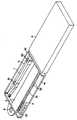
図2及び図3は、本発明の収納ケースの第二の具体例を示す。この収納ケースは、概略矩形の板状体41を備え、該板状体41は、その3辺に沿って立設された側壁42を備えて全体としてトレー状に成形されている。さらに、板状体41は、残りの1辺、すなわち、側壁42を備えない辺(以下、「前方辺」という)から僅かな間隔をおいて平行に延在する帯状の隆起部を備えている。板状体41の前方辺に隣接する該隆起部の端面によって段部31が形成され、段部31は、その長手方向に沿って一列に整列された多数の開口32を備えている。該開口32は、図1におけると同様の寸法を備えている。したがって、ブラシ2の先端部を開口32に挿入してその基端部の台座を段部31に当接させることにより、ブラシ2を収容することができ、これにより、ブラシ収容部3を構成している。この段部31は、板状体41をブロー成形やプレス成形等によって折り曲げることによって形成してもよく、また、端面で開口する多数の孔部を備えた帯状のブロック部材を、板状体41の上面に成形または接着することにより形成してもよい。
【0020】
さらに、板状体41は、段部31と反対の側に、ハンドル収容部5を備えている。ハンドル収容部5は、ハンドルを挟持して固定するホルダー部51,52を備えている。このホルダー部51,52の夫々は、板状体41から垂直に立設された一対の対向する突出片からなり、その先端に拡大部を備えているため、スナップ式にハンドルを着脱することができる。なお、この収容ケースは、蓋体6を備えてもよく、図1の具体例に関連して述べた形式の蓋体6以外に、図2に示されるような、外箱によって蓋体6を構成してもよい。また、この収納ケースは、板状体41の一辺にハンギングループ8を備えることができ、販売時などにフックに吊るして陳列できるようにされている。
【0021】
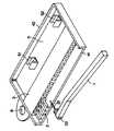
この収納ケースは、使用時、図3に示されるように、蓋体6を除去すると、板状体41の前方辺から、開口32に収容されたブラシ2の基端部22に容易に接近できるため、一方の手で収容ケースを保持し、片方の手でハンドル1を持って、ブラシ2を直接手で触れることなくハンドル1に簡単に装着することができる。
【0022】
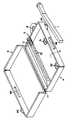
図4及び図5は、本発明の第三の具体例を示す。この収納ケースは、上面が開口した箱形の本体4を備え、また、本体4の一辺に沿って設けられた連接部71を介して本体4に対して開閉自在に連接された蓋体6を備えている。該本体4は連接部71と反対側の側壁の外面に凸部48を備え、蓋体6の側壁には、これを本体4に閉止した時に凸部48に係合するスロット68が設けられており、これにより、不意に収納ケースが開くことを防止している。なお、本体4と蓋体6は、側壁の外面に張出部49,69をそれぞれ備えており、開閉を容易にしている。
【0023】
さらに、この収納ケースは、ブラシ収容部3として、帯状のブロック部材を備えている。このブロック部材には、その端面で開口する断面円形の多数の孔部が、長手方向に沿って一列に整列して形成されている。当該孔部は、開口32が形成された端面から他方の端面に貫通する貫通孔であってもよく、また、盲孔であってもよい。当該開口32の直径は、ブラシ2の先端部21の最大外径にほぼ等しく、ブラシ2の基端部22を構成する台座の外径よりも小さいため、ブラシ2の先端部21を開口32から孔部へ挿入することにより、ブラシ2の基端部22を外方に突出させて収容することができる。
【0024】
図5に示されるように、このブラシ収容部3は、その長手方向軸の回りに回動可能なように本体4に取り付けられている。すなわち、図示の例では、本体4は、連接部71に直交する2つの側壁の内面に、該連接部71に隣接して配置された半球状の突起43を備えており、ブラシ収容部3の帯状部材の両端部には、開口32と反対側の端面寄りの位置に、該突起43に嵌合する凹部33を備えている。したがって、ブラシ収容部3の凹部33を突起43に嵌合させて本体4に取り付けることにより、ブラシ収容部3は、本体4に対して揺動できる。
【0025】
さらに、本体4は、連接部71と反対側の領域に、ハンドルのホルダー部51,52を備え、ハンドル収容部5を形成している。このホルダー部51,52は、断面概略U字状の形状を備え、図2及び図3におけるホルダー部と同様に、スナップ式にハンドル1を収容することができる。
【0026】
使用時、スロット68と凸部48の係合を解除して蓋体6を開く。そして、ハンドル1をホルダー部51,52から取り出し、ブラシ収容部3を上記凹部33と突起43からなる軸線の回りに蓋体6の方向に回転させると、該ブラシ収容部3の開口32が上向きになるとともに、それに収容されたブラシ2の基端部22が上向きになる。したがって、基端部22にハンドル1を容易に接近させることができるため、ブラシ2を直接手で触れることなくハンドル1に容易に装着できる。
【0027】
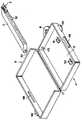
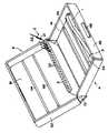
図6及び図7は、本発明の第四の具体例を示す。この収容ケースは、本体4と蓋体6とを備え、両者は何れも、概略矩形の板状体41,61と、その3辺に沿って立設された側壁42,62とを備えてなる。そして、本体4と蓋体6とは、側壁を備えない辺に沿って折畳み可能に連接された背板72を介して接続されている。図7から明らかなように、背板72の幅Hは、本体4及び蓋体6の側壁の高さとほぼ同じ寸法される。蓋体6は、その内寸法が、本体4の外寸法よりも僅かに大きくされており、閉止時、本体4の外側に嵌着し、図5と同様に、スロット68と凸部48との係合によって、容易にケースが開くのを防止する。
【0028】
この収容ケースは、上記第三の具体例と同様のブロック部材からなるブラシ収容部3を備えているが、当該ブロック部材は、開口32が形成された端面と反対側の端面で背板72に取り付けられている点に特徴を有する。したがって、使用時、蓋体6を本体4から開いた時、図6に示されるように、背板72も本体4から離れる方向に開くため、ブラシ収容部3の開口32が上向きになり、そこに収容されたブラシ2の基端部22も上を向く。したがって、該基端部22にハンドル1を容易に接近させることができるため、歯間ブラシ2を直接手で触れることなくハンドル1に容易に装着することができる。なお、ブラシ収容部3は、背板72に固着してもよく、また、各種の寸法のブラシの収容に容易に対応できるように、着脱自在に背板72に取り付けてもよい。
【0029】
この収容ケースは、本体4と蓋体6の板状体41,61の内面に、背板71と概略平行に延在するリブ44,64を夫々備えている。リブ44は、凸部48が設けられた側壁に隣接した本体4の領域にハンドル収容部5を画定する。図7から明らかなように、リブ64は、蓋体6を閉止した時、本体4のリブ44と対向する位置に設けられており、その際、リブ44とリブ64との間に形成される隙間は、ハンドル1の厚さよりも小さくされている。したがって、ハンドル収容部5にハンドル1を収容してケースを閉止すれば、ハンドル1がブラシ収容部3の方向に移動することが阻止され、ハンドル1とブラシ2とが衝突してブラシ2の基端部22を損傷することが防止される。
【0030】
さらに、この収容ケースは、別のリブ45及びリブ65を本体4と蓋体6の内面に夫々備えている。これらのリブ45,65も、蓋体6を閉止した時に、互いに対向する位置に設けられている。図7から明らかなように、リブ45とリブ65は、蓋体6の閉止時に、ブラシ収容部3の開口32から突出するブラシの基端部22を挟持してブラシの動きを制限する。したがって、この収容ケースにブラシ2を収容して搬送する場合などに、ブラシ2が開口32から抜け落ちてケース内で散乱することが防止される。これは、特に、基端部22が台座を備えず、単に軸体自体からなるような形式のブラシ2を収容する場合に好適である。なお、図1〜図5に示されるような基端部22に台座を備えたブラシを収容する場合は、当該リブ45,65は、基端部22の自由端に当接してブラシの動きを制限するように配置されてもよい。
【0031】
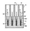
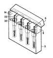
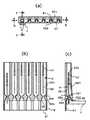
次に、図8を参照しつつ、本発明の第五の具体例について説明する。図8の具体例は、上記第三及び第四の具体例と同様のブロック部材からなるブラシ収容部3を備え、このブロック部材は、その端面に沿って一列に開口する断面円形の孔部(盲孔)を4つ備え、図6及び図7に示される形式のブラシを4本収容している。そして、該端面上には、樋形の4つの平行な溝91を備えた案内部材9が立設されている。各溝91は、各孔部の開口32と連通して、該孔部の軸線に沿って上方へ延在している。
【0032】
一般に、図6〜8に示される形式のブラシ2をハンドル1に装着するためには、ブラシ2の基端部22をハンドル1の先端に設けられた細孔へ、あたかも針孔に糸を通すような注意をしながら、挿入する必要があり、必ずしも容易でない。しかし、この具体例では、開口32から突出するブラシの基端部22は溝91で取り囲まれているため、ハンドル1の先端を溝91に沿って下げることにより、ハンドル1の先端の細孔がブラシの基端部22に案内されるため、お年寄りでもブラシの取り付け操作を容易に行えるようになり、好都合である。その後、ハンドル1に設けられたノブ11を摺動させて、ハンドル1の先端部の細孔に設けられた適当なブラシ固定手段を動作させて基端部22をハンドル1に固定すれば、歯間ブラシを使用できる状態となる。かかるブラシ固定手段を備えたハンドル1の詳細については、特願平11−87317号などを参照されたい。
【0033】
さらに、図8の収容ケースは、ブロック部材の端面の前方縁に沿って折り畳み式に連接された蓋体6を備えている。該蓋体6は案内部材9の溝部91を覆う形状を備えているので、該収容ケースを閉止して、輸送時にブラシ2が孔部から抜け出て散乱するのを防止できる。
【0034】
ブラシ2のハンドル1への装着を容易にするためには、ブラシ収容部3の孔部は、ブラシ2、特にその基端部22を孔部の軸線に沿って保持するようにすることが好ましい。そのために、図9に示されるように、孔部は、開口32に隣接する上部32aを内径が大きな円筒状とし、下部32bを上部32aと同軸の内径が小さな円筒状にするとよい。特に下部32bの内径は、ブラシ2の先端部21の最大径とほぼ等しくすることが好ましい。この場合、ブラシ2の基端部22は開口32の中心付近から溝91内に延在するので、ハンドル1の先端部に装着しやすくなる。別法として、孔部は、図10に示されるように、開口32から下方へ向けて窄まった逆円錐台形状の孔32cであってもよい。さらに、溝91を同様の逆円錐台形状としてもよく、この場合、ブラシ2の装着時、ハンドル1の先端を溝91に沿って下降させるに従い、該先端が基端部22の方向に誘導されるので好都合である。
【0035】
また、図11に示されるように、ブラシ2を収容する孔部に、上部32aと下部32bとの間に狭窄部32dを設けることによって、ブラシ2の基端部22を開口32の中央に保持するようにしてもよい。この場合、輸送時などの振動で、ブラシ2が収容ケースから抜け出ることも防止される。この具体例の場合、図11から明らかなように、成形加工の容易さの観点から、孔部の上部32aと狭窄部32dを案内部材9と一体に成形し、下部32bを包含する残りの部分を別に成形することが好ましい。この時、狭窄部32dの下部32bに対向する開口周辺に、下部32bに嵌合する突部32eを形成すると、組立作業が容易に行えるので好都合である。また、図11の収容ケースを構成する上記2つの部品は、後述する図12〜13の具体例のように、互いに対向する縁端に沿って2つ折り可能に連接されてもよい。
【0036】
図12は、上記第五の具体例の変形例を示す。図12から明らかなように、この変形例では、ブラシ収容部3と案内部材9とが、収容部3の上端面の一辺に沿って二つ折り可能に接続されている。したがって、案内部材9を使用する場合は、案内部材9を起こして図8のような状態で使用することが可能であり、また、案内部材9の使用を望まない場合は、ブラシ収容部3の端面から案内部材9を倒しておくことができる。また、図13に示されるように、ブラシ収容部3と案内部材9を折り畳んで背中合わせとし、矩形の蓋体6を被せることにより、コンパクトに包装することができる。この時、収容部3の底面と案内部材9の端面とにそれぞれ張出部39及び92を設け、蓋体6を閉じたとき、その開口縁が張出部39及び92に当接するようにすると、収容部3に収容されたブラシ2の基端部22が蓋体6の上壁で押しつぶされるのを防止できる。また、適宜、蓋体6は、収容部3又は案内部材9とスナップ式に嵌合するようにしてもよい。
【0037】
図14は、上記第五の具体例の別の変形例を示す。この変形例は、案内部材9の高さが図8の具体例よりも低く、蓋体6が、案内部材9の後方壁、すなわち溝91の裏側の面に折畳み可能に取り付けられている点で、図8の具体例と異なる。図14の変形例では、通常は蓋体6を案内部材9に被せておき、使用時に蓋体6を開き、ハンドル1の先端部を案内部材9の溝91に案内させてブラシ2を容易に取り付けることができる。
【0038】
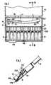
図15は、本発明の収容ケースの第六の具体例を示す。この具体例は、概略矩形の箱型の本体4を備え、該本体4内は、ハンドル収容部5とブラシ収容部3とに仕切られている。ハンドル収容部5は、前述の具体例と同様に、ホルダー部51,52を備えて、ハンドル1を収容できるようにされている。ブラシ収容部3は、その長手方向に沿って多数の凹部32を備えたリブが形成されている。従って、図15(b)から明らかなように、ブラシの基端部22を該凹部32に載置し、先端部21を本体4の底面に載置することによって、各ブラシの基端部22を斜め上方に向けて保持することができる。さらに、該凹部32のそれぞれは、凹部32に保持されたブラシ基端部22を取り囲むように配置された溝91を備えている。該溝91は、凹部32に保持されたブラシ基端部22と概略平行して延在しているので、ハンドル1の先端部を該溝91に案内させて動かすことにより、基端部22をハンドル1先端部の細孔に挿入することが可能となり、容易にブラシをハンドル1に装着することができる。なお、該本体1は、図示のように、図4及び5の具体例と同様の蓋体6が連接されていてもよい。本具体例の構成は、プレス成形、射出成形等によって簡単に製造できる点で有利である。なお、本体1は、図示の蓋体6の代わりに、別体の蓋体を備えても良く、または、ブリスターパッケージによる包装をすることもできる。
【0039】
図16は、本発明の収容ケースの第七の具体例を示す。この具体例は、図16(b)から明らかなように、基本的には、図11の具体例と類似の構成を備えている。すなわち、ブラシ2を収容する孔部は、上部32aと下部32bとの間に狭窄部32dを備え、また、開口32の上方には、各開口32に対応した案内溝91を備えた案内部材9を備えている。しかし、この具体例は、下部32bの寸法を、ブラシ2全体を収容する寸法とし、開口32を開閉自在とし、開口32の開口時にブラシ2の基端部22を挿通させるようにしている点で、図11の具体例と異なる。すなわち、この具体例では、開口32を開閉自在とするために、図16(a)及び(c)から明らかなように、各孔部は、開口32から上部32a及び狭窄部32dを経て下部32bへ向けて、溝92と同様に側方へ開口する溝部と、該溝部の長手方向開口を被覆する帯状カバー320とからなる。この帯状カバー320は、可撓性の材料から構成され、下部32b側にて固定され、開口32側の端部は自由端とされ、板ばねのように作用する。この帯状カバー320は、上部32a及び狭窄部32dにおいて、その溝部に向けて突出する閉止片321を備え、これにより、下部32bに収容されたブラシ2が開口32から抜け出すのを防止している。図16(c)から明らかなように、閉止片321は、上部32aから下部32bに向けて次第に溝内に進入する傾斜面322を備えている。
【0040】
次に、図17を参照しつつ、図16の使用例を説明する。図16の収容ケースは、使用時、開口32を下方に向けて使用すると好都合である。すなわち、図17(a)及び(c)に示されるように、ハンドル1の先端部を溝91に案内させて、開口32に挿入する。そうすると、ハンドル1の先端部が閉止片321の傾斜面322に当接する。さらに、ハンドル1の先端部を開口32へ押し込むと、帯状カバー320の自由端が外方に撓むとともに、閉止片321が溝部から離隔する。この状態で、図17(b)及び(c)に示されるように、収容ケースとハンドル1とを上下逆さにすると、重力に従い、ブラシ2の基端部22が狭窄部32dと上部32aを通過し、開口32に配置されたハンドル1の細孔内に落下する。なお、図示のように、下部32bは、狭窄部32dに隣接する領域で、該狭窄部32dに向けて窄まった漏斗状に形成されているので、この領域でブラシ2の基端部22が狭窄部32dに案内され、狭窄部32dで詰まることが防止されている。かくして、この具体例によれば、基端部22に台座を備えない形式のブラシ2であっても、ハンドル1への装着をきわめて容易に行える。また、この収容ケースは、図4乃至図6に示されるような蓋体と本体とからなる2つ折りのケースに収容したり、その蓋体または本体に取り付けてもよい。
【0041】
なお、上述の各種具体例において、ブラシ収容部に通気性が必要な場合は、ブラシ収容部に通気孔を設けたり、通気性の良好な材質を用いて構成することができ、また、衛生上の必要があれば、抗菌性の材質を用いて構成することもでき、その他同様に、必要に応じて、材質や形状を変化させることができることは言うまでもない。また、板状体41や蓋体6などの面に鏡を付したり、使用上の注意を記載したシートを貼り付けたり、直接印刷したりしてもよいし、意匠性を高めるために装飾等を施すこともできる。
【0042】
【発明の効果】
本発明によれば、小さなスペースに多数の歯間清掃用のブラシを整頓して収容することが可能な歯間ブラシ収容ケースが提供されるだけでなく、このケースにブラシを収容することにより、ブラシの基端部にハンドルを近づけて、先端部に手で触れることなく、容易にハンドルへブラシを装着できるため、操作面及び衛生面の両面でも優れており、また、携帯するのにも便利である。
【図面の簡単な説明】
【図1】本発明の収容ケースの第一の具体例を示す斜視図である。
【図2】本発明の収容ケースの第二の具体例を示す斜視図である。
【図3】図2の収容ケースの使用例を示す斜視図である。
【図4】本発明の収容ケースの第三の具体例を示す斜視図である。
【図5】図4の収容ケースの分解図である。
【図6】本発明の収容ケースの第四の具体例を示す斜視図である。
【図7】図6の収容ケースを、蓋体を閉じた状態で示す、中央部側断面図である。
【図8】本発明の収容ケースの第五の具体例を示す斜視図である。
【図9】図8のIX-IX線に沿った縦断面図である。
【図10】図8の具体例の変形例を示す図9と同様の図である。
【図11】図8の具体例の別の変形例を示す図9と同様の図である。
【図12】図8の具体例の別の変形例を示す斜視図である。
【図13】図12の具体例を覆蓋状態で示す斜視図である。
【図14】図8の具体例のさらに別の変形例を示す斜視図である。
【図15】 (a)は本発明の第六の具体例を示す平面図であり、(b)は(a)のb-b線に沿った断面図である。
【図16】 (a)は本発明の第七の具体例を示す平面図であり、(b)は(a)のb-b線に沿った断面図、(c)は(a)のc-c線に沿った断面図である。
【図17】 (a)、(b)及び(c)は、それぞれ、図16の具体例を使用状態で示す図16と同様の図である。
【符号の説明】
1 ハンドル
11 ノブ
2 ブラシ
21 先端部
22 基端部
3 ブラシ収容部
31 段部
32 開口
32a 上部
32b 下部
32c 逆円錐台形状の孔
32d 狭窄部
33 凹部
39 張出部
4 本体
41 板状体
42 側壁
43 突起
44,45 リブ
48 凸部
5 ハンドル収容部
51,52 ホルダー部
6 蓋体
61 板状体
62 側壁
64,65 リブ
68 スロット
71 連接部
72 背板
8 ハンギングループ
9 案内部材
91 溝
92 張出部
132 凹部[0001]
BACKGROUND OF THE INVENTION
The present invention relates to a housing case for interdental cleaning brushes, and in particular, can accommodate a plurality of brushes that are detachably attached to the handle and can be easily attached to the handle while the brush is stored. Regarding the storage case.
[0002]
[Prior art]
Conventionally, the interdental brush has been integrally fixed to the tip of the handle, but in recent years, a brush that is detachable from the handle so that the brush can be exchanged is becoming mainstream.
[0003]
In general, interdental brushes in which such brushes can be exchanged are sold as a set of one handle and several replacement brushes. In the packaging form, a bulge having a contour corresponding to the shape of the handle and the replacement brush is formed on the plastic sheet, and after the handle and the exchange brush are individually stored in the bulge, the flatness of the plastic sheet is set. It is common to use a so-called blister package in which paperboard is heat-sealed on the part.
[0004]
In addition, a plurality of replacement brushes are packaged and sold, but the packaging form is mostly a blister package as well.
[0005]
[Problems to be solved by the invention]
However, in the case of the above packaging form, the size of the bulge formed on the plastic sheet to accommodate one replacement brush is considerably larger than the actual size of the replacement brush, and is included in one blister package. There is a limit to the number of replacement brushes that can be made.
[0006]
Moreover, in order to take out the handle and the replacement brush from the blister package, it is necessary to tear the paperboard. After that, when the remaining replacement brushes are stored, they are placed on a shelf or the like together with the torn package, which is unsightly.
[0007]
Furthermore, when taking out the replacement brush from the package, the brush may be directly touched by hand, which is not preferable for hygiene.
[0008]
An object of the present invention is to provide a housing case for an interdental cleaning brush that not only can accommodate a large number of replacement brushes, but also can be easily attached to a handle, and is excellent in appearance. .
[0009]
[Means for Solving the Problems]
ADVANTAGE OF THE INVENTION According to this invention, the interdental brush accommodation case provided with the brush accommodating part which can accommodate multiple brushes for interdental cleaning is provided. The brush housing portion projects the proximal end portion while allowing the distal end portion of the brush having a distal end portion used for cleaning between teeth and a proximal end portion to be gripped by hand or connected to the handle to be inserted. A plurality of openings are provided, and the plurality of openings are arranged in a row. Here, the row of openings can be linear, arcuate, staggered, or the like.
[0010]
Specifically, the brush housing portion of the housing case includes, for example, a belt-shaped step portion formed so as to protrude from the upper surface of the plate-like body, and a plurality of openings are arranged along the longitudinal direction of the step portion. Can be formed. Alternatively, the brush housing portion can be formed of a band-shaped block member in which a large number of holes having openings on the end surface are formed along the longitudinal direction. In addition to the brush accommodating portion, the accommodating case is advantageously provided with a handle accommodating portion.
[0011]
In addition, the storage case may be covered with a plastic sheet or the like in a state where the brush is inserted and stored in the opening of the brush storage portion, and may be opened and closed by providing a lid. Also good.
[0012]
Thus, according to the interdental brush accommodation case of the present invention, not only can a large number of interdental brushes be accommodated in a small space, but the proximal end portion of the accommodated brush can be easily accommodated from the outside. Since it can be accessed, it can be easily attached to the handle without touching the tip of the brush, and it is also excellent in terms of hygiene.
[0013]
DETAILED DESCRIPTION OF THE INVENTION
Hereinafter, the interdental brush storage case of the present invention will be described based on specific examples with reference to the drawings, but the present invention is not limited to the illustrated specific examples.
[0014]
FIG. 1 shows a first specific example of the storage case of the present invention. The storage case includes a substantially rectangular plate-
[0015]
As is well known, the
[0016]
Since the diameter of the
[0017]
Thus, since the storage case of this invention hold | maintains the
[0018]
In addition, this storage case can be closed with the
[0019]
2 and 3 show a second specific example of the storage case of the present invention. The storage case includes a substantially rectangular plate-
[0020]
Further, the plate-
[0021]
In use, the storage case can be easily accessed from the front side of the plate-
[0022]
4 and 5 show a third specific example of the present invention. The storage case includes a box-shaped
[0023]
Further, the storage case includes a band-shaped block member as the
[0024]
As shown in FIG. 5, the
[0025]
Further, the
[0026]
In use, the
[0027]
6 and 7 show a fourth specific example of the present invention. The housing case includes a
[0028]
The housing case includes a
[0029]
The housing case includes
[0030]
Further, the housing case includes another
[0031]
Next, a fifth example of the present invention will be described with reference to FIG. The specific example of FIG. 8 includes a brush
[0032]
Generally, in order to attach the
[0033]
Further, the housing case of FIG. 8 includes a
[0034]
In order to facilitate attachment of the
[0035]
Further, as shown in FIG. 11, the
[0036]
FIG. 12 shows a modification of the fifth specific example. As is clear from FIG. 12, in this modification, the
[0037]
FIG. 14 shows another modification of the fifth specific example. In this modification, the height of the
[0038]
FIG. 15 shows a sixth specific example of the housing case of the present invention. This specific example includes a substantially rectangular box-shaped
[0039]
FIG. 16 shows a seventh example of the storage case of the present invention. As is clear from FIG. 16B, this specific example basically has a configuration similar to the specific example of FIG. In other words, the hole that accommodates the
[0040]
Next, a usage example of FIG. 16 will be described with reference to FIG. In the case of use, the housing case of FIG. 16 is conveniently used with the
[0041]
In the above-described various specific examples, when the brush housing portion needs air permeability, the brush housing portion can be provided with a vent hole, or can be configured using a material having good air permeability. Needless to say, it is possible to use an antibacterial material, and similarly, the material and shape can be changed as necessary. In addition, a mirror may be attached to the surface of the plate-
[0042]
【The invention's effect】
According to the present invention, not only is an interdental brush housing case capable of accommodating a large number of interdental cleaning brushes in a small space, but also by accommodating the brushes in this case, The handle is close to the base end of the brush, and the brush can be easily attached to the handle without touching the tip, so it is excellent in terms of both operation and hygiene, and convenient to carry It is.
[Brief description of the drawings]
FIG. 1 is a perspective view showing a first specific example of a storage case according to the present invention.
FIG. 2 is a perspective view showing a second specific example of the storage case of the present invention.
3 is a perspective view showing an example of use of the storage case of FIG. 2. FIG.
FIG. 4 is a perspective view showing a third specific example of the housing case of the present invention.
5 is an exploded view of the storage case of FIG. 4. FIG.
FIG. 6 is a perspective view showing a fourth specific example of the housing case of the present invention.
7 is a central side sectional view showing the housing case of FIG. 6 with the lid closed. FIG.
FIG. 8 is a perspective view showing a fifth specific example of the housing case of the present invention.
9 is a longitudinal sectional view taken along line IX-IX in FIG.
10 is a view similar to FIG. 9 showing a modification of the specific example of FIG. 8;
FIG. 11 is a view similar to FIG. 9 showing another modification of the specific example of FIG. 8;
12 is a perspective view showing another modified example of the specific example of FIG. 8. FIG.
13 is a perspective view showing a specific example of FIG. 12 in a cover state. FIG.
14 is a perspective view showing still another modified example of the specific example of FIG. 8. FIG.
15A is a plan view showing a sixth specific example of the present invention, and FIG. 15B is a cross-sectional view taken along line bb of FIG. 15A.
16 (a) is a plan view showing a seventh specific example of the present invention, (b) is a cross-sectional view taken along line bb of (a), and (c) is taken along line cc of (a). FIG.
17 (a), (b) and (c) are views similar to FIG. 16 showing the specific example of FIG. 16 in use.
[Explanation of symbols]
1 Handle
11 Knobs
2 brushes
21 Tip
22 Base end
3 Brush housing
31 steps
32 opening
32a upper part
32b bottom
32c inverted frustoconical hole
32d stenosis
33 recess
39 Overhang
4 Body
41 Plate
42 side wall
43 Protrusions
44, 45 ribs
48 Convex
5 Handle housing
51, 52 Holder part
6 Lid
61 Plate
62 side wall
64,65 ribs
68 slots
71 connection
72 Backboard
8 Hanging loop
9 Guide members
91 groove
92 Overhang
132 recess
Claims (11)
Translated fromJapanesePriority Applications (1)
| Application Number | Priority Date | Filing Date | Title |
|---|---|---|---|
| JP16196199AJP4317612B2 (en) | 1999-02-04 | 1999-06-09 | Interdental brush housing case |
Applications Claiming Priority (5)
| Application Number | Priority Date | Filing Date | Title |
|---|---|---|---|
| JP2797599 | 1999-02-04 | ||
| JP11-101810 | 1999-04-08 | ||
| JP11-27975 | 1999-04-08 | ||
| JP10181099 | 1999-04-08 | ||
| JP16196199AJP4317612B2 (en) | 1999-02-04 | 1999-06-09 | Interdental brush housing case |
Publications (2)
| Publication Number | Publication Date |
|---|---|
| JP2000350612A JP2000350612A (en) | 2000-12-19 |
| JP4317612B2true JP4317612B2 (en) | 2009-08-19 |
Family
ID=27286024
Family Applications (1)
| Application Number | Title | Priority Date | Filing Date |
|---|---|---|---|
| JP16196199AExpired - Fee RelatedJP4317612B2 (en) | 1999-02-04 | 1999-06-09 | Interdental brush housing case |
Country Status (1)
| Country | Link |
|---|---|
| JP (1) | JP4317612B2 (en) |
Cited By (1)
| Publication number | Priority date | Publication date | Assignee | Title |
|---|---|---|---|---|
| CN103140187A (en)* | 2010-09-21 | 2013-06-05 | 口腔护理股份有限公司 | Flossing system |
Families Citing this family (8)
| Publication number | Priority date | Publication date | Assignee | Title |
|---|---|---|---|---|
| JP4732914B2 (en)* | 2006-02-10 | 2011-07-27 | 株式会社まめいた | Interdental brush container |
| USD571558S1 (en)* | 2006-08-01 | 2008-06-24 | Pierre Fabre Medicament | Set of interproximal brushes with case |
| JP5774955B2 (en)* | 2011-09-30 | 2015-09-09 | 株式会社ジーシー | Interdental brush body storage case |
| JP6215166B2 (en)* | 2014-09-26 | 2017-10-18 | デンタルプロ株式会社 | Interdental brush case |
| CH714044A1 (en)* | 2017-08-04 | 2019-02-15 | Curaden Ag | Container with interdental brushes. |
| EP3586792B1 (en)* | 2018-06-28 | 2021-05-26 | Curaden AG | Dental apparatus for probing spaces between teeth |
| WO2020130758A1 (en)* | 2018-12-21 | 2020-06-25 | 송소영 | Modular brush |
| KR102790537B1 (en)* | 2023-01-31 | 2025-04-02 | 동의대학교 산학협력단 | Portable dental kit |
- 1999
- 1999-06-09JPJP16196199Apatent/JP4317612B2/ennot_activeExpired - Fee Related
Cited By (2)
| Publication number | Priority date | Publication date | Assignee | Title |
|---|---|---|---|---|
| CN103140187A (en)* | 2010-09-21 | 2013-06-05 | 口腔护理股份有限公司 | Flossing system |
| CN103140187B (en)* | 2010-09-21 | 2016-01-27 | 口腔护理股份有限公司 | flossing system |
Also Published As
| Publication number | Publication date |
|---|---|
| JP2000350612A (en) | 2000-12-19 |
Similar Documents
| Publication | Publication Date | Title |
|---|---|---|
| US7815070B2 (en) | Wipes container particularly configured to be retained in outerwear, bags and other gear | |
| JP4656397B2 (en) | Powder container | |
| JP4317612B2 (en) | Interdental brush housing case | |
| JP2003137366A (en) | Article taking out container | |
| JP2009502550A (en) | Activity center | |
| JPH07206055A (en) | Container for wet tissue paper | |
| JP2000177774A (en) | Toothbrush case | |
| US5996803A (en) | Infant products organizer | |
| JP4732914B2 (en) | Interdental brush container | |
| JP4630711B2 (en) | Wet material storage container and wet tissue package | |
| JP3751451B2 (en) | Pouch stand with paper | |
| JP3823260B2 (en) | Compact container | |
| JP4475530B2 (en) | Suction powder dispenser | |
| JP2002037355A (en) | Outer packaging cover for box-like object | |
| JP2599370Y2 (en) | Brush holder | |
| CN213503997U (en) | bag storage box | |
| JP4771728B2 (en) | Wet material storage container and wet tissue package | |
| JPH0847418A (en) | Refillable container | |
| JP4481973B2 (en) | Wet tissue container with placement tool and wet tissue container placement tool | |
| JP2545355Y2 (en) | Inkstone storage case | |
| JPH0731773Y2 (en) | Intraocular lens case | |
| JP2000093220A (en) | Bag | |
| JP3012403U (en) | Tissue paper storage box | |
| JP4526798B2 (en) | Hairpin case holder | |
| JPH0445619Y2 (en) |
Legal Events
| Date | Code | Title | Description |
|---|---|---|---|
| A621 | Written request for application examination | Free format text:JAPANESE INTERMEDIATE CODE: A621 Effective date:20051208 | |
| A977 | Report on retrieval | Free format text:JAPANESE INTERMEDIATE CODE: A971007 Effective date:20080811 | |
| A131 | Notification of reasons for refusal | Free format text:JAPANESE INTERMEDIATE CODE: A131 Effective date:20080826 | |
| A521 | Written amendment | Free format text:JAPANESE INTERMEDIATE CODE: A523 Effective date:20081027 | |
| TRDD | Decision of grant or rejection written | ||
| A01 | Written decision to grant a patent or to grant a registration (utility model) | Free format text:JAPANESE INTERMEDIATE CODE: A01 Effective date:20090512 | |
| A01 | Written decision to grant a patent or to grant a registration (utility model) | Free format text:JAPANESE INTERMEDIATE CODE: A01 | |
| A61 | First payment of annual fees (during grant procedure) | Free format text:JAPANESE INTERMEDIATE CODE: A61 Effective date:20090525 | |
| R150 | Certificate of patent or registration of utility model | Free format text:JAPANESE INTERMEDIATE CODE: R150 | |
| FPAY | Renewal fee payment (event date is renewal date of database) | Free format text:PAYMENT UNTIL: 20120529 Year of fee payment:3 | |
| LAPS | Cancellation because of no payment of annual fees |