JP4317341B2 - Safety-related automation bus system - Google Patents
Safety-related automation bus systemDownload PDFInfo
- Publication number
- JP4317341B2 JP4317341B2JP2001505254AJP2001505254AJP4317341B2JP 4317341 B2JP4317341 B2JP 4317341B2JP 2001505254 AJP2001505254 AJP 2001505254AJP 2001505254 AJP2001505254 AJP 2001505254AJP 4317341 B2JP4317341 B2JP 4317341B2
- Authority
- JP
- Japan
- Prior art keywords
- safety
- data
- bus
- analyzer
- automation system
- Prior art date
- Legal status (The legal status is an assumption and is not a legal conclusion. Google has not performed a legal analysis and makes no representation as to the accuracy of the status listed.)
- Expired - Lifetime
Links
- 238000000034methodMethods0.000claimsdescription56
- 230000008569processEffects0.000claimsdescription29
- 230000006870functionEffects0.000claimsdescription26
- 238000012545processingMethods0.000claimsdescription17
- 230000004044responseEffects0.000claimsdescription10
- 238000012544monitoring processMethods0.000claimsdescription9
- 238000004886process controlMethods0.000claimsdescription7
- 231100000279safety dataToxicity0.000claimsdescription6
- 238000013461designMethods0.000claimsdescription5
- 230000005540biological transmissionEffects0.000description8
- 238000010586diagramMethods0.000description6
- 238000005516engineering processMethods0.000description6
- 238000011156evaluationMethods0.000description4
- 230000008859changeEffects0.000description3
- 238000012360testing methodMethods0.000description3
- 238000003466weldingMethods0.000description3
- 238000013459approachMethods0.000description2
- 230000004888barrier functionEffects0.000description2
- 238000012546transferMethods0.000description2
- 230000009471actionEffects0.000description1
- 230000008901benefitEffects0.000description1
- 230000006378damageEffects0.000description1
- 230000001419dependent effectEffects0.000description1
- 238000011161developmentMethods0.000description1
- 230000018109developmental processEffects0.000description1
- 238000009776industrial productionMethods0.000description1
- 230000000977initiatory effectEffects0.000description1
- 230000010354integrationEffects0.000description1
- 238000012423maintenanceMethods0.000description1
- 238000012986modificationMethods0.000description1
- 230000004048modificationEffects0.000description1
- 230000002093peripheral effectEffects0.000description1
- 230000035484reaction timeEffects0.000description1
- 230000009467reductionEffects0.000description1
- 238000000926separation methodMethods0.000description1
- 238000003860storageMethods0.000description1
- 230000001960triggered effectEffects0.000description1
Images


Classifications
- H—ELECTRICITY
- H04—ELECTRIC COMMUNICATION TECHNIQUE
- H04L—TRANSMISSION OF DIGITAL INFORMATION, e.g. TELEGRAPHIC COMMUNICATION
- H04L12/00—Data switching networks
- H04L12/28—Data switching networks characterised by path configuration, e.g. LAN [Local Area Networks] or WAN [Wide Area Networks]
- H04L12/40—Bus networks
- H04L12/40006—Architecture of a communication node
- H04L12/40032—Details regarding a bus interface enhancer
- G—PHYSICS
- G05—CONTROLLING; REGULATING
- G05B—CONTROL OR REGULATING SYSTEMS IN GENERAL; FUNCTIONAL ELEMENTS OF SUCH SYSTEMS; MONITORING OR TESTING ARRANGEMENTS FOR SUCH SYSTEMS OR ELEMENTS
- G05B9/00—Safety arrangements
- G05B9/02—Safety arrangements electric
- G05B9/03—Safety arrangements electric with multiple-channel loop, i.e. redundant control systems
- H—ELECTRICITY
- H04—ELECTRIC COMMUNICATION TECHNIQUE
- H04L—TRANSMISSION OF DIGITAL INFORMATION, e.g. TELEGRAPHIC COMMUNICATION
- H04L12/00—Data switching networks
- H04L12/28—Data switching networks characterised by path configuration, e.g. LAN [Local Area Networks] or WAN [Wide Area Networks]
- H04L12/40—Bus networks
- H04L12/40006—Architecture of a communication node
- H04L12/40013—Details regarding a bus controller
- H—ELECTRICITY
- H04—ELECTRIC COMMUNICATION TECHNIQUE
- H04L—TRANSMISSION OF DIGITAL INFORMATION, e.g. TELEGRAPHIC COMMUNICATION
- H04L12/00—Data switching networks
- H04L12/28—Data switching networks characterised by path configuration, e.g. LAN [Local Area Networks] or WAN [Wide Area Networks]
- H04L12/40—Bus networks
- H04L12/403—Bus networks with centralised control, e.g. polling
- H—ELECTRICITY
- H04—ELECTRIC COMMUNICATION TECHNIQUE
- H04L—TRANSMISSION OF DIGITAL INFORMATION, e.g. TELEGRAPHIC COMMUNICATION
- H04L69/00—Network arrangements, protocols or services independent of the application payload and not provided for in the other groups of this subclass
- H04L69/40—Network arrangements, protocols or services independent of the application payload and not provided for in the other groups of this subclass for recovering from a failure of a protocol instance or entity, e.g. service redundancy protocols, protocol state redundancy or protocol service redirection
Landscapes
- Engineering & Computer Science (AREA)
- Computer Networks & Wireless Communication (AREA)
- Signal Processing (AREA)
- Computer Security & Cryptography (AREA)
- Physics & Mathematics (AREA)
- General Physics & Mathematics (AREA)
- Automation & Control Theory (AREA)
- Safety Devices In Control Systems (AREA)
- Small-Scale Networks (AREA)
- Debugging And Monitoring (AREA)
- Bus Control (AREA)
- Air Bags (AREA)
Description
Translated fromJapanese【0001】
本発明は、請求項1の特徴記載部分で請求された安全関連オートメーション・バス・システムに関し、このようなシステムを操作するための方法に関する。
【0002】
制御およびデータ伝送システムは、高レベルのオートメーションを可能にするので、工業生産だけでなく優位な地位を得ている。一般にこのようなオートメーション・システムは、少なくとも安全に関してより厳しい要件が課せられる可能性のあるセクションまたはコンポーネントを有する。たとえば、所定の動作パラメータ内で所与のマシンを操作していることを確認する必要があるか、または誰かがその動作エリア内にいるときでもマシンが動作しないようにする必要がある。このような状況では、たとえば、旋盤が所定の回転速度を超えないようにしなければならないか、またはロボットを操作しているときはそのロボットの行動半径内に誰もいないようにしなければならない。さらに、オートメーション・システムを操作しているときは、システム内の1つのコンポーネントが故障した場合に、そのシステムが未定義の状態、したがって予測できない状態に変化しないことを確認する必要がある。
【0003】
従来技術によるこの問題への取り組み方の1つは、特に、システム内の安全関連コンポーネントのために複数のチャネルを使用すること、すなわち、このようなコンポーネントが冗長になるように設計することである。たとえば、安全バス・コンポーネント、すなわち、たとえば安全関連マシンに関連するバス利用部分をオートメーション・バス・システム内で二重にすることができる。同時に、中央制御部およびバスは、複数のチャネルを有するかまたは特定の安全制御システムさえも有する可能性があるが、その安全制御システムはプロセス制御システムとは別のものであり、状況によっては、安全関連コンポーネントを制御するために冗長設計のものである。この安全制御システムは本質的に安全関連入力情報に関する論理リンクを実行し、その後、たとえばオートメーション・バスを介して安全関連論理リンク・データを出力コンポーネントに伝送する。出力コンポーネント自体は、受け取った安全対策を処理し、テスト結果が肯定である場合にこれを周辺装置に出力する。さらに、このようなコンポーネントは、障害を見つけたかまたは所定の期間内に有効なデータを受け取らなかった場合に、その出力を安全な状態に切り替える。
【0004】
しかし、2つの制御システム、すなわち、プロセス制御システムと上記の安全制御システムをこのシステム内で使用すると、いくつかの不都合が生じる。とりわけ、オートメーション・システムの反応時間に関する要件がますます厳しくなることは、このようなシステムをセーフティ・アイランド間に細分しなければならない場合が多くなることを意味する。さらに、特にマルチチャネル制御システムでは、システムが原則として無傷であるにもかかわらず、故障に至るかまたはマシン部品の破壊にすら至る可能性のある同期問題が発生する。さらに、マルチチャネル設計では、ハードウェアの複雑さが増すために、結果的にシステム・コストおよびメンテナンス・コストが増加する。
【0005】
DE 198 15 150 Alでは、バスに接続され、バス・システムを介して伝送される記号を連続的に監視し、バス・システムを介して伝送されるコーディングをエラーなしで識別したときだけ1つの機器を始動する評価ユニットを含むシステムを開示している。このために、バス利用部分によってマスタに送られる入力データを評価し、その評価に応答してその機器をオンまたはオフに切り替える。
【0006】
このような手法は最初に記載したシステムほど費用のかかるものではないが、システムのアップグレードまたはシステムと他のバス・コンポーネントとの整合に関して非常にフレキシビリティが低いものである。さらに、評価ユニットは安全ベースの機能の開始についてのみ責任を負うので、厳しい安全要件に従うためには評価ユニットが冗長設計のものであることが絶対に不可欠である。
【0007】
したがって、本発明の一目的は、可能な限りハードウェアの冗長性を必要とせず、それぞれの要件にフレキシブルに適合可能な安全関連オートメーション・バス・システムを提供することにある。
【0008】
本発明では、請求項1の特徴を有するオートメーション・バス・システムと、請求項14で請求され、このような制御およびデータ処理システムを操作するための方法により、この問題を解決する。本発明の発展例については従属クレームに明記する。
【0009】
本発明によれば、このオートメーション・システムは、バス・システムと、それに接続されたセンサおよびアクチュエータ・バス利用部分と、プロセスリンクの入出力データの処理によるプロセス制御機能および安全関連データの処理による安全関連制御機能すなわち安全関連の入力および出力の制御を実行する標準制御装置とを含む。また、これは安全分析器と呼ばれるものも含み、この分析器は適切なインタフェースによりバスに接続され、バスを介してデータ・フローを監視するが、安全関連機能を実行するようにセットアップされる。これは、たとえば、システム・コンポーネントへの供給電圧をオフにするための接触器の作動または品質データの決定に関連する。このような品質データとしては、一般的なシステム・パラメータ、たとえば、システム・コンポーネントでの障害の発生またはバス伝送エラーに関するデータを含む可能性がある。このオートメーション・システムは、標準制御装置がバスを介して少なくとも1つの安全関連出力を駆動するということによって特徴づけられるが、それ自体がこのような安全関連出力を有することもできる。本発明によれば、安全関連出力とは、安全情報の一機能として安全ベースのシーケンス、たとえば、マシンの減速または電源電力の遮断によるマシンのスイッチオフを開始する安全情報のシンクを意味する。本発明によるオートメーション・システム内の安全分析器は、バス・データストリーム内の安全関連データ、特に安全関連論理リンク・データをチェックおよび/または処理するために設計されている。この場合、安全関連論理リンク・データは、たとえば、安全関連データの処理後に安全関連制御システムが安全関連出力に送るデータである。
【0010】
したがって、オートメーション・システムに関するそれぞれの要件に極めてフレキシブルに適合可能なシステムを提供する。たとえば、安全バス・コンポーネントごとにこのような安全分析器を1つずつ割り振ることができ、個々の安全分析器がシステム内の複数の安全バス・コンポーネントまたはすべての安全バス・コンポーネントに関してバス・データストリーム内の安全関連データの処理または安全関連論理リンク・データのチェックを実行することも可能であるが、安全分析器自体を安全コンポーネントたとえば安全バス利用部分に統合することもできる。
【0011】
本発明の原理は、発明者の経験において、現在のオートメーション・システムで使用する電子機器自体がめったに故障しないという事実に基づくものである。従来技術による安全制御システムまたは安全バス・システムの形でオートメーション技術に現在のディジタル安全技術を統合すると、しばしば、システムのアベイラビリティが低下するという不都合が生じる。したがって、休止時間を短縮するために、上記の安全コンポーネントに加え、アベイラビリティ構造も使用するが、このような構造自体により、ハードウェアの複雑さが増すために、コストが少なからず増加することになる。
【0012】
したがって、本発明は、現在のオートメーション・システムの信頼性に基づくものであり、純粋な非常用電子機器またはソフトウェアを統合するが、これらは標準技術が不適切に動作しているときにのみシステムの動作に積極的に関わることになる。したがって、標準制御装置は安全関連データも処理し、すなわち、安全関連入力および出力を制御する。しかし、特に、バス・データストリーム内に生成される安全関連論理リンク・データは安全分析器によって監視され、チェックされる。これにより、もはやプログラミング中に回路技術と標準技術との厳密な分離を維持することが絶対に必要ではなくなるという利点がユーザにもたらされる。本発明によるオートメーション・システムは、バスを備えたすべてのシステム、特にマスタ/スレーブ・バス・アクセス方法を使用するバス・システム上で使用することができる。安全分析器を長距離バス・セクションに配置することとは無関係に、この安全分析器は、たとえばEN 50 254によるシリアル・バス・システム内のバス上のすべてのINデータを読み取ることができるが、監視可能なOUTデータの量はシステム内の安全分析器の配置によって決まる。この場合のバス・データストリームという表現は、本発明によれば、バスを介して伝送されるすべての情報を意味し、特に合計フレーム内でバスを介して移送されるデータを含む。
【0013】
関連の安全要件に従うために、安全分析器は、安全関連データ、特にバス・データストリーム内の論理リンク・データのチェックおよび/または処理に応答して、必要な安全関連機能を開始することができる。この場合、安全分析器は、OUTデータすなわち標準制御装置からの論理リンク・データだけでなく、INデータすなわち個々の入出力バス利用部分から標準制御装置に送られたバス・データストリーム内の情報にも反応することができる。
【0014】
バスを介して移送される安全関連論理リンク・データ内のエラーを識別するために、安全分析器は完全にプログラム可能な論理装置を有することができ、その装置では監視データ特に監視安全関連データが処理される。このため、標準制御システムの安全関連論理リンクをモデル化することにより、安全分析器は、バスを介してOUTデータとして送られたこの制御システムの論理リンク・データをチェックすることができ、このチェックまたは比較に応答して必要な安全関連機能を実行することができる。たとえば、システムを安全な状態に変更するために、安全分析器は、それを介してオートメーション・システム内のアセンブリ特にバス利用部分をオンまたはオフに切り替えることができる出力を有することもできる。このスイッチオフ・プロセスは、電圧供給から切断することによって実行することができる。相互に独立した関連バス利用部分をすべて安全な状態に変更するために、安全分析器は、バス・スパー、すなわち、互いに関連した複数のバス利用部分を含むセーフティ・アイランドをオフに切り替えるため、または分析器に記憶されたインタロック論理を基礎としてコンポーネントをオフに切り替えるようセットアップすることができる。しかし、安全分析器の安全関連出力を介してシステム全体を電圧供給から切断することも可能である。
【0015】
バスの監視に加え、安全分析器は直接入力を介して安全関連情報を検出することもでき、その直接入力により安全分析器はオートメーション・バス・システム内の安全関連装置に接続されている。この場合、この装置はバスに接続することができるが、その必要はない。一例として、このようにしてアクセス可能な安全関連情報は前述の旋盤の瞬間回転速度を含み、分析器出力は所定の限界回転速度を超えた場合にマシンをオフに切り替える。
【0016】
システム特に制御システム内の安全関連情報とプロセス・データを分離するために、バス・システムはインタフェース・アセンブリを介してホストに接続することができ、標準制御装置のプロセス関連制御はホスト内に配置され、標準制御装置の安全関連制御はインタフェース・アセンブリ内に配置される。たとえば、安全関連制御システムは、有利なことにソフトウェア機能モジュールの形にすることができ、このモジュールは安全関連入出力情報に関して必要な論理リンクを実行する。
【0017】
したがって、安全関連制御システムは、プロセス制御システムと同じように実現することができる。安全関連論理リンクをコーディングする場合、プログラマは、プロセス制御システムの場合と同じように、使用中のプログラミング言語とは無関係である。
【0018】
安全分析器内の論理リンクは、ホスト内およびインタフェース・アセンブリ内の論理リンクとほぼ同じ範囲を有し、同じプログラミング言語または異なるプログラミング言語で生成することができる。また、安全分析器は、ホスト・システムおよび/またはインタフェース・アセンブリからの結果とそれ自体の結果との間で論理リンクの比較を実行し、たとえば等しくない場合に安全ベースの機能を開始する。
【0019】
このようなシステムに関する受入れ手順は、従来技術によるシステムの場合よりかなり容易に実行することができる。このシステムは、安全技術をアクティブに切り替える必要なしに、すべての安全インタロックによって始動することができる。この場合、必要な論理リンクはホスト・システム内またはインタフェース・アセンブリ内に位置する。まず第一にブラックボックス・テストを使用して、このシステムの機能性を調査することができる。次に第2のステップでは、1つまたは複数の安全分析器の形で安全技術を接続する。プロセス・データ論理リンクではなく安全論理リンクだけが存在する場合、ホワイトボックス・テストを迅速かつ明瞭に実行することができ、その結果、受入れ時間をかなり短縮することができる。安全管理論理アルゴリズムはホスト・システムおよび/またはインタフェース・アセンブリ上でも実行できるので、分析器内のものとの比較を迅速に実行することができる。
【0020】
このバスがシリアル・リング・バス、たとえば、EN 50254によるバスであり、安全分析器がオートメーション・システムのトップレベルの長距離バス・セクションに配置されている場合、ここで言及するシステム内では各バス利用部分によって前方伝送線および戻り伝送線でデータが伝達されるので、このバスはシステム内のすべてのINデータにアクセスすることができる。したがって、分析器は、それがアクセスできるINデータとOUTデータに限定されたプロセス・マップを形成することができる。
【0021】
線形トポロジを備えたバス・システムでは、安全分析器は一般にバス・システム内のどのポイントでもすべての情報を読み取ることができ、したがって完全なプロセス・マップを生成することができる。
【0022】
本発明の有利な一実施形態では、安全分析器は、シリアル・リング・バス・システム内のホストまたはインタフェース・アセンブリの直後に配置されるので、完全なプロセス・マップを形成することができる。したがって、安全分析器は安全ベースのデータ特に安全ベースの論理リンク・データが正しいかどうかをいつでも完全にチェックして処理することができる。というのは、この場合、分析器はすべてのINおよびOUTデータ、すなわち、すべての入力および出力データにアクセスできるからである。
【0023】
安全分析器が上記のシリアル・リング・バス・システムのインタフェース・アセンブリ内に配置されている場合、インタフェース・アセンブリ内のソフトウェア・コンポーネントによって安全分析器の機能を実行することができる。この場合のインタフェース・アセンブリは、有利なことに、適切な安全ベースの機能、たとえば接触器による供給電圧のスイッチオフを実行するために、安全関連出力を有する。
【0024】
しかし、本発明の特定の有利な一実施形態では、安全分析器によるバス・データストリームの直接データ操作によってこのような安全ベースの機能を実行することができる。この操作としては、バス・データストリーム内のOUTデータとINデータ両方の書換え、追加、挿入、または置換を含む。したがって、プロセス・マップが分かっている場合、安全分析器は、広範な形で本発明によるオートメーション・システムの動作に影響を及ぼすことができ、その結果、システムをいつでも定義状態に保持できると保証することができる。さらに、長距離バス内に配置された安全分析器は関連データを関連バス・スパー内で移送されるデータに変換するので、一般にバス・スパー内に配置された安全分析器でアクセス不能なバス・データストリーム・コンポーネントを使用可能にするために、データ操作の原理を使用することもできる。これにより、安全分析器間の直接データ・リンクが可能になる。
【0025】
安全分析器によるデータ操作は、少なくとも1つの安全分析器を介したポイントツーポイント・リンクにより、少なくとも2つのスレーブ間、特に個々のバス利用部分間でデータを伝送するために、マスタ/スレーブ原理で動作するバス・システムでも使用することができ、安全分析器はバス・データストリーム内のデータをコピーする。バス・システム内の2つのスレーブの位置に応じて、マスタは状況によってはこのデータ・リンクに含まれず、バス・マスタとは完全に無関係にデータ移送が行われる。これは別として、2つのスレーブ間のこのようなデータ・リンクは、バス・マスタがコピー機能を実行しているときでも可能である。上記のように安全分析器がエージェントとして動作している場合、少なくとも所与の状況ではバス・マスタはデータ移送に含まれないが、2つのスレーブ間のポイントツーポイント・リンクの第2の形態にとってバス・マスタは絶対に不可欠である。
【0026】
さらに、ポイントツーポイント・リンクによる少なくとも2つのスレーブ間、たとえば個々のバス利用部分間のデータ交換は、その伝送にマスタまたは制御システムを含めることによって可能になるが、この場合、マスタまたは制御システムはバス・データストリーム内のデータをコピーする。
【0027】
データ・セキュリティを改善するために、セキュリティ・プロトコルを使用してバスを介して安全関連データを伝送することもできる。たとえば、セキュリティ・プロトコルは、安全データ項目だけでなく、否定安全データ項目、連続番号、アドレス、および/またはデータ保護情報(CRC)も含むことができる。
【0028】
システムのフレキシビリティは、特に本発明のもう1つの有利な実施形態で明白であるが、その実施形態では本発明によるオートメーション・システムが複数の安全分析器を有し、1つの安全分析器で実行される安全管理論理リンクが少なくとも1つの他の安全分析器で冗長形式で実行され、同じ安全機能が少なくとも部分的に両方の安全分析器によって実行され開始される。この場合、関連安全分析器は、冗長論理リンクすなわち両方の分析器で実行されるものに加え、他の安全関連論理リンクも実行することができる。
【0029】
添付図面に基づいていくつかの実施形態を記述することにより、以下の文章で本発明について説明する。
【0030】
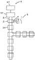
図1は、本発明によるオートメーション・システム1すなわち本発明による制御およびデータ伝送システムの概略図を示している。これは、入出力バス利用部分と関連のセンサおよびアクチュエータが接続されたバス2を有する。標準制御装置4は、このバスをプロセス制御すなわちプロセスリンクの入出力データの処理に使用する。これを行うために、制御装置4は個々のバス利用部分31〜38からデータを受け取り、次にこれらのバス利用部分自体が標準制御装置からデータを受け取る。さらに、標準制御装置は安全関連データの処理を取り扱う。この点で、標準制御装置はプロセスリンクの入力および出力だけでなく、安全関連入力および出力の処理も実行する。本発明によれば、安全関連入力はある種の情報源を示し、その情報源から発せられる情報は本発明によるオートメーション・システムの安全にある程度まで関連する。一例として、このような安全関連入力の1つは、バス利用部分32を介してバス2に接続された旋盤の回転速度センサである。というのは、このマシンは所定の限界以上の速度で回転してはならないからである。本発明の上記の実施形態の安全関連入力のもう1つの例は光バリアの光検出器であり、これは旋盤の動作エリアを監視するために使用する。この場合も、標準制御装置はバスを介して安全関連入力にある情報にアクセスすることができる。たとえば論理リンクの形で安全関連データを処理した後、制御装置4はこの安全関連論理リンク・データを安全関連出力に送る。一例として、最高回転速度を超えており、したがってシステムが制御不能に陥る危険性があるときに、標準制御装置はこのバスを介して前記旋盤用のスイッチオフ・コマンドを関連のバス利用部分32に送ることができる。この場合も、標準制御装置内の安全関連制御装置はこのバスを介して安全関連出力とやりとりする。
【0031】
本発明によるオートメーション・システムは2つの安全分析器5、5’も有し、そのそれぞれはインタフェースによりリアルタイムでバス・システムを介してデータ・フローを監視する。安全分析器は、バス・データストリーム内の安全関連データの論理リンクおよび/または処理用に設定されている。これは、安全分析器がこのバスを介して移送される安全関連データにアクセスできるので、標準制御装置の安全関連論理リンクを取り扱うことができることを意味する。
【0032】
このために、安全分析器5、5’のそれぞれは自由にプログラム可能な論理装置を有し、そこで監視データ、特に監視安全関連データが処理される。一例として、安全分析器5、5’は、標準制御システムの安全関連論理リンクをモデル化して、出力データとしてバスを介して送られるそれぞれの論理リンク・データをチェックすることができる。この場合、安全関連論理リンクは個々のバス利用部分32に関連する。この場合の安全分析器5は、このバス利用部分に関連する安全関連入力および出力に関する責任を負う。図1に示す本発明の実施形態では、安全分析器5、5’はオートメーション・システム内の論理的なバス利用部分ではない。しかし、安全分析器5は安全関連出力6を有し、それを介して安全分析器に関連するバス利用部分32をオフに切り替えることができる。これは接触器7の回路により行われるが、その接触器はバス利用部分と、接続されたアセンブリおよびマシンを供給電圧から切断する。このようにして、安全分析器5は、チェックまたは比較に応答して安全関連機能、この場合は供給電圧のスイッチオフを実行する。たとえば、標準制御装置からの安全関連論理リンク・データ内で障害が識別された場合、標準制御装置によってもたらされる安全関連制御装置はもはや正しく動作していないので、安全分析器は上記の出力を介して関連のバス利用部分をオフに切り替えることができる。同様に、安全関連制御装置が必要なデータをそのバス利用部分に送らず、その結果、システムが未定義状態に変わる危険性がある場合、バス利用部分はオフに切り替えられる。
【0033】
上記の実施形態では、3つのバス利用部分33、34、35を備えたローカル・バス・スパー8がバス・カプラ9を介して配置されている。これらのバス利用部分は、安全分析器5に関連するバス利用部分32の機能性および動作に依存している。したがって、バス利用部分32がオフに切り替えられると、ローカル・バス・スパー8上のバス利用部分も供給電圧から切断することが必要になる。このインタロック論理は安全分析器5に記憶される。したがって、図1に概略で示すように、合計4つのバス利用部分は、それぞれの従属アセンブリおよびマシンとともに、4重接触器7によりオフに切り替えなければならない。
【0034】
第1の安全分析器5のように、安全分析器5’はバスを介して移送されるデータの監視用に設定される。しかし、第1の安全分析器5とは対照的に、この安全分析器は、それによって安全関連機能を実行可能にする入力を備えていない。これに代わって安全関連入力10を有し、それを介して安全分析器がオートメーション・システム内の安全関連装置11に接続され、安全関連データを検出する。この場合、この装置11は、光バリアの一部として溶接ロボットの動作エリアを監視する光検出器を有する。このセンサは、バス利用部分によりオートメーション・バスに接続されていないが、安全分析器5’に直接接続されている。安全分析器5’の安全関連入力10を介して検出された安全関連データに応答して、この場合の安全分析器も安全関連機能を実行する。誰かがロボットの動作エリアに入ったことを光検出器11が検出した場合、安全分析器5’は対応するバス利用部分38とそれに関連するアセンブリおよびロボットを自動的にオフに切り替える。これを行うために、安全分析器5’は、バスに伝送される入力および出力データを操作するための装置を有する。この場合、データストリーム内の少なくとも1つのデータ項目を上書きまたは削除するか、少なくとも1つのデータ項目をバス・データストリーム内に挿入するか、あるいはその両方を実行することができる。このような手順は図6aおよび図6bに示されている。これらの図は、標準制御装置4用の入力および出力データを安全分析器5’によって修正する場合を示している。いずれの場合も、情報ユニット12が安全分析器内のメモリに読み込まれ、次に安全分析器内のもう1つのメモリから取り出された情報ユニットがデータストリーム内の対応するポイントに書き込まれる。バス利用部分とそれに接続されたアセンブリならびにロボットは、標準制御装置の入力データの操作と出力データの操作の両方によりオフに切り替えることができる。たとえば、所定の限界を超えた動作パラメータがあることが標準制御装置4に知らされるように入力データストリームが修正された場合、標準制御装置は、その特定のバス利用部分38に伝送された安全関連論理リンク・データ項目によりバスを介してこのバス利用部分と溶接ロボットをオフに切り替える。同じように、安全分析器は、適切な出力データ項目を上書きすることにより、標準制御装置による使用許可を取り消すことができる。
【0035】
図6bは、安全分析器がバス上の出力データストリームを修正する状況を示している。この状況では、安全分析器は、バス利用部分がその出力と溶接ロボットもオフに切り替えるようにバス利用部分38に送られたデータを操作する。
【0036】
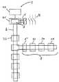
図2は、本発明のもう1つの実施形態を示している。この場合、バスはマスタ/スレーブ原理で動作するシステムであり、標準制御装置はマスタとして動作し、個々のバス利用部分はスレーブとして動作する。このバス・システムはインタフェース・アセンブリ41を介してホスト40に接続され、プロセス関連制御システムはホスト内に配置されて動作し、安全関連制御システムはインタフェース・アセンブリ内に配置されて動作する。このシステムは単一の安全分析器5を有し、これはバス・データストリームを監視するためにインタフェース・アセンブリの直後のバスに結合されている。このような対策は、リング構造によってシリアル・バスに接続されたときに安全分析器がバス上の入力データストリーム全体ならびに出力データストリーム全体を監視できることを保証するものである。安全分析器5は、バスを介するデータストリーム全体に関する知識を使用して、上記の実施形態でこの目的のために設けられたメモリ内に完全なプロセス・マップを記憶する。その結果として、安全分析器は、インタフェース・アセンブリ内の安全関連制御システムに関する安全関連論理リンク・データをすべてチェックすることができ、必要であれば、すなわち障害が発生したときに、出力6を駆動して安全を基礎として接触器7によりシステム全体をオフに切り替え、システム全体の供給電圧がオフに切り替わるようにすることもできる。
【0037】
図3の本発明によるオートメーション・システムは、図2に示す実施形態の修正形態を示している。この場合、安全分析器5はインタフェース・アセンブリ41に統合されている。標準制御装置の安全関連制御および安全分析器内の安全関連データ処理は、インタフェース・アセンブリ内の別々の独立した論理モジュールで実行される。さらに、第2の安全分析器5”はローカル・バス・スパー8の先頭に配置されている。その結果、この配置は安全分析器5”がローカル・バス・スパー8上のバス利用部分33、34、35に関するすべての入力データおよび出力データを監視できることに依存し、したがって、ローカル・バス・スパー内のプロセス・シーケンスに関する完全なプロセス・マップを適用できることに依存する。したがって、長距離バス・セクション内の安全分析器5のように、安全分析器5”はインタフェース・アセンブリ内のローカル・バス・セクション用の安全関連制御システムに関するすべての安全関連論理リンク・データをチェックすることができ、必要であれば、前述のように、データ操作により必要な安全関連機能を開始することができる。このため、ローカル・バス・スパー8は標準制御装置の安全関連制御だけでなく安全分析器5および安全分析器5”にも保護されるので、バス・スパー8に適用可能な安全関連入力および出力に課せられた非常に厳しい安全要件を満たすことができる。
【0038】
図4は、本発明の他の実施形態を示している。本発明によるオートメーション・システムは2つの安全分析器5および5’を有し、その安全関連出力6および6’は互いに結合されている。両方の出力は、システム全体用の供給電圧をオフに切り替えるために複数接触器装置7を制御する。このシステムは、シリアル・バス2を介して標準制御装置4によって制御される。安全分析器5はシステム内に配置されているので、バス上のすべての入力および出力データを監視することができるが、制御装置4と安全分析器5の間に配置された第1のバス利用部分31用の入力データは除く。安全分析器5’はバス上のすべての入力データを監視することができるが、最後のバス利用部分用の出力データを除く、いずれの出力データも安全分析器5’にとってアクセス不能である。したがって、バス・データ・フロー内の関連データをコピーすることにより、第1の安全分析器5はそれがアクセス可能な出力データを入力データにコピーすることができ、したがって、保護すべき安全関連バス利用部分32用のプロセス・マップを適用するために、実際には安全分析器5’にとってアクセス不能な出力データを安全分析器5’にとっても使用可能なものにすることができる。両方の安全分析器は同じ入力情報を受け取るので、保護すべきバス利用部分32の安全関連入力および出力を監視することができる。これは、本発明によるオートメーション・システム内の安全技術に分散冗長性をもたらすことになる。この例では、安全分析器5’は安全関連入力10も有し、この入力に非常用スイッチ13が接続されている。非常用スイッチ13を閉じると、安全分析器5’は、システム全体をオフに切り替えるために、安全分析器内の関連の安全関連機能、すなわち、接触器7の開放で応答する。
【0039】
また、本発明によれば、データ伝送にマスタを必要とせずに、マスタ/スレーブ原理で動作するオートメーション・システム内の2つのスレーブ間にデータ・リンクを設けるために、入力データを出力データにまたその逆にコピーするための上記の方法を使用する。この場合、たとえば、1つのバス利用部分に関連する安全分析器は、そのバス利用部分に関して伝送すべきデータ項目を入力データストリームに挿入し、その結果、マスタを必要とせずにそれを下流のバス利用部分にとって使用可能なものにすることができる。このため、必要であれば、下流の他のバス利用部分すべてに対して単純なやり方で情報をマルチキャストまたは同報することができる。
【0040】
図示していない本発明の一実施形態では、安全分析器が関連の安全ベースのバス利用部分に統合される。この場合、安全ベースの論理リンクはバス利用部分内の論理ユニットに設けられるので、バス利用部分にインストールされた知能を安全ベースの論理リンクに使用することができる。このバス利用部分はバス・インタフェースを有するので、これにより安全分析器に関する追加のハードウェアの複雑さが大幅に低減される。
【0041】
少なくとも一部の場合には、本発明による上記のオートメーション・システム内のデータ伝送にセキュリティ・プロトコルを使用して、このバスを介して安全関連データが伝送される。このセキュリティ・プロトコルは、要件に応じて、安全データ項目に加え、否定安全データ項目とアドレスおよび/またはデータ保護情報をCRCの形で含むことができる。これにより、データ伝送中にエラーを容易に識別できるようになる。このため、本発明によるオートメーション・システムで使用する安全分析器は、それがセキュリティ・プロトコルを読み取り、それを適切に評価できるようにセットアップされる。
【0042】
セキュリティ・プロトコルで伝送される安全バス利用部分のアドレスにより、安全分析器は、プログラミングを適合させ、それに関連する利用部分のデータ・セットを識別し、たとえば安全上の理由からコンポーネントをオフに切り替えた結果としてバス・レイアウトを変更したときにバス・レイアウトの変更を考慮に入れることができる。さらに、セキュリティ・プロトコルにアドレスを含めることにより、分散ユニット内のバス障害または故障による記憶エラーを検出することができる。
【0043】
本発明によるオートメーション・システムで使用するための安全分析器の特定の一実施形態を図5に示す。図示の安全分析器5は、光検出器11からの安全ベースの情報を検出するための4つの安全ベースの入力10だけでなく、接触器により4つのオートメーション・バス・コンポーネントから供給電圧を切断するための4つの安全ベースの出力6も有する。この場合、安全分析器内で論理リンクが生成されたことに応答して、標準制御システム内の安全ベースの論理リンクとの比較に応答して、および/または入力10を介する安全関連入力情報に応答して、様々な安全ベースの出力6が駆動される。この場合、インタロック論理が安全分析器内に記憶され、特定の障害またはエラーが発生したときにどの安全ベースの機能を開始するか、すなわち、その障害またはエラーが発生したときにどのコンポーネントを供給電圧から切断しなければならないかを左右する。
【0044】
安全分析器が、安全関連データの処理に加え、プロセス・データ処理も実行することは、本発明の範囲内である。
【0045】
さらに、本発明の原理は例示的な実施形態に記載されたオートメーション・バス・システムに限定されず、実際にはバスを有するすべてのオートメーション・システムに適用可能であると述べるべきである。
【図面の簡単な説明】
【図1】 長距離バス・システム内に2つの安全分析器を備えた、本発明によるオートメーション・システムの第1の実施形態の概略図である。
【図2】 1つの安全分析器がインタフェース・アセンブリの直後に配置された、本発明の他の実施形態の概略図である。
【図3】 1つの安全分析器がインタフェース・アセンブリ内に統合され、第2の安全分析器がバス・スパーの先頭にある、本発明によるオートメーション・システムを概略図の形で示す図である。
【図4】 その出力が相互に接続された2つの安全分析器を備えた、本発明によるオートメーション・システムを示す図である。
【図5】 様々な入力および出力を備えた安全分析器の概略ブロック図である。
【図6a】 安全分析器によるバス・データストリームのデータ操作の概略図である。
【図6b】 安全分析器によるバス・データストリームのデータ操作の概略図である。[0001]
The invention relates to a safety-related automation bus system as claimed in the characterizing part of claim 1 and to a method for operating such a system.
[0002]
Control and data transmission systems are gaining a superior position as well as industrial production because they enable a high level of automation. In general, such automation systems have sections or components that may be subject to stricter requirements regarding at least safety. For example, it may be necessary to ensure that a given machine is operating within predetermined operating parameters, or to prevent the machine from operating even when someone is within its operating area. In such situations, for example, the lathe must not exceed a predetermined rotational speed, or when operating the robot no one is within the robot's action radius. In addition, when operating an automation system, it is necessary to ensure that if one component in the system fails, the system will not change to an undefined state, and therefore an unpredictable state.
[0003]
One approach to this problem by the prior art is to use multiple channels specifically for safety-related components in the system, i.e. to design such components to be redundant. . For example, a safety bus component, i.e. a bus utilization part associated with a safety-related machine, for example, can be duplicated in an automation bus system. At the same time, the central control and the bus may have multiple channels or even a specific safety control system, but that safety control system is separate from the process control system, and depending on the situation, Redundant design to control safety related components. The safety control system essentially performs a logical link for safety-related input information and then transmits safety-related logical link data to an output component, for example, via an automation bus. The output component itself processes the received safety measure and outputs it to the peripheral device if the test result is positive. In addition, such a component switches its output to a safe state if it finds a fault or does not receive valid data within a predetermined period of time.
[0004]
However, the use of two control systems, the process control system and the safety control system described above, in this system has several disadvantages. In particular, the increasingly stringent requirements regarding the reaction time of automation systems means that such systems often have to be subdivided between safety islands. In addition, especially in multi-channel control systems, synchronization problems arise that can lead to failure or even destruction of machine parts, even though the system is essentially intact. Furthermore, multi-channel designs result in increased system and maintenance costs due to increased hardware complexity.
[0005]
In DE 198 15 150 Al, one device is connected only when it is connected to the bus and continuously monitors the symbols transmitted through the bus system and identifies the coding transmitted through the bus system without error. A system is disclosed that includes an evaluation unit for starting up. For this purpose, the input data sent to the master by the bus utilization part is evaluated, and the device is switched on or off in response to the evaluation.
[0006]
Such an approach is not as expensive as the first described system, but is very inflexible with respect to system upgrades or alignment of the system with other bus components. Furthermore, since the evaluation unit is only responsible for the start of safety-based functions, it is absolutely essential that the evaluation unit is of a redundant design in order to comply with strict safety requirements.
[0007]
Accordingly, it is an object of the present invention to provide a safety-related automation bus system that requires as little hardware redundancy as possible and can be flexibly adapted to each requirement.
[0008]
The present invention solves this problem by an automation bus system having the features of claim 1 and a method claimed in claim 14 for operating such a control and data processing system. Developments of the invention are specified in the dependent claims.
[0009]
According to the present invention, this automation system includes a bus system, a sensor and actuator bus utilization part connected thereto, a process control function by processing input / output data of a process link, and safety by processing safety-related data. And associated control functions, i.e., standard controllers that perform safety-related input and output control. This also includes what is called a safety analyzer, which is connected to the bus by an appropriate interface and monitors the data flow through the bus but is set up to perform safety-related functions. This is relevant, for example, for determining contactor actuation or quality data to turn off the supply voltage to system components. Such quality data may include general system parameters, for example, data regarding the occurrence of failures in system components or bus transmission errors. This automation system is characterized by the fact that a standard controller drives at least one safety-related output via a bus, but can itself have such a safety-related output. According to the present invention, safety-related output means a safety-based sequence as a function of safety information, for example, a sink of safety information that initiates machine switch-off due to machine deceleration or power supply interruption. The safety analyzer in the automation system according to the invention is designed for checking and / or processing safety-related data in the bus data stream, in particular safety-related logical link data. In this case, the safety-related logical link data is, for example, data that the safety-related control system sends to the safety-related output after processing the safety-related data.
[0010]
Therefore, it provides a system that can be adapted very flexibly to the respective requirements for automation systems. For example, one safety analyzer can be allocated for each safety bus component, with each safety analyzer having a bus data stream for multiple safety bus components or all safety bus components in the system. While it is possible to process safety-related data within or to check safety-related logical link data, the safety analyzer itself can also be integrated into a safety component such as a safety bus utilization part.
[0011]
The principle of the present invention is based on the fact that in the inventor's experience, the electronic equipment used in current automation systems itself rarely fails. The integration of current digital safety technology into automation technology in the form of a prior art safety control system or safety bus system often results in the disadvantage of reduced system availability. Thus, in order to reduce downtime, in addition to the safety components described above, an availability structure is also used, but this structure itself increases the complexity of the hardware, which increases the cost considerably. .
[0012]
Thus, the present invention is based on the reliability of current automation systems and integrates pure emergency electronic equipment or software, which only works when the standard technology is operating improperly. Will be actively involved in the operation. Thus, the standard controller also processes safety related data, i.e. controls safety related inputs and outputs. In particular, however, safety-related logical link data generated in the bus data stream is monitored and checked by the safety analyzer. This gives the user the advantage that it is no longer absolutely necessary to maintain a strict separation between circuit technology and standard technology during programming. The automation system according to the invention can be used on any system with a bus, in particular on a bus system using a master / slave bus access method. Regardless of placing the safety analyzer in the long-haul bus section, the safety analyzer can read all IN data on the bus in a serial bus system, eg according to EN 50 254, The amount of OUT data that can be monitored depends on the placement of the safety analyzer in the system. The expression bus data stream in this case means according to the invention all information transmitted over the bus, in particular including data transferred over the bus within a total frame.
[0013]
In order to comply with the relevant safety requirements, the safety analyzer can initiate the required safety-related functions in response to checking and / or processing of safety-related data, particularly logical link data in the bus data stream. . In this case, the safety analyzer is not only responsible for the OUT data, ie the logical link data from the standard controller, but also the IN data, ie the information in the bus data stream sent from the individual I / O bus utilization part to the standard controller. Can also react.
[0014]
In order to identify errors in the safety-related logical link data transported over the bus, the safety analyzer can have a fully programmable logic device, in which monitoring data, in particular monitoring safety-related data, is stored. It is processed. Therefore, by modeling the safety-related logical link of a standard control system, the safety analyzer can check the logical link data of this control system sent as OUT data via the bus. Or, necessary safety-related functions can be performed in response to the comparison. For example, to change the system to a safe state, the safety analyzer may have an output through which an assembly in the automation system, in particular the bus utilization part, can be switched on or off. This switch-off process can be performed by disconnecting from the voltage supply. In order to change all related bus usage parts independent of each other to a safe state, the safety analyzer switches off a bus spar, i.e. a safety island containing multiple bus usage parts related to each other, or The component can be set up to switch off based on the interlock logic stored in the analyzer. However, it is also possible to disconnect the entire system from the voltage supply via the safety-related outputs of the safety analyzer.
[0015]
In addition to monitoring the bus, the safety analyzer can also detect safety-related information via a direct input, which connects the safety analyzer to a safety-related device in the automation bus system. In this case, the device can be connected to the bus, but this is not necessary. As an example, the safety-related information accessible in this way includes the aforementioned instantaneous turning speed of the lathe, and the analyzer output switches the machine off when a predetermined limit speed is exceeded.
[0016]
To separate safety-related information and process data in the system, especially in the control system, the bus system can be connected to the host via an interface assembly, and the process-related controls of standard controllers are located in the host. The safety related controls of the standard controller are located in the interface assembly. For example, a safety-related control system can advantageously be in the form of a software function module that performs the necessary logical links for safety-related input / output information.
[0017]
Therefore, the safety-related control system can be realized in the same way as the process control system. When coding safety-related logical links, the programmer is independent of the programming language in use, as is the case with process control systems.
[0018]
The logical links in the safety analyzer have approximately the same scope as the logical links in the host and in the interface assembly and can be generated in the same or different programming languages. The safety analyzer also performs a logical link comparison between the results from the host system and / or interface assembly and its own results, for example, initiating safety-based functions if they are not equal.
[0019]
The acceptance procedure for such a system can be performed much more easily than in the case of systems according to the prior art. The system can be triggered by all safety interlocks without having to actively switch safety techniques. In this case, the required logical links are located in the host system or in the interface assembly. First of all, the black box test can be used to investigate the functionality of this system. Next, in a second step, safety techniques are connected in the form of one or more safety analyzers. If there is only a safety logical link rather than a process data logical link, the white box test can be performed quickly and unambiguously, resulting in a significant reduction in acceptance time. Since the safety management logic algorithm can also be executed on the host system and / or interface assembly, a comparison with that in the analyzer can be performed quickly.
[0020]
If this bus is a serial ring bus, for example a bus according to EN 50254, and the safety analyzer is located in the top-level long-distance bus section of the automation system, each bus in the system referred to here This bus can access all IN data in the system because data is transmitted on the forward and return transmission lines by the utilization part. Thus, the analyzer can form a process map that is limited to the IN and OUT data that it can access.
[0021]
In a bus system with a linear topology, the safety analyzer can generally read all the information at any point in the bus system and thus generate a complete process map.
[0022]
In an advantageous embodiment of the present invention, the safety analyzer is placed immediately after the host or interface assembly in the serial ring bus system, so that a complete process map can be formed. Therefore, the safety analyzer can always check and process safety-based data, especially safety-based logical link data, for correctness. This is because in this case the analyzer has access to all IN and OUT data, ie all input and output data.
[0023]
If the safety analyzer is located within the interface assembly of the serial ring bus system described above, the functions of the safety analyzer can be performed by software components within the interface assembly. The interface assembly in this case advantageously has a safety-related output in order to perform an appropriate safety-based function, for example switching off the supply voltage by means of a contactor.
[0024]
However, in one particularly advantageous embodiment of the invention, such safety-based functions can be performed by direct data manipulation of the bus data stream by the safety analyzer. This operation includes rewriting, adding, inserting or replacing both OUT and IN data in the bus data stream. Thus, if the process map is known, the safety analyzer can affect the operation of the automation system according to the invention in a wide variety of ways, thus ensuring that the system can be kept in a defined state at any time. be able to. In addition, safety analyzers located in long-distance buses convert related data into data that is transported in the relevant bus spar, so that bus analyzers that are generally inaccessible by safety analyzers located in the bus spar. Data manipulation principles can also be used to enable the data stream component. This allows a direct data link between safety analyzers.
[0025]
Data manipulation by the safety analyzer is based on the master / slave principle, in order to transmit data between at least two slaves, especially between individual bus utilizations, via a point-to-point link via at least one safety analyzer. It can also be used in a working bus system and the safety analyzer copies the data in the bus data stream. Depending on the location of the two slaves in the bus system, the master may not be included in this data link in some situations, and data transfer takes place completely independent of the bus master. Apart from this, such a data link between two slaves is possible even when the bus master is performing a copy function. When the safety analyzer is operating as an agent as described above, the bus master is not included in the data transfer at least in the given situation, but for the second form of point-to-point link between two slaves. A bus master is absolutely essential.
[0026]
Furthermore, data exchange between at least two slaves over a point-to-point link, for example between individual bus utilization parts, is made possible by including a master or control system in the transmission, in which case the master or control system is Copy the data in the bus data stream.
[0027]
To improve data security, security-related data can also be transmitted over the bus using a security protocol. For example, a security protocol can include not only safety data items, but also negative safety data items, sequence numbers, addresses, and / or data protection information (CRC).
[0028]
The flexibility of the system is particularly evident in another advantageous embodiment of the invention, in which the automation system according to the invention has a plurality of safety analyzers and runs on one safety analyzer The safety management logic link to be performed is performed in a redundant manner with at least one other safety analyzer, and the same safety function is at least partially performed and initiated by both safety analyzers. In this case, the associated safety analyzer can also perform other safety-related logic links in addition to the redundant logic links, i.e. those that run on both analyzers.
[0029]
The invention is described in the following text by describing several embodiments on the basis of the attached drawings.
[0030]
FIG. 1 shows a schematic diagram of an automation system 1 according to the invention, ie a control and data transmission system according to the invention. It has a
[0031]
The automation system according to the invention also has two
[0032]
For this purpose, each of the
[0033]
In the above embodiment, the
[0034]
Like the
[0035]
FIG. 6b shows the situation where the safety analyzer modifies the output data stream on the bus. In this situation, the safety analyzer manipulates the data sent to the
[0036]
FIG. 2 illustrates another embodiment of the present invention. In this case, the bus is a system that operates on the master / slave principle, the standard control device operates as a master, and the individual bus using portions operate as slaves. The bus system is connected to the
[0037]
The automation system according to the invention of FIG. 3 shows a modification of the embodiment shown in FIG. In this case, the
[0038]
FIG. 4 shows another embodiment of the present invention. The automation system according to the invention has two
[0039]
Also, according to the present invention, input data can be transferred to output data in order to provide a data link between two slaves in an automation system operating on the master / slave principle without requiring a master for data transmission. Conversely, the above method for copying is used. In this case, for example, the safety analyzer associated with one bus utilization part inserts the data item to be transmitted for that bus utilization part into the input data stream, so that it is not required by the master and is sent to the downstream bus. It can be made usable for the utilization part. Thus, if necessary, information can be multicast or broadcast in a simple manner to all other bus utilization parts downstream.
[0040]
In one embodiment of the invention not shown, a safety analyzer is integrated into the relevant safety-based bus utilization part. In this case, since the safety-based logical link is provided in the logical unit in the bus utilization part, the intelligence installed in the bus utilization part can be used for the safety-based logical link. Since this bus utilization part has a bus interface, this greatly reduces the additional hardware complexity associated with the safety analyzer.
[0041]
In at least some cases, safety related data is transmitted over this bus using a security protocol for data transmission within the above automation system according to the present invention. This security protocol can include negative safety data items and address and / or data protection information in the form of CRC, in addition to safety data items, depending on requirements. This makes it easy to identify errors during data transmission. For this reason, the safety analyzer used in the automation system according to the invention is set up so that it can read the security protocol and evaluate it appropriately.
[0042]
With the address of the safety bus utilization part transmitted in the security protocol, the safety analyzer adapted the programming and identified the relevant utilization part data set, eg switching off the component for safety reasons. As a result, changes to the bus layout can be taken into account when the bus layout is changed. Further, by including an address in the security protocol, a storage error due to a bus failure or failure in the distributed unit can be detected.
[0043]
One particular embodiment of a safety analyzer for use in an automation system according to the present invention is shown in FIG. The illustrated
[0044]
It is within the scope of the present invention for the safety analyzer to perform process data processing in addition to processing safety related data.
[0045]
Furthermore, it should be stated that the principles of the present invention are not limited to the automation bus system described in the exemplary embodiment, but are actually applicable to any automation system having a bus.
[Brief description of the drawings]
FIG. 1 is a schematic diagram of a first embodiment of an automation system according to the invention with two safety analyzers in a long distance bus system.
FIG. 2 is a schematic diagram of another embodiment of the present invention with one safety analyzer positioned immediately after the interface assembly.
FIG. 3 shows, in schematic form, an automation system according to the invention, in which one safety analyzer is integrated in the interface assembly and a second safety analyzer is at the top of the bus spar.
FIG. 4 shows an automation system according to the present invention with two safety analyzers whose outputs are connected to each other.
FIG. 5 is a schematic block diagram of a safety analyzer with various inputs and outputs.
FIG. 6a is a schematic diagram of data manipulation of a bus data stream by a safety analyzer.
FIG. 6b is a schematic diagram of data manipulation of the bus data stream by the safety analyzer.
Claims (31)
Translated fromJapaneseそれに接続された入出力バス利用部分(31〜38)および標準制御装置(4;40、41)と、
バス・システムを介してデータ・フローを監視し、少なくとも1つの安全関連機能を実行するよう設計された少なくとも1つの安全分析器(5、5’、5”)を含み、
安全分析器がバス・データストリーム内の安全関連データをチェックして処理するためにセットアップされるか、バス(2)上で伝送されるデータストリームを操作するための装置を有するか、あるいはその両方であることを特徴とする、オートメーション・システム(1)。At least the bus system (2),
An input / output bus utilization part (31-38) and a standard control unit (4; 40, 41) connected to it;
Including at least one safety analyzer (5, 5 ', 5 ") designed to monitor data flow through the bus system and perform at least one safety-related function;
The safety analyzer is set up to check and process safety related data in the bus data stream, or has a device for manipulating the data stream transmitted on the bus (2), or both An automation system (1) characterized by
標準制御装置(4;40、41)がプロセスリンクの入出力データの処理によるプロセス制御と、安全関連データの処理による安全関連制御とを実行し、さらに、安全関連データの処理が少なくとも1つの安全分析器(5、5’、5”)において実行され、安全関連データ、特にバス・データストリーム内の安全関連論理リンク・データが安全分析器で処理されることを特徴とする方法。A method for operating an automation system, in particular an automation system (1) according to any one of claims 1 to 14, comprising:
The standard control device (4; 40, 41) executes process control by processing input / output data of the process link and safety-related control by processing safety-related data, and at least one safety-related data is processed. A method characterized in that it is executed in an analyzer (5, 5 ', 5 ") and safety-related data, in particular safety-related logical link data in a bus data stream, is processed in a safety analyzer.
Applications Claiming Priority (3)
| Application Number | Priority Date | Filing Date | Title |
|---|---|---|---|
| DE19927635ADE19927635B4 (en) | 1999-06-17 | 1999-06-17 | Security related automation bus system |
| DE19927635.8 | 1999-06-17 | ||
| PCT/DE2000/001901WO2000079352A2 (en) | 1999-06-17 | 2000-06-16 | Security-related bus automation system |
Related Child Applications (1)
| Application Number | Title | Priority Date | Filing Date |
|---|---|---|---|
| JP2006290303ADivisionJP2007060710A (en) | 1999-06-17 | 2006-10-25 | Security-related automation bus system |
Publications (2)
| Publication Number | Publication Date |
|---|---|
| JP2003502981A JP2003502981A (en) | 2003-01-21 |
| JP4317341B2true JP4317341B2 (en) | 2009-08-19 |
Family
ID=7911544
Family Applications (2)
| Application Number | Title | Priority Date | Filing Date |
|---|---|---|---|
| JP2001505254AExpired - LifetimeJP4317341B2 (en) | 1999-06-17 | 2000-06-16 | Safety-related automation bus system |
| JP2006290303APendingJP2007060710A (en) | 1999-06-17 | 2006-10-25 | Security-related automation bus system |
Family Applications After (1)
| Application Number | Title | Priority Date | Filing Date |
|---|---|---|---|
| JP2006290303APendingJP2007060710A (en) | 1999-06-17 | 2006-10-25 | Security-related automation bus system |
Country Status (7)
| Country | Link |
|---|---|
| US (1) | US6957115B1 (en) |
| EP (1) | EP1192511B1 (en) |
| JP (2) | JP4317341B2 (en) |
| AT (1) | ATE268016T1 (en) |
| DE (2) | DE19927635B4 (en) |
| ES (1) | ES2216929T3 (en) |
| WO (1) | WO2000079352A2 (en) |
Cited By (1)
| Publication number | Priority date | Publication date | Assignee | Title |
|---|---|---|---|---|
| JP2007060710A (en)* | 1999-06-17 | 2007-03-08 | Phoenix Contact Gmbh & Co | Security-related automation bus system |
Families Citing this family (46)
| Publication number | Priority date | Publication date | Assignee | Title |
|---|---|---|---|---|
| DE19928517C2 (en)† | 1999-06-22 | 2001-09-06 | Pilz Gmbh & Co | Control system for controlling safety-critical processes |
| DE10201212A1 (en)* | 2002-03-26 | 2003-07-24 | Leuze Electronic Gmbh & Co | Safety switch arrangement has output stages controlled by code in safety monitor, which sends code to master in response to a master request call; slaves send reply dependent on code |
| EP1327922B1 (en)* | 2002-01-14 | 2004-04-07 | Leuze electronic GmbH + Co KG | Safety switch arrangement |
| AT500705B1 (en)* | 2002-02-08 | 2007-07-15 | Thyssen Fahrtreppen Gmbh | TRAILER OR RIDE |
| DE10309098A1 (en)* | 2003-03-03 | 2004-09-16 | Leuze Electronic Gmbh + Co Kg | Control for controlling safety-relevant processes |
| GB0312414D0 (en)* | 2003-05-30 | 2003-07-02 | Fortress Interlocks Ltd | Security or safety bus system |
| DE10330916A1 (en)† | 2003-07-04 | 2005-02-03 | Pilz Gmbh & Co. Kg | Device and method for the automated control of an operating procedure in a technical installation |
| US7280048B2 (en) | 2003-08-07 | 2007-10-09 | Rosemount Inc. | Process control loop current verification |
| US7018800B2 (en) | 2003-08-07 | 2006-03-28 | Rosemount Inc. | Process device with quiescent current diagnostics |
| DE10337699B4 (en)* | 2003-08-16 | 2006-01-12 | Phoenix Contact Gmbh & Co. Kg | Method and device for transmitting data over a bus network using the broadcast principle |
| US8180466B2 (en)* | 2003-11-21 | 2012-05-15 | Rosemount Inc. | Process device with supervisory overlayer |
| US7464721B2 (en) | 2004-06-14 | 2008-12-16 | Rosemount Inc. | Process equipment validation |
| DE102004035442B4 (en)* | 2004-07-22 | 2006-06-01 | Phoenix Contact Gmbh & Co. Kg | Method and device for safe switching of an automation bus system |
| DE102004058940B4 (en)* | 2004-12-07 | 2009-06-25 | Sick Ag | Detector unit and method for data transmission |
| DE102005007477B4 (en)* | 2005-02-17 | 2015-06-11 | Bosch Rexroth Aktiengesellschaft | Programmable control for machine and / or plant automation with standard control and safety functions and communication with a safety I / O and method for operating the programmable controller |
| DE102005009707A1 (en)* | 2005-03-03 | 2006-09-07 | Dr. Johannes Heidenhain Gmbh | Modular numerical control unit |
| DE102006004339A1 (en)* | 2006-01-30 | 2007-08-02 | Robert Bosch Gmbh | Redundant communication network |
| DE102007016917B4 (en)* | 2007-04-05 | 2009-12-17 | Phoenix Contact Gmbh & Co. Kg | Method and system for the secure transmission of cyclic process data to be transmitted |
| US7788432B2 (en)* | 2007-10-26 | 2010-08-31 | International Business Machines Corporation | System for performing a serial communication between a central control block and satellite components |
| DE202008009211U1 (en)* | 2008-07-09 | 2008-09-25 | Robert Bosch Gmbh | Device for detecting interruptions in a ring bus |
| DE102009019087A1 (en)* | 2009-04-20 | 2010-11-11 | Pilz Gmbh & Co. Kg | Safety control and method for controlling an automated plant |
| DE102009022389A1 (en)* | 2009-05-22 | 2010-12-02 | Phoenix Contact Gmbh & Co. Kg | Control system for controlling a process |
| DE102009042368B4 (en)* | 2009-09-23 | 2023-08-17 | Phoenix Contact Gmbh & Co. Kg | Control system for controlling safety-critical processes |
| EP2317410B1 (en) | 2009-10-23 | 2012-01-04 | Sick Ag | Safety control |
| AT509310B1 (en)* | 2009-12-16 | 2015-10-15 | Bachmann Gmbh | METHOD FOR OPERATING A MEMORY PROGRAMMABLE CONTROL (PLC) WITH DECENTRALIZED, AUTONOMOUS EXECUTION CONTROL |
| DE102010022931B4 (en)* | 2010-06-07 | 2023-04-20 | Kuka Roboter Gmbh | robot controller |
| DE102010038484A1 (en) | 2010-07-27 | 2012-02-02 | Fraunhofer-Gesellschaft zur Förderung der angewandten Forschung e.V. | Plant controlling method, involves transmitting error signal to output modules independent of fixed transmission sequence, and transferring control signal to plant in safe state based on error signal |
| DE102011007049A1 (en)* | 2011-04-08 | 2012-10-11 | Siemens Ag Österreich | Rapid emergency shutdown of distributed equipment and associated apparatus |
| JP5632804B2 (en)* | 2011-08-08 | 2014-11-26 | オークマ株式会社 | Control device with bus diagnostic function |
| US9020768B2 (en) | 2011-08-16 | 2015-04-28 | Rosemount Inc. | Two-wire process control loop current diagnostics |
| WO2014101925A1 (en)* | 2012-12-24 | 2014-07-03 | Festo Ag & Co. Kg | Field unit and a method for operating an automation system |
| DE102013009644A1 (en)* | 2013-06-08 | 2014-12-11 | Robert Bosch Gmbh | Safety device and safety procedure for performing safety functions for a machine or plant |
| DE102013217063A1 (en)* | 2013-08-27 | 2015-03-05 | E.G.O. Elektro-Gerätebau GmbH | Appliances Control |
| DE102014100970A1 (en) | 2014-01-28 | 2015-07-30 | Pilz Gmbh & Co. Kg | Method and device for safely switching off an electrical load |
| DE102014001462B4 (en)* | 2014-02-05 | 2021-02-04 | Festo Se & Co. Kg | Field bus module, machine control and method for parameterizing an, in particular safety-related, field bus module |
| DE102014208709A1 (en)* | 2014-05-09 | 2015-11-12 | Smiths Heimann Gmbh | SAFETY DEVICE |
| DE102014017240A1 (en)* | 2014-11-21 | 2016-05-25 | Festo Ag & Co. Kg | Drive system and method for operating a drive system |
| US10367612B2 (en) | 2015-09-30 | 2019-07-30 | Rosemount Inc. | Process variable transmitter with self-learning loop diagnostics |
| DE102015118151A1 (en) | 2015-10-23 | 2017-04-27 | Bernstein Ag | Safety sensor for monitoring the operational safety of a system |
| ES2808156T3 (en) | 2016-07-13 | 2021-02-25 | Siemens Energy Global Gmbh & Co Kg | Procedure for controlling a drive |
| DE102017208831A1 (en)* | 2017-05-24 | 2018-11-29 | Wago Verwaltungsgesellschaft Mbh | Processing of process data |
| EP3416337B1 (en) | 2017-06-12 | 2019-09-25 | Smart PLACE AG | Device for automation of a house or building |
| CN110290597B (en)* | 2018-07-04 | 2022-08-30 | 湖北坚丰科技股份有限公司 | EPR data updating and transmitting method and device for automatic lathe |
| DE102019207809A1 (en)* | 2019-05-28 | 2020-12-03 | Siemens Mobility GmbH | Control system and method for operating a control system |
| US11218360B2 (en) | 2019-12-09 | 2022-01-04 | Quest Automated Services, LLC | Automation system with edge computing |
| CN113282070B (en)* | 2021-04-08 | 2025-07-29 | 深圳元戎启行科技有限公司 | Bus port fault judging method and system |
Family Cites Families (23)
| Publication number | Priority date | Publication date | Assignee | Title |
|---|---|---|---|---|
| US4680753A (en)* | 1985-04-03 | 1987-07-14 | Texas Instruments Incorporated | System and method for controlling network bus communications for input-output interlocking information among distributed programmable controllers |
| GB2200476B (en)* | 1987-01-29 | 1991-02-06 | British Gas Plc | Monitor system |
| US5161110A (en)* | 1990-02-27 | 1992-11-03 | Atlantic Richfield Company | Hierarchical process control system and method |
| DE4240071A1 (en)* | 1992-11-28 | 1994-06-01 | Square D Deutschland | Circuit arrangement for electrical safety monitoring of switching devices |
| DE4312305C5 (en)* | 1993-04-15 | 2004-07-15 | Abb Patent Gmbh | Safety-related programmable logic controller |
| DE19509558A1 (en)* | 1995-03-16 | 1996-09-19 | Abb Patent Gmbh | Process for fault-tolerant communication under high real-time conditions |
| DE19510470A1 (en)* | 1995-03-26 | 1996-10-17 | Klaschka Ind Elektronik | Digital controller with peripheral devices |
| DE19540069A1 (en)* | 1995-10-27 | 1997-04-30 | Elan Schaltelemente Gmbh | Arrangement for the detection and / or processing of signals of electrical components that fulfill safety-related purposes or requirements for devices or systems |
| DE19643092C2 (en)* | 1996-10-18 | 1998-07-30 | Elan Schaltelemente Gmbh | Field data bus system |
| DE19815147B4 (en)* | 1997-04-21 | 2005-03-17 | Leuze Electronic Gmbh & Co Kg | sensor arrangement |
| DE19815150B4 (en)* | 1997-04-21 | 2005-03-10 | Leuze Electronic Gmbh & Co Kg | sensor arrangement |
| DE19718284C2 (en)* | 1997-05-01 | 2001-09-27 | Kuka Roboter Gmbh | Method and device for monitoring a system with several functional units |
| DE19814102C2 (en)* | 1998-03-30 | 1999-05-12 | Siemens Ag | Data transmission method |
| US6325198B1 (en)* | 1998-06-26 | 2001-12-04 | Eveready Battery Company, Inc. | High speed manufacturing system |
| DE19834331A1 (en)* | 1998-07-30 | 2000-02-10 | Bosch Gmbh Robert | Safety device for a programmable logic controller |
| DE19840562B4 (en)* | 1998-09-07 | 2007-06-28 | Phoenix Contact Gmbh & Co. Kg | Security-related control and data transmission system |
| DE19857683B4 (en)* | 1998-12-14 | 2007-06-28 | Wratil, Peter, Dr. | Method for monitoring the safety of control devices |
| DE19860358B4 (en)* | 1998-12-24 | 2008-05-08 | Wratil, Peter, Dr. | Method for error suppression in output units in control devices |
| DE19904893B4 (en)* | 1999-02-06 | 2007-10-18 | Wratil, Peter, Dr. | Method for error suppression in control devices by an intelligent monitoring unit |
| DE19905841A1 (en)* | 1999-02-12 | 2000-08-24 | Kuka Roboter Gmbh | Device for processing security-relevant data |
| DE19908230A1 (en)* | 1999-02-25 | 2000-08-31 | Heidelberger Druckmasch Ag | Device for monitoring safety-related processes on machines |
| DE19913279B4 (en)* | 1999-03-24 | 2006-07-27 | Wratil, Peter, Dr. | Control device with monitoring unit for error detection and error suppression |
| DE19927635B4 (en)* | 1999-06-17 | 2009-10-15 | Phoenix Contact Gmbh & Co. Kg | Security related automation bus system |
- 1999
- 1999-06-17DEDE19927635Apatent/DE19927635B4/ennot_activeExpired - Lifetime
- 2000
- 2000-06-16WOPCT/DE2000/001901patent/WO2000079352A2/enactiveIP Right Grant
- 2000-06-16DEDE50006611Tpatent/DE50006611D1/ennot_activeExpired - Lifetime
- 2000-06-16ESES00951209Tpatent/ES2216929T3/ennot_activeExpired - Lifetime
- 2000-06-16ATAT00951209Tpatent/ATE268016T1/enactive
- 2000-06-16JPJP2001505254Apatent/JP4317341B2/ennot_activeExpired - Lifetime
- 2000-06-16USUS10/018,721patent/US6957115B1/ennot_activeExpired - Lifetime
- 2000-06-16EPEP00951209Apatent/EP1192511B1/ennot_activeExpired - Lifetime
- 2006
- 2006-10-25JPJP2006290303Apatent/JP2007060710A/enactivePending
Cited By (1)
| Publication number | Priority date | Publication date | Assignee | Title |
|---|---|---|---|---|
| JP2007060710A (en)* | 1999-06-17 | 2007-03-08 | Phoenix Contact Gmbh & Co | Security-related automation bus system |
Also Published As
| Publication number | Publication date |
|---|---|
| EP1192511A2 (en) | 2002-04-03 |
| JP2007060710A (en) | 2007-03-08 |
| DE50006611D1 (en) | 2004-07-01 |
| EP1192511B1 (en) | 2004-05-26 |
| WO2000079352A2 (en) | 2000-12-28 |
| WO2000079352A3 (en) | 2001-05-03 |
| DE19927635A1 (en) | 2001-01-04 |
| ATE268016T1 (en) | 2004-06-15 |
| JP2003502981A (en) | 2003-01-21 |
| US6957115B1 (en) | 2005-10-18 |
| ES2216929T3 (en) | 2004-11-01 |
| DE19927635B4 (en) | 2009-10-15 |
Similar Documents
| Publication | Publication Date | Title |
|---|---|---|
| JP4317341B2 (en) | Safety-related automation bus system | |
| US6853292B1 (en) | Security control system, method for the operation thereof | |
| US8509927B2 (en) | Control system for controlling safety-critical processes | |
| US9934111B2 (en) | Control and data transmission system, process device, and method for redundant process control with decentralized redundancy | |
| CA2424853C (en) | Control system and process for several actuators | |
| US7269465B2 (en) | Control system for controlling safety-critical processes | |
| JP6167532B2 (en) | Control device and operation method of control device | |
| US9665072B2 (en) | Method for determining a safety step and safety manager | |
| US8132042B2 (en) | Method and device for exchanging data on the basis of the OPC communications protocol between redundant process automation components | |
| US20020052717A1 (en) | Method and apparatus for monitoring a plant with several functional units | |
| US20030140270A1 (en) | Redundant control system and control computer and peripheral unit for a control system of this type | |
| CN208673079U (en) | Safety control system of industrial robot and industrial robot | |
| JP2012524354A (en) | Safety controller for controlling an automation system and method for generating a user program | |
| US8090474B2 (en) | Apparatus for controlling at least one machine | |
| US7149925B2 (en) | Peripheral component with high error protection for stored programmable controls | |
| US9128480B2 (en) | Safety controller and method for controlling an automated installation | |
| JPH0259901A (en) | Fault diagnosing system | |
| JP4328352B2 (en) | Diagnostic method and system for external signal input / output unit | |
| US10386832B2 (en) | Redundant control system for an actuator and method for redundant control thereof | |
| US9241043B2 (en) | Method of connecting a hardware module to a fieldbus | |
| JP4788597B2 (en) | Programmable controller redundant system | |
| US10712724B2 (en) | Failsafe automation system | |
| JP4348485B2 (en) | Process control device | |
| KR20000021045A (en) | Method and system for performing dual operating of computer control | |
| Kim et al. | Implementation of Multiloop Control for the Plant Control System in Improved Korean Standard Nuclear Power Plant (KSNP+) |
Legal Events
| Date | Code | Title | Description |
|---|---|---|---|
| A977 | Report on retrieval | Free format text:JAPANESE INTERMEDIATE CODE: A971007 Effective date:20051110 | |
| A131 | Notification of reasons for refusal | Free format text:JAPANESE INTERMEDIATE CODE: A131 Effective date:20051114 | |
| A601 | Written request for extension of time | Free format text:JAPANESE INTERMEDIATE CODE: A601 Effective date:20060214 | |
| A602 | Written permission of extension of time | Free format text:JAPANESE INTERMEDIATE CODE: A602 Effective date:20060221 | |
| A02 | Decision of refusal | Free format text:JAPANESE INTERMEDIATE CODE: A02 Effective date:20060626 | |
| A521 | Request for written amendment filed | Free format text:JAPANESE INTERMEDIATE CODE: A821 Effective date:20061206 | |
| A01 | Written decision to grant a patent or to grant a registration (utility model) | Free format text:JAPANESE INTERMEDIATE CODE: A01 | |
| A61 | First payment of annual fees (during grant procedure) | Free format text:JAPANESE INTERMEDIATE CODE: A61 Effective date:20090522 | |
| R150 | Certificate of patent or registration of utility model | Free format text:JAPANESE INTERMEDIATE CODE: R150 Ref document number:4317341 Country of ref document:JP Free format text:JAPANESE INTERMEDIATE CODE: R150 | |
| FPAY | Renewal fee payment (event date is renewal date of database) | Free format text:PAYMENT UNTIL: 20120529 Year of fee payment:3 | |
| FPAY | Renewal fee payment (event date is renewal date of database) | Free format text:PAYMENT UNTIL: 20130529 Year of fee payment:4 | |
| R250 | Receipt of annual fees | Free format text:JAPANESE INTERMEDIATE CODE: R250 | |
| FPAY | Renewal fee payment (event date is renewal date of database) | Free format text:PAYMENT UNTIL: 20140529 Year of fee payment:5 | |
| R250 | Receipt of annual fees | Free format text:JAPANESE INTERMEDIATE CODE: R250 | |
| R250 | Receipt of annual fees | Free format text:JAPANESE INTERMEDIATE CODE: R250 | |
| R250 | Receipt of annual fees | Free format text:JAPANESE INTERMEDIATE CODE: R250 | |
| R250 | Receipt of annual fees | Free format text:JAPANESE INTERMEDIATE CODE: R250 | |
| R250 | Receipt of annual fees | Free format text:JAPANESE INTERMEDIATE CODE: R250 | |
| R250 | Receipt of annual fees | Free format text:JAPANESE INTERMEDIATE CODE: R250 | |
| R250 | Receipt of annual fees | Free format text:JAPANESE INTERMEDIATE CODE: R250 | |
| R250 | Receipt of annual fees | Free format text:JAPANESE INTERMEDIATE CODE: R250 | |
| EXPY | Cancellation because of completion of term |