JP4317008B2 - MIMO transmission system, transmission apparatus, reception apparatus and method in wireless network - Google Patents
MIMO transmission system, transmission apparatus, reception apparatus and method in wireless networkDownload PDFInfo
- Publication number
- JP4317008B2 JP4317008B2JP2003508001AJP2003508001AJP4317008B2JP 4317008 B2JP4317008 B2JP 4317008B2JP 2003508001 AJP2003508001 AJP 2003508001AJP 2003508001 AJP2003508001 AJP 2003508001AJP 4317008 B2JP4317008 B2JP 4317008B2
- Authority
- JP
- Japan
- Prior art keywords
- information
- sub
- signal
- shared
- encoded
- Prior art date
- Legal status (The legal status is an assumption and is not a legal conclusion. Google has not performed a legal analysis and makes no representation as to the accuracy of the status listed.)
- Expired - Fee Related
Links
- 230000005540biological transmissionEffects0.000titleclaimsabstractdescription60
- 238000000034methodMethods0.000titleclaimsdescription43
- 238000000638solvent extractionMethods0.000claimsdescription7
- 238000004891communicationMethods0.000claimsdescription2
- 230000008054signal transmissionEffects0.000claimsdescription2
- 230000001419dependent effectEffects0.000claims2
- 238000000926separation methodMethods0.000claims1
- 238000005562fadingMethods0.000description16
- 230000000875corresponding effectEffects0.000description12
- 239000011159matrix materialSubstances0.000description11
- 238000013459approachMethods0.000description9
- 238000010586diagramMethods0.000description9
- 238000012545processingMethods0.000description8
- 239000000654additiveSubstances0.000description6
- 230000000996additive effectEffects0.000description6
- 238000012546transferMethods0.000description6
- 238000000605extractionMethods0.000description4
- 238000007476Maximum LikelihoodMethods0.000description3
- 230000008901benefitEffects0.000description3
- 230000000694effectsEffects0.000description3
- 238000012937correctionMethods0.000description2
- 230000001186cumulative effectEffects0.000description2
- 239000000284extractSubstances0.000description2
- 230000006872improvementEffects0.000description2
- 230000008569processEffects0.000description2
- 230000003595spectral effectEffects0.000description2
- 230000007704transitionEffects0.000description2
- 239000003990capacitorSubstances0.000description1
- 230000015556catabolic processEffects0.000description1
- 230000010267cellular communicationEffects0.000description1
- 230000002596correlated effectEffects0.000description1
- 238000006731degradation reactionMethods0.000description1
- 238000013461designMethods0.000description1
- 238000001514detection methodMethods0.000description1
- 239000010432diamondSubstances0.000description1
- 238000007429general methodMethods0.000description1
- 238000013507mappingMethods0.000description1
- 238000005259measurementMethods0.000description1
- 239000000203mixtureSubstances0.000description1
- 238000012986modificationMethods0.000description1
- 230000004048modificationEffects0.000description1
- 230000001902propagating effectEffects0.000description1
- 230000011664signalingEffects0.000description1
- 238000001228spectrumMethods0.000description1
- 230000007480spreadingEffects0.000description1
- 238000012549trainingMethods0.000description1
Images


Classifications
- H—ELECTRICITY
- H04—ELECTRIC COMMUNICATION TECHNIQUE
- H04J—MULTIPLEX COMMUNICATION
- H04J13/00—Code division multiplex systems
- H04J13/10—Code generation
- H—ELECTRICITY
- H04—ELECTRIC COMMUNICATION TECHNIQUE
- H04L—TRANSMISSION OF DIGITAL INFORMATION, e.g. TELEGRAPHIC COMMUNICATION
- H04L1/00—Arrangements for detecting or preventing errors in the information received
- H04L1/02—Arrangements for detecting or preventing errors in the information received by diversity reception
- H04L1/06—Arrangements for detecting or preventing errors in the information received by diversity reception using space diversity
- H04L1/0618—Space-time coding
Landscapes
- Engineering & Computer Science (AREA)
- Computer Networks & Wireless Communication (AREA)
- Signal Processing (AREA)
- Radio Transmission System (AREA)
- Time-Division Multiplex Systems (AREA)
- Dc Digital Transmission (AREA)
- Reduction Or Emphasis Of Bandwidth Of Signals (AREA)
- Radar Systems Or Details Thereof (AREA)
Abstract
Description
Translated fromJapanese本発明が関連する送信システムは、送信機から受信機に複数のサブチャネルを通じて情報信号を送信し、前記送信機は、情報信号を複数の情報サブ信号に多重化するデマルチプレクサより成り、前記送信機は、更に、情報サブ信号をエンコードされた情報サブ信号にエンコードするチャネルエンコーダより成り、各々のエンコードされた情報サブ信号は、サブチャネルの1つを通じて前記受信機に送信され、前記受信機は、受信したエンコードされた情報サブ信号を連続的にデコードするチャネルデコーダより成る。 A transmission system to which the present invention relates transmits an information signal from a transmitter to a receiver through a plurality of subchannels, and the transmitter includes a demultiplexer that multiplexes the information signal into a plurality of information subsignals, The machine further comprises a channel encoder that encodes information sub-signals into encoded information sub-signals, each encoded information sub-signal being transmitted to the receiver over one of the sub-channels, And a channel decoder for continuously decoding the received encoded information sub-signal.
更に、本発明は、複数のサブチャネルを通じて受信機に情報信号を送信する送信機、複数のサブチャネルを通じて送信機からのエンコードされた情報サブ信号(information subsignal)を受信する受信機、複数のサブチャネルを通じて受信機に情報信号を送信する方法、及び複数のサブチャネルを通じて送信機からのエンコードされた情報サブ信号を受信する方法に関連する。 Further, the present invention provides a transmitter for transmitting an information signal to a receiver through a plurality of subchannels, a receiver for receiving an encoded information subsignal from the transmitter through a plurality of subchannels, a plurality of subchannels It relates to a method for transmitting an information signal to a receiver over a channel and a method for receiving an encoded information sub-signal from a transmitter over a plurality of subchannels.
このような送信システムは、欧州特許出願EP0951091A2(特許文献1)に開示されている。このような既知の送信システムでは、同一のデータソースから発する符号化されたシンボルのストリーム(即ち、情報信号)を送信するために、複数の送信アンテナが使用される。受信機では、これら複数のストリームは、複数の受信アンテナにより受信され、且つ前段でデコードされたデータストリームを除去し、空間的(空間−時間、又は空間−周波数)干渉キャンセル法により、複数の受信アンテナに起因する残余のデータストリームをキャンセルすることで、連続的にデコードされる。そのような手法は、しばしば整列順干渉キャンセル(OSIC:ordered successive interference cancellation)法と言及される。 Such a transmission system is disclosed in European
既存の送信システムの容量(スループット)には限りがある。
本発明は、既存の送信システムより多くの伝送容量を有するプリアンブルを利用する送信システムを提供することを目的とする。 It is an object of the present invention to provide a transmission system that uses a preamble having a larger transmission capacity than existing transmission systems.
この目的は、本発明による送信システムにて解決され、当該送信システムでは、前記デマルチプレクサが、情報信号を、共用される及び許容されない情報要素を含む複数の部分的に重複する情報サブ信号を抽出するよう形成され、各サブ信号に対して、共用される情報要素の分布は、受信機により要請されるサブチャネルのスループットに適合しており、前記チャネルデコーダは、既にデコードした情報サブ信号の共用される情報要素を組み込むことで、受信したエンコードされた情報サブ信号をデコードするよう形成される。仮に、既知の送信システムが2つのサブチャネルを備えるとする。2つのデータストリームが、それぞれ容量C1,C2(チャネル利用に対するユーザビット又は情報ビットで測定される)を有する2つのサブチャネルを通じて送信され、これらの容量C1,C2は送信機に既知であるものとする。但し、送信されるストリームとサブチャネルの間の関連性は送信機には未知であるものとする。受信機では、データストリームが、任意的な順序ではあるが同時的ではなく連続的にデコードされる。明らかに、既知のシステムの最大利用可能容量は、(C1+C2)を上限とする。直接的な手法は、双方のデータストリームをエンコードするためにユーザビットの独立した2つのセット又は集合(set)を利用することである。データストリームとサブチャネルとの間の対応関係は送信機には未知であるので、各データストリームのビットレートは、min(C1,C2)である容量の最小値により制限される。仮に、より高いビットレートが使用されたならば、データを失う危険性がある。従って、2つのサブチャネルにわたる最大の累積的ビットレートは、2min(C1,C2)である。このレートは、|C1−C2|の分だけ上限値(C1+C2)より小さい。This object is solved in a transmission system according to the invention, in which the demultiplexer extracts a plurality of partially overlapping information sub-signals including shared and unacceptable information elements. The distribution of the information elements shared for each sub-signal is adapted to the throughput of the sub-channel required by the receiver, and the channel decoder shares the information sub-signal already decoded. Incorporated information elements are configured to decode the received encoded information sub-signal. Suppose that a known transmission system comprises two subchannels. Two data streams are transmitted over two sub-channels with capacities C1 and C2 (measured in user bits or information bits for channel usage), respectively, and these capacities C1 and C2 are known to the transmitter Suppose that However, the relationship between the transmitted stream and the subchannel is unknown to the transmitter. At the receiver, the data stream is decoded sequentially but in an arbitrary order but not simultaneously. Obviously, the maximum available capacity of a known system is capped at (C1 + C2 ). A straightforward approach is to use two independent sets or sets of user bits to encode both data streams. Since the correspondence between the data stream and the subchannel is unknown to the transmitter, the bit rate of each data stream is limited by a minimum value of capacity that is min (C1 , C2 ). If a higher bit rate is used, there is a risk of losing data. Thus, the maximum cumulative bit rate across the two subchannels is 2 min (C1 , C2 ). This rate is smaller than the upper limit (C1 + C2 ) by the amount of | C1 −C2 |.
一般性を失うこと無く、C1≧C2であることを想定する。本発明は、同じ大きさのユーザビットの2つの交わる集合(intersecting set)を用いてデータストリームをエンコードすることで、全容量(C1+C2)が達成され得る、との認識に準拠している。具体的には、各ストリーム内で、独立ビット(共有されない情報要素)及び共通ビット(共有される情報要素)の数が選択され、両ストリームが等しいビットレートC1を有するが、第2ストリームを考慮した第1ストリームの条件付ビットレート(即ち、第1ストリームの独立/未知ビットのみ)は、C2に等しい。言い換えれば、各ストリームについてのデータブロックをエンコードするユーザビットの総数はNC1であり、2つのブロック内での共通ビット数はN(C1−C2)であり、ここでNは包含されるチャネルユーザ数(又は信号次元)である。この原理は図1に図示されており、2つのデータストリームをエンコードするユーザビットの集合が、2つの楕円で図示されている。ユーザビットの各集合は、チャネル特性に合致するコードによる、Nチャネルシンボルのコード語を定める。例えば、(理想的には)ガウシアンコードが、加法性ガウス雑音(AWGN)に使用される。2つのサブチャネル上で伝送されるユーザビット総数は、N(C1+C2)であり、ここで、ビットレート全体は(C1+C2)であることに留意を要する。Assume that C1 ≧ C2 without loss of generality. In accordance with the recognition that the full capacity (C1 + C2 ) can be achieved by encoding the data stream using two intersecting sets of user bits of the same size. Yes. Specifically, within each stream, the number of independent bits (information elements not shared) and common bits (information elements that are shared) is selected, but having a bit rate C1 both streams are equal, a second stream considering the first stream of conditional bit rate (i.e., the first stream independent / unknown bit only) is equal to C2. In other words, the total number of user bits encoding the data block for each stream is NC1 and the number of common bits in the two blocks is N (C1 -C2 ), where N is included. The number of channel users (or signal dimension). This principle is illustrated in FIG. 1, where a set of user bits encoding two data streams is illustrated by two ellipses. Each set of user bits defines a code word for an N channel symbol with a code that matches the channel characteristics. For example, (ideally) a Gaussian code is used for additive Gaussian noise (AWGN). Note that the total number of user bits transmitted on the two subchannels is N (C1 + C2 ), where the overall bit rate is (C1 + C2 ).
受信機では、これらのデータは、目下の例では容量C1のサブチャネルであるところの最良のサブチャネルから始まり、連続的にデコードされる。明らかに、最良のサブチャネルのデコード処理は、NC1ユーザビット総てを生成する。ユーザビットの2つの集合の間の共通部分に起因して、残りの第2の(最悪の)サブチャネルの未知ユーザビット数は、NC2である。第2サブチャネルに関する条件付ビットレートは、第1チャネルのデコード後にC2になる。このレートは第2サブチャネルの容量に等しいので、第2データストリームの残余のNC2ユーザビットはデコードされ得る。At the receiver, these data, in the present example starts from the best subchannel where a sub-channel capacity C1, is continuously decoded. Obviously, the best subchannel decoding process produces all NC1 user bits. Due to the intersection between the two sets of user bits, unknown users bit number of the remaining second (worst) subchannel is NC2. The conditional bit rate for the second subchannel is C2 after decoding the first channel. Since this rate is equal to the capacity of the second subchannel, the remaining NC2 user bits of the second data stream can be decoded.
本発明による送信システムの一態様では、前記デマルチプレクサが、情報信号を、ユーザビット区分化アルゴリズムに従って複数の一部が重複する情報サブ信号に分離するよう形成される。このアルゴリズムは、以前にデコードしたサブ信号を考慮した、以後にデコードされるサブ信号の条件付レートが、受信機により要請されるサブチャネルのスループットに適合することを保証する。 In one aspect of the transmission system according to the present invention, the demultiplexer is formed to separate the information signal into a plurality of partially overlapping information sub-signals according to a user bit partitioning algorithm. This algorithm ensures that the conditional rate of subsequently decoded sub-signals, considering previously decoded sub-signals, matches the sub-channel throughput required by the receiver.
本発明による送信システムの一態様では、前記送信機が、更に、デマルチプレクサ及びチャネルデコーダの間に接続されたインターリーバより成り、前記インターリーバは情報サブ信号をインターリーブするように形成され、前記チャネルデコーダは、インターリーブされた情報信号を、エンコードされた情報サブ信号にエンコードするように形成される。このインターリーバは、共用される情報要素を、総ての入力情報要素のストリームの中で一様に拡散し、現在のストリームをデコードするために、以前にデコードしたストリームから知り得た共用される情報要素を効率的に使用するようにする。 In one aspect of the transmission system according to the present invention, the transmitter further comprises an interleaver connected between a demultiplexer and a channel decoder, wherein the interleaver is configured to interleave information sub-signals, and the channel The decoder is configured to encode the interleaved information signal into an encoded information sub-signal. This interleaver shares the shared information elements known from the previously decoded stream in order to spread the shared information elements uniformly in the stream of all input information elements and decode the current stream Try to use information elements efficiently.
本発明による送信システムの更なる一態様では、前記チャネルデコーダが、最新のデコード済み情報サブ信号の共用される情報要素を組み込むことで、受信されたエンコードされた情報サブ信号をデコードするよう形成される。このような場合は、共用される情報要素についての最新の更新内容は、以前にデコードされたサブストリームを通じて共用される情報要素について利用可能な推定値(信頼度測定値)総てを組み込み、それにより、これら情報要素の最高の信頼度を与える。 In a further aspect of the transmission system according to the invention, the channel decoder is configured to decode the received encoded information sub-signal by incorporating a shared information element of the latest decoded information sub-signal. The In such a case, the latest update for the shared information element incorporates all estimates (reliability measurements) available for the shared information element through the previously decoded substream, and Gives the highest reliability of these information elements.
本発明に関する上記目的及び特徴は、図面を参照する好適実施例の以下の説明により一層明瞭になるであろう。 The above objects and features of the present invention will become more apparent from the following description of preferred embodiments with reference to the drawings.
図中、同一の部分には同一の参照番号が与えられる。 In the figure, the same reference numerals are given to the same parts.
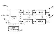
本発明は、図2に示されるような送信システム10に関連し、送信システム10は、送信機12から受信機16に情報を配信するために複数のサブチャネルを利用する。様々なサブチャネルからの信号は連続的にデコードされる。デコードの順序は受信機16にて決定され、送信機12には知らされない。送信機12は、順序づけること(ordering principle)を把握しており、整列したサブチャネルの容量(最大スループット)の統計値(例えば、レイリーフェージング)のようなサブチャネルの順序シーケンスについてのいくつかの性質を把握しているものとする。或いは、送信機12は順序づけられたサブチャネルの信号対雑音(及び干渉)比(SNR/SINR)を把握し得る。しかしながら、サブチャネルの各々の解釈に対するデコードの順序は、送信機12から見てランダムである。本発明は、そのような複数チャネル送信システム10の実効性を増進させるために、サブチャネルに関する既知の特性を利用するチャネル符号化法に関連する。このチャネル符号化法は、エンコーダ及びデコーダアーキテクチャを利用する。一般的な符号化は、更に、無線送信システムの実効性を増進させるために適用され、そのシステムは、複数の並列的なデータストリームを送信するための複数の送信アンテナと、整列順干渉相殺(OSIC)と言及される、送信されたストリームの順次的抽出に関する受信機における複数の受信アンテナとを利用する。 The present invention relates to a
先ず、提案されるチャネル符号化法の基本概念を説明する。このため、2つのサブチャネルを想定する。2つのデータストリームが、それぞれ容量C1,C2(チャネル利用当たりのユーザビット又は情報ビットで測定される)を有する2つのサブチャネルを介して送信され、これらの容量C1,C2は送信機に既知であるものとする。但し、送信されたストリームとサブチャネルとの間の関連性は送信機12には未知であるとする。受信機16では、データストリームが、任意的な順序ではあるが同時的ではなく連続的にデコードされる。明らかに、そのようなシステムの最大利用可能容量は、(C1+C2)を上限とする。直接的な手法は、双方のデータストリームをエンコードするためにユーザビットの独立した2つの集合を利用することである。データストリームとサブチャネルとの間の対応関係は送信機12には未知であるので、各データストリームのビットレートは、min(C1,C2)である容量の最小値により制限される。仮に、より高いビットレートが使用されるならば、データを失う危険性がある。従って、2つのサブチャネルにわたる最大の累積的ビットレートは、2min(C1,C2)である。このレートは、|C1−C2|の分だけ上限値(C1+C2)より小さい。以下に説明されるチャネル符号化法は、全容量(C1+C2)を利用可能にする。First, the basic concept of the proposed channel coding method will be described. For this reason, two subchannels are assumed. Two data streams are transmitted over two subchannels with capacities C1 and C2 (measured in user bits or information bits per channel usage), respectively, and these capacities C1 and C2 are transmitted It shall be known to the machine. However, it is assumed that the relationship between the transmitted stream and the subchannel is unknown to the
一般性を失うことなく、C1≧C2であるとすることができる。データストリームは、同じ大きさのユーザビットの2つの交わる集合を用いてエンコードされる。具体的には、各ストリーム内で、独立ビット(共有されない情報要素)及び共通ビット(共有される情報要素)の数が選択され、両ストリームが等しいビットレートC1を有するが、第2ストリームを考慮した第1ストリームの条件付ビットレート(即ち、第1ストリームの独立/未知ビットのみ)は、C2に等しい。言い換えれば、各ストリームについてのデータブロックをエンコードするユーザビットの総数はNC1であり、2つのブロック内での共通ビット数はN(C1−C2)であり、ここでNは包含されるチャネルユーザ数(又は信号次元)である。この原理は図1に図示されており、2つのデータストリームをエンコードするユーザビットの集合が、2つの楕円で図示されている。ユーザビットの各集合は、チャネル特性に合致するコードによる、Nチャネルシンボルのコードワード又は符号語を定める。例えば、(理想的には)ガウシアンコードが、加法性ガウス雑音(AWGN)に使用される。2つのサブチャネル上で伝送されるユーザビット総数は、N(C1+C2)であり、ここで、ビットレート全体は(C1+C2)であることに留意を要する。It can be assumed that C1 ≧ C2 without loss of generality. The data stream is encoded using two intersecting sets of user bits of the same size. Specifically, within each stream, the number of independent bits (information elements not shared) and common bits (information elements that are shared) is selected, but having a bit rate C1 both streams are equal, a second stream considering the first stream of conditional bit rate (i.e., the first stream independent / unknown bit only) is equal to C2. In other words, the total number of user bits encoding the data block for each stream is NC1 and the number of common bits in the two blocks is N (C1 -C2 ), where N is included. The number of channel users (or signal dimension). This principle is illustrated in FIG. 1, where a set of user bits encoding two data streams is illustrated by two ellipses. Each set of user bits defines a codeword or codeword of N channel symbols with a code that matches the channel characteristics. For example, (ideally) a Gaussian code is used for additive Gaussian noise (AWGN). Note that the total number of user bits transmitted on the two subchannels is N (C1 + C2 ), where the overall bit rate is (C1 + C2 ).
受信機では、これらのデータストリームは、目下の例では容量C1のサブチャネルであるところの最良のサブチャネルから始まり、連続的にデコードされる。明らかに、最良のサブチャネルのデコード処理は、NC1ユーザビット総てを生成する。ユーザビットの2つの集合の間の共通部分又は交差部に起因して、残りの第2の(最悪の)サブチャネルの未知ユーザビット数は、NC2である。第2サブチャネルに関する条件付ビットレートは、第1チャネルのデコード後にC2になる。このレートは第2サブチャネルの容量に等しいので、第2データストリームの残余のNC2ユーザビットはデコードされ得る。At the receiver, these data streams, the present example starts from the best subchannel where a sub-channel capacity C1, is continuously decoded. Obviously, the best subchannel decoding process produces all NC1 user bits. Due to the common portion or intersection between the two sets of user bits, unknown users bit number of the remaining second (worst) subchannel is NC2. The conditional bit rate for the second subchannel is C2 after decoding the first channel. Since this rate is equal to the capacity of the second subchannel, the remaining NC2 user bits of the second data stream can be decoded.
図2のブロック図には、任意のサブチャネル数mを有し、受信機16にて対応するデータストリーム及び順序付けられた容量の既知シーケンスに関する整列順デコードを行なう送信システム10の概要が図示されている。図2によれば、ユーザビットの集合は、チャネルエンコーダ8によって、m入力m出力チャネル14上を伝搬するm個の並列的ストリームにエンコードされる。このチャネル14は、各々の容量C1,...,Cmと共にm個の並列的サブチャネルが続くm個の送信ストリームに関する置換又は順列π(permutation)によって表現される。容量の集合は、受信機16にとって及び送信機12にとって既知であるが、その順列πは受信機16に対してのみ既知である。送信機12は、πをランダム的順列として取り扱う(特に、πは、m個の可能な置換の集合にて一様に分布していることが想定される)。一般性を失うことなく、受信ストリームは、C1≧...≧Cmのように並べられるものとする。受信機16において、これらのストリームは、m個のデコーダ18によって連続的にデコードされ、n番目のデコーダ18は、先行する(n−1)個のデコーダ18(1<n≦m)によって復元されたユーザビットに関する知識を利用する。m個のデコーダ18及びそれらの相互接続は、チャネルデコーダを形成する。The block diagram of FIG. 2 shows an overview of a
以下、図2の多入力多出力(MIMO)チャネル14に対するエンコード/デコードを説明し、この手法により達成可能な最大スループットを示す。このチャネル14の容量を指定するために、0≦n<mの大きさで、実数値のシーケンス{Sk}1≦k≦mに適用される有限差分演算子(finite difference operator)In the following, encoding / decoding for the multiple-input multiple-output (MIMO)

m=2に関して上述したチャネル符号化法は、任意のmに拡張される。第1段階として、集合C1...Cmを定める必要があり、この集合は、可能な最大の総和(C1+・・・+Cm)に関して上記2つの条件を満足するものである。この要請又は問題は、標準的な線形プログラミングによって解決され得る。所与の容量の集合C1...Cm及びチャネルユーザ数Nに関し、以下に説明されるユーザビット区分化(UBP:user bit partitioning)アルゴリズムに従って、m個のサブチャネル上で伝送される情報ビットI1...Imに関するm個の交差する集合を指定する。このアルゴリズム及び以後の本明細書の記載において使用する表記法を列挙する:The channel coding method described above for m = 2 is extended to any m. As a first stage, the setC1 . . .Cm needs to be defined, and this set satisfies the above two conditions with respect to the maximum possible sum (C1 +... +Cm ). This requirement or problem can be solved by standard linear programming. A given set of capacitiesC1 . . .Cm and the number of channel users N, the information bits I1 ... Transmitted on m subchannels according to the user bit partitioning (UBP) algorithm described below. . . To specify the m-number of intersecting set about Im. List the notation used in this algorithm and the rest of this document:
各集合Ikは、データブロック内のユーザビットの指標又はインデックスの集合として解釈され、それはk番目(1≦k≦m)のサブチャネル上で伝送される。従って、MIMOチャネルを特徴付ける容量C1...Cmの集合を考慮して、集合I1...Imがオフラインで指定される。図3に、送信機12の一般的なブロック図が示されている。先ず、送信されるデータブロック(即ち、情報信号21のユーザビット)は、UBPアルゴリズム22に従って、デマルチプレクサ20によって、m個のストリーム/情報サブ信号23に区分化/分離される。実際には、これらのストリーム23の各々はD1ユーザビットを含み、任意のnストリームはDnユーザビットを共用する(1<n≦m)。これらm個のストリーム23は、更に、m個のエンコーダ24により同一コード(identical code)と共にチャネルシンボル25のシーケンスにエンコードされ;これらのコードは、そのチャネル属性に適合されるべきである。m個のエンコーダ24はチャネルエンコーダ8を形成する。受信機16では、シンボル25に関してエンコードされたシーケンス(又はエンコードされた情報サブ信号25)は、容量C1...Cmに従って順序付けられ、図2に示されるように、以後デコードされる。ここで、総てのm個のデコーダ18が同一構造を有する。更に、n番目のストリームのデコーダ18は、n番目の入力ストリームから既知のDnユーザビットを利用し、そのユーザビットは先行する(n−1)ストリーム(1<n≦m)を共用する。
最適に選択されたコード及び適切なデコードアルゴリズムを利用するこのような手法は、上記(2)式に示される容量CΣに到達する可能性を有することが立証され得る。各データストリームについてエンコーダ/デコーダを選択することには、特に注意を払う価値がある。受信機における最尤(ML:maximum likelihood)デコードに関するランダムコードは、最大スループットを示唆する。しかしながら、エンコード及びデコードはこれらのコードに適切ではない。コード及び対応するデコードアルゴリズムの実際の選択は、望まれるパフォーマンス特性(ビット及びフレームエラーレート)及び複雑さ/格納容量の制限に依存する。多くの場合に、各サブチャネルは、充分に把握された性質を有するスカラーチャネルであり、これにより標準的なチャネルコードを生じさせる。実際に有益ないくつかの例が以下に説明される。Such an approach utilizing an optimally selected code and an appropriate decoding algorithm can be proved to have the potential to reach the capacity CΣ shown in equation (2) above. It is worth paying particular attention to selecting an encoder / decoder for each data stream. A random code for Maximum Likelihood (ML) decoding at the receiver indicates maximum throughput. However, encoding and decoding are not appropriate for these codes. The actual choice of code and corresponding decoding algorithm depends on the desired performance characteristics (bit and frame error rate) and complexity / storage capacity limitations. In many cases, each subchannel is a scalar channel with a well-understood nature, thereby producing a standard channel code. Some practically useful examples are described below.
先ず、加法性ガウス雑音の影響を受けるMIMOフェージングチャネルを有する送信システムが説明される。この場合において、各サブチャネルの出力における信号は、総てのサブチャネルで伝送されるシンボル及び加法性ガウス雑音の線形結合で与えられる。このような場合における受信機16での適切な処理に関し、各サブチャネルは、残留サブチャネル間干渉及び加法性ガウス雑音によって劣化したスカラーチャネルとして取り扱われる。共通に使用される符号化手法は、ビット空間エンコードすること(FECエンコーダ)、符号化ビットをチャネルシンボルにマッピングすること、及びこれらのシンボルをチャネルに配置すること(復調)より成る。最後のステップは、チャネルの特性に依存する。通常的には、復調は時間領域(単一キャリアシステム)又は周波数領域(複数キャリアシステム)で実行される。何れの場合も、拡散が適用され、いくつかのチャネルシンボルが時間又は周波数領域でいくつかのチャネルを共用するようにすることが可能である(それぞれ直接シーケンス又はマルチキャリア拡散スペクトル伝送となる)。チャネルシンボルアルファベット(alphabet)(信号送信)の選択は、所望のスペクトル効率及びFECレートに依存する。共通に使用される信号化法は:BPSK,QPSK,8−PSK及び2k−QAM(k≧2)である。提案されるエンコード手法は、そのようなMIMOフェージングチャネルに適用され得ることに留意を要する。このため、容量C1...Cmを指定する必要があり、これらは、各サブチャネルにおける信号対干渉プラス雑音比(SINR)によって特徴付けられる。フェージングチャネルの場合には、SINRは送信機12には未知である。標準的な手法は、アウテージ(outage)チャネルに関する小さな部分集合を除く総てについて、実際の未知のSINRに準拠する下限値のように、フェージングに関する予測される統計的性質に従って、選択されるSINRのアウテージ値を利用することである。SINR/容量/等のアウテージ値は、アウテージレートが、システムの実際のSINR/容量/等がそのアウテージ値より悪化した場合の状況/時間の所定の割合に等しいところのSINR/容量/等の値であることに留意を要する。First, a transmission system having a MIMO fading channel that is affected by additive Gaussian noise is described. In this case, the signal at the output of each subchannel is given by a linear combination of the symbols transmitted on all subchannels and additive Gaussian noise. For proper processing at the
ガウス雑音を有するチャネルに一般的に使用されるFEC符号化は、標準的な畳込み符号であり、最近では、並列的及び直列的に連結されたインターリーブされる(ターボ)符号や、低密度パリティチェック(LDPC)コードである。これら総てのコードは図3のエンコーダ24内に組み込まれ得るが、その手法の効率は選択されるFECコードの特性に依存する。実際、FEC24の入力における既知ユーザの誤り訂正能力は、既知ビットを包含する典型的なエラーパターンの間隔又はスパンに依存する。LDPC及びターボ符号のようなランダム状のコードの場合には、典型的なエラーパターンは、符号ビットの大部分にわたる。従って、エンコーダ24の入力における既知ビット全体は、(畳込み符号の場合のローカルな又は局所的な効果とは異なり)コード全体にわたってグローバルな又は全体的な誤り訂正効果を備えるように期待される。従って、本件で説明される一般的なMIMOエンコード法にとって、ターボ符号、LDPC又は同様な符号FECコードを利用することは特に有利であることが期待される。そのようなFECコードに関し、他のエンコーダ24の入力にも寄与するn番目のエンコーダ24の入力におけるこれらユーザビットは、nエンコーダ24(1≦n≦m)の入力におけるユーザビットのストリーム内で一様に分布し得る。そのような分布は、マルチプレクサ20及びチャネルエンコーダ8の間に接続されたインターリーバ(図示せず)によってなされ、インターリーバは、図3に示されるように、(例えば、ターボ又はLDPCコードによって)FECエンコード化に先立って、デマルチプレクサ20の出力にてユーザビット23の各ストリームについて疑似ランダム(一様)又は等距離インターリーブを実行する。インターリーバは選択されるFECコードに更に最適化され得る。 FEC coding commonly used for channels with Gaussian noise is a standard convolutional code, and recently, interleaved (turbo) codes connected in parallel and in series, low density parity, and so on. Check (LDPC) code. All these codes can be incorporated into the
一般的なデコード法は、図2の受信機16に示される。n番目のデコード段において、n番目のデコーダ18が、先行する(n−1)段にてデコードされた符号と共に共用される既知入力ビットを利用することを図は示す。この概念の実際的な実現化は、コード種別及び対応するデコード手順に依存する。我々は、ソフト及びハード判定デコーダを区別する。ハード判定デコードでは、FECデコーダはその入力ユーザビットにて2進判定内容を生成する。共用ビットにおけるこれらの判定内容(情報要素)は、以後のデコード段階で、可能なコードワードの選択肢を限定するために使用される。 A general decoding method is shown in the
具体例:畳込み符号化に関し、入力ビットにおける2進判定内容は、通常的には、ビタビアルゴリズムによるMLシーケンス検出から得られる。共用ビットにおける判定内容は、一連のデコード段のビタビアルゴリズムに導入され、以前にデコードされた共用ビットに関連するトレリスセクション全体において、デコードされた2進値に対応するこれらの状態遷移のみが考慮されるようにする(通常のビタビアルゴリズムが適用される場合に、可能な遷移総数を2だけ減少させる。)。 Specific example: With regard to convolutional coding, the contents of binary determination in input bits are usually obtained from ML sequence detection by the Viterbi algorithm. Decisions on shared bits are introduced into a series of decode stage Viterbi algorithms, and only those state transitions corresponding to decoded binary values are considered throughout the trellis section associated with previously decoded shared bits. (If the normal Viterbi algorithm is applied, the total number of possible transitions is reduced by 2).
ソフト判定でコードでは、FECデコーダは、入力ビットの信頼性尺度を表現する(ソフト)実数値メトリックを生成する。通常的には、各ソフトメトリックは、(近似的な)対数尤度比(log−likelihood ratio)であり、即ち、観測される信号に対して、0になる入力ビットの経験的確率とこのビットが1である経験的確率との比率の対数である。ソフトメトリックは、しばしば連結された符号のデコード手順及び反復的デコードアルゴリズム内に含まれる。入力ビットに関する最終的な判定は、そのようなソフトメトリックの符号に従ってなされる。入力ビットに関するソフト判定が可能な場合は常に、2進判定内容(又は等価的に、非常に大きなソフト的値)の代りに、以後のデコード段で共用されるビットについてのソフトメトリックを利用することは、一般に良好な特性を保証する。 In code with soft decisions, the FEC decoder generates a (soft) real-valued metric that represents a reliability measure of the input bits. Typically, each soft metric is a (approximate) log-likelihood ratio, ie, the empirical probability of the input bit being zero and this bit for the observed signal. Is the logarithm of the ratio to the empirical probability that is 1. Soft metrics are often included within a concatenated code decoding procedure and an iterative decoding algorithm. A final decision on the input bits is made according to the sign of such soft metrics. Use soft metrics for bits shared in subsequent decoding stages instead of binary decisions (or equivalently very large soft values) whenever soft decisions on input bits are possible Generally guarantees good properties.
具体例:ソフト判定デコードは、ターボ符号及びLDPC符号を反復的にデコードするために一般的に使用される。ターボ符号の場合には、入力ビットのソフトメトリックは、組成符号に関するソフト入力ソフト出力(SISO)デコーダによって生成される。LDPCコードの場合は、そのソフトメトリックは、いわゆるメッセージ伝送デコードアルゴリズムから生じる。そのようなFECコードが、本明細書に説明されるMIMO符号化法の中で使用される場合はいつでも、現段階での最終的反復にて得られた、共用されるビットのソフトメトリックは、以後のデコード段に伝達される。以後の段階では、いわゆるソフトメトリックは、共用ビットに関する経験的なメトリックとして移用され、又はこれらのデコード段にて利用可能ならば、現存する経験的メトリックに加えられる。 Specific example: Soft decision decoding is commonly used to iteratively decode turbo codes and LDPC codes. In the case of a turbo code, the soft metric of the input bits is generated by a soft input soft output (SISO) decoder for the composition code. In the case of an LDPC code, the soft metric comes from a so-called message transmission decoding algorithm. Whenever such an FEC code is used in the MIMO coding method described herein, the shared bit soft metric obtained in the final iteration at this stage is It is transmitted to the subsequent decoding stage. In later stages, so-called soft metrics are diverted as empirical metrics for shared bits, or added to existing empirical metrics if available in these decoding stages.
最後に、デコード段全体において、所与の入力ビットが1以上の先行する段で共用される場合はいつでも、デコーダは、最も最新のデコード内容から得られる(ハード又はソフト)判定を利用することが望ましく、即ち、チャネルデコーダは、最も最近デコードされた情報サブ信号中の共用される情報要素を組み込むことで、受信したエンコード済み情報サブ信号をデコードするよう構成されることが望ましい。 Finally, throughout a decode stage, whenever a given input bit is shared by one or more preceding stages, the decoder may make use of the (hard or soft) decision obtained from the most recent decoded content. Preferably, the channel decoder is preferably configured to decode the received encoded information sub-signal by incorporating a shared information element in the most recently decoded information sub-signal.
反復的なデコードは、提案されるMIMO技法の実効性を改善するよう適用され得る。図2の手法に関する反復的デコードは、全デコードサイクルの全部又は一部を反復することを意味し、そのサイクルは上述したようなm個のサブチャネルを連続的にデコードすることから成る。この場合に、初期のデコード段は、先行する反復中に以後の段で取得した共用ビットについてのハード/ソフト情報を利用することができる。ソフト判定デコードの場合は、同様な情報に関する二重の演算を回避するために、他の段にて使用される信頼性値が、ターボデコードと同様に、外部情報(extrinsic information)に関する標準的な規則に従って算出されるべきである。 Iterative decoding can be applied to improve the effectiveness of the proposed MIMO technique. The iterative decoding for the technique of FIG. 2 means repeating all or part of the entire decoding cycle, which consists of successively decoding the m subchannels as described above. In this case, the initial decoding stage can use the hardware / software information about the shared bits obtained in the subsequent stage during the preceding iteration. In the case of soft decision decoding, in order to avoid double operations related to similar information, the reliability value used in the other stages is a standard value related to external information (extrinsic information) as in turbo decoding. Should be calculated according to the rules.
2進MIMO伝送チャネルに同一のチャネル符号化法が適用され得る。可能な手法は、複数の経路(サブチャネル)を通じて送信機から受信機にネットワーク内で2進メッセージ(データパケット)を伝送することである。様々な経路の正確な信頼度(等価的2進対称チャネルの重複する又はクロスオーバする確率)は、送信機に知られていないが、統計的特性(クロスオーバ確率の分布測)は、例えばモデリング結果から既知であるものとする。サブチャネル毎の信頼度の不定性を取り扱う1つの手法は、並べられたサブチャネルの信頼度が非増加的(non−increasing)シーケンスを形成するような順序で、これらのストリームをデコードすることである。実際には、独立に等しく分布したランダム値の順序シーケンスに関する各要素の変動は、そのシーケンス長が無限大向かうにつれてゼロに向かう。従って、それらの数が充分に大きいことを条件に、順序付けられたサブチャネルの(準決定性の)スループットに対する伝送レートを正確に採用することが可能になる。順序付けられたサブチャネルのスループットは、送信機にて正確に知られるものと想定され得るが、(チャネル情報を伝搬するために送信機と受信機の間にフィードバックチャネルが使用されていない限り)送信されるストリームの抽出の順序は未知である。そのような場合には、全体的なMIMOチャネルは、図2の一般的手法の範疇に収まる。更なる実施例は、2進対称チャネルに対する(即ち、MDSコードと共に)利用可能なFEC手法に準拠することが可能である。本明細書で説明されるチャネル符号化法に従って、入力ビットに関する部分的知識の恩恵を強調するように、既存の符号化法を採用することが望ましい。 The same channel coding method may be applied to the binary MIMO transmission channel. A possible approach is to transmit binary messages (data packets) in the network from the transmitter to the receiver through multiple paths (subchannels). The exact reliability of various paths (probability of overlapping or crossover of equivalent binary symmetric channels) is not known to the transmitter, but the statistical properties (distribution measure of crossover probability) are for example modeling It shall be known from the results. One approach to handling reliability uncertainty for each subchannel is to decode these streams in an order such that the reliability of the arranged subchannels forms a non-increase sequence. is there. In practice, the variation of each element for an independently equally distributed random value ordered sequence goes to zero as the sequence length goes to infinity. Therefore, it is possible to accurately adopt the transmission rate for the (sub-deterministic) throughput of the ordered subchannels, provided that their number is sufficiently large. The throughput of the ordered subchannel can be assumed to be known exactly at the transmitter, but transmitted (unless a feedback channel is used between the transmitter and receiver to propagate the channel information). The order of stream extraction is unknown. In such a case, the overall MIMO channel falls within the general approach of FIG. Further embodiments may be compliant with available FEC techniques for binary symmetric channels (ie, with MDS codes). In accordance with the channel coding method described herein, it is desirable to employ existing coding methods to emphasize the benefit of partial knowledge about the input bits.
また、上述したチャネル符号化法は、複数の送信及び受信アンテナを利用する無線通信システムのスループットを増進するようにも適用され得る。そのようなシステムでは、複数の送信アンテナ28は、同一のデータソースから発する符号化シンボルのストリームを送信するために使用される。受信機側では、これら複数のストリームが抽出され、同時に又は連続的にデコードされる。異なるストリームの同時デコードは、非常に大きな演算負担を要し、その演算労力は、総てのアンテナ28で送信されるチャネル利用毎の全ビット数に関して指数関数的に増加する。従って、同時デコードは、理論的スループットに比較して小さなデータレートに対してのみ適切である。ここでは、連続的デコード法に着目し、各データストリームは、先行段で復元されたデータストリームを除去すること、空間的な(空間−時間、又は空間−周波数)干渉相殺による、複数受信アンテナ40による、残余データストリームをキャンセルすることによって復元される。特に、連続的干渉相殺(OSIC)を利用する手法を考察する。
The channel coding method described above may also be applied to increase the throughput of a wireless communication system that uses multiple transmit and receive antennas. In such a system, multiple transmit
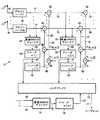
OSIC法を利用するベースラインシステムは、欧州特許出願EP0951091A2に開示されている。公知のこのシステムによると、ユーザビット21の合計が、m個の対称的なストリーム23に分離される。各ストリーム23は、(エンコーダ24による)等しいエンコード及び(変調器26による)変調に委ねられ、m個のアンテナ28の内の1つによって送信される。そのような送信機12のブロック図が、図4に示される。受信機16は、M個の信号出力を生成するM個のアンテナ40を使用する。受信機16は、図6に概略的に示されるようなOSIC法を利用する。MIMOチャネルの伝達関数は受信機にて既知であり又は正確に推定されるものとする(例えば、送信機から送信された基準信号に基づく、標準的なトレーニングシーケンスによって推定される。)。このMIMO伝達関数は、概してM×m型の行列Hによって記述され、行列要素又は項目Hq,pは、p番目の送信アンテナ28とq番目の受信アンテナとの間の伝達関数を表す。周波数選択性フェージングの場合は、Hの行列要素は、そのチャネルの時間領域又は周波数領域の特性を表す関数である。非選択性(平坦な又はフラットな)フェージング環境では、Hは複素行列要素値を有する。A baseline system using the OSIC method is disclosed in European
受信したエンコード済み情報サブ信号は、復調器42にて復調される。既知のHに基づいて、受信機16は、変調されたストリーム41から連続的にm個のストリーム(情報サブ信号)を抽出する。第1(最も左側)の階層又は段階(MMSEキャンセラ44、デコーダ46、エンコーダ48、乗算器56及び減算器60より成る)では、ストリーム41の1つが、他の(m−1)ストリーム41からの寄与をキャンセルすることによって、抽出される。一般性を失うことなしに、第1階層で抽出されたストリームのインデックス又は指標は、π[1]であるとする。既知のシステムでは、これらのストリームの完全な相殺は、このストリームに関連付けられるチャネル伝達関数のベクトル The received encoded information sub-signal is demodulated by the
MIMO送信システムのスループット又は処理能力は、SINR値 The throughput or processing capacity of the MIMO transmission system is the SINR value.
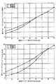
図4,図6各々における送信機12及び受信機16、(3)により指定されるようなMMSE相殺フィルタ、(4)により規定されるような統計的判定、及び(5)により規定されるような処理順序と共に上述したようなMIMO送信システムは、本明細書ではベースラインシステムとして取り扱われる。そのようなシステムの理論的に達成可能なスループットを分析する。充分に非相関性の送信/受信アンテナで狭帯域(非選択性)レイリーフェージングを想定する。これは、チャネル行列の要素が、複素次元に関してゼロ平均及び分散(1/2)の統計的に独立な複素ガウス型変数であることを意味する。先ず、2つの送信/受信アンテナのシステムを考察する:M=m=2。この形態では、双方のレイヤについてのアウテージ比率SINRπ[1](1)及びSINRπ[2](2)は、受信アンテナ当たりの全体的SNRの広い範囲に対する100000回の独立モンテカルロ試行によって推定された(即ち、全送信アンテナからの平均的全信号電力と任意の受信アンテナでのノイズ電力との比率)。10%及び1%のアウテージレートについての経験的なSINR値は、図8にプロットされている(アウテージレート10%(上図)及び1%(下図)、送信アンテナ2つ、受信アンテナ2つ、非相関性レイリーフェージングの場合の、レイヤ/段毎のアウテージSINRと受信アンテナ当たりの全体的SNRとの関係を示す。)。標準的な関係式
C=log2(1+SINR)[ビット/チャネル利用] (6)
に従って算出された容量(最大スループット)の対応するアウテージ値は、図9にプロットされている(アウテージレート10%(上図)及び1%(下図)、送信アンテナ2つ、受信アンテナ2つ、非相関性レイリーフェージングの場合の、レイヤ/段毎のアウテージスループットと受信アンテナ当たりの全体的SNRとの関係を示す。)。小さなほどほどのSNRでは、第1の(最も左側の)レイヤが、より大きなスループットを有することが見受けられる。このような挙動は、低いSNRでは、加法性のノイズ寄与がノイズ及び残留する干渉の中で支配的であり、それ故に、第1レイヤで利用可能な最良のサブチャネルの選択は、このレイヤのより良い容量になることに起因する。残留干渉はSNRの増加と共により重要化し、このことは、高いSNRでは第1レイヤが第2レイヤに比べて劣化していることを説明する。また、第2レイヤと比較した第1レイヤの利点も、設定されるアウテージレートに依存する。第1レイヤの最大スループットは、実際のある場面では第2レイヤのスループットの近似的に2倍程度の大きさである。即ち、アウテージ10%及び劣化の6−8dB程度のSNRの領域は、CDMAのような干渉の抑制された環境でのセルラ通信に適切であり得る。4 and 6 respectively,
The corresponding outage values of the capacity (maximum throughput) calculated according to the above are plotted in FIG. 9 (
このセクションで上述したように、ベースラインシステムでの各サブチャネルのスループットは、別のレイヤで観測されるスループットの最小値を超えない。従って、ベースラインシステムの最大の全体的スループットは、これらのスループットの最小値の2倍である。図10の「菱形」でプロットした曲線は、アウテージレート10%(上図)及び1%(下図)のアウテージレートの場合の、ベースライン(標準的)システムの全体的スループットと全体的SNRとの関係を示す。 As described above in this section, the throughput of each subchannel in the baseline system does not exceed the minimum throughput observed in another layer. Thus, the maximum overall throughput of the baseline system is twice the minimum of these throughputs. The curves plotted with “diamonds” in FIG. 10 show the overall throughput and overall SNR of the baseline (standard) system for outage rates of 10% (top) and 1% (bottom). Shows the relationship.
この場合において、全体的スループットは、SNR及びアウテージレートの領域における2つのレイヤのスループットC1,C2の総和を上限に増加することに留意を要する(但し、C1≧C2である)。実際、図4の送信機14及び図6の受信機16を備えた送信システムは、図2の一般的送信手法の特殊な場合であり、容量C1...Cmは、レイヤ1乃至mにて達成可能なアウテージスループットを表し、置換πは送信されたストリームの処理する順序を定めることに留意を要する。アウテージスループットC1...Cmの集合は、想定される伝搬環境の統計的記述によって定められる(目下の例では、非相関性レイリーフェージング)。通常的には、これらのスループットはオフラインで測定され、送信機12にとって及び受信機16にとって既知であることが想定される。置換πはチャネル具現化(realisation)に依存する。この置換は、受信機16にて定められ、推定されるチャネル行列に委ねられ、それ故に送信機12には未知である。従って、ベースライン送信システムは、図2で説明したような一般的手法に該当し、それ故に上述した一般的チャネル符号化がこの場合に適用される。2つの送信/受信アンテナの場合には、エンコードは上述したように実行される。8dB及び10%アウテージレートのSNRにて非相関性レイリーフェージングの存在する中で動作しなければならないエンコーダを設計することを考察する。この場合に、レイヤ1及び2で達成可能なスループットは、図9にそれぞれ示されるように、チャネル利用当たりC1≒1.27及びC2≒0.81ユーザビットである。従って、これらのレイヤに関する実際に達成可能なスループットは、C1及びC2による上限に制限される。エラーレートの観点からのQoS要請を満足するために、スペクトル効率の(僅かな)一部が犠牲になるので、その上限値は現実には決して達成されない。その一部分は、FEC及びQoS要請に関する所望の属性に依存する。実際のスループットの決定は、本明細書では特別には意図されていないFEC設計内容に関連する。従って、目下の例では、最大スループットが達成され得るような理想的なFECを想定する。送信されるデータのブロックがN=100チャネルを利用するものと仮定する。これは、例えばそのチャネルに対して所定のアルファベット順に送信される100シンボルのブロックに対応する。セクション1での説明によれば、NC1≒127の等しいサイズのユーザビットの2つの集合を形成する必要があり、これらの集合は、N(C1−C2)≒127−81=46ユーザビットを共用する。これら2つの集合は、独立してエンコードされ、変調され、別々のアンテナを通じて送信される。受信機16では、このセクションにて上述したように、データストリームの標準的なOSIC抽出が実行される。(5)式によって受信機にて決定される処理順序πに従って、ストリームπ[1]が第1の(最左の)レイヤで抽出される。このレイヤのアウテージスループットはC1であるので、対応するNC1≒127ユーザビットが連続的にデコードされる。これらユーザビットの内46は、ストリームπ[2]と共用されることを想起されたい。第2レイヤでは、π[2]が抽出される。このストリームのデコーダは、全127ビットの内46ユーザビットの知識による恩恵を受ける。残りのNC2=81ユーザビットは、第2レイヤのスループットがC2≒81であるので、連続的に復元され得る。In this case, it should be noted that the overall throughput increases up to the sum of the throughputs C1 and C2 of the two layers in the SNR and outage rate regions (where C1 ≧ C2 ). . Indeed, transmission system with a
本願にて提案されるチャネル符号化法は、チャネル利用当たりの全体的スループット(C1+C2)≒2.08ビットを達成し、これはチャネル利用当たりの全体的スループット2C2≒1.62を有するベースラインシステムと比較して28%の改善である。ベースラインシステムのスループット及び後者の提案される修正内容は、様々なSNR並びに10%及び1%のアウテージレートに関して図10にプロットされている。修正された送信システムのベースラインシステムと比較した改善効果は、低くほどほどのSNRでは、10%乃至100%高く変化する。The channel coding method proposed in this application achieves an overall throughput per channel utilization (C1 + C2 ) ≈2.08 bits, which results in an overall throughput per channel utilization of 2C2 ≈1.62. This is a 28% improvement over the baseline system we have. Baseline system throughput and the latter proposed modification are plotted in FIG. 10 for various SNRs and 10% and 1% outage rates. The improvement of the modified transmission system compared to the baseline system varies from 10% to 100% higher at lower SNRs.
一般的なM及びmの場合には、修正されたベースラインシステムの送信機は図5と同様であり、ユーザビットに関するm個の交差する集合を生成するためにアルゴリズム1が適用される。これらの集合は、エンコードされ、変調され、m個の送信アンテナを通じて並列的に送信される。修正されたベースラインシステムの受信機は図7に提示される。図6の従来の受信機と比較するに、修正された受信機は選択ブロック78を有し、このブロックはゲート80を通じて先行するレイヤでデコードされた共用されるユーザビット(関連するハード/ソフト判定内容)を、後続のレイヤのデコーダに転送することを制御する。 For the general M and m case, the modified baseline system transmitter is similar to FIG. 5 and
残りの部分では、M=m=3のMIMO送信システムに関し、UBPアルゴリズムを用いてユーザビット区分化を行なう幾分複雑な例を与える。非相関性レイリーフェージングの想定される状況にて、図11乃至13に示されるように、様々なレイヤ、広範囲にわたるSNR及び10%,1%のアウテージレートの場合に、レイヤ毎の対応するアウテージスループット、ベースライン(標準)システム及び修正されたシステムに関する全体的アウテージスループットで達成可能なアウテージSINRを算出した。図11は、アウテージレート10%(上図)及び1%(下図)の場合のレイヤ/段当たりのアウテージSNRと受信アンテナ当たりの全体的SINRとを示し、送信システムは、3つの送信アンテナと3つの受信アンテナを有し且つ非相関性レイリーフェージングに委ねられる。図12は、アウテージレート10%(上図)及び1%(下図)の場合のレイヤ/段当たりのアウテージスループットと受信アンテナ当たりの全体的SNRとを示し、送信システムは、3つの送信アンテナと3つの受信アンテナを有し且つ非相関性レイリーフェージングに委ねられる。図13は、アウテージレート10%(上図)及び1%(下図)の場合の標準的な及び修正されたシステムの全体的なアウテージスループットと受信アンテナ当たりの全体的SNRとを示し、送信システムは、3つの送信アンテナと3つの受信アンテナを有し且つ非相関性レイリーフェージングに委ねられる。 The rest gives a somewhat complicated example of user bit partitioning using the UBP algorithm for a MIMO transmission system with M = m = 3. In the assumed situation of uncorrelated Rayleigh fading, as shown in FIGS. 11-13, for various layers, a wide range of SNR and 10%, 1% outage rates, the corresponding outages per layer. The outage SINR achievable with the overall outage throughput for the stage throughput, baseline (standard) system and modified system was calculated. FIG. 11 shows the outage SNR per layer / stage and the overall SINR per receive antenna for an outage rate of 10% (top) and 1% (bottom). It has three receive antennas and is left to uncorrelated Rayleigh fading. FIG. 12 shows outage throughput per layer / stage and overall SNR per receive antenna for outage rates of 10% (top) and 1% (bottom), where the transmission system has three transmit antennas. And three receive antennas and is left to uncorrelated Rayleigh fading. FIG. 13 shows the overall outage throughput and overall SNR per receive antenna for standard and modified systems for outage rates of 10% (top) and 1% (bottom) The system has three transmit antennas and three receive antennas and is left to uncorrelated Rayleigh fading.
先ず最初に、最大スループットC1,C2,C3の集合を見出す必要があり、それらは(2)式に示されるような、適切な制約の下に全体的スループットCΣを与える。その結果生じる値C1,C2,C3は、図12に波線でプロットされる。総ての場合にC1=C1,C3=C3であるが、中間レイヤのスループットC2は、対応するC2より小さくなることが間々ある。上述したように、8dBのSNR、10%アウテージレート及びブロック当たりN=100チャネルを選択する。図12によれば、レイヤ毎の最大スループットは、C1≒1.51,C2≒1.33,C3≒0.95及びレイヤ毎の適切な最大スループットは、C1≒1.51,C2≒1.23,C3≒0.95であることが見出される。次に、ユーザビットの3つの集合を生成するためにアルゴリズム1を適用する。まず最初に、NC1=151,NC2=123,NC3=95及び対応するD1=NC1=151,D2=(NC1−NC2)=28,D3=((NC1−NC2)−(NC2−NC3))=0 を算出する。アルゴリズムの残りの部分は次のようにして実行される:
− D1=151ユーザビットの任意的集合としてI1を選択し;
− I1からD2=28ビットの第1ブロック(ビット1乃至28)を求め、I1に属しない(D1−D2)=123ユーザビットを加味することでI2=を取得し;
− I1からD2=28ビットの第2ブロック(ビット29乃至56)を求め、I2(I1と交わらない)からD2=28ビット(ビット29乃至56)の第2ブロックを加味し、I3を求めるために、I1ともI2とも共用されない((D1−D2)−(D2−D3))=95ユーザビットを加味する。
D3=0は、形成されるユーザビットの3つの集合が空集合であることを示す。より一般的な考察を行なう。任意のm≧3に対して、スループットC1...Cmが、C1及びCmの間で直線的に位置するならば、C1=C1,Cm=Cmであり、総てのC1...Cmが、C1及びCmを接続する(仮想的な)直線に沿って等しく位置を占める。この場合には、総てのm≧3に対してDn=0であり、従って任意の3つ(又はそれ以上)のユーザビットの集合の交わりは空集合である。この考察は、内部ループをp∈{(n−3),(n−2),(n−1)}に制限することによって、UBPアルゴリズムの一般的な形式を簡略化するために使用され得る。この簡略化は適切な大きなmに対して有意義である。First, it is necessary to find a set of maximum throughputsC1 ,C2 ,C3 , which gives an overall throughput CΣ under appropriate constraints as shown in equation (2). The resulting valuesC1 ,C2 ,C3 are plotted with dashed lines in FIG. In all casesC1 = C1 ,C3 = C3 , but the intermediate layer throughputC2 is often smaller than the corresponding C2 . As described above, an 8 dB SNR, 10% outage rate and N = 100 channels per block are selected. According to FIG. 12, the maximum throughput per layer isC1 ≈1.51,C2 ≈1.33,C3 ≈0.95, and the appropriate maximum throughput per layer isC1 ≈1.51, It is found thatC2 ≈1.23,C3 ≈0.95. Next,
-Select I1 as an arbitrary set of D1 = 151 user bits;
Obtaining a first block (
- determine theD 2 = 28 second block of bits (bits 29 through 56) from I1, in consideration of the second block ofD 2 = 28 bits (bits 29 through 56) from the I 2 (not cross theI 1) In order to obtain I3 , neither I1 nor I2 is shared ((D1 −D2 ) − (D2 −D3 )) = 95 user bits.
D3 = 0 indicates that the three sets of user bits to be formed are empty sets. A more general discussion. For any m ≧ 3, the throughput C1 . . . If Cm is located linearly between C1 and Cm , thenC1 = C1 ,Cm = Cm and all C1 . . . Cm occupies the same position along the (virtual) straight line connecting C1 and Cm . In this case, Dn = 0 for all m ≧ 3, so the intersection of any three (or more) sets of user bits is an empty set. This consideration can be used to simplify the general form of the UBP algorithm by restricting the inner loop to pε {(n−3), (n−2), (n−1)}. . This simplification is significant for the appropriate large m.
本発明の範囲は明示的に説明された態様に限定されない。本発明はこれら新規の特徴により及びそれらの特徴の組合せにより具現化される。参照符号は特許請求の範囲を限定するものではない。原文に記載の“comprising”なる語は、特許請求の範囲に列挙されたもの以外の要素又はステップの存在を排除しない。原文に記載の要素に先行する“a”又は“an”なる語は、そのような要素が複数存在することを排除しない。 The scope of the invention is not limited to the explicitly described embodiments. The present invention is embodied by these novel features and combinations of these features. The reference signs do not limit the scope of the claims. The word “comprising” in the text does not exclude the presence of elements or steps other than those listed in a claim. The word “a” or “an” preceding an element described in the text does not exclude the presence of a plurality of such elements.
Claims (20)
Translated fromJapanese− 前記情報信号を複数の情報サブ信号に分離するステップ;
−前記情報サブ信号をエンコードされた情報サブ信号にエンコードするステップ;
− エンコードされた情報サブ信号の各々を前記サブチャネルの1つを通じて前記受信機に送信するステップ;
を有し、前記分離するステップは、前記情報信号を、共用される及び共用されない情報要素を有する複数の部分的に重複する情報サブ信号に分離するステップを有し、各サブ信号についての共用される情報要素の配分は、前記受信機により要請されるサブチャネルのスループットに適合するようになされ、2つの異なる情報サブ信号間で共用される情報要素量は2つの異なるサブチャネル間のスループット差に依存するようにした方法。A method of transmitting an information signal to a receiver through multiple subchannels:
-Separating the information signal into a plurality of information sub-signals;
- the step of encoding the information subsignals encodedthe information sub-signal;
- sending tothe receiver a respective encoded information subsignal via one ofthe subchannels;
Having a step of the separation,the informationsignal,comprising the step of separating the plurality of partially overlapping information subsignals having information elements that are not shared by the and sharedareshared for each subsignal Theallocation of information elementsisadapted to the throughput of subchannels required by the receiver, and theamount of information elements shared between two different information subsignals is the difference in throughput between the two different subchannels. Howto make it dependent .
− 受信したエンコードされた情報サブ信号を連続的にデコードするステップ;
を有し、前記エンコードされた情報サブ信号は、共用される及び共用されない情報要素を含む部分的に重複するエンコードされた情報サブ信号であり、連続的にデコードするステップは、既にデコードした情報サブ信号の共用される情報要素を利用し、前記受信したエンコードされた情報サブ信号中のエラーを訂正することで、前記受信したエンコードされた情報サブ信号をデコードするステップを有し、各情報サブ信号についての共用される情報要素の配分は、前記受信機により要請されるサブチャネルのスループットに適合するようになされ、2つの異なる情報サブ信号間で共用される情報要素量は2つの異なるサブチャネル間のスループット差に依存するようにした方法。A method for receiving an encoded information sub-signal from a transmitter through a plurality of sub-channels:
-Continuously decoding the received encoded information sub-signal;
The encoded information sub-signal is a partially overlapping encoded information sub-signal including shared and non-shared information elements, andthe step of successively decoding comprises the already decoded information sub-signalutilizing shared by the information element of thesignal, by correcting an error in the encoded information subsignals the received,comprising the step of decodingthe information sub-signals encodedthereceived, eachinformation sub-signalallocation of shared by the informationelements for,adapted to conform to the throughput of the subchannels requested bythereceiver, the information element amount is shared between two different information sub signals between two different sub-channels A methodthat depends on the difference in throughput .
Applications Claiming Priority (2)
| Application Number | Priority Date | Filing Date | Title |
|---|---|---|---|
| EP01202358 | 2001-06-21 | ||
| PCT/IB2002/002290WO2003001726A1 (en) | 2001-06-21 | 2002-06-14 | Mimo transmission system in a radio communications network |
Publications (2)
| Publication Number | Publication Date |
|---|---|
| JP2004531165A JP2004531165A (en) | 2004-10-07 |
| JP4317008B2true JP4317008B2 (en) | 2009-08-19 |
Family
ID=8180501
Family Applications (1)
| Application Number | Title | Priority Date | Filing Date |
|---|---|---|---|
| JP2003508001AExpired - Fee RelatedJP4317008B2 (en) | 2001-06-21 | 2002-06-14 | MIMO transmission system, transmission apparatus, reception apparatus and method in wireless network |
Country Status (10)
| Country | Link |
|---|---|
| US (1) | US7397826B2 (en) |
| EP (1) | EP1402673B1 (en) |
| JP (1) | JP4317008B2 (en) |
| KR (1) | KR100940461B1 (en) |
| CN (1) | CN100438389C (en) |
| AT (1) | ATE384365T1 (en) |
| DE (1) | DE60224672T2 (en) |
| ES (1) | ES2299577T3 (en) |
| TW (1) | TWI268684B (en) |
| WO (1) | WO2003001726A1 (en) |
Families Citing this family (73)
| Publication number | Priority date | Publication date | Assignee | Title |
|---|---|---|---|---|
| US7020829B2 (en) | 2002-07-03 | 2006-03-28 | Hughes Electronics Corporation | Method and system for decoding low density parity check (LDPC) codes |
| US7577207B2 (en) | 2002-07-03 | 2009-08-18 | Dtvg Licensing, Inc. | Bit labeling for amplitude phase shift constellation used with low density parity check (LDPC) codes |
| US20040019845A1 (en) | 2002-07-26 | 2004-01-29 | Hughes Electronics | Method and system for generating low density parity check codes |
| US7864869B2 (en) | 2002-07-26 | 2011-01-04 | Dtvg Licensing, Inc. | Satellite communication system utilizing low density parity check codes |
| US8190163B2 (en) | 2002-08-08 | 2012-05-29 | Qualcomm Incorporated | Methods and apparatus of enhanced coding in multi-user communication systems |
| US7363039B2 (en) | 2002-08-08 | 2008-04-22 | Qualcomm Incorporated | Method of creating and utilizing diversity in multiple carrier communication system |
| WO2004071001A1 (en)* | 2003-02-03 | 2004-08-19 | Mcgill University | System and method for data communication over multi-input, multi-output channels |
| US8149810B1 (en) | 2003-02-14 | 2012-04-03 | Marvell International Ltd. | Data rate adaptation in multiple-in-multiple-out systems |
| WO2004075470A2 (en)* | 2003-02-19 | 2004-09-02 | Flarion Technologies, Inc. | Controlled superposition coding in multi-user communication systems |
| EP1453262A1 (en)* | 2003-02-28 | 2004-09-01 | Mitsubishi Electric Information Technology Centre Europe B.V. | Iterative MMSE detection |
| US7864678B1 (en) | 2003-08-12 | 2011-01-04 | Marvell International Ltd. | Rate adaptation in wireless systems |
| US6917821B2 (en)* | 2003-09-23 | 2005-07-12 | Qualcomm, Incorporated | Successive interference cancellation receiver processing with selection diversity |
| US7697449B1 (en) | 2004-07-20 | 2010-04-13 | Marvell International Ltd. | Adaptively determining a data rate of packetized information transmission over a wireless channel |
| US8654815B1 (en) | 2004-04-02 | 2014-02-18 | Rearden, Llc | System and method for distributed antenna wireless communications |
| US11451275B2 (en) | 2004-04-02 | 2022-09-20 | Rearden, Llc | System and method for distributed antenna wireless communications |
| US11394436B2 (en) | 2004-04-02 | 2022-07-19 | Rearden, Llc | System and method for distributed antenna wireless communications |
| US9312929B2 (en) | 2004-04-02 | 2016-04-12 | Rearden, Llc | System and methods to compensate for Doppler effects in multi-user (MU) multiple antenna systems (MAS) |
| US8542763B2 (en) | 2004-04-02 | 2013-09-24 | Rearden, Llc | Systems and methods to coordinate transmissions in distributed wireless systems via user clustering |
| US10200094B2 (en) | 2004-04-02 | 2019-02-05 | Rearden, Llc | Interference management, handoff, power control and link adaptation in distributed-input distributed-output (DIDO) communication systems |
| US10886979B2 (en) | 2004-04-02 | 2021-01-05 | Rearden, Llc | System and method for link adaptation in DIDO multicarrier systems |
| US10187133B2 (en) | 2004-04-02 | 2019-01-22 | Rearden, Llc | System and method for power control and antenna grouping in a distributed-input-distributed-output (DIDO) network |
| US11309943B2 (en) | 2004-04-02 | 2022-04-19 | Rearden, Llc | System and methods for planned evolution and obsolescence of multiuser spectrum |
| US9826537B2 (en) | 2004-04-02 | 2017-11-21 | Rearden, Llc | System and method for managing inter-cluster handoff of clients which traverse multiple DIDO clusters |
| US10277290B2 (en) | 2004-04-02 | 2019-04-30 | Rearden, Llc | Systems and methods to exploit areas of coherence in wireless systems |
| US10749582B2 (en) | 2004-04-02 | 2020-08-18 | Rearden, Llc | Systems and methods to coordinate transmissions in distributed wireless systems via user clustering |
| US10425134B2 (en) | 2004-04-02 | 2019-09-24 | Rearden, Llc | System and methods for planned evolution and obsolescence of multiuser spectrum |
| US10985811B2 (en) | 2004-04-02 | 2021-04-20 | Rearden, Llc | System and method for distributed antenna wireless communications |
| US9819403B2 (en) | 2004-04-02 | 2017-11-14 | Rearden, Llc | System and method for managing handoff of a client between different distributed-input-distributed-output (DIDO) networks based on detected velocity of the client |
| ES2293180T3 (en)* | 2004-04-22 | 2008-03-16 | France Telecom | ISSUANCE FOR CDMA COMMUNICATIONS SYSTEMS ON MIMO CHANNEL. |
| US20050268202A1 (en)* | 2004-05-28 | 2005-12-01 | Molisch Andreas F | Quasi-block diagonal low-density parity-check code for MIMO systems |
| US20060002414A1 (en)* | 2004-06-21 | 2006-01-05 | Jianxuan Du | Statistical data rate allocation for MIMO systems |
| US9685997B2 (en)* | 2007-08-20 | 2017-06-20 | Rearden, Llc | Systems and methods to enhance spatial diversity in distributed-input distributed-output wireless systems |
| CA2577291C (en)* | 2004-08-13 | 2015-05-19 | The Directv Group, Inc. | Code design and implementation improvements for low density parity check codes for multiple-input multiple-output channels |
| CN101341659B (en) | 2004-08-13 | 2012-12-12 | Dtvg许可公司 | Code design and implementation improvements for low density parity check codes for multiple-input multiple-output channels |
| GB0423567D0 (en)* | 2004-10-23 | 2004-11-24 | Koninkl Philips Electronics Nv | Mimo system and method of operating a mimo system |
| JP4589711B2 (en)* | 2004-12-14 | 2010-12-01 | 富士通株式会社 | Wireless communication system and wireless communication device |
| KR20060102050A (en)* | 2005-03-22 | 2006-09-27 | 고려대학교 산학협력단 | Signal Detection and Decoding Method for Multiple Input / Output Communication Systems |
| US7627059B2 (en)* | 2005-04-05 | 2009-12-01 | Samsung Electronics Co., Ltd. | Method of robust timing detection and carrier frequency offset estimation for OFDM systems |
| US7616699B2 (en)* | 2005-04-12 | 2009-11-10 | Samsung Electronics Co., Ltd. | Method of soft bit metric calculation with direct matrix inversion MIMO detection |
| US7876845B2 (en) | 2005-06-22 | 2011-01-25 | Eices Research, Inc. | Wireless communications systems and/or methods providing low interference, high privacy and/or cognitive flexibility |
| US8670493B2 (en) | 2005-06-22 | 2014-03-11 | Eices Research, Inc. | Systems and/or methods of increased privacy wireless communications |
| WO2007001707A2 (en)* | 2005-06-22 | 2007-01-04 | Eices Research, Inc. | Systems, methods, devices and/or computer program products for providing communications devoid of cyclostationary features |
| US8233554B2 (en) | 2010-03-29 | 2012-07-31 | Eices Research, Inc. | Increased capacity communications for OFDM-based wireless communications systems/methods/devices |
| USRE47633E1 (en)* | 2005-06-22 | 2019-10-01 | Odyssey Wireless Inc. | Systems/methods of conducting a financial transaction using a smartphone |
| JP4680027B2 (en)* | 2005-10-24 | 2011-05-11 | Kddi株式会社 | MIMO transmission system and method, and receiver |
| JP4683478B2 (en)* | 2005-10-27 | 2011-05-18 | 三星電子株式会社 | Multiple-input multiple-output communication method, multiple-input multiple-output communication system, transmitter, and receiver |
| US7751506B2 (en)* | 2005-12-01 | 2010-07-06 | Samsung Electronics Co., Ltd. | Method for the soft bit metric calculation with linear MIMO detection for LDPC codes |
| KR101102396B1 (en)* | 2006-02-08 | 2012-01-05 | 엘지전자 주식회사 | Codeword Size Matching Method and Transmission Device in Mobile Communication System |
| US8085819B2 (en)* | 2006-04-24 | 2011-12-27 | Qualcomm Incorporated | Superposition coding in a wireless communication system |
| US8077793B2 (en)* | 2006-08-10 | 2011-12-13 | Samsung Electronics Co., Ltd. | System and method for space-frequency rate control in a MIMO wireless communication network |
| CN101637051B (en) | 2007-01-11 | 2012-10-31 | 高通股份有限公司 | Using DTX and DRX in Wireless Communication Systems |
| CN101277279B (en)* | 2007-03-30 | 2010-12-08 | 中兴通讯股份有限公司 | Method and apparatus for eliminating serial interference of multi-aerial system |
| US8989155B2 (en)* | 2007-08-20 | 2015-03-24 | Rearden, Llc | Systems and methods for wireless backhaul in distributed-input distributed-output wireless systems |
| US8831435B2 (en) | 2008-03-28 | 2014-09-09 | Centurylink Intellectual Property Llc | System and method for dual wavelength communications of a clock signal |
| US9374746B1 (en) | 2008-07-07 | 2016-06-21 | Odyssey Wireless, Inc. | Systems/methods of spatial multiplexing |
| US9462411B2 (en) | 2008-11-04 | 2016-10-04 | Telcom Ventures, Llc | Mobile device mode enablement responsive to a proximity criterion |
| US9806790B2 (en) | 2010-03-29 | 2017-10-31 | Odyssey Wireless, Inc. | Systems/methods of spectrally efficient communications |
| TWI426791B (en)* | 2010-06-09 | 2014-02-11 | Univ Ishou | Interrupt capacity calculation device and method |
| US10194346B2 (en) | 2012-11-26 | 2019-01-29 | Rearden, Llc | Systems and methods for exploiting inter-cell multiplexing gain in wireless cellular systems via distributed input distributed output technology |
| US11050468B2 (en) | 2014-04-16 | 2021-06-29 | Rearden, Llc | Systems and methods for mitigating interference within actively used spectrum |
| US11189917B2 (en) | 2014-04-16 | 2021-11-30 | Rearden, Llc | Systems and methods for distributing radioheads |
| US11190947B2 (en) | 2014-04-16 | 2021-11-30 | Rearden, Llc | Systems and methods for concurrent spectrum usage within actively used spectrum |
| US10164698B2 (en) | 2013-03-12 | 2018-12-25 | Rearden, Llc | Systems and methods for exploiting inter-cell multiplexing gain in wireless cellular systems via distributed input distributed output technology |
| US9973246B2 (en) | 2013-03-12 | 2018-05-15 | Rearden, Llc | Systems and methods for exploiting inter-cell multiplexing gain in wireless cellular systems via distributed input distributed output technology |
| US9923657B2 (en) | 2013-03-12 | 2018-03-20 | Rearden, Llc | Systems and methods for exploiting inter-cell multiplexing gain in wireless cellular systems via distributed input distributed output technology |
| US10488535B2 (en) | 2013-03-12 | 2019-11-26 | Rearden, Llc | Apparatus and method for capturing still images and video using diffraction coded imaging techniques |
| RU2767777C2 (en) | 2013-03-15 | 2022-03-21 | Риарден, Ллк | Systems and methods of radio frequency calibration using the principle of reciprocity of channels in wireless communication with distributed input - distributed output |
| US11290162B2 (en) | 2014-04-16 | 2022-03-29 | Rearden, Llc | Systems and methods for mitigating interference within actively used spectrum |
| US9843414B2 (en)* | 2014-07-01 | 2017-12-12 | Utah State University | Low complexity error correction |
| WO2016197390A1 (en)* | 2015-06-12 | 2016-12-15 | 华为技术有限公司 | Method, apparatus and system for channel decoding |
| CN109792438B (en) | 2016-09-12 | 2022-01-11 | 陈仕东 | Method and device for transmitting video through multiple-input multiple-output channel |
| US12224868B2 (en)* | 2019-02-14 | 2025-02-11 | Telefonaktiebolaget Lm Ericsson (Publ) | Multi-layer transmission technique |
| CN113824532B (en)* | 2020-06-18 | 2023-06-16 | 华为技术有限公司 | Method for transmitting data frame, method for receiving data frame and communication device |
Family Cites Families (17)
| Publication number | Priority date | Publication date | Assignee | Title |
|---|---|---|---|---|
| US5280497A (en)* | 1989-05-22 | 1994-01-18 | Gutman Levitan | Communicating on wandering channels |
| KR100232164B1 (en)* | 1997-02-05 | 1999-12-01 | 구자홍 | Multiple Separators in Transport Streams |
| US6005898A (en)* | 1997-03-12 | 1999-12-21 | Interdigital Technology Corporation | Multichannel viterbi decoder |
| GB9721947D0 (en)* | 1997-10-16 | 1997-12-17 | Thomson Consumer Electronics | Intelligent IP packet scheduler algorithm |
| US6317466B1 (en) | 1998-04-15 | 2001-11-13 | Lucent Technologies Inc. | Wireless communications system having a space-time architecture employing multi-element antennas at both the transmitter and receiver |
| US6891897B1 (en)* | 1999-07-23 | 2005-05-10 | Nortel Networks Limited | Space-time coding and channel estimation scheme, arrangement and method |
| US6963546B2 (en)* | 2000-03-15 | 2005-11-08 | Interdigital Technology Corp. | Multi-user detection using an adaptive combination of joint detection and successive interface cancellation |
| US6661355B2 (en)* | 2000-12-27 | 2003-12-09 | Apple Computer, Inc. | Methods and apparatus for constant-weight encoding & decoding |
| US7050510B2 (en)* | 2000-12-29 | 2006-05-23 | Lucent Technologies Inc. | Open-loop diversity technique for systems employing four transmitter antennas |
| US6961388B2 (en)* | 2001-02-01 | 2005-11-01 | Qualcomm, Incorporated | Coding scheme for a wireless communication system |
| EP1231782A1 (en)* | 2001-02-13 | 2002-08-14 | Sony International (Europe) GmbH | Tuning device for a data distribution network |
| US6771706B2 (en)* | 2001-03-23 | 2004-08-03 | Qualcomm Incorporated | Method and apparatus for utilizing channel state information in a wireless communication system |
| GB2373690A (en)* | 2001-03-23 | 2002-09-25 | Mitel Corp | Encoding of DMT communications |
| US20030125040A1 (en)* | 2001-11-06 | 2003-07-03 | Walton Jay R. | Multiple-access multiple-input multiple-output (MIMO) communication system |
| US6954655B2 (en)* | 2001-11-16 | 2005-10-11 | Lucent Technologies Inc. | Encoding system for multi-antenna transmitter and decoding system for multi-antenna receiver |
| US7154936B2 (en)* | 2001-12-03 | 2006-12-26 | Qualcomm, Incorporated | Iterative detection and decoding for a MIMO-OFDM system |
| JP4100304B2 (en)* | 2003-09-10 | 2008-06-11 | 株式会社日立製作所 | Wireless communication system, demodulation method thereof, and data rate control method |
- 2002
- 2002-06-14JPJP2003508001Apatent/JP4317008B2/ennot_activeExpired - Fee Related
- 2002-06-14EPEP02735866Apatent/EP1402673B1/ennot_activeExpired - Lifetime
- 2002-06-14ATAT02735866Tpatent/ATE384365T1/ennot_activeIP Right Cessation
- 2002-06-14CNCNB02812376XApatent/CN100438389C/ennot_activeExpired - Fee Related
- 2002-06-14KRKR1020037002580Apatent/KR100940461B1/ennot_activeExpired - Fee Related
- 2002-06-14USUS10/480,349patent/US7397826B2/ennot_activeExpired - Fee Related
- 2002-06-14DEDE60224672Tpatent/DE60224672T2/ennot_activeExpired - Lifetime
- 2002-06-14WOPCT/IB2002/002290patent/WO2003001726A1/enactiveIP Right Grant
- 2002-06-14ESES02735866Tpatent/ES2299577T3/ennot_activeExpired - Lifetime
- 2002-08-07TWTW091117768Apatent/TWI268684B/ennot_activeIP Right Cessation
Also Published As
| Publication number | Publication date |
|---|---|
| DE60224672T2 (en) | 2009-01-22 |
| KR100940461B1 (en) | 2010-02-04 |
| ATE384365T1 (en) | 2008-02-15 |
| US20040170430A1 (en) | 2004-09-02 |
| TWI268684B (en) | 2006-12-11 |
| DE60224672D1 (en) | 2008-03-06 |
| US7397826B2 (en) | 2008-07-08 |
| EP1402673B1 (en) | 2008-01-16 |
| KR20030025298A (en) | 2003-03-28 |
| ES2299577T3 (en) | 2008-06-01 |
| EP1402673A1 (en) | 2004-03-31 |
| CN100438389C (en) | 2008-11-26 |
| WO2003001726A1 (en) | 2003-01-03 |
| JP2004531165A (en) | 2004-10-07 |
| CN1518812A (en) | 2004-08-04 |
Similar Documents
| Publication | Publication Date | Title |
|---|---|---|
| JP4317008B2 (en) | MIMO transmission system, transmission apparatus, reception apparatus and method in wireless network | |
| US7633923B2 (en) | Transmission system for transmitting an information signal via a plurality of subchannels from a transmitter to a receiver | |
| US6898248B1 (en) | System employing threaded space-time architecture for transporting symbols and receivers for multi-user detection and decoding of symbols | |
| KR100778647B1 (en) | Combined channel coding and spatial-block coding in multi-antenna devices | |
| US9191044B1 (en) | Methods and apparatus for multiple input multiple output (MIMO) successive interference cancellation (SIC) | |
| CN102388539B (en) | Transmitter apparatus, receiver apparatus, transmission method and reception method | |
| JP4050726B2 (en) | Decoding device | |
| WO1999004519A2 (en) | Combined array processing and space-time coding | |
| CN102630374B (en) | Method for transmitting a digital signal for a marc system with a full-duplex relay, and corresponding program product and relay device | |
| KR20080104376A (en) | Communication device, decoding device, information transmission method and decoding method | |
| US20110320920A1 (en) | Coding apparatus, receiving apparatus, wireless communication system, puncturing pattern selecting method and program thereof | |
| EP1069722A2 (en) | Wireless communication system and method having a space-time architecture, and receiver for multi-user detection | |
| US20060171483A1 (en) | Decoder for a multiplexed transmission system | |
| JP4173760B2 (en) | Method for assigning data rates to a plurality of streams of information transmitted from a plurality of transmitters over a communication channel of a communication system | |
| KR101244303B1 (en) | Apparatus and method for receving transmitted signal in multiple antenna system | |
| CN107005347A (en) | Method and apparatus for flexible selectivity SSDF relayings | |
| Lee | LDPC coded modulation MIMO OFDM transceiver: Performance comparison with map equalization | |
| CN118316568B (en) | Method for constructing high-spectrum-efficiency multiple access communication system model | |
| Jason et al. | Low complexity turbo space-time code for system with large number of antennas | |
| Elshabrawy et al. | An Adaptive MIMO System Using Incremental Diversity | |
| CN120200630A (en) | A radio station adaptive joint coding modulation method for harsh channel environment | |
| Sun et al. | Progressive image transmission over differentially space‐time coded OFDM systems | |
| Behnamfar | Single and multiple antenna communication systems: Performance analysis and joint source-channel coding | |
| Tripathi et al. | Advancement of MIMO-OFDM System with Proficient Coding Technique |
Legal Events
| Date | Code | Title | Description |
|---|---|---|---|
| A621 | Written request for application examination | Free format text:JAPANESE INTERMEDIATE CODE: A621 Effective date:20050610 | |
| A131 | Notification of reasons for refusal | Free format text:JAPANESE INTERMEDIATE CODE: A131 Effective date:20080304 | |
| A601 | Written request for extension of time | Free format text:JAPANESE INTERMEDIATE CODE: A601 Effective date:20080602 | |
| A602 | Written permission of extension of time | Free format text:JAPANESE INTERMEDIATE CODE: A602 Effective date:20080609 | |
| A521 | Request for written amendment filed | Free format text:JAPANESE INTERMEDIATE CODE: A523 Effective date:20080904 | |
| TRDD | Decision of grant or rejection written | ||
| A01 | Written decision to grant a patent or to grant a registration (utility model) | Free format text:JAPANESE INTERMEDIATE CODE: A01 Effective date:20090428 | |
| A01 | Written decision to grant a patent or to grant a registration (utility model) | Free format text:JAPANESE INTERMEDIATE CODE: A01 | |
| A61 | First payment of annual fees (during grant procedure) | Free format text:JAPANESE INTERMEDIATE CODE: A61 Effective date:20090521 | |
| R150 | Certificate of patent or registration of utility model | Free format text:JAPANESE INTERMEDIATE CODE: R150 | |
| FPAY | Renewal fee payment (event date is renewal date of database) | Free format text:PAYMENT UNTIL: 20120529 Year of fee payment:3 | |
| FPAY | Renewal fee payment (event date is renewal date of database) | Free format text:PAYMENT UNTIL: 20130529 Year of fee payment:4 | |
| R250 | Receipt of annual fees | Free format text:JAPANESE INTERMEDIATE CODE: R250 | |
| R250 | Receipt of annual fees | Free format text:JAPANESE INTERMEDIATE CODE: R250 | |
| R250 | Receipt of annual fees | Free format text:JAPANESE INTERMEDIATE CODE: R250 | |
| R250 | Receipt of annual fees | Free format text:JAPANESE INTERMEDIATE CODE: R250 | |
| R250 | Receipt of annual fees | Free format text:JAPANESE INTERMEDIATE CODE: R250 | |
| LAPS | Cancellation because of no payment of annual fees |