JP4316975B2 - Reformer - Google Patents
ReformerDownload PDFInfo
- Publication number
- JP4316975B2 JP4316975B2JP2003340805AJP2003340805AJP4316975B2JP 4316975 B2JP4316975 B2JP 4316975B2JP 2003340805 AJP2003340805 AJP 2003340805AJP 2003340805 AJP2003340805 AJP 2003340805AJP 4316975 B2JP4316975 B2JP 4316975B2
- Authority
- JP
- Japan
- Prior art keywords
- unit
- carbon monoxide
- reforming
- evaporation
- section
- Prior art date
- Legal status (The legal status is an assumption and is not a legal conclusion. Google has not performed a legal analysis and makes no representation as to the accuracy of the status listed.)
- Expired - Fee Related
Links
Images


Classifications
- Y—GENERAL TAGGING OF NEW TECHNOLOGICAL DEVELOPMENTS; GENERAL TAGGING OF CROSS-SECTIONAL TECHNOLOGIES SPANNING OVER SEVERAL SECTIONS OF THE IPC; TECHNICAL SUBJECTS COVERED BY FORMER USPC CROSS-REFERENCE ART COLLECTIONS [XRACs] AND DIGESTS
- Y02—TECHNOLOGIES OR APPLICATIONS FOR MITIGATION OR ADAPTATION AGAINST CLIMATE CHANGE
- Y02E—REDUCTION OF GREENHOUSE GAS [GHG] EMISSIONS, RELATED TO ENERGY GENERATION, TRANSMISSION OR DISTRIBUTION
- Y02E60/00—Enabling technologies; Technologies with a potential or indirect contribution to GHG emissions mitigation
- Y02E60/30—Hydrogen technology
- Y02E60/50—Fuel cells
Landscapes
- Fuel Cell (AREA)
- Hydrogen, Water And Hydrids (AREA)
Description
Translated fromJapanese本発明は、供給された燃料ガスおよび水蒸気から改質ガスを生成して該改質ガスを燃料電池に供給する改質装置に関する。 The present invention relates to a reforming apparatus that generates a reformed gas from supplied fuel gas and water vapor and supplies the reformed gas to a fuel cell.
改質装置は供給された燃料ガス(例えば天然ガス、LPガス、灯油などの炭化水素系燃料のガス)および水蒸気からいわゆる水素リッチな改質ガスを生成してこの改質ガスを燃料電池に供給するものである。燃料電池は供給された水素と酸素との化学反応によって発電するものである。 The reformer generates so-called hydrogen-rich reformed gas from the supplied fuel gas (eg, hydrocarbon fuel gas such as natural gas, LP gas, kerosene) and water vapor, and supplies this reformed gas to the fuel cell To do. The fuel cell generates power by a chemical reaction between supplied hydrogen and oxygen.
改質装置としては、外部から供給された燃料と水蒸気との混合ガスから改質ガスを生成して導出する改質部3と、この改質部3を加熱する燃焼ガスを生成する燃焼部(バーナ)5と、供給された水を燃焼ガスによって加熱し水蒸気を生成して改質部3に供給する蒸発部(蒸発器)1と、改質部3から導出された改質ガスを混合ガスによって降温して導出する冷却部(熱交換器)2と、この冷却部2から供給された改質ガス中の一酸化炭素を低減する一酸化炭素シフト反応部(COシフト部)6と、この一酸化炭素シフト反応部6から供給された改質ガス中の一酸化炭素をさらに低減して燃料電池8に供給する一酸化炭素浄化部(選択浄化部)7とから構成されているものが知られている(特許文献1)。 The reformer includes a reforming
この改質装置においては、改質部3、冷却部2、一酸化炭素シフト反応部6および一酸化炭素浄化部7がこの順番に直列に並べられて直接連結されている。また、この一体構造体と別体に蒸発部1が設けられており、蒸発部1と改質部3との間、および蒸発部1と冷却部2との間はそれぞれ配管によって接続されている。
上述した改質装置の定常運転時においては、改質部3、冷却部2、一酸化炭素シフト反応部6、一酸化炭素浄化部7および蒸発部1、ならびにこれら各構成要素を連通する配管から放熱が生じており、改質装置で発生した熱が改質装置の熱系外に放出されていた。特に高温となる改質部3、冷却部2、一酸化炭素シフト反応部6からの放熱量が大きく、この放熱により改質装置の熱効率が低下するという問題があった。また、各構成要素をそれぞれ別体で製作し、これら構成要素を連結する配管を必要とするので、コスト高となるのは避けられなかった。 During the steady operation of the reforming apparatus described above, the reforming
本発明は、上述した各問題を解消するためになされたもので、放熱量が大きい改質部、冷却部および一酸化炭素シフト反応部からの放熱を系外へ放出するのを防止することにより、改質装置の熱効率を向上させることを目的とする。 The present invention has been made in order to solve the above-described problems, by preventing the release of heat radiation from the reforming section, the cooling section, and the carbon monoxide shift reaction section having a large heat release amount. An object is to improve the thermal efficiency of the reformer.
上記の課題を解決するため、請求項1に係る発明の構成上の特徴は、外部から供給された燃料と水蒸気との混合ガスから改質ガスを生成して導出する改質部と、この改質部を加熱する燃焼ガスを生成する燃焼部と、供給された水を燃焼ガスによって加熱し水蒸気を生成して改質部に供給する蒸発部と、改質部から導出された改質ガスを混合ガスによって降温して導出する冷却部と、この冷却部から供給された改質ガス中の一酸化炭素を低減する一酸化炭素シフト反応部と、この一酸化炭素シフト反応部から供給された改質ガス中の一酸化炭素をさらに低減して燃料電池に供給する一酸化炭素浄化部とから構成される改質装置において、一酸化炭素浄化部および蒸発部は筒状に形成され、これら一酸化炭素浄化部および蒸発部のいずれか一方は、改質部を取り囲むように配置されるとともに、他方は、冷却部および一酸化炭素シフト反応部の少なくとも何れか一方を取り囲むように配置され、一酸化炭素浄化部および蒸発部をその間に接続管を介装しないで直接連結することにより、一酸化炭素浄化部および蒸発部を一体化して外側一体構造体を形成したことである。
In order to solve the above problem, the structural feature of the invention according to
また、請求項2に係る発明の構成上の特徴は、外部から供給された燃料と水蒸気との混合ガスから改質ガスを生成して導出する改質部と、この改質部を加熱する燃焼ガスを生成する燃焼部と、供給された水を燃焼ガスによって加熱し水蒸気を生成して改質部に供給する蒸発部と、改質部から導出された改質ガスを混合ガスによって降温して導出する冷却部と、この冷却部から供給された改質ガス中の一酸化炭素を低減する一酸化炭素シフト反応部と、この一酸化炭素シフト反応部から供給された改質ガス中の一酸化炭素をさらに低減して燃料電池に供給する一酸化炭素浄化部とから構成される改質装置において、一酸化炭素浄化部および蒸発部は筒状に形成され、これら一酸化炭素浄化部および蒸発部のいずれか一方は、改質部を取り囲むように配置されるとともに、他方は、冷却部および一酸化炭素シフト反応部の少なくとも何れか一方を取り囲むように配置され、改質部、冷却部および一酸化炭素シフト反応部をこの順番に直列に並べて互いの間に接続管を介装しないで直接連結することにより、改質部、冷却部および一酸化炭素シフト反応部を一体化し内側一体構造体を形成し、基台に組み付け固定された一酸化炭素浄化部または蒸発部に設けた受け部上に内側一体構造体に設けた係止部を載置してその接合部分にて一点支持することにより、一酸化炭素浄化部または蒸発部に内側一体構造体を組み付けたことである。
Further, the structural feature of the invention according to
また、請求項3に係る発明の構成上の特徴は、外部から供給された燃料と水蒸気との混合ガスから改質ガスを生成して導出する改質部と、この改質部を加熱する燃焼ガスを生成する燃焼部と、供給された水を燃焼ガスによって加熱し水蒸気を生成して改質部に供給する蒸発部と、改質部から導出された改質ガスを混合ガスによって降温して導出する冷却部と、この冷却部から供給された改質ガス中の一酸化炭素を低減する一酸化炭素シフト反応部と、この一酸化炭素シフト反応部から供給された改質ガス中の一酸化炭素をさらに低減して燃料電池に供給する一酸化炭素浄化部とから構成される改質装置において、一酸化炭素浄化部および蒸発部は筒状に形成され、これら一酸化炭素浄化部および蒸発部のいずれか一方は、改質部を取り囲むように配置されるとともに、他方は、冷却部および一酸化炭素シフト反応部の少なくとも何れか一方を取り囲むように配置され、改質部、冷却部および一酸化炭素シフト反応部をこの順番に直列に並べて互いの間に接続管を介装しないで直接連結することにより、改質部、冷却部および一酸化炭素シフト反応部を一体化し内側一体構造体を形成し、基台に組み付け固定された内側一体構造体に設けた受け部上に一酸化炭素浄化部または蒸発部に設けた係止部を載置してその接合部分にて一点支持することにより、内側一体構造体に一酸化炭素浄化部または蒸発部を組み付けたことである。
また、請求項4に係る発明の構成上の特徴は、請求項1乃至請求項3の何れか一項において、一酸化炭素浄化部および蒸発部は、改質部、冷却部および一酸化炭素シフト反応部から空間をおいて配置されていることである。
Further, the structural feature of the invention according to
According to a fourth aspect of the present invention, the structural feature of the invention according to any one of the first to third aspects is that the carbon monoxide purification unit and the evaporation unit are the reforming unit, the cooling unit, and the carbon monoxide shift. It is arranged with a space from the reaction part.
また、請求項5に係る発明の構成上の特徴は、外部から供給された燃料と水蒸気との混合ガスから改質ガスを生成して導出する改質部と、この改質部を加熱する燃焼ガスを生成する燃焼部と、供給された水を燃焼ガスによって加熱し水蒸気を生成して改質部に供給する蒸発部と、改質部から導出された改質ガスを混合ガスによって降温して導出する冷却部と、この冷却部から供給された改質ガス中の一酸化炭素を低減する一酸化炭素シフト反応部と、この一酸化炭素シフト反応部から供給された改質ガス中の一酸化炭素をさらに低減して燃料電池に供給する一酸化炭素浄化部とから構成される改質装置において、一酸化炭素浄化部および蒸発部は筒状に形成され、該一酸化炭素浄化部および蒸発部のいずれか一方は、改質部を取り囲むように配置されるとともに、他方は、互いに隣り合うように水平方向に並べて配置された冷却部および一酸化炭素シフト反応部を取り囲むように配置されることである。
Further, the structural feature of the invention according to claim 5 is that a reforming section that generates and derives a reformed gas from a mixed gas of fuel and steam supplied from the outside, and a combustion that heats the reforming section A combustion section for generating gas, an evaporation section for heating the supplied water with the combustion gas to generate water vapor and supplying the reformed section to the reforming section, and lowering the temperature of the reformed gas derived from the reforming section with the mixed gas A cooling unit to be derived, a carbon monoxide shift reaction unit for reducing carbon monoxide in the reformed gas supplied from the cooling unit, and a monoxide in the reformed gas supplied from the carbon monoxide shift reaction unit In a reformer configured with a carbon monoxide purification unit that further reduces carbon and supplies it to a fuel cell, the carbon monoxide purification unit and the evaporation unit are formed in a cylindrical shape, and the carbon monoxide purification unit and the evaporation unit Either one of them to surround the reforming section With the location, the otheristhat itis arranged to surround the cooling unit and the carbon monoxide shift reaction section that are arranged along the horizontal direction so as to be adjacent toeach other physician.
また、請求項6に係る発明の構成上の特徴は、外部から供給された燃料と水蒸気との混合ガスから改質ガスを生成して導出する改質部と、該改質部を加熱する燃焼ガスを生成する燃焼部と、供給された水を燃焼ガスによって加熱し水蒸気を生成して改質部に供給する蒸発部と、改質部から導出された改質ガスを混合ガスによって降温して導出する冷却部と、該冷却部から供給された改質ガス中の一酸化炭素を低減する一酸化炭素シフト反応部と、該一酸化炭素シフト反応部から供給された改質ガス中の一酸化炭素をさらに低減して燃料電池に供給する一酸化炭素浄化部とから構成される改質装置において、一酸化炭素浄化部および蒸発部は筒状に形成され、該一酸化炭素浄化部および蒸発部のいずれか一方は、改質部を取り囲むように配置されるとともに、他方は、冷却部を空間をおいて取り囲んだ一酸化炭素シフト反応部をさらに取り囲むように配置されることである。
Further, the structural feature of the invention according to claim 6 isthat a reforming section that generates and derives a reformed gas from a mixed gas of fuel and steam supplied from theoutside, and a combustion that heats the reforming section A combustion section for generating gas, an evaporation section for heating the supplied water with the combustion gas to generate water vapor and supplying the reformed section to the reforming section, and lowering the temperature of the reformed gas derived from the reforming section with the mixed gas A cooling section to be derived, a carbon monoxide shift reaction section for reducing carbon monoxide in the reformed gas supplied from the cooling section, and a monoxide in the reformed gas supplied from the carbon monoxide shift reaction section In a reformer configured with a carbon monoxide purification unit that further reduces carbon and supplies it to a fuel cell, the carbon monoxide purification unit and the evaporation unit are formed in a cylindrical shape, and the carbon monoxide purification unit and the evaporation unit Either of them is placed so as to surround the reforming section. Rutotomoni the other isthat itis arranged so as to further surround the carbon monoxide shift reaction section surrounding at a space cooling unit.
また、請求項7に係る発明の構成上の特徴は、請求項1乃至請求項6の何れか一項において、一酸化炭素浄化部は、隣接する内外二つの環状流路を備えた筒状に形成され、内側環状流路に水または水蒸気を流通させ、外側環状流路に改質ガスを流通させたことである。
Further, the structural feature of the invention according toclaim 7 is that, in any one of
上記のように構成した請求項1に係る発明においては、改質装置の定常運転時に高温となる改質部、冷却部および一酸化炭素シフト反応部が、これらの構成要素より低温となる蒸発部および一酸化炭素浄化部によって取り囲まれるので、改質部、冷却部および一酸化炭素シフト反応部からの放熱は、蒸発部および一酸化炭素浄化部によって吸収される。これにより、従来系外に放出されていた熱を蒸発部および一酸化炭素浄化部にて利用し、改質部、冷却部および一酸化炭素シフト反応部からの放熱を系外に放出するのを防止するので、改質装置の熱効率を向上させることができる。
さらに、一酸化炭素浄化部および蒸発部をその間に接続管を介装しないで直接連結することにより、一酸化炭素浄化部および蒸発部を一体化して外側一体構造体を形成したため、この外側一体構造体には外部に露呈する接続管がなくなるので、接続管からの放熱をなくして改質装置の熱効率を向上させることができる。
In the invention according to
Furthermore, since the carbon monoxide purification part and the evaporation part are directly connected without interposing a connecting pipe therebetween, the carbon monoxide purification part and the evaporation part are integrated to form an outer integrated structure. Since there is no connection pipe exposed to the outside in the body, the heat efficiency of the reformer can be improved by eliminating heat radiation from the connection pipe.
上記のように構成した請求項2に係る発明においては、改質装置の定常運転時に高温となる改質部、冷却部および一酸化炭素シフト反応部が、これらの構成要素より低温となる蒸発部および一酸化炭素浄化部によって取り囲まれるので、改質部、冷却部および一酸化炭素シフト反応部からの放熱は、蒸発部および一酸化炭素浄化部によって吸収される。これにより、従来系外に放出されていた熱を蒸発部および一酸化炭素浄化部にて利用し、改質部、冷却部および一酸化炭素シフト反応部からの放熱を系外に放出するのを防止するので、改質装置の熱効率を向上させることができる。
さらに、改質部、冷却部および一酸化炭素シフト反応部をこの順番に直列に並べて互いの間に接続管を介装しないで直接連結することにより、改質部、冷却部および一酸化炭素シフト反応部を一体化し内側一体構造体を形成したため、この内側一体構造体には外部に露呈する接続管がなくなるので、接続管からの放熱をなくして改質装置の熱効率を向上させることができる。
さらに、基台に組み付け固定された一酸化炭素浄化部または蒸発部に設けた受け部上に内側一体構造体に設けた係止部を載置してその接合部分にて一点支持することにより、一酸化炭素浄化部または蒸発部に内側一体構造体を組み付けたため、内側一体構造体は一酸化炭素浄化部または蒸発部に固定されておらず載置されているだけなので、一酸化炭素浄化部または蒸発部と内側一体構造体とが互いに異なる膨張率によってそれぞれ上下方向に膨張しても、熱膨張率差に起因する応力集中の発生を防止して改質装置の損傷を防止することにより、改質装置の耐久性を向上させることができる。
In the invention according to
Furthermore, the reforming unit, the cooling unit, and the carbon monoxide shift reaction unit are arranged in series in this order and directly connected without interposing a connecting pipe therebetween, so that the reforming unit, the cooling unit, and the carbon monoxide shift are connected. Since the reaction unit is integrated to form the inner integrated structure, the inner integrated structure has no connection pipe exposed to the outside, and thus heat dissipation from the connection pipe can be eliminated and the thermal efficiency of the reformer can be improved.
Furthermore, by placing a locking part provided in the inner integrated structure on the receiving part provided in the carbon monoxide purification part or evaporation part assembled and fixed to the base, and supporting at one point at the joint part, Since the inner monolithic structure is assembled to the carbon monoxide purification unit or the evaporation unit, the inner monolithic structure is not fixed to the carbon monoxide purification unit or the evaporation unit. Even if the evaporation section and the inner integrated structure expand in the vertical direction with different expansion coefficients, the concentration of stress due to the difference in thermal expansion coefficient is prevented and damage to the reformer is prevented. The durability of the quality device can be improved.
上記のように構成した請求項3に係る発明においては、改質装置の定常運転時に高温となる改質部、冷却部および一酸化炭素シフト反応部が、これらの構成要素より低温となる蒸発部および一酸化炭素浄化部によって取り囲まれるので、改質部、冷却部および一酸化炭素シフト反応部からの放熱は、蒸発部および一酸化炭素浄化部によって吸収される。これにより、従来系外に放出されていた熱を蒸発部および一酸化炭素浄化部にて利用し、改質部、冷却部および一酸化炭素シフト反応部からの放熱を系外に放出するのを防止するので、改質装置の熱効率を向上させることができる。
さらに、改質部、冷却部および一酸化炭素シフト反応部をこの順番に直列に並べて互いの間に接続管を介装しないで直接連結することにより、改質部、冷却部および一酸化炭素シフト反応部を一体化し内側一体構造体を形成したため、この内側一体構造体には外部に露呈する接続管がなくなるので、接続管からの放熱をなくして改質装置の熱効率を向上させることができる。
さらに、基台に組み付け固定された内側一体構造体に設けた受け部上に一酸化炭素浄化部または蒸発部に設けた係止部を載置してその接合部分にて一点支持することにより、内側一体構造体に一酸化炭素浄化部または蒸発部を組み付けたため、一酸化炭素浄化部または蒸発部は内側一体構造体に固定されておらず載置されているだけなので、一酸化炭素浄化部または蒸発部と内側一体構造体とが互いに異なる膨張率によってそれぞれ上下方向に膨張しても、熱膨張率差に起因する応力集中の発生を防止して改質装置の損傷を防止することにより、改質装置の耐久性を向上させることができる。
また、上記のように構成した請求項4に係る発明においては、一酸化炭素浄化部および蒸発部は、改質部、冷却部および一酸化炭素シフト反応部から空間をおいて配置されているので、高温となる構成要素と低温となる構成要素を離して配置することにより、両要素間での熱の引っ張り合いを防止し、熱効率の低下を防止することができる。さらに、熱膨張率の違いに起因する破損も防止することができる。
In the invention according to
Furthermore, the reforming unit, the cooling unit, and the carbon monoxide shift reaction unit are arranged in series in this order and directly connected without interposing a connecting pipe therebetween, so that the reforming unit, the cooling unit, and the carbon monoxide shift are connected. Since the reaction unit is integrated to form the inner integrated structure, the inner integrated structure has no connection pipe exposed to the outside, and thus heat dissipation from the connection pipe can be eliminated and the thermal efficiency of the reformer can be improved.
Furthermore, by placing a locking part provided in the carbon monoxide purification part or the evaporation part on the receiving part provided in the inner integrated structure that is assembled and fixed to the base, and supporting at one point at the joint part, Since the carbon monoxide purification unit or the evaporation unit is assembled to the inner integrated structure, the carbon monoxide purification unit or the evaporation unit is not fixed to the inner integrated structure and is merely placed. Even if the evaporation section and the inner integrated structure expand in the vertical direction with different expansion coefficients, the concentration of stress due to the difference in thermal expansion coefficient is prevented and damage to the reformer is prevented. The durability of the quality device can be improved.
In the invention according to claim 4 configured as described above, the carbon monoxide purification unit and the evaporation unit are disposed with a space from the reforming unit, the cooling unit, and the carbon monoxide shift reaction unit. By disposing the component that becomes high temperature and the component that becomes low temperature apart from each other, it is possible to prevent heat from being pulled between the two elements and to prevent a decrease in thermal efficiency. Furthermore, the damage resulting from the difference in thermal expansion coefficient can also be prevented.
上記のように構成した請求項5に係る発明においては、改質装置の定常運転時に高温となる改質部、冷却部および一酸化炭素シフト反応部が、これらの構成要素より低温となる蒸発部および一酸化炭素浄化部によって取り囲まれるので、改質部、冷却部および一酸化炭素シフト反応部からの放熱は、蒸発部および一酸化炭素浄化部によって吸収される。これにより、従来系外に放出されていた熱を蒸発部および一酸化炭素浄化部にて利用し、改質部、冷却部および一酸化炭素シフト反応部からの放熱を系外に放出するのを防止するので、改質装置の熱効率を向上させることができる。
さらに、一酸化炭素浄化部および蒸発部のいずれか一方は、改質部を取り囲むように配置されるとともに、他方は、互いに隣り合うように水平方向に並べて配置された冷却部および一酸化炭素シフト反応部を取り囲むので、改質部、冷却部および一酸化炭素シフト反応部を上下方向に重ねて直列に連結していたものと比べて、改質装置の上下方向を短くすることができ、装置自体を小型化することができる。
In the invention according to claim 5 configured as described above, the reforming section, the cooling section, and the carbon monoxide shift reaction section, which are at a high temperature during steady operation of the reformer, are the evaporation section at a lower temperature than these components. In addition, the heat radiation from the reforming unit, the cooling unit, and the carbon monoxide shift reaction unit is absorbed by the evaporation unit and the carbon monoxide purification unit. As a result, heat that has been released to the outside of the conventional system is used in the evaporation unit and the carbon monoxide purification unit, and heat released from the reforming unit, the cooling unit, and the carbon monoxide shift reaction unit is released to the outside of the system. Therefore, the thermal efficiency of the reformer can be improved.
Furthermore, one of thecarbon monoxide purification unit and the evaporation unit is arranged so as to surround the reforming unit, and the other is a cooling unit and a carbon monoxide shift arranged in a horizontal direction so as to be adjacent to each other. Since it surrounds the reaction unit, the reforming unit, the cooling unit and the carbon monoxide shift reaction unit can be shortened in the vertical direction of the reforming device compared with the case where the reforming unit, the cooling unit and the carbon monoxide shift reaction unit are connected in series It can be miniaturized.
上記のように構成した請求項6に係る発明においては、外部から供給された燃料と水蒸気との混合ガスから改質ガスを生成して導出する改質部と、該改質部を加熱する燃焼ガスを生成する燃焼部と、供給された水を燃焼ガスによって加熱し水蒸気を生成して改質部に供給する蒸発部と、改質部から導出された改質ガスを混合ガスによって降温して導出する冷却部と、該冷却部から供給された改質ガス中の一酸化炭素を低減する一酸化炭素シフト反応部と、該一酸化炭素シフト反応部から供給された改質ガス中の一酸化炭素をさらに低減して燃料電池に供給する一酸化炭素浄化部とから構成される改質装置において、一酸化炭素浄化部および蒸発部は筒状に形成され、該一酸化炭素浄化部および蒸発部のいずれか一方は、改質部を取り囲むように配置されるとともに、他方は、冷却部を空間をおいて取り囲んだ一酸化炭素シフト反応部をさらに取り囲むように配置される。これにより、冷却部の放熱を一酸化炭素シフト反応部で利用し、一酸化炭素シフト反応部の放熱を一酸化炭素浄化部または蒸発部で利用するので、改質装置の熱効率をさらに向上させることができる。
In the invention according to claim 6 configured as described above,a reforming section that generates and derives a reformed gas from a mixed gas of fuel and steam supplied from theoutside, and combustion that heats the reforming section A combustion section for generating gas, an evaporation section for heating the supplied water with the combustion gas to generate water vapor and supplying the reformed section to the reforming section, and lowering the temperature of the reformed gas derived from the reforming section with the mixed gas A cooling section to be derived, a carbon monoxide shift reaction section for reducing carbon monoxide in the reformed gas supplied from the cooling section, and a monoxide in the reformed gas supplied from the carbon monoxide shift reaction section In a reformer configured with a carbon monoxide purification unit that further reduces carbon and supplies it to a fuel cell, the carbon monoxide purification unit and the evaporation unit are formed in a cylindrical shape, and the carbon monoxide purification unit and the evaporation unit Either one of them surrounds the reforming section Together are arranged, the otherisarranged a cooling unitso as to further surround the carbon monoxide shift reaction section surrounding at aspace. As a result, the heat releaseof the cooling unit is used in the carbon monoxide shift reaction unit, and the heat release of the carbon monoxide shift reaction unit is used in the carbon monoxide purification unit or the evaporation unit, thereby further improving the thermal efficiency of the reformer. Can do.
上記のように構成した請求項7に係る発明においては、一酸化炭素浄化部は、隣接する内外二つの環状流路を備えた筒状に形成され、内側環状流路に水または水蒸気を流通させ、外側環状流路に改質ガスを流通させるので、改質部、冷却部および一酸化炭素シフト反応部からの放熱を系外に放出するのを防止するのに加えて、内側環状流路を流れる水が改質部、冷却部および一酸化炭素シフト反応部からの放熱を吸収して外側環状流路を流れる改質ガスを再加熱されるのを防止する。これにより、改質装置の熱効率を向上させることができる。
In the invention according toclaim 7 configured as described above, the carbon monoxide purification unit is formed in a cylindrical shape having two adjacent inner and outer annular flow paths, and allows water or water vapor to flow through the inner annular flow path. Since the reformed gas is circulated through the outer annular channel, in addition to preventing the heat release from the reforming unit, the cooling unit, and the carbon monoxide shift reaction unit from being released outside the system, the inner annular channel is The flowing water absorbs heat released from the reforming unit, the cooling unit, and the carbon monoxide shift reaction unit to prevent the reformed gas flowing in the outer annular flow path from being reheated. Thereby, the thermal efficiency of the reformer can be improved.
a)第1の実施の形態
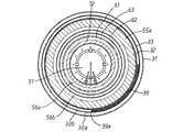
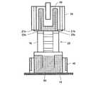
以下、本発明による改質装置の第1の実施の形態を適用した燃料電池システムについて説明する。図1はこの燃料電池システムの概要を示す概要図であり、図2は改質装置を示す拡大断面図である。a) First Embodiment A fuel cell system to which a first embodiment of a reformer according to the present invention is applied will be described below. FIG. 1 is a schematic view showing an outline of the fuel cell system, and FIG. 2 is an enlarged cross-sectional view showing a reformer.
この燃料電池システムは、図1に示すように、燃料電池10と燃料電池10に必要な水素ガスを生成して供給する改質装置20を備えている。燃料電池10の燃料極には、改質装置20から改質ガスが供給され、燃料電池10の空気極には、外部からの空気が供給され、燃料電池10において改質ガス中の水素ガスと空気中の酸素ガスとが反応して発電するようになっている。 As shown in FIG. 1, the fuel cell system includes a
改質装置20は、蒸発部30および一酸化炭素浄化部(以下、CO浄化部という。)40を直接連結することにより一体化してなる外側一体構造体21と、改質部60、冷却部70および一酸化炭素シフト反応部(以下、COシフト部という。)80を直接連結することにより一体化してなる内側一体構造体22とを備えている。外側一体構造体21は基台15に組み付け固定されている。内側一体構造体22は、外側一体構造体の内側に配置され、外側一体構造体21の受け部21a(後述する)上に係止部22a(後述する)を載置させてその接合部分にて1点支持されている。 The
蒸発部30は、供給された水を燃焼ガスによって加熱し水蒸気を生成して後述する改質部70に供給するものであり、主として図2に示すように、筒状(本実施の形態においては円筒状)に形成されている。蒸発部30は、外側底板35を基台15上に当接させて設置固定され、改質部60に対向して空間をおいて同軸に配置されている。 The
この蒸発部30は、外筒31と、この外筒31の内側に改質部60に対向して空間をおいて同軸に配置された内筒32と、両筒31,32の間に配設されて両筒31,32の間の空間を区画する筒状仕切り33とを備えている。外筒31の上端には、環状に形成された天板34の外周端が接続されている。天板34の下面には筒状仕切り33が垂下している。筒状仕切り33と内筒32との間には、図3に示すように、筒状に形成された複数(例えば2つ)のフィン39が両部材33,32に密接して同軸に嵌入されている。このフィン39は、周方向に沿って波状に凹凸が形成されている。各フィン39の間には、筒体39aが嵌入されている。 The
天板34には筒状仕切り33と外筒31との間の環状部位に沿って複数の貫通孔34aが形成され、これら貫通孔34aが水を導出する水導出口である。内筒32は天板34から空間をおいて配置されており、この内筒32の上端と天板34との間によって燃焼ガスを導入する燃焼ガス導入口32aである。天板34の上面には、環状に形成された受け部21aが固定されている。受け部21aは断熱材(例えばセラミック材、セラミックファイバ材)であることが好ましい。これにより、燃焼ガスの熱が冷却部70に逃げていくのを防止することができる。 A plurality of through
外筒31、筒状仕切り33および内筒32の各下端には、それぞれ環状に形成された外側底板35、環状仕切り36および内側底板37の外周端がそれぞれ接続されている。外側底板35の内周端縁には、外筒31、筒状仕切り33および内筒32より短い短筒38が立設されている。短筒38の外周壁面の上下方向中央および上端には、環状仕切り36および内側底板37の内周端がそれぞれ接続されている。外筒31の下部には水を導入する水導入口31aが設けられている。環状仕切り36には燃焼ガスを導出する燃焼ガス導出口36aが外側底板35を貫通して設けられている。 To the lower ends of the
このように構成された蒸発部30においては、水導入口31aから導入された水は、外筒31と筒状仕切り33との間に形成された環状空間、すなわち供給された水が流通(通過)する流水路30aを通って、水導出口(複数の貫通孔34a)から導出する。燃焼ガス導入口32aから導入された燃焼ガスは、筒状仕切り33と内筒32との間に形成された環状空間、すなわち燃焼部50から供給された燃焼ガスが通過する燃焼ガス流路30bを通って、燃焼ガス導出口36aから導出する。そして、筒状仕切り33を介して水と燃焼ガスとの間で熱交換が行われ、水は燃焼ガスによって加熱され、燃焼ガスは降温する。 In the
CO浄化部40は、COシフト部80から供給された改質ガス中の一酸化炭素をさらに低減して燃料電池10に供給するものであり、主として図2に示すように、筒状(本実施の形態においては円筒状)に形成されている。このCO浄化部40は、蒸発部30の天板34に同軸かつ一体的に固定され、冷却部70に対向して空間をおいて同軸に配置されている。 The
CO浄化部40は、蒸発部30の外筒31と同径であり、かつ冷却部70に対向して空間をおいて同軸に配置された外筒41と、この外筒41の内側に同軸に配置された内筒42と、両筒41,42の間に配設されて両筒41,42の間の空間を区画する筒状仕切り43とを備えている。外筒41および内筒42の下端は、蒸発部30の天板34の上面に接続されており、両筒41,42は蒸発部30の天板34に立設されている。外筒41および内筒42の各上端には、環状に形成された天板44の外周端縁および内周端縁がそれぞれ接続されている。筒状仕切り43の上下端には、環状に形成された上下環状仕切り板45,46の各内周端縁が接続されている。上下環状仕切り板45,46の各外周端縁は、外筒41の内周壁面に接続されている。 The
蒸発部30の天板34に設けた貫通孔34aは、蒸発部30においては水(または水蒸気)を導出する水導出口であるが、CO浄化部40においては、水(または水蒸気)を導入する水導入口である。外筒41の下部には下環状仕切り板46の接続部位より上の位置に改質ガスを導出する改質ガス導出口41aが設けられ、外筒41の上部には上環状仕切り板45の接続部位より下の位置に改質ガスを導入する改質ガス導入口41bが設けられている。天板44には水(または水蒸気)を導出する水導出口44aが設けられている。 The through-
このように構成されたCO浄化部40においては、水導入口34aから導入された加熱された水(または水蒸気)は、筒状仕切り43と内筒42との間に形成された空間、すなわち供給された水(または水蒸気)が流通(通過)する流水路40aを通って、水導出口44aから導出する。改質ガス導入口41bから導入された改質ガスは、外筒41と筒状仕切り43との間に形成された空間、すなわちCOシフト部80から供給された改質ガスと空気(酸化空気)との混合ガスが通過する改質ガス流路40bを通って、改質ガス導出口41aから導出する。そして、筒状仕切り43を介して水と改質ガスとの間で熱交換が行われ、水は改質ガスによってさらに加熱され、改質ガスは降温する。また、改質ガス流路40b内においては、導入された混合ガス中の一酸化炭素は、酸素と反応して二酸化炭素になる。この反応は、上下環状仕切り板45,46の間に充填された触媒40c(例えば、RuまたはPt系の触媒)によって促進される。これにより、改質ガスは酸化反応によって一酸化炭素濃度がさらに低減されて(10ppm以下)導出され、燃料電池10の燃料極に供給されるようになっている。 In the
燃焼部50は、改質部60を加熱する燃焼ガスを生成するものであり、主として図2に示すように、蒸発部30の内側に同軸に空間をおいて配置されている。この燃焼部50は、バーナ本体51とバーナ燃焼部52とから構成されている。バーナ本体51は、上下方向中央にフランジ51aが形成されている。このフランジ51aが、蒸発部30の内側底板37の内周端から内側に向けて凸設した環状フランジ37aに取り付け固定されている。これにより、バーナ本体51の上半分が蒸発部30の内側に挿入されて取り付けられる。バーナ本体51の下部には燃焼用燃料、燃焼空気およびオフガスを導入するガス導入口51bが設けられ、バーナ本体51の上部には導入された燃焼用燃料またはオフガスに着火する着火手段である電極51cが設けられている。バーナ燃焼部52は、筒状に形成されており、バーナ本体51の上部に外嵌され、蒸発部30に対向して配置されている。バーナ燃焼部52内において、着火手段によって着火された燃焼用燃料またはオフガスが燃焼する。このバーナ燃焼部52は、断熱材(例えば、セラミック材、セラミックファイバ材)で形成されている。 The
このように構成された燃焼部50においては、ガス導入口51bから導入された燃焼用燃料またはオフガスが燃焼されて、その燃焼ガスがバーナ燃焼部52の開口端から導出される。そして、この燃焼ガスは、バーナ燃焼部52と改質部60の筒部の内壁面との間に形成された環状流路56aと、改質部60の筒部の外壁面と断熱部材55との間に形成されて環状流路56aの下部と連通する環状流路56bとを通って蒸発部30の燃焼ガス流路30bに導出される。 In the
なお、蒸発部30と改質部60との間には蒸発部30の内壁面、すなわち蒸発部30の内筒32の内周壁面および内側底板37の上面を覆うように断熱部材55が配置されている。断熱部材55は、筒体55aと、筒体55aの下端に外周端が接続された環状底板55bとが一体形成されたものである。環状底板55bの内周端はバーナ燃焼部52の下端に気密に密接している。 A
改質部60は、外部から供給された燃料と水蒸気との混合ガスから改質ガスを生成して導出するものであり、主として図2に示すように、有底円筒状に形成されている。この改質部60は、燃焼部50のバーナ燃焼部52と断熱部材55の筒体55aとの間の環状空間に改質部60の筒部が挿入され、蒸発部30に取り囲まれるように配置されている。この改質部60は、後述する冷却部70の環状マニホールド73の底板73bに一体的に固定されている。 The reforming
改質部60の筒部は、外筒61と、この外筒61の内側に同軸に配置された内筒62と、両筒61,62の間に配設されて両筒61,62の間の空間を仕切る筒状の中仕切り63とを備えている。外筒61および中仕切り63は、冷却部70の環状マニホールド73の底板73bから垂下している。冷却部70の底板73bに形成された貫通孔73b1は、燃料と水蒸気との混合ガスを導入する混合ガス導入口である。外筒61の下端には環状に形成された底板64の外周端が接続されている。底板64の内周端縁には、内筒62が立設されている。内筒62の上端開口は内側天板65によって覆蓋されている。中仕切り63の下端は底板64から空間をおいて配置されている。外筒61と中仕切り63との間には環状押さえ板66が嵌着され、内筒62には中央に開口67aが形成されている環状仕切り板67が嵌着されている。開口67aはフィルタ68で覆われている。開口67aは、改質ガスを導出する改質ガス導出口である。 The cylinder portion of the reforming
環状押さえ板66と環状仕切り板67との間の改質部60内には、触媒60a(例えば、RuまたはNi系の触媒)が充填されており、混合ガス導入口73b1から導入された燃料と水蒸気との混合ガスが触媒60aによって反応し改質されて水素ガスと一酸化炭素ガスが生成されている(いわゆる水蒸気改質反応)。これと同時に、水蒸気改質反応にて生成された一酸化炭素と水蒸気が反応して水素ガスと二酸化炭素とに変成するいわゆる一酸化炭素シフト反応が生じている。これら生成されたガス(いわゆる改質ガス)は改質ガス導出口67aを通って冷却部70に導出される。 The reforming
冷却部70は、改質部60から導出された改質ガスを燃料と水蒸気との混合ガスによって降温して導出するものであり、主として図2に示すように、改質部60と同軸に固定されている。冷却部70は、蒸発部30に設けた受け部21aに係止部22aとしての環状マニホールド73の下部周縁が載置されて支持されている。冷却部70は、CO浄化部40の内部に空間をおいて対向させて配置され、すなわちCO浄化部40に取り囲まれるように配置されている。 The cooling
冷却部70は、円筒ハウジング71を備えている。円筒ハウジング71の上端および下端には、それぞれ環状マニホールド72,73の外周端が接続されている。環状マニホールド72は、それぞれ環状に形成された天板72aおよび底板72bと、天板72aおよび底板72bの外周端に上下端が接続された外筒72cと、天板72aおよび底板72bの内周端に上下端が接続された内筒72dとから構成されている。天板72aには、燃料と水蒸気との混合ガスを導入する混合ガス導入口72a1が設けられている。底板72bには、後述するマニホールド76と連通する貫通孔72b1が設けられている。環状マニホールド73も、環状マニホールド72と同様に、それぞれ環状に形成された天板73aおよび底板73b、外筒73cおよび内筒73dから構成されている。天板73aには、後述するマニホールド75と連通する貫通孔73a1が設けられている。底板73bには、改質部60の外筒61と中仕切り63との間の環状部位に沿って複数の貫通孔73b1が形成されている。 The cooling
両環状マニホールド72,73の開口72e,73eの各周縁には断面方形状の内筒74の上下端が接続されている。内筒74の互いに対向する一対の側壁の外壁面には、縦長の箱状に形成された一対のマニホールド75,76が設けられている。両マニホールド75,76の上下端は環状マニホールド72,73にそれぞれ密着固定されている。内筒74内には、両マニホールド75,76を連通する複数の熱交換パイプ77が設けられている。熱交換パイプ77の外周には表面積を大きくして熱伝達効果を向上するためのフィン77aが設けられている。 The upper and lower ends of the
このように構成された冷却部70においては、混合ガス導入口72a1から導入された燃料と水蒸気の混合ガスは、環状マニホールド72、貫通孔72b1、マニホールド76、熱交換パイプ77、マニホールド75、貫通孔73a1、環状マニホールド73、および貫通孔73b1を通って改質部60に導出される。一方、改質ガス導入口である環状マニホールド73の開口73eから導入された改質ガスは、内筒74および環状マニホールド72の開口72eを通ってCOシフト部80に導出される。そして、熱交換パイプ77を介して混合ガスと改質ガスとの間で熱交換が行われ、混合ガスは改質ガスによって加熱され、改質ガスは降温する。 In the
COシフト部80は、冷却部70から供給された改質ガス中の一酸化炭素を低減するものであり、主として図2に示すように、冷却部70上に同軸に固定されている。COシフト部80は、外筒81と、外筒81と同軸に配置された内筒82を備えている。外筒81および内筒82の各下端縁には環状に形成された底板83の外周縁および内周縁が一体的に取り付け固定されている。外筒81の上端縁には円板状に形成された天板84の外周縁が一体的に取り付け固定されている。天板84と内筒82の上端との間には隙間が形成されている。外筒81の外周下部には改質ガスが導出される改質ガス導出口81aが設けられている。内筒82の下方への延長部82aは、冷却部70の環状マニホールド72の天板72a上に一体的に取り付け固定されている。延長部82aは冷却部70から導出された改質ガスを導入する改質ガス導入口である。 The
COシフト部80の内筒82の下部には、円板状に形成されて多数の孔を有する第1支持部材85が取り付けられ、この第1支持部材85により内筒82に充填された触媒80a(例えば、Cu、Zn系の触媒)が支持されている。また、外筒81と内筒82の間の下方にも底板83から距離を置いて環状円板に形成されて多数の孔を有する第2支持部材86が取り付けられ、この第2支持部材86により外筒81と内筒82との間に充填された触媒80aが支持されている。 A
このように構成されたCOシフト部80においては、改質ガス導入口82aから導入された改質ガスは、内筒82、および内筒82と外筒81との間の空間を通って改質ガス導出口81aから導出する。このとき、供給された改質ガスに含まれる一酸化炭素と水蒸気が触媒80aにより反応して水素ガスと二酸化炭素ガスとに変成するいわゆる一酸化炭素シフト反応が生じている。 In the
上述のように構成された改質装置の定常運転時には、図1に示すように、蒸発部30に供給された水は、流水路30aにおいて燃焼ガス流路30bを流れる燃焼ガスによって加熱され、CO浄化部40の流水路40aに導出される。CO浄化部40の流水路40aに供給された水(または水蒸気)は、この流水路40aにおいてCOシフト部80から供給されて改質ガス流路40bを流れる改質ガスによって加熱され、冷却部70のマニホールド76に導出される。このとき、水(または水蒸気)には燃料が混合され、冷却部70のマニホールド76には、これらが混合された混合ガスが導出されている。 During steady operation of the reformer configured as described above, as shown in FIG. 1, the water supplied to the
冷却部70においては、導入された混合ガスが上述したように環状マニホールド73へ到達する間に、改質部60から供給されて内筒74内を流れる改質ガスによって加熱され完全に気体化されて、改質部60に導出される。改質部60においては、導入された混合ガスが改質されて水素ガスと一酸化炭素ガスが生成されている。これと同時に、水蒸気改質反応にて生成された一酸化炭素と水蒸気が反応して水素ガスと二酸化炭素とに変成するいわゆる一酸化炭素シフト反応が生じている。これら生成されたガス(いわゆる改質ガス)は冷却部70の内筒74に導出される。冷却部70の内筒74内においては、改質ガスが内筒74を通過する間に降温され、COシフト部80に導出される。 In the
そして、COシフト部80においては、冷却部70から供給された改質ガスがその中に含まれる一酸化炭素を低減されてCO浄化部40の改質ガス流路40bに導出される。このとき、改質ガスには酸化反応用空気が混合され、CO浄化部40の改質ガス流路40bには、これらが混合された混合ガスが導出されている。CO浄化部40の改質ガス流路40bにおいては、混合ガスは酸化反応によって一酸化炭素濃度がさらに低減されて導出され、燃料電池10の燃料極に供給されている。 In the
なお、定常運転状態の改質装置20においては、燃焼部50の温度は約1000℃であり一番高く、改質部60は500〜700℃であり、冷却部70は200〜600℃であり、COシフト部80は200〜300℃であり、CO浄化部40は100〜200℃であり、蒸発部30は約100℃である。 In the
また、CO浄化部40と燃料電池10の間には切替え装置90が設けられており、定常運転時にはCO浄化部40を燃料電池10に連通し、起動運転時には一酸化炭素濃度が高い改質ガスを燃料電池10に供給しないようにするためCO浄化部40を燃焼部50のバーナ本体51に連通するように切り替えられている。これにより、起動運転時には、外部からの燃焼用燃料またはCO浄化部40から導出された改質ガスの少なくともどちらか一方がバーナ本体51に供給されて燃焼され、定常運転時には、燃料電池10で未使用の水素ガス(オフガス)がバーナ本体51に供給されて燃焼される。 Further, a
上述した説明から理解できるように、この実施の形態においては、改質装置20の定常運転時に高温となる改質部60および冷却部70が、これらの構成要素より低温となる蒸発部30およびCO浄化部40によってそれぞれ取り囲まれるので、改質部60および冷却部70からの放熱は、蒸発部30およびCO浄化部40によって吸収される。これにより、従来系外に放出されていた熱を蒸発部30およびCO浄化部40にて利用し、改質部60および冷却部70からの放熱を系外に放出するのを防止するので、改質装置20の熱効率を向上させることができる。 As can be understood from the above description, in this embodiment, the reforming
また、蒸発部30およびCO浄化部40は、改質部60および冷却部70から空間をおいて配置されているので、高温となる構成要素と低温となる構成要素を離して配置することにより、両要素間での熱の引っ張り合いを防止し、熱効率の低下を防止することができる。さらに、熱膨張率の違いに起因する破損も防止することができる。 Further, since the
また、改質部60、冷却部70およびCOシフト部80をこの順番に直列に並べて互いの間に接続管を介装しないで直接連結することにより、改質部60、冷却部70およびCOシフト部80を一体化し内側一体構造体22を形成したため、この内側一体構造体22には外部に露呈する接続管がなくなるので、接続管からの放熱をなくして改質装置20の熱効率を向上させることができる。 Further, the reforming
また、蒸発部30およびCO浄化部40をその間に接続管を介装しないで直接連結することにより、蒸発部30およびCO浄化部40を一体化して外側一体構造体21を形成したため、この外側一体構造体21には外部に露呈する接続管がなくなるので、接続管からの放熱をなくして改質装置20の熱効率を向上させることができる。 In addition, since the
また、基台15に組み付け固定された外側一体構造体21に設けた受け部21a上に内側一体構造体22に設けた係止部22aを載置してその接合部分にて一点支持することにより、外側一体構造体21に内側一体構造体22を組み付けたため、内側一体構造体22は外側一体構造体21に固定されておらず載置されているだけなので、内外側両一体構造体21,22が互いに異なる膨張率によってそれぞれ上下方向に膨張しても、熱膨張率差に起因する応力集中の発生を防止して改質装置20の損傷を防止することにより、改質装置20の耐久性を向上させることができる。 In addition, by placing a locking
また、蒸発部30は、隣接する内外二つの環状流路30b,30aを備えた筒状に形成され、内側環状流路30aに燃焼ガスを流通させ、外側環状流路30bに水を流通させるので、改質部60および冷却部70からの放熱を系外に放出するのを防止するのに加えて、内側環状流路30aを流通する燃焼ガスからの熱も確実に吸収する。これにより、改質装置20の熱効率を向上させることができる。 Further, the
また、CO浄化部40は、隣接する内外二つの環状流路40a,40bを備えた筒状に形成され、内側環状流路40aに水または水蒸気を流通させ、外側環状流路40bに改質ガスを流通させるので、改質部60および冷却部70からの放熱を系外に放出するのを防止するのに加えて、内側および外側にそれぞれ改質ガスおよび水(または水蒸気)を流した場合、冷却部70の高熱によってCO浄化部40の触媒40cが活性温度より上昇され、蒸発部30で昇温された水(または水蒸気)が外気によって降温されることによる、改質装置20で発生する熱エネルギーの無駄をなくすことができる。すなわち、内側環状流路40aを流れる水が改質部60および冷却部70からの放熱を吸収して外側環状流路40bを流れる改質ガスを再加熱されるのを防止する。したがって、改質装置20の熱効率を向上させることができる。 The
なお、上述した実施の形態においては、改質部60および冷却部70をそれぞれ蒸発部30およびCO浄化部40で取り囲むようにしたが、蒸発部30とCO浄化部40を入れ替えて、改質部60および冷却部70をそれぞれCO浄化部40および蒸発部30で取り囲むようにしてもよい。また、改質部60および冷却部70を軸方向に延ばした蒸発部30(またはCO浄化部40)で取り囲み、COシフト部80をCO浄化部40(または蒸発部30)で取り囲むようにしてもよい。 In the above-described embodiment, the reforming
また、上述した実施の形態においては、受け部21aを蒸発部30に設けるとともに係止部22aを冷却部70に設けるようにしたが、これに代えて、受け部21aを外側一体構造体21の他の構成要素(すなわちCO浄化部40)に設けるとともに、係止部22aをその構成要素に対向して位置する内側一体構造体22の構成要素に設けるようにしてもよい。 In the above-described embodiment, the receiving
b)第2の実施の形態
以下、本発明による改質装置の第2の実施の形態を適用した燃料電池システムについて説明する。図4はこの燃料電池システムの概要を示す概要図である。第1の実施の形態と同一の構成部分については同一符号を付してその説明を省略し、異なる部分について説明する。b) Second Embodiment Hereinafter, a fuel cell system to which a second embodiment of the reformer according to the present invention is applied will be described. FIG. 4 is a schematic diagram showing an outline of this fuel cell system. The same components as those of the first embodiment are denoted by the same reference numerals, description thereof is omitted, and different portions are described.
上述した第1の実施の形態においては、蒸発部30およびCO浄化部40を一体化して外側一体構造体21を形成し、基台15に組み付け固定された外側一体構造体21に設けた受け部21a上に内側一体構造体22に設けた係止部22aを載置してその接合部分にて一点支持することにより、外側一体構造体21に内側一体構造体22を組み付けるようにしたが、これに代えて、蒸発部30およびCO浄化部40を一体構造体とせずに互いに別体とし、基台15に組み付け固定された蒸発部30(またはCO浄化部40)に設けた受け部21a上に内側一体構造体22に設けた係止部22aを載置してその接合部分にて一点支持することにより、蒸発部30(またはCO浄化部40)に内側一体構造体22を組み付けるようにしてもよい。なお、CO浄化部40はCOシフト部80(または冷却部70)に直接(または空間をおいて)固定されている。また、第2〜第5の実施の形態においては、改質装置20の構成要素は、水(または水蒸気)、水(または水蒸気)と燃料の混合ガス、改質ガスおよび燃焼ガスの流れが第1の実施の形態と同様となるように適宜接続されている。 In the first embodiment described above, the
これによれば、内側一体構造体22は蒸発部30(またはCO浄化部40)に固定されておらず載置されているだけなので、蒸発部30(またはCO浄化部40)と内側一体構造体22とが互いに異なる膨張率によってそれぞれ上下方向に膨張しても、熱膨張率差に起因する応力集中の発生を防止して改質装置20の損傷を防止することにより、改質装置20の耐久性を向上させることができる。 According to this, since the inner
c)第3の実施の形態
以下、本発明による改質装置の第3の実施の形態を適用した燃料電池システムについて説明する。図5はこの燃料電池システムの概要を示す概要図である。第1の実施の形態と同一の構成部分については同一符号を付してその説明を省略し、異なる部分について説明する。c) Third Embodiment Hereinafter, a fuel cell system to which a third embodiment of a reformer according to the present invention is applied will be described. FIG. 5 is a schematic diagram showing an outline of the fuel cell system. The same components as those of the first embodiment are denoted by the same reference numerals, description thereof is omitted, and different portions are described.
上述した第1の実施の形態においては、蒸発部30およびCO浄化部40を一体化して外側一体構造体21を形成するとともに、改質部60、冷却部70およびCOシフト部80を一体化して内側一体構造体22を形成し、基台15に組み付け固定された外側一体構造体21に設けた受け部21a上に内側一体構造体22に設けた係止部22aを載置してその接合部分にて一点支持することにより、外側一体構造体21に内側一体構造体22を組み付けるようにしたが、これに代えて、基台15に組み付け固定された内側一体構造体22に設けた受け部22b上に外側一体構造体21に設けた係止部21bを載置してその接合部分にて一点支持することにより、内側一体構造体22に外側一体構造体21を組み付けるようにしてもよい。この場合、外側一体構造体21および内側一体構造体22はそれらの配列順が第1の実施の形態と上下逆となっている。 In the first embodiment described above, the
これによれば、外側一体構造体21は内側一体構造体22に固定されておらず載置されているだけなので、内外側両一体構造体21,22が互いに異なる膨張率によってそれぞれ上下方向に膨張しても、熱膨張率差に起因する応力集中の発生を防止して改質装置20の損傷を防止することにより、改質装置20の耐久性を向上させることができる。 According to this, since the outer
d)第4の実施の形態
以下、本発明による改質装置の第4の実施の形態を適用した燃料電池システムについて説明する。図6はこの燃料電池システムの概要を示す概要図である。第3の実施の形態と同一の構成部分については同一符号を付してその説明を省略し、異なる部分について説明する。d) Fourth Embodiment Hereinafter, a fuel cell system to which a fourth embodiment of a reformer according to the present invention is applied will be described. FIG. 6 is a schematic diagram showing an outline of the fuel cell system. The same components as those in the third embodiment are denoted by the same reference numerals, description thereof is omitted, and different portions are described.
上述した第3の実施の形態においては、蒸発部30およびCO浄化部40を一体化して外側一体構造体21を形成し、基台15に組み付け固定された内側一体構造体22に設けた受け部22b上に外側一体構造体21に設けた係止部21bを載置してその接合部分にて一点支持することにより、内側一体構造体22に
外側一体構造体21を組み付けるようにしたが、これに代えて、基台15に組み付け固定された内側一体構造体22に設けた受け部22b上に蒸発部30(またはCO浄化部40)に設けた係止部21bを載置してその接合部分にて一点支持することにより、内側一体構造体22に蒸発部30(またはCO浄化部40)を組み付けるようにしてもよい。なお、CO浄化部40はCOシフト部80(または冷却部70)に直接(または空間をおいて)固定されている。In the above-described third embodiment, the
これによれば、蒸発部30(またはCO浄化部40)は内側一体構造体22に固定されておらず載置されているだけなので、蒸発部30(またはCO浄化部40)と内側一体構造体22とが互いに異なる膨張率によってそれぞれ上下方向に膨張しても、熱膨張率差に起因する応力集中の発生を防止して改質装置20の損傷を防止することにより、改質装置20の耐久性を向上させることができる。 According to this, since the evaporation unit 30 (or the CO purification unit 40) is not fixed to the inner
e)第5の実施の形態
以下、本発明による改質装置の第5の実施の形態を適用した燃料電池システムについて説明する。図7はこの燃料電池システムの概要を示す概要図である。第1の実施の形態と同一の構成部分については同一符号を付してその説明を省略し、異なる部分について説明する。e) Fifth Embodiment Hereinafter, a fuel cell system to which a fifth embodiment of a reformer according to the present invention is applied will be described. FIG. 7 is a schematic diagram showing an outline of the fuel cell system. The same components as those of the first embodiment are denoted by the same reference numerals, description thereof is omitted, and different portions are described.
上述した第1の実施の形態においては、改質部60、冷却部70およびCOシフト部80を直列して一体化して内側一体構造体22を形成し、蒸発部30およびCO浄化部40はこの内側一体構造体22を取り囲んでいたが、これに代えて、図7に示すように、冷却部70およびCOシフト部80を互いに隣り合うように水平方向に並べて配置して一体化したものに改質部60を連結した一体構造体25を形成し、CO浄化部40(または蒸発部30)は冷却部70およびCOシフト部80を取り囲むようにしてもよい。なお、蒸発部30(またはCO浄化部40)は改質部60に直接(または空間をおいて)固定されている。これによれば、改質部60、冷却部70およびCOシフト部80を上下方向に重ねて直列に連結していたものと比べて、改質装置20の上下方向を短くすることができ、装置自体を小型化することができる。 In the first embodiment described above, the reforming
f)第6の実施の形態
以下、本発明による改質装置の第6の実施の形態を適用した燃料電池システムについて説明する。図8はこの燃料電池システムの概要を示す概要図である。第5の実施の形態と同一の構成部分については同一符号を付してその説明を省略し、異なる部分について説明する。f) Sixth Embodiment Hereinafter, a fuel cell system to which a sixth embodiment of a reformer according to the present invention is applied will be described. FIG. 8 is a schematic diagram showing an outline of this fuel cell system. The same components as those in the fifth embodiment are denoted by the same reference numerals, description thereof is omitted, and different portions are described.
上述した第5の実施の形態においては、冷却部70およびCOシフト部80を互いに隣り合うように水平方向に並べて配置するようにしたが、これに代えて、図8に示すように、COシフト部80を円筒状に形成し、このCOシフト部80を空間をおいて冷却部70を取り囲むように同軸に配置し、CO浄化部40(または蒸発部30)はCOシフト部80をさらに取り囲むように配置してもよい。なお、蒸発部30(またはCO浄化部40)は改質部60に直接(または空間をおいて)固定されている。これによれば、冷却部70の放熱をCOシフト部80で利用し、COシフト部80の放熱を蒸発部30(またはCO浄化部40)で利用するので、改質装置20の熱効率をさらに向上させることができる。 In the fifth embodiment described above, the cooling
10…燃料電池、15…基台、20…改質装置、21…外側一体構造体、21a,22b…受け部、21b,22a…係止部、22…内側一体構造体、30…蒸発部、30a…流水路、30b…燃焼ガス流路、31…外筒、31a…水導入口、32…内筒、32a…燃焼ガス導入口、33…筒状仕切り、34…天板、34a…貫通孔(水導出口)、35…外側底板、36…環状仕切り、36a…燃焼ガス導出口、37…内側底板、38…短筒、39…波状フィン、40…一酸化炭素浄化部(CO浄化部)、40a…流水路、40b…改質ガス流路、40c…触媒、41…外筒、41a…改質ガス導出口、41b…改質ガス導入口、42…内筒、43…筒状仕切り、44…天板、44a…水導出口、45,46…上下環状仕切り板、50…燃焼部、51…バーナ本体、51b…ガス導入口、52…バーナ燃焼部、55…断熱部材、56a,56b…環状流路、60…改質部、60a…触媒、61…外筒、62…内筒、63…中仕切り、64…底板、65…内側天板、66…環状押さえ板、67…環状仕切り板、67a…開口、70…冷却部、71…円筒ハウジング、72,73…環状マニホールド、74…内筒、75,76…マニホールド、77…熱交換パイプ、77a…フィン、80…一酸化炭素シフト反応部(COシフト部)、80a…触媒、81…外筒、81a…改質ガス導出口、82…内筒、82a…延長部(改質ガス導入口)、83…底板、84…天板、90…切替え装置。 DESCRIPTION OF
Claims (7)
Translated fromJapanese前記一酸化炭素浄化部および蒸発部は筒状に形成され、該一酸化炭素浄化部および蒸発部のいずれか一方は、前記改質部を取り囲むように配置されるとともに、他方は、前記冷却部および一酸化炭素シフト反応部の少なくとも何れか一方を取り囲むように配置され、
前記一酸化炭素浄化部および蒸発部をその間に接続管を介装しないで直接連結することにより、前記一酸化炭素浄化部および蒸発部を一体化して外側一体構造体を形成したことを特徴とする改質装置。A reforming section that generates and derives a reformed gas from a mixed gas of fuel and water vapor supplied from the outside, a combustion section that generates a combustion gas that heats the reforming section, and the combustion of the supplied water An evaporating unit that is heated by gas to generate the water vapor and supplies the steam to the reforming unit; a cooling unit that cools and derives the reformed gas derived from the reforming unit using the mixed gas; and the cooling unit A carbon monoxide shift reaction unit for reducing carbon monoxide in the reformed gas supplied from the fuel, and a fuel by further reducing carbon monoxide in the reformed gas supplied from the carbon monoxide shift reaction unit In the reformer configured with the carbon monoxide purification unit that supplies the battery,
The carbon monoxide purification unit and the evaporation unit are formed in a cylindrical shape, and one of the carbon monoxide purification unit and the evaporation unit is disposed so as to surround the reforming unit, and the other is the cooling unit. And at least one of the carbon monoxide shift reaction part,
The carbon monoxide purification part and the evaporation part are directly connected without interposing a connecting pipe therebetween, so that the carbon monoxide purification part and the evaporation part are integrated to form an outer integrated structure. Reformer.
前記一酸化炭素浄化部および蒸発部は筒状に形成され、該一酸化炭素浄化部および蒸発部のいずれか一方は、前記改質部を取り囲むように配置されるとともに、他方は、前記冷却部および一酸化炭素シフト反応部の少なくとも何れか一方を取り囲むように配置され、
前記改質部、冷却部および一酸化炭素シフト反応部をこの順番に直列に並べて互いの間に接続管を介装しないで直接連結することにより、前記改質部、冷却部および一酸化炭素シフト反応部を一体化し内側一体構造体を形成し、
基台に組み付け固定された前記一酸化炭素浄化部または蒸発部に設けた受け部上に前記内側一体構造体に設けた係止部を載置してその接合部分にて一点支持することにより、前記一酸化炭素浄化部または蒸発部に前記内側一体構造体を組み付けたことを特徴とする改質装置。A reforming section that generates and derives a reformed gas from a mixed gas of fuel and water vapor supplied from the outside, a combustion section that generates a combustion gas that heats the reforming section, and the combustion of the supplied water An evaporating unit that is heated by gas to generate the water vapor and supplies the steam to the reforming unit; a cooling unit that cools and derives the reformed gas derived from the reforming unit using the mixed gas; and the cooling unit A carbon monoxide shift reaction unit for reducing carbon monoxide in the reformed gas supplied from the fuel, and a fuel by further reducing carbon monoxide in the reformed gas supplied from the carbon monoxide shift reaction unit In the reformer configured with the carbon monoxide purification unit that supplies the battery,
The carbon monoxide purification unit and the evaporation unit are formed in a cylindrical shape, and one of the carbon monoxide purification unit and the evaporation unit is disposed so as to surround the reforming unit, and the other is the cooling unit. And at least one of the carbon monoxide shift reaction part,
The reforming unit, the cooling unit, and the carbon monoxide shift reaction unit are arranged in series in this order and directly connected without interposing a connecting pipe therebetween, thereby the reforming unit, the cooling unit, and the carbon monoxide shift. The reaction part is integrated to form an inner integrated structure,
By placing a locking part provided in the inner integrated structure on a receiving part provided in the carbon monoxide purification part or evaporation part fixedly assembled to a base, and supporting it at one point at its joint part, A reformer characterized in that theinner integrated structure is assembled to the carbon monoxide purification section or the evaporation section .
前記一酸化炭素浄化部および蒸発部は筒状に形成され、該一酸化炭素浄化部および蒸発部のいずれか一方は、前記改質部を取り囲むように配置されるとともに、他方は、前記冷却部および一酸化炭素シフト反応部の少なくとも何れか一方を取り囲むように配置され、
前記改質部、冷却部および一酸化炭素シフト反応部をこの順番に直列に並べて互いの間に接続管を介装しないで直接連結することにより、前記改質部、冷却部および一酸化炭素シフト反応部を一体化し内側一体構造体を形成し、
基台に組み付け固定された前記内側一体構造体に設けた受け部上に前記一酸化炭素浄化部または蒸発部に設けた係止部を載置してその接合部分にて一点支持することにより、前記内側一体構造体に前記一酸化炭素浄化部または蒸発部を組み付けたことを特徴とする改質装置。A reforming section that generates and derives a reformed gas from a mixed gas of fuel and water vapor supplied from the outside, a combustion section that generates a combustion gas that heats the reforming section, and the combustion of the supplied water An evaporating unit that is heated by gas to generate the water vapor and supplies the steam to the reforming unit; a cooling unit that cools and derives the reformed gas derived from the reforming unit using the mixed gas; and the cooling unit A carbon monoxide shift reaction unit for reducing carbon monoxide in the reformed gas supplied from the fuel, and a fuel by further reducing carbon monoxide in the reformed gas supplied from the carbon monoxide shift reaction unit In the reformer configured with the carbon monoxide purification unit that supplies the battery,
The carbon monoxide purification unit and the evaporation unit are formed in a cylindrical shape, and one of the carbon monoxide purification unit and the evaporation unit is disposed so as to surround the reforming unit, and the other is the cooling unit. And at least one of the carbon monoxide shift reaction part,
The reforming unit, the cooling unit, and the carbon monoxide shift reaction unit are arranged in series in this order and directly connected without interposing a connecting pipe therebetween, thereby the reforming unit, the cooling unit, and the carbon monoxide shift. The reaction part is integrated to form an inner integrated structure,
By mounting a locking part provided in the carbon monoxide purification part or the evaporation part on the receiving part provided in the inner integrated structure fixed to the base, and supporting it at one point at the joint part, A reforming apparatus, wherein the carbon monoxide purification section or the evaporation section is assembled to the inner integrated structure .
前記一酸化炭素浄化部および蒸発部は筒状に形成され、該一酸化炭素浄化部および蒸発部のいずれか一方は、前記改質部を取り囲むように配置されるとともに、他方は、互いに隣り合うように水平方向に並べて配置された前記冷却部および一酸化炭素シフト反応部を取り囲むように配置されることを特徴とする改質装置。
A reforming section that generates and derives a reformed gas from a mixed gas of fuel and water vapor supplied from the outside, a combustion section that generates a combustion gas that heats the reforming section, and the combustion of the supplied water An evaporating unit that is heated by gas to generate the water vapor and supplies the steam to the reforming unit; a cooling unit that cools and derives the reformed gas derived from the reforming unit using the mixed gas; and the cooling unit A carbon monoxide shift reaction unit for reducing carbon monoxide in the reformed gas supplied from the fuel, and a fuel by further reducing carbon monoxide in the reformed gas supplied from the carbon monoxide shift reaction unit In the reformer configured with the carbon monoxide purification unit that supplies the battery,
The carbon monoxide purifier unit and the evaporation unit is formed in a tubular shape, is one of the carbon monoxide purifier and the evaporation portion, while being arranged so as to surround the reforming unit and theother, toeach other physician A reformer characterizedby being disposed so as to surround the cooling section and the carbon monoxide shift reaction section that are arranged side by side in a horizontal direction.
前記一酸化炭素浄化部および蒸発部は筒状に形成され、該一酸化炭素浄化部および蒸発部のいずれか一方は、前記改質部を取り囲むように配置されるとともに、他方は、前記冷却部を空間をおいて取り囲んだ前記一酸化炭素シフト反応部をさらに取り囲むように配置されることを特徴とする改質装置。
A reforming section that generates and derives a reformed gas from a mixed gas of fuel and water vapor supplied from the outside, a combustion section that generates a combustion gas that heats the reforming section, and the combustion of the supplied water An evaporating unit that is heated by gas to generate the water vapor and supplies the steam to the reforming unit; a cooling unit that cools and derives the reformed gas derived from the reforming unit using the mixed gas; and the cooling unit A carbon monoxide shift reaction unit for reducing carbon monoxide in the reformed gas supplied from the fuel, and a fuel by further reducing carbon monoxide in the reformed gas supplied from the carbon monoxide shift reaction unit In the reformer configured with the carbon monoxide purification unit that supplies the battery,
The carbon monoxide purification unit and the evaporation unit are formed in a cylindrical shape, and one of the carbon monoxide purification unit and the evaporation unit is disposed so as to surround the reforming unit, and the other is the cooling unit. Isdisposed so as to further surround the carbon monoxide shift reaction portion surrounded by a space.
Priority Applications (1)
| Application Number | Priority Date | Filing Date | Title |
|---|---|---|---|
| JP2003340805AJP4316975B2 (en) | 2003-09-30 | 2003-09-30 | Reformer |
Applications Claiming Priority (1)
| Application Number | Priority Date | Filing Date | Title |
|---|---|---|---|
| JP2003340805AJP4316975B2 (en) | 2003-09-30 | 2003-09-30 | Reformer |
Publications (2)
| Publication Number | Publication Date |
|---|---|
| JP2005104776A JP2005104776A (en) | 2005-04-21 |
| JP4316975B2true JP4316975B2 (en) | 2009-08-19 |
Family
ID=34535593
Family Applications (1)
| Application Number | Title | Priority Date | Filing Date |
|---|---|---|---|
| JP2003340805AExpired - Fee RelatedJP4316975B2 (en) | 2003-09-30 | 2003-09-30 | Reformer |
Country Status (1)
| Country | Link |
|---|---|
| JP (1) | JP4316975B2 (en) |
Families Citing this family (4)
| Publication number | Priority date | Publication date | Assignee | Title |
|---|---|---|---|---|
| JP4009285B2 (en) | 2004-11-24 | 2007-11-14 | アイシン精機株式会社 | Reformer |
| TWI438957B (en)* | 2011-09-22 | 2014-05-21 | Atomic Energy Council | Combustion reformer for fuel cell power generating system |
| WO2014002470A1 (en) | 2012-06-25 | 2014-01-03 | パナソニック株式会社 | Fuel treatment device |
| WO2014002472A1 (en) | 2012-06-25 | 2014-01-03 | パナソニック株式会社 | Fuel processing device |
- 2003
- 2003-09-30JPJP2003340805Apatent/JP4316975B2/ennot_activeExpired - Fee Related
Also Published As
| Publication number | Publication date |
|---|---|
| JP2005104776A (en) | 2005-04-21 |
Similar Documents
| Publication | Publication Date | Title |
|---|---|---|
| US4504447A (en) | Slab reformer | |
| US4430304A (en) | Slab reformer | |
| JP5693854B2 (en) | Fuel reformer for polymer electrolyte fuel cell | |
| JP4736298B2 (en) | Partial oxidation reformer | |
| JP5185493B2 (en) | Fuel conversion reactor | |
| US5811065A (en) | Burner exhaust gas collection assembly for a catalytic reformer | |
| JP2015180602A (en) | Hydrogen generation assembly and hydrogen purification device | |
| JP4009285B2 (en) | Reformer | |
| JP2008120634A (en) | Reformer, reforming unit and fuel cell system | |
| JP4316975B2 (en) | Reformer | |
| CA2521698A1 (en) | Selective oxidation reactor | |
| JP2005514303A (en) | Integration of the fuel processor module into a general housing | |
| WO2011081094A1 (en) | Reforming unit and fuel cell system | |
| JP4268005B2 (en) | Reformer | |
| JP5534901B2 (en) | Hydrogen production apparatus and fuel cell system | |
| JP2005104777A (en) | Reformer | |
| JP2005108651A (en) | Reformer | |
| JP4369163B2 (en) | Reformer | |
| CN101573290B (en) | Reformer, reforming unit, and fuel cell system | |
| JP2005314210A (en) | Reformer | |
| JP4450754B2 (en) | Fuel reformer | |
| JP2025081030A (en) | Solid oxide cell system | |
| JP2024049875A (en) | Fuel Cell Module | |
| JP2008189502A (en) | Reforming unit and fuel cell system | |
| JP2008189506A (en) | Reforming unit and fuel cell system |
Legal Events
| Date | Code | Title | Description |
|---|---|---|---|
| A621 | Written request for application examination | Free format text:JAPANESE INTERMEDIATE CODE: A621 Effective date:20060531 | |
| A977 | Report on retrieval | Free format text:JAPANESE INTERMEDIATE CODE: A971007 Effective date:20080905 | |
| A131 | Notification of reasons for refusal | Free format text:JAPANESE INTERMEDIATE CODE: A131 Effective date:20081104 | |
| A521 | Written amendment | Free format text:JAPANESE INTERMEDIATE CODE: A523 Effective date:20081225 | |
| A131 | Notification of reasons for refusal | Free format text:JAPANESE INTERMEDIATE CODE: A131 Effective date:20090203 | |
| A521 | Written amendment | Free format text:JAPANESE INTERMEDIATE CODE: A523 Effective date:20090402 | |
| TRDD | Decision of grant or rejection written | ||
| A01 | Written decision to grant a patent or to grant a registration (utility model) | Free format text:JAPANESE INTERMEDIATE CODE: A01 Effective date:20090428 | |
| A01 | Written decision to grant a patent or to grant a registration (utility model) | Free format text:JAPANESE INTERMEDIATE CODE: A01 | |
| A61 | First payment of annual fees (during grant procedure) | Free format text:JAPANESE INTERMEDIATE CODE: A61 Effective date:20090521 | |
| R151 | Written notification of patent or utility model registration | Ref document number:4316975 Country of ref document:JP Free format text:JAPANESE INTERMEDIATE CODE: R151 | |
| FPAY | Renewal fee payment (event date is renewal date of database) | Free format text:PAYMENT UNTIL: 20120529 Year of fee payment:3 | |
| FPAY | Renewal fee payment (event date is renewal date of database) | Free format text:PAYMENT UNTIL: 20120529 Year of fee payment:3 | |
| FPAY | Renewal fee payment (event date is renewal date of database) | Free format text:PAYMENT UNTIL: 20130529 Year of fee payment:4 | |
| FPAY | Renewal fee payment (event date is renewal date of database) | Free format text:PAYMENT UNTIL: 20140529 Year of fee payment:5 | |
| LAPS | Cancellation because of no payment of annual fees |