JP4316378B2 - Device for joining elongated members to vertebrae - Google Patents
Device for joining elongated members to vertebraeDownload PDFInfo
- Publication number
- JP4316378B2 JP4316378B2JP2003539564AJP2003539564AJP4316378B2JP 4316378 B2JP4316378 B2JP 4316378B2JP 2003539564 AJP2003539564 AJP 2003539564AJP 2003539564 AJP2003539564 AJP 2003539564AJP 4316378 B2JP4316378 B2JP 4316378B2
- Authority
- JP
- Japan
- Prior art keywords
- arm
- anchor
- coupling member
- coupling
- anchors
- Prior art date
- Legal status (The legal status is an assumption and is not a legal conclusion. Google has not performed a legal analysis and makes no representation as to the accuracy of the status listed.)
- Expired - Lifetime
Links
- 230000008878couplingEffects0.000claimsdescription129
- 238000010168coupling processMethods0.000claimsdescription129
- 238000005859coupling reactionMethods0.000claimsdescription129
- 239000000463materialSubstances0.000claimsdescription6
- 238000006073displacement reactionMethods0.000claims1
- 238000000034methodMethods0.000description9
- 230000006641stabilisationEffects0.000description8
- 238000011105stabilizationMethods0.000description8
- 230000000087stabilizing effectEffects0.000description5
- -1for examplePolymers0.000description4
- 238000007373indentationMethods0.000description4
- 230000035515penetrationEffects0.000description4
- 239000007787solidSubstances0.000description4
- 239000003381stabilizerSubstances0.000description4
- 230000008901benefitEffects0.000description3
- 229910052751metalInorganic materials0.000description3
- 239000002184metalSubstances0.000description3
- 150000002739metalsChemical class0.000description3
- 210000001519tissueAnatomy0.000description3
- 239000004698PolyethyleneSubstances0.000description2
- 208000027418Wounds and injuryDiseases0.000description2
- 229910045601alloyInorganic materials0.000description2
- 239000000956alloySubstances0.000description2
- 238000013459approachMethods0.000description2
- 210000000988bone and boneAnatomy0.000description2
- 230000000694effectsEffects0.000description2
- 208000014674injuryDiseases0.000description2
- 238000012986modificationMethods0.000description2
- 230000004048modificationEffects0.000description2
- HLXZNVUGXRDIFK-UHFFFAOYSA-Nnickel titaniumChemical compound[Ti].[Ti].[Ti].[Ti].[Ti].[Ti].[Ti].[Ti].[Ti].[Ti].[Ti].[Ni].[Ni].[Ni].[Ni].[Ni].[Ni].[Ni].[Ni].[Ni].[Ni].[Ni].[Ni].[Ni].[Ni]HLXZNVUGXRDIFK-UHFFFAOYSA-N0.000description2
- 229910001000nickel titaniumInorganic materials0.000description2
- 230000007170pathologyEffects0.000description2
- 229920000747poly(lactic acid)Polymers0.000description2
- 229920000728polyesterPolymers0.000description2
- 229920000573polyethylenePolymers0.000description2
- 239000004626polylactic acidSubstances0.000description2
- 229920000642polymerPolymers0.000description2
- 238000001356surgical procedureMethods0.000description2
- 239000003356suture materialSubstances0.000description2
- 229920002994synthetic fiberPolymers0.000description2
- 241000626238CeporaSpecies0.000description1
- 206010027677Fractures and dislocationsDiseases0.000description1
- 206010028980NeoplasmDiseases0.000description1
- RTAQQCXQSZGOHL-UHFFFAOYSA-NTitaniumChemical compound[Ti]RTAQQCXQSZGOHL-UHFFFAOYSA-N0.000description1
- 230000009471actionEffects0.000description1
- 230000004075alterationEffects0.000description1
- 230000003796beautyEffects0.000description1
- 239000000560biocompatible materialSubstances0.000description1
- 230000006835compressionEffects0.000description1
- 238000007906compressionMethods0.000description1
- 238000012937correctionMethods0.000description1
- 238000002788crimpingMethods0.000description1
- 230000006378damageEffects0.000description1
- 239000007943implantSubstances0.000description1
- 230000006872improvementEffects0.000description1
- 238000003780insertionMethods0.000description1
- 230000037431insertionEffects0.000description1
- 238000009434installationMethods0.000description1
- 238000002955isolationMethods0.000description1
- 230000036244malformationEffects0.000description1
- 230000001737promoting effectEffects0.000description1
- 210000000278spinal cordAnatomy0.000description1
- 239000010935stainless steelSubstances0.000description1
- 229910001220stainless steelInorganic materials0.000description1
- 210000000115thoracic cavityAnatomy0.000description1
- 239000010936titaniumSubstances0.000description1
- 229910052719titaniumInorganic materials0.000description1
- 230000008733traumaEffects0.000description1
- 238000004804windingMethods0.000description1
Images


Classifications
- A—HUMAN NECESSITIES
- A61—MEDICAL OR VETERINARY SCIENCE; HYGIENE
- A61B—DIAGNOSIS; SURGERY; IDENTIFICATION
- A61B17/00—Surgical instruments, devices or methods
- A61B17/56—Surgical instruments or methods for treatment of bones or joints; Devices specially adapted therefor
- A61B17/58—Surgical instruments or methods for treatment of bones or joints; Devices specially adapted therefor for osteosynthesis, e.g. bone plates, screws or setting implements
- A61B17/68—Internal fixation devices, including fasteners and spinal fixators, even if a part thereof projects from the skin
- A61B17/70—Spinal positioners or stabilisers, e.g. stabilisers comprising fluid filler in an implant
- A61B17/7001—Screws or hooks combined with longitudinal elements which do not contact vertebrae
- A61B17/7002—Longitudinal elements, e.g. rods
- A61B17/7019—Longitudinal elements having flexible parts, or parts connected together, such that after implantation the elements can move relative to each other
- A61B17/7031—Longitudinal elements having flexible parts, or parts connected together, such that after implantation the elements can move relative to each other made wholly or partly of flexible material
- A—HUMAN NECESSITIES
- A61—MEDICAL OR VETERINARY SCIENCE; HYGIENE
- A61B—DIAGNOSIS; SURGERY; IDENTIFICATION
- A61B17/00—Surgical instruments, devices or methods
- A61B17/56—Surgical instruments or methods for treatment of bones or joints; Devices specially adapted therefor
- A61B17/58—Surgical instruments or methods for treatment of bones or joints; Devices specially adapted therefor for osteosynthesis, e.g. bone plates, screws or setting implements
- A61B17/68—Internal fixation devices, including fasteners and spinal fixators, even if a part thereof projects from the skin
- A61B17/70—Spinal positioners or stabilisers, e.g. stabilisers comprising fluid filler in an implant
- A61B17/7001—Screws or hooks combined with longitudinal elements which do not contact vertebrae
- A61B17/7032—Screws or hooks with U-shaped head or back through which longitudinal rods pass
- A—HUMAN NECESSITIES
- A61—MEDICAL OR VETERINARY SCIENCE; HYGIENE
- A61B—DIAGNOSIS; SURGERY; IDENTIFICATION
- A61B17/00—Surgical instruments, devices or methods
- A61B17/56—Surgical instruments or methods for treatment of bones or joints; Devices specially adapted therefor
- A61B17/58—Surgical instruments or methods for treatment of bones or joints; Devices specially adapted therefor for osteosynthesis, e.g. bone plates, screws or setting implements
- A61B17/68—Internal fixation devices, including fasteners and spinal fixators, even if a part thereof projects from the skin
- A61B17/84—Fasteners therefor or fasteners being internal fixation devices
- A61B17/86—Pins or screws or threaded wires; nuts therefor
- A61B17/8625—Shanks, i.e. parts contacting bone tissue
- A61B17/8635—Tips of screws
- A—HUMAN NECESSITIES
- A61—MEDICAL OR VETERINARY SCIENCE; HYGIENE
- A61B—DIAGNOSIS; SURGERY; IDENTIFICATION
- A61B17/00—Surgical instruments, devices or methods
- A61B17/56—Surgical instruments or methods for treatment of bones or joints; Devices specially adapted therefor
- A61B17/58—Surgical instruments or methods for treatment of bones or joints; Devices specially adapted therefor for osteosynthesis, e.g. bone plates, screws or setting implements
- A61B17/68—Internal fixation devices, including fasteners and spinal fixators, even if a part thereof projects from the skin
- A61B17/84—Fasteners therefor or fasteners being internal fixation devices
- A61B17/86—Pins or screws or threaded wires; nuts therefor
- A61B17/864—Pins or screws or threaded wires; nuts therefor hollow, e.g. with socket or cannulated
- A—HUMAN NECESSITIES
- A61—MEDICAL OR VETERINARY SCIENCE; HYGIENE
- A61B—DIAGNOSIS; SURGERY; IDENTIFICATION
- A61B17/00—Surgical instruments, devices or methods
- A61B2017/00004—(bio)absorbable, (bio)resorbable or resorptive
- A—HUMAN NECESSITIES
- A61—MEDICAL OR VETERINARY SCIENCE; HYGIENE
- A61B—DIAGNOSIS; SURGERY; IDENTIFICATION
- A61B17/00—Surgical instruments, devices or methods
- A61B17/56—Surgical instruments or methods for treatment of bones or joints; Devices specially adapted therefor
- A61B2017/567—Joint mechanisms or joint supports in addition to the natural joints and outside the joint gaps
Landscapes
- Health & Medical Sciences (AREA)
- Orthopedic Medicine & Surgery (AREA)
- Life Sciences & Earth Sciences (AREA)
- Neurology (AREA)
- Surgery (AREA)
- Heart & Thoracic Surgery (AREA)
- Engineering & Computer Science (AREA)
- Biomedical Technology (AREA)
- Nuclear Medicine, Radiotherapy & Molecular Imaging (AREA)
- Medical Informatics (AREA)
- Molecular Biology (AREA)
- Animal Behavior & Ethology (AREA)
- General Health & Medical Sciences (AREA)
- Public Health (AREA)
- Veterinary Medicine (AREA)
- Surgical Instruments (AREA)
- Prostheses (AREA)
Description
Translated fromJapanese本発明は一般に脊柱を処置するための器具、装置及びシステムに関し、特に、脊柱の2又はそれ以上の部分を相互接続する方法及びシステム、更にまた、細長部材を係合させる装置に関する。 The present invention relates generally to instruments, devices and systems for treating the spinal column, and more particularly to methods and systems for interconnecting two or more portions of the spinal column, and also to devices for engaging elongated members.
脊柱はその負荷支え及び支持能力を悪化させる種々の病理を受ける。脊柱のこのような病理は、例えば、変質病、腫瘍の効果、並びに、もちろん、物理的な外傷から由来する骨折及び脱臼の効果を含む。(2又はそれ以上の隣接する椎骨及び椎間板組織又はその間の空間を含む)脊髄運動分節(spinal motion segments)に影響を与える病気、奇形又は傷害、特に椎間板組織に影響を与えるものの処置においては、変質し、破断し又はその外に故障した椎間板の一部又は全部を除去することが長年知られている。また、椎間板材料を除去した後に、人工椎間板、融解移植片又は他の体内装置を椎間板空間内へ配置できることも知られている。脊柱セグメントのみ又は体内装置との組み合わせの外部的安定も利点を提供する。細長い剛直な板、ロッド及び他の外部安定装置は脊髄運動分節の安定及び固定にとって役に立ってきた。 The spine undergoes various pathologies that exacerbate its load bearing and support capabilities. Such pathologies of the spine include, for example, alterations, tumor effects, and, of course, fractures and dislocation effects resulting from physical trauma. In the treatment of illnesses, malformations or injuries affecting spinal motion segments (including two or more adjacent vertebrae and intervertebral disc tissue or spaces between them), especially those affecting disc tissue It has been known for many years to remove some or all of the intervertebral disc that has broken or otherwise failed. It is also known that an artificial disc, melted implant or other intracorporeal device can be placed in the disc space after removing the disc material. External stability of the spine segment alone or in combination with intracorporeal devices also provides advantages. Elongated rigid plates, rods and other external stabilizers have been helpful for the stabilization and fixation of spinal motor segments.
従来の外部安定システムは正しい方向への足どりではあるが、付加的な改善の余地が残っている。しばしば、これらのシステム及び患者人体の幾何学的及び寸法的な特徴は手術中に外科医を束縛し、脊髄運動分節の最適な配置、取り付け及び装填を妨げる。 While the traditional external stability system is a step in the right direction, there remains room for additional improvement. Often, these systems and the geometric and dimensional features of the patient's body restrain the surgeon during surgery and prevent optimal placement, attachment and loading of the spinal motion segment.
従って、産業界において、手術中の外科医の束縛を減少させ、脊髄運動分節への安定装置の配置及び取り付けを最適化するような、脊髄運動分節を安定させる方法及び装置を提供する一般的な要求がある。また、長手方向の部材を脊柱に接続するための改善された装置も要求される。また、取付け後の分節の運動(segmental motion)を維持できる安定装置の要求もある。更に、脊髄運動分節上で所望の矯正力を維持させる安定装置の要求がある。本発明は新規で明白にされていない方法でこれらの要求及び他の要求を満たすことに向けられる。 Accordingly, the general need in the industry to provide a method and apparatus for stabilizing a spinal motor segment that reduces surgeon's restraint during surgery and optimizes placement and attachment of the stabilizer to the spinal motor segment. There is. There is also a need for an improved device for connecting a longitudinal member to a spinal column. There is also a need for a stabilizer that can maintain segmental motion after installation. Furthermore, there is a need for a stabilizer that maintains the desired corrective force on the spinal motor segment. The present invention is directed to meeting these and other needs in a novel and unobvious manner.
本発明は可撓性の細長部材により相互接続されたアンカーを備えたシステムを提供する。結合部材は細長部材により脊髄運動分節(spinal motion segment)に加えられた矯正力を維持するように細長部材をアンカーに固定する。 The present invention provides a system with anchors interconnected by flexible elongated members. The coupling member secures the elongate member to the anchor so as to maintain the correction force applied to the spinal motion segment by the elongate member.
本発明は更に細長部材を取付けることのできるアンカーを提供する。結合部材は細長部材をアンカーに更に固定するようにアンカーに結合することができる。 The present invention further provides an anchor to which an elongated member can be attached. The coupling member can be coupled to the anchor to further secure the elongated member to the anchor.
本発明はまた、結合部材がアンカーに結合されたときにカニューレ内に結合部材の一部を受け入れる、カニューレ付きのアンカーを提供する。細長部材はまた、結合部材の一部が細長部材を通って伸びる状態で、結合部材とアンカーとの間に配置することができる。 The present invention also provides an anchor with a cannula that receives a portion of the coupling member within the cannula when the coupling member is coupled to the anchor. The elongate member can also be disposed between the coupling member and the anchor, with a portion of the coupling member extending through the elongate member.
本発明はまた細長部材へ少なくとも部分的に侵入する侵入要素を有するアンカーを提供する。結合部材はアンカーに固定することができる。1つの形においては、侵入要素は結合部材内に受け入れられる。 The present invention also provides an anchor having an entry element that at least partially penetrates the elongate member. The coupling member can be secured to the anchor. In one form, the intrusion element is received within the coupling member.
更に、本発明はアンカーに取り付けできる結合部材を提供する。結合部材は、結合部材とアンカーとの間に位置する細長部材に侵入及び(又は)クリンプする多数の種々の形状の細長部材係合部分のうちの任意の1つを具備することができる。 Furthermore, the present invention provides a coupling member that can be attached to an anchor. The coupling member can comprise any one of a number of differently shaped elongated member engaging portions that penetrate and / or crimp the elongated member located between the coupling member and the anchor.
細長部材を脊髄運動分節に係合させるための方法も提供される。1つの方法によれば、第1のアンカー及び第2のアンカーが第1の椎骨及び第2の椎骨に係合させられ、互いに向かって圧縮される。細長部材は第1のアンカー及び第2のアンカーに係合させられる。別の方法によれば、細長部材はアンカーに取付けられる前に伸張される(tensioned)。 A method for engaging an elongate member with a spinal motion segment is also provided. According to one method, a first anchor and a second anchor are engaged with a first vertebra and a second vertebra and compressed toward each other. The elongate member is engaged with the first anchor and the second anchor. According to another method, the elongate member is tensioned before being attached to the anchor.
本発明の更なる態様、形、目的、特徴、利点及び利益は図面及びここに含まれる説明から明らかとなろう。 Further aspects, shapes, objects, features, advantages and benefits of the present invention will become apparent from the drawings and the description contained herein.
本発明の原理の理解の促進の目的で、図面に示す実施の形態をここで参照し、これを説明するために特定の用語を使用する。しかし、これにより本発明の要旨を制限する意図はなく、図示の装置に対するそのような変更及び更なる修正、並びに、ここに示すような本発明の原理のそのような更なる適用は本発明に関連する当業者が通常行うものとして予期できることを理解されたい。 For the purpose of promoting an understanding of the principles of the invention, reference will now be made to the embodiment illustrated in the drawings and specific language will be used to describe the same. However, this is not intended to limit the scope of the present invention, and such changes and further modifications to the illustrated apparatus, as well as such further applications of the principles of the present invention as shown herein, are intended for the present invention. It should be understood that one of ordinary skill in the art can anticipate what would normally be done.
図1は脊柱の少なくとも一部を安定させるための、本発明の1つの実施の形態に係る脊髄安定システム20を示す。安定システム20は複数の椎骨V1、V2、V3、V4、V5を横切って伸びる脊髄運動分節(spinal motion segment)に取付けられた状態で示す。安定システム20は複数のアンカー30に固定された細長部材80を有する。各アンカー30は椎骨V1、V2、V3、V4、V5のそれぞれ1つに係合する。結合部材50は、細長部材80が各アンカー30とそのそれぞれの結合部材50との間に位置した状態で、各アンカー30に係合する。 FIG. 1 shows a spinal cord stabilization system 20 according to one embodiment of the present invention for stabilizing at least a portion of the spinal column. Stabilization system 20 is shown attached to a spinal motion segment that extends across a plurality of vertebrae V1, V2, V3, V4, V5. Stabilization system 20 has an
システム20が脊柱の頸、胸、腰、腰仙骨及び仙骨の区域を含む脊柱のすべての区域において利用できることを理解すべきである。また、システム20がたった2つの椎骨又は2個より多い椎骨を有する脊髄運動分節を横切って伸びることができることを理解すべきである。更に、同じ脊髄運動分節に沿って2又はそれ以上の安定システムを同時に使用できることが考えられる。更に、脊髄運動分節の後部区域に適用したものとしてシステム20を図1に示すが、代わりに、システム20は、1又はそれ以上の安定システム20が脊髄運動分節の前方、前横方向、横方向及び(又は)後横方向の部分に取付けられるように、脊髄運動分節に対する他の外科接近方及び外科接近方の組み合わせに適用できる。 It should be understood that the system 20 can be used in all areas of the spine, including the cervical, thoracic, lumbar, lumbo-sacral and sacral areas of the spine. It should also be understood that the system 20 can extend across a spinal motion segment having only two vertebrae or more than two vertebrae. It is further contemplated that two or more stabilization systems can be used simultaneously along the same spinal motor segment. In addition, the system 20 is shown in FIG. 1 as applied to the posterior section of the spinal motor segment, but instead, the system 20 includes one or more stabilizing systems 20 in the anterior, anterior lateral and lateral directions of the spinal motor segment. And / or other surgical approaches to spinal motion segments and combinations of surgical approaches to be attached to the posterior lateral portion.
安定システム20はこれを取付けた脊髄運動分節内で脊柱の少なくとも小角度の運動を許容する。その理由は、システム20が隣接するアンカー30間で少なくとも部分的に撓むことのできる細長部材80を有するからである。脊柱の固定又は非固定処置と関連して安定システム20を使用できることを理解すべきである。1つの形においては、細長部材80は、例えば、ポリエステル又はポリエチレンの如きポリマーの1つ;例えば、ニチノールの如き1又はそれ以上の超弾性金属又は合金;又は、例えば縫合材料又はポリ乳酸の如き再吸収可能な合成材料から作られたつなぎ材である。更に、細長部材80は、伸張されたときにその予備伸張状態の方へ戻る傾向を持つような弾性を有することが考えられる。 The stabilization system 20 allows at least a small angle of motion of the spinal column within the spinal motion segment to which it is attached. This is because the system 20 has an
ここで述べるアンカー及び結合部材は安定システム20と一緒に使用できる。更に、ここで述べるアンカー及び結合部材は孤立して使用できるか又は2又はそれ以上の結合部材及びアンカーを有するシステムに使用できることが考えられる。他のシステムの例は:脊椎本体を横切って横方向に伸びる1又はそれ以上の細長部材;脊椎本体を横切って前後方向に伸びる1又はそれ以上の細長部材;脊椎本体のまわりに巻かれた1又はそれ以上の細長部材;及びその組み合わせを含む。更なる例は脊柱以外の区域においての骨質構造と一緒の本発明のアンカー及び結合部材の適用を含む。図2−3を参照すると、そこには、本発明に係るアンカー30の種々の詳細を示す。アンカー30は長手軸線L1に沿って伸びる長さを有し、細長いシャフト32と、ヘッド34の形をした細長部材受け入れ部分とを有する。シャフト32は単一のネジ巻回体又は複数の別個のネジの形をした外ネジ形状36を有することができる。シャフト32がアンカー30を取付けた椎骨の骨質組織に係合できる限り、逆刺(barbs)又は枢動ガル(gulls)の如きシャフト32に沿った他の係合構造も考えられる。別の形においては、シャフト32は脊柱フックの形をしている。 The anchors and coupling members described herein can be used with the stabilization system 20. Further, it is contemplated that the anchors and coupling members described herein can be used in isolation or can be used in systems having two or more coupling members and anchors. Examples of other systems are: one or more elongate members extending laterally across the spinal body; one or more elongate members extending longitudinally across the spinal body; 1 wound around the spinal body Or more elongated members; and combinations thereof. Further examples include the application of the anchors and coupling members of the present invention with bone structure in areas other than the spinal column. 2-3, there are shown various details of the
図示の実施の形態においては、ヘッド34は第2のアーム34bから離間した第1のアーム34aを有する。ヘッド34は第1のアーム34aと第2のアーム34bとの間を伸びるU字状の通路38を画定する。ヘッド34は更に第1のアーム34aと第2のアーム34bとの間を伸び、通路38に沿った支持表面40を有する。支持表面40は更に通路38の一端での第1のリップ部46aから通路38の他端での第2のリップ部46bへ伸びる。アンカー30は更に、軸線L1に沿ってシャフト32を貫通して伸び、シャフト32の末端で開口するカニューレ42を有する。カニューレ42は支持表面40を中断し、通路38と連通する。また、カニューレ42がシャフト32の長さのほんの一部だけ支持表面40からシャフト32内へ伸びることが考えられる。 In the illustrated embodiment, the
第1のアーム34aはその内側にネジ形状35aを有し、第2のアーム34bはその内側にネジ形状35bを有する。第1のアーム34aはその外表面に第1のくぼみ44aを有し、第2のアーム34bはその外表面に第2のくぼみ44bを有する。くぼみ44a、44bは、挿入工具、圧縮器具、及び、アンカー30が椎骨に係合したときにアンカー30へのその取り付けを可能にするように細長部材80を挿入し、伸張するための器具からフィンガを受け入れるように寸法決めされる。 The
ここで図4−7を参照して、結合部材50を説明する。結合部材50はプラグ本体52から末端方向へ伸びる侵入要素54の形をした細長部材係合部分を備えたプラグ本体52を有する。プラグ本体52のまわりにネジ形状56が形成される。ネジ形状56は支持表面60上にネジ終了部56aを有する。プラグ本体52は更にその中に形成された工具受け入れ部58を有し、結合部材50をアンカー30のネジ形状35a、35bに係合させるために回転駆動力を結合部材50に適用するように、駆動工具が工具受け入れ部に受け入れられる。結合部材50はアンカー30と結合部材50との間に位置する細長部材80に当接する下方の支持表面60を有する。侵入要素54は細長部材80内への侵入要素54の侵入を容易にするように先細りした末端部62を有する。 Here, the
本発明のアンカー及び結合部材は任意の適当な生物的適合性の材料から形成することができる。このような材料は、例えば、ステンレス鋼又はチタンの如き金属;例えば、ポリエステル及びポリエチレンの如きポリマー;例えば、ニチノールの如き超弾性金属又は合金;及び、例えば、縫合材料又はポリ乳酸の如き再吸収可能な合成材料を含む。 The anchors and coupling members of the present invention can be formed from any suitable biocompatible material. Such materials include, for example, metals such as stainless steel or titanium; polymers such as polyester and polyethylene; superelastic metals or alloys such as nitinol; and resorbable materials such as suture materials or polylactic acid. Synthetic materials.
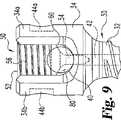
ここで図8−9を参照して、結合部材50によるアンカー30への細長部材80の取り付けを更に説明する。図8において、細長部材80は通路38を通してアンカー30の支持表面40に接するか又は隣接するように位置決めされている。結合部材50は第1のアーム34aと第2のアーム34bとの間の上方開口と整合する。侵入要素54の末端部62は細長部材80に接触するか又は部分的に進入する。図9において、結合部材50は、支持表面60が細長部材80と接触するまでヘッド34内へネジ式に前進して、支持表面40と支持表面60との間で細長部材80をクリンプ(crimp)し、侵入要素は細長部材80を完全に貫通して伸びる。 Referring now to FIGS. 8-9, attachment of the
細長部材80が圧縮可能な材料から作られる場合、細長部材80は支持表面40、60間のそのクリンプされた部分に沿って減少した断面積を有する。侵入要素54はアンカー30のカニューレ42内に少なくとも部分的に受け入れられ、上述のクリンプ作用と組み合わせた侵入要素54による細長部材80の完全な侵入を許容する。侵入要素54は支持部材を提供し、アンカー30内へ細長部材80をスリップさせる傾向を有する長手方向の力により細長部材が伸張又は圧縮されたときに、細長部材80が支持部材に対して作用する。従って、アンカー50内への細長部材80の運動は細長部材80と支持表面40、60との間に発生する摩擦により及び結合部材50の侵入要素54により提供される支え支持により抵抗を受ける。
If the
図10には、本発明に係る別の実施の形態のアンカー130を示す。アンカー130は細長いシャフト132と、ヘッド134とを有する。シャフト132はアンカー30に関して上述したような外ネジ形状136又は他の骨係合構造をそれに沿って有する。図示の実施の形態においては、ヘッド134は第2のアーム134bとこれから離間した第1のアーム134aとの間に細長部材受け入れ部分を有する。第1のアーム134aはその内側にネジ形状135aを有し、第2のアーム134bはその内側にネジ形状135bを有する。ヘッド134は第1のアーム134aと第2のアーム134bとの間を延びるU字状の通路138を画定する。ヘッド134は更に第1のアーム134aと第2のアーム134bとの間を延び、通路138に沿って第1のリップ部146aから第2のリップ部146bまでの支持表面140を有する。
FIG. 10 shows another embodiment of an
アンカー130は支持表面140から通路138内へ延びる侵入要素142の形をした細長部材係合部分を有する。細長部材80は通路138内に配置することができ、侵入要素142が細長部材80を通って延びるように、支持表面140に対して押し付けることができる。侵入要素142は支持部材を提供し、細長部材80をアンカー130内へスリップさせる傾向を有する引っ張り又は圧縮性の長手方向の力に抵抗するように、細長部材80が支持部材に対して作用する。更に、別の実施の形態においては、アンカー130が侵入要素142を具備することが考えられる。
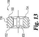
ここで図11−13を参照すると、アンカー30、130へ適用する本発明に係る別の実施の形態の結合部材150を示す。結合部材150は、アンカー30、130と結合部材150との間に位置したときに細長部材80に当接する末端支持表面160を有する。結合部材150はまた工具受け入れ部158のまわりを伸びる突起154の形をした細長部材係合部分をその末端に有する。工具受け入れ部158はプラグ本体152を貫通する貫通穴を提供する。駆動工具は結合部材150をアンカー30、130の内ネジヘッドに係合させるために結合部材150に回転駆動力を適用するように工具受け入れ部158内で位置決めできる。 Referring now to FIGS. 11-13, another embodiment of a
結合部材150は支持表面160とアンカー30、130の通路内の支持表面との間で細長本体80を押圧する。突起154は、細長部材に作用する長手方向の力に抵抗するために、アンカーの支持表面に対してそれとの接触位置で細長部材80を減少した寸法形状へとクリンプする。結合部材150はアンカー30、130の第1のリップ部46a、146aに隣接する第1の位置及びアンカー30、130の第2のリップ部46b、146bに隣接する第2の位置で細長部材80をクリンプする。侵入要素142がアンカー130上に設けられた実施の形態に対しては、侵入要素142は、アンカー130にネジ係合したときに、細長部材80を通って結合部材150内へ伸びる。侵入要素142は侵入要素54に関して上述したものと同様の方法で細長部材80に適用された長手方向の力に対する抵抗を提供する。 The
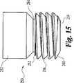
ここで図14−15を参照すると、アンカー30、130へ適用する本発明に係る結合部材250を示す。結合部材250はそのまわりにネジ形状256を備えたプラグ本体252を有する。結合部材250はアンカー30、130と結合部材250との間に位置する細長部材80に当接する末端支持表面260を有する。結合部材250はまた工具受け入れ部158のまわりを伸びる突起254の形をした細長部材係合部分を有する。工具受け入れ部258はプラグ本体252を通って伸びる。駆動工具は結合部材250をアンカー30、130の内ネジヘッドに係合させるために結合部材250へ回転駆動力を適用するように工具受け入れ部258内に位置決めできる。 Referring now to FIGS. 14-15, there is shown a
結合部材250は更にくぼみ264においてプラグ本体252に結合された破断部分262を有する。破断部分262は工具受け入れ部258のまわりに形成された駆動工具受け入れ部分266を有する。図示の実施の形態においては、駆動工具受け入れ部分266は六角形頭の駆動工具を受け入れるように形状づけられる;しかし、他の形状も考えられる。駆動工具は、突起254がその上に加えられた長手方向の力に抵抗するためにアンカーの支持表面に対してそれとの接触位置で細長部材80をクリンプするように、結合部材250をアンカー30、130のヘッド内へ駆動するように駆動工具受け入れ部分266内で位置決めできる。また、突起254はそれとの接触位置で細長部材80内へ部分的に侵入できることが考えられる。破断部分262は、所定量のトルクがそれに作用したときに、くぼみ264においてプラグ本体252から切断する。トルクは、アンカー30、130に関してスリップするのを阻止するのに十分な圧縮力が細長部材80に加えられるように、確立されるが、圧縮力は細長部材80を切断するか又は細長部材を安定素子として無効にするほど大きくはない。 The
侵入要素142をアンカー130上に設けたような実施の形態に対しては、侵入要素142は、アンカー130にネジ係合したときに、細長部材80を通って、結合部材250の受け入れ部258により提供された貫通穴内へ伸びる。破断部分262は、駆動工具が工具受け入れ部258に近い方に位置し、アンカー130のヘッド134内への結合部材250の螺入の際に侵入要素142と抵触しないように、プラグ本体252に関して寸法決めされ、位置決めされる。 For embodiments where the
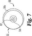
ここで図16−17を参照すると、アンカー30、130へ適用する本発明に係る結合部材350を示す。結合部材350はそのまわりにネジ形状356を備えたプラグ本体352を有する。結合部材350はまたプラグ本体352の末端に取付けられた円筒状の端部材360の形をした細長部材係合部分を有する。端部材360は、プラグ本体352がアンカーのヘッド内に螺入されたときに、端部材360が細長部材80との十分に強固な接触の際に回転しないように、プラグ本体352に関して回転可能である。特定の実施の形態においては、プラグ本体352は端部材360の上方の空洞361内に受け入れられた下方のフランジ353を有する。多数のピン365が端部材360に圧入されるか又は他の方法で取付けられ、プラグ本体352上で端部材360を回転自在に捕縛するようにフランジ353の上方で空洞361内へ伸びる。ここでは、プラグ本体352に端部材360を回転自在に係合させるための他の形状も考えられる。 Referring now to FIGS. 16-17, a
端部材360は、細長部材80がアンカー30、130と結合部材350との間に位置するときに細長部材80に当接する下方の支持表面368を有する。端部材360はまた凹状の表面366のまわりを伸びる突起354を有する。突起354はアンカーの支持表面に対してそれとの接触位置で細長部材80をクリンプするか又はこれに部分的に侵入する。
結合部材360はプラグ本体352を通って少なくとも伸びる工具受け入れ部(図示せず)を有する。工具受け入れ部はアンカーから伸びる侵入要素を受け入れるために端部材360を通って伸びることができる。更に、凹状の表面366が中実で、結合部材350がそれと係合するときにアンカーの侵入要素と接触できること、または、侵入要素のみが細長部材へ部分的に侵入することが考えられる。結合部材350はまた結合部材250に関して上述したような破断部分362及びくぼみ364を有することができる。 The
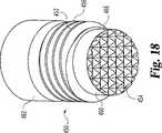
ここで図18を参照すると、アンカー30、130へ適用する本発明に係る結合部材450を示す。結合部材450はそのまわりにネジ形状456を備えたプラグ本体452を有する。結合部材450はまたプラグ本体452に取付けられた円筒状の端部材460の形をした細長部材係合部分を有する。結合部材450はプラグ本体452を通るが端部材460を通らない工具受け入れ部(図示せず)を有する。結合部材450は結合部材250に関して上述したような破断部分462を有することができる。端部材460は第1のリップ部46a、146aと第2のリップ部46b、146bとの間の多数の位置で細長部材に部分的に侵入するか又は細長部材をアンカーの支持表面に対してクリンプする突起454を備えた下方の支持表面466を有する。図示の実施の形態においては、これらの不規則物は複数のピラミッド状の突起の格子により形成される。 Referring now to FIG. 18, a
結合部材450の別の形は図19に示され、符号550で特定する。結合部材550は結合部材450とほぼ同一であり、そのまわりに形成されたネジ形状556を備えたプラグ本体552と、破断部分562と、突起454と同様の突起554を具備した下方の支持表面566を備えた円筒状の端部材560とを有する。結合部材550は更にそこを通って伸び下方の支持表面566で開口する通路558を有する。結合部材550はここで述べる任意の実施の形態のアンカーと一緒に使用できるが、アンカー130が侵入要素142を具備する場合に、結合部材550は特に有用である。その理由は、侵入要素142が細長部材に完全に侵入でき、通路558内に受け入れられることができるからである。 Another form of
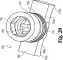
ここで図20−21を参照すると、別の実施の形態の結合部材750を示す。結合部材750はそのまわりにネジ形状756を備えたプラグ本体752を有する。結合部材750は少なくともプラグ本体752を通って伸びる工具受け入れ部(図示せず)を有する。結合部材750はまた結合部材250に関して上述したような破断部分762を有することができる。結合部材750はプラグ本体752に回転自在に係合する端部材760を備えた細長部材係合部分を有する。 Referring now to FIGS. 20-21, another
端部材760は第1の長手方向の延長部760aと、中央部分760cから伸びる第2の長手方向の延長部760bとを有する細長い本体である。中央部分760cはアンカーの支持表面に隣接してアンカーの通路内へ受け入れられるような寸法及び形状を有する。長手方向の延長部760a、760bは、アンカー30、130の通路38、138内に受け入れられアンカーのアーム間で細長部材80の方向にかつ第1のリップ部46a、146a及び第2のリップ部46b、146bのうちの隣接する1つを越えて長手方向に伸びるように、寸法決めされる。下方の支持表面766は第1の突起754aと第2の突起754bとの間で端部材760に沿って形成される。突起754a、754bは細長部材80と接触し、リップ部46a、146a又は46b、146bと隣接する突起754a、754bとの間で細長部材をクリンプする。下方の支持表面766は、摩擦的な支持関係が下方の支持表面766とリップ部46a、146a又は46b、146b間のアンカーの支持表面の全長との間に確立されるように、アンカーの通路内で細長部材80と接触する。
結合部材750の別の形は図22に示され、符号850で特定する。結合部材850は結合部材750とほぼ同一であり、そのまわりでネジ形状856を備えたプラグ本体852と、破断部分862と、くぼみ864と、第1の長手方向の延長部860a、第2の長手方向の延長部860b、中央部分860c及びそれに沿って伸びる下方の支持表面866を備えた端部材860とを有する。アンカー30、130と結合部材850との間での細長部材80の係合は下方の支持表面866及び第1のリップ部46a、146aと第2のリップ部46b、146bとの間のアンカーの支持表面の接触表面積により提供される摩擦係合に全体的に依存する。細長部材80をクリンプするためのアンカーの支持表面の全長の利用は、アンカーの支持表面の一部のみが利用される場合に提供されるよりも一層大きな、結合部材50とアンカー30との間での細長部材80のスリップに対する抵抗を提供する。 Another form of
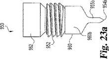
結合部材750の別の形は図23に示され、符号950で特定する。結合部材950は結合部材750とほぼ同一であり、そのまわりでネジ形状956を備えたプラグ本体952と、破断部分962と、くぼみ964と、第1の長手方向の延長部960a、第2の長手方向の延長部960b及びそれに沿って伸びる下方の支持表面966を具備したそれらの間の中央部分860cを備えた端部材960とを有する。結合部材950はまた先細り端部955a、955bをそれぞれ備えた第1の侵入要素954a及び第2の侵入要素954bの形をした長手方法部材係合部分を有する。更に図23aに示すように、侵入要素954a、954bは、アンカー30、130と結合部材950との間に位置する細長部材80へ部分的に又は完全に侵入するのに十分な距離だけ、支持表面966から下方へ伸びる。長手方向の延長部960a、960bは、侵入要素954a、954bが通路38、138の外側で細長部材80に侵入するように、これを取付けたアンカー30、130の通路を越えて細長部材80に沿って長手方向に伸びるように寸法決めされる。 Another form of
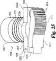
ここで図24−25を参照すると、別の実施の形態の結合部材1050を示す。結合部材1050はそのまわりでネジ形状1056を備えたプラグ本体1052を有する。結合部材1050は少なくともプラグ本体1052を通って伸びる工具受け入れ部(図示せず)を有する。結合部材1050はまた結合部材250に関して上述したような破断部分1062を有することができる。結合部材1050はまたプラグ本体1052に取付けられ、それに関して回転できる細長い本体の形をした端部材1060を有する。 Referring now to FIGS. 24-25, another
端部材1060は第1の長手方向の延長部1060aと、第2の長手方向の延長部1060bと、それらの間の中央部分1060cとを有する。バネ負荷アーム170は一端で第2の長手方向の延長部1060bに枢着結合される。バネ180は端部材1060から離れるようにアーム1070の他端を偏倚する。アーム170はまた、その下側に沿ってそれを横切って形成された複数の歯1074の形をした突起を備えた丸い部分1072を有することができる。細長部材80を矢印Tの方向に引っ張られる(pulled)、即ち伸張される(tensioned)ことができる。その理由は、バネ1080がこのような伸張を許容するように圧縮するからである。細長部材80が矢印Tとは反対の方向へ移動した場合、アーム170は、歯1074が伸張された細長部材80に対してバネ負荷された伸張状態で、細長部材80を暫定的に捕獲する。アーム1070上の歯1074は、結合部材1050が圧縮されたバネ1080によりアンカーに固定されるまで、スリップを阻止するために伸張された細長部材80に摩擦的に係合するか又は部分的に侵入する。 The
本発明の侵入要素及び突起は、細長部材80を完全に貫通できるか又は細長部材80を通って部分的に伸びることができることが考えられる。1つの特定な実施の形態においては、細長部材80内への部分的な侵入の深さはその厚さの約5%に対応することが考えられる。5%ないし100%の範囲の他の侵入深さも考えられる。更に、細長部材80が実質上中実の本体を具備することができ、本発明の侵入要素及び突起は、結合部材がヘッド34内に螺入前進するときに、この中実本体を突き刺すことが考えられる。 It is contemplated that the intrusion elements and protrusions of the present invention can either completely penetrate the
上述したシステム及び装置を考慮して、脊髄運動分節を安定させる方法を説明する。細長部材はこれを取付けるべき脊髄運動分節に沿って伸びるのに十分な長さを有する。アンカーは脊髄運動分節からなる椎骨のそれぞれ1つと係合する。隣接するアンカーは互いに向かって圧縮することができ、細長部材は脊髄運動分節に矯正力を提供するように各圧縮されたアンカーに取付けられる。細長部材はこれを取付けたアンカーに関する細長部材のスリップを阻止するために上述のようにクリンプされるか又は侵入されることができることが考えられる。細長部材80が本発明のアンカー及び結合部材でその長さに沿った任意の位置において侵入又はクリンプされることができるので、細長部材80はその長さに沿って中実で一様の本体を具備することができる。細長部材80は、その長さに沿って、本発明のアンカー及び結合部材と係合するためのいかなる穴、溝穴又は他の係合構造を含む必要がない。従って、外科医は細長部材80に沿った特定の別個の取り付け位置を束縛されず、むしろ、細長部材80に沿った無限数の取り付け位置が提供される。 Considering the system and apparatus described above, a method for stabilizing the spinal motor segment will be described. The elongated member has a length sufficient to extend along the spinal motion segment to which it is to be attached. The anchor engages with each one of the vertebrae that consist of spinal motor segments. Adjacent anchors can be compressed toward each other and an elongate member is attached to each compressed anchor to provide corrective force to the spinal motion segment. It is contemplated that the elongate member can be crimped or penetrated as described above to prevent the elongate member from slipping with respect to the anchor to which it is attached. Since the
脊髄運動分節を安定させる別の方法によれば、細長部材は脊髄運動分節の少なくとも2つの椎骨間を伸びる長さを有する。アンカーは脊髄運動分節の椎骨と係合する。細長部材は脊髄運動分節に所望の矯正力を提供するように伸張され、次いで、結合部材でアンカーに取付けられる。細長部材はこれを取付けたアンカーに関する細長部材のスリップを阻止するために上述のようにクリンプされるか又は侵入されることができることが考えられる。更に、伸張された細長部材が第1のアンカー及び第2のアンカーに取付けられる前に、第1のアンカー及び第2のアンカーを互いに向かって圧縮できることが考えられる。次いで、外科医は任意の余分な長さを除去するために細長部材を切断することができる。 According to another method of stabilizing the spinal motion segment, the elongate member has a length that extends between at least two vertebrae of the spinal motion segment. The anchor engages the vertebrae of the spinal motor segment. The elongated member is stretched to provide the desired corrective force for the spinal motion segment and then attached to the anchor with a coupling member. It is contemplated that the elongate member can be crimped or penetrated as described above to prevent the elongate member from slipping with respect to the anchor to which it is attached. It is further contemplated that the first and second anchors can be compressed toward each other before the elongated members are attached to the first and second anchors. The surgeon can then cut the elongated member to remove any excess length.
図面及び上記の説明において本発明を詳細に図示し、説明したが、これは図示の目的と考えるべきで、特徴を限定するものではなく、好ましい実施の形態のみが図示、説明されたこと及び本発明の精神内に入るすべての変更及び修正が保護されたいことを理解されたい。 While the invention has been illustrated and described in detail in the drawings and foregoing description, the same is to be considered as illustrative and not restrictive in character, and only the preferred embodiments are shown and described. It should be understood that all changes and modifications that come within the spirit of the invention are to be protected.
Claims (16)
Translated fromJapanese上記椎骨に係合可能なシャフト及び上記シャフトから延びるヘッドを有するアンカーであって、上記ヘッドがその中に上記細長部材を受け入れるための通路を画定する、アンカーと;
上記アンカーの上記ヘッドに係合可能な本体、上記本体に結合された端部材、上記端部材の一端に枢着結合された第1の端部を有するアーム、及び、上記アームが上記細長部材と接触するように上記第1の端部とは反対側の上記アームの第2の端部を上記端部材から離れるように偏倚するバネを有する、結合部材と;を備えることを特徴とする装置。In an apparatus for joining an elongated member to a vertebra,
An anchor having a shaft engageable with the vertebra and a head extending from the shaft, the head defining a passage for receiving the elongate member therein;
A main bodyengageable with the head of the anchor; an end member coupled to the main body;an arm having a first end pivotally coupled to one end of the end member; and the arm and the elongated member And a coupling member havinga spring thatbiases the second end of the arm opposite the first end away from the end member to contact .
少なくとも2つの脊椎本体間の距離を跨ぐように寸法決めされ、可撓性の材料で作られた細長部材と;
椎骨に係合可能なシャフト及び上記シャフトから延びるヘッドをそれぞれ有する複数のアンカーであって、上記ヘッドがその中に細長部材受け入れ部分を有し、上記細長部材を上記少なくとも2つの脊椎本体の各々に固定するための上記複数のアンカーと;
上記複数のアンカーの対応する1つに各々取付けることのできる複数の結合要素であって、各上記複数の結合要素が、上記複数のアンカーの上記ヘッドに係合可能な本体、上記本体に結合された端部材、上記端部材の一端に枢着結合された第1の端部を有するアーム、及び、上記アームが上記細長部材と接触するように上記第1の端部とは反対側の上記アームの第2の端部を上記端部材から離れるように偏倚するバネを有する、複数の結合部材と;を有し、
それによって、上記細長部材が、上記少なくとも2つの椎骨間の少なくとも限られた相対変位を許容しながら、上記脊髄運動分節を安定させることを特徴とするシステム。In the system that stabilizes the spinal motor segment,
An elongated member dimensioned to span a distance between at least two spinal bodies and made of a flexible material;
A plurality of anchors each having a shaft engageable with a vertebra and a head extending from the shaft, the head having an elongated member receiving portiontherein, the elongated memberbeing attached to each of the at least two vertebral bodies. A plurality of anchors for securing;
A plurality of coupling elementseach attachable to a corresponding one of the plurality of anchors, wherein each of the plurality of coupling elements is coupled to the heads of the plurality of anchors; An end member, an arm having a first end pivotally coupled to one end of the end member, and the arm opposite the first end so that the arm contacts the elongated member A plurality of coupling members having springs biasing the second end of the first end away from the end member ;
Thereby, the elongate member stabilizes the spinal motion segment while allowing at least limited relative displacement between the at least two vertebrae.
Applications Claiming Priority (2)
| Application Number | Priority Date | Filing Date | Title |
|---|---|---|---|
| US10/013,053US6783527B2 (en) | 2001-10-30 | 2001-10-30 | Flexible spinal stabilization system and method |
| PCT/US2002/033310WO2003037216A2 (en) | 2001-10-30 | 2002-10-07 | Flexible spinal stablization system and method |
Publications (3)
| Publication Number | Publication Date |
|---|---|
| JP2005507705A JP2005507705A (en) | 2005-03-24 |
| JP2005507705A5 JP2005507705A5 (en) | 2008-10-09 |
| JP4316378B2true JP4316378B2 (en) | 2009-08-19 |
Family
ID=21758058
Family Applications (1)
| Application Number | Title | Priority Date | Filing Date |
|---|---|---|---|
| JP2003539564AExpired - LifetimeJP4316378B2 (en) | 2001-10-30 | 2002-10-07 | Device for joining elongated members to vertebrae |
Country Status (5)
| Country | Link |
|---|---|
| US (7) | US6783527B2 (en) |
| EP (1) | EP1450726B1 (en) |
| JP (1) | JP4316378B2 (en) |
| AU (1) | AU2002337896B2 (en) |
| WO (1) | WO2003037216A2 (en) |
Cited By (1)
| Publication number | Priority date | Publication date | Assignee | Title |
|---|---|---|---|---|
| KR101834057B1 (en)* | 2016-01-26 | 2018-04-13 | 김정엽 | Iron core assembly for the treatment of fractures |
Families Citing this family (452)
| Publication number | Priority date | Publication date | Assignee | Title |
|---|---|---|---|---|
| US6273912B1 (en)* | 1996-02-28 | 2001-08-14 | Impra, Inc. | Flanged graft for end-to-side anastomosis |
| US7201751B2 (en) | 1997-01-02 | 2007-04-10 | St. Francis Medical Technologies, Inc. | Supplemental spine fixation device |
| US7306628B2 (en) | 2002-10-29 | 2007-12-11 | St. Francis Medical Technologies | Interspinous process apparatus and method with a selectably expandable spacer |
| US6068630A (en) | 1997-01-02 | 2000-05-30 | St. Francis Medical Technologies, Inc. | Spine distraction implant |
| US7959652B2 (en) | 2005-04-18 | 2011-06-14 | Kyphon Sarl | Interspinous process implant having deployable wings and method of implantation |
| CA2425951C (en)* | 1999-08-18 | 2008-09-16 | Intrinsic Therapeutics, Inc. | Devices and method for nucleus pulposus augmentation and retention |
| US8323341B2 (en) | 2007-09-07 | 2012-12-04 | Intrinsic Therapeutics, Inc. | Impaction grafting for vertebral fusion |
| US7094258B2 (en)* | 1999-08-18 | 2006-08-22 | Intrinsic Therapeutics, Inc. | Methods of reinforcing an annulus fibrosis |
| EP1624832A4 (en) | 1999-08-18 | 2008-12-24 | Intrinsic Therapeutics Inc | Devices and method for augmenting a vertebral disc nucleus |
| US7717961B2 (en) | 1999-08-18 | 2010-05-18 | Intrinsic Therapeutics, Inc. | Apparatus delivery in an intervertebral disc |
| US7972337B2 (en) | 2005-12-28 | 2011-07-05 | Intrinsic Therapeutics, Inc. | Devices and methods for bone anchoring |
| US7998213B2 (en) | 1999-08-18 | 2011-08-16 | Intrinsic Therapeutics, Inc. | Intervertebral disc herniation repair |
| US8187303B2 (en) | 2004-04-22 | 2012-05-29 | Gmedelaware 2 Llc | Anti-rotation fixation element for spinal prostheses |
| US6974478B2 (en)* | 1999-10-22 | 2005-12-13 | Archus Orthopedics, Inc. | Prostheses, systems and methods for replacement of natural facet joints with artificial facet joint surfaces |
| US7691145B2 (en) | 1999-10-22 | 2010-04-06 | Facet Solutions, Inc. | Prostheses, systems and methods for replacement of natural facet joints with artificial facet joint surfaces |
| ATE285207T1 (en)* | 1999-10-22 | 2005-01-15 | Archus Orthopedics Inc | FACET ARTHROPLASTY DEVICES |
| US20050027361A1 (en)* | 1999-10-22 | 2005-02-03 | Reiley Mark A. | Facet arthroplasty devices and methods |
| US7674293B2 (en) | 2004-04-22 | 2010-03-09 | Facet Solutions, Inc. | Crossbar spinal prosthesis having a modular design and related implantation methods |
| US20060241602A1 (en)* | 2000-06-06 | 2006-10-26 | Jackson Roger P | Hooked transverse connector for spinal implant system |
| US20050267477A1 (en)* | 2000-06-06 | 2005-12-01 | Jackson Roger P | Removable medical implant closure |
| US20050187549A1 (en)* | 2000-06-06 | 2005-08-25 | Jackson Roger P. | Removable medical implant closure |
| FR2812186B1 (en)* | 2000-07-25 | 2003-02-28 | Spine Next Sa | FLEXIBLE CONNECTION PIECE FOR SPINAL STABILIZATION |
| FR2812185B1 (en) | 2000-07-25 | 2003-02-28 | Spine Next Sa | SEMI-RIGID CONNECTION PIECE FOR RACHIS STABILIZATION |
| US7833250B2 (en) | 2004-11-10 | 2010-11-16 | Jackson Roger P | Polyaxial bone screw with helically wound capture connection |
| US6579319B2 (en) | 2000-11-29 | 2003-06-17 | Medicinelodge, Inc. | Facet joint replacement |
| US20050080486A1 (en) | 2000-11-29 | 2005-04-14 | Fallin T. Wade | Facet joint replacement |
| US6726689B2 (en) | 2002-09-06 | 2004-04-27 | Roger P. Jackson | Helical interlocking mating guide and advancement structure |
| US8377100B2 (en)* | 2000-12-08 | 2013-02-19 | Roger P. Jackson | Closure for open-headed medical implant |
| US6565605B2 (en) | 2000-12-13 | 2003-05-20 | Medicinelodge, Inc. | Multiple facet joint replacement |
| US6419703B1 (en)* | 2001-03-01 | 2002-07-16 | T. Wade Fallin | Prosthesis for the replacement of a posterior element of a vertebra |
| CA2437575C (en)* | 2001-02-16 | 2009-04-07 | Queen's University At Kingston | Method and device for treating abnormal curvature of the spine |
| US7090698B2 (en) | 2001-03-02 | 2006-08-15 | Facet Solutions | Method and apparatus for spine joint replacement |
| US20160242816A9 (en) | 2001-05-09 | 2016-08-25 | Roger P. Jackson | Dynamic spinal stabilization assembly with elastic bumpers and locking limited travel closure mechanisms |
| US7862587B2 (en) | 2004-02-27 | 2011-01-04 | Jackson Roger P | Dynamic stabilization assemblies, tool set and method |
| US8353932B2 (en) | 2005-09-30 | 2013-01-15 | Jackson Roger P | Polyaxial bone anchor assembly with one-piece closure, pressure insert and plastic elongate member |
| US10729469B2 (en) | 2006-01-09 | 2020-08-04 | Roger P. Jackson | Flexible spinal stabilization assembly with spacer having off-axis core member |
| US10258382B2 (en) | 2007-01-18 | 2019-04-16 | Roger P. Jackson | Rod-cord dynamic connection assemblies with slidable bone anchor attachment members along the cord |
| US8292926B2 (en) | 2005-09-30 | 2012-10-23 | Jackson Roger P | Dynamic stabilization connecting member with elastic core and outer sleeve |
| US6783527B2 (en)* | 2001-10-30 | 2004-08-31 | Sdgi Holdings, Inc. | Flexible spinal stabilization system and method |
| US7285121B2 (en)* | 2001-11-05 | 2007-10-23 | Warsaw Orthopedic, Inc. | Devices and methods for the correction and treatment of spinal deformities |
| US11224464B2 (en) | 2002-05-09 | 2022-01-18 | Roger P. Jackson | Threaded closure with inwardly-facing tool engaging concave radiused structures and axial through-aperture |
| EP1364622B1 (en)* | 2002-05-21 | 2005-07-20 | Spinelab GmbH | Elastical system for stabilising the spine |
| US7052497B2 (en)* | 2002-08-14 | 2006-05-30 | Sdgi Holdings, Inc. | Techniques for spinal surgery and attaching constructs to vertebral elements |
| US7306603B2 (en) | 2002-08-21 | 2007-12-11 | Innovative Spinal Technologies | Device and method for percutaneous placement of lumbar pedicle screws and connecting rods |
| JP4423197B2 (en)* | 2002-08-25 | 2010-03-03 | ザ ユニヴァーシティ オブ ホンコン | Spinal deformity correction device |
| US8876868B2 (en)* | 2002-09-06 | 2014-11-04 | Roger P. Jackson | Helical guide and advancement flange with radially loaded lip |
| WO2006052796A2 (en) | 2004-11-10 | 2006-05-18 | Jackson Roger P | Helical guide and advancement flange with break-off extensions |
| US8257402B2 (en) | 2002-09-06 | 2012-09-04 | Jackson Roger P | Closure for rod receiving orthopedic implant having left handed thread removal |
| US8282673B2 (en) | 2002-09-06 | 2012-10-09 | Jackson Roger P | Anti-splay medical implant closure with multi-surface removal aperture |
| US7909853B2 (en) | 2004-09-23 | 2011-03-22 | Kyphon Sarl | Interspinous process implant including a binder and method of implantation |
| US8048117B2 (en) | 2003-05-22 | 2011-11-01 | Kyphon Sarl | Interspinous process implant and method of implantation |
| US7833246B2 (en) | 2002-10-29 | 2010-11-16 | Kyphon SÀRL | Interspinous process and sacrum implant and method |
| US7931674B2 (en) | 2005-03-21 | 2011-04-26 | Kyphon Sarl | Interspinous process implant having deployable wing and method of implantation |
| US7549999B2 (en) | 2003-05-22 | 2009-06-23 | Kyphon Sarl | Interspinous process distraction implant and method of implantation |
| US8070778B2 (en) | 2003-05-22 | 2011-12-06 | Kyphon Sarl | Interspinous process implant with slide-in distraction piece and method of implantation |
| US20040111088A1 (en)* | 2002-12-06 | 2004-06-10 | Picetti George D. | Multi-rod bone attachment member |
| US7887539B2 (en) | 2003-01-24 | 2011-02-15 | Depuy Spine, Inc. | Spinal rod approximators |
| EP1592893B1 (en)* | 2003-02-12 | 2007-01-24 | Synthes GmbH | Screw comprising an integrated screwdriver |
| US20060200128A1 (en)* | 2003-04-04 | 2006-09-07 | Richard Mueller | Bone anchor |
| US6716214B1 (en) | 2003-06-18 | 2004-04-06 | Roger P. Jackson | Polyaxial bone screw with spline capture connection |
| US8540753B2 (en) | 2003-04-09 | 2013-09-24 | Roger P. Jackson | Polyaxial bone screw with uploaded threaded shank and method of assembly and use |
| US7621918B2 (en) | 2004-11-23 | 2009-11-24 | Jackson Roger P | Spinal fixation tool set and method |
| US7608104B2 (en) | 2003-05-14 | 2009-10-27 | Archus Orthopedics, Inc. | Prostheses, tools and methods for replacement of natural facet joints with artifical facet joint surfaces |
| US20040230304A1 (en) | 2003-05-14 | 2004-11-18 | Archus Orthopedics Inc. | Prostheses, tools and methods for replacement of natural facet joints with artifical facet joint surfaces |
| US7377923B2 (en) | 2003-05-22 | 2008-05-27 | Alphatec Spine, Inc. | Variable angle spinal screw assembly |
| US8926670B2 (en) | 2003-06-18 | 2015-01-06 | Roger P. Jackson | Polyaxial bone screw assembly |
| US8377102B2 (en) | 2003-06-18 | 2013-02-19 | Roger P. Jackson | Polyaxial bone anchor with spline capture connection and lower pressure insert |
| US7967850B2 (en) | 2003-06-18 | 2011-06-28 | Jackson Roger P | Polyaxial bone anchor with helical capture connection, insert and dual locking assembly |
| US8092500B2 (en) | 2007-05-01 | 2012-01-10 | Jackson Roger P | Dynamic stabilization connecting member with floating core, compression spacer and over-mold |
| US7766915B2 (en) | 2004-02-27 | 2010-08-03 | Jackson Roger P | Dynamic fixation assemblies with inner core and outer coil-like member |
| US8366753B2 (en) | 2003-06-18 | 2013-02-05 | Jackson Roger P | Polyaxial bone screw assembly with fixed retaining structure |
| US8257398B2 (en) | 2003-06-18 | 2012-09-04 | Jackson Roger P | Polyaxial bone screw with cam capture |
| US7776067B2 (en) | 2005-05-27 | 2010-08-17 | Jackson Roger P | Polyaxial bone screw with shank articulation pressure insert and method |
| US8137386B2 (en) | 2003-08-28 | 2012-03-20 | Jackson Roger P | Polyaxial bone screw apparatus |
| US8398682B2 (en) | 2003-06-18 | 2013-03-19 | Roger P. Jackson | Polyaxial bone screw assembly |
| US7074238B2 (en)* | 2003-07-08 | 2006-07-11 | Archus Orthopedics, Inc. | Prostheses, tools and methods for replacement of natural facet joints with artificial facet joint surfaces |
| US7625375B2 (en)* | 2003-08-06 | 2009-12-01 | Warsaw Orthopedic, Inc. | Systems and techniques for stabilizing the spine and placing stabilization systems |
| US7763052B2 (en)* | 2003-12-05 | 2010-07-27 | N Spine, Inc. | Method and apparatus for flexible fixation of a spine |
| US7815665B2 (en) | 2003-09-24 | 2010-10-19 | N Spine, Inc. | Adjustable spinal stabilization system |
| US20050203513A1 (en) | 2003-09-24 | 2005-09-15 | Tae-Ahn Jahng | Spinal stabilization device |
| US8979900B2 (en) | 2003-09-24 | 2015-03-17 | DePuy Synthes Products, LLC | Spinal stabilization device |
| US7137985B2 (en)* | 2003-09-24 | 2006-11-21 | N Spine, Inc. | Marking and guidance method and system for flexible fixation of a spine |
| US20050090822A1 (en)* | 2003-10-24 | 2005-04-28 | Dipoto Gene | Methods and apparatus for stabilizing the spine through an access device |
| US20050080414A1 (en)* | 2003-10-14 | 2005-04-14 | Keyer Thomas R. | Spinal fixation hooks and method of spinal fixation |
| US7967826B2 (en) | 2003-10-21 | 2011-06-28 | Theken Spine, Llc | Connector transfer tool for internal structure stabilization systems |
| US7588575B2 (en) | 2003-10-21 | 2009-09-15 | Innovative Spinal Technologies | Extension for use with stabilization systems for internal structures |
| US20050096652A1 (en)* | 2003-10-31 | 2005-05-05 | Burton Charles V. | Integral flexible spine stabilization device and method |
| US7083622B2 (en)* | 2003-11-10 | 2006-08-01 | Simonson Peter M | Artificial facet joint and method |
| US7708764B2 (en)* | 2003-11-10 | 2010-05-04 | Simonson Peter M | Method for creating an artificial facet |
| US7588590B2 (en) | 2003-12-10 | 2009-09-15 | Facet Solutions, Inc | Spinal facet implant with spherical implant apposition surface and bone bed and methods of use |
| US20050131406A1 (en) | 2003-12-15 | 2005-06-16 | Archus Orthopedics, Inc. | Polyaxial adjustment of facet joint prostheses |
| US11419642B2 (en) | 2003-12-16 | 2022-08-23 | Medos International Sarl | Percutaneous access devices and bone anchor assemblies |
| US7527638B2 (en) | 2003-12-16 | 2009-05-05 | Depuy Spine, Inc. | Methods and devices for minimally invasive spinal fixation element placement |
| US7666188B2 (en)* | 2003-12-16 | 2010-02-23 | Depuy Spine, Inc. | Methods and devices for spinal fixation element placement |
| US7179261B2 (en)* | 2003-12-16 | 2007-02-20 | Depuy Spine, Inc. | Percutaneous access devices and bone anchor assemblies |
| US7806914B2 (en)* | 2003-12-31 | 2010-10-05 | Spine Wave, Inc. | Dynamic spinal stabilization system |
| US20050187631A1 (en)* | 2004-01-27 | 2005-08-25 | Sdgi Holdings, Inc. | Prosthetic device |
| US7297146B2 (en)* | 2004-01-30 | 2007-11-20 | Warsaw Orthopedic, Inc. | Orthopedic distraction implants and techniques |
| US8029548B2 (en) | 2008-05-05 | 2011-10-04 | Warsaw Orthopedic, Inc. | Flexible spinal stabilization element and system |
| US7846183B2 (en) | 2004-02-06 | 2010-12-07 | Spinal Elements, Inc. | Vertebral facet joint prosthesis and method of fixation |
| US7476240B2 (en)* | 2004-02-06 | 2009-01-13 | Depuy Spine, Inc. | Devices and methods for inserting a spinal fixation element |
| US8333789B2 (en) | 2007-01-10 | 2012-12-18 | Gmedelaware 2 Llc | Facet joint replacement |
| US8562649B2 (en) | 2004-02-17 | 2013-10-22 | Gmedelaware 2 Llc | System and method for multiple level facet joint arthroplasty and fusion |
| US7993373B2 (en) | 2005-02-22 | 2011-08-09 | Hoy Robert W | Polyaxial orthopedic fastening apparatus |
| US8152810B2 (en) | 2004-11-23 | 2012-04-10 | Jackson Roger P | Spinal fixation tool set and method |
| JP2007525274A (en) | 2004-02-27 | 2007-09-06 | ロジャー・ピー・ジャクソン | Orthopedic implant rod reduction instrument set and method |
| US11241261B2 (en) | 2005-09-30 | 2022-02-08 | Roger P Jackson | Apparatus and method for soft spinal stabilization using a tensionable cord and releasable end structure |
| US7160300B2 (en) | 2004-02-27 | 2007-01-09 | Jackson Roger P | Orthopedic implant rod reduction tool set and method |
| US7547318B2 (en)* | 2004-03-19 | 2009-06-16 | Depuy Spine, Inc. | Spinal fixation element and methods |
| US7645294B2 (en) | 2004-03-31 | 2010-01-12 | Depuy Spine, Inc. | Head-to-head connector spinal fixation system |
| US7717939B2 (en) | 2004-03-31 | 2010-05-18 | Depuy Spine, Inc. | Rod attachment for head to head cross connector |
| US7993366B2 (en)* | 2004-05-27 | 2011-08-09 | Cardiva Medical, Inc. | Self-tensioning vascular occlusion device and method for its use |
| US7678139B2 (en)* | 2004-04-20 | 2010-03-16 | Allez Spine, Llc | Pedicle screw assembly |
| US7406775B2 (en) | 2004-04-22 | 2008-08-05 | Archus Orthopedics, Inc. | Implantable orthopedic device component selection instrument and methods |
| WO2006055186A2 (en) | 2004-10-25 | 2006-05-26 | Archus Orthopedics, Inc. | Spinal prosthesis having a modular design |
| US7914556B2 (en) | 2005-03-02 | 2011-03-29 | Gmedelaware 2 Llc | Arthroplasty revision system and method |
| US7051451B2 (en)* | 2004-04-22 | 2006-05-30 | Archus Orthopedics, Inc. | Facet joint prosthesis measurement and implant tools |
| US7524324B2 (en) | 2004-04-28 | 2009-04-28 | Kyphon Sarl | System and method for an interspinous process implant as a supplement to a spine stabilization implant |
| US7766941B2 (en)* | 2004-05-14 | 2010-08-03 | Paul Kamaljit S | Spinal support, stabilization |
| FR2870718B1 (en)* | 2004-05-25 | 2006-09-22 | Spine Next Sa | TREATMENT ASSEMBLY FOR THE DEGENERATION OF AN INTERVERTEBRAL DISC |
| WO2005117725A2 (en)* | 2004-05-27 | 2005-12-15 | Depuy Spine, Inc. | Tri-joint implant |
| US7901435B2 (en) | 2004-05-28 | 2011-03-08 | Depuy Spine, Inc. | Anchoring systems and methods for correcting spinal deformities |
| US8034085B2 (en) | 2004-05-28 | 2011-10-11 | Depuy Spine, Inc. | Non-fusion spinal correction systems and methods |
| US7507242B2 (en) | 2004-06-02 | 2009-03-24 | Facet Solutions | Surgical measurement and resection framework |
| US7758581B2 (en)* | 2005-03-28 | 2010-07-20 | Facet Solutions, Inc. | Polyaxial reaming apparatus and method |
| US8764801B2 (en) | 2005-03-28 | 2014-07-01 | Gmedelaware 2 Llc | Facet joint implant crosslinking apparatus and method |
| US8858599B2 (en)* | 2004-06-09 | 2014-10-14 | Warsaw Orthopedic, Inc. | Systems and methods for flexible spinal stabilization |
| US9504583B2 (en) | 2004-06-10 | 2016-11-29 | Spinal Elements, Inc. | Implant and method for facet immobilization |
| US7351261B2 (en)* | 2004-06-30 | 2008-04-01 | Depuy Spine, Inc. | Multi-joint implant |
| US8021428B2 (en)* | 2004-06-30 | 2011-09-20 | Depuy Spine, Inc. | Ceramic disc prosthesis |
| US7261738B2 (en) | 2004-06-30 | 2007-08-28 | Depuy Spine, Inc. | C-shaped disc prosthesis |
| US8114158B2 (en)* | 2004-08-03 | 2012-02-14 | Kspine, Inc. | Facet device and method |
| US7658753B2 (en)* | 2004-08-03 | 2010-02-09 | K Spine, Inc. | Device and method for correcting a spinal deformity |
| DE202004020396U1 (en) | 2004-08-12 | 2005-07-07 | Columbus Trading-Partners Pos und Brendel GbR (vertretungsberechtigte Gesellschafter Karin Brendel, 95503 Hummeltal und Bohumila Pos, 95445 Bayreuth) | Child seat for motor vehicles |
| AU2005277363A1 (en) | 2004-08-18 | 2006-03-02 | Fsi Acquisition Sub, Llc | Adjacent level facet arthroplasty devices, spine stabilization systems, and methods |
| US7717938B2 (en) | 2004-08-27 | 2010-05-18 | Depuy Spine, Inc. | Dual rod cross connectors and inserter tools |
| US8012209B2 (en) | 2004-09-23 | 2011-09-06 | Kyphon Sarl | Interspinous process implant including a binder, binder aligner and method of implantation |
| US7651502B2 (en) | 2004-09-24 | 2010-01-26 | Jackson Roger P | Spinal fixation tool set and method for rod reduction and fastener insertion |
| US8092496B2 (en)* | 2004-09-30 | 2012-01-10 | Depuy Spine, Inc. | Methods and devices for posterior stabilization |
| US7896906B2 (en)* | 2004-12-30 | 2011-03-01 | Depuy Spine, Inc. | Artificial facet joint |
| US7766940B2 (en)* | 2004-12-30 | 2010-08-03 | Depuy Spine, Inc. | Posterior stabilization system |
| US20060084976A1 (en)* | 2004-09-30 | 2006-04-20 | Depuy Spine, Inc. | Posterior stabilization systems and methods |
| DE102004048938B4 (en)* | 2004-10-07 | 2015-04-02 | Synthes Gmbh | Device for the dynamic stabilization of vertebral bodies |
| US8267969B2 (en) | 2004-10-20 | 2012-09-18 | Exactech, Inc. | Screw systems and methods for use in stabilization of bone structures |
| US8162985B2 (en) | 2004-10-20 | 2012-04-24 | The Board Of Trustees Of The Leland Stanford Junior University | Systems and methods for posterior dynamic stabilization of the spine |
| US8226690B2 (en) | 2005-07-22 | 2012-07-24 | The Board Of Trustees Of The Leland Stanford Junior University | Systems and methods for stabilization of bone structures |
| US7935134B2 (en) | 2004-10-20 | 2011-05-03 | Exactech, Inc. | Systems and methods for stabilization of bone structures |
| US8025680B2 (en) | 2004-10-20 | 2011-09-27 | Exactech, Inc. | Systems and methods for posterior dynamic stabilization of the spine |
| US8926672B2 (en) | 2004-11-10 | 2015-01-06 | Roger P. Jackson | Splay control closure for open bone anchor |
| US9216041B2 (en) | 2009-06-15 | 2015-12-22 | Roger P. Jackson | Spinal connecting members with tensioned cords and rigid sleeves for engaging compression inserts |
| US9168069B2 (en) | 2009-06-15 | 2015-10-27 | Roger P. Jackson | Polyaxial bone anchor with pop-on shank and winged insert with lower skirt for engaging a friction fit retainer |
| US7875065B2 (en)* | 2004-11-23 | 2011-01-25 | Jackson Roger P | Polyaxial bone screw with multi-part shank retainer and pressure insert |
| US8308782B2 (en) | 2004-11-23 | 2012-11-13 | Jackson Roger P | Bone anchors with longitudinal connecting member engaging inserts and closures for fixation and optional angulation |
| US9980753B2 (en) | 2009-06-15 | 2018-05-29 | Roger P Jackson | pivotal anchor with snap-in-place insert having rotation blocking extensions |
| US8444681B2 (en) | 2009-06-15 | 2013-05-21 | Roger P. Jackson | Polyaxial bone anchor with pop-on shank, friction fit retainer and winged insert |
| WO2006057837A1 (en) | 2004-11-23 | 2006-06-01 | Jackson Roger P | Spinal fixation tool attachment structure |
| WO2006058221A2 (en) | 2004-11-24 | 2006-06-01 | Abdou Samy M | Devices and methods for inter-vertebral orthopedic device placement |
| US20070016196A1 (en)* | 2005-05-10 | 2007-01-18 | Winslow Charles J | Inter-cervical facet implant with implantation tool |
| US8172877B2 (en)* | 2004-12-13 | 2012-05-08 | Kyphon Sarl | Inter-cervical facet implant with surface enhancements |
| US8128660B2 (en)* | 2004-12-13 | 2012-03-06 | Kyphon Sarl | Inter-cervical facet joint implant with locking screw system |
| US8066749B2 (en)* | 2004-12-13 | 2011-11-29 | Warsaw Orthopedic, Inc. | Implant for stabilizing a bone graft during spinal fusion |
| US7763050B2 (en) | 2004-12-13 | 2010-07-27 | Warsaw Orthopedic, Inc. | Inter-cervical facet implant with locking screw and method |
| US8029540B2 (en) | 2005-05-10 | 2011-10-04 | Kyphon Sarl | Inter-cervical facet implant with implantation tool |
| US7776090B2 (en) | 2004-12-13 | 2010-08-17 | Warsaw Orthopedic, Inc. | Inter-cervical facet implant and method |
| US8118838B2 (en)* | 2004-12-13 | 2012-02-21 | Kyphon Sarl | Inter-cervical facet implant with multiple direction articulation joint and method for implanting |
| CA2591848C (en) | 2004-12-27 | 2012-08-07 | N Spine, Inc. | Adjustable spinal stabilization system |
| DE102005005647A1 (en)* | 2005-02-08 | 2006-08-17 | Henning Kloss | Pedicle screw for spinal column stabilizing device, has screw head with two opposed oblong hole shaped recesses, and ball unit including recess for accommodating connecting unit and movably mounted in head |
| US7559929B2 (en)* | 2005-02-18 | 2009-07-14 | Warsaw Orthopedic, Inc. | Implants and methods for positioning same in surgical approaches to the spine |
| US7604654B2 (en) | 2005-02-22 | 2009-10-20 | Stryker Spine | Apparatus and method for dynamic vertebral stabilization |
| US10076361B2 (en) | 2005-02-22 | 2018-09-18 | Roger P. Jackson | Polyaxial bone screw with spherical capture, compression and alignment and retention structures |
| US7901437B2 (en) | 2007-01-26 | 2011-03-08 | Jackson Roger P | Dynamic stabilization member with molded connection |
| US7951172B2 (en) | 2005-03-04 | 2011-05-31 | Depuy Spine Sarl | Constrained motion bone screw assembly |
| US7951175B2 (en) | 2005-03-04 | 2011-05-31 | Depuy Spine, Inc. | Instruments and methods for manipulating a vertebra |
| US7722647B1 (en) | 2005-03-14 | 2010-05-25 | Facet Solutions, Inc. | Apparatus and method for posterior vertebral stabilization |
| US8496686B2 (en) | 2005-03-22 | 2013-07-30 | Gmedelaware 2 Llc | Minimally invasive spine restoration systems, devices, methods and kits |
| US7909826B2 (en)* | 2005-03-24 | 2011-03-22 | Depuy Spine, Inc. | Low profile spinal tethering methods |
| US20060276801A1 (en)* | 2005-04-04 | 2006-12-07 | Yerby Scott A | Inter-cervical facet implant distraction tool |
| US8163261B2 (en)* | 2005-04-05 | 2012-04-24 | Voltaix, Llc | System and method for making Si2H6 and higher silanes |
| US7708762B2 (en)* | 2005-04-08 | 2010-05-04 | Warsaw Orthopedic, Inc. | Systems, devices and methods for stabilization of the spinal column |
| US7794481B2 (en) | 2005-04-22 | 2010-09-14 | Warsaw Orthopedic, Inc. | Force limiting coupling assemblies for spinal implants |
| TWI375545B (en) | 2005-04-25 | 2012-11-01 | Synthes Gmbh | Bone anchor with locking cap and method of spinal fixation |
| US7695499B2 (en)* | 2005-04-29 | 2010-04-13 | Warsaw Orthopedic, Inc. | System, devices and method for augmenting existing fusion constructs |
| US20060264937A1 (en)* | 2005-05-04 | 2006-11-23 | White Patrick M | Mobile spine stabilization device |
| US20060264935A1 (en)* | 2005-05-04 | 2006-11-23 | White Patrick M | Orthopedic stabilization device |
| US7828830B2 (en) | 2005-05-12 | 2010-11-09 | Lanx, Inc. | Dynamic spinal stabilization |
| US20060271048A1 (en)* | 2005-05-12 | 2006-11-30 | Jeffery Thramann | Pedicle screw based vertebral body stabilization apparatus |
| US20060264252A1 (en)* | 2005-05-23 | 2006-11-23 | White Gehrig H | System and method for providing a host console for use with an electronic card game |
| US7951169B2 (en)* | 2005-06-10 | 2011-05-31 | Depuy Spine, Inc. | Posterior dynamic stabilization cross connectors |
| US8523865B2 (en) | 2005-07-22 | 2013-09-03 | Exactech, Inc. | Tissue splitter |
| US7625394B2 (en)* | 2005-08-05 | 2009-12-01 | Warsaw Orthopedic, Inc. | Coupling assemblies for spinal implants |
| CH705709B1 (en) | 2005-08-29 | 2013-05-15 | Bird Biedermann Ag | Spinal implant. |
| CH701479B1 (en)* | 2005-09-13 | 2011-01-31 | Bird Biedermann Ag | Vertebral column implant, has connecting unit, which is clamped by clamping structure in form-fit manner between retainer and spacer, where clamping is strengthened under increased axial force of elastic bar |
| DE502006002049D1 (en)* | 2005-09-13 | 2008-12-24 | Bird Biedermann Ag | Dynamic clamping device for spinal implant |
| US20080243194A1 (en)* | 2005-09-26 | 2008-10-02 | The Regents Of The University Of California | Articulating instrumentation for dynamic spinal stabilization |
| WO2007038429A1 (en) | 2005-09-27 | 2007-04-05 | Endius, Inc. | Methods and apparatuses for stabilizing the spine through an access device |
| US7879074B2 (en)* | 2005-09-27 | 2011-02-01 | Depuy Spine, Inc. | Posterior dynamic stabilization systems and methods |
| US7993376B2 (en)* | 2005-09-29 | 2011-08-09 | Depuy Spine, Inc. | Methods of implanting a motion segment repair system |
| US8105368B2 (en) | 2005-09-30 | 2012-01-31 | Jackson Roger P | Dynamic stabilization connecting member with slitted core and outer sleeve |
| US7722651B2 (en) | 2005-10-21 | 2010-05-25 | Depuy Spine, Inc. | Adjustable bone screw assembly |
| GB0521582D0 (en) | 2005-10-22 | 2005-11-30 | Depuy Int Ltd | An implant for supporting a spinal column |
| US8357181B2 (en) | 2005-10-27 | 2013-01-22 | Warsaw Orthopedic, Inc. | Intervertebral prosthetic device for spinal stabilization and method of implanting same |
| US8137385B2 (en) | 2005-10-31 | 2012-03-20 | Stryker Spine | System and method for dynamic vertebral stabilization |
| ES2313189T3 (en)* | 2005-11-17 | 2009-03-01 | Biedermann Motech Gmbh | POLIAXIAL SCREW FOR FLEXIBLE BAR. |
| US8100946B2 (en)* | 2005-11-21 | 2012-01-24 | Synthes Usa, Llc | Polyaxial bone anchors with increased angulation |
| US8034078B2 (en) | 2008-05-30 | 2011-10-11 | Globus Medical, Inc. | System and method for replacement of spinal motion segment |
| US7704271B2 (en) | 2005-12-19 | 2010-04-27 | Abdou M Samy | Devices and methods for inter-vertebral orthopedic device placement |
| ES2323008T3 (en)* | 2005-12-23 | 2009-07-03 | Biedermann Motech Gmbh | DEVICE OF DYNAMIC STABILIZATION OF BONES OR VERTEBRAS. |
| DE602005008265D1 (en)* | 2005-12-23 | 2008-08-28 | Biedermann Motech Gmbh | Flexible stabilization device for the dynamic stabilization of bones or vertebrae |
| US20070173822A1 (en)* | 2006-01-13 | 2007-07-26 | Sdgi Holdings, Inc. | Use of a posterior dynamic stabilization system with an intradiscal device |
| GB0600662D0 (en) | 2006-01-13 | 2006-02-22 | Depuy Int Ltd | Spinal support rod kit |
| US8348952B2 (en) | 2006-01-26 | 2013-01-08 | Depuy International Ltd. | System and method for cooling a spinal correction device comprising a shape memory material for corrective spinal surgery |
| US7578849B2 (en) | 2006-01-27 | 2009-08-25 | Warsaw Orthopedic, Inc. | Intervertebral implants and methods of use |
| US7815663B2 (en) | 2006-01-27 | 2010-10-19 | Warsaw Orthopedic, Inc. | Vertebral rods and methods of use |
| US7682376B2 (en) | 2006-01-27 | 2010-03-23 | Warsaw Orthopedic, Inc. | Interspinous devices and methods of use |
| US20070233089A1 (en)* | 2006-02-17 | 2007-10-04 | Endius, Inc. | Systems and methods for reducing adjacent level disc disease |
| US20070233064A1 (en)* | 2006-02-17 | 2007-10-04 | Holt Development L.L.C. | Apparatus and method for flexible spinal fixation |
| US20080269804A1 (en)* | 2006-02-17 | 2008-10-30 | Holt Development L.L.C. | Apparatus and method for flexible spinal fixation |
| DE102006010116A1 (en)* | 2006-02-27 | 2007-08-30 | Karl Storz Gmbh & Co.Kg | Anchor element for knot-free fixation of tissue to a bone |
| US7850717B2 (en)* | 2006-03-01 | 2010-12-14 | Warsaw Orthopedic, Inc. | Bone anchors having two or more portions exhibiting different performance characteristics and method of forming the same |
| WO2007121271A2 (en) | 2006-04-11 | 2007-10-25 | Synthes (U.S.A) | Minimally invasive fixation system |
| US20070270813A1 (en)* | 2006-04-12 | 2007-11-22 | Laszlo Garamszegi | Pedicle screw assembly |
| EP2012686B1 (en)* | 2006-04-18 | 2013-10-02 | Joseph Nicholas Logan | Spinal rod system |
| US7914559B2 (en)* | 2006-05-30 | 2011-03-29 | Warsaw Orthopedic, Inc. | Locking device and method employing a posted member to control positioning of a stabilization member of a bone stabilization system |
| US20080058808A1 (en) | 2006-06-14 | 2008-03-06 | Spartek Medical, Inc. | Implant system and method to treat degenerative disorders of the spine |
| US20080015601A1 (en)* | 2006-06-14 | 2008-01-17 | Michael Castro | Reduction device and method of use |
| WO2008003047A2 (en)* | 2006-06-28 | 2008-01-03 | Synthes (U.S.A.) | Dynamic fixation system |
| WO2008008511A2 (en)* | 2006-07-14 | 2008-01-17 | Laszlo Garamszegi | Pedicle screw assembly with inclined surface seat |
| US8702755B2 (en) | 2006-08-11 | 2014-04-22 | Gmedelaware 2 Llc | Angled washer polyaxial connection for dynamic spine prosthesis |
| US9526525B2 (en)* | 2006-08-22 | 2016-12-27 | Neuropro Technologies, Inc. | Percutaneous system for dynamic spinal stabilization |
| US8317830B2 (en) | 2006-08-29 | 2012-11-27 | Warsaw Orthopedic, Inc. | Orthopaedic screw system with linear motion |
| ES2336815T5 (en)* | 2006-09-15 | 2013-05-16 | Biedermann Technologies Gmbh & Co. Kg | Bone anchoring device |
| US7918857B2 (en) | 2006-09-26 | 2011-04-05 | Depuy Spine, Inc. | Minimally invasive bone anchor extensions |
| US8361130B2 (en)* | 2006-10-06 | 2013-01-29 | Depuy Spine, Inc. | Bone screw fixation |
| US8096996B2 (en) | 2007-03-20 | 2012-01-17 | Exactech, Inc. | Rod reducer |
| US20080177311A1 (en)* | 2006-10-30 | 2008-07-24 | St. Francis Medical Technologies, Inc. | Facet joint implant sizing tool |
| US8361117B2 (en) | 2006-11-08 | 2013-01-29 | Depuy Spine, Inc. | Spinal cross connectors |
| US8740941B2 (en) | 2006-11-10 | 2014-06-03 | Lanx, Inc. | Pedicle based spinal stabilization with adjacent vertebral body support |
| US20080140202A1 (en)* | 2006-12-08 | 2008-06-12 | Randall Noel Allard | Energy-Storing Spinal Implants and Methods of Use |
| CA2670988C (en) | 2006-12-08 | 2014-03-25 | Roger P. Jackson | Tool system for dynamic spinal implants |
| CN102525623B (en) | 2006-12-10 | 2015-04-29 | 帕拉迪格脊骨有限责任公司 | Posterior functionally dynamic stabilization system |
| FR2910267B1 (en)* | 2006-12-21 | 2009-01-23 | Ldr Medical Soc Par Actions Si | VERTEBRAL SUPPORT DEVICE |
| US8636783B2 (en)* | 2006-12-29 | 2014-01-28 | Zimmer Spine, Inc. | Spinal stabilization systems and methods |
| WO2008082836A1 (en)* | 2006-12-29 | 2008-07-10 | Abbott Spine Inc. | Spinal stabilization systems and methods |
| CA2675037A1 (en) | 2007-01-10 | 2008-07-17 | Facet Solutions, Inc. | Taper-locking fixation system |
| US8747445B2 (en) | 2007-01-15 | 2014-06-10 | Ebi, Llc | Spinal fixation device |
| US8475498B2 (en) | 2007-01-18 | 2013-07-02 | Roger P. Jackson | Dynamic stabilization connecting member with cord connection |
| US7931676B2 (en)* | 2007-01-18 | 2011-04-26 | Warsaw Orthopedic, Inc. | Vertebral stabilizer |
| US11224463B2 (en) | 2007-01-18 | 2022-01-18 | Roger P. Jackson | Dynamic stabilization connecting member with pre-tensioned flexible core member |
| US8366745B2 (en) | 2007-05-01 | 2013-02-05 | Jackson Roger P | Dynamic stabilization assembly having pre-compressed spacers with differential displacements |
| US8435268B2 (en)* | 2007-01-19 | 2013-05-07 | Reduction Technologies, Inc. | Systems, devices and methods for the correction of spinal deformities |
| US10792074B2 (en) | 2007-01-22 | 2020-10-06 | Roger P. Jackson | Pivotal bone anchor assemly with twist-in-place friction fit insert |
| US8182511B2 (en)* | 2007-01-29 | 2012-05-22 | Polaris Biotechnology, Inc. | Craniospinal fusion method and apparatus |
| US20090036894A1 (en)* | 2007-01-29 | 2009-02-05 | Polaris Biotechnology, Inc. | Method of treating a neurological condition through correction and stabilization of the clivo-axial angle |
| US8403965B2 (en)* | 2007-01-29 | 2013-03-26 | Polaris Biotechnology, Inc. | Vertebra attachment method and system |
| US8556939B2 (en)* | 2008-01-08 | 2013-10-15 | Fraser Cummins Henderson | Mathematical relationship of strain, neurological dysfunction and abnormal behavior resulting from neurological dysfunction of the brainstem |
| US8083743B2 (en) | 2007-01-29 | 2011-12-27 | Polaris Biotechnology, Inc. | Craniospinal fusion method and apparatus |
| US9827023B2 (en) | 2007-01-29 | 2017-11-28 | Life Spine, Inc. | Craniospinal fusion method and apparatus |
| US8034081B2 (en) | 2007-02-06 | 2011-10-11 | CollabComl, LLC | Interspinous dynamic stabilization implant and method of implanting |
| US20080195153A1 (en)* | 2007-02-08 | 2008-08-14 | Matthew Thompson | Dynamic spinal deformity correction |
| US9414861B2 (en)* | 2007-02-09 | 2016-08-16 | Transcendental Spine, Llc | Dynamic stabilization device |
| US8012177B2 (en) | 2007-02-12 | 2011-09-06 | Jackson Roger P | Dynamic stabilization assembly with frusto-conical connection |
| US10842535B2 (en) | 2007-02-14 | 2020-11-24 | William R. Krause | Flexible spine components having multiple slots |
| US9138263B2 (en) | 2007-02-14 | 2015-09-22 | William R. Krause | Flexible spine components |
| US8470002B2 (en)* | 2007-02-20 | 2013-06-25 | Warsaw Orthopedic, Inc. | Resorbable release mechanism for a surgical tether and methods of use |
| US8992533B2 (en) | 2007-02-22 | 2015-03-31 | Spinal Elements, Inc. | Vertebral facet joint drill and method of use |
| EP2813190B1 (en) | 2007-02-22 | 2017-04-26 | Spinal Elements, Inc. | Vertebral facet joint drill |
| EP2301456B1 (en)* | 2007-02-23 | 2013-04-17 | Biedermann Technologies GmbH & Co. KG | Rod connector for stabilizing vertebrae |
| WO2008134703A2 (en)* | 2007-04-30 | 2008-11-06 | Globus Medical, Inc. | Flexible spine stabilization system |
| US10383660B2 (en) | 2007-05-01 | 2019-08-20 | Roger P. Jackson | Soft stabilization assemblies with pretensioned cords |
| US8979904B2 (en) | 2007-05-01 | 2015-03-17 | Roger P Jackson | Connecting member with tensioned cord, low profile rigid sleeve and spacer with torsion control |
| US8197517B1 (en) | 2007-05-08 | 2012-06-12 | Theken Spine, Llc | Frictional polyaxial screw assembly |
| US7942910B2 (en) | 2007-05-16 | 2011-05-17 | Ortho Innovations, Llc | Polyaxial bone screw |
| US8197518B2 (en) | 2007-05-16 | 2012-06-12 | Ortho Innovations, Llc | Thread-thru polyaxial pedicle screw system |
| US7942911B2 (en) | 2007-05-16 | 2011-05-17 | Ortho Innovations, Llc | Polyaxial bone screw |
| US7942909B2 (en) | 2009-08-13 | 2011-05-17 | Ortho Innovations, Llc | Thread-thru polyaxial pedicle screw system |
| US7947065B2 (en) | 2008-11-14 | 2011-05-24 | Ortho Innovations, Llc | Locking polyaxial ball and socket fastener |
| US7951173B2 (en) | 2007-05-16 | 2011-05-31 | Ortho Innovations, Llc | Pedicle screw implant system |
| CA2690038C (en) | 2007-05-31 | 2012-11-27 | Roger P. Jackson | Dynamic stabilization connecting member with pre-tensioned solid core |
| US8021396B2 (en) | 2007-06-05 | 2011-09-20 | Spartek Medical, Inc. | Configurable dynamic spinal rod and method for dynamic stabilization of the spine |
| US8048128B2 (en) | 2007-06-05 | 2011-11-01 | Spartek Medical, Inc. | Revision system and method for a dynamic stabilization and motion preservation spinal implantation system and method |
| US8052722B2 (en) | 2007-06-05 | 2011-11-08 | Spartek Medical, Inc. | Dual deflection rod system for a dynamic stabilization and motion preservation spinal implantation system and method |
| US8092501B2 (en) | 2007-06-05 | 2012-01-10 | Spartek Medical, Inc. | Dynamic spinal rod and method for dynamic stabilization of the spine |
| US8109970B2 (en) | 2007-06-05 | 2012-02-07 | Spartek Medical, Inc. | Deflection rod system with a deflection contouring shield for a spine implant and method |
| US8114134B2 (en) | 2007-06-05 | 2012-02-14 | Spartek Medical, Inc. | Spinal prosthesis having a three bar linkage for motion preservation and dynamic stabilization of the spine |
| US8083772B2 (en) | 2007-06-05 | 2011-12-27 | Spartek Medical, Inc. | Dynamic spinal rod assembly and method for dynamic stabilization of the spine |
| US8048115B2 (en) | 2007-06-05 | 2011-11-01 | Spartek Medical, Inc. | Surgical tool and method for implantation of a dynamic bone anchor |
| US8048123B2 (en) | 2007-06-05 | 2011-11-01 | Spartek Medical, Inc. | Spine implant with a deflection rod system and connecting linkages and method |
| EP2155086B1 (en) | 2007-06-06 | 2016-05-04 | K2M, Inc. | Medical device to correct deformity |
| US20110172708A1 (en)* | 2007-06-22 | 2011-07-14 | Simpirica Spine, Inc. | Methods and systems for increasing the bending stiffness of a spinal segment with elongation limit |
| US20090005815A1 (en)* | 2007-06-28 | 2009-01-01 | Scott Ely | Dynamic stabilization system |
| US9439681B2 (en) | 2007-07-20 | 2016-09-13 | DePuy Synthes Products, Inc. | Polyaxial bone fixation element |
| DE602007007466D1 (en)* | 2007-07-20 | 2010-08-12 | Biedermann Motech Gmbh | Bone anchoring device |
| PL2170192T3 (en)* | 2007-07-20 | 2011-07-29 | Synthes Gmbh | Polyaxial bone fixation element |
| EP2178451A2 (en)* | 2007-08-07 | 2010-04-28 | Synthes GmbH | Dynamic cable system |
| US20110196492A1 (en)* | 2007-09-07 | 2011-08-11 | Intrinsic Therapeutics, Inc. | Bone anchoring systems |
| US20090088782A1 (en)* | 2007-09-28 | 2009-04-02 | Missoum Moumene | Flexible Spinal Rod With Elastomeric Jacket |
| US8414588B2 (en) | 2007-10-04 | 2013-04-09 | Depuy Spine, Inc. | Methods and devices for minimally invasive spinal connection element delivery |
| US20090093843A1 (en)* | 2007-10-05 | 2009-04-09 | Lemoine Jeremy J | Dynamic spine stabilization system |
| US20090099608A1 (en)* | 2007-10-12 | 2009-04-16 | Aesculap Implant Systems, Inc. | Rod assembly for dynamic posterior stabilization |
| US8911477B2 (en) | 2007-10-23 | 2014-12-16 | Roger P. Jackson | Dynamic stabilization member with end plate support and cable core extension |
| GB0720762D0 (en) | 2007-10-24 | 2007-12-05 | Depuy Spine Sorl | Assembly for orthopaedic surgery |
| AU2008316604B2 (en) | 2007-10-25 | 2014-11-06 | Smith & Nephew, Inc. | Anchor assembly |
| US8252028B2 (en) | 2007-12-19 | 2012-08-28 | Depuy Spine, Inc. | Posterior dynamic stabilization device |
| US9232968B2 (en) | 2007-12-19 | 2016-01-12 | DePuy Synthes Products, Inc. | Polymeric pedicle rods and methods of manufacturing |
| US20090177237A1 (en)* | 2008-01-04 | 2009-07-09 | Spartek Medical, Inc. | Cervical spine implant system and method |
| WO2009089395A2 (en)* | 2008-01-08 | 2009-07-16 | Polaris Biotechnology, Inc. | Osteointegration apparatus |
| US9277940B2 (en)* | 2008-02-05 | 2016-03-08 | Zimmer Spine, Inc. | System and method for insertion of flexible spinal stabilization element |
| US8097024B2 (en) | 2008-02-26 | 2012-01-17 | Spartek Medical, Inc. | Load-sharing bone anchor having a deflectable post and method for stabilization of the spine |
| US8057517B2 (en) | 2008-02-26 | 2011-11-15 | Spartek Medical, Inc. | Load-sharing component having a deflectable post and centering spring and method for dynamic stabilization of the spine |
| US8337536B2 (en) | 2008-02-26 | 2012-12-25 | Spartek Medical, Inc. | Load-sharing bone anchor having a deflectable post with a compliant ring and method for stabilization of the spine |
| US8048125B2 (en) | 2008-02-26 | 2011-11-01 | Spartek Medical, Inc. | Versatile offset polyaxial connector and method for dynamic stabilization of the spine |
| US8211155B2 (en) | 2008-02-26 | 2012-07-03 | Spartek Medical, Inc. | Load-sharing bone anchor having a durable compliant member and method for dynamic stabilization of the spine |
| US8083775B2 (en) | 2008-02-26 | 2011-12-27 | Spartek Medical, Inc. | Load-sharing bone anchor having a natural center of rotation and method for dynamic stabilization of the spine |
| US8267979B2 (en) | 2008-02-26 | 2012-09-18 | Spartek Medical, Inc. | Load-sharing bone anchor having a deflectable post and axial spring and method for dynamic stabilization of the spine |
| US8333792B2 (en) | 2008-02-26 | 2012-12-18 | Spartek Medical, Inc. | Load-sharing bone anchor having a deflectable post and method for dynamic stabilization of the spine |
| US8007518B2 (en) | 2008-02-26 | 2011-08-30 | Spartek Medical, Inc. | Load-sharing component having a deflectable post and method for dynamic stabilization of the spine |
| US8608746B2 (en) | 2008-03-10 | 2013-12-17 | DePuy Synthes Products, LLC | Derotation instrument with reduction functionality |
| US8709015B2 (en) | 2008-03-10 | 2014-04-29 | DePuy Synthes Products, LLC | Bilateral vertebral body derotation system |
| US20090234388A1 (en)* | 2008-03-15 | 2009-09-17 | Warsaw Orthopedic, Inc. | Spinal Stabilization Connecting Element and System |
| US8926660B2 (en)* | 2008-03-26 | 2015-01-06 | Anthony Alexander | Systems and methods of anchoring surgical wires, catheters, and other medical objects |
| ES2353033T5 (en)* | 2008-03-28 | 2014-01-20 | Biedermann Technologies Gmbh & Co. Kg | Bone anchoring device |
| US9017384B2 (en)* | 2008-05-13 | 2015-04-28 | Stryker Spine | Composite spinal rod |
| US8206421B2 (en)* | 2008-05-15 | 2012-06-26 | Warsaw Othropedic, Inc. | Methods and devices for insertion of tethers through subcutaneous screw heads |
| US8685026B2 (en)* | 2008-05-23 | 2014-04-01 | Warsaw Orthopedic, Inc. | Devices and methods for releasing tension on a surgical tether |
| EP2328519B1 (en)* | 2008-06-05 | 2014-12-31 | Alphatec Spine, Inc. | Modular anterior locking interbody cage |
| US10973556B2 (en) | 2008-06-17 | 2021-04-13 | DePuy Synthes Products, Inc. | Adjustable implant assembly |
| ES2375526T3 (en)* | 2008-06-19 | 2012-03-01 | Biedermann Motech Gmbh | BONE ANCHORAGE ASSEMBLY. |
| US20090326583A1 (en)* | 2008-06-25 | 2009-12-31 | Missoum Moumene | Posterior Dynamic Stabilization System With Flexible Ligament |
| US20090326584A1 (en)* | 2008-06-27 | 2009-12-31 | Michael Andrew Slivka | Spinal Dynamic Stabilization Rods Having Interior Bumpers |
| WO2010003139A1 (en) | 2008-07-03 | 2010-01-07 | Krause William R | Flexible spine components having a concentric slot |
| US8974494B2 (en) | 2008-07-17 | 2015-03-10 | Smith & Nephew, Inc. | Surgical devices |
| AU2010260521C1 (en) | 2008-08-01 | 2013-08-01 | Roger P. Jackson | Longitudinal connecting member with sleeved tensioned cords |
| EP2484300B1 (en)* | 2008-09-05 | 2015-05-20 | Biedermann Technologies GmbH & Co. KG | Stabilization device for bones, in particular for the spinal column |
| EP2355725B1 (en) | 2008-09-05 | 2017-03-08 | Synthes GmbH | Bone fixation assembly |
| JP5815407B2 (en) | 2008-09-12 | 2015-11-17 | ジンテス ゲゼルシャフト ミット ベシュレンクテル ハフツング | Spinal stabilization and guided fixation system |
| KR20110081208A (en) | 2008-09-29 | 2011-07-13 | 신세스 게엠바하 | Multi-Axis Bottom-Loading Screw and Rod Assemblies |
| EP2174608B1 (en)* | 2008-10-08 | 2012-08-01 | Biedermann Technologies GmbH & Co. KG | Bone anchoring device and stabilization device for bone parts or vertebrae |
| US20100094344A1 (en)* | 2008-10-14 | 2010-04-15 | Kyphon Sarl | Pedicle-Based Posterior Stabilization Members and Methods of Use |
| US8388659B1 (en) | 2008-10-17 | 2013-03-05 | Theken Spine, Llc | Spondylolisthesis screw and instrument for implantation |
| CA2742399A1 (en) | 2008-11-03 | 2010-06-03 | Dustin M. Harvey | Uni-planar bone fixation assembly |
| US20100114165A1 (en)* | 2008-11-04 | 2010-05-06 | Abbott Spine, Inc. | Posterior dynamic stabilization system with pivoting collars |
| US8828058B2 (en) | 2008-11-11 | 2014-09-09 | Kspine, Inc. | Growth directed vertebral fixation system with distractible connector(s) and apical control |
| US8075603B2 (en) | 2008-11-14 | 2011-12-13 | Ortho Innovations, Llc | Locking polyaxial ball and socket fastener |
| US9247967B2 (en)* | 2008-12-03 | 2016-02-02 | Warsaw Orthopedic, Inc. | Rod and anchor system and method for using |
| WO2010078029A1 (en) | 2008-12-17 | 2010-07-08 | Synthes Usa, Llc | Posterior spine dynamic stabilizer |
| US8641734B2 (en) | 2009-02-13 | 2014-02-04 | DePuy Synthes Products, LLC | Dual spring posterior dynamic stabilization device with elongation limiting elastomers |
| US8118840B2 (en) | 2009-02-27 | 2012-02-21 | Warsaw Orthopedic, Inc. | Vertebral rod and related method of manufacture |
| US8357182B2 (en) | 2009-03-26 | 2013-01-22 | Kspine, Inc. | Alignment system with longitudinal support features |
| KR20120013312A (en) | 2009-04-15 | 2012-02-14 | 신세스 게엠바하 | Orthodontic Connectors for Spinal Structures |
| CN102497828B (en) | 2009-05-20 | 2015-09-09 | 斯恩蒂斯有限公司 | What patient installed retracts part |
| EP2440145A4 (en)* | 2009-06-08 | 2013-12-11 | Reduction Technologies Inc | Systems, methods and devices for correcting spinal deformities |
| US8998959B2 (en) | 2009-06-15 | 2015-04-07 | Roger P Jackson | Polyaxial bone anchors with pop-on shank, fully constrained friction fit retainer and lock and release insert |
| US11229457B2 (en) | 2009-06-15 | 2022-01-25 | Roger P. Jackson | Pivotal bone anchor assembly with insert tool deployment |
| CN103826560A (en) | 2009-06-15 | 2014-05-28 | 罗杰.P.杰克逊 | Polyaxial Bone Anchor with Socket Stem and Winged Inserts with Friction Fit Compression Collars |
| US9668771B2 (en) | 2009-06-15 | 2017-06-06 | Roger P Jackson | Soft stabilization assemblies with off-set connector |
| US20100318129A1 (en)* | 2009-06-16 | 2010-12-16 | Kspine, Inc. | Deformity alignment system with reactive force balancing |
| CA2764841A1 (en) | 2009-06-17 | 2010-12-23 | Synthes Usa, Llc | Revision connector for spinal constructs |
| US8267968B2 (en)* | 2009-06-24 | 2012-09-18 | Neuropro Technologies, Inc. | Percutaneous system for dynamic spinal stabilization |
| US9320543B2 (en) | 2009-06-25 | 2016-04-26 | DePuy Synthes Products, Inc. | Posterior dynamic stabilization device having a mobile anchor |
| US20110066187A1 (en)* | 2009-09-11 | 2011-03-17 | Zimmer Spine, Inc. | Spinal stabilization system |
| US9168071B2 (en) | 2009-09-15 | 2015-10-27 | K2M, Inc. | Growth modulation system |
| US9011494B2 (en) | 2009-09-24 | 2015-04-21 | Warsaw Orthopedic, Inc. | Composite vertebral rod system and methods of use |
| EP2485654B1 (en) | 2009-10-05 | 2021-05-05 | Jackson P. Roger | Polyaxial bone anchor with non-pivotable retainer and pop-on shank, some with friction fit |
| US8663289B2 (en)* | 2009-10-29 | 2014-03-04 | Warsaw Orthopedic, Inc. | Pedicle screw head extender |
| JP2013510659A (en) | 2009-11-10 | 2013-03-28 | スミス アンド ネフュー インコーポレーテッド | Tissue repair device |
| CN102695465A (en) | 2009-12-02 | 2012-09-26 | 斯帕泰克医疗股份有限公司 | Low profile spinal prosthesis incorporating a bone anchor having a deflectable post and a compound spinal rod |
| US8764806B2 (en) | 2009-12-07 | 2014-07-01 | Samy Abdou | Devices and methods for minimally invasive spinal stabilization and instrumentation |
| US8968367B2 (en)* | 2010-01-05 | 2015-03-03 | The Johns Hopkins University | Compression-distraction spinal fixation system and kit |
| US9445844B2 (en) | 2010-03-24 | 2016-09-20 | DePuy Synthes Products, Inc. | Composite material posterior dynamic stabilization spring rod |
| US20110245875A1 (en)* | 2010-04-05 | 2011-10-06 | Neurosurj Research & Development, LLC | Sublaminar wired screwed device for spinal fusion |
| US8535318B2 (en) | 2010-04-23 | 2013-09-17 | DePuy Synthes Products, LLC | Minimally invasive instrument set, devices and related methods |
| US20110270321A1 (en) | 2010-04-30 | 2011-11-03 | Warsaw Orthopedic, Inc. | Engaging Member With a Cavity-Base for Engaging a Connecting Element to a Bone Anchor |
| US12383311B2 (en) | 2010-05-14 | 2025-08-12 | Roger P. Jackson | Pivotal bone anchor assembly and method for use thereof |
| US20110307015A1 (en) | 2010-06-10 | 2011-12-15 | Spartek Medical, Inc. | Adaptive spinal rod and methods for stabilization of the spine |
| US10603083B1 (en) | 2010-07-09 | 2020-03-31 | Theken Spine, Llc | Apparatus and method for limiting a range of angular positions of a screw |
| US9084634B1 (en) | 2010-07-09 | 2015-07-21 | Theken Spine, Llc | Uniplanar screw |
| WO2012030712A1 (en) | 2010-08-30 | 2012-03-08 | Zimmer Spine, Inc. | Polyaxial pedicle screw |
| AU2011299558A1 (en) | 2010-09-08 | 2013-05-02 | Roger P. Jackson | Dynamic stabilization members with elastic and inelastic sections |
| AU2011324058A1 (en) | 2010-11-02 | 2013-06-20 | Roger P. Jackson | Polyaxial bone anchor with pop-on shank and pivotable retainer |
| US20120214127A1 (en)* | 2011-02-22 | 2012-08-23 | Warsaw Orthopedic, Inc. | Dental implant system with separable drive and method |
| US9271765B2 (en) | 2011-02-24 | 2016-03-01 | Spinal Elements, Inc. | Vertebral facet joint fusion implant and method for fusion |
| USD724733S1 (en) | 2011-02-24 | 2015-03-17 | Spinal Elements, Inc. | Interbody bone implant |
| US8740949B2 (en) | 2011-02-24 | 2014-06-03 | Spinal Elements, Inc. | Methods and apparatus for stabilizing bone |
| JP5865479B2 (en) | 2011-03-24 | 2016-02-17 | ロジャー・ピー・ジャクソン | Multiaxial bone anchor with compound joint and pop-mounted shank |
| CN103717159B (en) | 2011-05-27 | 2016-08-17 | 新特斯有限责任公司 | Minimally Invasive Spinal Fixation System Including Vertebral Alignment Features |
| JP6158176B2 (en) | 2011-06-03 | 2017-07-05 | ケイツーエム インコーポレイテッドK2M,Inc. | Spine correction system |
| FR2977138B1 (en)* | 2011-06-30 | 2014-02-28 | Implanet | DEVICE FOR FIXING VERTEBRAL |
| US9993269B2 (en)* | 2011-07-15 | 2018-06-12 | Globus Medical, Inc. | Orthopedic fixation devices and methods of installation thereof |
| US8845728B1 (en) | 2011-09-23 | 2014-09-30 | Samy Abdou | Spinal fixation devices and methods of use |
| EP2574296B1 (en)* | 2011-09-28 | 2016-03-02 | Biedermann Technologies GmbH & Co. KG | Bone anchoring assembly |
| EP2747670A4 (en) | 2011-10-05 | 2015-06-24 | Mark A Dodson | Modular retractor and related method |
| WO2013052626A1 (en)* | 2011-10-05 | 2013-04-11 | The Unversity Of Akron | Reduced shock breakaway set screw for use with a surgical construct |
| USD739935S1 (en) | 2011-10-26 | 2015-09-29 | Spinal Elements, Inc. | Interbody bone implant |
| WO2014172632A2 (en) | 2011-11-16 | 2014-10-23 | Kspine, Inc. | Spinal correction and secondary stabilization |
| US9468468B2 (en) | 2011-11-16 | 2016-10-18 | K2M, Inc. | Transverse connector for spinal stabilization system |
| US8920472B2 (en) | 2011-11-16 | 2014-12-30 | Kspine, Inc. | Spinal correction and secondary stabilization |
| US9468469B2 (en) | 2011-11-16 | 2016-10-18 | K2M, Inc. | Transverse coupler adjuster spinal correction systems and methods |
| US9451987B2 (en) | 2011-11-16 | 2016-09-27 | K2M, Inc. | System and method for spinal correction |
| WO2013073975A2 (en)* | 2011-11-18 | 2013-05-23 | Orthopaedic International, Inc. | Parallel rod connector |
| US8956361B2 (en) | 2011-12-19 | 2015-02-17 | Amendia, Inc. | Extended tab bone screw system |
| US9622786B2 (en)* | 2012-01-09 | 2017-04-18 | Apifix Ltd. | Spinal cage |
| US8911479B2 (en) | 2012-01-10 | 2014-12-16 | Roger P. Jackson | Multi-start closures for open implants |
| US9561055B1 (en) | 2012-01-18 | 2017-02-07 | Neurosurj Research and Development, LLC | Spinal fixation method and apparatus |
| US8641736B2 (en)* | 2012-01-20 | 2014-02-04 | Warsaw Orthopedic, Inc. | Vertebral fastener system |
| US8961570B2 (en) | 2012-01-24 | 2015-02-24 | Warsaw Othopedic, Inc. | Spinal correction system and method |
| US8430916B1 (en) | 2012-02-07 | 2013-04-30 | Spartek Medical, Inc. | Spinal rod connectors, methods of use, and spinal prosthesis incorporating spinal rod connectors |
| US20130226240A1 (en) | 2012-02-22 | 2013-08-29 | Samy Abdou | Spinous process fixation devices and methods of use |
| US9198767B2 (en) | 2012-08-28 | 2015-12-01 | Samy Abdou | Devices and methods for spinal stabilization and instrumentation |
| US9101426B2 (en) | 2012-10-11 | 2015-08-11 | Stryker Trauma Sa | Cable plug |
| US9320617B2 (en) | 2012-10-22 | 2016-04-26 | Cogent Spine, LLC | Devices and methods for spinal stabilization and instrumentation |
| US8911478B2 (en) | 2012-11-21 | 2014-12-16 | Roger P. Jackson | Splay control closure for open bone anchor |
| US10058354B2 (en) | 2013-01-28 | 2018-08-28 | Roger P. Jackson | Pivotal bone anchor assembly with frictional shank head seating surfaces |
| US8852239B2 (en) | 2013-02-15 | 2014-10-07 | Roger P Jackson | Sagittal angle screw with integral shank and receiver |
| USD765853S1 (en) | 2013-03-14 | 2016-09-06 | Spinal Elements, Inc. | Flexible elongate member with a portion configured to receive a bone anchor |
| US9743959B2 (en) | 2013-03-14 | 2017-08-29 | Atlas Spine, Inc. | Low profile spinal fixation system |
| US9820784B2 (en) | 2013-03-14 | 2017-11-21 | Spinal Elements, Inc. | Apparatus for spinal fixation and methods of use |
| US9421044B2 (en) | 2013-03-14 | 2016-08-23 | Spinal Elements, Inc. | Apparatus for bone stabilization and distraction and methods of use |
| US9453526B2 (en) | 2013-04-30 | 2016-09-27 | Degen Medical, Inc. | Bottom-loading anchor assembly |
| EP2826429B1 (en)* | 2013-07-19 | 2016-09-14 | Biedermann Technologies GmbH & Co. KG | Polyaxial bone anchoring device |
| US9468471B2 (en) | 2013-09-17 | 2016-10-18 | K2M, Inc. | Transverse coupler adjuster spinal correction systems and methods |
| US9456855B2 (en) | 2013-09-27 | 2016-10-04 | Spinal Elements, Inc. | Method of placing an implant between bone portions |
| US9839450B2 (en) | 2013-09-27 | 2017-12-12 | Spinal Elements, Inc. | Device and method for reinforcement of a facet |
| US9566092B2 (en) | 2013-10-29 | 2017-02-14 | Roger P. Jackson | Cervical bone anchor with collet retainer and outer locking sleeve |
| US9717533B2 (en) | 2013-12-12 | 2017-08-01 | Roger P. Jackson | Bone anchor closure pivot-splay control flange form guide and advancement structure |
| US9451993B2 (en) | 2014-01-09 | 2016-09-27 | Roger P. Jackson | Bi-radial pop-on cervical bone anchor |
| US10758274B1 (en) | 2014-05-02 | 2020-09-01 | Nuvasive, Inc. | Spinal fixation constructs and related methods |
| US9597119B2 (en) | 2014-06-04 | 2017-03-21 | Roger P. Jackson | Polyaxial bone anchor with polymer sleeve |
| US10064658B2 (en) | 2014-06-04 | 2018-09-04 | Roger P. Jackson | Polyaxial bone anchor with insert guides |
| US10499968B2 (en) | 2014-08-08 | 2019-12-10 | Stryker European Holdings I, Llc | Cable plugs for bone plates |
| US11478275B2 (en) | 2014-09-17 | 2022-10-25 | Spinal Elements, Inc. | Flexible fastening band connector |
| DE102014223112A1 (en)* | 2014-11-12 | 2016-05-12 | Gebr. Brasseler Gmbh & Co. Kg | Device for clamping vertebrae of the human spine |
| AU2016212009C1 (en) | 2015-01-27 | 2021-02-25 | Spinal Elements, Inc. | Facet joint implant |
| WO2016172677A1 (en)* | 2015-04-24 | 2016-10-27 | K2M, Inc. | Tethering screw system |
| US9848919B2 (en)* | 2015-05-05 | 2017-12-26 | Warsaw Orthopedic, Inc. | Spinal construct and methods of use |
| EP3100692A1 (en) | 2015-06-04 | 2016-12-07 | Zimmer Spine | Spinal dynamic stabilization system |
| US10857003B1 (en) | 2015-10-14 | 2020-12-08 | Samy Abdou | Devices and methods for vertebral stabilization |
| US9924935B2 (en) | 2015-10-23 | 2018-03-27 | Smith & Nephew, Inc. | Suture anchor assembly with slip fit tip |
| WO2017127532A1 (en)* | 2016-01-19 | 2017-07-27 | K2M, Inc. | Spinal correction system and method of use thereof |
| US10744000B1 (en) | 2016-10-25 | 2020-08-18 | Samy Abdou | Devices and methods for vertebral bone realignment |
| US10973648B1 (en) | 2016-10-25 | 2021-04-13 | Samy Abdou | Devices and methods for vertebral bone realignment |
| US10507043B1 (en) | 2017-10-11 | 2019-12-17 | Seaspine Orthopedics Corporation | Collet for a polyaxial screw assembly |
| US11020149B2 (en)* | 2018-02-28 | 2021-06-01 | Globus Medical Inc. | Scoliosis correction systems, methods, and instruments |
| US11179248B2 (en) | 2018-10-02 | 2021-11-23 | Samy Abdou | Devices and methods for spinal implantation |
| US10893888B2 (en) | 2019-05-02 | 2021-01-19 | Warsaw Orthopedic, Inc. | Spinal implant system and method |
| BR112021022695A2 (en) | 2019-05-22 | 2021-12-28 | Spinal Elements Inc | Bone tethering and bone tethering inserter |
| US11457959B2 (en) | 2019-05-22 | 2022-10-04 | Spinal Elements, Inc. | Bone tie and bone tie inserter |
| US20210121203A1 (en)* | 2019-10-29 | 2021-04-29 | Globus Medical, Inc. | Sublaminar band clamp |
| WO2021127251A1 (en)* | 2019-12-17 | 2021-06-24 | Jackson Roger P | Bone anchor assembly with closed ring retainer and internal snap ring |
| US20210186565A1 (en)* | 2019-12-20 | 2021-06-24 | Warsaw Orthopedic, Inc. | Anti-Splay Head and Set Screw for Spinal Fixation |
| WO2021163313A1 (en) | 2020-02-14 | 2021-08-19 | Spinal Elements, Inc. | Bone tie methods |
| US12318124B2 (en) | 2021-11-29 | 2025-06-03 | Warsaw Orthopedic, Inc. | Continuous fiber bone screw and method of manufacture |
| US12369952B2 (en) | 2021-12-10 | 2025-07-29 | Spinal Elements, Inc. | Bone tie and portal |
Family Cites Families (58)
| Publication number | Priority date | Publication date | Assignee | Title |
|---|---|---|---|---|
| US36221A (en)* | 1862-08-19 | Improvement in locks | ||
| BE434038A (en)* | 1938-04-28 | |||
| US3963322A (en)* | 1975-01-23 | 1976-06-15 | Ite Imperial Corporation | Torque controlling set screw for use with the cable of solderless connectors, or the like |
| GB1551706A (en) | 1975-04-28 | 1979-08-30 | Downs Surgical Ltd | Surgical implant |
| US4743260A (en)* | 1985-06-10 | 1988-05-10 | Burton Charles V | Method for a flexible stabilization system for a vertebral column |
| US4731084A (en) | 1986-03-14 | 1988-03-15 | Richards Medical Company | Prosthetic ligament |
| US4764068A (en)* | 1987-03-06 | 1988-08-16 | Sps Technologies, Inc. | Knurled cup-point set screw |
| USRE36221E (en) | 1989-02-03 | 1999-06-01 | Breard; Francis Henri | Flexible inter-vertebral stabilizer as well as process and apparatus for determining or verifying its tension before installation on the spinal column |
| FR2642645B1 (en) | 1989-02-03 | 1992-08-14 | Breard Francis | FLEXIBLE INTERVERTEBRAL STABILIZER AND METHOD AND APPARATUS FOR CONTROLLING ITS VOLTAGE BEFORE PLACEMENT ON THE RACHIS |
| FR2642643B1 (en) | 1989-02-09 | 1991-05-10 | Vignaud Jean Louis | SPINAL INSTRUMENTATION FOR UNIVERSAL PEDICULAR FIXATION WITH MICROMETRIC ADJUSTMENT DIAPASON SCREW |
| US5062843A (en) | 1990-02-07 | 1991-11-05 | Mahony Iii Thomas H | Interference fixation screw with integral instrumentation |
| FR2659225B1 (en) | 1990-03-08 | 1995-09-08 | Sofamor | TRANSVERSE FIXING DEVICE FOR PROVIDING A RIGID CROSS-LINK BETWEEN TWO RODS OF A SPINAL OSTEOSYNTHESIS SYSTEM. |
| US5102412A (en)* | 1990-06-19 | 1992-04-07 | Chaim Rogozinski | System for instrumentation of the spine in the treatment of spinal deformities |
| US5129900B1 (en) | 1990-07-24 | 1998-12-29 | Acromed Corp | Spinal column retaining method and apparatus |
| FR2666981B1 (en) | 1990-09-21 | 1993-06-25 | Commarmond Jacques | SYNTHETIC LIGAMENT VERTEBRAL. |
| FR2672202B1 (en) | 1991-02-05 | 1993-07-30 | Safir | BONE SURGICAL IMPLANT, ESPECIALLY FOR INTERVERTEBRAL STABILIZER. |
| DE9104025U1 (en)* | 1991-04-03 | 1992-07-30 | Waldemar Link Gmbh & Co, 2000 Hamburg | Bone plate arrangement |
| FR2676354B1 (en) | 1991-05-17 | 1997-11-07 | Vignaud Jean Louis | LOCKABLE CONNECTION DEVICE OF SPINAL OSTEOSYNTHESIS ANCHORING ELEMENTS. |
| GB9110778D0 (en) | 1991-05-18 | 1991-07-10 | Middleton Jeffrey K | Apparatus for use in surgery |
| US5261911A (en) | 1991-06-18 | 1993-11-16 | Allen Carl | Anterolateral spinal fixation system |
| FR2680461B1 (en) | 1991-08-19 | 1993-11-26 | Fabrication Mat Orthopedique | IMPLANT FOR OSTEOSYNTHESIS DEVICE, ESPECIALLY OF THE RACHIS, AND CORRESPONDING DEVICE FOR ITS PLACEMENT. |
| US5257993A (en) | 1991-10-04 | 1993-11-02 | Acromed Corporation | Top-entry rod retainer |
| AU672596B2 (en) | 1992-02-14 | 1996-10-10 | Smith & Nephew, Inc. | Polymeric screws and coatings for surgical uses |
| US5382248A (en) | 1992-09-10 | 1995-01-17 | H. D. Medical, Inc. | System and method for stabilizing bone segments |
| ATE197665T1 (en) | 1992-11-02 | 2000-12-15 | Sulzer Orthopaedie Ag | ANCHORING FOR AN ARTIFICIAL BAND |
| FR2697992B1 (en) | 1992-11-18 | 1994-12-30 | Eurosurgical | Device for attaching to a rod of an organ, in particular for spinal orthopedic instrumentation. |
| DE4243951C2 (en)* | 1992-12-23 | 1997-07-03 | Plus Endoprothetik Ag | Device for stiffening a spinal column section consisting of at least two vertebrae |
| US5397356A (en) | 1993-01-15 | 1995-03-14 | Depuy Inc. | Pin for securing a replacement ligament to a bone |
| US5350380A (en) | 1993-01-15 | 1994-09-27 | Depuy Inc. | Method for securing a ligament replacement in a bone |
| FR2705226B1 (en) | 1993-05-17 | 1995-07-07 | Tornier Sa | Spine fixator to maintain a spine. |
| US5379505A (en) | 1993-06-16 | 1995-01-10 | Lock-N-Stitch International | Method for repairing cracks |
| WO1995013755A1 (en) | 1993-11-19 | 1995-05-26 | Cross Medical Products, Inc. | Rod anchor seat having sliding closure member |
| US5466237A (en)* | 1993-11-19 | 1995-11-14 | Cross Medical Products, Inc. | Variable locking stabilizer anchor seat and screw |
| DE4339804A1 (en) | 1993-11-23 | 1995-06-01 | Haerle Anton | Power transmission link for osteosynthesis work |
| ATE180402T1 (en) | 1994-02-28 | 1999-06-15 | Sulzer Orthopaedie Ag | STABILIZATION OF ADJACENT BACK VERTEBRATE |
| US5507747A (en) | 1994-03-09 | 1996-04-16 | Yuan; Hansen A. | Vertebral fixation device |
| DE9409123U1 (en)* | 1994-06-04 | 1994-09-01 | Howmedica GmbH, 24232 Schönkirchen | Device for stabilizing or compressing or distracting sections of the spine |
| ES2152973T3 (en) | 1994-06-30 | 2001-02-16 | Sulzer Orthopadie Ag | DEVICE FOR THE CONNECTION OF VERTEBRAS. |
| US5658264A (en) | 1994-11-10 | 1997-08-19 | Target Therapeutics, Inc. | High performance spiral-wound catheter |
| US5643260A (en) | 1995-02-14 | 1997-07-01 | Smith & Nephew, Inc. | Orthopedic fixation system |
| FR2734147B1 (en) | 1995-05-19 | 1997-10-10 | Klein Jean Michel | IMPLANTABLE OSTEOSYNTHESIS DEVICE |
| US5643266A (en) | 1995-06-05 | 1997-07-01 | Li Medical Technologies, Inc. | Method and apparatus for securing ligaments |
| US5562663A (en) | 1995-06-07 | 1996-10-08 | Danek Medical, Inc. | Implant interconnection mechanism |
| US6193719B1 (en) | 1995-08-24 | 2001-02-27 | Sofamor S.N.C. | Threaded clamping plug for interconnecting two implants of a spinal osteosynthesis instrumentation or other implants |
| US5697929A (en) | 1995-10-18 | 1997-12-16 | Cross Medical Products, Inc. | Self-limiting set screw for use with spinal implant systems |
| US5782831A (en)* | 1996-11-06 | 1998-07-21 | Sdgi Holdings, Inc. | Method an device for spinal deformity reduction using a cable and a cable tensioning system |
| US6224596B1 (en)* | 1997-01-06 | 2001-05-01 | Roger P. Jackson | Set screw for use with osteosynthesis apparatus |
| US6004349A (en) | 1997-01-06 | 1999-12-21 | Jackson; Roger P. | Set screw for use with osteosynthesis apparatus |
| ES2297092T3 (en)* | 1997-02-11 | 2008-05-01 | Warsaw Orthopedic, Inc. | PREVIOUS CERVICAL PLATE OF UNIQUE BLOCK. |
| US6139550A (en)* | 1997-02-11 | 2000-10-31 | Michelson; Gary K. | Skeletal plating system |
| US6287308B1 (en)* | 1997-07-14 | 2001-09-11 | Sdgi Holdings, Inc. | Methods and apparatus for fusionless treatment of spinal deformities |
| US6056753A (en)* | 1998-07-13 | 2000-05-02 | Jackson; Roger P. | Set screw for use with osteosynthesis apparatus |
| US6530929B1 (en)* | 1999-10-20 | 2003-03-11 | Sdgi Holdings, Inc. | Instruments for stabilization of bony structures |
| DE50007759D1 (en)* | 1999-11-25 | 2004-10-21 | Sulzer Orthopedics Ltd | Surgical instrument for tensioning a cable-like tensioning element |
| US6224598B1 (en) | 2000-02-16 | 2001-05-01 | Roger P. Jackson | Bone screw threaded plug closure with central set screw |
| KR200200582Y1 (en)* | 2000-03-15 | 2000-10-16 | 최길운 | Prosthesis for connecting bone |
| US6652526B1 (en)* | 2001-10-05 | 2003-11-25 | Ruben P. Arafiles | Spinal stabilization rod fastener |
| US6783527B2 (en)* | 2001-10-30 | 2004-08-31 | Sdgi Holdings, Inc. | Flexible spinal stabilization system and method |
- 2001
- 2001-10-30USUS10/013,053patent/US6783527B2/ennot_activeExpired - Lifetime
- 2002
- 2002-10-07WOPCT/US2002/033310patent/WO2003037216A2/enactiveApplication Filing
- 2002-10-07JPJP2003539564Apatent/JP4316378B2/ennot_activeExpired - Lifetime
- 2002-10-07AUAU2002337896Apatent/AU2002337896B2/ennot_activeExpired
- 2002-10-07EPEP02773799.8Apatent/EP1450726B1/ennot_activeExpired - Lifetime
- 2004
- 2004-03-04USUS10/793,308patent/US7018379B2/ennot_activeExpired - Lifetime
- 2006
- 2006-01-20USUS11/336,253patent/US7828826B2/ennot_activeExpired - Lifetime
- 2010
- 2010-09-02USUS12/807,331patent/US8142483B2/ennot_activeExpired - Fee Related
- 2012
- 2012-03-05USUS13/411,731patent/US9358045B2/ennot_activeExpired - Lifetime
- 2016
- 2016-05-09USUS15/149,906patent/US10206715B2/ennot_activeExpired - Fee Related
- 2019
- 2019-01-10USUS16/244,681patent/US10898230B2/ennot_activeExpired - Fee Related
Cited By (1)
| Publication number | Priority date | Publication date | Assignee | Title |
|---|---|---|---|---|
| KR101834057B1 (en)* | 2016-01-26 | 2018-04-13 | 김정엽 | Iron core assembly for the treatment of fractures |
Also Published As
| Publication number | Publication date |
|---|---|
| AU2002337896B2 (en) | 2006-09-14 |
| US8142483B2 (en) | 2012-03-27 |
| WO2003037216A2 (en) | 2003-05-08 |
| US9358045B2 (en) | 2016-06-07 |
| US10206715B2 (en) | 2019-02-19 |
| US6783527B2 (en) | 2004-08-31 |
| EP1450726A1 (en) | 2004-09-01 |
| US7018379B2 (en) | 2006-03-28 |
| US20120165875A1 (en) | 2012-06-28 |
| US20190142473A1 (en) | 2019-05-16 |
| US7828826B2 (en) | 2010-11-09 |
| US20030083657A1 (en) | 2003-05-01 |
| US20040172025A1 (en) | 2004-09-02 |
| US20100331890A1 (en) | 2010-12-30 |
| US10898230B2 (en) | 2021-01-26 |
| JP2005507705A (en) | 2005-03-24 |
| EP1450726B1 (en) | 2015-05-20 |
| US20060122599A1 (en) | 2006-06-08 |
| US20160249953A1 (en) | 2016-09-01 |
Similar Documents
| Publication | Publication Date | Title |
|---|---|---|
| JP4316378B2 (en) | Device for joining elongated members to vertebrae | |
| AU2002337896A1 (en) | Flexible spinal stablization system and method | |
| US11707298B2 (en) | Dynamic spinal stabilization assembly with elastic bumpers and locking limited travel closure mechanisms | |
| EP2349035B1 (en) | Dynamic spinal stabilization assembly with torsion and shear control | |
| US7468064B2 (en) | Systems and methods for positioning implants relative to bone anchors in surgical approaches to the spine | |
| US9155566B2 (en) | Adjustable bone anchor assembly | |
| US20100010542A1 (en) | Flexible spinal stbilization assembly with spacer having off-axis core member | |
| CA2589952A1 (en) | Side-loading bone anchor | |
| JP2006503672A (en) | Multi-axis cross-connect system for spinal implants | |
| KR20080042863A (en) | Connection assembly for spinal implant | |
| US20140142699A1 (en) | Surgical implant for widening a vertebral canal | |
| US11419651B2 (en) | Systems and methods for a pedicle screw assembly with anchor deployment |
Legal Events
| Date | Code | Title | Description |
|---|---|---|---|
| A621 | Written request for application examination | Free format text:JAPANESE INTERMEDIATE CODE: A621 Effective date:20050509 | |
| A711 | Notification of change in applicant | Free format text:JAPANESE INTERMEDIATE CODE: A712 Effective date:20061011 | |
| A131 | Notification of reasons for refusal | Free format text:JAPANESE INTERMEDIATE CODE: A131 Effective date:20080221 | |
| A601 | Written request for extension of time | Free format text:JAPANESE INTERMEDIATE CODE: A601 Effective date:20080521 | |
| A602 | Written permission of extension of time | Free format text:JAPANESE INTERMEDIATE CODE: A602 Effective date:20080528 | |
| A524 | Written submission of copy of amendment under article 19 pct | Free format text:JAPANESE INTERMEDIATE CODE: A524 Effective date:20080821 | |
| A131 | Notification of reasons for refusal | Free format text:JAPANESE INTERMEDIATE CODE: A131 Effective date:20080925 | |
| A601 | Written request for extension of time | Free format text:JAPANESE INTERMEDIATE CODE: A601 Effective date:20081225 | |
| A602 | Written permission of extension of time | Free format text:JAPANESE INTERMEDIATE CODE: A602 Effective date:20090108 | |
| A521 | Request for written amendment filed | Free format text:JAPANESE INTERMEDIATE CODE: A523 Effective date:20090325 | |
| TRDD | Decision of grant or rejection written | ||
| A01 | Written decision to grant a patent or to grant a registration (utility model) | Free format text:JAPANESE INTERMEDIATE CODE: A01 Effective date:20090424 | |
| A01 | Written decision to grant a patent or to grant a registration (utility model) | Free format text:JAPANESE INTERMEDIATE CODE: A01 | |
| A61 | First payment of annual fees (during grant procedure) | Free format text:JAPANESE INTERMEDIATE CODE: A61 Effective date:20090520 | |
| R150 | Certificate of patent or registration of utility model | Ref document number:4316378 Country of ref document:JP Free format text:JAPANESE INTERMEDIATE CODE: R150 Free format text:JAPANESE INTERMEDIATE CODE: R150 | |
| FPAY | Renewal fee payment (event date is renewal date of database) | Free format text:PAYMENT UNTIL: 20120529 Year of fee payment:3 | |
| FPAY | Renewal fee payment (event date is renewal date of database) | Free format text:PAYMENT UNTIL: 20130529 Year of fee payment:4 | |
| R250 | Receipt of annual fees | Free format text:JAPANESE INTERMEDIATE CODE: R250 | |
| R250 | Receipt of annual fees | Free format text:JAPANESE INTERMEDIATE CODE: R250 | |
| R250 | Receipt of annual fees | Free format text:JAPANESE INTERMEDIATE CODE: R250 | |
| R250 | Receipt of annual fees | Free format text:JAPANESE INTERMEDIATE CODE: R250 | |
| R250 | Receipt of annual fees | Free format text:JAPANESE INTERMEDIATE CODE: R250 | |
| R250 | Receipt of annual fees | Free format text:JAPANESE INTERMEDIATE CODE: R250 | |
| R250 | Receipt of annual fees | Free format text:JAPANESE INTERMEDIATE CODE: R250 | |
| R250 | Receipt of annual fees | Free format text:JAPANESE INTERMEDIATE CODE: R250 | |
| R250 | Receipt of annual fees | Free format text:JAPANESE INTERMEDIATE CODE: R250 | |
| R250 | Receipt of annual fees | Free format text:JAPANESE INTERMEDIATE CODE: R250 | |
| R250 | Receipt of annual fees | Free format text:JAPANESE INTERMEDIATE CODE: R250 | |
| EXPY | Cancellation because of completion of term |