JP4316298B2 - Electric vehicle control device - Google Patents
Electric vehicle control deviceDownload PDFInfo
- Publication number
- JP4316298B2 JP4316298B2JP2003158184AJP2003158184AJP4316298B2JP 4316298 B2JP4316298 B2JP 4316298B2JP 2003158184 AJP2003158184 AJP 2003158184AJP 2003158184 AJP2003158184 AJP 2003158184AJP 4316298 B2JP4316298 B2JP 4316298B2
- Authority
- JP
- Japan
- Prior art keywords
- overhead line
- calculation unit
- voltage
- pattern
- electric vehicle
- Prior art date
- Legal status (The legal status is an assumption and is not a legal conclusion. Google has not performed a legal analysis and makes no representation as to the accuracy of the status listed.)
- Expired - Fee Related
Links
Images


Classifications
- Y—GENERAL TAGGING OF NEW TECHNOLOGICAL DEVELOPMENTS; GENERAL TAGGING OF CROSS-SECTIONAL TECHNOLOGIES SPANNING OVER SEVERAL SECTIONS OF THE IPC; TECHNICAL SUBJECTS COVERED BY FORMER USPC CROSS-REFERENCE ART COLLECTIONS [XRACs] AND DIGESTS
- Y02—TECHNOLOGIES OR APPLICATIONS FOR MITIGATION OR ADAPTATION AGAINST CLIMATE CHANGE
- Y02T—CLIMATE CHANGE MITIGATION TECHNOLOGIES RELATED TO TRANSPORTATION
- Y02T10/00—Road transport of goods or passengers
- Y02T10/60—Other road transportation technologies with climate change mitigation effect
- Y02T10/72—Electric energy management in electromobility
Landscapes
- Electric Propulsion And Braking For Vehicles (AREA)
Description
Translated fromJapanese【0001】
【発明の属する技術分野】
本発明は電気車制御装置に関する。
【0002】
【従来の技術】
電気車駆動用の電動機に電力を供給するための可変電圧可変周波数インバータ装置(以下、単にインバータと略称する)と、インバータの直流側の正負端子間にスイッチング手段及びそれに直列に接続された抵抗器を備えた電気車制御装置では、スイッチング手段を制御することによって抵抗器での電気ブレーキエネルギーの消費量を制御している(例えば、特許文献1参照。)。
【0003】
図10はこの種の電気車制御装置の主回路構成を示す回路図である。同図において、直流架線1から直流電力を集電する直流電力集電器2には、遮断器3及びフィルタリアクトル4を介して、インバータ8の直流側端子の正側が接続されている。このインバータ8の直流側端子の負側は接地装置10を介してレール11に接続されている。インバータ8の正側端子と負側端子との間に、抵抗器5及びスイッチング手段6の直列接続回路、フィルタコンデンサ7、並びに架線電圧検出手段13が接続されており、さらに、遮断器3とフィルタリアクトル4との間の直流経路に入力電流検出手段12が設けられている。インバータ8の交流側端子、すなわち、3相交流端子に電気車駆動用の交流電動機9が接続され、さらに、交流電動機9には車両の速度を検出する車両速度検出手段14が設けられている。
【0004】
上記の主回路構成に対して、図10では図示を省略した制御回路が、入力電流検出手段12、架線電圧検出手段13及び車両速度検出手段14の各出力信号に基づいて、インバータ8及びスイッチング手段6を制御するが、本発明に関連する制御動作について以下に説明する。
【0005】
電気ブレーキエネルギーの消費量を制御する機能は、正側及び負側の直流経路間に直列に接続された抵抗器5及びスイッチング手段6によって実現される。すなわち、電気ブレーキ動作中には、交流電動機9で発生した電気ブレーキエネルギーがインバータ8により直流に変換され、架線電圧を上昇させる。この架線電圧は架線電圧検出手段13によって検出され、その大きさに応じて、スイッチング手段6のスイッチング周期に対する周期内のオン時間の割合、すなわち、通流率を変化させることにより、抵抗器5に流れる電流を調整し、抵抗器5で消費される電気ブレーキエネルギー量を制御している。通流率が大きい時には、抵抗器5に流れる平均電流は大きくなるため、抵抗器5で消費されるエネルギーも大きくなる。
【0006】
図3は架線電圧(V)と通流率(%)との関係を示す線図であり、一般的には通流率はパターン21のように、架線電圧に応じて制御される。電圧V1からV2(>V1)まで通流率を0から許容最大値αmaxまで直線的に増大させ、架線電圧がV2を超える範囲では許容最大値αmaxに保持している。一般に、同一架線内に力行車両等のエネルギーを消費する負荷車両が走行している場合には、大きな電気ブレーキエネルギーが発生しても、そのエネルギーが直流電力集電器2及び直流架線1を通じて負荷車両に回生されるため、架線電圧が上昇し過ぎることはない。その場合、スイッチング手段6は回生されない余剰なエネルギー分のみを抵抗器5が消費するように制御される。
【0007】
この制御方法では、変電所からの架線に対する送り出し電圧が高い場合や、他車両の走行により架線電圧が上昇している場合、ブレーキ時に交流電動機9で発生する電気ブレーキエネルギーが大きくない場合でもスイッチング手段6が動作し、直流架線1から抵抗器5に電流が流れ込む現象が発生する。この現象により、抵抗器5には想定した値以上のエネルギーが流れ込み、抵抗器5が過温状態になる可能性があった。
【0008】
この対策として、図示したように、直流架線1からの電力入力部に入力電流検出手段12を設置しているシステムでは、この入力電流検出手段12により入力電流を監視し、ブレーキ動作中に直流架線1から電気車制御装置に電流が流れ込んでいる場合に、スイッチング手段6の通流率を制限する制御を行っていた。
【0009】
一方、直流架線1からの電力入力部に入力電流検出手段を設置していないシステムでは、架線電圧が高い状態が続いた場合に抵抗器5が過温状態になるのを防止するために、抵抗器5の温度上昇を監視しているものもある。この場合には、抵抗器5の温度が許容範囲を超えた時に、スイッチング手段6の通流率を制限するか、あるいは、スイッチングを停止する制御を行っていた。
【0010】
【特許文献1】
特開平05−219605号公報
【0011】
【発明が解決しようとする課題】
電気車制御装置の電力入力部に入力電流検出手段12を設置して通流率を制限する方法では、この入力電流検出手段12の検出信号を入力して所定の信号に変換する信号入力手段を設けなければならなかった。また、長期的に見た場合、それらのメンテナンスも必要であった。
【0012】
一方、入力電流検出手段を用いない場合には、架線電圧が高い時に架線から流れ込む電流、すなわち、交流電動機9で発生する電気ブレーキエネルギー以外のエネルギーを抵抗器5で消費することになる。この場合、電気車制御装置が本来の電気ブレーキ性能を発揮するためには、電気車制御装置が備えているブレーキ性能以上の容量が抵抗器5に要求されることになり、抵抗器の外形の増大化、高コスト化につながっていた。
【0013】
そのため、抵抗器の温度上昇を検出又は推定し、温度が許容範囲を超えた場合にスイッチング手段6の通流率を制限するか、あるいは、スイッチングを停止する制御を行っている。この場合には、抵抗器5が過温度になることは防止できるが、負荷車両が存在しない場合には電気ブレーキエネルギーを消費することができないため、電気ブレーキ性能そのものを制限もしくは停止することになる。その結果として、車両全体では、電気ブレーキの利用率が低下し、電気ブレーキ力の不足を摩擦ブレーキ力によって補うことになり、ブレーキシューの摩耗を早める可能性があった。
【0014】
本発明は上記の問題点を解決するためになされたもので、入力電流検出手段を設置せずに、架線電圧が高い場合の架線から抵抗器への電流の流れ込みを低減することにより、抵抗器の省スペース、低コスト化、架線電圧が高い時の電気ブレーキの有効利用を図ることのできる電気車制御装置を提供することを目的とする。
【0015】
【課題を解決するための手段】
本発明は、直流架線から集電された直流を交流に変換して、電気車を駆動する交流電動機に供給する可変電圧可変周波数インバータ装置と、この可変電圧可変周波数インバータ装置の直流側の正負端子間に直列に接続された抵抗器及びスイッチング手段とを備え、前記スイッチング手段の通流率を制御することによって前記抵抗器で消費される電気ブレーキエネルギーを制御する電気車制御装置において、前記可変電圧可変周波数インバータ装置の出力電流信号及び車両速度から前記交流電動機で発生する電気ブレーキ出力トルクを推定する出力トルク推定部と、前記出力トルク推定部により推定された前記電気ブレーキトルクからブレーキエネルギーを計算するブレーキエネルギー演算部と、前記ブレーキエネルギー演算部により演算された前記ブレーキエネルギーと前記直流架線の架線電圧信号とに基づいて前記抵抗器に流すべき平均電流参照値を計算する抵抗器平均電流参照値演算部と、前記抵抗器平均電流参照値演算部により計算された前記平均電流参照値から前記スイッチング手段の通流率制限パターンを計算する通流率制限パターン演算部と、を備える制限パターン演算部と、前記架線電圧信号を入力してそのときの架線電圧に応じて通流率通常パターンを演算する通流率通常パターン演算部と、前記通流率制限パターン演算部から出力された前記通流率制限パターンと前記通流率通常パターン演算部から出力された前記通流率通常パターンとを入力して両者を比較し、値の小さい一方を最小値として選択して前記スイッチング手段の通流率として出力する最小値選択部と、を少なくとも備える通流率制限手段を有することを特徴とするものである。
【0016】
【発明の実施の形態】
以下、本発明を図面に示す好適な実施形態に基づいて詳細に説明する。図1は本発明に係る電気車制御装置の第1の実施形態の主回路構成を示す回路図であり、図中、従来装置を説明した図10と同一の符号を付したものはそれぞれ同一の要素を示している。この実施形態は図10に示した入力電流検出手段12を除去した構成になっている。
【0017】
図2は図1の主回路構成に対応する制御部のうち、特に、スイッチング手段6を制御する部分の構成を示すブロック図であり、主に、制限パターン演算部30、通流率通常パターン演算部19及び最小値選択部20を備えている。
【0018】
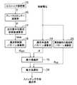
このうち、制限パターン演算部30はインバータ8の出力電流及び車両速度から交流電動機9で発生する電気ブレーキ出力トルクを推定する出力トルク推定部15と、推定した電気ブレーキトルクからブレーキエネルギーを計算するブレーキエネルギー演算部16と、抵抗器5に流すべき平均電流を計算する抵抗器平均電流参照値演算部17と、計算された平均電流参照値からスイッチング手段6の通流率制限パターンを計算する通流率制限パターン演算部18とで構成されている。
【0019】
通流率通常パターン演算部19は架線電圧を入力し、前述した通流率通常パターン21を求めるものであり、最小値選択部20は通流率制限パターン演算部18及び通流率通常パターン演算部19の各出力を入力し、値の小さい一方を選択してスイッチング手段6に対する通流率を出力するものである。なお、図2に示した最小値選択部20及び制限パターン演算部30が本発明の通流率制限手段に対応している。
【0020】
上記のように構成された本実施形態の動作について以下に説明する。先ず、出力トルク推定部15では、インバータ8の出力電流及び車両速度から交流電動機9で発生した電気ブレーキ出力トルクTを計算する。ブレーキエネルギー演算部16は次式によって交流電動機9で発生した電気ブレーキエネルギーPを計算する。
P=T×V …(1)
ただし、
P:電気ブレーキエネルギー[W]
T:電気ブレーキ出力トルク[N]
V:電気車の速度[m/s]
である。
【0021】
抵抗器平均電流参照値演算部17では、ブレーキエネルギー演算部16で計算して得られた電気ブレーキエネルギーPを抵抗器5で全て消費すると仮定した場合、抵抗器5に流すべき平均電流の参照値Iaveを次式によって計算する。
Iave=(P×η×k)/Vfc …(2)
ただし、
Iave:抵抗器5に流すべき平均電流の参照値[A]
η :インバータ効率、交流電動機と車軸との間に介装されたギヤのロス分を総合的に考慮した効率[%]
k :抵抗器5の抵抗値の変動を考慮したマージン[−]
Vfc :架線電圧[V]
である。
【0022】
通流率制限パターン演算部18では、抵抗器平均電流参照値演算部17で計算した平均電流の参照値Iaveからスイッチング手段6の通流率を制限するパターンを次式によって計算する。
αest=Iave/Iins
=Iave/(Vfc/R)…(3)
ただし、
αest :スイッチング手段6の通流率(%)
Iins :抵抗器5に流すことが可能な瞬時電流値[A]
R :抵抗器の抵抗値(定格値)[Ω]
である。
【0023】
一方、通流率通常パターン演算部19は図3の線図で示した通流率通常パターン21に従って、そのときの架線電圧に応じた通流率αを出力する。最小値選択部20は通流率制限パターン演算部18で計算された通流率αestと、通流率通常パターン演算部19から出力される通流率αとを入力し、両者を比較することによって値の小さい一方を選択して出力する。
【0024】
図3は通流率通常パターン演算部19が架線電圧に従って通流率を決定するための通流率通常パターン21と、制限パターン演算部30がインバータの出力電流信号、電気車の速度信号及び架線電圧信号に基づいて演算した通流率制限パターン22とを併せて示した線図である。この図3から明らかなように、架線電圧がVeよりも低い範囲では通流率通常パターン21に従った通流率が採用され、架線電圧がVeよりも高い範囲では通流率制限パターン22に従った通流率が採用される。なお、通流率制限パターン22は交流電動機9で発生する電気ブレーキエネルギー量によって上下に変化する。
【0025】
このように、最小値選択部20によって、スイッチング手段6の通流率を、通流率通常パターン21及び通流率制限パターン22のうちの、値の小さい一方の通電率を選択することによって、交流電動機9で発生する電気ブレーキ以外のエネルギーが、直流架線1から抵抗器5に流れ込むことを防ぐことが可能になる。図4は図2に示した制限パターン演算部30を構成する出力トルク推定部15、ブレーキエネルギー演算部16及び抵抗器平均電流参照値演算部17が、それぞれの演算を実行するための信号入力部を示したブロック図である。ここで、出力トルク推定部15は、図1では図示を省略したインバータ出力電流検出手段26のインバータ出力電流信号Ioutと車両速度検出手段14の速度信号Vとに基づいて、交流電動機9で発生した電気ブレーキ出力トルクTを周知の計算式によって計算する。ブレーキエネルギー演算部16は電気ブレーキ出力トルクTと、車両速度検出手段14の速度信号Vとに基づき、(1)式に従って電気ブレーキエネルギーPを演算する。抵抗器平均電流参照値演算部17は電気ブレーキエネルギーPと架線電圧検出手段13によって検出された架線電圧信号Vfcとに基づき、(2)式に従って抵抗器5に流すべき平均電流の参照値Iaveを計算する。通流率制限パターン演算部18は平均電流の参照値Iaveを入力し、(3)式に従ってスイッチング手段6の通流率αestを計算する。上述したインバータ出力電流検出手段26、車両速度検出手段14及び架線電圧検出手段13は通常、インバータを制御するために設けてあるものであり、これらの制御を実施するための新たな信号検出手段を必要とはしない。
【0026】
かくして、本発明の第1の実施形態によれば、交流電動機9で発生する電気ブレーキエネルギーを推定し、この電気ブレーキエネルギーに応じてスイッチング手段6の通流率に制限をかけるので、入力電流検出手段を設置せずに、架線電圧が高い場合の架線から抵抗器への電流の流れ込みを低減することができ、これによって、抵抗器の省スペース、低コスト化、架線電圧が高い時の電気ブレーキの有効利用を図ることができる。
【0027】
また、本提案による通流率の制限方法は、交流電動機9が発生する電気ブレーキ力に全く影響を与えない。また、ブレーキ抵抗への流入電力が低減されるためブレーキ抵抗の過温度により、電気ブレーキ力自体が制限されることがないため、電気ブレーキを最大限に活用することができ、これにより、長期的には摩擦ブレーキで補足するブレーキ力が低減されることになり、ブレーキシューの摩耗を低減することができるという効果も得られる。
【0028】
図5は本発明に係る電気車制御装置の第2の実施形態の制御部の構成を示すブロック図であり、図中、第1の実施形態を示す図4と同一の要素には同一の符号を付してその説明を省略する。この実施形態は第1の実施形態で用いた車両速度検出手段14を用いないで、その代わりにインバータ出力電流検出手段26の電流検出信号に基づいて、速度推定部27が車両の速度Vを推定するものである。速度推定の手法は近年実用化されている速度センサレス制御に用いられているように、インバータ8の出力周波数を推定し、この出力周波数の値を速度の概算値とする。
【0029】
かくして、本発明の第2の実施形態によれば車両速度検出手段14が不要化される。厳密には交流電動機9として誘導電動機を用いた場合、この誘導電動機にはすべりが存在するため、インバータ周波数とロータ周波数(車両速度相当)は異なるが、本実施形態ではマージンの範囲内と考えられ、第1の実施形態と同様な効果が得られる。
【0030】
図6は本発明に係る電気車制御装置の第3の実施形態の制御部の構成を示すブロック図であり、図中、第1の実施形態を示す図2と同一の要素には同一の符号を付してその説明を省略する。この実施形態は図2に示す構成要素に対して、架線電圧の急峻な変動を検出し、その変動が大きいときにこれを打ち消すように、通流率αdisを急峻に変化させるための通流率演算部23と、この通流率演算部23の出力と最小値選択部20の出力とを比較し、値の大きい一方を選択して出力する最大値選択部24とを新たに付加した点が第1の実施形態と構成を異にしている。なお、急峻な変動とは電圧の時間変化率が所定値を超えることを意味しており、微分手段と比較手段とで実現することができる。
【0031】
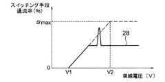
この実施形態によれば、架線電圧が過渡的に急激に上昇した場合には、図7中に通流率部分増大パターン28に従って通流率αdisを求め、通流率制限パターン22を超えて通流率を変化させることができる。
【0032】
この第3の実施形態によれば、第1の実施形態の効果に加えて、通流率の制限中に外乱等により架線電圧が急峻に変動する場合に、通電率の制限範囲を超えて即応性良く架線電圧を制御することができるため、架線が瞬間的に過電圧になることを防止することができるという効果も得られる。
【0033】
図8は本発明に係る電気車制御装置の第4の実施形態の制御部の構成を示すブロック図であり、図中、第3の実施形態を示す図6と同一の要素には同一の符号を付してその説明を省略する。この実施形態は図6中の通流率演算部23に代えて、架線電圧が定格電圧よりも高く設定した制限値を超えて大幅に上昇したとき、通流率制限パターン22に従って制限するのではなく、通流率通常パターン21の許容最大値αmaxに変更する高架線時通流率パターン演算部25を設けた点が図6と構成を異にしており、これ以外は全て図6と同一に構成されている。
【0034】
図9は高架線時通流率パターン演算部25が通流率αupを算出する高架線時通流率パターン29を示し、架線電圧がV2以下の範囲にあるときは通流率制限パターン演算部18の通電率αestと通流率通常パターン演算部19の通電率αのうちいずれか小さい値が採用されるが、架線電圧がV2を超えてからV3に到達するまで次第に増大し、架線電圧がV3を超えた範囲では最大値αmaxになる高架線通電率αupが採用される。
【0035】
この第4の実施形態によれば、外乱等により架線電圧が大幅に上昇するような場合にも、スイッチング手段6による架線電圧抑制機能が働き、架線が過電圧になることを防止することが可能になるという効果も得られる。
【0036】
【発明の効果】
以上の説明によって明らかなように、本発明によれば、入力電流検出手段を設置せずに、架線電圧が高い場合の架線から抵抗器への電流の流れ込みを低減することにより、抵抗器の省スペース、低コスト化、架線電圧が高い時の電気ブレーキの有効利用を図ることのできる電気車制御装置が提供される。
【図面の簡単な説明】
【図1】本発明に係る電気車制御装置の第1の実施形態の主回路構成を示す回路図。
【図2】図1の主回路に対応する制御部のうち、スイッチング手段の制御部の構成を示すブロック図。
【図3】図2に示した制御部の動作を説明するために、架線電圧と通流率との関係を示した線図。
【図4】図2に示す制御部の信号入力部の詳細を示すブロック図。
【図5】本発明に係る電気車制御装置の第2の実施形態のスイッチング手段の制御部の構成を示すブロック図。
【図6】本発明に係る電気車制御装置の第3の実施形態のスイッチング手段の制御部の構成を示すブロック図。
【図7】図6に示した制御部の動作を説明するために、架線電圧と通流率との関係を示した線図。
【図8】本発明に係る電気車制御装置の第4の実施形態のスイッチング手段の制御部の構成を示すブロック図。
【図9】図8に示した制御部の動作を説明するために、架線電圧と通流率との関係を示した線図。
【図10】従来の電気車制御装置の概略を説明するために、その主回路構成を示した回路図。
【符号の説明】
1 直流架線
2 直流電力集電器
5 抵抗器
6 スイッチング手段
8 可変電圧可変周波数インバータ
9 交流電動機
13 架線電圧検出手段
14 車両速度検出手段
15 出力トルク推定部
16 ブレーキエネルギー演算部
17 抵抗器平均電流参照値演算部
18 通流率制限パターン演算部
19 通流率通常パターン演算部
20 最小値選択部
23 通流率演算部
24 最大値選択部
25 高架線時通流率パターン演算部
26 インバータ出力電流検出手段
27 速度推定部
30 制限パターン演算部[0001]
BACKGROUND OF THE INVENTION
The present invention relates to an electric vehicle control device.
[0002]
[Prior art]
A variable voltage variable frequency inverter device (hereinafter simply referred to as an inverter) for supplying electric power to a motor for driving an electric vehicle, switching means between a positive and negative terminals on the DC side of the inverter, and a resistor connected in series to the switching means In the electric vehicle control device having the above, the consumption of electric brake energy in the resistor is controlled by controlling the switching means (see, for example, Patent Document 1).
[0003]
FIG. 10 is a circuit diagram showing a main circuit configuration of this type of electric vehicle control apparatus. In the figure, a positive side of a DC side terminal of an
[0004]
In contrast to the main circuit configuration described above, the control circuit not shown in FIG. The control operation related to the present invention will be described below.
[0005]
The function of controlling the electric brake energy consumption is realized by the
[0006]
FIG. 3 is a diagram showing the relationship between the overhead line voltage (V) and the conduction rate (%). In general, the conduction rate is controlled according to the overhead line voltage as in the
[0007]
In this control method, the switching means is used even when the transmission voltage from the substation to the overhead line is high, when the overhead line voltage is increased by running of another vehicle, or when the electric brake energy generated by the
[0008]
As a countermeasure, as shown in the figure, in a system in which the input current detection means 12 is installed in the power input section from the DC overhead line 1, the input current is monitored by the input current detection means 12, and the DC overhead line is used during the braking operation. When current is flowing from 1 to the electric vehicle control device, control is performed to limit the flow rate of the switching means 6.
[0009]
On the other hand, in a system in which the input current detection means is not installed in the power input section from the DC overhead line 1, a
[0010]
[Patent Document 1]
Japanese Patent Laid-Open No. 05-219605
[Problems to be solved by the invention]
In the method of limiting the conduction rate by installing the input current detection means 12 in the power input section of the electric vehicle control device, a signal input means for inputting the detection signal of the input current detection means 12 and converting it into a predetermined signal is provided. I had to set it up. In addition, when viewed over the long term, maintenance of them was also necessary.
[0012]
On the other hand, when the input current detection means is not used, the
[0013]
Therefore, the temperature rise of the resistor is detected or estimated, and when the temperature exceeds the allowable range, the flow rate of the
[0014]
The present invention has been made in order to solve the above-described problems, and reduces the flow of current from the overhead line to the resistor when the overhead line voltage is high without installing an input current detection unit. An object of the present invention is to provide an electric vehicle control device capable of saving space, reducing costs, and effectively using an electric brake when the overhead wire voltage is high.
[0015]
[Means for Solving the Problems]
The present invention relates to a variable voltage variable frequency inverter device that converts a direct current collected from a DC overhead line into an alternating current and supplies it to an AC motor that drives an electric vehicle, and a positive and negative terminal on the DC side of the variable voltage variable frequency inverter device In the electric vehicle control device comprising a resistor and a switching means connected in series between, and controlling an electric brake energy consumed by the resistor by controlling a flow rate of the switching means, the variable voltage An output torque estimating unit that estimates an electric brake output torque generated by the AC motor from an output current signal of the variable frequency inverter device and a vehicle speed, and brake energy is calculated from the electric brake torque estimated by the output torque estimating unit. Calculated by the brake energy calculation unit and the brake energy calculation unit. Calculated by a resistor average current reference value calculation unit that calculates an average current reference value to be passed through the resistor based on the brake energy and an overhead line voltage signal of the DC overhead line, and a resistor average current reference value calculation unit A conduction rate restriction pattern computing unit that calculates a conduction rate restriction pattern of the switching means from the average current reference value, and a restriction pattern computation unit comprising the overhead line voltage signal and the overhead wire voltage at that time A normal flow rate pattern calculation unit that calculates a normal flow rate pattern according to the flow rate restriction pattern output from the flow rate restriction pattern calculation unit and the normal flow rate pattern output unit. the minimum value selection compared both to input and said duty ratio typically pattern,outputs one small value as the conduction ratio of the selected and the switching means as a minimum value When, is characterized in that at least comprises duty ratio limiting means.
[0016]
DETAILED DESCRIPTION OF THE INVENTION
Hereinafter, the present invention will be described in detail based on preferred embodiments shown in the drawings. FIG. 1 is a circuit diagram showing a main circuit configuration of a first embodiment of an electric vehicle control apparatus according to the present invention. In the figure, the same reference numerals as those in FIG. Indicates an element. In this embodiment, the input current detecting means 12 shown in FIG. 10 is removed.
[0017]
FIG. 2 is a block diagram showing the configuration of the control unit corresponding to the main circuit configuration of FIG. 1, in particular, the part that controls the switching means 6. A
[0018]
Among them, the limit pattern calculation unit 30 is an output
[0019]
The normal ratio normal
[0020]
The operation of the present embodiment configured as described above will be described below. First, the output
P = T × V (1)
However,
P: Electric brake energy [W]
T: Electric brake output torque [N]
V: Speed of electric car [m / s]
It is.
[0021]
In the resistor average current reference
Iave = (P × η × k) / Vfc (2)
However,
Iave: Reference value of the average current to be passed through the resistor 5 [A]
η: Inverter efficiency, efficiency considering overall loss of gears interposed between AC motor and axle [%]
k: Margin [−] in consideration of variation of the resistance value of the
Vfc: overhead wire voltage [V]
It is.
[0022]
The conduction rate limiting
αest = Iave / Iins
= Iave / (Vfc / R) (3)
However,
αest: Flow rate of switching means 6 (%)
Iins: instantaneous current value that can be passed through the resistor 5 [A]
R: Resistance value (rated value) of resistor [Ω]
It is.
[0023]
On the other hand, according to the normal
[0024]
FIG. 3 shows a normal
[0025]
As described above, the minimum
[0026]
Thus, according to the first embodiment of the present invention, the electric brake energy generated in the
[0027]
In addition, the method of limiting the conduction rate according to the present proposal has no influence on the electric brake force generated by the
[0028]
FIG. 5 is a block diagram showing the configuration of the control unit of the second embodiment of the electric vehicle control device according to the present invention. In FIG. 5, the same reference numerals are used for the same elements as those in FIG. The description is omitted. In this embodiment, the vehicle speed detection means 14 used in the first embodiment is not used. Instead, the
[0029]
Thus, according to the second embodiment of the present invention, the vehicle
[0030]
FIG. 6 is a block diagram showing the configuration of the control unit of the third embodiment of the electric vehicle control device according to the present invention. In FIG. 6, the same elements as those in FIG. 2 showing the first embodiment are denoted by the same reference numerals. The description is omitted. This embodiment detects a steep fluctuation of the overhead line voltage with respect to the components shown in FIG. 2, and a conduction ratio for abruptly changing the conduction ratio αdis so as to cancel the fluctuation when the fluctuation is large. Comparing the
[0031]
According to this embodiment, when the overhead line voltage rises transiently and rapidly, the conduction rate αdis is obtained according to the conduction factor
[0032]
According to the third embodiment, in addition to the effect of the first embodiment, when the overhead line voltage fluctuates sharply due to disturbance or the like while the conduction rate is limited, it quickly responds beyond the limitation range of the conduction rate. Since the overhead wire voltage can be controlled with good performance, it is also possible to prevent the overhead wire from instantaneously becoming an overvoltage.
[0033]
FIG. 8 is a block diagram showing the configuration of the control unit of the fourth embodiment of the electric vehicle control device according to the present invention. In FIG. 8, the same elements as those of FIG. 6 showing the third embodiment are denoted by the same reference numerals. The description is omitted. In this embodiment, instead of the conduction
[0034]
FIG. 9 shows a high overhead line
[0035]
According to the fourth embodiment, even when the overhead line voltage increases significantly due to disturbance or the like, the overhead line voltage suppression function by the switching means 6 works, and it is possible to prevent the overhead line from becoming overvoltage. The effect of becoming is also obtained.
[0036]
【The invention's effect】
As is apparent from the above description, according to the present invention, the resistor can be saved by reducing the flow of current from the overhead wire to the resistor when the overhead wire voltage is high, without installing the input current detection means. Provided is an electric vehicle control device capable of effectively using an electric brake when space, cost reduction, and overhead line voltage are high.
[Brief description of the drawings]
FIG. 1 is a circuit diagram showing a main circuit configuration of a first embodiment of an electric vehicle control apparatus according to the present invention.
2 is a block diagram illustrating a configuration of a control unit of a switching unit among control units corresponding to the main circuit of FIG. 1;
FIG. 3 is a diagram showing the relationship between overhead line voltage and conduction rate in order to explain the operation of the control unit shown in FIG. 2;
4 is a block diagram showing details of a signal input unit of the control unit shown in FIG. 2;
FIG. 5 is a block diagram showing a configuration of a control unit of switching means of a second embodiment of the electric vehicle control device according to the present invention.
FIG. 6 is a block diagram showing a configuration of a control unit of switching means of a third embodiment of the electric vehicle control device according to the present invention.
7 is a diagram showing the relationship between overhead line voltage and conduction rate in order to explain the operation of the control unit shown in FIG. 6;
FIG. 8 is a block diagram showing a configuration of a control unit of switching means of a fourth embodiment of the electric vehicle control device according to the present invention.
FIG. 9 is a diagram showing the relationship between overhead line voltage and conduction rate in order to explain the operation of the control unit shown in FIG. 8;
FIG. 10 is a circuit diagram showing a main circuit configuration for explaining an outline of a conventional electric vehicle control device.
[Explanation of symbols]
DESCRIPTION OF SYMBOLS 1 DC
Claims (8)
Translated fromJapanese前記可変電圧可変周波数インバータ装置の出力電流信号及び車両速度から前記交流電動機で発生する電気ブレーキ出力トルクを推定する出力トルク推定部と、前記出力トルク推定部により推定された前記電気ブレーキトルクからブレーキエネルギーを計算するブレーキエネルギー演算部と、前記ブレーキエネルギー演算部により演算された前記ブレーキエネルギーと前記直流架線の架線電圧信号とに基づいて前記抵抗器に流すべき平均電流参照値を計算する抵抗器平均電流参照値演算部と、前記抵抗器平均電流参照値演算部により計算された前記平均電流参照値から前記スイッチング手段の通流率制限パターンを計算する通流率制限パターン演算部と、を備える制限パターン演算部と、
前記架線電圧信号を入力してそのときの架線電圧に応じて通流率通常パターンを演算する通流率通常パターン演算部と、
前記通流率制限パターン演算部から出力された前記通流率制限パターンと前記通流率通常パターン演算部から出力された前記通流率通常パターンとを入力して両者を比較し、値の小さい一方を最小値として選択して前記スイッチング手段の通流率として出力する最小値選択部と、
を少なくとも備える通流率制限手段を有することを特徴とする電気車制御装置。A variable voltage variable frequency inverter device that converts direct current collected from a DC overhead line into alternating current and supplies it to an AC electric motor that drives an electric vehicle, and a positive and negative terminal on the DC side of this variable voltage variable frequency inverter device in series An electric vehicle control device comprising: a connected resistor and switching means; and controlling electric brake energy consumed by the resistor by controlling a flow rate of the switching means.
An output torque estimator for estimating an electric brake output torque generated in the AC motor from an output current signal of the variable voltage variable frequency inverter device and a vehicle speed, and brake energy from the electric brake torque estimated by the output torque estimator A brake energy calculation unit for calculating the average current reference value to be passed through the resistor based on the brake energy calculated by the brake energy calculation unit and the overhead line voltage signal of the DC overhead line A restriction pattern comprising: a reference value calculation unit; and a conduction rate restriction pattern calculation unit that calculates a conduction rate restriction pattern of the switching means from the average current reference value calculated by the resistor average current reference value calculation unit An arithmetic unit;
A continuity ratio normal pattern calculation unit that inputs the trolley voltage signal and calculates a continuity ratio normal pattern according to the overhead line voltage at that time;
The flow rate restriction pattern output from the flow rate restriction pattern calculation unit and the flow rate normal pattern output from the flow rate normal pattern calculation unit are input and compared, and thevalue is small. a minimum value selector that selectsone as the minimum value is output as duty ratio of the switching means,
An electric vehicle control apparatus comprising: a flow rate limiting means including at least
Priority Applications (1)
| Application Number | Priority Date | Filing Date | Title |
|---|---|---|---|
| JP2003158184AJP4316298B2 (en) | 2003-06-03 | 2003-06-03 | Electric vehicle control device |
Applications Claiming Priority (1)
| Application Number | Priority Date | Filing Date | Title |
|---|---|---|---|
| JP2003158184AJP4316298B2 (en) | 2003-06-03 | 2003-06-03 | Electric vehicle control device |
Publications (2)
| Publication Number | Publication Date |
|---|---|
| JP2004364383A JP2004364383A (en) | 2004-12-24 |
| JP4316298B2true JP4316298B2 (en) | 2009-08-19 |
Family
ID=34051681
Family Applications (1)
| Application Number | Title | Priority Date | Filing Date |
|---|---|---|---|
| JP2003158184AExpired - Fee RelatedJP4316298B2 (en) | 2003-06-03 | 2003-06-03 | Electric vehicle control device |
Country Status (1)
| Country | Link |
|---|---|
| JP (1) | JP4316298B2 (en) |
Cited By (1)
| Publication number | Priority date | Publication date | Assignee | Title |
|---|---|---|---|---|
| US7818482B2 (en) | 2004-06-16 | 2010-10-19 | Onkyo Corporation | Amplifier connected to and identifying plurality of content reproducing devices with respective audio speakers |
Families Citing this family (3)
| Publication number | Priority date | Publication date | Assignee | Title |
|---|---|---|---|---|
| JP2007282379A (en)* | 2006-04-06 | 2007-10-25 | Toshiba Corp | Electric car drive |
| JP5580160B2 (en)* | 2010-09-30 | 2014-08-27 | 株式会社東芝 | Electric vehicle control device |
| CN106080215B (en)* | 2016-08-23 | 2019-05-21 | 中车青岛四方机车车辆股份有限公司 | A kind of rail traffic Brake Energy recycling system and hybrid power rail traffic |
- 2003
- 2003-06-03JPJP2003158184Apatent/JP4316298B2/ennot_activeExpired - Fee Related
Cited By (1)
| Publication number | Priority date | Publication date | Assignee | Title |
|---|---|---|---|---|
| US7818482B2 (en) | 2004-06-16 | 2010-10-19 | Onkyo Corporation | Amplifier connected to and identifying plurality of content reproducing devices with respective audio speakers |
Also Published As
| Publication number | Publication date |
|---|---|
| JP2004364383A (en) | 2004-12-24 |
Similar Documents
| Publication | Publication Date | Title |
|---|---|---|
| CN105141193B (en) | Control device of electric motor with least two conductive discharge units | |
| EP2493064B1 (en) | Power converting apparatus for an electric car | |
| JP4778055B2 (en) | Regenerative braking device | |
| JP2015505778A (en) | Method and apparatus for power management of an electric drive of a hybrid vehicle | |
| KR20120037997A (en) | Electric-vehicle propulsion power-conversion device | |
| JP6725298B2 (en) | Electric power conversion control device for trains | |
| JP5902534B2 (en) | Railway vehicle drive system | |
| CA2783782C (en) | Propulsion control apparatus | |
| JP7491361B2 (en) | Power supply device | |
| JP5905166B2 (en) | Electric vehicle control system and power converter | |
| WO2020008575A1 (en) | Control device for railway vehicles and disconnection determination method | |
| JP4316298B2 (en) | Electric vehicle control device | |
| TW202043071A (en) | Power conversion controller | |
| CN111049459B (en) | A braking method for a permanent magnet synchronous motor air conditioner drive device without electrolytic capacitors | |
| JP3413448B2 (en) | Control device for brake chopper | |
| JP2015050779A (en) | Induction motor type electric motor vehicle and control method therefor | |
| KR20120094983A (en) | A multi-parallel energy storage system including multi-phases power converters for regulating the catenary voltage of electric railway | |
| JP5353068B2 (en) | Regenerative power absorber | |
| JP5207908B2 (en) | Electric vehicle control device | |
| CN102372197A (en) | Elevator control device | |
| GB2525279A (en) | Railway vehicle driving device | |
| CN107791843B (en) | A kind of dynamic Control and converting system of electric train | |
| RU2819035C1 (en) | Alternating current electric locomotive fan rpm automated control system | |
| JP5580160B2 (en) | Electric vehicle control device | |
| JPH09121561A (en) | Method of treating regenerative energy of inverter and regenerative energy treating apparatus |
Legal Events
| Date | Code | Title | Description |
|---|---|---|---|
| A621 | Written request for application examination | Free format text:JAPANESE INTERMEDIATE CODE: A621 Effective date:20060111 | |
| A977 | Report on retrieval | Free format text:JAPANESE INTERMEDIATE CODE: A971007 Effective date:20080522 | |
| A131 | Notification of reasons for refusal | Free format text:JAPANESE INTERMEDIATE CODE: A131 Effective date:20080527 | |
| A521 | Written amendment | Free format text:JAPANESE INTERMEDIATE CODE: A523 Effective date:20080709 | |
| A131 | Notification of reasons for refusal | Free format text:JAPANESE INTERMEDIATE CODE: A131 Effective date:20090303 | |
| A521 | Written amendment | Free format text:JAPANESE INTERMEDIATE CODE: A523 Effective date:20090401 | |
| TRDD | Decision of grant or rejection written | ||
| A01 | Written decision to grant a patent or to grant a registration (utility model) | Free format text:JAPANESE INTERMEDIATE CODE: A01 Effective date:20090424 | |
| A01 | Written decision to grant a patent or to grant a registration (utility model) | Free format text:JAPANESE INTERMEDIATE CODE: A01 | |
| A61 | First payment of annual fees (during grant procedure) | Free format text:JAPANESE INTERMEDIATE CODE: A61 Effective date:20090520 | |
| FPAY | Renewal fee payment (event date is renewal date of database) | Free format text:PAYMENT UNTIL: 20120529 Year of fee payment:3 | |
| FPAY | Renewal fee payment (event date is renewal date of database) | Free format text:PAYMENT UNTIL: 20120529 Year of fee payment:3 | |
| FPAY | Renewal fee payment (event date is renewal date of database) | Free format text:PAYMENT UNTIL: 20130529 Year of fee payment:4 | |
| FPAY | Renewal fee payment (event date is renewal date of database) | Free format text:PAYMENT UNTIL: 20130529 Year of fee payment:4 | |
| FPAY | Renewal fee payment (event date is renewal date of database) | Free format text:PAYMENT UNTIL: 20140529 Year of fee payment:5 | |
| LAPS | Cancellation because of no payment of annual fees |