JP4316125B2 - Resin molded body and molding method thereof - Google Patents
Resin molded body and molding method thereofDownload PDFInfo
- Publication number
- JP4316125B2 JP4316125B2JP2000284190AJP2000284190AJP4316125B2JP 4316125 B2JP4316125 B2JP 4316125B2JP 2000284190 AJP2000284190 AJP 2000284190AJP 2000284190 AJP2000284190 AJP 2000284190AJP 4316125 B2JP4316125 B2JP 4316125B2
- Authority
- JP
- Japan
- Prior art keywords
- main body
- fiber
- reinforcing portion
- resin
- resin molded
- Prior art date
- Legal status (The legal status is an assumption and is not a legal conclusion. Google has not performed a legal analysis and makes no representation as to the accuracy of the status listed.)
- Expired - Fee Related
Links
- 229920005989resinPolymers0.000titleclaimsdescription178
- 239000011347resinSubstances0.000titleclaimsdescription178
- 238000000465mouldingMethods0.000titleclaimsdescription54
- 238000000034methodMethods0.000titleclaimsdescription28
- 230000003014reinforcing effectEffects0.000claimsdescription138
- 239000000835fiberSubstances0.000claimsdescription89
- 230000002787reinforcementEffects0.000claimsdescription14
- 238000001746injection mouldingMethods0.000claimsdescription2
- 239000010410layerSubstances0.000description13
- 230000000694effectsEffects0.000description12
- 238000010586diagramMethods0.000description11
- 238000005452bendingMethods0.000description7
- 230000000052comparative effectEffects0.000description4
- 238000004519manufacturing processMethods0.000description4
- 239000003365glass fiberSubstances0.000description3
- 238000005259measurementMethods0.000description3
- 239000004743PolypropyleneSubstances0.000description2
- 238000002347injectionMethods0.000description2
- 239000007924injectionSubstances0.000description2
- 239000000463materialSubstances0.000description2
- -1polypropylenePolymers0.000description2
- 229920001155polypropylenePolymers0.000description2
- 239000002344surface layerSubstances0.000description2
- 229920000049Carbon (fiber)Polymers0.000description1
- 239000004917carbon fiberSubstances0.000description1
- VNWKTOKETHGBQD-UHFFFAOYSA-NmethaneChemical compoundCVNWKTOKETHGBQD-UHFFFAOYSA-N0.000description1
- 229920006122polyamide resinPolymers0.000description1
Images


Landscapes
- Moulds For Moulding Plastics Or The Like (AREA)
- Injection Moulding Of Plastics Or The Like (AREA)
Description
Translated fromJapanese【0001】
【技術分野】
本発明は,本体部と補強部とが一体的に構成された樹脂成形体及びその成形方法に関する。
【0002】
【従来技術】
従来より,図16に示すごとく,本体部91とその表面に一体的に成形された補強部92とを有する樹脂成形体9がある。
上記補強部92は,上記本体部91において曲げ強度や引張り強度等の強度を必要とする方向に沿って,長尺状に形成されている。これにより,上記樹脂成形体9の強度を向上させている。
【0003】
しかし,かかる形状的な補強のみでは,大きな荷重には耐えることが困難である。そこで,上記樹脂成形体9を繊維含有樹脂2により構成することが考えられる。
上記樹脂成形体9を成形するに当っては,上記本体部91用のキャビティと補強部92用のキャビティが一体的に形成された金型を用いる。そして,例えば図16に示す本体部91の端部の一点Gに相当する位置に設けられた上記金型のゲートから,キャビティ内に上記繊維含有樹脂2を射出する。
【0004】
【解決しようとする課題】
しかしながら,上記樹脂成形体9には,以下の問題がある。
即ち,上記のごとく,繊維含有樹脂2を射出しても,該繊維含有樹脂2に含まれる繊維21は,図16に示すごとく配向が揃わない。
それ故,上記補強部92は,長手方向に対する強度が特に向上せず,充分な強度が得られないおそれがある。その結果,上記樹脂成形体9の強度が充分に得られないという問題がある。
【0005】
また,上記補強部を,本体部とは異なる高強度の材料で成形することにより,樹脂成形体の強度を向上させることが考えられる。
しかし,上記樹脂成形体の成形方法は,いわゆる2色成形方法となり,材料費,工数の点で不利である。
【0006】
本発明は,かかる従来の問題点に鑑みてなされたもので,所望の方向に関する強度が大きく,製造容易で安価な樹脂成形体及びその成形方法を提供しようとするものである。
【0007】
【課題の解決手段】
請求項1に記載の発明は,本体部と該本体部の表面に該本体部の長手方向に沿って接合された長尺状の補強部とからなると共に,両者は同じ繊維含有樹脂により一体的に構成されている樹脂成形体を射出成形する方法であって,
上記本体部と上記補強部とは,いずれか一方を先に成形し,次いで他方を成形すると共に金型内において両者を一体的に融着させ,
かつ,上記補強部の成形に当っては,上記本体部の表面に平行な方向で,かつ上記補強部の長手方向に沿って上記繊維含有樹脂が流れるよう,上記繊維含有樹脂を射出することを特徴とする樹脂成形体の成形方法にある。
【0008】
本発明において最も注目すべきことは,上記本体部と該本体部の表面に該本体部の長手方向に沿って接合された長尺状の上記補強部とを,同じ繊維含有樹脂により構成すること,上記本体部と上記補強部のいずれか一方を先に成形し,次いで他方を成形すると共に金型内において両者を一体的に融着させること,及び,上記補強部は,長手方向に沿って繊維含有樹脂が流れるよう,該繊維含有樹脂を射出して成形することである。
【0009】
上記繊維含有樹脂としては,例えば,ガラス繊維,炭素繊維等を含有したポリプロピレン樹脂やポリアミド樹脂がある。また,上記繊維含有樹脂に含まれる繊維は,長繊維であっても短繊維であってもよいが,長繊維であることが,補強部の強度の観点から,より好ましい。
また,上記繊維含有樹脂は,繊維含有量が10〜50重量%であることが好ましい。これにより,確実に補強部の強度を向上させることができる。
【0010】
上記樹脂成形体の成形方法においては,例えば移動型を有する金型を用いる。そして,上記本体部を先に成形する場合には,まず上記金型において,本体部の成形用の第1キャビティを形成しておき,そこへ上記繊維含有樹脂を射出する。次いで,上記金型における移動型を移動させることにより,補強部の成形用の第2キャビティを形成し,そこへ新たに繊維含有樹脂を射出する。
【0011】
次に,本発明の作用効果につき説明する。
上記樹脂成形体の成形方法においては,上記本体部と長尺状の上記補強部を同じ繊維含有樹脂により構成する。そのため,上記樹脂成形体を安価かつ容易に製造することができる。
【0012】
また,上記樹脂成形体を成形するに当っては,上記本体部と上記補強部のいずれか一方を先に成形し,次いで他方を成形し,金型内において両者を融着させる。そのため,長尺状の補強部を成形する際には,上記繊維含有樹脂が,金型における上記本体部を成形するための第1キャビティに流入することはなく,上記補強部を成形するための長尺状の第2キャビティにおいて流動する。それ故,上記繊維含有樹脂の流動方向を制御しやすくなる。
【0013】
そして,上記繊維含有樹脂を射出する際には,補強部の長手方向に沿って繊維含有樹脂が流れるようにする。そのため,繊維含有樹脂に含まれる繊維の多くが,上記本体部の表面に平行な方向で,かつ上記補強部の長手方向に配向する。特に,上記補強部の表層に近い部分において,上記繊維の配向が揃う。
それ故,上記補強部は,長手方向に関して,曲げ強度や引張り強度等の強度を大きくすることができる。その結果,上記樹脂成形体の所望する方向に関する強度を向上させることができる。
【0014】
以上のごとく,本発明によれば,所望の方向に関する強度が大きく,製造容易で安価な樹脂成形体の成形方法を提供することができる。
【0015】
次に,請求項2に記載の発明のように,上記補強部の成形に当っては,該補強部の長手方向の端部に相当する部分から上記繊維含有樹脂を射出することが好ましい。
上記補強部の長手方向の端部に相当する部分とは,金型を用いて上記樹脂成形体を成形する場合,その金型のキャビティにおいて,上記補強部の長手方向の端部が位置する部分をいう。
【0016】
これにより,一層容易かつ確実に,上記補強部を構成する繊維含有樹脂の繊維の配向を,上記補強部の長手方向に沿わせることができる。それ故,一層容易かつ確実に上記補強部の長手方向の強度を大きくし,ひいては上記樹脂成形体の所望の方向に関する強度を大きくすることができる。
【0017】
次に,請求項3に記載の発明のように,上記補強部は,上記本体部よりも先に成形することが好ましい。
これにより,上記本体部と上記補強部との接合を一層強固にすることができる。
【0018】
その理由は次の通りである。上記成形方法によれば,上記補強部がある程度固化した後に,本体部の成型用の繊維含有樹脂を射出することとなる。ここで,上記補強部は,通常,本体部よりも体積が小さい。そのため,ある程度固化した補強部に,本体部の成形用の高温の繊維含有樹脂が接触したとき,接触部分付近における単位体積当りに受熱する熱量が大きく,上記補強部は再溶融しやすい。また,補強部の角部にも高温の繊維含有樹脂が接触するが,該角部は特に単位体積あたりの受熱量が大きく再溶融しやすい。
それ故,本体部と補強部とが一層確実に融着し,両者は強固に接合する。
【0019】
請求項4に記載の発明のように,本体部と該本体部の表面に該本体部の長手方向に沿って接合された長尺状の補強部とからなると共に,両者は互いに融着されて同じ繊維含有樹脂により一体的に構成されている樹脂成形体であって,
上記補強部は,繊維含有樹脂に含まれた繊維が上記補強部の長手方向に沿って配向した配向層を有することを特徴とする樹脂成形体がある。
【0020】
次に,本発明の樹脂成形体の作用効果につき説明する。
上記補強部は,上記のごとく,長尺状の補強部の長手方向に沿って,繊維が配向した配向層を有する。そのため,上記補強部は,長手方向に関して,曲げ強度や引張り強度等の強度が大きい。その結果,上記樹脂成形体の所望する方向に関する強度を向上させることができる。
また,上記樹脂成形体は,上記本体部と上記補強部とを同じ繊維含有樹脂によって構成しているため,容易かつ安価に製造することができる。
【0021】
以上のごとく,本発明によれば,所望の方向に関する強度が大きく,製造容易で安価な樹脂成形体を提供することができる。
【0022】
次に,上記配向層は,上記補強部の表面から0.5mmの厚みの範囲に形成されていることが好ましい。これにより,確実に,所望の方向に関する強度が大きい樹脂成形体を得ることができる。
【0023】
次に,上記配向層の上記繊維は,上記補強部の長手方向の軸線に対する傾斜角度が45°以下のものが,50%以上を占めていることが好ましい。
これにより,所望の方向に関する強度が一層大きい樹脂成形体を得ることができる。
上記傾斜角度45°以下の繊維が50%未満の場合には,補強部の強度が不充分となるおそれがある。
【0024】
【発明の実施の形態】
実施形態例1
本発明の実施形態例にかかる樹脂成形体及びその成形方法につき,図1〜図6を用いて説明する。
本例の樹脂成形体1は,図1に示すごとく,平板状の本体部11と長尺状の補強部12とからなると共に,両者は同じ繊維含有樹脂2により一体的に構成されている。
【0025】
上記補強部12は,図2(A),(B)に示すごとく,繊維含有樹脂2に含まれた繊維21が上記補強部12の長手方向に沿って配向した配向層121を有する。
また,上記配向層121は,図2(A),(B)に示すごとく,上記補強部12の表面122からの厚みdが0.5mmの範囲に形成されている。
【0026】
また,図3に示すごとく,上記配向層121の上記繊維21は,上記補強部12の長手方向の軸線X−Xに対する傾斜角度θが45°以下のものが,約50%を占めている。図3に示す一点鎖線X0−X0は,上記軸線X−Xと平行な線である。
また,図4に示すごとく,上記本体部11と補強部12とは,その界面において融着している。
【0027】
上記繊維含有樹脂2は,ガラス繊維を含有したポリプロピレン樹脂である。即ち,上記繊維21はガラス繊維である。
また,上記繊維含有樹脂2は,繊維含有量が約40重量%である。
【0028】
次に,上記樹脂成形体1の成形方法につき,図5,図6を用いて説明する。
上記樹脂成形体1は,図5に示すごとく,上記本体部11を先に成形し,次いで上記補強部12を成形すると共に両者を融着させる。
上記補強部12の成形に当っては,上記補強部12の長手方向に沿って上記繊維含有樹脂2が流れるよう,該繊維含有樹脂2を射出する。その手段としては,図1に示す上記補強部12の長手方向の端部129に相当する部分から,上記繊維含有樹脂2を射出する。
【0029】
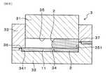
即ち,図6に示すごとく,上記樹脂成形体1を成形するための金型3における,上記補強部の端部129に対応する位置に設けた第2ゲート37から繊維含有樹脂2を射出する。
なお,上記繊維含有樹脂2は,上記補強部12の上部128に相当する部分から射出してもよい。この場合にも,上記繊維含有樹脂2が上記補強部12の長手方向に沿って流れるよう上記繊維含有樹脂2を射出する。
【0030】
上記樹脂成形体1の成形方法においては,図5,図6に示すごとく,移動型31を有する金型3を用いる。即ち,該金型3は,下型32と上型33とを有し,該上型33は,上下にスライド移動可能な上記移動型31を有する。
そして,上記移動型31を最下端に下した状態で,上記下型32と上型33とを組合せることにより,図5(A)に示すごとく,上記本体部11を形成するための第1キャビティ34が形成される。また,この状態から,上記移動型31を上方へスライド移動させることにより,図5(C),図6に示すごとく,上記補強部12を成形するための第2キャビティ35が形成される。
【0031】
また,図6に示すごとく,上記下型32と上型33との間には,外部から上記第1キャビティ34の長手方向の端部341に通じる第1ゲート36と,該第1ゲート36と略反対側であって,上記第2キャビティ35の長手方向の端部351に通じる第2ゲート37が形成されている。
【0032】
上記樹脂成形体1を成形するに当っては,まず,図5(A)に示すごとく,第1キャビティ34を形成しておき,そこへ上記繊維含有樹脂2を上記第1ゲート36から射出する。これにより,図5(B)に示すごとく,第1キャビティ34において,上記本体部11が成形される。
【0033】
次いで,上記第1キャビティ34への繊維含有樹脂2の射出完了の数秒後に,図5(C)に示すごとく,上記移動型31を上方へスライド移動させる。これにより第2キャビティ35を形成し,そこへ新たに繊維含有樹脂2を射出する。
このとき,上記繊維含有樹脂2は,図6に示すごとく,上記第2キャビティ35の長手方向に沿って流れ,該第2キャビティ35を満たす。
これにより,図5(D)に示すごとく,第2キャビティ35において,上記補強部12が形成される。
【0034】
また,このとき,先に成形され,一旦温度が下がってある程度固化した本体部11に,第2キャビティ35に射出された高温の繊維含有樹脂2が接触することにより,接触部分付近が若干溶融する。そして,その溶融部分が,その後,上記第2キャビティ35に射出された繊維含有樹脂2と共に冷却され固化することにより,図4に示すごとく両者は融着する。
以上により,図1に示すような上記樹脂成形体1が一体的に得られる。
【0035】
次に,本例の作用効果につき説明する。
上記樹脂成形体1の成形方法においては,上記本体部11と長尺状の上記補強部12を同じ繊維含有樹脂2により構成する。そのため,上記樹脂成形体1を安価かつ容易に製造することができる。
【0036】
また,上記樹脂成形体1を成形するに当っては,上記本体部11を先に成形し,次いで上記補強部12を成形する。そのため,長尺状の補強部12を成形する際には,上記繊維含有樹脂2が,第1キャビティ34に流入することはなく,長尺状の第2キャビティ35において流動する。それ故,上記繊維含有樹脂2の流動方向を制御しやすくなる。
【0037】
そして,上記繊維含有樹脂2を射出する際には,図6に示すごとく,補強部12の長手方向に沿って繊維含有樹脂2が流れるようにする。そのため,図1,図2(B)に示すごとく,繊維含有樹脂2に含まれる繊維21の多くが,上記補強部12の長手方向に配向する。特に,図2(A),(B)に示すごとく,上記補強部12の表層に近い部分,即ち上記配向層121において,上記繊維21の配向が揃う。
【0038】
即ち,上記補強部12は,長尺状の長手方向に沿って繊維21が配向した配向層121を有する(図2(A),(B))。そのため,上記補強部12は,長手方向に関して,曲げ強度や引張り強度等の強度が大きい。その結果,上記樹脂成形体1の所望する方向に関する強度を向上させることができる。
また,上記配向層121は,図2(A),(B)に示すごとく,上記補強部12の表面122からの厚みdが約0.5mmの範囲に形成されているため,確実に,所望の方向に関する強度が大きい樹脂成形体1を得ることができる。
【0039】
上記配向層121の上記繊維21は,上記補強部12の長手方向の軸線X−Xに対する傾斜角度が45°以下のものが,約50%を占めている。そのため,上記補強部12の長手方向の強度は一層大きく,所望の方向に関する強度が一層大きい樹脂成形体1を得ることができる。
【0040】
以上のごとく,本発明によれば,所望の方向に関する強度が大きく,製造容易で安価な樹脂成形体及びその成形方法を提供することができる。
【0041】
実施形態例2
本例は,図7,図8に示すごとく,補強部12の断面形状を逆T字状とすると共に,該補強部12を本体部11よりも先に成形した樹脂成形体10及びその成形方法の例である。
上記補強部12は,図7に示すごとく,長手方向と垂直な面による断面の形状が逆T字状である。
【0042】
上記樹脂成形体10の成形に当っては,図8に示す金型30を用いる。
該金型30は,下型32と上型33とを有し,上記下型32は,上下にスライド移動可能な移動型31を有する。
上記樹脂成形体10を成形するに当っては,まず,図8(A)に示すごとく,移動型31を上端に配置した状態で,下型32と上型33とを組合せる。これにより,上記補強部12を成形するための第2キャビティ35が形成される。
【0043】
そして,該第2キャビティ35に上記繊維含有樹脂2を射出する(図8(B))。
第2キャビティ35への繊維含有樹脂2の射出完了の数秒後に,上記移動型31を下方へスライド移動させる。これにより,図8(C)に示すごとく,上記本体部11を成形するための第1キャビティ34が形成される。
【0044】
次いで,この第1キャビティ34に,新たに繊維含有樹脂2を射出する。これにより,図8(D)に示すごとく,上記本体部11が成形されると共に,該本体部11は,既に成形されている補強部12とその接触面において融着する。
これにより,図7に示す樹脂成形体10が一体的に成形される。
その他は,実施形態例1と同様である。
【0045】
次に,本例の作用効果につき説明する。
本例の樹脂成形体10は,上述のごとく,補強部12の断面形状が逆T字状である。そして,その底面部124が本体部11と融着する。それ故,上記補強部12と本体部11との界面の面積が大きいため,両者は一層強固に接合する。
【0046】
また,上記補強部12を先に成形し,次いで上記本体部11を成形するため,上記本体部11と上記補強部12との接合を一層強固にすることができる。
その理由は次の通りである。
上記成形方法によれば,上記補強部11がある程度固化した後に,本体部11の成型用の繊維含有樹脂2を射出する。ここで,上記補強部12は本体部11よりも体積が小さい。
【0047】
そのため,ある程度固化した補強部12に,本体部11の成形用の高温の繊維含有樹脂2が接触したとき,接触部分付近における単位体積当りに受熱する熱量が大きく,上記補強部12は再溶融しやすい。また,補強部12の角部123にも高温の繊維含有樹脂2が接触するが,該角部123は特に単位体積あたりの受熱量が大きく再溶融しやすい。
それ故,本体部11と補強部12とが一層確実に融着し,両者は強固に接合する。
その他,実施形態例1と同様の作用効果を有する。
【0048】
実施形態例3
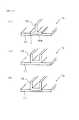
本例は,図9〜図12に示すごとく,補強部12の形状,及び補強部12と本体部11との接合界面の形状を,種々に変化させた樹脂成形体1a〜1kの例である。
以下に,それぞれの形状の特徴と,実施形態例1の樹脂成形体と比較した利点を紹介する。
【0049】
図9(A)に示す樹脂成形体1aは,補強部12の下端部に凸部12aを設け,該凸部12aを本体部11に食い込ませた形状としている。
これにより,上記本体部11と補強部12との接合強度が一層向上する。
【0050】
図9(B)に示す樹脂成形体1bは,補強部12の形状は実施形態例1と同様であるが,その下端部を本体部11に食い込ませた形状である。
この樹脂成形体1bも,上述した樹脂製形体1aと同様に,上記本体部11と補強部12との接合強度が大きい。
【0051】
図9(C)に示す樹脂成形体1cは,補強部12の形状を略正四角柱状とし,その下端部を本体部11に食い込ませた形状である。
この場合には,上記と同様,上記本体部11と補強部12との接合強度が向上するとともに,樹脂成形体1cの小型化,薄型化を図ることもできる。
【0052】
図10(D)に示す樹脂成形体1dは,長尺平板状の補強部12を平板状の本体部11に平行に重ねて接合した形状である。
これにより,補強部12と本体部11との接合面積を大きくし接合強度を大きくすることができると共に,樹脂成形体1dの小型化,薄型化を図ることができる。
【0053】
図10(E)に示す樹脂成形体1eは,上記樹脂成形体1dと同様の補強部12を,同様の向きで,本体部11に食い込ませて接合した形状である。
これにより,上記樹脂成形体1dと同様の作用効果を得る上に,更に本体部11と補強部12との接合強度が大きくなる。
【0054】
図10(F)に示す樹脂成形体1fは,上記樹脂成形体1dと同様の補強部12を,同様の向きで,本体部11に更に深く食い込ませ,本体部11の上面と補強部12の上面とが同一平面となるようにした例である。
これにより,更に本体部11と補強部12との接合強度が大きくなるとともに,補強部12が目立たなくなり,外観性にも優れている。また,樹脂成形体1dの更なる小型化,薄型化を図ることができる。
【0055】
図11(G)に示す樹脂成形体1gは,補強部12を断面円弧状とし,その,左右下端部12gを本体部11に食い込ませた形状である。
これにより,補強部12の強度が向上して,樹脂成形体1gの強度を向上させることができる。また,本体部11と補強部12との接合強度も大きくなる。
【0056】
図11(H)に示す樹脂成形体1hは,上記樹脂成形体1dの形状の補強部12の下端部にギザギザ状部12hを形成した例である。そして,該ギザギザ状部12hを本体部11に食い込ませている。また,上記本体部11における上記補強部12と反対側の面にも,上記ギザギザ状部12hに合わせた形状のギザギザ状部11hを設けている。
これにより,一層,上記本体部11と補強部12との接合強度を大きくすることができる。
【0057】
図12(I)に示す樹脂成形体1iは,実施形態例2と同様の形状の補強部12を,その底面部124を本体部11に食い込ませた例である。
これにより,実施形態例2と同様の作用効果に加え,更に上記本体部11と補強部12との接合強度が大きくなる。
【0058】
図12(J)に示す樹脂成形体1jは,補強部12の断面形状をコ字状とした例である。
これにより,上記補強部12の長手方向の強度が向上し,樹脂成形体1jの強度が向上する。
【0059】
図12(K)に示す樹脂成形体1kは,上記樹脂成形体1jと同様の形状の補強部12を,本体部11に食い込ませた例である。
これにより,上記樹脂成形体1jの有する作用効果に加え,本体部11と補強部12との接合強度が向上する。
【0060】
以上のごとく紹介した樹脂成形体1a〜1kについての他の構成は,実施形態例1と同様である。
また,成形方法については,樹脂成形体1a〜1hは,実施形態例1に示した成形方法であっても,実施形態例2に示す成形方法であってもよい。
ただし,樹脂成形体1i〜1kは,実施形態例2に示す方法で成形する。
また,各樹脂成形体1a〜1kは,上記に紹介した作用効果以外については,実施形態例1又は2と同様の作用効果を有する。
【0061】
実施形態例4
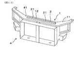
本例は,図13に示すごとく,自動車のフロントエンドモジュールキャリア4に,長尺状の補強部12を形成した例である。
フロンエンドモジュールキャリア4は,ラジエータやコンデンサ等の車両前端部品を組付けて,自動車のフロント部のボディパネルに配設するものである。
【0062】
図13に示すごとく,上記補強部12は,上記フロントエンドモジュールキャリア4の上方側に位置し水平方向に延びる上方側梁部材41の上面に,該上方側梁部材41と一体的に配設されている。即ち,該上方側梁部材41が,本発明における本体部11であり,上記上方側梁部材41と上記補強部12とにより本発明の樹脂成形体1を構成している。
また,上記補強部12の配設方向は,上記上方側梁部材41において負荷のかかり易い方向である左右方向に沿った方向である。
その他は,実施形態例1と同様である。
【0063】
この場合には,負荷のかかり易い左右方向に関して上記上方側梁部材41の強度が向上する。その結果,強度の大きいフロントエンドモジュールキャリア4を得ることができる。
その他,実施形態例1と同様の作用効果を有する。
【0064】
実施形態例5
本例は,図14(A),(B)に示すごとく,樹脂製容器5の開口部51の全周に,補強部11を設けた例である。
この場合には,上記樹脂製容器5における上記補強部12以外の部分が,本発明の本体部11であり,上記補強部12を含めた上記樹脂製容器5が,本発明の樹脂成形体1である。
その他は,実施形態例1と同様である。
【0065】
本例によれば,上記樹脂製容器5の開口部51の強度を向上させることができ,ひいては,強度の大きい樹脂製容器5を得ることができる。
その他,実施形態例1と同様の作用効果を有する。
【0066】
実施形態例6
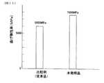
本例は,図15に示すごとく,本発明の樹脂成形体の強度を評価した例である。
即ち,まず,本発明の樹脂成形体として,実施形態例3で示した樹脂成形体1f(図10(F))を成形した。一方,比較例として,従来よりある平板状の樹脂成形体を成形した。
本発明の樹脂成形体と比較例の樹脂成形体との外形は,略同じである。
【0067】
次いで,本発明の樹脂成形体を,補強部が形成されている方向に関して,曲げ弾性率を測定した。
比較例の樹脂成形体についても,同様の測定を行った。
測定結果を図15に示す。
【0068】
同図より分かるように,比較例は,曲げ弾性率が6000MPaであったのに対し,本発明の樹脂成形体の曲げ弾性率は7600MPaであった。即ち,上記補強部を設けることにより,樹脂成形体の曲げ弾性率が,約1.3倍に向上したことが分かる。
【0069】
本例の結果より,本発明の樹脂成形体は,所望の方向,即ち補強部を設ける方向に関する強度が大きいことが分かる。
【図面の簡単な説明】
【図1】実施形態例1における,樹脂成形体の斜視図。
【図2】実施形態例1における,(A)補強部の断面図,(B)(A)のA−A線矢視断面図。
【図3】実施形態例1における,補強部の配向層の繊維の配向状態を表す説明図。
【図4】実施形態例1における,本体部と補強部との界面の説明図。
【図5】実施形態例1における,樹脂成形体の成形方法の説明図。
【図6】実施形態例1における,金型の第2キャビティの長手方向に沿った縦断面説明図。
【図7】実施形態例2における,樹脂成形体の説明図。
【図8】実施形態例2における,樹脂成形体の成形方法の説明図。
【図9】実施形態例3における,補強部の形状及び補強部と本体部の接合界面の形状のバリエーションの説明図。
【図10】実施形態例3における,補強部の形状及び補強部と本体部の接合界面の形状のバリエーションの説明図。
【図11】実施形態例3における,補強部の形状及び補強部と本体部の接合界面の形状のバリエーションの説明図。
【図12】実施形態例3における,補強部の形状及び補強部と本体部の接合界面の形状のバリエーションの説明図。
【図13】実施形態例4における,補強部を設けたフロントエンドモジュールキャリアの斜視図。
【図14】実施形態例5における,補強部を設けた樹脂製容器の斜視図。
【図15】実施形態例6における,樹脂成形体の曲げ弾性率の測定結果を表す線図。
【図16】従来例における,樹脂成形体の斜視図。
【符号の説明】
1,10,1a〜1k...樹脂成形体,
11...本体部,
12...補強部,
121...配向層,
2...繊維含有樹脂,
21...繊維,
3,30...金型,
31...移動型,
32...下型,
33...上型,
34...第1キャビティ,
35...第2キャビティ,[0001]
【Technical field】
The present invention relates to a resin molded body in which a main body portion and a reinforcing portion are integrally formed, and a molding method thereof.
[0002]
[Prior art]
Conventionally, as shown in FIG. 16, there is a resin molded
The reinforcing
[0003]
However, it is difficult to withstand a large load with such geometric reinforcement alone. Therefore, it can be considered that the resin molded
In molding the resin molded
[0004]
[Problems to be solved]
However, the resin molded
That is, as described above, even when the fiber-containing
Therefore, the strength of the reinforcing
[0005]
Further, it is conceivable to improve the strength of the resin molded body by molding the reinforcing portion with a high-strength material different from that of the main body portion.
However, the molding method of the resin molding is a so-called two-color molding method, which is disadvantageous in terms of material costs and man-hours.
[0006]
The present invention has been made in view of such a conventional problem, and an object of the present invention is to provide a resin molded body having a large strength in a desired direction, easy to manufacture and inexpensive, and a molding method thereof.
[0007]
[Means for solving problems]
The invention according to
One of the main body part and the reinforcing part is molded first, and then the other is molded.In the mold BothIntegrally Fused,
And, when molding the reinforcing part,In a direction parallel to the surface of the main body, and In the molding method of the resin molding, the fiber-containing resin is injected so that the fiber-containing resin flows along the longitudinal direction of the reinforcing portion.
[0008]
The most notable aspect of the present invention is that the main body andBonded to the surface of the main body along the longitudinal direction of the main body The long reinforcing partAnd Consists of the same fiber-containing resin, one of the main body and the reinforcing part is molded first, and then the other is moldedAnd fuse them together in the mold The reinforcing part is formed by injecting the fiber-containing resin so that the fiber-containing resin flows along the longitudinal direction.
[0009]
Examples of the fiber-containing resin include polypropylene resin and polyamide resin containing glass fiber, carbon fiber, and the like. The fibers contained in the fiber-containing resin may be long fibers or short fibers, but long fibers are more preferable from the viewpoint of the strength of the reinforcing portion.
The fiber-containing resin preferably has a fiber content of 10 to 50% by weight. Thereby, the intensity | strength of a reinforcement part can be improved reliably.
[0010]
In the molding method of the resin molded body, for example, a mold having a movable mold is used. When the main body is molded first, first, a first cavity for molding the main body is formed in the mold, and the fiber-containing resin is injected into the first cavity. Next, by moving the movable mold in the mold, a second cavity for molding the reinforcing portion is formed, and a fiber-containing resin is newly injected there.
[0011]
Next, the effects of the present invention will be described.
In the molding method of the resin molded body, the main body portion and the elongated reinforcing portion are made of the same fiber-containing resin. Therefore, the resin molded body can be manufactured inexpensively and easily.
[0012]
When molding the resin molded body, either the main body or the reinforcing part is molded first, and then the other is molded.And fuse them together in the mold The Therefore, when the long reinforcing portion is formed, the fiber-containing resin does not flow into the first cavity for forming the main body portion in the mold, and is used for forming the reinforcing portion. It flows in the long second cavity. Therefore, it becomes easy to control the flow direction of the fiber-containing resin.
[0013]
And when inject | pouring the said fiber containing resin, it is made for a fiber containing resin to flow along the longitudinal direction of a reinforcement part. Therefore, many of the fibers contained in the fiber-containing resinIn a direction parallel to the surface of the main body, and Oriented in the longitudinal direction of the reinforcing portion. In particular, the orientation of the fibers is uniform in a portion near the surface layer of the reinforcing portion.
Therefore, the reinforcing portion can increase strength such as bending strength and tensile strength in the longitudinal direction. As a result, the strength of the resin molded body in the desired direction can be improved.
[0014]
As described above, according to the present invention, it is possible to provide a method for molding a resin molded body that has high strength in a desired direction, is easy to manufacture, and is inexpensive.
[0015]
Next, as in the second aspect of the invention, in forming the reinforcing portion, it is preferable to inject the fiber-containing resin from a portion corresponding to an end portion in the longitudinal direction of the reinforcing portion.
The part corresponding to the longitudinal end of the reinforcing part is the part where the longitudinal end of the reinforcing part is located in the mold cavity when the resin molded body is molded using a mold. Say.
[0016]
Thereby, the orientation of the fibers of the fiber-containing resin constituting the reinforcing portion can be more easily and reliably aligned with the longitudinal direction of the reinforcing portion. Therefore, the strength of the reinforcing portion in the longitudinal direction can be increased more easily and reliably, and the strength of the resin molded body in a desired direction can be increased.
[0017]
Next, as in the invention described in
Thereby, joining of the said main-body part and the said reinforcement part can be strengthened further.
[0018]
The reason is as follows. According to the molding method, after the reinforcing part is solidified to some extent, the fiber-containing resin for molding the main body part is injected. Here, the volume of the reinforcing part is usually smaller than that of the main body part. For this reason, when the high-temperature fiber-containing resin for molding the main body part comes into contact with the reinforcing part solidified to some extent, the amount of heat received per unit volume in the vicinity of the contact part is large, and the reinforcing part is easily remelted. Further, although the high-temperature fiber-containing resin is in contact with the corner of the reinforcing portion, the corner has a particularly large heat receiving amount per unit volume and is easily remelted.
Therefore, the main body portion and the reinforcing portion are more securely fused, and both are firmly joined.
[0019]
As in the invention described in claim 4, the main body andBonded to the surface of the main body along the longitudinal direction of the main body It consists of a long reinforcing part and bothFused together A resin molded body integrally formed of the same fiber-containing resin,
The reinforcing part includes a resin molded body having an orientation layer in which fibers contained in a fiber-containing resin are oriented along the longitudinal direction of the reinforcing part.
[0020]
Next, the effect of the resin molding of this invention is demonstrated.
As described above, the reinforcing portion has an alignment layer in which fibers are aligned along the longitudinal direction of the long reinforcing portion. For this reason, the reinforcing portion has high strength such as bending strength and tensile strength in the longitudinal direction. As a result, the strength of the resin molded body in the desired direction can be improved.
Moreover, since the said main body part and the said reinforcement part are comprised with the same fiber containing resin, the said resin molding can be manufactured easily and cheaply.
[0021]
As described above, according to the present invention, it is possible to provide a resin molded body that has high strength in a desired direction, is easy to manufacture, and is inexpensive.
[0022]
next,Up The orientation layer is preferably formed in a thickness range of 0.5 mm from the surface of the reinforcing portion. Thereby, it is possible to reliably obtain a resin molded body having a high strength in a desired direction.
[0023]
next,Up The fibers of the orientation layer preferably occupy 50% or more of those having an inclination angle of 45 ° or less with respect to the longitudinal axis of the reinforcing portion.
As a result, a resin molded body having higher strength in a desired direction can be obtained.
When the fiber having an inclination angle of 45 ° or less is less than 50%, the strength of the reinforcing portion may be insufficient.
[0024]
DETAILED DESCRIPTION OF THE INVENTION
A resin molded body and a molding method thereof according to an embodiment of the present invention will be described with reference to FIGS.
As shown in FIG. 1, the resin molded
[0025]
As shown in FIGS. 2A and 2B, the reinforcing
Further, as shown in FIGS. 2A and 2B, the
[0026]
Further, as shown in FIG. 3, the
As shown in FIG. 4, the
[0027]
The fiber-containing
The fiber-containing
[0028]
Next, a method for molding the resin molded
As shown in FIG. 5, the resin molded
In forming the reinforcing
[0029]
That is, as shown in FIG. 6, the fiber-containing
The fiber-containing
[0030]
In the molding method of the resin molded
Then, by combining the
[0031]
In addition, as shown in FIG. 6, between the
[0032]
In molding the resin molded
[0033]
Next, several seconds after the completion of the injection of the fiber-containing
At this time, the fiber-containing
As a result, the reinforcing
[0034]
At this time, when the high-temperature fiber-containing
Thus, the resin molded
[0035]
Next, the effect of this example will be described.
In the molding method of the resin molded
[0036]
In molding the resin molded
[0037]
And when inject | pouring the said
[0038]
That is, the reinforcing
Further, as shown in FIGS. 2A and 2B, the
[0039]
The
[0040]
As described above, according to the present invention, it is possible to provide a resin molded body that has high strength in a desired direction, is easy to manufacture, and is inexpensive, and a molding method thereof.
[0041]
In this example, as shown in FIGS. 7 and 8, the cross-sectional shape of the reinforcing
As shown in FIG. 7, the reinforcing
[0042]
In molding the resin molded
The
In molding the resin molded
[0043]
Then, the fiber-containing
Several seconds after the completion of the injection of the fiber-containing
[0044]
Next, the fiber-containing
Thereby, the
Others are the same as in the first embodiment.
[0045]
Next, the effect of this example will be described.
In the resin molded
[0046]
Further, since the reinforcing
The reason is as follows.
According to the molding method, after the reinforcing
[0047]
Therefore, when the high-temperature fiber-containing
Therefore, the
In addition, it has the same effects as the first embodiment.
[0048]
This example is an example of the
The features of each shape and the advantages compared with the resin molded body of
[0049]
A resin molded
Thereby, the joint strength between the
[0050]
A resin molded
This resin molded
[0051]
A resin molded body 1 c shown in FIG. 9C has a shape in which the shape of the reinforcing
In this case, as described above, the joint strength between the
[0052]
A resin molded
Thereby, it is possible to increase the bonding area between the reinforcing
[0053]
A resin molded
Thereby, in addition to obtaining the same effect as that of the resin molded
[0054]
The resin molded
This further increases the bonding strength between the
[0055]
A resin molded
Thereby, the intensity | strength of the
[0056]
A resin molded
Thereby, the joint strength of the said main-
[0057]
A resin molded
As a result, in addition to the same effects as those of the second embodiment, the bonding strength between the
[0058]
A resin molded
Thereby, the intensity | strength of the longitudinal direction of the said
[0059]
A resin molded
Thereby, in addition to the effect which the said
[0060]
Other configurations of the resin molded
Regarding the molding method, the resin molded
However, the resin molded
Moreover, each
[0061]
Embodiment 4
In this example, as shown in FIG. 13, a long reinforcing
The front end module carrier 4 is assembled with a vehicle front end part such as a radiator or a condenser and is disposed on the body panel of the front part of the automobile.
[0062]
As shown in FIG. 13, the reinforcing
Further, the direction in which the reinforcing
Others are the same as in the first embodiment.
[0063]
In this case, the strength of the upper
In addition, it has the same effects as the first embodiment.
[0064]
In this example, as shown in FIGS. 14A and 14B, the reinforcing
In this case, the portion other than the reinforcing
Others are the same as in the first embodiment.
[0065]
According to this example, the strength of the
In addition, it has the same effects as the first embodiment.
[0066]
Embodiment 6
In this example, as shown in FIG. 15, the strength of the resin molded body of the present invention was evaluated.
That is, first, as the resin molded body of the present invention, the resin molded
The outer shapes of the resin molded body of the present invention and the resin molded body of the comparative example are substantially the same.
[0067]
Next, the bending elastic modulus of the resin molded body of the present invention was measured in the direction in which the reinforcing portion was formed.
The same measurement was performed for the resin molded body of the comparative example.
The measurement results are shown in FIG.
[0068]
As can be seen from the figure, the comparative example had a flexural modulus of 6000 MPa, whereas the resin molded product of the present invention had a flexural modulus of 7600 MPa. That is, it can be seen that the bending elastic modulus of the resin molded body is improved by about 1.3 times by providing the reinforcing portion.
[0069]
From the result of this example, it can be seen that the resin molded body of the present invention has high strength in a desired direction, that is, a direction in which the reinforcing portion is provided.
[Brief description of the drawings]
FIG. 1 is a perspective view of a resin molded body in a first embodiment.
2A is a cross-sectional view of a reinforcing portion, and FIG. 2B is a cross-sectional view taken along line AA in FIG.
FIG. 3 is an explanatory diagram showing the fiber orientation state of the orientation layer of the reinforcing portion in the first embodiment.
4 is an explanatory diagram of an interface between a main body portion and a reinforcing portion in
FIG. 5 is an explanatory diagram of a method for molding a resin molded body in the first embodiment.
6 is a longitudinal cross-sectional explanatory diagram along the longitudinal direction of the second cavity of the mold in
7 is an explanatory diagram of a resin molded body in
FIG. 8 is an explanatory diagram of a method for molding a resin molded body in the second embodiment.
FIG. 9 is an explanatory diagram of variations of the shape of the reinforcing portion and the shape of the joint interface between the reinforcing portion and the main body portion in the third embodiment.
FIG. 10 is an explanatory diagram of variations of the shape of the reinforcing portion and the shape of the joint interface between the reinforcing portion and the main body in
FIG. 11 is an explanatory diagram of variations in the shape of the reinforcing portion and the shape of the joint interface between the reinforcing portion and the main body in
12 is an explanatory diagram of variations of the shape of the reinforcing portion and the shape of the joint interface between the reinforcing portion and the main body portion in
FIG. 13 is a perspective view of a front-end module carrier provided with a reinforcing portion in Embodiment 4.
14 is a perspective view of a resin container provided with a reinforcing portion in
FIG. 15 is a diagram showing a measurement result of a bending elastic modulus of a resin molded body in Example 6;
FIG. 16 is a perspective view of a resin molded body in a conventional example.
[Explanation of symbols]
1, 10, 1a-1k. . . Resin moldings,
11. . . Body part,
12 . . Reinforcement,
121. . . An alignment layer,
2. . . Fiber-containing resin,
21. . . fiber,
3,30. . . Mold,
31. . . Mobile,
32. . . Lower mold,
33. . . Upper mold,
34. . . First cavity,
35. . . A second cavity,
Claims (4)
Translated fromJapanese上記本体部と上記補強部とは,いずれか一方を先に成形し,次いで他方を成形すると共に金型内において両者を一体的に融着させ,
かつ,上記補強部の成形に当っては,上記本体部の表面に平行な方向で,かつ上記補強部の長手方向に沿って上記繊維含有樹脂が流れるよう,上記繊維含有樹脂を射出することを特徴とする樹脂成形体の成形方法。A resin molded body that is composed of a main body anda long reinforcing partjoined to the surface of the main bodyalong the longitudinal direction of the main body, and both are integrally formed of the same fiber-containing resin. A method of injection molding,
The body part and the reinforcing part are either molded first, then the other is molded and the two areintegrally fused in themold ,
In molding the reinforcing part, the fiber-containing resin is injected so that the fiber-containing resin flows ina direction parallel to the surface of the main body part and along the longitudinal direction of the reinforcing part. A method for molding a resin molded product.
上記補強部は,繊維含有樹脂に含まれた繊維が上記補強部の長手方向に沿って配向した配向層を有することを特徴とする樹脂成形体。The main body part anda long reinforcing partjoined to the surface of the main body partalong the longitudinal direction of the main body part, and both of themare fused together and integrally formed ofthe same fiber-containing resin A resin molded body,
The said reinforcement part has the orientation layer in which the fiber contained in the fiber containing resin orientated along the longitudinal direction of the said reinforcement part, The resin molding characterized by the above-mentioned.
Priority Applications (1)
| Application Number | Priority Date | Filing Date | Title |
|---|---|---|---|
| JP2000284190AJP4316125B2 (en) | 2000-09-19 | 2000-09-19 | Resin molded body and molding method thereof |
Applications Claiming Priority (1)
| Application Number | Priority Date | Filing Date | Title |
|---|---|---|---|
| JP2000284190AJP4316125B2 (en) | 2000-09-19 | 2000-09-19 | Resin molded body and molding method thereof |
Publications (2)
| Publication Number | Publication Date |
|---|---|
| JP2002086493A JP2002086493A (en) | 2002-03-26 |
| JP4316125B2true JP4316125B2 (en) | 2009-08-19 |
Family
ID=18768447
Family Applications (1)
| Application Number | Title | Priority Date | Filing Date |
|---|---|---|---|
| JP2000284190AExpired - Fee RelatedJP4316125B2 (en) | 2000-09-19 | 2000-09-19 | Resin molded body and molding method thereof |
Country Status (1)
| Country | Link |
|---|---|
| JP (1) | JP4316125B2 (en) |
Cited By (1)
| Publication number | Priority date | Publication date | Assignee | Title |
|---|---|---|---|---|
| US7840907B2 (en) | 2006-03-23 | 2010-11-23 | Sony Corporation | Information processing apparatus, information processing method, and program thereof |
Families Citing this family (2)
| Publication number | Priority date | Publication date | Assignee | Title |
|---|---|---|---|---|
| JPWO2011037146A1 (en)* | 2009-09-25 | 2013-02-21 | 東海ゴム工業株式会社 | Resin molding method and resin molded product |
| DE102017127186A1 (en)* | 2017-11-17 | 2019-05-23 | Kunststoff-Fröhlich GmbH | Injection molding apparatus and method |
- 2000
- 2000-09-19JPJP2000284190Apatent/JP4316125B2/ennot_activeExpired - Fee Related
Cited By (1)
| Publication number | Priority date | Publication date | Assignee | Title |
|---|---|---|---|---|
| US7840907B2 (en) | 2006-03-23 | 2010-11-23 | Sony Corporation | Information processing apparatus, information processing method, and program thereof |
Also Published As
| Publication number | Publication date |
|---|---|
| JP2002086493A (en) | 2002-03-26 |
Similar Documents
| Publication | Publication Date | Title |
|---|---|---|
| JP3837025B2 (en) | Hybrid article comprising a rigid part and a part made of thermoplastic material | |
| ES2323064T3 (en) | MANUFACTURING PROCEDURE OF A CAR VEHICLE BODY PART, BODY PIECE. | |
| KR100733134B1 (en) | Frame panel | |
| US8628140B2 (en) | Front end of a motor vehicle | |
| KR20020091276A (en) | Profile composite component and method for the production thereof | |
| JP2001129884A (en) | Composite structural material | |
| US9403319B2 (en) | Reinforced thermoplastic structural joint assembly for a vehicle | |
| US11273872B2 (en) | Vehicle structural component and method for producing a vehicle structural component | |
| CN102452365B (en) | Car neck vent hermetically-sealed construction | |
| CN109080555A (en) | Tape reinforced plastics cladding parts and its manufacturing method | |
| JP4316125B2 (en) | Resin molded body and molding method thereof | |
| CN113895193A (en) | An automobile control arm and automobile | |
| WO2005118345B1 (en) | Structural beam incorporating wire reinforcement | |
| JP4696651B2 (en) | Vehicle pillar structure | |
| KR100978358B1 (en) | Sidebar | |
| US9427931B2 (en) | Production apparatus of skin-fitted foam molding member, production method of skin-fitted foam molding member, and skin-fitted foam molding member | |
| JPWO2013089228A1 (en) | Frame structure and automotive parts using the same | |
| KR102291228B1 (en) | Lightweight integral window channel assembly | |
| JP2000280353A (en) | Synthetic resin-made hollow molded product and its manufacture | |
| CN113508073B (en) | Composite structure and manufacturing method thereof | |
| KR102009793B1 (en) | Seat back frame and method of manufacturing the same | |
| KR101888875B1 (en) | Manufacturing method for car interior part | |
| JP2002283938A (en) | Radiator core support made of synthetic resin and molding method thereof | |
| JP2007069832A (en) | Resin parts for vehicles and manufacturing method thereof | |
| JP2020019242A (en) | Method of manufacturing resin panel for vehicle and resin panel for vehicle |
Legal Events
| Date | Code | Title | Description |
|---|---|---|---|
| A621 | Written request for application examination | Free format text:JAPANESE INTERMEDIATE CODE: A621 Effective date:20061116 | |
| A977 | Report on retrieval | Free format text:JAPANESE INTERMEDIATE CODE: A971007 Effective date:20090129 | |
| A131 | Notification of reasons for refusal | Free format text:JAPANESE INTERMEDIATE CODE: A131 Effective date:20090217 | |
| A521 | Written amendment | Free format text:JAPANESE INTERMEDIATE CODE: A523 Effective date:20090413 | |
| TRDD | Decision of grant or rejection written | ||
| A01 | Written decision to grant a patent or to grant a registration (utility model) | Free format text:JAPANESE INTERMEDIATE CODE: A01 Effective date:20090519 | |
| A01 | Written decision to grant a patent or to grant a registration (utility model) | Free format text:JAPANESE INTERMEDIATE CODE: A01 | |
| A61 | First payment of annual fees (during grant procedure) | Free format text:JAPANESE INTERMEDIATE CODE: A61 Effective date:20090520 | |
| R150 | Certificate of patent or registration of utility model | Free format text:JAPANESE INTERMEDIATE CODE: R150 Ref document number:4316125 Country of ref document:JP Free format text:JAPANESE INTERMEDIATE CODE: R150 | |
| FPAY | Renewal fee payment (event date is renewal date of database) | Free format text:PAYMENT UNTIL: 20120529 Year of fee payment:3 | |
| FPAY | Renewal fee payment (event date is renewal date of database) | Free format text:PAYMENT UNTIL: 20120529 Year of fee payment:3 | |
| FPAY | Renewal fee payment (event date is renewal date of database) | Free format text:PAYMENT UNTIL: 20130529 Year of fee payment:4 | |
| FPAY | Renewal fee payment (event date is renewal date of database) | Free format text:PAYMENT UNTIL: 20140529 Year of fee payment:5 | |
| R250 | Receipt of annual fees | Free format text:JAPANESE INTERMEDIATE CODE: R250 | |
| R250 | Receipt of annual fees | Free format text:JAPANESE INTERMEDIATE CODE: R250 | |
| R250 | Receipt of annual fees | Free format text:JAPANESE INTERMEDIATE CODE: R250 | |
| R250 | Receipt of annual fees | Free format text:JAPANESE INTERMEDIATE CODE: R250 | |
| R250 | Receipt of annual fees | Free format text:JAPANESE INTERMEDIATE CODE: R250 | |
| R250 | Receipt of annual fees | Free format text:JAPANESE INTERMEDIATE CODE: R250 | |
| LAPS | Cancellation because of no payment of annual fees |