JP4315955B2 - Mobile wireless communication device - Google Patents
Mobile wireless communication deviceDownload PDFInfo
- Publication number
- JP4315955B2 JP4315955B2JP2005504582AJP2005504582AJP4315955B2JP 4315955 B2JP4315955 B2JP 4315955B2JP 2005504582 AJP2005504582 AJP 2005504582AJP 2005504582 AJP2005504582 AJP 2005504582AJP 4315955 B2JP4315955 B2JP 4315955B2
- Authority
- JP
- Japan
- Prior art keywords
- cam
- casing
- housing
- degrees
- angle
- Prior art date
- Legal status (The legal status is an assumption and is not a legal conclusion. Google has not performed a legal analysis and makes no representation as to the accuracy of the status listed.)
- Expired - Fee Related
Links
Images


Classifications
- H—ELECTRICITY
- H04—ELECTRIC COMMUNICATION TECHNIQUE
- H04M—TELEPHONIC COMMUNICATION
- H04M1/00—Substation equipment, e.g. for use by subscribers
- H04M1/02—Constructional features of telephone sets
- H04M1/0202—Portable telephone sets, e.g. cordless phones, mobile phones or bar type handsets
- H04M1/0206—Portable telephones comprising a plurality of mechanically joined movable body parts, e.g. hinged housings
- H04M1/0208—Portable telephones comprising a plurality of mechanically joined movable body parts, e.g. hinged housings characterized by the relative motions of the body parts
- H04M1/0214—Foldable telephones, i.e. with body parts pivoting to an open position around an axis parallel to the plane they define in closed position
- H04M1/0216—Foldable in one direction, i.e. using a one degree of freedom hinge
- H—ELECTRICITY
- H01—ELECTRIC ELEMENTS
- H01R—ELECTRICALLY-CONDUCTIVE CONNECTIONS; STRUCTURAL ASSOCIATIONS OF A PLURALITY OF MUTUALLY-INSULATED ELECTRICAL CONNECTING ELEMENTS; COUPLING DEVICES; CURRENT COLLECTORS
- H01R35/00—Flexible or turnable line connectors, i.e. the rotation angle being limited
- H—ELECTRICITY
- H04—ELECTRIC COMMUNICATION TECHNIQUE
- H04M—TELEPHONIC COMMUNICATION
- H04M1/00—Substation equipment, e.g. for use by subscribers
- H04M1/02—Constructional features of telephone sets
- H04M1/0202—Portable telephone sets, e.g. cordless phones, mobile phones or bar type handsets
- H04M1/0206—Portable telephones comprising a plurality of mechanically joined movable body parts, e.g. hinged housings
- H04M1/0208—Portable telephones comprising a plurality of mechanically joined movable body parts, e.g. hinged housings characterized by the relative motions of the body parts
- H04M1/0214—Foldable telephones, i.e. with body parts pivoting to an open position around an axis parallel to the plane they define in closed position
- H04M1/0216—Foldable in one direction, i.e. using a one degree of freedom hinge
- H04M1/0218—The hinge comprising input and/or output user interface means
- E—FIXED CONSTRUCTIONS
- E05—LOCKS; KEYS; WINDOW OR DOOR FITTINGS; SAFES
- E05D—HINGES OR SUSPENSION DEVICES FOR DOORS, WINDOWS OR WINGS
- E05D11/00—Additional features or accessories of hinges
- E05D11/10—Devices for preventing movement between relatively-movable hinge parts
- E05D11/1007—Devices for preventing movement between relatively-movable hinge parts with positive locking
- E—FIXED CONSTRUCTIONS
- E05—LOCKS; KEYS; WINDOW OR DOOR FITTINGS; SAFES
- E05D—HINGES OR SUSPENSION DEVICES FOR DOORS, WINDOWS OR WINGS
- E05D11/00—Additional features or accessories of hinges
- E05D11/10—Devices for preventing movement between relatively-movable hinge parts
- E05D11/1028—Devices for preventing movement between relatively-movable hinge parts for maintaining the hinge in two or more positions, e.g. intermediate or fully open
- E05D11/1078—Devices for preventing movement between relatively-movable hinge parts for maintaining the hinge in two or more positions, e.g. intermediate or fully open the maintaining means acting parallel to the pivot
- E—FIXED CONSTRUCTIONS
- E05—LOCKS; KEYS; WINDOW OR DOOR FITTINGS; SAFES
- E05F—DEVICES FOR MOVING WINGS INTO OPEN OR CLOSED POSITION; CHECKS FOR WINGS; WING FITTINGS NOT OTHERWISE PROVIDED FOR, CONCERNED WITH THE FUNCTIONING OF THE WING
- E05F1/00—Closers or openers for wings, not otherwise provided for in this subclass
- E05F1/08—Closers or openers for wings, not otherwise provided for in this subclass spring-actuated, e.g. for horizontally sliding wings
- E05F1/10—Closers or openers for wings, not otherwise provided for in this subclass spring-actuated, e.g. for horizontally sliding wings for swinging wings, e.g. counterbalance
- E05F1/12—Mechanisms in the shape of hinges or pivots, operated by springs
- E—FIXED CONSTRUCTIONS
- E05—LOCKS; KEYS; WINDOW OR DOOR FITTINGS; SAFES
- E05Y—INDEXING SCHEME ASSOCIATED WITH SUBCLASSES E05D AND E05F, RELATING TO CONSTRUCTION ELEMENTS, ELECTRIC CONTROL, POWER SUPPLY, POWER SIGNAL OR TRANSMISSION, USER INTERFACES, MOUNTING OR COUPLING, DETAILS, ACCESSORIES, AUXILIARY OPERATIONS NOT OTHERWISE PROVIDED FOR, APPLICATION THEREOF
- E05Y2999/00—Subject-matter not otherwise provided for in this subclass
- H—ELECTRICITY
- H01—ELECTRIC ELEMENTS
- H01R—ELECTRICALLY-CONDUCTIVE CONNECTIONS; STRUCTURAL ASSOCIATIONS OF A PLURALITY OF MUTUALLY-INSULATED ELECTRICAL CONNECTING ELEMENTS; COUPLING DEVICES; CURRENT COLLECTORS
- H01R2201/00—Connectors or connections adapted for particular applications
- H01R2201/16—Connectors or connections adapted for particular applications for telephony
- H—ELECTRICITY
- H04—ELECTRIC COMMUNICATION TECHNIQUE
- H04M—TELEPHONIC COMMUNICATION
- H04M2250/00—Details of telephonic subscriber devices
- H04M2250/52—Details of telephonic subscriber devices including functional features of a camera
Landscapes
- Engineering & Computer Science (AREA)
- Signal Processing (AREA)
- Human Computer Interaction (AREA)
- Pivots And Pivotal Connections (AREA)
- Telephone Set Structure (AREA)
- Fluid-Damping Devices (AREA)
Description
Translated fromJapanese 本発明は、一般には、折り畳み式の携帯電話(PDC:パーソナル・ディジタル・セルラー)、パーソナル・ハンディホン・システム(PHS)、その他の移動通信端末(本出願においては、これらを「移動式無線通信装置」と総称する。)に係り、特に、ヒンジ部の内部構造に関する。
技術背景
近年の携帯電話などの移動式無線通信装置の普及に伴い、これらの移動式無線通信装置は単に通信を行えるだけにとどまらず、操作の快適性と安全性の向上、装置の多機能化、装置の小型化など様々な需要がある。
携帯電話には、一般に、折り畳み式の携帯電話と折り畳み式ではない棒状の携帯電話が存在する。このうち、折り畳み式の携帯電話は、典型的には、液晶ディスプレイ(以下、「LCD」という。)画面を含む可動部とテンキーを含む固定部とがヒンジ機構を介して折り畳み可能に構成される。折り畳み式携帯電話の中には、操作の快適性を向上するためにフリーストップ機能、ワンタッチオープン機能、操作の安全性を向上するためにオイルダンパを有するものも既に提案されている(例えば、特許文献1乃至4)。また、装置の多機能化の観点からは、カメラ機能や、インターネットにアクセスしてWeb情報や動画情報をダウンロードするインターネットアクセス機能は既に知られている。
ここで、フリーストップ機能とは、可動部が固定部となす角度を任意の角度に維持することができる機能をいう。ワンタッチオープン機能とは、固定部に設けられた押しボタンを押すことによって可動部が自動的に開口する機能をいう。オイルダンパとは、ヒンジ機構がケース内にオイルを封入し、オイルの粘性を利用して、可動部が開口する際の振動を吸収するダンパである。
Technical background With the spread of mobile wireless communication devices such as mobile phones in recent years, these mobile wireless communication devices are not only able to communicate, but also improve operational comfort and safety, and multifunctional devices. There are various demands such as downsizing of devices.
In general, mobile phones include a foldable mobile phone and a non-foldable stick-like mobile phone. Of these, a foldable mobile phone is typically configured such that a movable part including a liquid crystal display (hereinafter referred to as “LCD”) screen and a fixed part including a numeric keypad can be folded via a hinge mechanism. . Some foldable mobile phones have already been proposed to have a free stop function, a one-touch open function to improve operational comfort, and an oil damper to improve operational safety (for example, patents) References 1 to 4). Further, from the viewpoint of multi-functionality of the apparatus, a camera function and an Internet access function for downloading Web information and moving image information by accessing the Internet are already known.
Here, the free stop function refers to a function capable of maintaining an angle formed by the movable part and the fixed part at an arbitrary angle. The one-touch open function refers to a function in which the movable part automatically opens when a push button provided on the fixed part is pressed. The oil damper is a damper in which a hinge mechanism encloses oil in a case and absorbs vibration when the movable part opens using the viscosity of the oil.
しかし、従来の携帯電話は、通話及び通話以外の機能に対する操作の快適性と安全性を十分に満足していなかった。
例えば、通話操作について、人間工学的には、通話に最適な可動部と固定部の角度は約160度乃至約170度(以下、「通話最適角度」という。)である。可動部と固定部の角度が通話最適角度よりも小さい角度の場合にはユーザは手動で通話最適角度まで広げなければならない。
この点、特許文献2は、その段落番号However, conventional mobile phones have not fully satisfied the comfort and safety of operations for calls and functions other than calls.
For example, regarding the call operation, ergonomically, the angle between the movable portion and the fixed portion that is optimal for a call is about 160 degrees to about 170 degrees (hereinafter referred to as “the optimum call angle”). When the angle between the movable part and the fixed part is smaller than the optimum call angle, the user must manually widen to the optimum call angle.
In this regard,
においてワンタッチオープン機能を利用して「約145度」に開いた状態で通話を行うと記載しているが、実際には、ユーザは手動で通話最適角度まで広げなければならず、2度の開口動作を必要とするため操作性が悪く、通話開始までの時間もかかる。特許文献3も同様に、その段落番号Describes that a call is made with the one-touch open function open at "about 145 degrees", but in practice, the user must manually expand the call to the optimum angle, and open twice. Since operation is required, operability is poor and it takes time to start a call. Similarly, Patent Document 3 has its paragraph number.
及びas well as
に開示しているように、ワンタッチオープン機構により20度までは開口し、その後は、手動で165度まで開かれるため、操作性が悪い。
これに対して、特許文献1及び4は、通話最適角度まで一気に開口可能なワンタッチオープン機能を開示している。しかし、これらのように一気に開口する角度を通話最適角度に設定すると、開口時の反動が大きく、ユーザの手から跳ね飛ぶなど安全性に問題があり、好ましくはない。また、特に、特許文献4は、ワンタッチオープン機構用の押しボタンが、同公報の図11に示すように、可動部についており、固定部が自重で開口するタイプである。ユーザは送信時には固定部を保持して電話番号を入力するのが通常であるため、オープン後に可動部を保持している手を固定部に持ち替えるように構成すると操作性が悪化する。
このように、従来は、操作の快適性と安全性に優れたワンタッチオープン機構が提案されていない。
また、近年のカメラ機能やインターネット機能などの多機能化から、ユーザは、携帯電話を、卓上やその他の場所に所望の開口角度で載置して画像や動画を閲覧したり、所定の開口角度を維持した状態で(即ち、所望のカメラアングルで)撮影したりする需要が出てきた。このため、これらの多機能化に対応してフリーストップ機能を有する必要がある。
以上から、近年の携帯電話の高機能化及び多機能化に対応するためには、通話時には通話最適角度まで安全に開口するワンタッチオープン機能と通話以外の機能に対応したフリーストップ機能を備えた携帯電話を提供する必要がある。また、これらの機能を付加する結果、携帯電話の小型化も維持しなければならない。例えば、特許文献2のように、ワンタッチオープン機構の押しボタンに結合された係止及び係止解除機構を、可動部を固定部から開口するための付勢機構とは別体にして異なる位置に配置すると筐体の大型化をもたらし、好ましくない。
そこで、通話機能及び二次的機能(例えば、カメラ機能)に対する操作の快適性と安全性を向上すると共に小型化にも寄与する移動式無線通信装置を提供することを本発明の例示的な目的とする。
本発明の一側面としての移動式無線通信装置は、入力部を含む第1の筐体と、スピーカーと表示部を含む第2の筐体と、前記第2の筐体を前記第1の筐体に対して折り畳み可能に前記第1の筐体に結合するヒンジ部と、前記第2の筐体を折り畳み状態から前記第1の筐体に対して160度乃至170度の範囲内の第1の角度まで一気に自動的に開口して停止するワンタッチオープン機構と、前記ワンタッチオープン機構による前記第2の筐体の開口動作を制動するダンパ機構と、第2の角度で前記第2の筐体を前記第1の筐体に対して維持するフリーストップ機構とを有することを特徴とする。かかる移動式無線通信装置は、ワンタッチオープン機構が通話最適角度まで第2の筐体を開口するため通話に対する操作性が向上し、ダンパ機構がワンタッチオープン時に開口速度を制動するため、開口動作の安全性が向上している。また、フリーストップ機構が第2の角度(例えば、20度乃至140度、90度乃至140度など)で第2の筐体を固定することができるので通話以外の用途に対する操作性が向上している。
前記フリーストップ機構は、前記第2の筐体を折り畳み状態から前記第1の筐体に対して手動で開口する際に作用するが、前記第1の角度から前記第2の筐体を閉口する際には作用しなくてもよい。代替的に、前記フリーストップ機構は、前記第2の筐体を折り畳み状態から前記第1の筐体に対して手動で開口する際及び、前記第2の筐体を折り畳み状態から前記第1の筐体に対して手動で開口する際に、作用してもよい。
前記第2の筐体が前記第1の筐体に対して第3の角度(例えば、0度乃至20度)をなす場合に、前記第2の筐体を前記第1の筐体に折り畳むように付勢して、前記第2の筐体が前記第1の筐体に対して第4の角度(例えば、140度乃至第1の角度)をなす場合に、前記第2の筐体を前記第1の筐体に対して第1の角度だけ開口するように付勢する付勢機構を更に有してもよい。これにより、ユーザはクリック感を得られると共に第2の筐体の第1の筐体に対するフラツキを防止することができる。前記付勢機構は、例えば、前記第1の筐体に結合された第1のカムと、当該第1のカムに所定の接触力で接触し、前記第2の筐体に結合された第2のカムとを有し、前記第1及び第2のカムの一方は凸部を有し、他方は当該凸部と係合する凹部を有し、前記凸部と前記凹部とは部分的に係合した状態で所定角度だけずれて配置されている。
前記ダンパ機構は前記第2の筐体が前記第1の筐体に対して第5の角度以上となる場合に、制動力を加えるように構成されていてもよい。第5の角度は、例えば、90度である。これにより、制動力を必要な場合にのみ作用させて常に全ての角度範囲で制動力を加えるよりも速やかに第2の筐体を第1の角度だけ開口することができる。
前記ワンタッチオープン機構は、前記第2の筐体を前記第1の筐体から開口する方向に付勢する付勢機構と、前記第2の筐体を前記第1の筐体に折り畳まれた状態で係止する係止機構と、前記係止機構による係止を解除して当該付勢機構による付勢を解放する、前記ヒンジ部又は前記第1の筐体に設けられた押しボタンとを有し、前記付勢機構は、前記第1の筐体に固定されて第1の傾斜面を有する第1のカムと、前記第1のカムの前記第1の傾斜面上で支持され、前記第1の傾斜面に沿って移動及び回転するように付勢された移動部材とを有し、前記係止機構は、前記押しボタンによって係合解除可能に前記第1のカムに係合された係合部材と、前記係合部材に係合し、前記移動部材が前記第1のカムの前記第1の傾斜面に沿って移動することを防止する規制部材とを有し、 当該規制部材は、前記押しボタンが前記係合部材の前記第1のカムに対する係合を解除すると前記前記移動部材と共に回転してもよい。
前記フリーストップ機構は、ある実施形態では、前記第1の筐体に結合された第1の係合部と、当該第1の係合部に所定の接触力で接触し、前記第2の筐体に結合された第2の係合部と、前記第1及び第2の係合部は、前記規制部材が前記移動部材を規制している間は相対的に移動することができることを特徴とする。また、前記規制部材は、前記移動部材が移動可能な第2の傾斜面を有する第2のカムであり、前記係合部材は、前記第2の筐体が前記第1の角度だけ開口すると前記第1のカムと係合し、前記第2の筐体が前記第1の角度だけ開口している状態から第2の筐体を手動で閉口する場合に、前記第1及び第2の係合部が一体的に移動するように前記接触力は調節され、前記移動部材は前記第2のカムの前記第2の傾斜面を移動してもよい。これにより、第2の筐体を第1の角度から手動で戻す際にはフリーストップ機構が働かないように構成することができる。
別の実施形態では、前記規制部材は、前記移動部材が移動可能な傾斜面と平坦面とを有する第2のカムであり、前記フリーストップ機構は、前記第2のカムの前記平坦面に前記移動部材を前記平坦面に抗して移動させる機構を含む。この場合は、第2の筐体を第1の角度から手動で戻す際にもフリーストップ機能が働くことになる。また、前記係合部材は、前記第2の筐体が前記第1の角度だけ開口すると前記第1のカムと係合し、前記第2の筐体が前記第1の角度だけ開口している状態から第2の筐体を手動で閉口する場合、及び、前記第2の筐体が前記第1の筐体に折り畳まれている状態から第2の筐体を手動で開口する場合前記移動部材は前記第2のカムに沿って移動してもよい。これらの場合にフリーストップ機能は作用する。
本発明の他の目的と更なる特徴は、以下、添付図面を参照して説明される実施例において明らかになるであろう。As described in the above, since the one-touch open mechanism opens up to 20 degrees and then manually opens up to 165 degrees, the operability is poor.
On the other hand,
Thus, conventionally, a one-touch open mechanism excellent in operation comfort and safety has not been proposed.
In addition, due to the multi-functionalization of camera functions and Internet functions in recent years, the user can place a mobile phone on a desktop or other place with a desired opening angle to view images and videos, or to have a predetermined opening angle. There has been a demand for shooting in a state where the image is maintained (that is, at a desired camera angle). For this reason, it is necessary to have a free stop function corresponding to these multifunctionalization.
From the above, in order to cope with the recent increase in functionality and multi-functionality of mobile phones, mobile phones equipped with a one-touch open function that opens safely to the optimal angle of call during calls and a free stop function that supports functions other than calls. Need to provide a phone. In addition, as a result of adding these functions, miniaturization of the mobile phone must be maintained. For example, as in
Therefore, an exemplary object of the present invention is to provide a mobile wireless communication device that improves the comfort and safety of operations for a call function and a secondary function (for example, a camera function) and contributes to miniaturization. And
A mobile wireless communication apparatus according to one aspect of the present invention includes a first casing including an input unit, a second casing including a speaker and a display unit, and the second casing including the first casing. A hinge portion coupled to the first housing so as to be foldable with respect to the body, and a first within a range of 160 to 170 degrees with respect to the first housing from the folded state of the second housing. A one-touch open mechanism that automatically opens and stops at an angle to the angle, a damper mechanism that brakes the opening operation of the second casing by the one-touch open mechanism, and the second casing at a second angle. And a free stop mechanism for maintaining the first housing. In such a mobile wireless communication device, the one-touch open mechanism opens the second casing to the optimum call angle, so that the operability for the call is improved, and the damper mechanism brakes the opening speed when the one-touch open, so that the opening operation is safe. Improved. In addition, since the free stop mechanism can fix the second casing at a second angle (for example, 20 degrees to 140 degrees, 90 degrees to 140 degrees, etc.), the operability for applications other than calls is improved. Yes.
The free stop mechanism acts when the second casing is manually opened from the folded state to the first casing, but closes the second casing from the first angle. In some cases, it may not work. Alternatively, the free stop mechanism is configured to manually open the second casing from the folded state to the first casing and when the second casing is folded from the first state. You may act when opening manually with respect to a housing | casing.
When the second casing forms a third angle (for example, 0 degrees to 20 degrees) with respect to the first casing, the second casing is folded to the first casing. When the second casing forms a fourth angle (for example, 140 degrees to the first angle) with respect to the first casing, the second casing is An urging mechanism that urges the first housing so as to open at a first angle may be further included. Thereby, the user can obtain a click feeling and can prevent the second casing from flickering with respect to the first casing. The urging mechanism includes, for example, a first cam coupled to the first casing, a second cam that contacts the first cam with a predetermined contact force, and is coupled to the second casing. One of the first and second cams has a convex portion, the other has a concave portion that engages with the convex portion, and the convex portion and the concave portion are partially related to each other. In a combined state, they are displaced by a predetermined angle.
The damper mechanism may be configured to apply a braking force when the second housing has a fifth angle or more with respect to the first housing. The fifth angle is, for example, 90 degrees. Thus, the second housing can be opened by the first angle more quickly than when the braking force is applied only when necessary and the braking force is always applied in the entire angle range.
The one-touch open mechanism includes a biasing mechanism that biases the second casing in a direction opening from the first casing, and a state in which the second casing is folded into the first casing. And a push button provided on the hinge portion or the first housing that releases the urging by the urging mechanism by releasing the urging by the urging mechanism. The biasing mechanism is supported on the first inclined surface of the first cam fixed to the first housing and having the first inclined surface, and the first cam A moving member biased to move and rotate along one inclined surface, and the locking mechanism is engaged with the first cam so as to be disengaged by the push button. The engaging member engages with the engaging member, and the moving member moves along the first inclined surface of the first cam. And a restricting member for preventing the door, the regulating member, the push button may be rotated together with the moving member and to release the engagement with the first cam of the engagement member.
In one embodiment, the free stop mechanism has a first engagement portion coupled to the first housing, and contacts the first engagement portion with a predetermined contact force. The second engaging portion coupled to the body and the first and second engaging portions can move relatively while the restricting member restricts the moving member. To do. The restricting member is a second cam having a second inclined surface on which the moving member is movable, and the engaging member is formed when the second casing is opened by the first angle. The first and second engagements when the second housing is manually closed from the state where the second cam is engaged with the first cam and the second housing is opened by the first angle. The contact force may be adjusted so that the portion moves integrally, and the moving member may move on the second inclined surface of the second cam. As a result, the free stop mechanism can be configured not to work when the second casing is manually returned from the first angle.
In another embodiment, the restricting member is a second cam having an inclined surface and a flat surface on which the moving member can move, and the free stop mechanism is arranged on the flat surface of the second cam. A mechanism for moving the moving member against the flat surface; In this case, the free stop function also works when the second casing is manually returned from the first angle. The engaging member is engaged with the first cam when the second casing is opened by the first angle, and the second casing is opened by the first angle. When the second casing is manually closed from the state, and when the second casing is manually opened from the state where the second casing is folded into the first casing, the moving member May move along the second cam. In these cases, the free stop function works.
Other objects and further features of the present invention will become apparent from the embodiments described below with reference to the accompanying drawings.
第1図は、本発明の一実施形態の移動式無線通信装置の一例としての携帯電話の平面図である。
第2図は、第1図に示す携帯電話における、三分割構造のヒンジ部の分解平面図である。
第3図は、第2図に示すヒンジ部の分解平面図である。
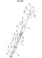
第4図は、第2図に示す携帯電話のヒンジ部に適用可能な機構の一例の構造を示す分解斜視図である。
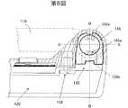
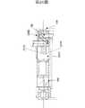
第5図は、ヒンジ部に装着されたブッシュを示す概略断面図である。
第6図は、ブッシュの平面図である。
第7図は、第5図のA−A断面図である。
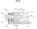
第8図は、第5図のB−B断面図である。
第9図(a)は、第7図に示す押しボタン140を示す断面図であり、第9図(b)は、第8図に示す押しボタン140とその抜け防止機構を示す断面図である。
第10図は、第4図に示すブッシュ及びダンパ機構を省略して組み立てた状態を示す概略斜視図である。
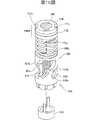
第11図は、第4図に示す外カムと内カムの組み立て状態を示す概略斜視図である。
第12図は、第4図に示す外カムから対向カムまでの別の角度からの分解斜視図である。
第13図(a)及び第13図(b)は、第4図に示すロックが180度回転する様子を説明する概略断面図である。
第14図は、第4図に示す機構の概略分解断面図である。
第15図は、第1図に示す可動側筐体の開口角度の規制機構を説明するための概略断面図である。
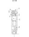
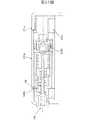
第16図は、第4図に示す機構を組み込んだヒンジ部の概略断面図である。
第17図は、フレキシブルプリント回路基板を第1図に示すヒンジ部に取り付けるための構造を説明するための概略断面図である。
第18図は、第17図の概略断面図である。
第19図は、第4図及び第17図に示すダンパブッシュの変形例を含むヒンジ部の外観断面図である。
第20図は、第19図に示すダンパ及びダンパブッシュの変形例を含むヒンジ部の外観断面図である。
第21図は、第4図に示すダンパブッシュの別の変形例の外観斜視図である。
第22図(a)は第4図に示すダンパの変形例の概略側面図、第22図(b)は第22図(a)に示すダンパの概略正面図、第22図(c)は第21図に示すダンパブッシュの軸の概略正面図、第22図(d)は第21図に示すダンパブッシュの軸の概略側面図、第22図(e)は第22図(a)に示すダンパと第22図(d)に示す軸との接続を説明するための概略斜視図である。
第23図は、ダンパ効果が作用する場合の第22図(a)に示すダンパの軸と第22図(c)に示す軸受け部との関係を示す平面図である。
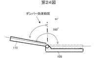
第24図は、第21図乃至第23図に示すダンパ及びダンパブッシュを使用した場合のダンパ効果が作用する範囲を示す概略側面図である。
第25図は、第1図に示す携帯電話のヒンジ部の変形例としての、五分割構造のヒンジ部の分解平面図である。
第26図は、第25図に示す携帯電話のヒンジ部に適用可能な一例の機構の構造を示す分解斜視図である。
第27図は、フレキシブルプリント回路基板を第22図に示すヒンジ部に取り付けるための構造を説明するための概略断面図である。
第28図(a)は第27図に示すダンパ機構の側面図であり、第28図(b)は第27図に示すダンパブッシュの斜視図である。
第29図は、第2図に示す携帯電話のヒンジ部に適用可能な機構の別の例の構造を示す分解斜視図である。
第30図は、第29図に示す機構の概略分解断面図である。
第31図は、第29図に示す機構を組み込んだヒンジ部の概略断面図である。
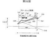
第32図は、第29図に示すワンタッチオープン機構とフリーストップ機構との関係を示すグラフである。
第33図は、第25図に示す携帯電話のヒンジ部に適用可能な別の例の機構の構造を示す分解斜視図である。
第34図は、第15図に示す角度規制機構の変形例を示す概略断面図である。
第35図は、第15図に示す角度規制機構の別の変形例を示す概略断面図である。
第36図は、第35図に示す角度規制機構の具体的な構成例の概略側面図である。
第37図は、第35図に示す角度規制機構の別の具体的な構成例の概略側面図である。
第38図は、第4図又は第26図に示す機構の効果を説明するための概略側面図である。
第39図は、第29図又は第33図に示す機構の効果を説明するための概略側面図である。FIG. 1 is a plan view of a mobile phone as an example of a mobile wireless communication apparatus according to an embodiment of the present invention.
FIG. 2 is an exploded plan view of a hinge portion having a three-part structure in the mobile phone shown in FIG.
FIG. 3 is an exploded plan view of the hinge portion shown in FIG.
FIG. 4 is an exploded perspective view showing a structure of an example of a mechanism applicable to the hinge portion of the mobile phone shown in FIG.
FIG. 5 is a schematic cross-sectional view showing the bush attached to the hinge portion.
FIG. 6 is a plan view of the bush.
FIG. 7 is a cross-sectional view taken along the line AA in FIG.
FIG. 8 is a cross-sectional view taken along the line BB of FIG.
FIG. 9 (a) is a cross-sectional view showing the
FIG. 10 is a schematic perspective view showing a state where the bush and the damper mechanism shown in FIG. 4 are omitted and assembled.
FIG. 11 is a schematic perspective view showing an assembled state of the outer cam and the inner cam shown in FIG.
FIG. 12 is an exploded perspective view from another angle from the outer cam to the opposing cam shown in FIG.
FIGS. 13 (a) and 13 (b) are schematic cross-sectional views illustrating how the lock shown in FIG. 4 rotates 180 degrees.
FIG. 14 is a schematic exploded sectional view of the mechanism shown in FIG.
FIG. 15 is a schematic cross-sectional view for explaining a mechanism for restricting the opening angle of the movable housing shown in FIG.
FIG. 16 is a schematic cross-sectional view of a hinge portion incorporating the mechanism shown in FIG.
FIG. 17 is a schematic cross-sectional view for explaining a structure for attaching the flexible printed circuit board to the hinge portion shown in FIG.
FIG. 18 is a schematic sectional view of FIG.
FIG. 19 is an external cross-sectional view of a hinge portion including a modification of the damper bush shown in FIGS. 4 and 17.
FIG. 20 is an external cross-sectional view of a hinge portion including a modified example of the damper and the damper bush shown in FIG.
FIG. 21 is an external perspective view of another modified example of the damper bush shown in FIG.
FIG. 22 (a) is a schematic side view of a modification of the damper shown in FIG. 4, FIG. 22 (b) is a schematic front view of the damper shown in FIG. 22 (a), and FIG. 21 is a schematic front view of the shaft of the damper bush shown in FIG. 21, FIG. 22 (d) is a schematic side view of the shaft of the damper bush shown in FIG. 21, and FIG. 22 (e) is a damper shown in FIG. It is a schematic perspective view for demonstrating the connection with the axis | shaft shown in FIG.22 (d).
FIG. 23 is a plan view showing the relationship between the shaft of the damper shown in FIG. 22 (a) and the bearing portion shown in FIG. 22 (c) when the damper effect acts.
FIG. 24 is a schematic side view showing a range in which a damper effect acts when the damper and the damper bush shown in FIGS. 21 to 23 are used.
FIG. 25 is an exploded plan view of a hinge part having a five-part structure as a modification of the hinge part of the mobile phone shown in FIG.
FIG. 26 is an exploded perspective view showing the structure of an example of a mechanism applicable to the hinge portion of the mobile phone shown in FIG.
FIG. 27 is a schematic cross-sectional view for explaining a structure for attaching the flexible printed circuit board to the hinge portion shown in FIG.
FIG. 28 (a) is a side view of the damper mechanism shown in FIG. 27, and FIG. 28 (b) is a perspective view of the damper bush shown in FIG.
FIG. 29 is an exploded perspective view showing the structure of another example of a mechanism applicable to the hinge portion of the mobile phone shown in FIG.
FIG. 30 is a schematic exploded sectional view of the mechanism shown in FIG.
FIG. 31 is a schematic sectional view of a hinge portion incorporating the mechanism shown in FIG.
FIG. 32 is a graph showing the relationship between the one-touch open mechanism and the free stop mechanism shown in FIG.
FIG. 33 is an exploded perspective view showing the structure of another example mechanism applicable to the hinge portion of the mobile phone shown in FIG.
FIG. 34 is a schematic sectional view showing a modification of the angle regulating mechanism shown in FIG.
FIG. 35 is a schematic sectional view showing another modified example of the angle regulating mechanism shown in FIG.
FIG. 36 is a schematic side view of a specific configuration example of the angle regulating mechanism shown in FIG. 35.
FIG. 37 is a schematic side view of another specific configuration example of the angle regulating mechanism shown in FIG.
FIG. 38 is a schematic side view for explaining the effect of the mechanism shown in FIG. 4 or FIG.
FIG. 39 is a schematic side view for explaining the effect of the mechanism shown in FIG. 29 or FIG. 33.
以下、添付図面を参照して、本発明の一実施形態の、移動式無線通信装置の一例としての携帯電話100について説明する。ここで、第1図は、携帯電話100の平面図であり、第2図及び第3図は、携帯電話100のヒンジ部130における概略分解平面図である。
第1図に示すように、携帯電話100は、可動側筐体110と、固定側筐体120と、ヒンジ部130と、ワンタッチオープン機構と、ダンパ機構と、フリーストップ機構とを有する。携帯電話100は、可動側筐体110と固定側筐体120とがヒンジ部130により、折り畳み及び展開可能に構成されている、折り畳み式の携帯電話である。
可動側筐体110は、LCD画面112と、スピーカー114と、LED116と、アンテナ118と、レンズ119とを有する。LCD画面112は、日時、発信番号、着信番号、電池残量、受信電界マーク、圏外マーク、各種機能を表示する。スピーカー114は相手の声、各種機能の音声を出力する。LED116は、着信、充電などの携帯電話100の各種ステイタスを表示する。アンテナ118は、伸縮可能で、基地局その他の局と通信を行うのに使用される。レンズ119は、携帯電話にカメラ機能(ビデオカメラ及び/又はスチルカメラ)を持たせるためのもので、第1図に示す可動側筐体110の裏面、その他の面に設けられていてもよい。また、本実施形態の携帯電話100は、アクセスポイントにアクセスしてインターネットを受信することができる。各部112乃至119には当業界で周知のいかなる技術を適用することができるので、ここでは詳しい説明は省略する。
固定側筐体120は、テンキー122と、マイク124とを有する。テンキー122は、相手先の電話番号を入力するためのテンキーの他に、各種記号、アルファベット、ファンクションの入力部(ボタンやコントローラ)、電源オンオフ部などを含むものである。マイク124はユーザからの音声入力を受ける。テンキー122及びマイク124にも当業界で周知のいかなる技術を適用することができるので、ここでは詳しい説明は省略する。
ヒンジ部130は、可動側筐体110を固定側筐体120に対して折り畳み可能に結合し、分割構造を採る。本実施形態のヒンジ部130は、三分割構造を採っているが、後述する五分割構造など、これに限定されるものではない。ヒンジ部130は、第2図及び第3図に示すように、固定側筐体120の両端に形成された一対の凸部131a及び131cと、可動側筐体110に形成され、前記一対の凸部の間に配置される凸部131bから構成される。なお、第2図は、固定側筐体120から分離された可動側筐体110の凸部132における構成を部分的に透過して示しており、第3図は、可動側筐体110の凸部132における構成の概略分解平面図である。
第3図に示すように、凸部131aは中空収納部132aを形成し、凸部131cは中空収納部132cを形成し、凸部131bは、中空収納部132bを形成する。後述する第5図などに示すように、固定側筐体120には固定板133が固定され、固定板133はブッシュ148と係合してブッシュ148を固定する。また、ヒンジ部130の凸部131a及び131cには、後述する第15図に示すように、ストッパー135とネジ136が設けられている。
ヒンジ部130は、ワンタッチオープン機構と、フリーストップ機構と、ダンパ機構200とを収納し、携帯電話100の小型化を図っている。
ワンタッチオープン機構は、ユーザが押しボタン140を押すことによって可動側筐体110を折り畳み状態から固定側筐体120に対して約150度乃至約170度の範囲の角度、例えば、約160度乃至約170度の通話最適角度まで一気に自動的に開口して停止する機構である。なお、本実施形態では、最大開口角度は180度未満であるが、第34図乃至第37図を参照して後述されるように、本発明は最大開口角度を150度乃至170度に制限するものではない。「約150度乃至約170度」としたのは、それがユーザが可動側筐体120を更に開口しなくても通話をすることができる通話可能角度であるからである。また、「約160度乃至約170度」としたのはそれが人間工学的に通話に最適な角度であると共に、本実施形態のワンタッチオープン機構は、0度(即ち、可動側筐体110が固定側筐体120に完全に折り畳まれた状態)から通話最適角度まで一気に可動側筐体110を開口することを目的としているもののその範囲から多少ずれる程度は許容する趣旨である。なお、以下の説明では、便宜上、ワンタッチオープン機構は可動側筐体110を固定側筐体120に対して通話最適角度だけ開口するものとする。
可動部筐体110の最大開口角度は、本実施形態では、通話最適角度に規制されている。かかる角度規制は、第15図に示す、ヒンジ部130の凸部131a及び131cに設けられた、ストッパー135が行う。ストッパー135はネジ136を介して固定側筐体120に固定されている。ここで、第15図は、可動側筐体110の最大開口角度MAを説明するための概略断面図である。ストッパー135は、剛性部材から構成され、可動側筐体110の開口角度が最大開口角度MAになると可動側筐体110の背面と当接してそれ以上の開口を規制する。
なお、本発明は、可動部筐体110の最大開口角度を通話最適角度に限定するものではない。例えば、第34図及び第35図に示す別の角度規制機構を使用することもできる。ここで、第34図及び第35図は第15図に示す角度規制機構の変形例の概略断面図である。第15図に示す角度規制機構においては、ヒンジ部130に負荷が集中し、ヒンジ部130の直交軸の強度以上の負荷が印加されると破損するおそれがあるため、これらの角度規制機構は可動側筐体110が通話最適角度になった後でもそれ以上の角度に変位することを可能にしている。
第34図に示す角度規制機構は、通話最適角度の開口角度を有する可動側筐体110に当接してそれ以上の開口を規制するストッパー137を有し、ストッパー137は軸137a周りに回転可能に構成されている。また、ストッパー137には図示しない捻りコイルバネが設けられ、捻りコイルバネコイルの一端は固定側筐体120に固定され、他端はストッパー137に取り付けられている。この結果、ストッパー137は、第34図において2点鎖線のように変位しても実線で示す位置に復帰するように付勢されている。
同様に、第35図に示す角度規制機構は、第36図に示すように、ストッパー138と、圧縮コイルバネ138bと、一対のボールカム138cと、一対のブロック138dとを有する。ここで、第36図は、第35図に示す角度規制機構の一例の概略側面図である。
ストッパー138は、通話最適角度の開口角度を有する可動側筐体110に当接してそれ以上の開口を規制する。ブロック138は、固定板133に固定され、半球状の溝138eを有する。軸138aは、固定板133に接続されてストッパー138を回転可能に支持する。コイルバネ138bは、ボールカム138cをブロック138dの溝138eに付勢する。ボールカム138cは、ストッパー138を固定板133との間で保持する。ボールカム138cが溝138eに落ち込むとストッパー138をロックする。ストッパー138にヒンジ部130の凸部131bが当接して負荷がかかると、ボールカム138cが溝138eから押し出され、コイルバネ138bの弾性力に抗して移動し、ロックが解除される。ストッパー138が第35図の実線の位置に復帰するとボールカム138cは溝138eに戻ってストッパー138をロックする。一般に、ボールカム138cが脱出するトルクと入るトルクは、脱出するトルク>入るトルクに設定可能であり、戻しは直接ストッパー138を手動で押し戻すトルクに設定することができる。
もちろんカムの形状はボール以外であってもよい。第37図には、断面山形のカム138fと溝138gを有する角度規制機構の例を示す。
この結果、ストッパー138は、第35図において2点鎖線のように変位しても実線で示す位置に復帰するように付勢されている。
フリーストップ機構とは、可動側筐体110が固定側筐体120となす角度を任意の角度(本実施形態では、例示的に、20度から140度)に維持する。フリーストップ機構は、例えば、レンズ119で撮影をしたり、インターネットの情報を卓上で見たりする場合に便宜である。本実施形態では、フリーストップ機構は、ユーザが閉口状態から可動側筐体110を手動で開口した場合に作用し、ワンタッチオープン機構で開口した可動側筐体110をユーザが閉口する場合には作用しない。もっとも、閉口時にフリーストップ機構を作用させないかどうかは選択的である。
本実施形態では、幾つかの部材が、ワンタッチオープン機構とフリーストップ機構を兼ねているために、以下、両者を同時に説明する。このような部材の多機能化によって、本実施形態は、ヒンジ機構130に収納される機構の小型化、ひいては、携帯電話100の小型化を図っている。第2図及び第3図に概略的に示されているヒンジ部130に設けられる機構の分解斜視図を第4図に示す。また、ヒンジ部130に実装された第4図に示す機構の概略断面図を第16図に示す。
第4図に示す機構は、ワンタッチオープン機能のみを働かせる開口動作とフリーストップ機能のみを働かせる開口動作が可能である。また、閉口時にはフリーストップ機能が働かない。このようなワンタッチオープン/フリーストップ機構を本明細書では「ツーウェイ方式」と呼ぶ場合がある。ツーウェイ方式では、ユーザが急いでいる場合や片手が塞がっている場合などに、押しボタン140を左手の親指で押して可動側筐体110を一気に開口する一方、カメラ機能を使用する場合など、微小な角度調節が必要な場合にはユーザは手動で可動側筐体110を開口して任意の角度で停止する。なお、後述するように、本発明は、三分割構造のヒンジ部130に収納される機構をツーウェイ方式に限定するものではない。
第4図を参照するに、ヒンジ部130には、押しボタン140と、圧縮バネ145と、ブッシュ148と、留め輪146と、外カム150と、ロック157と、内カム160と、圧縮バネ165と、対向カム166と、圧縮バネ170と、フリーストップカム172及び176と、軸180と、ダンパ機構200と、キャップ199とを有する。なお、留め輪146から軸180までは第1図乃至第3図においては概略的にヒンジモジュールHMとして示している。
組み立てに際しては、ヒンジ部130の凸部131bを筒状にし、ヒンジモジュールHMを挿入し、ブッシュ148をヒンジモジュールHMと係合させた後でヒンジ部130の凸部131aに押し込んでスナップで固定し、圧縮バネ145を収納した押しボタン140を凸部131aの側面から押し込んでスナップフィットにより固定することによってヒンジ部130の実装を行う。
押しボタン140は、第2図及び第3図には概略的に示されているが、詳細には、第4図及び第9図に示すように、ほぼ中空円筒形状を有する被押圧端部140aと、一対の係合爪142とを有する。ここで、第9図(a)は、押しボタン140を示す断面図であり、第9図(b)は、押しボタン140とその抜け防止機構を示す断面図である。
押しボタン140は、ヒンジ部130から突出し、ユーザがワンタッチオープン時に押圧する部位である。押しボタン140は押圧されると、ロック157と外カム150との係合を解除する。押しボタン140は、本実施形態では、ヒンジ部130の凸部131aに設けられているが、ヒンジ部130から離れた固定側筐体120に設けられてもよい。いずれにしても、押しボタン140は、可動側筐体110(の上部など)にはないので、特許文献4のようにユーザが可動側筐体を保持して筐体を開口した後で可動側筐体を持っていた手を固定側筐体に持ち替える必要はなく操作性は向上している。
被押圧端部140aは、ワンタッチオープン時に典型的にユーザの左手の親指によって押圧力が加えられる部位である。なお、本実施形態は、右利きのユーザが利き腕でメモなどを取りながら逆手で携帯電話100を展開できるように、押しボタン140をヒンジ部130の左側に取り付けているが、左利き用のユーザのために押しボタン140はヒンジ部130の右側に取り付けられてもよい。被押圧部140aは、滑らかに面取りされた円筒又は球面形状を有するが、本発明は、被押圧部140aがその他の曲面形状を有するなど形状を限定するものではない。被押圧端部140aの内部には中空部140bが形成され、第7図に示すように、圧縮バネ145の一端部を収納する。ここで、第7図は、第5図のA−A断面図である。
係合爪142は、それぞれ、第9図(a)に示すように、略直角三角形状を有して被押圧端部140aに対向して設けられ、外カム150の4つの案内溝152の2つと係合する。
押しボタン140の側面には、第9図(b)に示すように、くびれ140cが形成されている。くびれ140cには、固定板133の抜け防止用突起133bが嵌合し、突起133bが壁部140dと係合することによって、圧縮バネ145による圧縮力によって押しボタン140がヒンジ部130から抜け落ちることを防止する。
圧縮バネ145は、押しボタン140を突出方向に付勢する機能を有するコイルバネである。圧縮バネ145の一端部は押しボタン140の中空部140bの端部に当接し、他端部は留め輪146と当接している。
留め輪146は、例示的に、一部が切断されたリング形状又はU字形状を有し、外カム150の固定部151に係合している。留め輪146の外周の形状は第4図に示すように周囲が切り欠かれていてもよいし、円状でもよい。また、留め輪146の切断部は必ずしも必要ではない。但し、周囲の切り欠きや切断部により留め輪146とブッシュ148との機械的な係合を確実にすることができる。留め輪146は中空穴147を有し、中空穴147は、外カム150の凸部153に係合する。留め輪146は、押しボタン140側の面において圧縮バネ145を支持し、その裏面は外カム150の前面151aに載置される。留め輪146は、圧縮バネ145を支持するのに十分であると共に、案内溝152を係合爪142に対して遮蔽しない大きさを有する。
ブッシュ148は、第4図乃至第6図に示すように、長方形と半円を組み合わせたような形状を有し、外カム150を固定する機能を有する。ここで、第5図は、ヒンジ部130に装着されたブッシュ148を示す断面図であり、第6図は、ブッシュ148の平面図である。
ブッシュ148は、その中央に、押しボタン140、外カム150の固定部151及び軸180が挿入可能な中空穴149を形成している。ブッシュ148は、長方形状の支持部148aと、切り欠き部としての係合溝148b及び148cを有し、支持部148aと係合溝148bが固定側筐体120の凸部131aと係合し、係合溝148cは、固定側筐体120にネジ134を介して固定された固定板133の係合部133aと係合する。この結果、ブッシュ148は固定側筐体120の凸部131aに回転不能に固定される。なお、本実施形態のブッシュ148の形状は例示的であり、凸部131aに固定される限り、他の形状を有してもよい。
中空穴149には、外カム150の固定部151が嵌合し、一対の係合部149aを有する。係合部149aは、第8図及び第14図に示すように、外カム150の一対の案内溝152と係合する。この結果、外カム150はブッシュ148に回転不能に固定される。ここで、第8図は、第5図のB−B断面図である。第14図は、第4図に示す機構の概略断面図である。なお、本実施形態では、ブッシュ148が凸状の係合部149aを有して外カム150は案内溝149aを有するが、両者の関係は逆であってもよい。
外カム150は、内カム160と協同して対向カム170を移動させ、ワンタッチオープン機能を実現する機能を有し、固定部151と、本体154とを有する。
固定部151は、第4図において、Y2方向に突出し、断面が略十字形又はX字状の柱形状を有する。固定部151は、中央に略円柱形状の凸部153を有している。凸部153は、Y2方向に突出して留め輪146の中空穴147と嵌合し、固定部151は、前面151aにおいて留め輪146を支持している。前面151aは止め輪146を載置する部分が留め輪146と略同じ大きさの円形又は円形を切り欠いた形状をしている。固定部151は、例えば、円柱を45度間隔で4箇所を円又は楕円によってくり貫くことによって形成され、4つのくり貫かれた部位は案内溝152として外カム150をY方向に貫通している。上述のように、一対の案内溝152は、第8図に示すように、ブッシュ148の係合部149aと係合し、ブッシュ151が固定側筐体120に固定されている結果、外カム150は、回転不能にヒンジ部130に固定される。残りの2つの案内溝152には後述するロック157の腕部158dが挿入されると共に、押し込まれた押しボタン140の係合爪142が挿入可能に構成されている。
本体154は、第11図及び第12図に示すように、一対の山部154a及び154bと、一対の谷部154c及び154dを形成する。山部154a及び谷部154cと山部154b及び谷部154dは対称な形状であってもよいし、異なる形状であってもよい。ここで、第11図は、ロック157が案内溝152に嵌合した状態で内カム160が挿入された外カム150の外観斜視図である。第12図は、外カム150から対向カム166までの別の角度からの分解斜視図である。
ロック157は、押しボタン140の係合爪142と協同して可動側筐体110の固定側筐体120に対する係止及び係止解除を行う機能を有する。ロック157は、円板158aと、一対の肩部158bと、中空穴158cと、一対の腕部158dとを有する。ロック157は、例えば、絶縁加工された金属板から構成される。
円板158aは、圧縮バネ165の一端を支持し、軸180が挿入される中空穴158cを中央に形成している。円板158aは、対称な位置に一対の肩部158bを有する。肩部158bは、円板158aから所定幅で対向する方向に延在し、内カム160の一対の固定溝161aに嵌合する。この結果、ロック157と内カム160とは一体的に動作する。
一対の腕部158dは、それぞれ肩部158bを90度Y2方向に折り曲げることによって形成され、外カム150の一対の案内溝152に挿入される。第12図及び第13図に示すように、各腕部158dの先端は面取り部158eが形成されている。ここで、第13図(a)及び第13図(b)は、ロックが180度回転する様子を説明する概略断面図である。
上述したように、可動側筐体110は、ストッパー135によって最大開口角度MAが通話最適角度に設定されているので、可動側筐体110が160度開口するとロック157もまず160度回転する。この状態では、第13図(b)に示すように、ロック157の各腕部158dは、その面取り部158eが外カム150の案内溝152(可動側筐体110が開口する前の案内溝152に対して180度回転した位置にある案内溝152)の縁部に当接した状態にある。しかし、ロック157は、バネ165によって外カム150側に付勢されているので、面取り部158eが案内溝152に進入していき、かかる進入は20度分の回転角度に相当する。即ち、第13図(a)に矢印で示すように、ロック157は可動側筐体110が160度開口すると20度分だけ更に回転し、腕部158dは外カム150の案内溝152に嵌合する。このように、押しボタン140が押圧されると可動側筐体110は約160度開口するが、ロック157は180度回転して再び案内溝152に係合する。但し、その場合に、各腕部158dが挿入される案内溝152の位置は180度変わっている。
内カム160は、外カム150の中に挿入され、対向カム166の移動及び回転を許容する。第12図に示すように、内カム160は、一対の山部162a及び162bと、一対の谷部162c及び162dとを有する。第11図に示すように、内カム160が外カム150の中に挿入されてロック157の腕部158dが外カム150の案内溝152に挿入されると、外カム150の山部154aと内カム160の山部162aとの間、外カム150の山部154bと内カム160の山部162bとの間に小さな谷が形成される。外カム150がブッシュ148に固定されてロック157が外カム150に固定されているため、内カム160は固定されている。このため、押しボタン140が押される前の状態では、内カム160の山部162a及び162bは、対向カム166の一対の凸部167a及び167bが小さな谷を越えて外カム150の谷部154c及び154dまで滑り落ちることを防止する。本実施形態では、内カム160は、ロック157が180度回転すると外カム150に対して、可動側筐体110の開口角度が0度のときと同様の状態を示す。
圧縮バネ165は、一端がロック157の円板158に当接し、他端が対向カム166の基部167cに当接し、ロック157の腕部158dを外カム150の案内溝152に付勢する機能を有する。
対向カム166は、外カム150及び内カム160に対して移動及び回転することによって可動側筐体110を固定側筐体120に対して通話最適角度だけ開口する機能を有する。ロック157及び内カム160は、可動側筐体110が、例えば、160度開口すると180度開口するが、対向カム166は、外カム150の傾斜面を谷部154c及び154dまで単に滑り落ちるだけであり、その回転角度は160度である。対向カム166は、一対の凸部167a及び167bと、基部167cと、胴部168aと、一対の脚部168bとを有する。なお、凸部167a及び167bは同一形状であってもよいし、異なる形状であってもよい。
押しボタン140が押される前は、第10図に示すように、凸部167aは外カム150の山部154a近傍に載置され、凸部167bは外カム150の山部154b近傍に載置される。ここで、第10図は、ブッシュ148を省略した押しボタン140からフリーストップカム176までの組み立て状態を示す概略斜視図である。この状態では、第11図を参照して上述したように、内カム160の山部162a及び162bにより、凸部167a及び167bは外カム150の傾斜面に沿って移動することが防止される。
基部167cは中央に中空部167dを有する円板形状を有して圧縮バネ165の他端を支持する。胴部168aは、中空円筒形状を有して基部167cの裏面に固定されている。一対の脚部168bは、第10図に示すように、凸部167a及び167bが外カム150の山部154a及び154b近傍にあるときと谷部154c及び154d近傍にあるときに、フリーストップカム172の腕部173bと係合するように、(即ち、分離しないように)長さが設定される。
圧縮バネ170は、対向カム166とフリーストップカム172の間であって胴部168a及び脚部168bとフリーストップカム172の腕部173bの周りに設けられ、対向カム166をY2方向に、フリーストップカム172をY1方向に付勢する。このように、本実施形態では、圧縮バネ145、165、170のみを使用し、ねじりバネを使用していない。可動側筐体110は、バネのねじり力によって開口するのではなく、対向カム166の移動及び回転によって回転する。
フリーストップカム172及び176は、幾つかの機能を有する。第1に、フリーストップカム172及び176は、対向カム166と協同してワンタッチオープン機能を補助する。第2に、フリーストップカム172及び176はフリーストップ機能を発揮する。第3に、フリーストップカム172及び176は、可動側筐体110の固定側筐体120に対する開口角度が0度から20度の場合には0度になるように可動側筐体110を付勢し、開口角度が140度から160度の場合には160度になるように可動側筐体110を付勢する。このような多機能化によって、本実施形態は、ヒンジ部130、ひいては携帯電話100は小型化を実現している。
第4図及び第14図に示すように、フリーストップカム172は、中空部173cを有する円板形状の基部173aと、基部173aからY2方向に対称に延在する一対の腕部173bと、基部173aからY1方向に対称に配置された一対の半球状突起173dとを有する。外カム150からフリーストップカム176までは、ヒンジ部130の可動側筐体110側の凸部131bに設けられている。
フリーストップカム176は、円板状の基部177から構成され、基部177は、中空部177aと、一対の半球状のディンプル177bと、固定部177cとを有する。ディンプル177bは基部177の表面に設けられ、固定部177cは基部177の裏面に設けられている。
フリーストップカム172の一対の腕部173bは、対向カム166の脚部168bと係合可能に構成されている。即ち、第10図に示すように、対向カム166の凸部167a及び167bが外カム150と内カム160の山部の間の小さな谷にあるときと谷部154c及び154dにあるときに、腕部173bは脚部168bと係合するように(即ち、分離しないように)、腕部173bの長さは設定されている。腕部173bと脚部168bとの係合は解除される状態では対向カム166に加えられた回転力はフリーストップカム172に伝達しない。
フリーストップカム172の一対の突起173dは、フリーストップカム176の一対のディンプル177bとある角度範囲で係合可能に構成されている。本実施形態では、かかる角度範囲は約30度である。第14図において、フリーストップカム172と176が相対的に捩れた場合、捩れ角が約30度以内であれば突起173dはディンプル177bの範囲内にある。突起173dは、ディンプル177bの範囲内にあれば、圧縮バネ170による弾性力により、突起173dとディンプル177bの間には角度ズレを戻そうとする力が働く。このため、捩れ角が約30度以内であればフリーストップカム172及び176は捩れを元に戻そうとする力が作用する。これが上述の第3の機能である。第3の機能は、いわゆるクリック感を得るため、固定側筐体120を振ったときに可動側筐体110がふらつかないなどの長所を有する。クリック感とは、ユーザが可動側筐体110の開口角度を0度又は約160度にした場合に当該角度を得たことを実感できるという感触である。
可動側筐体110の開口角度が0度の場合には、突起173dとディンプル177bとの角度ズレは10度に設定されており、可動側筐体110の開口角度が20度の場合には、両者の角度ズレは30度になる。従って、可動側筐体110の開口角度が0度乃至20度の場合には、可動側筐体110には閉口力が働く。
一方、可動側筐体110が約160度開口すると対向カム166はフリーストップカム172と共に160度回転する。このため、フリーストップカム172の突起173dも160度回転する。従って、可動側筐体110の開口角度が140度の場合には、突起173dと反対側のディンプル177bとの角度ズレは30度になり、可動側筐体110の開口角度が160度の場合には、両者の角度ズレは10度になる。従って、可動側筐体110の開口角度が140度乃至160度の場合には、可動側筐体110には開口力が働く。
フリーストップカム176の固定部177cは、第10図に示すように、一対のキー溝として構成され、ここにヒンジ部130の凸部131bに設けられた図示しない凸部が嵌合して固定される。このため、フリーカムストップカム176は、凸部131bと共に回転する。
押しボタン140が押されると対向カム166が移動及び回転し、対向カム166とフリーストップカム172とは脚部168b及び腕部173bを介して係合しているので、フリーストップカム172は対向カム166と共に回転する。このとき対向カム166の凸部167bは、第11図においては、矢印に沿って傾斜面S2を下降する。また、フリーストップカム172と176は係合しているので、かかる回転力はフリーストップカム176に伝達される。この結果、フリーストップカム176が可動側筐体110と共に回転する。即ち、フリーストップカム172及び176は共に回転する。これが上述した第1の機能である。
押しボタン140が押されない状態で、可動側筐体110が手動で開口されると、内カム160が回転しないことにより、対向カム166は、第10図に示す位置で固定(ロック)されている。従って、対向カム166とそれと係合するフリーストップカム172は、可動側筐体110が開口しても静止している。一方、フリーストップカム176は、可動側筐体110の凸部113bと共に回転する。
従って、可動側筐体110の開口角度が20度から140度の間では、フリーストップカム172の突起173dは、フリーストップカム176のディンプル177bから外れて基部177の表面を移動する。なお、これはフリーストップカム176から見た相対的移動であり、実際には、移動しているのはフリーストップカム176である。この際、圧縮バネ170がフリーストップカム172をフリーストップカム176に対して押圧しているので、かかる押圧力又は接触力によってフリーストップカム176はフリーストップカム172に対して任意の角度で固定される。これが上述した第2の機能である。
押しボタン140が押圧されて可動側筐体110が通話最適角度になっている状態から可動側筐体110を手動で閉口する場合について考える。まず、押しボタン140が押圧されて可動側筐体110が通話最適角度になっている状態では、第10図において、対向カム166の凸部167a及び167bは外カム150の谷部154c及び154d上にある。この状態でも、脚部168bは、腕部173bと係合している。また、ロック157は180度回転して再び外カム150に係合しており、内カム160はロックされている。
この状態で、可動側筐体110が手動で閉口されると、フリーストップカム176が凸部131bと共に回転する。フリーストップカム172はフリーストップカム176と共に回転し、フリーストップ機能は働かない。回転力は腕部173dと脚部168bを介して対向カム166に伝達される。内カム160は回転せず、対向カム166の凸部167a及び167bは内カム160の傾斜面を上る。例えば、第11図においては、対向カム166の凸部167bは矢印に沿って内カムの傾斜面S4を上る。このように、ワンタッチオープン時には対向カム166は外カム150の傾斜面を下降するが、その後に、手動で可動側筐体110を閉口すると内カム160の傾斜面を上昇して、第10図に示す状態に復帰する。
軸180は、フリーストップカム176の中空部177a、フリーストップカム172の中空部173c、一対の腕部173bの間、対向カム166の一対の脚部168bの間、中空部167d、内カム160の中空部161b、ロック157の中空部158cを貫通し、ロック157からフリーストップカム176までの回動を容易にする。軸180は、ストッパー182を有してフリーストップカム176に係合するため、軸180とフリーストップカム176とは一体的に回転する。
キャップ199は、第2図乃至第4図に示すように、円板形状を有し、第4図に示す機構を外部から遮蔽している。もっとも、かかる遮蔽機能を達成することができる限り、キャップ199は、第2図及び第3図に示すような凸形状を有していてもよい。
ダンパ機構200は、ワンタッチオープン時に可動側筐体110の開口を制動する機能を有し、ダンパ210とダンパブッシュ230とを有する。ダンパ機構200により、可動側筐体110を通話最適角度まで一気に開口しても開口の反動で携帯電話100がユーザの手から撥ね飛ぶおそれがなくなり、安全性が向上する。ダンパ210は、ヒンジ部130の可動側筐体110側の凸部131bに設けられており、軸180とは接続されていない。ダンパブッシュ230は、ヒンジ部130の固定側筐体120側の凸部131cに設けられている。なお、ダンパ210とダンパブッシュ230の配置は、後述するFPCB102の配置に支障がない限り、逆になっていてもよい。
ダンパ210は、本実施形態ではオイルダンパを使用しているが、本発明はダンパの種類を限定するものではない。また、本実施形態で説明するオイルダンパは、当業界で周知の他の構造をも使用することができる。第14図に示すように、ダンパ210は、略円筒形の筐体211と、筐体211に回転可能に収納された正方形形状の軸214と、当該軸214に結合された中空円筒形状の攪拌部216と、オーリング218とを有し、第14図においてハッチングした部分にはシリコンオイルOが充填されている。オーリング218は、オイルOをシールしたまま攪拌部216がオイルOを攪拌することを可能にしている。筺体211は、可動側筐体110と係合部212において係合している。
ダンパブッシュ230は、軸212と係合する正方形形状の軸受部234を先端に有する軸232を有している。軸212及び軸受部234は、それらが係合する限り、それらの形状は正方形形状に限定されず、これは以下の変形例においても当てはまる。ダンパ210の軸214はダンパブッシュ230によって固定されているので、可動側筐体110が開口すると筐体211が可動側筐体110と共に回転し、攪拌部216と筐体211との相対的な回転により、筐体211はオイルOの粘性抵抗から制動力を受ける。オイルダンパ160は、攪拌部216がオイルOを攪拌することによってダンパ機能を実現する。攪拌部216は、羽根状回転子を有するなど当業界で周知の構造を使用することができる。
可動側筐体110、固定側筐体120、ヒンジ部130には、フレキシブルプリント回路基板(以下、「FPCB(Flexible Printed Circuit Board)」ともいう。)102と、FPCB102に取り付けられたFPCB102にオーバーラップするアンテナの同軸ケーブルや電源ケーブル等のFPCB以外のケーブル(以下、「NFPCB(Non−FPCB)」ともいう。)が捻られた状態で収納されている。FPCB102を捻るのは、FPCB102に弾性力を持たせて開閉時のFPCB102に加わる負荷を低減すると共に開口方向に付勢力を持たせて開口を容易にするためである。本実施形態では、FPCB102とNFPCBを接続して一体としてヒンジ部130を通しているが、両者は独立してヒンジ部130を通されてもよい。
FPCB102は、可動側筐体110に収納されたLCD画面112用の図示しない基板と、固定側筐体120に収納されたテンキー122用の図示しない基板とを接続する。FPCB102は、複数の並列に配置された信号線を絶縁弾性材料でコーティングした構造を有する。信号線や絶縁弾性材料には当業界で周知のいかなる技術をも適用することができるので、ここでは詳しい説明は省略する。NFPCは、アンテナ118に接続された同軸ケーブルや電源ケーブルを含む。本実施形態は、第17図に示すように、ダンパ210の軸214と、ダンパブッシュ230の軸受部232の周りにFPCB102を巻き付けて安定している。ここで、第17図は、FPCB102の取付を説明するためのヒンジ部130の概略断面図である。また、第18図に、FPCB102が可動側筐体110から固定側筐体120に引き出される位置を示す。
第17図に示すダンパブッシュ230はフォーク形状の断面を例示的に有しているが、中空筒形状(例えば、中空円筒、中空角柱、中空三角柱など)を有していてもよい。かかる例を第19図に示す。第19図に示すダンパブッシュ230Aは、ダンパ210の正方形形状の軸214と係合する正方形形状の貫通孔としての軸受部234Aを有する中空円筒形状を有する。FPCB102は、ダンパブッシュ230Aの中空円筒内を巻かれて通される。なお、軸受部234Aは貫通孔ではなく凹形状として構成されてもよい。
第19図に示すダンパ210は凸状の軸214を有し、ダンパブッシュ230Aは孔234Aを有しているが、ダンパ210は凹状の軸214Aを有するダンパ210Aに置換され、ダンパブッシュ230Aは凸状の軸受部234Bを有するダンパブッシュ230Bに置換されてもよい。かかる例を第20図に示す。軸214Aと軸受部234Bとの係合関係は上述と同様である。また、FPCB102は、ダンパブッシュ230Bの中空円筒内を巻かれて通される点も第19図と同様である。
ダンパ効果を可動側筐体110が開口する角度範囲の一部にのみ作用させることも可能である。以下、かかる実施形態を、第21図乃至第24図を参照して説明する。ここで、第21図は、ダンパブッシュ230の変形例であるダンパブッシュ230Cの概観斜視図である。第22図(a)はダンパ210の変形例であるダンパ210Bの概略側面図、第22図(b)はダンパ210Bの概略正面図、第22図(c)はダンパブッシュ230Bの軸232Bの概略正面図、第22図(d)はダンパブッシュ230Cの軸232Cの概略側面図、第22図(e)はダンパ210Bと軸232Cとの接続を説明するための概略斜視図である。第23図は、ダンパ効果が作用する場合のダンパ210Bの軸214Bと軸受部232Cとの関係を示す平面図である。第24図は、ダンパ210B及びダンパブッシュ230Cを使用した場合のダンパ効果が作用する範囲を示す概略側面図である。
ダンパブッシュ230Cは、ダンパブッシュ230と同様の外形を有していてもよいが、軸受部234とは異なる形状の軸受部234Cを有する軸232Aを有する点でダンパブッシュ230とは異なる。軸受部234は正方形の溝であるのに対して、軸受部234Cは、第21図、第22図(c)及び第23図に示すように、中心角が95度の扇(即ち、四分円)を部分的に重ねた形状を有している。その他、第21図には、ダンパブッシュ230CがFPCB102の引き込み部236を有することを示しているが、引き込み部236は、第4図には省略されているがダンパブッシュ230も同様に有している。
一方、ダンパ210Bは、ダンパ210と同様の外形を有していてもよいが、軸214とは異なる形状の軸214Bを有する点でダンパ210とは異なる。軸214は正方形の断面形状であるのに対して、軸214Bは、第22図(a)、(b)及び(e)、第23図に示すように、長方形形状を有している。なお、ダンパ210は固定側筐体120との係合に凹状の係合部212を使用しているが、ダンパ210Bは凸状のストッパー213を使用している。もっとも、ダンパ210、210A及び210Bの固定側筐体120との係合部は凹状、凸状、その他の形状であってもよい。ダンパ210Bとダンパブッシュ230C(の軸232C)とは第22図(e)に示すように結合される。
第23図に示すように、軸214Bは軸受部234C内に配置され、軸214Bの面215aが軸受部234Cの面235aに当接して軸214Bの面215bが軸受部234Cの面235cに当接している状態から軸214Bの面215aが軸受部234Cの面235dに当接して軸214Bの面215bが軸受部234Cの面235bに当接する状態までの90度の範囲内で軸214Bは軸受部234C内で時計回りに自由に回転することができる。可動側筐体110が回転した場合には第20において軸214Aは時計回りに回転すると、このことは、可動側筐体110の開口角度が0度から90度まではダンパ効果が働かないことを意味する。一方、軸214Bの面215aが軸受部234Cの面235dに当接して軸214Bの面215bが軸受部234Cの面235bに当接する状態以上に軸214Bは軸受部234C内で時計回りに回転することができない。このことは、可動側筐体110の開口角度が90度以上になるとダンパ効果が働くことを意味する。第24図はこのことを示している。
本実施形態ではダンパ効果を可動側筐体110の開口角度が90度以上で作用するように構成しているが、これは、ユーザが典型的に左手の掌に固定側筐体120を保持して押しボタン140を押圧するために、可動側筐体110の開口角度が90度までは可動側筐体110は重力に逆らって開口してユーザが開口によって受ける力は小さいからである。一方、可動側筐体110の開口角度が90度以上になると、可動側筐体110は重力の助けを借りて開口するためにユーザが開口によって受ける力は大きくなるため、この範囲にのみダンパ効果を及ぼすためである。また、ダンパ効果は開口速度を制動するために不必要な範囲内で作用させると開口までに時間がかかり、開口に対する顧客満足度が低下するからである。もちろん、本発明は、ダンパ効果が働く角度を90度以上に限定するものではなく、携帯電話100の重量バランスや高速動作、その他の条件を考慮して角度を設定することができる。
以下、第25図乃至第28図を参照して、三分割構造のヒンジ部130の変形例としての五分割構造のヒンジ部130Aについて説明する。ここで、第25図は、ヒンジ部130Aの分解平面図である。五分割構造のヒンジ部130Aは、第25図に示すように、可動側筐体110A側の凸部131e及び131gと、固定側筐体120A側の凸部131d、131f及び131hとを有する。可動側筐体110Aと固定側筐体120Aは、ヒンジ部130Aの構造が異なる以外は可動側筐体110及び固定側筐体120と同様の機能を有する。ヒンジ部130Aは、ヒンジ部130と同様に、ワンタッチオープン機構と、フリーストップ機構と、ダンパ機構200Dとを収納している。
ヒンジ部130Aは、第26図に示す機構を収納する。ここで、第26図は、ヒンジ部130Aに収納される機構の構造を示す分解斜視図である。なお、第26図において第4図と同一の部材には同一の参照符号を付して重複説明を省略する。第26図に示す機構も、第4図と同様に、ツーウェイ方式の機構であるが、後述するように、本発明は五分割構造のヒンジ部130Aをツーウェイ方式に限定するものではない。
第26図を参照するに、ヒンジ部130Aには、押しボタン140と、圧縮バネ145と、ブッシュ148と、留め輪146と、外カム150と、ロック157と、内カム160と、圧縮バネ165と、対向カム166と、圧縮バネ170と、フリーストップカム172及び176と、軸180と、ダンパ機構200Bと、キャップ199とを有する。従って、ダンパ機構200D以外は第4図に示す機構と同様である。押しボタン140から留め輪146までは凸部131dに実装され、ブッシュ148は凸部131dに固定される。外カム150から軸180までは凸部131eに実装される。凸部131f及び131gにはFPCB102が挿入される。ダンパ機構200D及びキャップ199は凸部131hに実装される。
以下、第27図及び第28図を参照して、FPCB102の取り付けとダンパ機構200Dについて説明する。ここで、第27図は、FPCB102とダンパ機構200Dのヒンジ部130Aへの実装を説明するための概略断面図である。第28図(a)はダンパ機構200Dの側面図であり、第28図(b)はダンパブッシュ230Dの斜視図である。
本実施形態のダンパ機構200Dは、第22図に示すダンパ210Bとダンパブッシュ230Dとを有する。ダンパ210Bとダンパブッシュ230Dの配置は、第4図及び第22図に示す構造と比較すると逆転しているが、同じであってもよい。本実施形態では、ダンパ210Bが固定側筐体120Aに設けられているので、ダンパ210Bの軸214Bはヒンジ部130Aの軸を兼ねることができる。ダンパブッシュ230Dは、第28図(b)に示すように、ストッパー又は回転防止キー231Dと基部232Dとを有し、基部232Dには第23図に示すのと同様の軸受部234Dが設けられている。従って、ダンパ210Bの軸214Bと軸受部234Dとの関係は第23図と全く同様であり、ダンパ効果は90度乃至160度の範囲で作用する。
FPCB102は、凸部131g内で折り返され、凸部131fで再び折り返されている。
以下、第29図乃至第32図を参照して、三分割構造のヒンジ部130に適用可能なワンウェイ方式の機構について説明する。本出願において「ワンウェイ方式」とは、押しボタン140を押すと可動側筐体110Aが一気に約160度まで開口し、戻すときにはフリーストップがなく、一方、閉口状態から手動で開く場合には、所定角度までは一気に開いてその後フリーストップ機能が作用する方式をいう。ここで、第29図は、ヒンジ部130に適用可能な機構の別の構造例を示す分解斜視図である。なお、第29図において第4図と同一の部材には同一の参照符号を付して重複説明を省略する。
第29図を参照するに、ヒンジ部130には、押しボタン140と、圧縮バネ145と、ブッシュ148と、留め輪146と、外カム150と、ロック157と、内カム160Aと、圧縮バネ165と、対向カム166Aと、圧縮バネ170と、支持体190と、軸180と、ダンパ機構200Cと、キャップ199とを有する。押しボタン140から留め輪146まではヒンジ部130の固定側筺体120側の凸部131aに実装され、ブッシュ148は凸部131aに固定される。外カム150からダンパ機構200Cのダンパ210Bまではヒンジ部130の可動側筐体110側の凸部131bに実装され、ダンパブッシュ230C及びキャップ199はヒンジ部130の固定側筐体120側の凸部131cに実装される。
第30図を参照するに、本実施形態のヒンジ部130は、第16図とは異なる内カム160A、対向カム166A及び支持体190を有する。ここで、第30図は、第29図に示す機構の概略分解断面図である。内カム160Aは、フリーストップに使用されるスライド面S20を有する。S20は、傾斜面S21、S22及びS24と平坦面S23とを有する。対向カム166Aは、凸部167a及び167bと、基部167cと、一対の係合部168cを有する。支持体190は、中空孔191aを有する中空円筒形状の基部191と、ヒンジ部130の凸部131bに係合する一対のストッパー192とを有し、圧縮バネ170及び対向カム166Aを収納する。ストッパー192内には係合部168cが嵌合する。ダンパ機構200Cは、第21図乃至第24図を参照して上述したダンパ210Bとダンパブッシュ230Cを有している。
ワンタッチオープン機構は第4図と実質的に同様である。即ち、押しボタン140が押される前は、対向カム166Aの凸部167a及び167bは外カム150及び内カム160Aに対して第10図及び第11図と同様に配置される。押しボタン140が押圧されると、係合爪142がロック157の腕部158dと外カム150との係合を解除してロック157及びそれに結合された内カム160Aを回転可能な状態にする。対向カム166Aの凸部167a及び167bは内カム160Aの図示しない山部162a及び162bを押圧しているので、上述したように、内カム160Aと共に180度回転してロック157と外カム150とは再び係合する。ダンパ機構200Cは可動側筐体110の開口角度が90度以上の角度でダンパ効果を作用させる。
一方、第30図に示すフリーストップ機構は第4図のそれとは異なる。第31図及び第32図に示すように、内カム160Aの面は傾斜面S21の一部を除いて第30図に示す外カム150の傾斜面S10よりも高く設定されている。ここで、第31図は、本実施形態の機構を組み込んだヒンジ部130の概略断面図である。第32図は、本実施形態のワンタッチオープン機構とフリーストップ機構との関係を示すグラフである。この結果、第32図に示すように、可動側筐体110の開口角度が0度から増加すると、傾斜面S21が面S10を超える角度以上の範囲において内カム160Aの面S20のみが作用するようになる。第10図及び第11図を参照して上述したように、対向カム166Aの凸部167a及び167bは、山部154aと162aとの間、及び、山部154bと162bとの間の小さな谷にあるため、傾斜面S21が面S10を超える場合とはユーザが手動で凸部167a及び167bを移動して山部162a及び162bに向かって移動させた場合である。
第32図を参照するに、傾斜面S21を超えるまで(即ち、可動側筐体110の開口角度が20に到達するまで)ユーザが可動側筐体110を手動で開口しなければ対向カム166Aの凸部167a及び167bは、山部154aと162aとの間、及び、山部154bと162bとの間の小さな谷に復帰する。傾斜面S21を超える以上にユーザが可動側筐体110を手動で開口すると傾斜面S22に沿って90度まで一気に開口する。この状態ではダンパ効果は発生しない。可動側筐体110の開口角度が90度乃至140度の間においては、対向カム166Aは圧縮バネ170Aによる圧縮力を受けて凸部167a及び167bは平坦面S23上で任意の角度で静止してフリーストップ機能を発揮する。フリーストップ機能が作用する範囲は平坦面S23の範囲で調節することができる。可動側筐体110の開口角度が140度乃至160度の間においては、凸部167a及び167bは傾斜面S24によって谷部162c及び162dに移動する。可動側筐体110の開口角度が0度乃至20度の範囲では0度に、140度乃至160度の範囲では160度に付勢力が作用する。
以下、第33図を参照して、五分割構造のヒンジ部130Aに適用可能なワンウェイ方式の機構について説明する。ここで、第33図は、ヒンジ部130Aに収納されるワンウェイ方式の機構の構造を示す分解斜視図である。なお、第33図において第26図及び第29図と同一の部材には同一の参照符号を付して重複説明を省略する。
第33図を参照するに、ヒンジ部130Aには、押しボタン140と、圧縮バネ145と、ブッシュ148と、留め輪146と、外カム150と、ロック157と、内カム160Aと、圧縮バネ165と、対向カム166Aと、圧縮バネ170と、支持体190と、軸180と、ダンパ機構200Dと、キャップ199とを有する。押しボタン140から留め輪146までは凸部131dに実装され、ブッシュ148は凸部131dに固定される。外カム150から軸180までは凸部131eに実装される。凸部131f及び131gにはFPCB102が挿入される。ダンパ機構200D及びキャップ199は凸部131hに実装される。
以下、本発明の携帯電話100の動作について説明する。
まず、三分割構造のヒンジ部130が第4図に示す機構を有している場合又は五分割構造のヒンジ部130Aが第26図に示す機構を有している場合について説明する。初期状態では、可動側筐体110は固定側筐体120に折り畳まれている。
ワンタッチオープンの場合、ユーザは押しボタン140を押圧する。すると、押しボタン140の係合爪142が外カム150の案内溝152に挿入されてロック157の腕部158dと案内溝152との係合を解除する。これにより、内カム160はアンロック状態となる。外カム150の傾斜面上に配置されている対向カム166の凸部167a及び167bには圧縮バネ170によって傾斜面を下る方向に圧縮力が印加されているが、内カム160がアンロックになったことにより、凸部167a及び167bは内カム160を押しながら外カム150の傾斜面を下って谷部154c及び154dに至る。かかる対向カム166の移動及び回転は通話最適角度(約160度)であり、これはフリーストップカム172から圧縮バネ170によって所定の接触力で接触しているフリーストップカム176に伝達される。フリーストップカム172及び176は一体で回転する。この結果、フリーストップカム176に固定された凸部131bがフリーストップ176と共に回転して可動側筐体110を通話最適角度まで(即ち、可動側筐体110がストッパー135、137又は138に当接するまで)一気に開口する。
その際、ダンパ200がダンパ効果を作用させて開口時の反動を減少させるので、安全性が向上する。ダンパ210Bなどダンパ効果が作用する角度が限定されれば開口時間を短縮することができる。可動側筐体110は通話最適角度に開口しているのでユーザは直ちに通話を開始することができるので、操作性は向上している。
通話最適角度に開口している可動側筐体110を手動で閉口すると、凸部131bと共にフリーストップカム176が回転する。圧縮バネ170によってフリーストップカム172はフリーストップカム176に接触しているので、フリーストップカム172はフリーストップカム176と共に回転し、フリーストップ機能は働かない。フリーストップカム172は対向カム166と腕部173b及び脚部168bを介して係合しているのでフリーストップカム172の回転力は対向カム166に伝達する。これにより、対向カム166の凸部167a及び167bは内カム160の傾斜面を上昇して第10図に示す状態に復帰する。
次に、初期状態からユーザが手動で可動側筐体110を開口する場合、外カム150の案内溝152にロック157の腕部158dが係合しているので内カム160はロックされている。対向カム166の凸部167a及び167bは外カム150の山部154a及び154bと内カム160の山部162a及び162bとが形成する小さな谷にロックされている。従って、ユーザが加える力は、フリーストップカム172及び176を相対的に回転する力に利用される。
可動側筐体110の開口角度が0度から20度の範囲内では、フリーストップカム172の突起173dはフリーストップカム176のディンプル177b内にあるので圧縮バネ170によって角度ズレを修正する力が両者に加わる。この結果、フリーストップカム172及び176には互いの捩れを戻す方向に力が作用し、可動側筐体110には0度に復帰する力が作用する。
一方、可動側筐体110の開口角度が20度から140度の範囲内では、フリーストップカム172の突起173dはフリーストップカム176のディンプル177bから外れて、圧縮バネ170による圧縮力(又は接触力)の下で、円板177の表面に任意の角度で維持されてフリーストップ機能を発揮する。これにより、ユーザは、携帯電話100を卓上においてインターネットを楽しんだり、レンズ119を使用してカメラ機能を作用させたりすることができる。
可動側筐体110の開口角度が140度から160度の範囲内では、フリーストップカム172の突起173dはフリーストップカム176の反対側のディンプル177b内にあるので圧縮バネ170によって角度ズレを修正する力が両者に加わる。この結果、フリーストップカム172及び176には互いの捩れを戻す方向に力が作用し、可動側筐体110には160度に復帰する力が作用する。ユーザは160度においてクリック感を得ることができる。
なお、フリーストップ動作においてもダンパ効果は作用する。
160度まで開口した可動側筐体110を手動で閉口する動作は上述と同様である。即ち、可動側筐体110の開口角度が140度から160度の範囲内では、可動側筐体110には160度に復帰する力が作用する。可動側筐体110の開口角度が20度から140度の範囲内ではフリーストップ機能を発揮する。可動側筐体110の開口角度が20度から0度の範囲内では、可動側筐体110には0度に復帰する力が作用する。ユーザは0度においてクリック感を得ることができる。
上述の効果をまとめたものを第38図に示す。
次に、三分割構造のヒンジ部130が第29図に示す機構を有している場合又は五分割構造のヒンジ部130Aが第33図に示す機構を有している場合について説明する。初期状態では、可動側筐体110は固定側筐体120に折り畳まれている。
まず、ワンタッチオープン動作は上述のものと同様であり、第32図において、対向カム166Aは外カム150の面S10上を移動する。本実施形態では、ダンパ210Bは90度以上でダンパ効果を発揮する。通話最適角度に開口している可動側筐体110を手動で閉口すると、可動側筐体110からストッパー192及び係合部168cを介して回転力が対向カム166Aに伝達される以外は対向カム166Aが内カム160Aの傾斜面を上昇する点は上述した構成と共通である。
次に、初期状態からユーザが手動で可動側筐体110を開口する場合、外カム150の案内溝152にロック157の腕部158dが係合しているので内カム160はロックされている。対向カム166の凸部167a及び167bは外カム150の山部154a及び154bと内カム160の山部162a及び162bとが形成する小さな谷に配置されているが、ユーザが更に力を加えると、凸部167a及び167bは内カム160の山部162a及び162bを乗り越える。かかる状態は、第32図における直線S21の部分である。
可動側筐体110の開口角度が0度から20度の範囲内では、凸部167a及び167bは内カム160の山部162a及び162bを越えていないから可動側筐体110には0度に復帰する力が作用する。
一方、可動側筐体110の開口角度が20度から90度の範囲内では、凸部167a及び167bは内カム160の山部162a及び162bを越えるために一気に開口する。かかる状態は、第32図における直線S22の部分である。この範囲では、可動側筐体110には90度に復帰する方向に力が作用し、ユーザは90度においてクリック感を得ることができる。
可動側筐体110の開口角度が90度から140度の範囲内では、凸部167a及び167bは内カム160の平坦面S23上にあり、圧縮バネ170による圧縮力(又は接触力)の下で、任意の角度で維持されてフリーストップ機能を発揮する。これにより、ユーザは、携帯電話100を卓上においてインターネットを楽しんだり、レンズ119を使用してカメラ機能を作用させたりすることができる。かかる状態は、第32図における直線S23の部分である。
可動側筐体110の開口角度が140度から160度の範囲内では、凸部167a及び167bは内カム160の傾斜面S24上にあるために一気に160度まで開口する。かかる状態は、第32図における直線S24の部分である。この場合にダンパ210Bはダンパ効果を発揮する。ユーザは160度においてクリック感を得ることができる。
160度まで開口した可動側筐体110を手動で閉口する動作は上述と同様である。即ち、可動側筐体110の開口角度が140度から160度の範囲内では、可動側筐体110には160度に復帰する力が作用する。可動側筐体110の開口角度が90度から140度の範囲内ではフリーストップ機能を発揮する。可動側筐体110の開口角度が20度から90度の範囲内では可動側筐体110には90度に復帰する力が作用する。可動側筐体110の開口角度が20度から0度の範囲内では、可動側筐体110には0度に復帰する力が作用する。ユーザは0度においてクリック感を得ることができる。
上述の効果をまとめたものを第39図に示す。
以上、本発明の実施形態について説明したが、本発明は、これらの実施形態に限定されず、その要旨の範囲内で種々の変形及び変更が可能である。例えば、本発明は携帯電話に限定されず、他の移動式無線通信装置にも適用することができる。Hereinafter, a
As shown in FIG. 1, the
The
The fixed
The
As shown in FIG. 3, the
The
The one-touch open mechanism has an angle in a range of about 150 degrees to about 170 degrees with respect to the fixed side casing 120 from the folded state of the
In the present embodiment, the maximum opening angle of the
Note that the present invention does not limit the maximum opening angle of the
The angle regulating mechanism shown in FIG. 34 has a
Similarly, the angle regulating mechanism shown in FIG. 35 includes a
The
Of course, the shape of the cam may be other than the ball. FIG. 37 shows an example of an angle regulating mechanism having a cam 138f having a mountain-shaped cross section and a
As a result, the
With the free stop mechanism, the angle formed by the
In this embodiment, since some members serve as a one-touch open mechanism and a free stop mechanism, both will be described below simultaneously. With this multi-functionality of the members, the present embodiment is intended to reduce the size of the mechanism housed in the
The mechanism shown in FIG. 4 is capable of an opening operation that operates only the one-touch open function and an opening operation that operates only the free stop function. Also, the free stop function does not work when closed. Such a one-touch open / free stop mechanism may be referred to as a “two-way system” in this specification. In the two-way method, when the user is in a hurry or one hand is blocked, the
Referring to FIG. 4, the
When assembling, the
The
The
The
As shown in FIG. 9 (a), each of the engaging
A
The
The retaining
As shown in FIGS. 4 to 6, the
The
The fixing
The
In FIG. 4, the fixing
As shown in FIGS. 11 and 12, the
The
The
The pair of
As described above, since the maximum opening angle MA of the
The
One end of the
The facing
Before the
The
The
As shown in FIGS. 4 and 14, the
The
The pair of
The pair of
When the opening angle of the
On the other hand, when the
As shown in FIG. 10, the fixing
When the
When the
Therefore, when the opening angle of the
Consider a case where the
In this state, when the
The
As shown in FIGS. 2 to 4, the
The
The
The
A movable printed circuit board (hereinafter also referred to as “FPCB (Flexible Printed Circuit Board)”) 102 and an
The
The
The
It is also possible to make the damper effect act only on a part of the angular range where the
The
On the other hand, the
As shown in FIG. 23, the
In this embodiment, the damper effect is configured so that the opening angle of the
Hereinafter, with reference to FIGS. 25 to 28, a five-part hinge part 130A as a modification of the three-
The hinge portion 130A houses the mechanism shown in FIG. Here, FIG. 26 is an exploded perspective view showing the structure of the mechanism housed in the hinge portion 130A. In FIG. 26, the same members as those in FIG. The mechanism shown in FIG. 26 is also a two-way mechanism as in FIG. 4. However, as will be described later, the present invention does not limit the hinge section 130A having a five-part structure to the two-way system.
Referring to FIG. 26, the hinge portion 130A includes a
Hereinafter, with reference to FIG. 27 and FIG. 28, the attachment of the
The
The
Hereinafter, a one-way mechanism applicable to the three-
Referring to FIG. 29, the
Referring to FIG. 30, the
The one-touch open mechanism is substantially the same as FIG. That is, before the
On the other hand, the free stop mechanism shown in FIG. 30 is different from that of FIG. As shown in FIGS. 31 and 32, the surface of the
Referring to FIG. 32, until the inclined surface S21 is exceeded (that is, until the opening angle of the
Hereinafter, a one-way mechanism applicable to the five-part hinge 130A will be described with reference to FIG. Here, FIG. 33 is an exploded perspective view showing a structure of a one-way mechanism housed in the hinge portion 130A. In FIG. 33, the same members as those in FIGS. 26 and 29 are denoted by the same reference numerals, and redundant description is omitted.
Referring to FIG. 33, the hinge portion 130A includes a
Hereinafter, the operation of the
First, the case where the
In the case of one-touch open, the user presses the
At this time, the
When the
Next, when the user manually opens the
When the opening angle of the
On the other hand, when the opening angle of the
When the opening angle of the
Note that the damper effect also acts in the free stop operation.
The operation of manually closing the
FIG. 38 shows a summary of the above effects.
Next, the case where the
First, the one-touch open operation is the same as that described above. In FIG. 32, the opposing
Next, when the user manually opens the
When the opening angle of the
On the other hand, when the opening angle of the
When the opening angle of the
When the opening angle of the
The operation of manually closing the
FIG. 39 shows a summary of the above effects.
As mentioned above, although embodiment of this invention was described, this invention is not limited to these embodiment, A various deformation | transformation and change are possible within the range of the summary. For example, the present invention is not limited to a mobile phone but can be applied to other mobile wireless communication devices.
本発明によれば、通話機能及び二次的機能(例えば、カメラ機能)に対する操作の快適性と安全性を向上すると共に小型化にも寄与する移動式無線通信装置を提供することができる。 ADVANTAGE OF THE INVENTION According to this invention, the mobile radio | wireless communication apparatus which contributes also to size reduction while improving the comfort and safety | security of operation with respect to a telephone call function and a secondary function (for example, camera function) can be provided.
Claims (3)
Translated fromJapaneseスピーカーと表示部を含む第2の筐体と、
前記第2の筐体を前記第1の筐体に対して折り畳み可能に前記第1の筐体に結合するヒンジ部と、
前記第2の筐体を折り畳み状態から前記第1の筐体に対して160度乃至170度の範囲内の第1の角度まで一気に自動的に開口して停止するワンタッチオープン機構と、
前記ワンタッチオープン機構による前記第2の筐体の開口動作を制動するダンパ機構と、
第2の角度で前記第2の筐体を前記第1の筐体に対して維持するフリーストップ機構とを有し、
前記ワンタッチオープン機構は、
前記第2の筐体を前記第1の筐体から開口する方向に付勢する付勢機構と、
前記第2の筐体を前記第1の筐体に折り畳まれた状態で係止する係止機構と、
前記係止機構による係止を解除して当該付勢機構による付勢を解放する、前記ヒンジ部又は前記第1の筐体に設けられた押しボタンとを有し、
前記付勢機構は、
前記第1の筐体に固定されて第1の傾斜面を有する第1のカムと、
前記第1のカムの前記第1の傾斜面上で支持され、前記第1の傾斜面に沿って移動及び回転するように付勢された移動部材とを有し、
前記係止機構は、
前記押しボタンによって係合解除可能に前記第1のカムに係合された係合部材と、
前記係合部材に係合し、前記移動部材が前記第1のカムの前記第1の傾斜面に沿って移動することを防止する規制部材とを有し、
当該規制部材は、前記押しボタンが前記係合部材の前記第1のカムに対する係合を解除すると前記前記移動部材と共に回転し、
前記フリーストップ機構は、
前記第1の筐体に結合された第1の係合部と、
当該第1の係合部に所定の接触力で接触し、前記第2の筐体に結合された第2の係合部と、
前記第1及び第2の係合部は、前記規制部材が前記移動部材を規制している間は相対的に移動し、
前記規制部材は、前記移動部材が移動可能な第2の傾斜面を有する第2のカムであり、
前記係合部材は、前記第2の筐体が前記第1の角度だけ開口すると前記第1のカムと係合し、
前記第2の筐体が前記第1の角度だけ開口している状態から第2の筐体を手動で閉口する場合に、前記第1及び第2の係合部が一体的に移動するように前記接触力は調節され、前記移動部材は前記第2のカムの前記第2の傾斜面を移動することを特徴とする移動式無線通信装置。A first housing including an input unit;
A second housing including a speaker and a display unit;
A hinge portion that couples the second housing to the first housing so as to be foldable with respect to the first housing;
A one-touch open mechanism that automatically opens and stops at once from a folded state of the second casing to a first angle within a range of 160 degrees to 170 degrees with respect to the first casing;
A damper mechanism for braking the opening operation of the second casing by the one-touch open mechanism;
Said second housing at a second anglepossess a free stop for maintaining relative to the firsthousing,
The one-touch open mechanism is
An urging mechanism for urging the second casing in a direction opening from the first casing;
A locking mechanism that locks the second housing in a state of being folded into the first housing;
A push button provided on the hinge portion or the first housing, which releases the urging by the urging mechanism by releasing the locking by the locking mechanism;
The biasing mechanism is
A first cam fixed to the first housing and having a first inclined surface;
A moving member supported on the first inclined surface of the first cam and biased to move and rotate along the first inclined surface;
The locking mechanism is
An engagement member engaged with the first cam so as to be disengaged by the push button;
A restricting member that engages with the engaging member and prevents the moving member from moving along the first inclined surface of the first cam;
The regulating member rotates together with the moving member when the push button releases the engagement of the engagement member with the first cam,
The free stop mechanism is
A first engagement portion coupled to the first housing;
A second engagement portion that contacts the first engagement portion with a predetermined contact force and is coupled to the second housing;
The first and second engaging portions move relatively while the restricting member restricts the moving member;
The regulating member is a second cam having a second inclined surface on which the moving member can move,
The engaging member engages with the first cam when the second casing opens by the first angle,
When the second housing is manually closed from the state where the second housing is opened by the first angle, the first and second engaging portions move integrally. The mobile wireless communication apparatus accordingto claim 1, wherein the contact force is adjusted, and the moving member moves on the second inclined surface of the second cam .
前記フリーストップ機構は、前記第2のカムの前記平坦面に沿って前記移動部材を前記平坦面に抗して圧縮力を加えながら移動させる機構を含むことを特徴とする請求項1記載の移動式無線通信装置。The regulating member is a second cam having an inclined surface and a flat surface on which the moving member can move,
The free stop mechanism is moved according to claim1, characterized in that it comprises a mechanism for the moving memberalong the flat surface of the second cam is movedwhile applying a compressive force against the flat surface Wireless communication device.
前記第2の筐体が前記第1の角度だけ開口している状態から第2の筐体を手動で閉口する場合、及び、前記第2の筐体が前記第1の筐体に折り畳まれている状態から第2の筐体を手動で開口する場合前記移動部材は前記第2のカムに沿って移動することを特徴とする請求項2記載の移動式無線通信装置。The engaging member engages with the first cam when the second casing opens by the first angle,
When the second casing is manually closed from the state where the second casing is opened by the first angle, and the second casing is folded into the first casing3. The mobile wireless communication apparatus according to claim 2, wherein when the second casing is manually opened from a state where the second casing is open, the moving member moves along the second cam.
Applications Claiming Priority (1)
| Application Number | Priority Date | Filing Date | Title |
|---|---|---|---|
| PCT/JP2003/009581WO2005010379A1 (en) | 2003-07-28 | 2003-07-28 | Mobile radio communication equipment |
Publications (2)
| Publication Number | Publication Date |
|---|---|
| JPWO2005010379A1 JPWO2005010379A1 (en) | 2006-09-07 |
| JP4315955B2true JP4315955B2 (en) | 2009-08-19 |
Family
ID=34090564
Family Applications (1)
| Application Number | Title | Priority Date | Filing Date |
|---|---|---|---|
| JP2005504582AExpired - Fee RelatedJP4315955B2 (en) | 2003-07-28 | 2003-07-28 | Mobile wireless communication device |
Country Status (3)
| Country | Link |
|---|---|
| US (1) | US7418279B2 (en) |
| JP (1) | JP4315955B2 (en) |
| WO (1) | WO2005010379A1 (en) |
Cited By (1)
| Publication number | Priority date | Publication date | Assignee | Title |
|---|---|---|---|---|
| WO2024054068A1 (en)* | 2022-09-07 | 2024-03-14 | 삼성전자 주식회사 | Hinge module and electronic device comprising same |
Families Citing this family (21)
| Publication number | Priority date | Publication date | Assignee | Title |
|---|---|---|---|---|
| KR100742590B1 (en)* | 2005-09-02 | 2007-08-02 | 엘지전자 주식회사 | Position fixing device of mobile communication terminal and mode switching method using same |
| JP4317210B2 (en)* | 2006-12-07 | 2009-08-19 | 東芝テック株式会社 | Display device |
| US7631397B2 (en)* | 2007-09-06 | 2009-12-15 | Cheng Uei Precision Industry Co., Ltd. | Hinge |
| KR100912611B1 (en)* | 2007-11-02 | 2009-08-17 | (주)엘티엠에이피 | Mobile Hinge Hinge Module |
| US20090126154A1 (en)* | 2007-11-21 | 2009-05-21 | Cheng Uei Precision Industry Co., Ltd. | Hinge apparatus |
| US7836550B2 (en)* | 2007-12-27 | 2010-11-23 | Cheng Uei Precision Industry Co., Ltd. | Damping hinge device |
| JP4513877B2 (en)* | 2008-03-04 | 2010-07-28 | パナソニック株式会社 | Washing machine lid structure |
| TWM344599U (en)* | 2008-04-14 | 2008-11-11 | Hon Hai Prec Ind Co Ltd | Electrical connector |
| US7912523B2 (en)* | 2008-06-18 | 2011-03-22 | Kyocera Corporation | Crescent hinge |
| MX2011002011A (en)* | 2008-09-15 | 2011-03-30 | Sca Hygiene Prod Ab | Hinge arrangement. |
| KR101708633B1 (en)* | 2009-07-31 | 2017-02-22 | 엘지전자 주식회사 | Washing machine |
| JP5561771B2 (en)* | 2009-08-28 | 2014-07-30 | Necカシオモバイルコミュニケーションズ株式会社 | Device provided with housing and portable device |
| CN101951745B (en)* | 2010-08-12 | 2014-05-07 | 华为终端有限公司 | User equipment |
| CN202003854U (en)* | 2010-11-01 | 2011-10-05 | 洛克威尔自动控制技术股份有限公司 | Trigger action switch manipulator |
| US8934948B2 (en) | 2011-04-22 | 2015-01-13 | Blackberry Limited | Low profile air damper |
| US8540062B2 (en) | 2011-05-20 | 2013-09-24 | Research In Motion Limited | Low profile rotary damper |
| AU2013245561B2 (en) | 2012-10-25 | 2016-05-26 | Lg Electronics Inc. | Laundry treatment machine with lid hinge having cam members |
| AU2013245560B2 (en)* | 2012-10-25 | 2016-01-07 | Lg Electronics Inc. | Laundry treatment machine |
| CN107112702B (en)* | 2014-12-31 | 2020-06-02 | 深圳市大富精工有限公司 | Conductive hinge |
| JP6752363B2 (en)* | 2016-09-30 | 2020-09-09 | 杭州安費諾飛鳳通信部品有限公司 | Rotating parts hinges and mobile devices |
| CN114244926B (en)* | 2021-11-30 | 2022-08-26 | 荣耀终端有限公司 | Foldable electronic equipment |
Family Cites Families (17)
| Publication number | Priority date | Publication date | Assignee | Title |
|---|---|---|---|---|
| JP3751692B2 (en) | 1996-08-20 | 2006-03-01 | 加藤電機株式会社 | Switchgear and portable telephone with the switchgear attached |
| JP2001165144A (en) | 1999-12-07 | 2001-06-19 | Fujitsu Ltd | Foldable mobile phone |
| JP2001177266A (en) | 1999-12-16 | 2001-06-29 | Kato Electrical Mach Co Ltd | Small opening/closing device |
| JP2002013523A (en)* | 2000-06-30 | 2002-01-18 | Nifco Inc | Hinge unit and hinge structure |
| JP3686845B2 (en) | 2001-05-21 | 2005-08-24 | 埼玉日本電気株式会社 | Folding mobile phone |
| JP2003065320A (en)* | 2001-08-29 | 2003-03-05 | Nec Saitama Ltd | Folding type portable telephone |
| JP4313560B2 (en)* | 2001-10-31 | 2009-08-12 | パナソニック株式会社 | mobile phone |
| JP3764092B2 (en)* | 2001-11-26 | 2006-04-05 | 加藤電機株式会社 | Hinge for electronic equipment and electronic equipment using this hinge |
| CN100368694C (en)* | 2002-03-19 | 2008-02-13 | 松下电器产业株式会社 | Connecting shaft and opening and closing type portable terminal device having the connecting shaft |
| KR100466594B1 (en)* | 2002-06-29 | 2005-01-24 | 주식회사 팬택앤큐리텔 | A guide apparatus of flexible printed circuit board and a celluar phone having the same |
| JP2004116665A (en)* | 2002-09-26 | 2004-04-15 | Nifco Inc | Folding electronic device |
| KR100547726B1 (en)* | 2003-04-25 | 2006-01-31 | 삼성전자주식회사 | Rotation stop device of portable wireless terminal folder |
| US6831229B1 (en)* | 2003-09-11 | 2004-12-14 | Nokia Corporation | Hinge cover mechanism for folding casings with lift function |
| CN1798490A (en)* | 2004-12-23 | 2006-07-05 | 深圳富泰宏精密工业有限公司 | Hinge structure |
| CN1870873A (en)* | 2005-05-28 | 2006-11-29 | 深圳富泰宏精密工业有限公司 | Hinge device and portable electronic device with the hinge device |
| JP4633613B2 (en)* | 2005-11-30 | 2011-02-16 | 富士通株式会社 | Foldable electronics |
| JP4703386B2 (en)* | 2005-11-30 | 2011-06-15 | 富士通株式会社 | Foldable information processing device |
- 2003
- 2003-07-28JPJP2005504582Apatent/JP4315955B2/ennot_activeExpired - Fee Related
- 2003-07-28WOPCT/JP2003/009581patent/WO2005010379A1/ennot_activeCeased
- 2005
- 2005-11-16USUS11/274,130patent/US7418279B2/ennot_activeExpired - Fee Related
Cited By (1)
| Publication number | Priority date | Publication date | Assignee | Title |
|---|---|---|---|---|
| WO2024054068A1 (en)* | 2022-09-07 | 2024-03-14 | 삼성전자 주식회사 | Hinge module and electronic device comprising same |
Also Published As
| Publication number | Publication date |
|---|---|
| US7418279B2 (en) | 2008-08-26 |
| JPWO2005010379A1 (en) | 2006-09-07 |
| US20060063416A1 (en) | 2006-03-23 |
| WO2005010379A1 (en) | 2005-02-03 |
Similar Documents
| Publication | Publication Date | Title |
|---|---|---|
| JP4315955B2 (en) | Mobile wireless communication device | |
| JP4187607B2 (en) | Mobile wireless communication device | |
| JP4583307B2 (en) | Mobile wireless communication device | |
| JP4187608B2 (en) | Mobile wireless communication device | |
| US7590435B2 (en) | Locking apparatus of swing hinge module for mobile communication terminals | |
| JP4343817B2 (en) | Sliding and rotating hinge device for sliding and rotating type portable terminal | |
| JP4357900B2 (en) | Slide hinge for small information terminal | |
| EP1892932B1 (en) | Mobile phone having dual connection member and hinge device thereof | |
| US7865151B2 (en) | Swing hinge device for mobile terminal | |
| JP2010178223A (en) | Information terminal device and hinge unit | |
| US8082632B2 (en) | Hinge device for portable terminal having sub-housing stopper | |
| JP3764092B2 (en) | Hinge for electronic equipment and electronic equipment using this hinge | |
| KR20050054755A (en) | Portable communication device | |
| US7657027B2 (en) | Portable terminal with hinge apparatus | |
| KR100689532B1 (en) | Biaxial Hinge Device of Portable Terminal | |
| KR20050046519A (en) | Sliding/hinge apparatus for sliding/rotating type mobile phone | |
| KR20030068684A (en) | Key pad assembly for portable radiotelephone | |
| KR101138539B1 (en) | Hinge apparatus for mobile phone | |
| EP1843557B1 (en) | Hinge device for portable wireless terminal | |
| KR20070069547A (en) | Mobile communication terminal with automatic antenna |
Legal Events
| Date | Code | Title | Description |
|---|---|---|---|
| A131 | Notification of reasons for refusal | Free format text:JAPANESE INTERMEDIATE CODE: A131 Effective date:20081209 | |
| A521 | Request for written amendment filed | Free format text:JAPANESE INTERMEDIATE CODE: A523 Effective date:20090206 | |
| TRDD | Decision of grant or rejection written | ||
| A01 | Written decision to grant a patent or to grant a registration (utility model) | Free format text:JAPANESE INTERMEDIATE CODE: A01 Effective date:20090519 | |
| A01 | Written decision to grant a patent or to grant a registration (utility model) | Free format text:JAPANESE INTERMEDIATE CODE: A01 | |
| A61 | First payment of annual fees (during grant procedure) | Free format text:JAPANESE INTERMEDIATE CODE: A61 Effective date:20090519 | |
| R150 | Certificate of patent or registration of utility model | Ref document number:4315955 Country of ref document:JP Free format text:JAPANESE INTERMEDIATE CODE: R150 Free format text:JAPANESE INTERMEDIATE CODE: R150 | |
| FPAY | Renewal fee payment (event date is renewal date of database) | Free format text:PAYMENT UNTIL: 20120529 Year of fee payment:3 | |
| FPAY | Renewal fee payment (event date is renewal date of database) | Free format text:PAYMENT UNTIL: 20120529 Year of fee payment:3 | |
| FPAY | Renewal fee payment (event date is renewal date of database) | Free format text:PAYMENT UNTIL: 20130529 Year of fee payment:4 | |
| FPAY | Renewal fee payment (event date is renewal date of database) | Free format text:PAYMENT UNTIL: 20130529 Year of fee payment:4 | |
| LAPS | Cancellation because of no payment of annual fees |