JP4315716B2 - Ultrasonic treatment device - Google Patents
Ultrasonic treatment deviceDownload PDFInfo
- Publication number
- JP4315716B2 JP4315716B2JP2003078851AJP2003078851AJP4315716B2JP 4315716 B2JP4315716 B2JP 4315716B2JP 2003078851 AJP2003078851 AJP 2003078851AJP 2003078851 AJP2003078851 AJP 2003078851AJP 4315716 B2JP4315716 B2JP 4315716B2
- Authority
- JP
- Japan
- Prior art keywords
- jaw
- ultrasonic
- ultrasonic treatment
- distal end
- transmission member
- Prior art date
- Legal status (The legal status is an assumption and is not a legal conclusion. Google has not performed a legal analysis and makes no representation as to the accuracy of the status listed.)
- Expired - Fee Related
Links
- 238000009210therapy by ultrasoundMethods0.000titleclaimsdescription68
- 239000000523sampleSubstances0.000claimsdescription38
- 230000005540biological transmissionEffects0.000claimsdescription31
- 238000003780insertionMethods0.000description44
- 230000037431insertionEffects0.000description44
- 230000002093peripheral effectEffects0.000description8
- 238000010586diagramMethods0.000description6
- 230000015271coagulationEffects0.000description4
- 238000005345coagulationMethods0.000description4
- 210000003811fingerAnatomy0.000description3
- 239000002184metalSubstances0.000description2
- 210000003813thumbAnatomy0.000description2
- 239000004809TeflonSubstances0.000description1
- 229920006362Teflon®Polymers0.000description1
- 230000003247decreasing effectEffects0.000description1
- 230000000694effectsEffects0.000description1
- 238000004299exfoliationMethods0.000description1
- 239000002783friction materialSubstances0.000description1
- 238000009413insulationMethods0.000description1
- 238000012986modificationMethods0.000description1
- 230000004048modificationEffects0.000description1
- 210000000056organAnatomy0.000description1
- 230000010355oscillationEffects0.000description1
- 230000000149penetrating effectEffects0.000description1
- 229920001343polytetrafluoroethylenePolymers0.000description1
- 239000004810polytetrafluoroethyleneSubstances0.000description1
- XLYOFNOQVPJJNP-UHFFFAOYSA-NwaterSubstancesOXLYOFNOQVPJJNP-UHFFFAOYSA-N0.000description1
Images


Landscapes
- Surgical Instruments (AREA)
Description
Translated fromJapanese【0001】
【発明の属する技術分野】
本発明は、生体組織を把持して生体組織の切開、切除、或いは凝固等の超音波処置を施す超音波処置装置に関する。
【0002】
【従来の技術】
一般に、超音波処置装置は、生体組織に対して切開、切除、或いは凝固等の超音波処置を施すものである。
このような超音波処置装置は、挿入部外套管の基端部に手元側の操作部が連結され、この操作部に超音波振動を発生する超音波振動子が配設されると共に、挿入部外套管の先端部に生体組織を処置するための超音波プローブが配設されている。
【0003】
また、超音波処置装置は、挿入部外套管の内部に超音波振動子からの超音波振動を超音波プローブに伝達する振動伝達部材が挿通されている。この振動伝達部材の基端部は、超音波振動子に接続されている。更に、超音波処置装置は、超音波プローブに対峙して回動自在に支持されるジョーが配設されている。
【0004】
また、超音波処置装置は、超音波プローブに対してジョーを開閉操作する可動ハンドルが操作部に配設されている。更に、挿入部外套管の内部は、ジョーに可動ハンドルからの操作力を伝達するための操作力伝達部材が軸方向に進退可能に挿入されている。
【0005】
そして、超音波処置装置は、可動ハンドルの操作に伴い、操作力伝達部材が軸方向に進退され、この操作力伝達部材の進退動作に連動してジョーを超音波プローブに対して閉操作するのに伴い超音波プローブとジョーとの間で生体組織を把持するようになっている。
【0006】
続いて、この状態で、超音波処置装置は、超音波振動子からの超音波振動を振動伝達部材を介して超音波プローブに伝達することにより、把持された生体組織に対して切開、切除、或いは凝固等の超音波処置を施すようになっている。
【0007】
このような従来の超音波処置装置は、例えば、特開2000−254135号公報や特開2000−296133号公報に記載されているように、挿入部外套管のチャンネル管に棒状の操作力伝達部材を進退可能に挿通配設したものが提案されている。
【0008】
これら従来の超音波処置装置は、使用後、洗滌、滅菌消毒する必要がある。
このため、上記特開2000−254135号公報に記載の超音波処置装置は、超音波プローブ及び振動伝達部材と、ジョーと、ジョー保持部材と、操作力伝達部材とが一体になったものが挿入部外套管から超音波振動子と一体で抜けるように構成されている。
【0009】
一方、これに対して、上記特開2000−296133号公報に記載の超音波処置装置は、超音波プローブ及び振動伝達部材のみがが抜けるように構成されている。
【0010】
【特許文献1】
特開2000−254135号公報
【0011】
【特許文献2】
特開2000−296133号公報
【0012】
【発明が解決しようとする課題】
しかしながら、上記特開2000−254135号公報に記載の超音波処置装置は、操作力伝達部材が長手軸方向に進退可能に構成されているので構造が複雑である。
このため、上記特開2000−254135号公報に記載の超音波処置装置は、超音波プローブ及び振動伝達部材を超音波振動子に取り付ける際に、超音波プローブ及び振動伝達部材を超音波振動子に螺合するため、操作力伝達部材が捩じれてしまうので特殊な冶具を用いている。このため、上記特開2000−254135号公報に記載の超音波処置装置は、組立が煩雑であり、コストもかかる。
【0013】
一方、これに対して、上記特開2000−296133号公報に記載の超音波処置装置は、超音波プローブ及び振動伝達部材が抜けるだけで操作力伝達部材は分解できない。
このため、上記特開2000−296133号公報に記載の超音波処置装置は、操作力伝達部材については流水による洗滌としている。
【0014】
本発明は、これらの事情に鑑みてなされたものであり、操作力伝達部材を容易に露出でき、操作力伝達部材を容易に洗滌可能な超音波処置装置を提供することを目的とする。
【0015】
【課題を解決するための手段】
本発明の超音波処置装置は、先端部と基端部とを有し、超音波振動子で発生した超音波振動を前記基端部から前記先端部へと伝達する超音波プローブと、前記超音波プローブの前記先端部に対して回動自在となるよう支持された、前記超音波プローブとの間に生体組織を把持するジョーと、前記ジョーを前記超音波プローブに対して開閉操作するための操作部と、前記ジョーに対して着脱可能であって、装着後、前記ジョーを回動自在とするとともに前記ジョーと前記操作部との間を連結して前記ジョーに前記操作部からの操作力を伝達する操作力伝達部材と、前記操作力伝達部材を覆い、前記ジョーを先端側に回動自在に支持するとともに、前記操作部に対して、基端側に設けられた第1の着脱部を介して着脱自在な挿入部外套管と、を具備していることを特徴とする。
【0016】
【発明の実施の形態】
以下、図面を参照して本発明の1実施の形態を説明する。
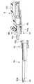
図1ないし図7は、本発明の1実施の形態に係り、図1は1実施の形態の超音波処置装置を示す全体構成図、図2は図1の装置本体の構成を示す回路ブロック図、図3は図1の超音波処置具の分解状態を示す側面図、図4は図1の超音波処置具全体の組立状態を示す側面図、図5はハンドルユニットの挿入部外套管付近の詳細構成を示す説明図、図6は操作ロッドと操作部本体との接続関係を示す説明図である。
【0017】
図1に示すように、本実施の形態の超音波処置装置1は、装置本体1Aに超音波処置具2及びフットスイッチ3がそれぞれ接続されている。
また、超音波処置具2は、細長いシース状の挿入部外套管4の先端部に処置部5、基端部に手元側の操作部6がそれぞれ配設されている。ここで、操作部6は、超音波振動を発生する図示しない超音波振動子が内蔵され、処置部5を操作する操作ハンドル8とが設けられている。
【0018】
更に、挿入部外套管4は、この内部に超音波振動子からの超音波振動を処置部5に伝達する振動伝達部材9が配設されている。この振動伝達部材9の先端部は、挿入部外套管4の先端から外部側に露出される。
また、装置本体1Aは、この前面に操作盤12が設けられている。この操作盤12は、電源スイッチ13と、操作表示パネル14と、超音波処置具接続部15とが設けられている。ここで、超音波処置具2の操作部6は、ハンドピースコード16の一端が連結されている。そして、このハンドピースコード16の他端部に配設されたハンドピースプラグ17は、装置本体1Aの超音波処置具接続部15に着脱可能に接続されるようになっている。
【0019】
また、装置本体1Aの操作表示パネル14は、超音波処置を行う際の通常運転時の超音波出力の大きさを設定する設定スイッチ18と、この設定スイッチ18で設定される超音波出力の大きさをデジタル表示する表示部19とが設けられている。この設定スイッチ18は、超音波出力の大きさを変更(増減)する出力増加スイッチ18aと、出力低減スイッチ18bとが設けられている。
更に、装置本体1Aは、図2に示すように超音波処置具2内の超音波振動子に電気エネルギを供給するための駆動回路20が内蔵されている。
【0020】
この駆動回路20は、超音波周波数の交流信号を発生する発振回路21と、超音波出力の大きさを指示する信号を生成するD/Aコンバータ22と、このD/Aコンバータ22からの信号に基づいて発振回路21の交流信号の大きさを制御するVCA回路23と、VCA回路23の出力を増幅して超音波処置具2内の超音波振動子を駆動する電力を生成するパワーアンプ24と、駆動回路20の出力ラインを入切するリレー25と、超音波処置装置1の動作を制御する制御回路26と、フットスイッチ3からの操作信号を制御回路26及びリレー25に伝達するインターフェース(I/F)回路27とが設けられている。
【0021】
また、制御回路26は、フットスイッチ3の操作による超音波処置の開始時に超音波処置具2内の超音波振動子からの超音波出力を設定スイッチ18による設定出力値よりも大きくし、超音波処置開始後、予め設定された所定の設定時間が経過した時点で、超音波振動子からの超音波出力が設定出力値になるように制御する運転状態切換え手段が内蔵されている。尚、駆動回路20のリレー25は、超音波処置具接続部15とパワーアンプ24との間に介設されている。
【0022】
超音波処置具2は、図3及び図4に示すように、3つのユニットに分解可能である。即ち、ハンドルユニット31と、プローブユニット32と、振動子ユニット33とから構成されている。これらの3つのユニット31〜33は、図4で示す状態に組み立てられる。
【0023】
振動子ユニット33は、ハンドルユニット31に着脱可能に連結されるハンドピース34が設けられている。このハンドピース34は、円筒状カバー34a内に超音波振動を発生するための超音波振動子(不図示)が内蔵されている。
この超音波振動子は、先端側に振幅拡大を行なうホーン(不図示)が連結され、このホーンの先端側がプローブユニット32の基端側に取り付けられる。
【0024】
また、円筒状カバー34aは、この先端部にハンドルユニット31の後述する操作部本体6aの振動子接続部6bに着脱可能に連結されるユニット連結部34bが設けられている。このユニット連結部34bの外周面は、リングの一部を切り離したC字型の形状をしている係合リング39(所謂Cリング)が装着されている。尚、係合リング39は、この断面形状が外周を円弧とする略半月状の断面形状に形成されている。
【0025】
また、円筒状カバー34aの後端部は、端部にハンドピースプラグ17を設けたハンドピースコード16が接続されている。
また、プローブユニット32は、振動子ユニット33における図示しないホーンの先端側に着脱可能に連結される細長い略棒状の振動伝達部材9が設けられている。
【0026】
この振動伝達部材9の基端部は、ホーンのプローブ取付部36aに連結される取付けねじ41aが形成されている。そして、この取付けねじ41aは、振動子ユニット13におけるプローブ取付部36aのねじ穴部にねじ込み固定されている。これにより、プローブユニット32と、振動子ユニット33とは、一体的に組み付けられている。
更に、振動伝達部材9は、基端側から伝達される超音波振動の定在波の節の位置(複数個所)にフランジ状の支持体41bが設けられている。この支持体41bは、弾性部材でリング状に形成されている。
【0027】
また、本実施の形態の振動伝達部材9は、基端部側から2つ目の節の前方に第2段階の振幅拡大を行なう基端側ホーン41cが配設されている。更に、この基端側ホーン41cの先端部側は、超音波振動の伝達を行う中間部41d、最終的な振幅拡大を行う先端側ホーン41e、処置部41f(超音波プローブ)が順次配設されている。ここで、振動伝達部材9の最先端部に配置された処置部41fは、例えば、略円柱形状に形成されている。
【0028】
また、ハンドルユニット31は、細長い挿入シース部31aと、この挿入シース部31aの先端部に配設された先端作用部31bと、挿入シース部31aの基端部に配設された操作部6とから構成される。ここで、ハンドルユニット31の操作部6は、略円筒状の操作部本体6aが設けられている。そして、この操作部本体6aの基端部は、振動子接続部6bが形成されている。
【0029】
また、操作部本体6aは、この外周面に固定ハンドル42と、操作手段を構成する回動可能な可動ハンドル43とが設けられ、固定ハンドル42及び可動ハンドル43によって操作ハンドル8(図1参照)が構成される。
また、操作部本体6aは、図示しない高周波電源装置が接続される高周波接続用の電極ピン44が設けられている。
【0030】
また、固定ハンドル42の上側部分は、円筒状の操作部本体6aと一体成形されている。更に、固定ハンドル42の操作端部は、親指以外の指の複数のものを選択的に差し込める指掛け孔42aが設けられ、可動ハンドル43の操作端部は、同じ手の親指を掛ける指掛け孔43aが設けられている。
【0031】
また、可動ハンドル43の上端部側は、二股状の連結部43bが形成されている。これらの二股状の連結部43bは、操作部本体6aの両側に配置されている。更に、各連結部43bの上端部は、ハンドル枢支軸45が内方向に向けて突設されている。これらのハンドル枢支軸45は、挿入部外套管4の軸線より上側位置の支点で操作部本体6aに連結されている。これにより、可動ハンドル43は、ハンドル枢支軸45によって回動可能に枢支されている。尚、ハンドル枢支軸45は、高周波絶縁用の絶縁キャップが取り付けられている。
【0032】
更に、可動ハンドル43の各連結部43bは、ハンドル枢支軸45の下側に作動軸47が設けられている。この作動軸47は、挿入部外套管4内を挿通する操作ロッド50(図5参照:操作力伝達部材)に進退力を伝達するためのものである。尚、本実施の形態では、操作ロッド50は、後述するように管状に形成されている。
【0033】
そして、操作ロッド50は、軸方向に進退する動作によって、処置部41fに対して後述のジョー51に開閉操作を行わせる。即ち、可動ハンドル43と作動軸47とは、操作手段を構成している。尚、作動軸47は、挿入部外套管4の略軸線上に配置されている。
【0034】
本実施の形態では、超音波処置具2は、ハンドルを握って可動ハンドル43を閉操作すると、作動軸47が前側に移動することで、操作ロッド50を前側に押し出し、処置部41fに対してジョー51が閉じるように構成されている。
【0035】
また、挿入シース部31aは、上述したように、挿入部外套管4が設けられ、この挿入部外套管4の基端部は、回転ノブ48とともに、操作部本体6aの先端部にこの操作部本体6aの中心線の軸回り方向に回転可能に取付けられている。ここで、挿入部外套管4は、図示しない金属管の外周面に絶縁チューブ49が装着されて形成されている。この絶縁チューブ49は、挿入部外套管4の外周面全体を基端部までの大部分被覆する状態に設けられる。
【0036】
また、ハンドルユニット31は、先端作用部31bに生体組織を把持するための片開き型のジョー51が回動自在に取り付けられている。このジョー51には、後述するように操作ロッド50を連結する。 ◎
ジョー51には、先端側に把持部材54が配置されている。具体的には、ジョー51は、把持部材54を挟み込むようにして一体的に連結して取り付けている。
【0037】
この把持部材54は、生体組織に当接する当接面の両端に略鋸歯状の歯部55が形成されている。尚、把持部材54は、例えばPTFE(テフロン:デュポン社商標名)等の低摩擦材料で形成されている。また、把持部材54は、ジョー51に対して揺動可能として、単体では、剛性に乏しいので、図示しない金属製の強度部材を取り付けて剛性を確保しても良い。
【0038】
挿入部外套管4は、この先端部にジョー51を保持するジョー保持部52が設けられている。このジョー保持部52は、略管状の保持部材本体52aの先端部が絶縁カバー53で被覆され、高周波電流に対する絶縁が行われている。更に、ジョー51には、生体組織(臓器)を把持する把持部材54が取り付けられている。
【0039】
また、挿入部外套管4には、プローブユニット32の振動伝達部材9が挿通されている。また、この挿入部外套管4は、振動伝達部材9を囲繞して、管状の操作ロッド50が進退自在に挿通されている。尚、操作ロッド50は、挿入部外套管4内に隙間を残して配置されている。
【0040】
次に、図5を用いてハンドルユニット31の挿入部外套管4付近の詳細構成を説明する。図5は、ハンドルユニット31の挿入部外套管4付近の詳細構成を示す説明図である。
【0041】
図5に示すようにハンドルユニット31は、ジョー51の取付け部が挿入部外套管4の保持部材本体52aの先端に形成されたスロット52bに挿入され、枢支軸60を介して保持部材本体52aに回動可能に取り付けられている。尚、図5では、絶縁カバー53が取り外されている状態を示している。保持部材本体52aの十分な強度を確保するため、スロット52bは、保持部材本体52aを上下に貫通することなく保持部材本体52aの上側でのみ開口している。即ち、スロット52bが形成された保持部材本体52aの部位の断面形状は、U字型を成している。
【0042】
また、ジョー51は、その基端部に操作ロッド50が連結されるための係合溝61が形成されている。操作ロッド50は、管状に形成されており、その先端側に先端連結部50aが延出している。この先端連結部50aは、ジョー51の係合溝61に係合する係合突起部62が形成されている。
【0043】
そして、操作ロッド50は、ジョー51の基端側に形成された軸方向のスロット(図示せず)内にその先端連結部50aが挿入され、その状態で先端連結部50aの係合突起部62を係合溝61に嵌めこむことでジョー51に連結されるようになっている。
【0044】
このことにより、操作ロッド50とジョー51とは、枢支軸60より上で連結される。従って、操作ロッド50が進退すると、ジョー51は、枢支軸60を中心に回動(開閉)する。
【0045】
尚、操作ロッド50とジョー51との連結は、図示しないが操作ロッド50に軸孔を形成し、挿入部外套管4の保持部材本体52aに係合孔を形成して、この係合孔から枢支ピンを挿通するように構成しても構わない。
【0046】
ジョー51の閉操作時は、プローブユニット32の処置部41fに対してジョー51の把持部材54を押し付けることにより、処置部41fと把持部材54との間で生体組織を把持するようになっている。このとき、把持部材54は、把持した生体組織に全面に亘って当接するようになっている。そして、把持された生体組織は、高速で振動する処置部41fとの摩擦熱によって凝固或いは切開等の超音波処置を施される。尚、ジョー51は、生体組織の剥離にも使用される。
【0047】
そして、超音波処置具2は、使用後、洗滌、滅菌消毒する必要がある。
本実施の形態では、洗滌し易いように操作ロッド50を露出するため、ジョー51を保持したまま挿入部外套管4を操作部6に対して着脱可能に構成している。
【0048】
即ち、挿入部外套管4は、操作部本体6aの先端側に着脱自在に接続可能な基端側接続部71を設けている。この基端側接続部71は、内周面に雌ねじ部71aを形成している。一方、操作部本体6aは、回転ノブ48の先端側に挿入部外套管4の基端側接続部71が接続される外套管接続部72を設けている。この外套管接続部72は、外周面に雄ねじ部72aを形成している。
【0049】
そして、超音波処置具2において、挿入部外套管4はその基端側接続部71を操作部本体6aの外套管接続部72に螺合することで回転自在に接続され、その回転方向の位置決めを上述したジョー51と操作ロッド50との連結により行うようになっている。
【0050】
このことにより、超音波処置具2は、使用後、洗滌する際に、ジョー51と操作ロッド50との連結を解除してジョー51を保持したまま挿入部外套管4を操作部本体6aから取り外すことができる。
【0051】
従って、超音波処置具2は、操作ロッド50を露出することができ、この操作ロッド50の洗滌が容易となる。また、超音波処置具2は、適宜、消耗品としてジョー51を含む挿入部外套管4の交換が可能となる。
【0052】
更に、本実施の形態では、超音波処置具2は、図6に示すように管状の操作ロッド50を操作部本体6aから取り外すことができるように構成している。
図6は、操作ロッド50と操作部本体6aとの接続関係を示す説明図である。
【0053】
図6に示すように超音波処置具2は、操作部本体6aに対して管状の操作ロッド50を着脱自在に構成している。
更に、具体的に説明すると、操作ロッド50は、操作部本体6aの先端側に着脱自在に接続可能な基端側接続部73を設けている。この基端側接続部73は、外周面に雄ねじ部73aを形成している。
【0054】
一方、操作部本体6aは、この内部に操作ロッド50の基端側接続部73が接続される操作ロッド接続部74を設けている。この操作ロッド接続部74は、スライダ75の先端側に設けられている。この操作ロッド接続部74は、先端側内周面に雌ねじ部74aを形成している。尚、スライダ75は、長手軸方向に進退して可動ハンドル43の操作力を操作ロッド50に伝達するためのものである。
そして、超音波処置具2は、操作ロッド50の基端側接続部73を操作部本体6aのスライダ75に螺合することで操作ロッド50を着脱自在に接続するようになっている。
【0055】
このことにより、超音波処置具2は、挿入部外套管4を操作部本体6aから取り外して操作ロッド50を露出させた後、この操作ロッド50を操作部本体6aから取り外すことができる。
従って、超音波処置具2は、操作ロッド50を取り外すことができ、この操作ロッド50の洗滌が更に容易となる。また、超音波処置具2は、適宜、消耗品としてジョー51、挿入部外套管4及び操作ロッド50の交換が可能となる。
【0056】
この結果、本実施の形態の超音波処置装置1は、ジョー51を保持したまま挿入部外套管4を操作部6に対して着脱可能に構成しているので、操作ロッド50を露出して洗滌し易い。また、本実施の形態の超音波処置装置1は、挿入部外套管4を消耗品として交換可能である。
【0057】
更に、本実施の形態の超音波処置装置1は、操作ロッド50を操作部本体6aに着脱可能に構成しているので、操作ロッド50の洗滌が更に容易となり、消耗品として交換可能である。
尚、本実施の形態では、操作ロッド50は、管状に形成したものを用いて構成しているが、操作ロッド50が剛性を確保できれば、棒状に形成したものを用いて構成しても構わない。
【0058】
また、本発明は、上述した実施の形態に限定されるものではなく、本発明の要旨を変えない範囲において、種々の変更、改変等が可能である。
【0059】
[付記]
(付記項1) 超音波振動子で発生した超音波振動を伝達し、生体組織を処置する超音波プローブと、
前記超音波プローブに対峙して回動自在に支持され、この超音波プローブとの間に生体組織を把持するジョーと、
前記ジョーを前記超音波プローブに対して開閉操作するための操作部と、
前記ジョーと前記操作部との間を連結して前記ジョーに前記操作部からの操作力を伝達する操作力伝達部材と、
前記操作力伝達部材を覆い、前記ジョーを先端側に設けた挿入部外套管と、
を具備し、
前記ジョーと前記操作力伝達部材とを着脱可能とし、前記操作部に対して前記挿入部外套管を着脱可能に構成したことを特徴とする超音波処置装置。
【0060】
(付記項2) 超音波振動子で発生した超音波振動を伝達し、生体組織を処置する超音波プローブと、
前記超音波プローブに対峙して回動自在に支持され、この超音波プローブとの間に生体組織を把持するジョーと、
前記ジョーを前記超音波プローブに対して開閉操作するための操作部と、
前記ジョーと前記操作部との間を連結して前記ジョーに前記操作部からの操作力を伝達する操作力伝達部材と、
前記操作力伝達部材を覆い、前記ジョーを先端側に設けた挿入部外套管と、
前記超音波振動子を制御駆動するための駆動回路と、
を具備し、
前記ジョーと前記操作力伝達部材とを着脱可能とし、前記操作部に対して前記挿入部外套管を着脱可能に構成したことを特徴とする超音波処置装置。
【0061】
(付記項3) 更に、前記操作部に対して前記操作力伝達部材を着脱可能に構成したことを特徴とする付記項1又は2に記載の超音波処置装置。
【0062】
【発明の効果】
以上説明したように本発明によれば、操作力伝達部材を容易に露出でき、操作力伝達部材を容易に洗滌可能な超音波処置装置を実現できる。
【図面の簡単な説明】
【図1】第1の実施の形態の超音波処置装置を示す全体構成図
【図2】図1の装置本体の構成を示す回路ブロック図
【図3】図1の超音波処置具の分解状態を示す側面図
【図4】図1の超音波処置具全体の組立状態を示す側面図
【図5】ハンドルユニットの挿入部外套管付近の詳細構成を示す説明図
【図6】操作ロッドと操作部本体との接続関係を示す説明図
【符号の説明】
1…超音波処置装置
1A…装置本体
2…超音波処置具
4…挿入部外套管
5…処置部
6…操作部
9…振動伝達部材
31…ハンドルユニット
32…プローブユニット
33…振動子ユニット
41f…処置部(超音波プローブ)
50…操作ロッド
50a…先端連結部
51…ジョー
52…ジョー保持部
52a…保持部本体
60…枢支軸
61…係合溝
62…係合突起部
71…基端側接続部
71a…雌ねじ部
72…外套管接続部
72a…雄ねじ部[0001]
BACKGROUND OF THE INVENTION
The present invention relates to an ultrasonic treatment apparatus that grasps a biological tissue and performs ultrasonic treatment such as incision, excision, or coagulation of the biological tissue.
[0002]
[Prior art]
Generally, an ultrasonic treatment apparatus performs ultrasonic treatment such as incision, excision, or coagulation on a living tissue.
In such an ultrasonic treatment apparatus, a proximal-side operation unit is connected to the proximal end portion of the insertion portion mantle tube, and an ultrasonic transducer that generates ultrasonic vibration is disposed in the operation unit, and the insertion portion An ultrasonic probe for treating living tissue is disposed at the distal end portion of the outer tube.
[0003]
In the ultrasonic treatment apparatus, a vibration transmitting member that transmits ultrasonic vibration from the ultrasonic transducer to the ultrasonic probe is inserted into the insertion portion mantle tube. The base end portion of the vibration transmitting member is connected to the ultrasonic transducer. Furthermore, the ultrasonic treatment apparatus is provided with a jaw that is rotatably supported against the ultrasonic probe.
[0004]
In the ultrasonic treatment apparatus, a movable handle for opening and closing the jaw with respect to the ultrasonic probe is disposed in the operation unit. Further, an operation force transmission member for transmitting an operation force from the movable handle to the jaw is inserted into the insertion portion outer tube so as to be movable back and forth in the axial direction.
[0005]
In the ultrasonic treatment apparatus, the operation force transmission member is advanced and retracted in the axial direction in accordance with the operation of the movable handle, and the jaw is closed with respect to the ultrasonic probe in conjunction with the advance and retreat operation of the operation force transmission member. Accordingly, the living tissue is grasped between the ultrasonic probe and the jaw.
[0006]
Subsequently, in this state, the ultrasonic treatment device transmits the ultrasonic vibration from the ultrasonic transducer to the ultrasonic probe via the vibration transmission member, thereby incising and excising the grasped biological tissue. Alternatively, ultrasonic treatment such as coagulation is performed.
[0007]
Such a conventional ultrasonic treatment apparatus includes, for example, a rod-like operating force transmission member on a channel tube of an insertion portion mantle tube as described in JP-A-2000-254135 and JP-A-2000-296133. Has been proposed which is inserted and arranged so as to be able to advance and retreat.
[0008]
These conventional ultrasonic treatment devices need to be cleaned and sterilized after use.
For this reason, the ultrasonic treatment apparatus described in JP 2000-254135 A includes an ultrasonic probe, a vibration transmission member, a jaw, a jaw holding member, and an operation force transmission member that are integrated. It is configured so that it can be removed from the outer sheath tube together with the ultrasonic transducer.
[0009]
On the other hand, the ultrasonic treatment apparatus described in JP 2000-296133 A is configured such that only the ultrasonic probe and the vibration transmitting member can be removed.
[0010]
[Patent Document 1]
Japanese Patent Laid-Open No. 2000-254135
[Patent Document 2]
Japanese Patent Laid-Open No. 2000-296133
[Problems to be solved by the invention]
However, the ultrasonic treatment apparatus described in Japanese Patent Laid-Open No. 2000-254135 has a complicated structure because the operating force transmission member is configured to be movable back and forth in the longitudinal axis direction.
For this reason, the ultrasonic treatment apparatus described in Japanese Patent Laid-Open No. 2000-254135 has the ultrasonic probe and the vibration transmission member as the ultrasonic vibrator when the ultrasonic probe and the vibration transmission member are attached to the ultrasonic vibrator. Since the operating force transmission member is twisted for screwing, a special jig is used. For this reason, the ultrasonic treatment apparatus described in Japanese Patent Laid-Open No. 2000-254135 is complicated to assemble and costs high.
[0013]
On the other hand, in the ultrasonic treatment apparatus described in JP 2000-296133 A, the operating force transmission member cannot be disassembled only by removing the ultrasonic probe and the vibration transmission member.
For this reason, in the ultrasonic treatment apparatus described in the above-mentioned Japanese Patent Application Laid-Open No. 2000-296133, the operation force transmission member is washed with running water.
[0014]
The present invention has been made in view of these circumstances, and an object of the present invention is to provide an ultrasonic treatment apparatus thatcaneasily exposean operating force transmission member and can easily wash theoperating force transmission member .
[0015]
[Means for Solving the Problems]
The ultrasonic treatment apparatus of the present invention has adistal end portion and a proximalend portion, and transmitsan ultrasonic vibration generated by an ultrasonic transducer from theproximal end portion to the distal end portion;supportedso as to be rotatablewith respect to the tip portion of the ultrasonic probe,wherein the jaws for gripping the living tissue between the ultrasonic probe, for opening and closing the jaw relative to the ultrasonic probe An operating portion isdetachable from the jaw, and after the mounting, the jaw is made rotatable, and the jaw and the operating portion are connected to each other to operate the jaw from the operating portion. An operating force transmission member for transmitting the operating force,a first attaching / detaching portion that covers the operating force transmitting member androtatably supports the jaw on the distalend side, and is provided on the proximal end side with respect to the operating portion. A detachable insertion tube through theAnd characterizedin thatit.
[0016]
DETAILED DESCRIPTION OF THE INVENTION
Hereinafter, an embodiment of the present invention will be described with reference to the drawings.
1 to 7 relate to one embodiment of the present invention, FIG. 1 is an overall configuration diagram showing an ultrasonic treatment apparatus of the embodiment, and FIG. 2 is a circuit block diagram showing a configuration of the apparatus main body of FIG. 3 is a side view showing the disassembled state of the ultrasonic treatment device of FIG. 1, FIG. 4 is a side view showing the assembled state of the entire ultrasonic treatment device of FIG. 1, and FIG. FIG. 6 is an explanatory view showing a detailed configuration, and FIG. 6 is an explanatory view showing a connection relationship between the operating rod and the operating portion main body.
[0017]
As shown in FIG. 1, in the
In the
[0018]
Further, the insertion portion outer tube 4 is provided with a
In addition, the
[0019]
The
Furthermore, the apparatus main body 1A incorporates a
[0020]
The
[0021]
In addition, the
[0022]
As shown in FIGS. 3 and 4, the
[0023]
The
In this ultrasonic transducer, a horn (not shown) for expanding the amplitude is connected to the distal end side, and the distal end side of the horn is attached to the proximal end side of the
[0024]
Further, the
[0025]
The rear end portion of the
In addition, the
[0026]
A mounting screw 41a connected to the probe mounting portion 36a of the horn is formed at the base end portion of the
Further, the
[0027]
Further, in the
[0028]
The
[0029]
In addition, the operation unit
Further, the
[0030]
The upper portion of the fixed
[0031]
Further, a bifurcated connecting
[0032]
Further, each connecting
[0033]
And the
[0034]
In the present embodiment, when the
[0035]
Further, as described above, the
[0036]
In the
A gripping
[0037]
The gripping
[0038]
The insertion portion outer tube 4 is provided with a
[0039]
Further, the
[0040]
Next, a detailed configuration of the vicinity of the insertion portion outer tube 4 of the
[0041]
As shown in FIG. 5, in the
[0042]
Further, the
[0043]
The operating
[0044]
Thus, the
[0045]
Although not shown, the
[0046]
During the closing operation of the
[0047]
And the
In the present embodiment, since the
[0048]
That is, the insertion portion outer tube 4 is provided with a proximal end
[0049]
In the
[0050]
Accordingly, when the
[0051]
Therefore, the
[0052]
Further, in the present embodiment, the
FIG. 6 is an explanatory diagram showing a connection relationship between the
[0053]
As shown in FIG. 6, the
More specifically, the
[0054]
On the other hand, the operation portion
And the
[0055]
Accordingly, the
Therefore, the
[0056]
As a result, the
[0057]
Furthermore, in the
In the present embodiment, the
[0058]
The present invention is not limited to the above-described embodiments, and various changes and modifications can be made without departing from the scope of the present invention.
[0059]
[Appendix]
(Additional Item 1) An ultrasonic probe that transmits ultrasonic vibration generated by an ultrasonic transducer and treats living tissue;
A jaw that is rotatably supported against the ultrasonic probe, and grips a living tissue between the ultrasonic probe;
An operation unit for opening and closing the jaw with respect to the ultrasonic probe;
An operation force transmitting member that connects the jaw and the operation unit and transmits an operation force from the operation unit to the jaw;
An insertion portion mantle tube covering the operating force transmission member and having the jaw provided on the distal end side;
Comprising
An ultrasonic treatment apparatus, wherein the jaw and the operation force transmission member are detachable, and the insertion portion outer tube is detachable from the operation portion.
[0060]
(Additional Item 2) An ultrasonic probe that transmits ultrasonic vibration generated by an ultrasonic transducer and treats living tissue;
A jaw that is rotatably supported against the ultrasonic probe, and grips a living tissue between the ultrasonic probe;
An operation unit for opening and closing the jaw with respect to the ultrasonic probe;
An operation force transmitting member that connects the jaw and the operation unit and transmits an operation force from the operation unit to the jaw;
An insertion portion mantle tube covering the operating force transmission member and having the jaw provided on the distal end side;
A drive circuit for controlling and driving the ultrasonic transducer;
Comprising
An ultrasonic treatment apparatus, wherein the jaw and the operation force transmission member are detachable, and the insertion portion outer tube is detachable from the operation portion.
[0061]
(Additional Item 3) The ultrasonic treatment apparatus according to
[0062]
【The invention's effect】
As described above, according to the present invention, it is possible to realize an ultrasonic treatment apparatus that caneasily exposethe operation force transmission member and easily clean theoperation force transmission member .
[Brief description of the drawings]
FIG. 1 is an overall configuration diagram showing an ultrasonic treatment apparatus according to a first embodiment. FIG. 2 is a circuit block diagram showing a configuration of the apparatus main body of FIG. 1. FIG. 3 is an exploded state of the ultrasonic treatment instrument of FIG. FIG. 4 is a side view showing an assembled state of the entire ultrasonic treatment apparatus of FIG. 1. FIG. 5 is an explanatory view showing a detailed configuration in the vicinity of the outer tube of the handle unit insertion portion. Explanatory diagram showing the connection relationship with the main unit [Explanation of symbols]
DESCRIPTION OF
50 ...
Claims (3)
Translated fromJapanese前記超音波プローブの前記先端部に対して回動自在となるよう支持された、前記超音波プローブとの間に生体組織を把持するジョーと、
前記ジョーを前記超音波プローブに対して開閉操作するための操作部と、
前記ジョーに対して着脱可能であって、装着後、前記ジョーを回動自在とするとともに前記ジョーと前記操作部との間を連結して前記ジョーに前記操作部からの操作力を伝達する操作力伝達部材と、
前記操作力伝達部材を覆い、前記ジョーを先端側に回動自在に支持するとともに、前記操作部に対して、基端側に設けられた第1の着脱部を介して着脱自在な挿入部外套管と、
を具備していることを特徴とする超音波処置装置。An ultrasonic probe havingadistal end portion and a proximal end portion and transmitting ultrasonic vibration generated by an ultrasonic transducer from theproximal end portion to the distal end portion ;
A jaw for gripping a living tissue betweenthesupportedso as to be rotatablewith respect to the distal end portion,the ultrasonic probe of the ultrasonic probe,
An operation unit for opening and closing the jaw with respect to the ultrasonic probe;
An operation that is detachable with respect to the jaw and that allows the jaw to turn freely after being mounted and that connects the jaw and the operation portion to transmit the operation force from the operation portion to the jaw. A force transmission member;
The operating force transmission member is covered, the jaw isrotatably supported on the distalend side, and is detachably attached to the operating portion via a first attaching / detaching portion provided on the proximal end side. Tube,
An ultrasonic treatment apparatus comprising:
前記第1の着脱部は、前記外套管接続部に対して着脱自在であるとともに、前記操作力伝達部材の基端側に設けられた第2の着脱部は、前記伝達部材接続部に着脱自在であることを特徴とする請求項1に記載の超音波処置装置。The first attaching / detaching portion is attachable / detachable to / from the outer tube connecting portion, and a second attaching / detaching portion provided on the proximal end side of the operation force transmitting member is attachable / detachable to / from the transmitting member connecting portion. The ultrasonic treatment apparatus according to claim 1, wherein:
Priority Applications (1)
| Application Number | Priority Date | Filing Date | Title |
|---|---|---|---|
| JP2003078851AJP4315716B2 (en) | 2003-03-20 | 2003-03-20 | Ultrasonic treatment device |
Applications Claiming Priority (1)
| Application Number | Priority Date | Filing Date | Title |
|---|---|---|---|
| JP2003078851AJP4315716B2 (en) | 2003-03-20 | 2003-03-20 | Ultrasonic treatment device |
Publications (2)
| Publication Number | Publication Date |
|---|---|
| JP2004283361A JP2004283361A (en) | 2004-10-14 |
| JP4315716B2true JP4315716B2 (en) | 2009-08-19 |
Family
ID=33293217
Family Applications (1)
| Application Number | Title | Priority Date | Filing Date |
|---|---|---|---|
| JP2003078851AExpired - Fee RelatedJP4315716B2 (en) | 2003-03-20 | 2003-03-20 | Ultrasonic treatment device |
Country Status (1)
| Country | Link |
|---|---|
| JP (1) | JP4315716B2 (en) |
Families Citing this family (3)
| Publication number | Priority date | Publication date | Assignee | Title |
|---|---|---|---|---|
| JP4282523B2 (en) | 2004-03-30 | 2009-06-24 | オリンパス株式会社 | Ultrasonic treatment device |
| KR101662448B1 (en)* | 2015-05-21 | 2016-10-04 | 한국생산기술연구원 | Endoscopic instrument with replaceable head portion |
| CN107280735B (en)* | 2017-07-21 | 2020-08-04 | 上海逸思医疗科技有限公司 | Repeatedly-usable ultrasonic surgical instrument |
- 2003
- 2003-03-20JPJP2003078851Apatent/JP4315716B2/ennot_activeExpired - Fee Related
Also Published As
| Publication number | Publication date |
|---|---|
| JP2004283361A (en) | 2004-10-14 |
Similar Documents
| Publication | Publication Date | Title |
|---|---|---|
| US7563269B2 (en) | Ultrasonic treatment device | |
| JP3600070B2 (en) | Ultrasonic treatment tool | |
| JP2004209043A (en) | Ultrasonic treatment apparatus | |
| JP4402629B2 (en) | Ultrasonic coagulation and incision device | |
| CN101396300B (en) | Surgical operating apparatus | |
| JP4879966B2 (en) | Coagulation and incision device | |
| JP2009261912A (en) | Surgical operating apparatus | |
| JP3831233B2 (en) | Surgical tools | |
| JP4315716B2 (en) | Ultrasonic treatment device | |
| JP2001353165A (en) | Operation instrument | |
| JP2000210301A (en) | Surgical appliance | |
| JP4248884B2 (en) | Ultrasonic treatment device | |
| JP4331504B2 (en) | Ultrasonic treatment device | |
| JP3270415B2 (en) | Ultrasonic coagulation incision device | |
| JP4328122B2 (en) | Ultrasonic treatment device | |
| JP2001017385A (en) | Surgical instrument | |
| JP4323204B2 (en) | Ultrasonic treatment device | |
| JP2004337187A (en) | Ultrasonic treating apparatus | |
| JP2004033565A (en) | Ultrasonic treatment instrument | |
| JP2004313540A (en) | Ultrasonic treatment apparatus | |
| JP4253517B2 (en) | Ultrasonic treatment device | |
| JP2004305589A (en) | Ultrasonic treating apparatus | |
| JP4253513B2 (en) | Ultrasonic treatment device | |
| JP2004141341A (en) | Ultrasonic surgical device | |
| JP4276873B2 (en) | Ultrasonic treatment device |
Legal Events
| Date | Code | Title | Description |
|---|---|---|---|
| A621 | Written request for application examination | Free format text:JAPANESE INTERMEDIATE CODE: A621 Effective date:20060116 | |
| A131 | Notification of reasons for refusal | Free format text:JAPANESE INTERMEDIATE CODE: A131 Effective date:20090210 | |
| A521 | Written amendment | Free format text:JAPANESE INTERMEDIATE CODE: A523 Effective date:20090403 | |
| TRDD | Decision of grant or rejection written | ||
| A01 | Written decision to grant a patent or to grant a registration (utility model) | Free format text:JAPANESE INTERMEDIATE CODE: A01 Effective date:20090428 | |
| A01 | Written decision to grant a patent or to grant a registration (utility model) | Free format text:JAPANESE INTERMEDIATE CODE: A01 | |
| A61 | First payment of annual fees (during grant procedure) | Free format text:JAPANESE INTERMEDIATE CODE: A61 Effective date:20090519 | |
| R151 | Written notification of patent or utility model registration | Ref document number:4315716 Country of ref document:JP Free format text:JAPANESE INTERMEDIATE CODE: R151 | |
| FPAY | Renewal fee payment (event date is renewal date of database) | Free format text:PAYMENT UNTIL: 20120529 Year of fee payment:3 | |
| FPAY | Renewal fee payment (event date is renewal date of database) | Free format text:PAYMENT UNTIL: 20130529 Year of fee payment:4 | |
| FPAY | Renewal fee payment (event date is renewal date of database) | Free format text:PAYMENT UNTIL: 20140529 Year of fee payment:5 | |
| S531 | Written request for registration of change of domicile | Free format text:JAPANESE INTERMEDIATE CODE: R313531 | |
| R350 | Written notification of registration of transfer | Free format text:JAPANESE INTERMEDIATE CODE: R350 | |
| R250 | Receipt of annual fees | Free format text:JAPANESE INTERMEDIATE CODE: R250 | |
| R250 | Receipt of annual fees | Free format text:JAPANESE INTERMEDIATE CODE: R250 | |
| LAPS | Cancellation because of no payment of annual fees |