JP4315440B2 - Objective lens for optical recording medium and optical pickup device using the same - Google Patents
Objective lens for optical recording medium and optical pickup device using the sameDownload PDFInfo
- Publication number
- JP4315440B2 JP4315440B2JP2004105252AJP2004105252AJP4315440B2JP 4315440 B2JP4315440 B2JP 4315440B2JP 2004105252 AJP2004105252 AJP 2004105252AJP 2004105252 AJP2004105252 AJP 2004105252AJP 4315440 B2JP4315440 B2JP 4315440B2
- Authority
- JP
- Japan
- Prior art keywords
- light
- optical recording
- recording medium
- wavelength
- objective lens
- Prior art date
- Legal status (The legal status is an assumption and is not a legal conclusion. Google has not performed a legal analysis and makes no representation as to the accuracy of the status listed.)
- Expired - Fee Related
Links
- 230000003287optical effectEffects0.000titleclaimsdescription263
- 239000000758substrateSubstances0.000claimsdescription48
- 239000000463materialSubstances0.000claimsdescription42
- 230000014509gene expressionEffects0.000claimsdescription29
- 230000009471actionEffects0.000description12
- 239000004065semiconductorSubstances0.000description12
- 230000004075alterationEffects0.000description10
- 230000000694effectsEffects0.000description9
- 230000004907fluxEffects0.000description7
- 238000000034methodMethods0.000description4
- 239000011241protective layerSubstances0.000description4
- 230000008859changeEffects0.000description3
- 238000012937correctionMethods0.000description3
- 238000011161developmentMethods0.000description3
- 238000010586diagramMethods0.000description3
- 239000011347resinSubstances0.000description3
- 229920005989resinPolymers0.000description3
- 238000013461designMethods0.000description2
- 238000012986modificationMethods0.000description2
- 230000004048modificationEffects0.000description2
- 239000004417polycarbonateSubstances0.000description2
- 238000012827research and developmentMethods0.000description2
- 230000004044responseEffects0.000description2
- 230000002411adverseEffects0.000description1
- 238000013459approachMethods0.000description1
- 238000005452bendingMethods0.000description1
- 239000011248coating agentSubstances0.000description1
- 238000000576coating methodMethods0.000description1
- 239000002131composite materialSubstances0.000description1
- 238000002788crimpingMethods0.000description1
- 238000003384imaging methodMethods0.000description1
- 238000005304joiningMethods0.000description1
- 238000004519manufacturing processMethods0.000description1
- 239000004033plasticSubstances0.000description1
- 229920000515polycarbonatePolymers0.000description1
- 238000003672processing methodMethods0.000description1
- 230000002250progressing effectEffects0.000description1
- 230000035945sensitivityEffects0.000description1
- 238000004904shorteningMethods0.000description1
- 239000002356single layerSubstances0.000description1
Images

Classifications
- G—PHYSICS
- G11—INFORMATION STORAGE
- G11B—INFORMATION STORAGE BASED ON RELATIVE MOVEMENT BETWEEN RECORD CARRIER AND TRANSDUCER
- G11B7/00—Recording or reproducing by optical means, e.g. recording using a thermal beam of optical radiation by modifying optical properties or the physical structure, reproducing using an optical beam at lower power by sensing optical properties; Record carriers therefor
- G11B7/12—Heads, e.g. forming of the optical beam spot or modulation of the optical beam
- G11B7/135—Means for guiding the beam from the source to the record carrier or from the record carrier to the detector
- G11B7/1353—Diffractive elements, e.g. holograms or gratings
- G—PHYSICS
- G11—INFORMATION STORAGE
- G11B—INFORMATION STORAGE BASED ON RELATIVE MOVEMENT BETWEEN RECORD CARRIER AND TRANSDUCER
- G11B7/00—Recording or reproducing by optical means, e.g. recording using a thermal beam of optical radiation by modifying optical properties or the physical structure, reproducing using an optical beam at lower power by sensing optical properties; Record carriers therefor
- G11B7/12—Heads, e.g. forming of the optical beam spot or modulation of the optical beam
- G11B7/135—Means for guiding the beam from the source to the record carrier or from the record carrier to the detector
- G11B7/1372—Lenses
- G11B7/1374—Objective lenses
- G—PHYSICS
- G11—INFORMATION STORAGE
- G11B—INFORMATION STORAGE BASED ON RELATIVE MOVEMENT BETWEEN RECORD CARRIER AND TRANSDUCER
- G11B7/00—Recording or reproducing by optical means, e.g. recording using a thermal beam of optical radiation by modifying optical properties or the physical structure, reproducing using an optical beam at lower power by sensing optical properties; Record carriers therefor
- G11B7/12—Heads, e.g. forming of the optical beam spot or modulation of the optical beam
- G11B7/135—Means for guiding the beam from the source to the record carrier or from the record carrier to the detector
- G11B7/1372—Lenses
- G11B7/1376—Collimator lenses
- G—PHYSICS
- G11—INFORMATION STORAGE
- G11B—INFORMATION STORAGE BASED ON RELATIVE MOVEMENT BETWEEN RECORD CARRIER AND TRANSDUCER
- G11B7/00—Recording or reproducing by optical means, e.g. recording using a thermal beam of optical radiation by modifying optical properties or the physical structure, reproducing using an optical beam at lower power by sensing optical properties; Record carriers therefor
- G11B7/12—Heads, e.g. forming of the optical beam spot or modulation of the optical beam
- G11B7/135—Means for guiding the beam from the source to the record carrier or from the record carrier to the detector
- G11B7/1392—Means for controlling the beam wavefront, e.g. for correction of aberration
- G11B7/13922—Means for controlling the beam wavefront, e.g. for correction of aberration passive
- G—PHYSICS
- G11—INFORMATION STORAGE
- G11B—INFORMATION STORAGE BASED ON RELATIVE MOVEMENT BETWEEN RECORD CARRIER AND TRANSDUCER
- G11B7/00—Recording or reproducing by optical means, e.g. recording using a thermal beam of optical radiation by modifying optical properties or the physical structure, reproducing using an optical beam at lower power by sensing optical properties; Record carriers therefor
- G11B2007/0003—Recording, reproducing or erasing systems characterised by the structure or type of the carrier
- G11B2007/0006—Recording, reproducing or erasing systems characterised by the structure or type of the carrier adapted for scanning different types of carrier, e.g. CD & DVD
- G—PHYSICS
- G11—INFORMATION STORAGE
- G11B—INFORMATION STORAGE BASED ON RELATIVE MOVEMENT BETWEEN RECORD CARRIER AND TRANSDUCER
- G11B7/00—Recording or reproducing by optical means, e.g. recording using a thermal beam of optical radiation by modifying optical properties or the physical structure, reproducing using an optical beam at lower power by sensing optical properties; Record carriers therefor
- G11B7/12—Heads, e.g. forming of the optical beam spot or modulation of the optical beam
- G11B7/135—Means for guiding the beam from the source to the record carrier or from the record carrier to the detector
- G11B7/1372—Lenses
- G11B2007/13727—Compound lenses, i.e. two or more lenses co-operating to perform a function, e.g. compound objective lens including a solid immersion lens, positive and negative lenses either bonded together or with adjustable spacing
Landscapes
- Physics & Mathematics (AREA)
- Optics & Photonics (AREA)
- Lenses (AREA)
- Optical Head (AREA)
- Diffracting Gratings Or Hologram Optical Elements (AREA)
Description
Translated fromJapanese本発明は、情報の記録または再生がなされる際に、使用光学系の開口数、使用光の波長および基板厚等の規格が異なる3つの光記録媒体に対して、各使用光を対応する光記録媒体上に効率良く収束させることができる光記録媒体用対物レンズおよびこれを用いた光ピックアップ装置に関するものであり、詳しくは、レンズ面に形成された回折光学面からの回折光を利用して、上記3つの光記録媒体のそれぞれに各使用光を良好に収束させる光記録媒体用対物レンズおよびこれを用いた光ピックアップ装置に関するものである。 In the present invention, when information is recorded or reproduced, light corresponding to each used light is applied to three optical recording media having different specifications such as the numerical aperture of the used optical system, the wavelength of the used light, and the substrate thickness. The present invention relates to an objective lens for an optical recording medium that can be efficiently converged on a recording medium and an optical pickup device using the same, and more specifically, using diffracted light from a diffractive optical surface formed on the lens surface. The present invention relates to an objective lens for an optical recording medium that favorably converges each used light on each of the three optical recording media, and an optical pickup device using the objective lens.
近年における種々の光記録媒体の開発に応じて、2種の光記録媒体の記録・再生に共用し得る光ピックアップ装置が知られている。例えば、DVD(ディジタル・バーサタイル・ディスク)とCD(コンパクトディスク。−ROM、−R、−RWを含む。)を1つの光ピックアップ装置を用いて記録・再生する装置が実用化されている。 In accordance with recent development of various optical recording media, an optical pickup device that can be shared for recording and reproduction of two types of optical recording media is known. For example, an apparatus for recording / reproducing a DVD (digital versatile disk) and a CD (compact disk including -ROM, -R, -RW) using one optical pickup device has been put into practical use.
このような2つの光記録媒体においては、DVDについては、記録密度の向上を図るため、例えば657nm程度の可視光を使用することとなっているのに対し、CDについては、可視光領域の光に対して感度を有さない記録媒体も存在するため、790nm程度の近赤外光を使用する必要がある。したがって、これら両者に対して共用し得る光ピックアップ装置では、2つの異なる波長の光を照射光として用いる、いわゆる2波長ビーム方式によることとなる。また、上述した例示における2つの光記録媒体においては、各光記録媒体の特性の違いからそれぞれ開口数を異ならせる必要があり、例えばDVDの規格では開口数を0.6とし、CDの規格では開口数を0.45〜0.52程度としている。さらに、これらの記録媒体においては、基板の厚み(PC(ポリカーボネート)からなる保護層を含む幾何学的厚みを示す。以下も同様である。)が互いに異なる規格とされており、例えばDVDでは0.6mmであるのに対し、CDでは1.2mmとされている。 In such two optical recording media, in order to improve the recording density for DVD, for example, visible light of about 657 nm is used, whereas for CD, light in the visible light region is used. However, there is a recording medium that has no sensitivity to the light, so it is necessary to use near infrared light of about 790 nm. Therefore, in an optical pickup device that can be used for both of them, a so-called two-wavelength beam method is used in which light of two different wavelengths is used as irradiation light. Further, in the two optical recording media in the above-described examples, it is necessary to make the numerical apertures different from each other due to the difference in characteristics of each optical recording medium. For example, the numerical aperture is set to 0.6 in the DVD standard, and the numerical aperture is set in the CD standard. Is about 0.45 to 0.52. Further, in these recording media, the thicknesses of the substrates (the geometrical thickness including the protective layer made of PC (polycarbonate) is shown) are different from each other. It is 1.2 mm for CD while it is mm.
そして、上述したように、光記録媒体の基板厚が光記録媒体の種類に応じて互いに異なるような規格とされていることから、その保護層の厚さの違いに応じ発生する球面収差の量が異なってくる。そのため、これらいずれの光記録媒体についても確実にフォーカシングをなすべく、記録・再生を行うための各波長の光のいずれについても球面収差量を最適化する必要があることから、互いに異なる収束作用を有するようなレンズ構成とする工夫を要する。 As described above, since the substrate thicknesses of the optical recording medium are different from each other depending on the type of the optical recording medium, the amount of spherical aberration generated according to the difference in the thickness of the protective layer Will be different. Therefore, in order to ensure focusing on any of these optical recording media, it is necessary to optimize the amount of spherical aberration for each of the wavelengths of light for recording / reproducing, so that different convergence effects can be obtained. It is necessary to devise a lens configuration that includes the lens.
特に、装置のコンパクト化等の要請に応じて、光学系の配置選択の自由度等を大きくすることが必要とされており、このためには、いずれの光記録媒体に対しても光源からの光を対物レンズに平行光束に近い状態で入射させ得る構成とすることが肝要であると考えられている。 In particular, it is necessary to increase the degree of freedom in selecting the arrangement of the optical system in response to a request for downsizing of the apparatus, and for this purpose, any optical recording medium is not affected by the light source. It is considered important to have a configuration in which light can be incident on the objective lens in a state close to a parallel light beam.
例えば、本願出願人が既に開示している下記特許文献1には、レンズ面に所定の回折光学面を形成することで、記録または再生を行う2種の光記録媒体についての光束のいずれについても略平行光として対物レンズに入射させ、かつこの2種の光記録媒体のいずれについても良好な収束作用を発揮し得るようにした光記録媒体用対物レンズが示されており、この特許文献1に記載のものによれば、光学系の配置選択の自由度等を大幅に増大させることができる。 For example, in the following Patent Document 1 already disclosed by the applicant of the present application, both of the light fluxes of two types of optical recording media on which recording or reproduction is performed by forming a predetermined diffractive optical surface on the lens surface. An objective lens for an optical recording medium is shown that is incident on an objective lens as substantially parallel light and can exhibit a good convergence effect for both of these two types of optical recording media. According to the description, the degree of freedom in selecting the arrangement of the optical system can be greatly increased.
ところで、日常取り扱われるデータ容量の急激な増大に応じて、光記録媒体の記録容量の増大化に対する要請は、さらに強いものとなってきている。光記録媒体の記録容量を増大させるためには、使用する光源光の短波長化と対物レンズの開口数(NA)を大きくすることが有効であることは知られているところであるが、短波長化に関しては、GaN基板をベースにした短波長の半導体レーザ(例えば、波長405nmのレーザ光を射出する)の開発が進展をみせており略実用化状態とされている。この短波長の半導体レーザの実用化に伴い、この短波長の光を照射光として使用する片面1層の容量が20GB程度のAOD(アドバンスド・オプティカル・ディスク:HD−DVD)に関する研究、開発も同様に進められている。このAODの規格においては、開口数および基板の厚みが上述したDVDに近いものの若干異なった値とされており、開口数(NA)は0.65、基板の厚みは0.6mmとされている。 By the way, in response to a rapid increase in the data capacity handled daily, there is an increasing demand for an increase in the recording capacity of the optical recording medium. In order to increase the recording capacity of an optical recording medium, it is known that shortening the wavelength of the light source used and increasing the numerical aperture (NA) of the objective lens are effective. Regarding the development of semiconductor lasers, the development of short-wavelength semiconductor lasers based on GaN substrates (for example, emitting laser light having a wavelength of 405 nm) has been progressing and is in a practical state of practical use. Along with the practical use of this short-wavelength semiconductor laser, research and development on AOD (Advanced Optical Disc: HD-DVD) with a single-layer capacity of about 20 GB using this short-wavelength light as irradiation light is the same. It is advanced to. In this AOD standard, the numerical aperture and the substrate thickness are slightly different from those of the DVD described above, but the numerical aperture (NA) is 0.65 and the substrate thickness is 0.6 mm.
なお、AODと同様に短波長の光を照射光として使用するブルーレイディスクの研究、開発も進められており、その規格においては、開口数および基板の厚みが上述したDVDおよびCDとは全く異なった値(開口数(NA)は0.85、基板の厚みは0.1mm)とされている(以下、AODとブルーレイディスクを総称してAOD等と称することがある)。 In addition, research and development of a Blu-ray disc that uses short-wavelength light as irradiation light in the same way as AOD is underway, and in that standard, the numerical aperture and substrate thickness are completely different from those of DVD and CD described above. (Numerical aperture (NA) is 0.85, substrate thickness is 0.1 mm) (hereinafter, AOD and Blu-ray Disc may be collectively referred to as AOD or the like).
そこで、このAOD等と、上述したDVDおよびCDの3つの光記録媒体に対して共用し得る光ピックアップ装置の開発が望まれており、この装置に搭載される光記録媒体用対物レンズとしても、既に提案がなされている(例えば、下記特許文献2)。 Therefore, it is desired to develop an optical pickup device that can be used for the AOD and the above-described three optical recording media of DVD and CD. As an objective lens for an optical recording medium mounted on this device, Proposals have already been made (for example,
この公報記載のものは、互いに異なる波長の光に対する対物レンズの倍率変化を用いることによって残留する球面収差を低減するとともに、波長選択フィルタを用いることによって球面収差をさらに低減するようにしたもので、これにより複数種の光記録媒体の記録または再生を行なうことを可能としている。 In this publication, the remaining spherical aberration is reduced by using the magnification change of the objective lens with respect to light of different wavelengths, and the spherical aberration is further reduced by using a wavelength selection filter. As a result, it is possible to record or reproduce a plurality of types of optical recording media.
しかしながら、これら使用光波長が互いに異なる3種の光記録媒体のいずれに対しても光源からの光を対物レンズに平行光束に近い状態で入射させるという前述した条件が要求される場合には、上記特許文献1および2記載の技術によって対応することは困難である。 However, in the case where the above-described condition that the light from the light source is incident on the objective lens in a state close to a parallel light flux is required for any of these three types of optical recording media having different use light wavelengths, It is difficult to cope with the techniques described in
すなわち、上述した特許文献1および2の対物レンズにおいては1種または2種の光記録媒体について、両者の使用光を対物レンズに平行光束に近い状態で入射させた状態でこれら両者の記録または再生を良好に行なうように構成しているが、これが3種の光記録媒体についてということになれば、同様の作用効果を得ることは実際上困難である。 That is, in the above-described objective lenses of
したがって、上記条件が課された3種の光記録媒体用の対物レンズの実現は、対物レンズ全体の各波長に対する作用、すなわちレンズとしての各波長に対する屈折面の作用、また、レンズ面に回折光学面を設けた場合には、回折光学面での各波長に対する屈折および回折作用をいかにして良好に制御し得るか、という点にかかっていると考えられる。 Therefore, the realization of the objective lens for the three types of optical recording media imposed by the above conditions is effective for each wavelength of the entire objective lens, that is, the action of the refracting surface for each wavelength as the lens, and the diffractive optics on the lens surface. When the surface is provided, it is considered that it depends on how well the refraction and diffraction action for each wavelength on the diffractive optical surface can be controlled.
特に、回折光学面の各波長に対する屈折および回折作用を高精度に制御する手法が案出できれば、例えば、3種の光記録媒体のうち2種の光記録媒体に対してのみ上記条件が課されるような場合においても、より光学性能の優れた光記録媒体用対物レンズが容易に設計可能となり、その実用上の効果は極めて大きいものがあると考えられる。 In particular, if a method for controlling the refraction and diffraction action for each wavelength of the diffractive optical surface with high accuracy can be devised, for example, the above conditions are imposed only on two types of optical recording media among three types of optical recording media. Even in such a case, it is possible to easily design an objective lens for an optical recording medium with more excellent optical performance, and the practical effect is considered to be extremely large.
本発明は、かかる事情に鑑みなされたもので、情報の記録または再生がなされる際に、使用光学系の開口数、使用光の波長および基板厚等の規格が異なる3つの光記録媒体に対して、レンズ面に回折光学面を設けることで各使用光を対応する光記録媒体上に効率良く収束させることができる光記録媒体用対物レンズにおいて、光学系の配置選択の自由度を格段に高め得る光記録媒体用対物レンズおよびこれを用いた光ピックアップ装置を提供することを目的とするものである。 The present invention has been made in view of such circumstances. When information is recorded or reproduced, three optical recording media having different specifications such as the numerical aperture of the optical system used, the wavelength of the used light, and the substrate thickness are used. In addition, in the objective lens for an optical recording medium that can efficiently converge each used light on the corresponding optical recording medium by providing a diffractive optical surface on the lens surface, the degree of freedom in selecting the arrangement of the optical system is greatly increased. It is an object of the present invention to provide an objective lens for an optical recording medium to be obtained and an optical pickup device using the same.
上記課題を解決するため、本発明による光記録媒体用対物レンズは、
情報の記録または再生がなされる際に、対応する開口数、使用光波長および基板厚が下記3つの条件式(1)〜(3)を満足するように設定された第1、第2および第3の光記録媒体のそれぞれに対して、使用光を所望の位置に収束させるための光記録媒体用対物レンズにおいて、
互いに異なる材質により構成される2つのレンズを互いに接合してなり、該接合された面は所定の回折光学面により形成されてなり、
前記所定の回折光学面は断面形状が鋸歯状とされ、
前記第1の光記録媒体の使用光である第1波長の光に対して回折光の光量が最大となる回折次数と、前記第2の光記録媒体の使用光である第2波長の光に対して回折光の光量が最大となる回折次数とが互いに異なるように、
かつ、前記第1波長の光に対して回折光の光量が最大となる回折次数と、前記第3の光記録媒体の使用光である第3波長の光に対して回折光の光量が最大となる回折次数とが互いに異なるように作用する形状とされていることを特徴とするものである。In order to solve the above problems, an objective lens for an optical recording medium according to the present invention is:
When information is recorded or reproduced, the corresponding numerical aperture, wavelength of light used, and substrate thickness are set so as to satisfy the following three conditional expressions (1) to (3). In the objective lens for an optical recording medium for converging the used light to a desired position for each of the three optical recording media,
Be joined together two lenses composed of different materials, the bonded surfacesRi Na is formed by a predetermined diffractive opticalsurface,
The predetermined diffractive optical surface has a sawtooth cross-sectional shape,
The diffraction order that maximizes the amount of diffracted light with respect to light of the first wavelength that is light used by the first optical recording medium and light of the second wavelength that is light used by the second optical recording medium On the other hand, so that the diffraction orders at which the amount of diffracted light is maximum are different from each other,
The diffraction order at which the amount of diffracted light is maximum with respect to the light of the first wavelength, and the amount of light of diffracted light is maximum with respect to the light of the third wavelength that is the light used by the third optical recording medium. The diffraction orders are different in shape from each other .
NA1≧NA2>NA3・・・ (1)
λ1<λ2<λ3・・・ (2)
d1≦d2<d3・・・ (3)
ただし、
NA1・・・前記第1の光記録媒体に対応する開口数(第1開口数)
NA2・・・前記第2の光記録媒体に対応する開口数(第2開口数)
NA3・・・前記第3の光記録媒体に対応する開口数(第3開口数)
λ1・・・前記第1の光記録媒体に対応する使用光波長(第1波長)
λ2・・・前記第2の光記録媒体に対応する使用光波長(第2波長)
λ3・・・前記第3の光記録媒体に対応する使用光波長(第3波長)
d1・・・前記第1の光記録媒体の基板厚(第1基板厚)
d2・・・前記第2の光記録媒体の基板厚(第2基板厚)
d3・・・前記第3の光記録媒体の基板厚(第3基板厚)NA1 ≧ NA2> NA3 (1)
λ1 <λ2 <λ3 (2)
d1 ≦ d2 <d3 (3)
However,
NA1... Numerical aperture corresponding to the first optical recording medium (first numerical aperture)
NA2: Numerical aperture corresponding to the second optical recording medium (second numerical aperture)
NA3... Numerical aperture corresponding to the third optical recording medium (third numerical aperture)
λ1 used light wavelength (first wavelength) corresponding to the first optical recording medium
.lambda.2 used light wavelength (second wavelength) corresponding to the second optical recording medium.
λ3... used light wavelength (third wavelength) corresponding to the third optical recording medium
d1... substrate thickness of the first optical recording medium (first substrate thickness)
d2: Substrate thickness of the second optical recording medium (second substrate thickness)
d3: Substrate thickness of the third optical recording medium (third substrate thickness)
また、下記条件式(4)〜(6)となるようにh1、h2およびh3を定義したとき、下記条件式(7)または(8)が成立するように構成されていることが好ましい。
h1=λ1/|N1λ1−N2λ1|・・・ (4)
(ただし、N1λ1−N2λ1=0となるときは、h1=∞とする。)
h2=λ2/|N1λ2−N2λ2|・・・ (5)
(ただし、N1λ2−N2λ2≠0)
h3=λ3/|N1λ3−N2λ3|・・・ (6)
(ただし、N1λ3−N2λ3≠0)
h2/h1≦0.5・・・ (7)
h3/h1≦0.5・・・ (8)
(ただし、条件式(7)および(8)において、h1=∞のときは、h2/h1=0、h3/h1=0とする。)
ただし、
N1λ1・・・前記2つのレンズのうち光源側に配されるレンズの材質の前記第1波長の光に対する屈折率
N1λ2・・・前記2つのレンズのうち光源側に配されるレンズの材質の前記第2波長の光に対する屈折率
N1λ3・・・前記2つのレンズのうち光源側に配されるレンズの材質の前記第3波長の光に対する屈折率
N2λ1・・・前記2つのレンズのうち光記録媒体側に配されるレンズの材質の前記第1波長の光に対する屈折率
N2λ2・・・前記2つのレンズのうち光記録媒体側に配されるレンズの材質の前記第2波長の光に対する屈折率
N2λ3・・・前記2つのレンズのうち光記録媒体側に配されるレンズの材質の前記第3波長の光に対する屈折率Further, it is preferable that the followingconditional expression (7) or (8) is satisfied when h1, h2, and h3 are defined so as to satisfy the following conditional expressions (4) to (6) .
h1 = λ1 / | N1λ1−N2λ1| (4)
(However, when N1λ1−N2λ1= 0, it is assumed that h1 = ∞.)
h2 = λ2 / | N1λ2-N2λ2| (5)
(However, N1λ2−N2λ2≠ 0)
h3 = λ3 / | N1λ3-N2λ3| (6)
(However, N1λ3-N2λ3≠ 0)
h2 / h1 ≦ 0.5 (7)
h3 / h1 ≦ 0.5 (8)
(However, in conditional expressions (7) and (8), when h1 = ∞, h2 / h1 = 0 and h3 / h1 = 0)
However,
N1λ1... The refractive index of the material of the lens arranged on the light source side of the two lenses with respect to the light of the first wavelength.
N1λ2... Refractive index of the material of the lens disposed on the light source side of the two lenses with respect to the light of the second wavelength.
N1λ3... Refractive index of the material of the lens disposed on the light source side of the two lenses with respect to the light of the third wavelength.
N2λ1... Refractive index of the material of the lens disposed on the optical recording medium side of the two lenses with respect to the light of the first wavelength.
N2λ2... Refractive index of the material of the lens disposed on the optical recording medium side of the two lenses with respect to the light of the second wavelength.
N2λ3... Refractive index of the material of the lens disposed on the optical recording medium side of the two lenses with respect to the light of the third wavelength.
また、本発明による光記録媒体用対物レンズは、情報の記録または再生がなされる際に、対応する開口数、使用光波長および基板厚が下記3つの条件式(1)〜(3)を満足するように設定された第1、第2および第3の光記録媒体のそれぞれに対して、使用光を所望の位置に収束させるための光記録媒体用対物レンズにおいて、
互いに異なる材質により構成される2つのレンズを互いに接合してなり、該接合された面は所定の回折光学面により形成されてなり、
下記条件式(4)〜(6)となるようにh1、h2およびh3を定義したとき、下記条件式(7)または(8)が成立するように構成されていることを特徴とするものである。
NA1≧NA2>NA3・・・ (1)
λ1<λ2<λ3・・・ (2)
d1≦d2<d3・・・ (3)
ただし、
NA1・・・前記第1の光記録媒体に対応する開口数(第1開口数)
NA2・・・前記第2の光記録媒体に対応する開口数(第2開口数)
NA3・・・前記第3の光記録媒体に対応する開口数(第3開口数)
λ1・・・前記第1の光記録媒体に対応する使用光波長(第1波長)
λ2・・・前記第2の光記録媒体に対応する使用光波長(第2波長)
λ3・・・前記第3の光記録媒体に対応する使用光波長(第3波長)
d1・・・前記第1の光記録媒体の基板厚(第1基板厚)
d2・・・前記第2の光記録媒体の基板厚(第2基板厚)
d3・・・前記第3の光記録媒体の基板厚(第3基板厚)
Theobjective lens for an optical recording medium according to thepresent invention satisfies the following three conditional expressions (1) to (3) when the information is recorded or reproduced, and the corresponding numerical aperture, the used light wavelength, and the substrate thickness. In the objective lens for an optical recording medium for converging the used light to a desired position with respect to each of the first, second and third optical recording media set to
Two lenses made of different materials are bonded to each other, and the bonded surface is formed by a predetermined diffractive optical surface,
The following conditional expression (4) to (6) and a way when defining the h1, h2 and h3,characterized in that the following conditional expression (7) or (8) is configured to holdis there.
NA1 ≧ NA2> NA3 (1)
λ1 <λ2 <λ3 (2)
d1 ≦ d2 <d3 (3)
However,
NA1... Numerical aperture corresponding to the first optical recording medium (first numerical aperture)
NA2: Numerical aperture corresponding to the second optical recording medium (second numerical aperture)
NA3... Numerical aperture corresponding to the third optical recording medium (third numerical aperture)
λ1 used light wavelength (first wavelength) corresponding to the first optical recording medium
.lambda.2 used light wavelength (second wavelength) corresponding to the second optical recording medium.
λ3... used light wavelength (third wavelength) corresponding to the third optical recording medium
d1... substrate thickness of the first optical recording medium (first substrate thickness)
d2: Substrate thickness of the second optical recording medium (second substrate thickness)
d3: Substrate thickness of the third optical recording medium (third substrate thickness)
h1=λ1/|N1λ1−N2λ1|・・・ (4)
(ただし、N1λ1−N2λ1=0となるときは、h1=∞とする。)
h2=λ2/|N1λ2−N2λ2|・・・ (5)
(ただし、N1λ2−N2λ2≠0)
h3=λ3/|N1λ3−N2λ3|・・・ (6)
(ただし、N1λ3−N2λ3≠0)
h2/h1≦0.5・・・ (7)
h3/h1≦0.5・・・ (8)
(ただし、条件式(7)および(8)において、h1=∞のときは、h2/h1=0、h3/h1=0とする。)
ただし、
N1λ1・・・前記2つのレンズのうち光源側に配されるレンズの材質の前記第1波長の光に対する屈折率
N1λ2・・・前記2つのレンズのうち光源側に配されるレンズの材質の前記第2波長の光に対する屈折率
N1λ3・・・前記2つのレンズのうち光源側に配されるレンズの材質の前記第3波長の光に対する屈折率
N2λ1・・・前記2つのレンズのうち光記録媒体側に配されるレンズの材質の前記第1波長の光に対する屈折率
N2λ2・・・前記2つのレンズのうち光記録媒体側に配されるレンズの材質の前記第2波長の光に対する屈折率
N2λ3・・・前記2つのレンズのうち光記録媒体側に配されるレンズの材質の前記第3波長の光に対する屈折率h1 = λ1 / | N1λ1 −N2λ1 | (4)
(However, when N1λ1 −N2λ1 = 0, it is assumed that h1 = ∞.)
h2 = λ2 / | N1λ2- N2λ2 | (5)
(However, N1λ2 −N2λ2 ≠ 0)
h3 = λ3 / | N1λ3- N2λ3 | (6)
(However, N1λ3 -N2λ3 ≠ 0)
h2 / h1 ≦ 0.5 (7)
h3 / h1 ≦ 0.5 (8)
(However, in conditional expressions (7) and (8), when h1 = ∞, h2 / h1 = 0 and h3 / h1 = 0)
However,
N1λ1 ... Refractive index of the material of the lens disposed on the light source side of the two lenses with respect to the light of the first wavelength N1λ2 ... The material of the lens disposed on the light source side of the two lenses Refractive index for light of the second wavelength N1λ3 ... Refractive index for light of the third wavelength of the material of the lens disposed on the light source side of the two lenses N2λ1 . Of these, the refractive index of the material of the lens disposed on the optical recording medium side with respect to the light of the first wavelength N2λ2 ... Of the second wavelength of the material of the lens disposed on the optical recording medium side of the two lenses. Refractive index with respect to light N2λ3 ... Refractive index with respect to light of the third wavelength of the material of the lens arranged on the optical recording medium side of the two lenses.
また、前記光記録媒体用対物レンズの光源側の面および光記録媒体側の面の少なくとも一方が、所定の非球面とされていることが好ましい。 Further, it is preferable that at least one of the light source side surface and the optical recording medium side surface of the objective lens for an optical recording medium is a predetermined aspherical surface.
また、前記光記録媒体用対物レンズに入射する前記第1波長、前記第2波長および前記第3波長の各使用光が、略平行光束とされていることが好ましい。 Moreover, it is preferable that each use light of said 1st wavelength, said 2nd wavelength, and said 3rd wavelength which injects into the said objective lens for optical recording media is made into a substantially parallel light beam.
本発明による光ピックアップ装置は、上記いずれかの光記録媒体用対物レンズを備えていることを特徴とするものである。 An optical pickup device according to the present invention includes any one of the above-described objective lenses for an optical recording medium.
なお、上記「鋸歯状」とはいわゆるキノフォームと称される形状であるが、本発明においてはこれに階段近似した形状をも含むものとする(オプトロニクス社、『回折光学素子入門』120頁等)。 The “sawtooth shape” is a shape called a so-called kinoform, but in the present invention, a shape approximated to a staircase is also included (Opttronics, “Introduction to Diffraction Optical Element”, page 120).
本発明による光記録媒体用対物レンズによれば、所定の3種類の光記録媒体のそれぞれに対して、使用光を所望の位置に効率良く収束させるための光記録媒体用対物レンズにおいて、互いに異なる材質により構成される2つのレンズを互いに接合してなり、該接合された面を回折光学面とすることにより、この対物レンズの作用、特にレンズ面に形成された回折光学面の各波長に対する作用を良好に制御し、いずれの使用光も平行光束に近い状態で入射させて光学系の配置選択の自由度を格段に高め得るような光記録媒体用対物レンズを提供することができる。 According to the objective lens for an optical recording medium according to the present invention, the objective lens for an optical recording medium for efficiently converging the used light to a desired position with respect to each of the predetermined three types of optical recording media is different from each other. Two lenses composed of materials are joined to each other, and the joined surface is used as a diffractive optical surface, whereby the action of this objective lens, particularly the action of each wavelength of the diffractive optical surface formed on the lens surface. Thus, it is possible to provide an objective lens for an optical recording medium in which any of the used light is incident in a state close to a parallel light flux, and the degree of freedom in selecting the arrangement of the optical system can be greatly increased.
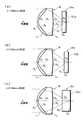
以下、図面を参照して本発明の実施形態について説明する。図1は本発明の実施例に係る光記録媒体用対物レンズの形状を模式的に示す図であり、図2は、この光記録媒体用対物レンズを用いた光ピックアップ装置の構成を示す図である。なお、各図面においてレンズの形状は全て模式的に表されている。 Hereinafter, embodiments of the present invention will be described with reference to the drawings. FIG. 1 is a diagram schematically showing the shape of an objective lens for an optical recording medium according to an embodiment of the present invention, and FIG. 2 is a diagram showing a configuration of an optical pickup device using the objective lens for an optical recording medium. is there. In each drawing, the shape of each lens is schematically represented.
この光ピックアップ装置では、図2に示すとおり、半導体レーザ1a〜1cから出力されたレーザ光11がハーフミラー6により反射され、コリメータレンズ7により略平行光とされ、光記録媒体用対物レンズ8により収束光とされて光記録媒体9の記録領域10上に照射される。この光ピックアップ装置が対象とする光記録媒体9は、下記3つの条件式(1)〜(3)の条件で使用されるものである。 In this optical pickup device, as shown in FIG. 2, the
NA1≧NA2>NA3・・・ (1)
λ1<λ2<λ3・・・ (2)
d1≦d2<d3・・・ (3)
ただし、
NA1・・・第1の光記録媒体に対応する開口数(第1開口数)
NA2・・・第2の光記録媒体に対応する開口数(第2開口数)
NA3・・・第3の光記録媒体に対応する開口数(第3開口数)
λ1・・・第1の光記録媒体に対応する使用光波長(第1波長)
λ2・・・第2の光記録媒体に対応する使用光波長(第2波長)
λ3・・・第3の光記録媒体に対応する使用光波長(第3波長)
d1・・・第1の光記録媒体の基板厚(第1基板厚)
d2・・・第2の光記録媒体の基板厚(第2基板厚)
d3・・・第3の光記録媒体の基板厚(第3基板厚)NA1 ≧ NA2> NA3 (1)
λ1 <λ2 <λ3 (2)
d1 ≦ d2 <d3 (3)
However,
NA1... Numerical aperture corresponding to the first optical recording medium (first numerical aperture)
NA2: Numerical aperture corresponding to the second optical recording medium (second numerical aperture)
NA3: Numerical aperture corresponding to the third optical recording medium (third numerical aperture)
λ1 used light wavelength (first wavelength) corresponding to the first optical recording medium
.lambda.2 used light wavelength (second wavelength) corresponding to the second optical recording medium.
λ3... used light wavelength (third wavelength) corresponding to the third optical recording medium
d1... substrate thickness of the first optical recording medium (first substrate thickness)
d2: Substrate thickness of the second optical recording medium (second substrate thickness)
d3... substrate thickness of the third optical recording medium (third substrate thickness)
ここでは、実施例に基づき、光記録媒体9は、第1の光記録媒体としてのAOD9a(開口数NA1=0.65、使用光波長λ1=408nm、基板厚d1=0.6mm)、第2の光記録媒体としてのDVD9b(開口数NA2=0.6、使用光波長λ2=658nm、基板厚d2=0.6mm)および第3の光記録媒体としてのCD9c(開口数NA3=0.51、使用光波長λ3=784nm、基板厚d3=1.2mm)を総称するものとして説明する。 Here, based on the embodiment, the optical recording medium 9 is an
半導体レーザ1aは、AOD用の、波長408nm(λ1)の可視域のレーザ光を出力する光源であり、半導体レーザ1bは、DVD用の、波長658nm(λ2)の可視域のレーザ光を出力する光源である。また、半導体レーザ1cは、CD−R(追記型光記録媒体)等のCD系用の(以下、これを代表してCDとして説明する)、波長784nm(λ3)の近赤外域のレーザ光を出力する光源である。半導体レーザ1a〜1cは、重複して出力されることを排除するものではないが、光記録媒体9がAOD9aであるか、DVD9bであるか、CD9cであるかに応じて、択一的に出力されることが好ましい。半導体レ−ザ1a、1bから出力されたレ−ザ光11は、プリズム2a、2bを介して、また、半導体レ−ザ1cから出力されたレ−ザ光11は、プリズム2bを介して、ハ−フミラ−6に照射されるようになっている。 The
また、コリメータレンズ7は、図2において模式的に示されたものであって1枚構成のものとは限られず、むしろ上記各波長の光について色収差が良好に補正されたものとすることが好ましい。 Further, the collimator lens 7 is schematically shown in FIG. 2 and is not limited to one having a single lens structure. Rather, it is preferable that the chromatic aberration is corrected well for the light of each wavelength. .
本実施形態の光ピックアップ装置では、所定位置(ターンテーブル上)に配されたAOD9a、DVD9bおよびCD9cのいずれの光記録媒体9についても、その記録領域10(AOD9a、DVD9bおよびCD9cの記録領域をそれぞれ10a、10b、10cとする)に、対応する波長の光が良好に収束されて、信号の記録・再生が可能となるように構成されている。図1(a)〜(c)はそれぞれ、光記録媒体9がAOD9a、DVD9bおよびCD9cとされている場合を示すものである。 In the optical pickup device of this embodiment, the recording area 10 (
記録領域10には信号情報を担持したピットがトラック状に配列されるようになっており、この記録領域10からの上記レーザ光11の反射光は信号情報を担持した状態で対物レンズ8およびコリメータレンズ7を介してハーフミラー6に入射し、このハーフミラー6を透過して4分割のフォトダイオード13に入射する。このフォトダイオード13では、分割された4つのダイオード位置の各受光量が電気信号の形態で得られるから、この受光量に基づき図示されない演算手段において所定の演算がなされ、データ信号、およびフォーカスとトラッキングの各エラー信号を得られることになる。 In the
なお、ハーフミラー6は光記録媒体9からの戻り光の光路に対して45°傾いた状態で挿入されているのでシリンドリカルレンズと同等の作用をなし、このハーフミラー6を透過した光ビームは非点収差を有することとなり、4分割のフォトダイオード13上におけるこの戻り光のビームスポットの形状に応じてフォーカスのエラー量が決定されることとなる。なお、上記コリメータレンズ7は状況に応じて省略することも可能であり、さらに半導体レーザ1a〜1cとハーフミラー6との間にグレーティングを挿入して3ビームによりトラッキングエラーを検出することも可能である。 Since the half mirror 6 is inserted in a state inclined by 45 ° with respect to the optical path of the return light from the optical recording medium 9, the half mirror 6 operates in the same manner as the cylindrical lens, and the light beam transmitted through the half mirror 6 is non-reflective. As a result, the amount of focus error is determined according to the shape of the beam spot of the return light on the four-divided
ところで、本実施形態の対物レンズ8の特徴は、図1および図2に示すとおり、互いに異なる材質により構成される2つのレンズを互いに接合してなり、この接合された面は所定の回折光学面により形成されている点にある。これらの特徴により、接合面での屈折および回折の作用を利用して、3つの互いに異なる波長の光について所望の使用条件(例えば結像倍率)で、対物レンズ8を使用することが可能となる。 By the way, as shown in FIGS. 1 and 2, the objective lens 8 of the present embodiment is characterized by joining two lenses made of different materials to each other, and the joined surface is a predetermined diffractive optical surface. It is in the point formed by. With these features, it is possible to use the objective lens 8 under desired use conditions (for example, imaging magnification) for light of three different wavelengths by utilizing the action of refraction and diffraction at the cemented surface. .
従来より、ディスク厚が互いに異なる2種類の光記録媒体を使用する場合に、回折光学面を設けることにより、対応する2つの波長の光のいずれについても球面収差量を最適化する手法が知られている。これらの光記録媒体では、主として保護層の厚さの違いにより、発生する球面収差の量が異なってくるが、回折光学面を設けることにより互いに異なる収束作用を有する構成とし収差補正機能を良好とすることができるので、いずれの光記録媒体についても所望の使用条件で、対物レンズを使用することができる。光源からの光をいずれも対物レンズに平行光束に近い状態で入射させ、光学系の配置選択の自由度を高めることも可能となる。 Conventionally, when two types of optical recording media having different disk thicknesses are used, a method of optimizing the amount of spherical aberration for any two corresponding wavelengths of light by providing a diffractive optical surface is known. ing. In these optical recording media, the amount of generated spherical aberration differs mainly due to the difference in the thickness of the protective layer. Therefore, the objective lens can be used under any desired use condition for any optical recording medium. It is also possible to increase the degree of freedom in selecting the arrangement of the optical system by allowing light from the light source to enter the objective lens in a state close to a parallel light flux.
本実施形態の対物レンズ8は、これを発展させ、3つの互いに異なる波長の光について所望の使用条件での設計を容易にするものである。回折光学面を備えた従来の2波長対応の光記録媒体用対物レンズとしては、最も簡易な構成としては1枚構成で一方の面が回折光学面とされていた。回折光学面の光源側または光記録媒体側のいずれか一方は空気となり、屈折率は固定値であった。 The objective lens 8 of the present embodiment is developed to facilitate the design of the light having three different wavelengths under a desired use condition. As a conventional objective lens for a two-wavelength optical recording medium equipped with a diffractive optical surface, the simplest configuration is a single lens configuration with one surface being a diffractive optical surface. Either the light source side or the optical recording medium side of the diffractive optical surface was air, and the refractive index was a fixed value.
これに対し、本実施形態では、3つの互いに異なる波長の光に対応させるため、波長による回折光学面での光の屈折および回折作用の変化に大きく影響する回折光学面に対する光源側と光記録媒体側の屈折率差に着目している。回折光学面に対する光源側と光記録媒体側の屈折率をいずれもパラメータとすることにより、各波長に対する回折光学面での光の屈折および回折作用を良好に制御することが容易となる。そのために、本実施形態の対物レンズ8は、回折光学面が接合面となるように、互いに異なる材質により構成される2つのレンズを互いに接合している。2つのレンズの屈折率を適切に設定することにより、3つの互いに異なる波長の光について、いずれの光も同じ使用条件で対物レンズ8を使用することも容易に可能となる。 On the other hand, in the present embodiment, the light source side and the optical recording medium with respect to the diffractive optical surface that greatly affect the refraction of the light on the diffractive optical surface and the change in the diffraction action according to the wavelength in order to correspond to light of three different wavelengths. We focus on the difference in refractive index on the side. By using both the refractive index of the light source side and the optical recording medium side with respect to the diffractive optical surface as parameters, it becomes easy to satisfactorily control the refraction and diffractive action of light on the diffractive optical surface for each wavelength. For this purpose, the objective lens 8 of the present embodiment joins two lenses made of different materials to each other so that the diffractive optical surface becomes a cemented surface. By appropriately setting the refractive indexes of the two lenses, it is possible to easily use the objective lens 8 under the same use conditions for any light of three different wavelengths.
特に、この光記録媒体用対物レンズ8に入射する3つの互いに異なる波長の光を、いずれの光も平行光束に近い状態で入射させるように構成されている場合には、コリメータレンズ7と対物レンズ8との距離を任意に設定することもでき、光路の折り曲げも含め、光学系の配置選択の自由度を高めることも容易に可能となり、好ましい。 In particular, in the case where light of three different wavelengths incident on the objective lens 8 for the optical recording medium is configured so that all the lights are incident in a state close to a parallel light flux, the collimator lens 7 and the objective lens The distance between the optical system and the optical system can be arbitrarily set, and the degree of freedom in selecting the arrangement of the optical system including bending of the optical path can be easily increased.
また、この対物レンズ8は接合レンズとされ、見かけ上は1枚のレンズとして取り扱うことができるので、例えばレンズ鏡筒などを追加する必要がなく、簡易な構成とすることができる。 Further, since the objective lens 8 is a cemented lens and can be handled as a single lens in appearance, it is not necessary to add a lens barrel or the like, for example, and a simple configuration can be achieved.
対物レンズ8の接合面の形状は、下記に示す非球面式により表される。 The shape of the cemented surface of the objective lens 8 is represented by the following aspheric expression.

また、この接合面に形成される回折光学面は、断面形状が鋸歯状のものとされることが好ましく、その位相差は下記に示す位相差関数により表される。「鋸歯状」とはいわゆるキノフォームと称される形状であるが、これに階段近似した形状をも含むものとする。図1および図2においては、回折光学面であることを示すために、実際の回折光学面の鋸歯形状よりも誇張して示している。この回折光学面により、波長をλ、回折光学面位相差関数をφとして、回折光にmλ×φ/(2π)の光路長が付加される。ここで、mは回折次数を表わす。 The diffractive optical surface formed on the joint surface preferably has a sawtooth cross-sectional shape, and the phase difference is represented by the phase difference function shown below. The “sawtooth shape” is a shape called a so-called kinoform, but includes a shape approximated by steps. In FIG. 1 and FIG. 2, in order to show that it is a diffractive optical surface, it is exaggerated from the sawtooth shape of the actual diffractive optical surface. The diffractive optical surface adds an optical path length of mλ × φ / (2π) to the diffracted light, where the wavelength is λ and the diffractive optical surface phase difference function is φ. Here, m represents the diffraction order.
なお、回折光学面の具体的な鋸歯形状のステップの高さは、使用する各波長の光に対する各次数の回折光の割合を考慮して設定する。また、回折光学面の最外径は、入射する3つの波長のレーザ光11の開口数とビーム径を勘案して適宜設定し得る。対物レンズ8に形成される回折光学面および非球面は、その面が作用する波長の光が、対応する記録領域10に良好に収差補正されて収束されるように、適宜設定されることが好ましい。 The specific height of the step of the sawtooth shape on the diffractive optical surface is set in consideration of the ratio of the diffracted light of each order to the light of each wavelength used. In addition, the outermost diameter of the diffractive optical surface can be appropriately set in consideration of the numerical aperture and beam diameter of the
また、この回折光学面は、AOD用の波長408nm(λ1)のレーザ光に対して回折光の光量が最大となる回折次数と、DVD用の波長658nm(λ2)のレーザ光に対して回折光の光量が最大となる回折次数とが互いに異なるように、かつ、AOD用の波長408nm(λ1)のレーザ光に対して回折光の光量が最大となる回折次数と、CD用の波長784nm(λ3)のレーザ光に対して回折光の光量が最大となる回折次数とが互いに異なるように、作用する形状とされることが好ましい。 In addition, this diffractive optical surface has a diffraction order that maximizes the amount of diffracted light with respect to laser light with a wavelength of 408 nm (λ1) for AOD and diffracted light with respect to laser light with a wavelength of 658 nm (λ2) for DVD. The diffraction order at which the light quantity of the diffracted light becomes the maximum with respect to the laser light having the wavelength 408 nm (λ1) for AOD and the wavelength 784 nm (λ3 for CD) It is preferable that the shape behave so that the diffraction order at which the light quantity of the diffracted light is maximum differs from that of the laser light.
このようにAOD用のレーザ光とDVD用のレーザ光、ならびに、AOD用のレーザ光とCD用のレーザ光に対して、互いに異なる回折次数の光を利用することにより、3つの互いに異なる波長の光について、互いに性能に悪影響を及ぼすことなく所望の位置に収束させることができる。実施例では、AOD用の波長408nm(λ1)のレーザ光に対しては0次の回折光の光量が最大となり、DVD用の波長658nm(λ2)およびCD用の波長784nm(λ3)のレーザ光に対しては、各々1次の回折光の光量が最大となるように設定されている。 Thus, by using light of different diffraction orders for the laser light for AOD and the laser light for DVD, and the laser light for AOD and the laser light for CD, three different wavelengths can be obtained. The light can be converged to a desired position without adversely affecting the performance of each other. In the embodiment, the amount of 0th-order diffracted light is maximum for laser light having a wavelength of 408 nm (λ1) for AOD, and laser light having a wavelength of 658 nm (λ2) for DVD and a wavelength of 784 nm (λ3) for CD. Is set so that the amount of the first-order diffracted light is maximized.
ところで、上述のとおり対物レンズ8は、回折光学面に対する光源側と光記録媒体側の屈折率、すなわち2つのレンズの屈折率を適切に設定することにより、波長による回折光学面での光の屈折および回折作用の変化を利用し3つの互いに異なる波長の光に対応させるものであるが、レンズ材質の組合わせによっては、特定の波長の光において2つのレンズの屈折率が等しくなる場合がある。この場合には、この波長の光に対する回折光学面の回折作用は0となり(0次回折光が100%となる)、この波長の光に対しては、対物レンズ8はあたかも均質な1枚のレンズであるかのように作用し、その光屈折作用のみによりこの光は収束せしめられることになる。 Incidentally, as described above, the objective lens 8 refracts light on the diffractive optical surface depending on the wavelength by appropriately setting the refractive indexes of the light source side and the optical recording medium side with respect to the diffractive optical surface, that is, the refractive indexes of the two lenses. The change in diffraction action is used to correspond to three different wavelengths of light, but depending on the combination of lens materials, the refractive index of the two lenses may be equal for specific wavelengths of light. In this case, the diffractive action of the diffractive optical surface with respect to light of this wavelength is 0 (0th-order diffracted light is 100%), and for this wavelength of light, the objective lens 8 is as if it is a homogeneous single lens. The light is converged only by the photorefractive action.
実際上は、0次回折光が100%とまではならなくとも、例えば、最も波長が小さく、高い解像度が要求されるAOD用の波長408nm(λ1)のレーザ光に対して、2つのレンズ材質の屈折率差を小さくし0次回折光の割合を高くした場合にも、略同様の作用を得ることができる。 In practice, even if the 0th-order diffracted light does not reach 100%, for example, two lens materials are used for laser light having a wavelength of 408 nm (λ1) for AOD that requires the smallest wavelength and high resolution. When the refractive index difference is reduced and the ratio of the 0th-order diffracted light is increased, substantially the same operation can be obtained.
そこで、この対物レンズ8において、下記条件式(4)〜(6)となるようにh1、h2およびh3を定義したとき、下記条件式(7)または(8)が成立するように構成することが好ましい。 Therefore, in the objective lens 8, when h1, h2, and h3 are defined so as to satisfy the following conditional expressions (4) to (6), the following conditional expression (7) or (8) is satisfied. Is preferred.
h1=λ1/|N1λ1−N2λ1|・・・ (4)
(ただし、N1λ1−N2λ1=0となるときは、h1=∞とする。)
h2=λ2/|N1λ2−N2λ2|・・・ (5)
(ただし、N1λ2−N2λ2≠0)
h3=λ3/|N1λ3−N2λ3|・・・ (6)
(ただし、N1λ3−N2λ3≠0)
h2/h1≦0.5・・・ (7)
h3/h1≦0.5・・・ (8)
(ただし、条件式(7)および(8)において、h1=∞のときは、h2/h1=0、h3/h1=0とする。)
ただし、
N1λ1・・・前記2つのレンズのうち光源側に配されるレンズの材質の前記第1波長の光に対する屈折率
N1λ2・・・前記2つのレンズのうち光源側に配されるレンズの材質の前記第2波長の光に対する屈折率
N1λ3・・・前記2つのレンズのうち光源側に配されるレンズの材質の前記第3波長の光に対する屈折率
N2λ1・・・前記2つのレンズのうち光記録媒体側に配されるレンズの材質の前記第1波長の光に対する屈折率
N2λ2・・・前記2つのレンズのうち光記録媒体側に配されるレンズの材質の前記第2波長の光に対する屈折率
N2λ3・・・前記2つのレンズのうち光記録媒体側に配されるレンズの材質の前記第3波長の光に対する屈折率h1 = λ1 / | N1λ1 −N2λ1 | (4)
(However, when N1λ1 −N2λ1 = 0, it is assumed that h1 = ∞.)
h2 = λ2 / | N1λ2- N2λ2 | (5)
(However, N1λ2 −N2λ2 ≠ 0)
h3 = λ3 / | N1λ3- N2λ3 | (6)
(However, N1λ3 -N2λ3 ≠ 0)
h2 / h1 ≦ 0.5 (7)
h3 / h1 ≦ 0.5 (8)
(However, in conditional expressions (7) and (8), when h1 = ∞, h2 / h1 = 0 and h3 / h1 = 0)
However,
N1λ1 ... Refractive index of the material of the lens disposed on the light source side of the two lenses with respect to the light of the first wavelength N1λ2 ... The material of the lens disposed on the light source side of the two lenses Refractive index for light of the second wavelength N1λ3 ... Refractive index for light of the third wavelength of the material of the lens disposed on the light source side of the two lenses N2λ1 . Of these, the refractive index of the material of the lens disposed on the optical recording medium side with respect to the light of the first wavelength N2λ2 ... Of the second wavelength of the material of the lens disposed on the optical recording medium side of the two lenses. Refractive index with respect to light N2λ3 ... Refractive index with respect to light of the third wavelength of the material of the lens arranged on the optical recording medium side of the two lenses.
条件式(7)を満足することにより、第2波長としてのDVD用の波長658nm(λ2)のレーザ光に対して1次の回折光量が最大になるように鋸歯形状のステップ高さを設定した場合に、第1波長としてのAOD用の波長408nm(λ1)のレーザ光に対しては0次の回折光の光量が最大となる。また、条件式(8)を満足することにより、第3波長としてのCD用の波長784nm(λ3)のレーザ光に対して1次の回折光量が最大になるように鋸歯形状のステップ高さを設定した場合に、第1波長としてのAOD用の波長408nm(λ1)のレーザ光に対しては0次の回折光の光量が最大となる。h2/h1およびh3/h1の値は、いずれも0に近づくほどAOD用の波長408nm(λ1)のレーザ光の0次の回折光の光量が増し望ましいが、条件式(7)および(8)の値はその許容範囲を示すものである。 By satisfying conditional expression (7), the step height of the sawtooth shape is set so that the first-order diffracted light quantity becomes maximum with respect to the laser beam having the wavelength 658 nm (λ2) for DVD as the second wavelength. In this case, the amount of 0th-order diffracted light is maximized with respect to laser light having a wavelength of 408 nm (λ1) for AOD as the first wavelength. Further, by satisfying the conditional expression (8), the step height of the sawtooth shape is set so that the first-order diffracted light quantity becomes maximum with respect to the laser light having the wavelength 784 nm (λ3) for CD as the third wavelength. When set, the amount of 0th-order diffracted light is maximized for laser light having a wavelength of 408 nm (λ1) for AOD as the first wavelength. It is desirable that the values of h2 / h1 and h3 / h1 both increase the light amount of the 0th-order diffracted light of the laser light having a wavelength of 408 nm (λ1) for AOD as it approaches 0, but conditional expressions (7) and (8) The value of indicates the allowable range.
このように3つの使用波長に対して、0次または1次の回折光の光量が最大となるように回折光学面を設定する構成は、鋸歯形状のステップが浅く、製造が比較的容易であり効果が高い。 In this way, the configuration in which the diffractive optical surface is set so that the light amount of the 0th-order or 1st-order diffracted light is maximized with respect to the three used wavelengths is relatively easy to manufacture because the sawtooth step is shallow. High effect.
また、この光記録媒体用対物レンズ8において、光源側の面および光記録媒体側の面の少なくとも一方が、所定の非球面とされていることが好ましい。非球面の形状は上述した接合面のものと同様の非球面式により表される。このような非球面を形成することにより、いずれの光記録媒体9についても収差補正を良好とし、確実にフォーカシングをなし記録・再生が良好に行われるように構成することができる。 In the objective lens 8 for optical recording medium, it is preferable that at least one of the light source side surface and the optical recording medium side surface is a predetermined aspherical surface. The shape of the aspherical surface is represented by the same aspherical expression as that of the above-described joint surface. By forming such an aspherical surface, any optical recording medium 9 can be configured so that aberration correction is good, focusing is performed reliably, and recording and reproduction are performed satisfactorily.
ここで、光記録媒体用対物レンズ8の実施例について説明する。この対物レンズ8は、光源側レンズL1と光記録媒体側レンズL2の接合レンズとされ、接合面、光源側レンズL1の光源側の面、および光記録媒体側レンズL2の光記録媒体側の面のいずれもが、非球面とされている。この対物レンズ8は、光記録媒体9としてのAOD9a、DVD9bおよびCD9cの記録領域10a、10b、10cに、各使用光λ=408nm(λ1)、λ=658nm(λ2)、およびλ=784nm(λ3)を良好に収束させるものである。また、この対物レンズ8は、これら各使用光がいずれも略平行光束として入射される無限共役の光学系とされている。また、各使用光は光記録媒体9に応じて、択一的に出力される。Here, an example of the objective lens 8 for an optical recording medium will be described. The objective lens 8 is the light source side lens L1 and the optical recording medium-side lens L2 of the cemented lens, the bonding surface, the light source-side surface of the light source side lens L1, and the optical recording medium-side lens L2 optical recording All the surfaces on the medium side are aspherical surfaces. This objective lens 8 is used for recording
下記表1の上段に、この実施例に係る対物レンズ8のレンズデータの具体的数値として、曲率半径(mm)(ただし、非球面については表2に記載している)、λ=408nm(λ1)、λ=658nm(λ2)、およびλ=784nm(λ3)に対する面間隔(mm)、ならびに上記各波長の光に対する屈折率を示す。なお、曲率半径、面間隔および屈折率に対応させた数字は光源側から順次増加するようになっている。また、表1の下段に、光記録媒体9としてAOD9a、DVD9bおよびCD9cをセットした各場合における使用波長について、この実施例に係る対物レンズ8の絞り径(mm)、焦点距離(mm)、開口数NA、および光源位置の各値を示す。 In the upper part of Table 1 below, as specific numerical values of the lens data of the objective lens 8 according to this example, the radius of curvature (mm) (however, the aspherical surface is described in Table 2), λ = 408 nm (λ1 ), Λ = 658 nm (λ2), and surface spacing (mm) for λ = 784 nm (λ3), and the refractive index for light of each of the above wavelengths. The numbers corresponding to the radius of curvature, the surface interval, and the refractive index are sequentially increased from the light source side. Also, in the lower part of Table 1, the aperture diameter (mm), focal length (mm), aperture of the objective lens 8 according to this example are shown for the wavelengths used in each case where
また、下記表2に、この実施例に係る対物レンズ8の各非球面の非球面係数を示し、下記表3に、この実施例に係る対物レンズ8の回折光学面の位相差関数係数を示す。この回折光学面は断面形状が鋸歯形状の同心円格子からなり、上述のように、AOD用の波長408nm(λ1)のレーザ光に対しては0次の回折光の光量が最大となり、DVD用の波長658nm(λ2)のレーザ光に対しては1次の回折光の光量が最大となり、CD用の波長784nm(λ3)のレーザ光に対しては1次の回折光の光量が最大となるように設定されている。 Table 2 below shows the aspheric coefficients of each aspheric surface of the objective lens 8 according to this embodiment, and Table 3 below shows the phase difference function coefficients of the diffractive optical surface of the objective lens 8 according to this embodiment. . This diffractive optical surface is a concentric circular lattice with a sawtooth cross-sectional shape. As described above, the amount of 0th-order diffracted light is maximum for laser light with a wavelength of 408 nm (λ1) for AOD. The amount of first-order diffracted light is maximized for laser light with a wavelength of 658 nm (λ2), and the amount of first-order diffracted light is maximized for laser light with a wavelength of 784 nm (λ3) for CD. Is set to
また、この実施例は条件式(1)〜(3)、(7)、(8)を全て満足している。λ1=408nmにおいて、N1λ1=1.55869、N2λ1=1.55636より、h1=175107.296nmとなる。λ2=658nmにおいて、N1λ2=1.52426、N2λ2=1.54076より、h2=39878.788nmとなる。λ3=784nmにおいて、N1λ3=1.52127、N2λ3=1.53704より、h3=49714.648nmとなる。したがって、条件式(7)に対応する値はh2/h1=0.23となり、条件式(8)に対応する値はh3/h1=0.28となる。In addition, this example satisfies all the conditional expressions (1) to (3), (7), and (8). At λ1 = 408 nm, h1 = 175107.296 nm from N1λ1 = 1.55869 and N2λ1 = 1.55636. At λ2 = 658 nm, H2 = 39878.788 nm from N1λ2 = 1.52426 and N2λ2 = 1.54076. At λ3 = 784 nm, H3 = 49714.648 nm from N1λ3 = 1.52127 and N2λ3 = 1.53704. Therefore, the value corresponding to the conditional expression (7) is h2 / h1 = 0.23, and the value corresponding to the conditional expression (8) is h3 / h1 = 0.28.
なお、本発明の光記録媒体用対物レンズとしては上述したものに限られず種々の態様の変更が可能である。また、本発明の光ピックアップ装置としても、同様に種々の態様の変更が可能である。 The objective lens for an optical recording medium of the present invention is not limited to that described above, and various modifications can be made. Also, various modifications of the optical pickup device of the present invention can be made in the same manner.
例えば、対物レンズを形成する材料として、例えばプラスチック材料を使用することで、軽量、安価なものとすることができる。また、対物レンズの一方のレンズ材料として、熱や光によって硬化する樹脂を使用し、いわゆるレプリカ加工法による複合型非球面レンズを用いることで、回折光学面が形成された接合非球面レンズを安価に製造することができる。例えば、上記実施例のものでは、光記録媒体側レンズL2の光源側の回折光学面に紫外線硬化型の樹脂を塗設し、該樹脂を所定の金型によって圧着しながら所定の紫外線を照射することにより、光源側レンズL1を形成するとよい。For example, by using, for example, a plastic material as a material for forming the objective lens, it can be made light and inexpensive. In addition, by using a resin that cures by heat or light as one lens material of the objective lens, and using a composite aspheric lens by the so-called replica processing method, a cemented aspheric lens with a diffractive optical surface is inexpensive. Can be manufactured. For example, those of the above embodiment, by coating an ultraviolet curable resin on the diffractive optical surface of the light source side of the optical recording medium-side lens L2, a predetermined ultraviolet while crimping the resin by a predetermined mold irradiation by, it may be formed of the light source side lens L1.
また、上記実施例では、DVD用の波長658nm(λ2)のレーザ光とCD用の波長784nm(λ3)のレーザ光に対して、1次の回折光の光量が最大となるように回折光学面が構成されているが、第2波長λ2の光に対する回折光の光量が最大になる回折次数と、第3波長λ3の光に対する回折光の光量が最大になる回折次数とが、異なる次数となるように回折光学面を設定してもよい。 In the above embodiment, the diffractive optical surface is designed so that the light quantity of the first-order diffracted light is maximized with respect to the laser light having a wavelength of 658 nm (λ2) for DVD and the laser light having a wavelength of 784 nm (λ3) for CD. However, the diffraction order at which the amount of diffracted light with respect to the light with the second wavelength λ2 is maximized is different from the diffraction order with the maximum amount of diffracted light with respect to the light with the third wavelength λ3. A diffractive optical surface may be set as described above.
また、対物レンズの回折光学面は、上記以外の回折次数の回折光の光量が最大となるように設定されていてもよい。この場合も、いずれの波長の光に対しても、所定次数の回折光の光量が多く出力されることが好ましく、その光量がそれぞれほぼ100%となれば最も効果が高い。 Further, the diffractive optical surface of the objective lens may be set so that the amount of diffracted light having a diffraction order other than the above is maximized. Also in this case, it is preferable that a large amount of diffracted light of a predetermined order is output for light of any wavelength, and the highest effect is obtained when the amount of light is approximately 100%.
また、上述した対物レンズにおいては対物レンズの全ての面を非球面として収差補正効果を高めているが、非球面を用いず、球面によるレンズとされていても良い。また、対物レンズの光源側の面および光記録媒体側の面のうちいずれか一方の面のみを、非球面とすることも可能である。 In the objective lens described above, all surfaces of the objective lens are aspherical to enhance the aberration correction effect. However, the aspherical surface may be used instead of the aspherical surface. In addition, only one of the surface on the light source side and the surface on the optical recording medium side of the objective lens can be an aspherical surface.
また、本発明の光記録媒体用対物レンズおよび光ピックアップ装置において、実施例ではいずれの光記録媒体に対応する波長の光も、略平行とされた状態で対物レンズに入射させる構成としているが、光源からの光が対物レンズにやや発散あるいはやや集束された状態で入射させることが許容される場合には、本発明の対物レンズに対し、1つないし3つの光記録媒体に対応する光を、このように入射させる構成を除外するものではない。 Further, in the objective lens for optical recording medium and the optical pickup device of the present invention, in the embodiment, light having a wavelength corresponding to any optical recording medium is configured to enter the objective lens in a substantially parallel state. When the light from the light source is allowed to enter the objective lens in a slightly divergent or slightly focused state, the light corresponding to one to three optical recording media is applied to the objective lens of the present invention. Such a configuration for incidence is not excluded.
また、本発明の光記録媒体用対物レンズおよび光ピックアップ装置において、記録・再生対象となる光記録媒体としてはAOD、DVDおよびCDという組合わせに限られない。条件式(1)〜(3)を満足するように設定された光記録媒体を、共通の光ピックアップ装置で記録・再生する場合に本発明を適用できる。例えば、上記組合わせのうちAODに代えて、ブルーレイディスク(開口数0.85、基板厚0.1mm、使用光波長405nm程度)を用いることができる。 In the objective lens for optical recording medium and the optical pickup device of the present invention, the optical recording medium to be recorded / reproduced is not limited to the combination of AOD, DVD and CD. The present invention can be applied to the case where an optical recording medium set to satisfy the conditional expressions (1) to (3) is recorded / reproduced by a common optical pickup device. For example, instead of AOD in the above combination, a Blu-ray disc (numerical aperture 0.85, substrate thickness 0.1 mm, use light wavelength about 405 nm) can be used.
また、光記録媒体を上記実施例と同じくAOD、DVD、およびCDとした場合にも、その使用光波長は、実施例のものに限られない。AODの使用光波長408nm、DVDの使用光波長658nmおよびCDの使用光波長784nm以外の波長の光であっても、それぞれの光記録媒体の規格を満たすものであればその範囲内で任意に設定することができる。また、開口数、基板厚に付いても同様である。 Also, when the optical recording medium is AOD, DVD, and CD as in the above embodiment, the light wavelength used is not limited to that in the embodiment. Even light with a wavelength other than the AOD operating wavelength 408 nm, DVD operating wavelength 658 nm, and CD operating wavelength 784 nm can be set as long as it meets the standards for each optical recording medium. can do. The same applies to the numerical aperture and the substrate thickness.
また、本発明の光記録媒体用対物レンズおよび光ピックアップ装置の延長上に位置する概念としては、必ずしも光記録媒体の種類が3種の場合の適用に限られるものではなく、2種の光記録媒体に対してのみ光源からの光を対物レンズに平行光束に近い状態で入射させるという条件が課されるような場合においても、より光学性能の優れた光記録媒体用対物レンズが容易に設計可能となり、その実用上の効果は極めて大きいものがある。また、4種以上の光記録媒体に対しても、本発明の光記録媒体用対物レンズの適用を妨げるものではない。 Further, the concept positioned on the extension of the objective lens for an optical recording medium and the optical pickup device of the present invention is not necessarily limited to the application in the case where there are three types of optical recording media, but two types of optical recording. An objective lens for optical recording media with superior optical performance can be easily designed even when the condition that light from a light source is incident on the objective lens in a state close to a parallel light flux only on the medium is imposed. Therefore, the practical effect is extremely large. Moreover, application of the objective lens for an optical recording medium of the present invention is not prevented even for four or more types of optical recording media.
また、上記説明に用いた光ピックアップ装置では互いに異なる波長の光を出力する3つの光源を設けているが、光源として、2つの異なる波長の光を近接した出力口から出力し得る1つの光源を用いるようにしても良い。この場合には、例えば図2のプリズム2a、2bに代えて、1つのプリズムを配した構成としてもよい。また、この光ピックアップ装置において、対物レンズの光源側に絞りや波長選択性のある開口制限素子が配設されていてもよい。 The optical pickup device used in the above description includes three light sources that output light of different wavelengths. However, as the light source, one light source that can output light of two different wavelengths from adjacent output ports is provided. It may be used. In this case, for example, one prism may be provided instead of the
1a、1b、1c 半導体レーザ
2a、2b プリズム
6 ハーフミラー
7 コリメータレンズ
8 対物レンズ
9 光記録媒体
9a AOD
9b DVD
9c CD
10、10a、10b、10c 記録領域
11 レーザ光
13 フォトダイオード
L1、L2 レンズ
R1〜R5 レンズ面(ただし、R4、R5は光記録媒体の保護層)
D1〜D4 軸上面間隔1a, 1b,
9b DVD
9c CD
10, 10a, 10b,
D1 to D4 axial distance
Claims (6)
Translated fromJapanese互いに異なる材質により構成される2つのレンズを互いに接合してなり、該接合された面は所定の回折光学面により形成されてなり、
前記所定の回折光学面は断面形状が鋸歯状とされ、
前記第1の光記録媒体の使用光である第1波長の光に対して回折光の光量が最大となる回折次数と、前記第2の光記録媒体の使用光である第2波長の光に対して回折光の光量が最大となる回折次数とが互いに異なるように、
かつ、前記第1波長の光に対して回折光の光量が最大となる回折次数と、前記第3の光記録媒体の使用光である第3波長の光に対して回折光の光量が最大となる回折次数とが互いに異なるように作用する形状とされていることを特徴とする光記録媒体用対物レンズ。
NA1≧NA2>NA3・・・ (1)
λ1<λ2<λ3・・・ (2)
d1≦d2<d3・・・ (3)
ただし、
NA1・・・前記第1の光記録媒体に対応する開口数(第1開口数)
NA2・・・前記第2の光記録媒体に対応する開口数(第2開口数)
NA3・・・前記第3の光記録媒体に対応する開口数(第3開口数)
λ1・・・前記第1の光記録媒体に対応する使用光波長(第1波長)
λ2・・・前記第2の光記録媒体に対応する使用光波長(第2波長)
λ3・・・前記第3の光記録媒体に対応する使用光波長(第3波長)
d1・・・前記第1の光記録媒体の基板厚(第1基板厚)
d2・・・前記第2の光記録媒体の基板厚(第2基板厚)
d3・・・前記第3の光記録媒体の基板厚(第3基板厚)When information is recorded or reproduced, the corresponding numerical aperture, wavelength of light used, and substrate thickness are set so as to satisfy the following three conditional expressions (1) to (3). In the objective lens for an optical recording medium for converging the used light to a desired position for each of the three optical recording media,
Be joined together two lenses composed of different materials, the bonded surfacesRi Na is formed by a predetermined diffractive opticalsurface,
The predetermined diffractive optical surface has a sawtooth cross-sectional shape,
The diffraction order that maximizes the amount of diffracted light with respect to light of the first wavelength that is light used by the first optical recording medium and light of the second wavelength that is light used by the second optical recording medium On the other hand, so that the diffraction orders at which the amount of diffracted light is maximum are different from each other,
The diffraction order at which the amount of diffracted light is maximum with respect to the light of the first wavelength, and the amount of light of diffracted light is maximum with respect to the light of the third wavelength that is the light used by the third optical recording medium. An objective lens for an optical recording medium, characterized in that thediffraction orders have different shapes .
NA1 ≧ NA2> NA3 (1)
λ1 <λ2 <λ3 (2)
d1 ≦ d2 <d3 (3)
However,
NA1... Numerical aperture corresponding to the first optical recording medium (first numerical aperture)
NA2: Numerical aperture corresponding to the second optical recording medium (second numerical aperture)
NA3... Numerical aperture corresponding to the third optical recording medium (third numerical aperture)
λ1 used light wavelength (first wavelength) corresponding to the first optical recording medium
.lambda.2 used light wavelength (second wavelength) corresponding to the second optical recording medium.
λ3... used light wavelength (third wavelength) corresponding to the third optical recording medium
d1... substrate thickness of the first optical recording medium (first substrate thickness)
d2: Substrate thickness of the second optical recording medium (second substrate thickness)
d3: Substrate thickness of the third optical recording medium (third substrate thickness)
h1=λ1/|N1h1 = λ1 / | N1λ1λ1−N2-N2λ1λ1|・・・ (4)・ ・ ・ ・ ・ ・ (4)
(ただし、N1(However, N1λ1λ1−N2-N2λ1λ1=0となるときは、h1=∞とする。)When = 0, h1 = ∞. )
h2=λ2/|N1h2 = λ2 / | N1λ2λ2−N2-N2λ2λ2|・・・ (5)| (5)
(ただし、N1(However, N1λ2λ2−N2-N2λ2λ2≠0)≠ 0)
h3=λ3/|N1h3 = λ3 / | N1λ3λ3−N2-N2λ3λ3|・・・ (6)・ ・ ・ ・ ・ ・ (6)
(ただし、N1(However, N1λ3λ3−N2-N2λ3λ3≠0)≠ 0)
h2/h1≦0.5・・・ (7)h2 / h1 ≦ 0.5 (7)
h3/h1≦0.5・・・ (8)h3 / h1 ≦ 0.5 (8)
(ただし、条件式(7)および(8)において、h1=∞のときは、h2/h1=0、h3/h1=0とする。)(However, in conditional expressions (7) and (8), when h1 = ∞, h2 / h1 = 0 and h3 / h1 = 0)
ただし、However,
N1N1λ1λ1・・・前記2つのレンズのうち光源側に配されるレンズの材質の前記第1波長の光に対する屈折率... The refractive index of the material of the lens arranged on the light source side of the two lenses with respect to the light of the first wavelength
N1N1λ2λ2・・・前記2つのレンズのうち光源側に配されるレンズの材質の前記第2波長の光に対する屈折率... The refractive index of the material of the lens disposed on the light source side of the two lenses with respect to the light of the second wavelength
N1N1λ3λ3・・・前記2つのレンズのうち光源側に配されるレンズの材質の前記第3波長の光に対する屈折率... The refractive index of the material of the lens disposed on the light source side of the two lenses with respect to the light of the third wavelength
N2N2λ1λ1・・・前記2つのレンズのうち光記録媒体側に配されるレンズの材質の前記第1波長の光に対する屈折率... The refractive index of the material of the lens disposed on the optical recording medium side of the two lenses with respect to the light of the first wavelength
N2N2λ2λ2・・・前記2つのレンズのうち光記録媒体側に配されるレンズの材質の前記第2波長の光に対する屈折率... The refractive index of the material of the lens disposed on the optical recording medium side of the two lenses with respect to the light of the second wavelength
N2N2λ3λ3・・・前記2つのレンズのうち光記録媒体側に配されるレンズの材質の前記第3波長の光に対する屈折率... The refractive index of the material of the lens disposed on the optical recording medium side of the two lenses with respect to the light of the third wavelength
互いに異なる材質により構成される2つのレンズを互いに接合してなり、該接合された面は所定の回折光学面により形成されてなり、
下記条件式(4)〜(6)となるようにh1、h2およびh3を定義したとき、下記条件式(7)または(8)が成立するように構成されていることを特徴とする光記録媒体用対物レンズ。
NA1≧NA2>NA3・・・ (1)
λ1<λ2<λ3・・・ (2)
d1≦d2<d3・・・ (3)
ただし、
NA1・・・前記第1の光記録媒体に対応する開口数(第1開口数)
NA2・・・前記第2の光記録媒体に対応する開口数(第2開口数)
NA3・・・前記第3の光記録媒体に対応する開口数(第3開口数)
λ1・・・前記第1の光記録媒体に対応する使用光波長(第1波長)
λ2・・・前記第2の光記録媒体に対応する使用光波長(第2波長)
λ3・・・前記第3の光記録媒体に対応する使用光波長(第3波長)
d1・・・前記第1の光記録媒体の基板厚(第1基板厚)
d2・・・前記第2の光記録媒体の基板厚(第2基板厚)
d3・・・前記第3の光記録媒体の基板厚(第3基板厚)
h1=λ1/|N1λ1−N2λ1|・・・ (4)
(ただし、N1λ1−N2λ1=0となるときは、h1=∞とする。)
h2=λ2/|N1λ2−N2λ2|・・・ (5)
(ただし、N1λ2−N2λ2≠0)
h3=λ3/|N1λ3−N2λ3|・・・ (6)
(ただし、N1λ3−N2λ3≠0)
h2/h1≦0.5・・・ (7)
h3/h1≦0.5・・・ (8)
(ただし、条件式(7)および(8)において、h1=∞のときは、h2/h1=0、h3/h1=0とする。)
ただし、
N1λ1・・・前記2つのレンズのうち光源側に配されるレンズの材質の前記第1波長の光に対する屈折率
N1λ2・・・前記2つのレンズのうち光源側に配されるレンズの材質の前記第2波長の光に対する屈折率
N1λ3・・・前記2つのレンズのうち光源側に配されるレンズの材質の前記第3波長の光に対する屈折率
N2λ1・・・前記2つのレンズのうち光記録媒体側に配されるレンズの材質の前記第1波長の光に対する屈折率
N2λ2・・・前記2つのレンズのうち光記録媒体側に配されるレンズの材質の前記第2波長の光に対する屈折率
N2λ3・・・前記2つのレンズのうち光記録媒体側に配されるレンズの材質の前記第3波長の光に対する屈折率When information is recorded or reproduced, the corresponding numerical aperture, wavelength of light used, and substrate thickness are set so as to satisfy the following three conditional expressions (1) to (3). In the objective lens for an optical recording medium for converging the used light to a desired position for each of the three optical recording media,
Two lenses made of different materials are bonded to each other, and the bonded surface is formed by a predetermined diffractive optical surface,
The following conditional expression (4) to (6) and a way when defining the h1, h2 and h3,light you characterized in that the following conditional expression (7) or (8) is configured to hold Objective lens for recording media.
NA1 ≧ NA2> NA3 (1)
λ1 <λ2 <λ3 (2)
d1 ≦ d2 <d3 (3)
However,
NA1... Numerical aperture corresponding to the first optical recording medium (first numerical aperture)
NA2: Numerical aperture corresponding to the second optical recording medium (second numerical aperture)
NA3... Numerical aperture corresponding to the third optical recording medium (third numerical aperture)
λ1 used light wavelength (first wavelength) corresponding to the first optical recording medium
.lambda.2 used light wavelength (second wavelength) corresponding to the second optical recording medium.
λ3... used light wavelength (third wavelength) corresponding to the third optical recording medium
d1... substrate thickness of the first optical recording medium (first substrate thickness)
d2: Substrate thickness of the second optical recording medium (second substrate thickness)
d3: Substrate thickness of the third optical recording medium (third substrate thickness)
h1 = λ1 / | N1λ1 −N2λ1 | (4)
(However, when N1λ1 −N2λ1 = 0, it is assumed that h1 = ∞.)
h2 = λ2 / | N1λ2- N2λ2 | (5)
(However, N1λ2 −N2λ2 ≠ 0)
h3 = λ3 / | N1λ3- N2λ3 | (6)
(However, N1λ3 -N2λ3 ≠ 0)
h2 / h1 ≦ 0.5 (7)
h3 / h1 ≦ 0.5 (8)
(However, in conditional expressions (7) and (8), when h1 = ∞, h2 / h1 = 0 and h3 / h1 = 0)
However,
N1λ1 ... Refractive index of the material of the lens disposed on the light source side of the two lenses with respect to the light of the first wavelength N1λ2 ... The material of the lens disposed on the light source side of the two lenses Refractive index for light of the second wavelength N1λ3 ... Refractive index for light of the third wavelength of the material of the lens disposed on the light source side of the two lenses N2λ1 . Of these, the refractive index of the material of the lens disposed on the optical recording medium side with respect to the light of the first wavelength N2λ2 ... Of the second wavelength of the material of the lens disposed on the optical recording medium side of the two lenses. Refractive index with respect to light N2λ3 ... Refractive index with respect to light of the third wavelength of the material of the lens arranged on the optical recording medium side of the two lenses.
Priority Applications (2)
| Application Number | Priority Date | Filing Date | Title |
|---|---|---|---|
| JP2004105252AJP4315440B2 (en) | 2003-08-21 | 2004-03-31 | Objective lens for optical recording medium and optical pickup device using the same |
| US10/922,958US7457223B2 (en) | 2003-08-21 | 2004-08-23 | Objective lens for optical recording media and optical pickup device using it |
Applications Claiming Priority (2)
| Application Number | Priority Date | Filing Date | Title |
|---|---|---|---|
| JP2003297756 | 2003-08-21 | ||
| JP2004105252AJP4315440B2 (en) | 2003-08-21 | 2004-03-31 | Objective lens for optical recording medium and optical pickup device using the same |
Publications (2)
| Publication Number | Publication Date |
|---|---|
| JP2005100586A JP2005100586A (en) | 2005-04-14 |
| JP4315440B2true JP4315440B2 (en) | 2009-08-19 |
Family
ID=34197176
Family Applications (1)
| Application Number | Title | Priority Date | Filing Date |
|---|---|---|---|
| JP2004105252AExpired - Fee RelatedJP4315440B2 (en) | 2003-08-21 | 2004-03-31 | Objective lens for optical recording medium and optical pickup device using the same |
Country Status (2)
| Country | Link |
|---|---|
| US (1) | US7457223B2 (en) |
| JP (1) | JP4315440B2 (en) |
Families Citing this family (15)
| Publication number | Priority date | Publication date | Assignee | Title |
|---|---|---|---|---|
| JP4349520B2 (en)* | 2003-10-27 | 2009-10-21 | フジノン株式会社 | Objective optical system for optical recording medium and optical pickup device using the same |
| JP2006012394A (en)* | 2004-05-27 | 2006-01-12 | Konica Minolta Opto Inc | Optical system, optical pickup device, and optical disk driving device |
| JP2006073076A (en)* | 2004-09-01 | 2006-03-16 | Fujinon Corp | Object optical system for optical recording medium, and optical pickup device using the same |
| JP4437731B2 (en)* | 2004-10-08 | 2010-03-24 | フジノン株式会社 | Optical pickup optical system and optical pickup device using the same |
| JP2006134492A (en) | 2004-11-08 | 2006-05-25 | Fujinon Corp | Objective optical system for optical recording medium and optical pickup device using the same |
| JP2006147078A (en)* | 2004-11-22 | 2006-06-08 | Fujinon Corp | Object optics for optical recording medium, and optical pickup apparatus using the same |
| TWI393135B (en)* | 2005-04-21 | 2013-04-11 | Hitachi Maxell | Optical pickup lens and optical pickup device |
| TW200805347A (en) | 2005-11-29 | 2008-01-16 | Konica Minolta Opto Inc | Objective lens for optical pickup apparatus, objective lens unit for optical pickup apparatus and optical pickup apparatus using the same |
| JP5049508B2 (en) | 2006-05-01 | 2012-10-17 | パナソニック株式会社 | Diffractive optical element, objective optical system including the same, and optical pickup device including the same |
| US7843792B2 (en) | 2006-06-21 | 2010-11-30 | Hoya Corporation | Optical information recording /reproducing device and objective lens for the same |
| US7920455B2 (en)* | 2006-08-23 | 2011-04-05 | Panasonic Corporation | Complex optical element and optical pickup |
| JP5076747B2 (en)* | 2007-09-03 | 2012-11-21 | 株式会社ニコン | Objective lens for optical disc and optical disc apparatus |
| US20100276701A1 (en)* | 2009-04-29 | 2010-11-04 | Hebert Francois | Low thermal resistance and robust chip-scale-package (csp), structure and method |
| US8859337B2 (en)* | 2009-12-15 | 2014-10-14 | Soitec | Thermal matching in semiconductor devices using heat distribution structures |
| JP2011119022A (en)* | 2011-03-07 | 2011-06-16 | Panasonic Corp | Diffractive optical element, object optical system with the same, and optical pickup apparatus with the object optical system |
Family Cites Families (10)
| Publication number | Priority date | Publication date | Assignee | Title |
|---|---|---|---|---|
| ATE362174T1 (en)* | 1999-01-22 | 2007-06-15 | Konica Minolta Opto Inc | OPTICAL SCANNING DEVICE FOR INFORMATION RECORDING AND REPRODUCTION |
| US6330118B1 (en)* | 1999-04-08 | 2001-12-11 | Aerial Imaging Corporation | Dual focus lens with extended depth of focus |
| US6650477B2 (en)* | 2000-06-07 | 2003-11-18 | Canon Kabushiki Kaisha | Diffractive optical element and optical apparatus having the same |
| JP2003067972A (en) | 2001-05-29 | 2003-03-07 | Nec Corp | Optical head and optical information recording and reproducing device |
| TWI239520B (en)* | 2001-10-12 | 2005-09-11 | Konica Corp | Objective lens, optical element, optical pick-up apparatus and optical information recording and/or reproducing apparatus equipped therewith |
| JP2003140036A (en)* | 2001-10-31 | 2003-05-14 | Fuji Photo Optical Co Ltd | Objective for optical recording medium and optical pickup device using the same |
| US20030107824A1 (en)* | 2001-12-04 | 2003-06-12 | Pentax Corporation | Cemented objective lens and manufacturing method thereof |
| US7245407B2 (en)* | 2002-06-10 | 2007-07-17 | Matsushita Electric Industrial Co., Ltd. | Complex objective lens compatible with information media of different thicknesses |
| JP2004029050A (en)* | 2002-06-17 | 2004-01-29 | Sony Corp | Objective lens for reproducing optical recording medium and optical recording medium reproducing device |
| US20040213134A1 (en)* | 2003-04-24 | 2004-10-28 | Minolta Co., Ltd. | Optical pickup apparatus |
- 2004
- 2004-03-31JPJP2004105252Apatent/JP4315440B2/ennot_activeExpired - Fee Related
- 2004-08-23USUS10/922,958patent/US7457223B2/ennot_activeExpired - Fee Related
Also Published As
| Publication number | Publication date |
|---|---|
| JP2005100586A (en) | 2005-04-14 |
| US20050041560A1 (en) | 2005-02-24 |
| US7457223B2 (en) | 2008-11-25 |
Similar Documents
| Publication | Publication Date | Title |
|---|---|---|
| JP2006073076A (en) | Object optical system for optical recording medium, and optical pickup device using the same | |
| JP4300914B2 (en) | Optical pickup device and optical element | |
| JP2004327003A (en) | Optical pickup | |
| JP2004030724A (en) | Optical pickup device | |
| JP4315440B2 (en) | Objective lens for optical recording medium and optical pickup device using the same | |
| JP4846975B2 (en) | Optical element, objective optical system, and optical pickup device | |
| JP4419654B2 (en) | Optical pickup device | |
| JP4216155B2 (en) | Objective optical system for optical recording medium and optical pickup device using the same | |
| JP4349520B2 (en) | Objective optical system for optical recording medium and optical pickup device using the same | |
| JP3948481B2 (en) | Optical pickup device | |
| JP2002006210A (en) | Objective lens for optical recording medium and optical pickup device using the same | |
| JP4377281B2 (en) | Objective optical system for optical recording medium and optical pickup device using the same | |
| JP2006107558A (en) | Objective optical system for optical recording medium and optical pickup device using the same | |
| JP4341416B2 (en) | Diffractive optical element and optical pickup device | |
| JP4400326B2 (en) | Optical pickup optical system, optical pickup device, and optical disk drive device | |
| JP4294460B2 (en) | Objective lens, optical pickup device and optical disk device | |
| JP2006147078A (en) | Object optics for optical recording medium, and optical pickup apparatus using the same | |
| JP2010198717A (en) | Objective lens, optical pickup and optical disk device | |
| JP4329329B2 (en) | Optical element and optical pickup device | |
| JP5335856B2 (en) | Optical pickup | |
| JP2009104774A (en) | Optical element, objective optical element and optical pickup device | |
| JP2004220760A (en) | Lens, optical system using the same, optical head, and optical disk device | |
| JP2005209298A (en) | Optical pickup apparatus and diffraction optical element | |
| JP2004264815A (en) | Objective lens, optical pickup device, and optical information recording and reproducing device | |
| JP2008097676A (en) | Objective optical system for optical recording medium and optical pickup device using the same |
Legal Events
| Date | Code | Title | Description |
|---|---|---|---|
| A621 | Written request for application examination | Free format text:JAPANESE INTERMEDIATE CODE: A621 Effective date:20070219 | |
| A977 | Report on retrieval | Free format text:JAPANESE INTERMEDIATE CODE: A971007 Effective date:20090218 | |
| A131 | Notification of reasons for refusal | Free format text:JAPANESE INTERMEDIATE CODE: A131 Effective date:20090226 | |
| A521 | Written amendment | Free format text:JAPANESE INTERMEDIATE CODE: A523 Effective date:20090415 | |
| TRDD | Decision of grant or rejection written | ||
| A01 | Written decision to grant a patent or to grant a registration (utility model) | Free format text:JAPANESE INTERMEDIATE CODE: A01 Effective date:20090514 | |
| A01 | Written decision to grant a patent or to grant a registration (utility model) | Free format text:JAPANESE INTERMEDIATE CODE: A01 | |
| A61 | First payment of annual fees (during grant procedure) | Free format text:JAPANESE INTERMEDIATE CODE: A61 Effective date:20090518 | |
| R150 | Certificate of patent or registration of utility model | Free format text:JAPANESE INTERMEDIATE CODE: R150 | |
| FPAY | Renewal fee payment (event date is renewal date of database) | Free format text:PAYMENT UNTIL: 20120529 Year of fee payment:3 | |
| FPAY | Renewal fee payment (event date is renewal date of database) | Free format text:PAYMENT UNTIL: 20120529 Year of fee payment:3 | |
| S111 | Request for change of ownership or part of ownership | Free format text:JAPANESE INTERMEDIATE CODE: R313113 | |
| FPAY | Renewal fee payment (event date is renewal date of database) | Free format text:PAYMENT UNTIL: 20120529 Year of fee payment:3 | |
| R350 | Written notification of registration of transfer | Free format text:JAPANESE INTERMEDIATE CODE: R350 | |
| FPAY | Renewal fee payment (event date is renewal date of database) | Free format text:PAYMENT UNTIL: 20130529 Year of fee payment:4 | |
| FPAY | Renewal fee payment (event date is renewal date of database) | Free format text:PAYMENT UNTIL: 20140529 Year of fee payment:5 | |
| R250 | Receipt of annual fees | Free format text:JAPANESE INTERMEDIATE CODE: R250 | |
| R250 | Receipt of annual fees | Free format text:JAPANESE INTERMEDIATE CODE: R250 | |
| R250 | Receipt of annual fees | Free format text:JAPANESE INTERMEDIATE CODE: R250 | |
| LAPS | Cancellation because of no payment of annual fees |