JP4314810B2 - Tactile interface device - Google Patents
Tactile interface deviceDownload PDFInfo
- Publication number
- JP4314810B2 JP4314810B2JP2002334324AJP2002334324AJP4314810B2JP 4314810 B2JP4314810 B2JP 4314810B2JP 2002334324 AJP2002334324 AJP 2002334324AJP 2002334324 AJP2002334324 AJP 2002334324AJP 4314810 B2JP4314810 B2JP 4314810B2
- Authority
- JP
- Japan
- Prior art keywords
- interface device
- unit
- operation unit
- tactile
- control
- Prior art date
- Legal status (The legal status is an assumption and is not a legal conclusion. Google has not performed a legal analysis and makes no representation as to the accuracy of the status listed.)
- Expired - Fee Related
Links
Images


Classifications
- G—PHYSICS
- G06—COMPUTING OR CALCULATING; COUNTING
- G06F—ELECTRIC DIGITAL DATA PROCESSING
- G06F3/00—Input arrangements for transferring data to be processed into a form capable of being handled by the computer; Output arrangements for transferring data from processing unit to output unit, e.g. interface arrangements
- G06F3/01—Input arrangements or combined input and output arrangements for interaction between user and computer
- G06F3/016—Input arrangements with force or tactile feedback as computer generated output to the user
- G—PHYSICS
- G06—COMPUTING OR CALCULATING; COUNTING
- G06F—ELECTRIC DIGITAL DATA PROCESSING
- G06F3/00—Input arrangements for transferring data to be processed into a form capable of being handled by the computer; Output arrangements for transferring data from processing unit to output unit, e.g. interface arrangements
- G06F3/01—Input arrangements or combined input and output arrangements for interaction between user and computer
- G06F3/02—Input arrangements using manually operated switches, e.g. using keyboards or dials
- G—PHYSICS
- G06—COMPUTING OR CALCULATING; COUNTING
- G06F—ELECTRIC DIGITAL DATA PROCESSING
- G06F3/00—Input arrangements for transferring data to be processed into a form capable of being handled by the computer; Output arrangements for transferring data from processing unit to output unit, e.g. interface arrangements
- G06F3/01—Input arrangements or combined input and output arrangements for interaction between user and computer
- G06F3/03—Arrangements for converting the position or the displacement of a member into a coded form
- G06F3/033—Pointing devices displaced or positioned by the user, e.g. mice, trackballs, pens or joysticks; Accessories therefor
- G06F3/0338—Pointing devices displaced or positioned by the user, e.g. mice, trackballs, pens or joysticks; Accessories therefor with detection of limited linear or angular displacement of an operating part of the device from a neutral position, e.g. isotonic or isometric joysticks
- G—PHYSICS
- G06—COMPUTING OR CALCULATING; COUNTING
- G06F—ELECTRIC DIGITAL DATA PROCESSING
- G06F3/00—Input arrangements for transferring data to be processed into a form capable of being handled by the computer; Output arrangements for transferring data from processing unit to output unit, e.g. interface arrangements
- G06F3/01—Input arrangements or combined input and output arrangements for interaction between user and computer
- G06F3/03—Arrangements for converting the position or the displacement of a member into a coded form
- G06F3/033—Pointing devices displaced or positioned by the user, e.g. mice, trackballs, pens or joysticks; Accessories therefor
- G06F3/0362—Pointing devices displaced or positioned by the user, e.g. mice, trackballs, pens or joysticks; Accessories therefor with detection of 1D translations or rotations of an operating part of the device, e.g. scroll wheels, sliders, knobs, rollers or belts
Landscapes
- Engineering & Computer Science (AREA)
- General Engineering & Computer Science (AREA)
- Theoretical Computer Science (AREA)
- Human Computer Interaction (AREA)
- Physics & Mathematics (AREA)
- General Physics & Mathematics (AREA)
- Position Input By Displaying (AREA)
- User Interface Of Digital Computer (AREA)
- Mechanical Control Devices (AREA)
Description
Translated fromJapanese【0001】
【発明の属する技術分野】
本発明は、触覚インタフェース装置、特に抵抗感などインタフェース装置を操作するときに得られる種々の操作感あるいはジョイスティックやトグルスイッチなど種々のインタフェース装置の操作感を一つの操作部位により与えることのできる装置の提供に関する。
【0002】
【従来の技術】
多岐にわたる電気・電子機器において、その機器が提供する機能の切替や指示を行うためにトグルスイッチやジョグダイヤル、スライドスイッチなどさまざまなインタフェース装置が搭載されている。また、情報機器では一般的なジョイスティックやトラックボールなどのインタフェース装置も利用されている。これらのインタフェース装置は、それぞれが受け持つ機能の切替や指示が適切に操作されたことの知覚を容易にするために、バネやゴムなどの弾性素材による復元力を用いて操作感を操作者に与えるように設計される。
【0003】
しかし、このような弾性素材を用いた方法では、操作者が操作部に加える圧力が弾性部材あるいはその支持部分にかかることが原理的に避けられないため、弾性部材等の劣化や破損によって、本来意図した反力を与えられないなどの問題点があった。
【0004】
また、近年の電気・電子機器では、その機器が提供する機能の高度化、複雑化のために、すべての機能を操作パネル上に設置できなくなり、そのため、モード切替によって1つのスイッチへ複数の機能を割り当てることが行われている。そのため、必ずしもその機能の切替を知覚するのに最適な操作感が操作者に与えられていなかったりする。また、タッチパネルなどの触覚による操作感が皆無なインタフェース装置が用いられるなど、機能の高度化、複雑化と引き換えに、インタフェース装置の操作性が損なわれていくという問題点があった。
【0005】
これらの問題点を解決するために、これまでいくつかの発明がなされてきた。例えば、回転ノブ型の操作部を水平方向に動かすことで機能選択ができると同時にノブの回転方向にフォースフィードバック制御を行うことにより機能に応じた操作感を操作者に与える技術が開示されている(特許文献1参照)。また、音声によって選択された機能に応じてx、y、zの3軸周りに動作する操作部の自由度を変化(制限)して、機能の選択状態を理解容易にした技術が開示されている(特許文献2参照)。更に、タッチパネルの操作を理解容易にするためにタッチパネル自体を振動させてクリック感などを操作者に呈示した技術が開示されている(特許文献3参照)。
【0006】
【特許文献1】
特開2002−109558号公報
【特許文献2】
特開平9−244866号公報
【特許文献3】
特開平10−293644号公報
【特許文献4】
特開2000−330688号公報
【0007】
【発明が解決しようとする課題】
しかしながら、上記特許文献1,2においては、いずれも回転方向の制御によって操作感を付与しているため、回転動作における操作性の改善は見込めるが、回転以外の動作、例えば水平移動や垂直移動、画面のポインティングなどの操作に操作感を与えることはできなかった。
【0008】
また、上記特許文献3においては、タッチパネル上のスイッチ動作にクリック感を付与し操作性を向上させる効果はあるが、操作部を動かして切替や調整を行うようなインタフェースに適用することは極めて困難である。
【0009】
本発明は以上のような問題を解決するためになされたものであり、その目的は、反力を生成する部材の劣化に伴う操作感の変化を防止することのできる触覚インタフェース装置を提供することにある。
【0010】
更に、回転動作や水平移動、垂直移動、画面のポインティングなどのさまざまな操作に伴う操作感を単一の操作部位で触覚により与えることのできる触覚インタフェース装置を提供することにある。
【0011】
【課題を解決するための手段】
以上のような目的を達成するために、本発明に係る触覚インタフェース装置は、操作者によって操作される操作手段と、操作者に反力を与えるために前記操作手段に対して駆動力を与える駆動手段と、操作者が前記操作手段に対して行っている操作状況又は前記操作手段の可動範囲内における位置を検出して信号出力する検出手段と、前記操作手段が一のインタフェース装置として動作する際の仕様情報が複数定義されたインタフェース定義情報を記憶する記憶手段と、前記インタフェース定義情報に基づき、前記検出手段からの出力信号に応じて前記駆動手段の駆動制御を行う制御手段と、を有し、前記制御手段は、前記操作手段が一のインタフェース装置として動作する際に、前記複数定義された仕様情報のうち、前記検出手段が検出した前記操作手段の位置に対応した仕様情報に切り替えて前記駆動手段の駆動制御を行うことを特徴とする。
【0012】
また、前記インタフェース定義情報には、前記操作手段が互いに隣接する滞留点の中間に位置するときに、前記制御手段が前記操作手段に対して異なる方向に反力を与える仕様情報が定義されていることを特徴とする。
【0013】
また、前記制御手段は、前記駆動手段の駆動制御を開始する際に前記インタフェース定義情報に基づき前記操作手段を予め決められている初期位置まで移動させるよう前記駆動手段を制御することを特徴とする。
【0014】
また、前記制御手段は、前記駆動手段の駆動制御に用いるインタフェース定義情報を、前記インタフェース選択手段により選択されたインタフェース装置に対応するインタフェース定義情報に切り替えることを特徴とする。
【0015】
また、前記操作手段の動作範囲を略2次元平面内で動作させることを特徴とする。
【0016】
更に、前記制御手段は、インタフェース定義情報に基づき、前記操作手段が略2次元平面内の一定の略直線上に拘束されるように前記駆動手段の駆動制御を行うことを特徴とする。
【0017】
あるいは、前記制御手段は、インタフェース定義情報に基づき、前記操作手段が略2次元平面内の一定の略円周上に拘束されるように前記駆動手段の駆動制御を行うことを特徴とする。
【0019】
更に、前記インタフェース選択手段は、前記操作手段と一体に形成されることを特徴とする。
【0020】
また、前記検出手段は、前記操作手段にかかる押圧力を検出することを特徴とする。
【0021】
更に、前記制御手段は、前記検出手段が検出した押圧力又は押圧力の変位に対応した仕様情報に切り替えて前記駆動手段の駆動制御を行うことを特徴とする。
【0022】
また、前記検出手段が検出した信号を外部装置へ信号出力する外部接続端子を有することを特徴とする。
【0023】
更に、前記制御手段は、前記操作判断部による判断に従い前記外部接続端子から出力する信号を選択することを特徴とする。
【0024】
更に、前記制御手段は、振舞っているインタフェース装置を表示させるために外部装置である画像表示装置へ、前記検出手段からの信号を出力することを特徴とする。
【0025】
更に、前記操作手段は、前記画像表示装置の画面上側に配設されることを特徴とする。
【0026】
また、前記制御手段は、振舞っているインタフェース装置が操作者による操作に応じて本来発生する音を出力させるために外部装置である音出力装置へ、前記検出手段からの信号を出力することを特徴とする。
【0027】
【発明の実施の形態】
以下、図面に基づいて、本発明の好適な実施の形態について説明する。
【0028】
実施の形態1.
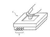
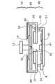
図1は、本発明に係る触覚インタフェース装置の一実施の形態を示した概略的な斜視図である。図2は、図1に示した触覚インタフェース装置の筐体上面を取り除いた状態の平面図であり、図3は、図2に示した触覚インタフェース装置の側面図である。
【0029】
本実施の形態における触覚インタフェース装置2は、図1から明らかなように外部装置と信号交換を行うための端子及び電源端子から構成される外部接続端子4が設けられており、外部装置に埋め込み可能な構造を有している。触覚インタフェース装置2は、ユーザインタフェース部10と駆動部20と制御部40とに大別できる。ユーザインタフェース部10は、操作者によって操作される操作部12を有している。操作部12を支持する基台14の中心部分には、発光部16が取り付けられている。なお、図2には、発光部16を便宜的に省略している。
【0030】
駆動部20は、操作部12を操作する操作者に反力を与えるために操作部12に対して電磁気により駆動力を与える。このため、駆動部20は、駆動部20を格納するケース21の中に、極性が交互になるように配設された磁石22,23,24,25を有している。磁石22〜25は、装置2の厚さ方向に分極されており、隣接した磁石間で磁界が発生するようにしている。磁石21〜25の上方の空間には、各磁石21〜25の間にそれぞれが配設されるようにコイル26,27,28,29と、各コイル26〜29を取り付けるフレーム30とが設けられている。フレミングの左手の法則に従い、磁界中をX軸方向に並設したコイル26,28に対して電流を所定方向に流すことによって可動状態にあるフレーム30をY軸方向に沿って駆動する。同様にY軸方向に並設したコイル27,29に対して電流を所定方向に流すことによってフレーム30をX軸方向に沿って駆動する。従って、上記コイルの組のいずれか一方のみに電流を流せば一次元方向に、双方に電流を流せば各一次元方向のベクトル和により表される二次元方向に、フレーム30を駆動することができる。このように、駆動部20は、ケース21の中においてフレーム30を可動可能にした構造を有している。後述する制御部40は、信号線31を介してコイル26〜29へ電流を流すことによって駆動部20の駆動制御に行うことでフレーム30を変位させ、フレーム30に取り付けられている操作部12は、フレーム30の変位に連動して変位することになるが、駆動部20は、操作者に反力を与えるために制御部40における駆動制御のもと、操作部12に対して電磁気により駆動力を与えることになる。駆動部20は、例えば上記特許文献4に記載された2次元アクチュエータにより実現することができる。
【0031】
ケース21の中心部分には、発光部16が発した光を光センサ41が受光できるように開口部32が設けられている。光センサ41は、光検出方向により操作部12の移動量を検出するので、開口部32は、操作部12の可動範囲において光の通過を阻止しないような大きさとする必要がある。また、光センサ41は、光検出方向だけでなく光の照射位置や光量から検出する方法を用いるようにしてもよい。
【0032】
制御部40は、制御手段として駆動手段の駆動制御を行うための制御回路が形成された制御基板42と、制御基板42上に配設された前述の光センサ41とを有している。光センサ41は、前述したように発光部16が発した光を検出することによって操作部12の可動範囲内における位置を検出する。本実施の形態における検出手段は、この光センサ41と、制御基板42上に形成され、操作者が操作部12に対して行っている操作状況を検出する検出回路(図示せず)とを有している。なお、操作部12の可動範囲は、光センサ41による光の検出範囲と同義であるが、実際には筐体の表面33の開口領域の大きさにより決定される。
【0033】
なお、操作者が操作部12に対して行っている操作状況というのは、操作部12を上下方向及び/又は左右方向に動かそうとしている行為や操作部12を現在位置に留めておこうとする行為、またその行為の強さ(操作部12を早くあるいはゆっくり移動させる)など操作者が操作部12をどのように操作している、操作しようとしているかを知るために必要な情報のことをいう。本実施の形態における検出回路は、この操作者による行為(操作状況)を検出するために操作部12にかかる速度、加速度及びその力の加わる方向等を検出する。制御基板42には、更に検出手段が検出した信号を外部装置へ出力する外部接続端子4が接続されている。
【0034】
本実施の形態における触覚インタフェース装置2は、上記のように構成されており、一般に外部接続端子4を電気・電子機器、情報機器等の外部装置に接続し外部装置の筐体内に組み込まれて使用されると考えられる。このため、ケース21を含む触覚インタフェース装置2の筐体は、ケイ素鋼板等の磁気シールド材で形成することが好適である。また、触覚インタフェース装置2の筐体の表面33は、搭載する外部装置を形成する筐体や画像表示画面等と共用することができる。
【0035】
そして、詳細は後述するが、本実施の形態における触覚インタフェース装置2は、この1つの装置2でジョイスティックやトグルスイッチ、スライドレバー、マウス(のクリックボタン)等種々のインタフェース装置と同等の操作感を操作者に与えることができる。触覚インタフェース装置2をどの種類のインタフェース装置として機能させるか、換言すると操作部12をどの種類のインタフェース装置の操作部のように振舞わせるかは、制御部30における駆動部20の駆動制御により決定される。
【0036】
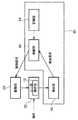
図4は、本実施の形態における触覚インタフェース装置2の機能ブロック構成図である。図4には、図3に対応させて、ユーザインタフェース(UI)操作部10、駆動部20及び制御部40が示されている。このうち、制御部40には、前述した光センサ41と検出回路によって実現される機能を有する検出部52と、制御回路によって実現される機能を有する制御部56とが含まれている。検出部52は、操作者による操作状況や操作部50の位置を検出して、その操作状況や位置を知らせるために制御部56へ検出信号を出力する。駆動部20は、操作者に反力を与えるために操作部12に対して駆動力を与える。制御部56は、検出部52からの出力信号に応じて駆動部20の駆動制御を行う。
【0037】
駆動部20は、上記のように制御部56による制御に従い操作部12を介して操作者に反力を与えることで、操作部12が振舞うべきインタフェース装置が通常操作者に与えている操作感を作り出すわけであるが、制御部56は、予め設定されているインタフェース定義情報に基づき駆動部20の駆動制御を行っている。このインタフェース定義情報の詳細については後述することにして、ここでは、まず、触覚インタフェース装置2がジョイスティックとして動作する場合を例にして触覚インタフェース装置2における基本的な動作について図5を用いて説明する。
【0038】
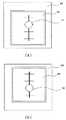
図5(a)には、図2と同様に触覚インタフェース装置2を上方から見たときの平面図であり、触覚インタフェース装置2の表面33と操作部12の頂部が示されている。図5(b)は、操作部12の位置と、駆動部20が操作部12に対して与える駆動力との関係を示した図である。インタフェース定義情報には、図5(b)に示した駆動力を駆動部20に発揮させるように駆動部20を制御することになる。
【0039】
例えば、操作者がX軸に沿ってそのプラス方向に操作部12を操作したとする。検出部52は、その操作に伴い検出した操作状況と操作部12の位置を検出信号として制御部56へ出力する。制御部56は、検出部52からの検出信号により操作部12がX軸に沿ってそのプラス方向に移動されたことを認識すると、図5(b)に模式的に示されているような予め設定されているインタフェース定義情報に基づいて駆動部20の駆動制御を行うことになる。すなわち、図5(b)のX軸についてのグラフを参照すると、X軸プラス方向では負の方向に駆動力を与えることがわかるので、駆動部20に対してそのような制御信号を出力する。駆動部20は、その制御信号に基づき操作部12に対してX軸の負の方向、すなわち矢印6aで示したX軸に沿ってそのマイナス方向に駆動力をかける。これにより、操作者には、操作部12の操作方向とは反対方向の反力が与えられる。なお、図5(b)に示した例では、操作部12の中心から離れるにつれて与えられる駆動力は増加することになる。
【0040】
また、例えば、操作者がX軸とY軸の共にマイナス方向に操作部12を操作したとする。検出部52は、その操作に伴い検出した操作状況と操作部12の位置を検出信号として制御部56へ出力する。制御部56は、検出部52からの検出信号により操作部12がX軸とY軸との間のマイナス方向に移動されたことを認識すると、図5(b)に模式的に示されているような予め設定されているインタフェース定義情報に基づいて駆動部20の駆動制御を行うことになる。すなわち、図5(b)のX軸についてのグラフを参照すると、X軸マイナス方向では正の方向に駆動力を与えることがわかる。また、図5(b)のY軸についてのグラフを参照すると、Y軸マイナス方向では正の方向に駆動力を与えることがわかる。すなわち、制御部56は、駆動部20に制御信号を出力することによって各軸にかけるべき駆動力を知らせる。駆動部20は、その制御信号に基づき操作部12に対してX軸の正の方向かつY軸の正の方向、すなわち矢印6bで示した方向に駆動力をかける。これにより、操作者には、操作部12の操作方向とは反対方向の反力が与えられる。
【0041】
すなわち、本実施の形態によれば、図5(b)に模式的に示したインタフェース定義情報に基づき、検出部52からの検出信号に応じた方向及び強さの駆動力を駆動部20にかけさせるように駆動部20の駆動制御を行うことにより、ジョイスティックから得られるべき操作感を操作者に与えることができる。
【0042】
ここで、インタフェース定義情報について詳述する。
【0043】
前述したように、制御部56は、入力された検出信号に応じてインタフェース定義情報に基づき駆動部20の駆動制御を行う。ジョイスティック装置の操作部(ジョイスティック)は、2次元方向に動くので、図5(b)に例示したように2次元方向への動作について定義すればよいわけであるが、図5(b)に示したグラフの線の傾きを変えれば、操作者に与える反力の強さを変えることができる。例えば、グラフ線の傾きを大きくすれば、反力(抵抗感)を強くすることができ、これにより抵抗感あるいは向心力の大きなジョイスティック装置を操作しているという操作感を提供することができる。一方、グラフ線の傾きを小さくすれば、反力を弱くすることができ、これにより抵抗感あるいは向心力の小さいジョイスティック装置を操作しているという操作感を提供することができる。このように、インタフェース定義情報には、図5(b)で模式的に表現できるようなインタフェース装置(ここではジョイスティック装置)として動作する際の仕様情報が定義されている。
【0044】
なお、詳細については改めて後述するが、図5(b)で模式的に表現できるインタフェース定義情報によって駆動部20の駆動力、つまり、触覚インタフェース装置2としての動作は定義される。つまり、駆動力を示すグラフ線の形状によって触覚インタフェース装置2としての動作は定義されるのだから、インタフェース定義情報にインタフェース装置の種類を必ずしも設定しておく必要はない。ここでは、図5に示したジョイスティック装置として動作する際のインタフェース定義情報しか定義していないので、インタフェース定義情報と仕様情報とは同義である。
【0045】
上記説明では、触覚インタフェース装置2における基本動作を説明するために、制御部56の内部にインタフェース定義情報を予め設定しておき、図5(b)に基づく一意的な反力を与えるような装置として説明した。従って、例えば、図6に示したように、インタフェース定義情報を記憶する記憶部58を更に設けておき、記憶部58の内容を書き換えることにより、所望の操作感を与えることのできるジョイスティックを提供することができる。
【0046】
ここで、制御部56における動作について更に詳述すると、制御部56は、検出部52からの検出信号により認識できる操作部12の存在位置Xと目標制御位置Xtとの差分から駆動部20での出力FをPID制御によって決定する。これらの関係式は次のようになる。
【0047】
F=Kp×(X-Xt)+Kd/dt×[(X-Xt)−(X0-Xt0)]+Ki×∫(X-Xt)dt
【0048】
ここで、X0は1サイクル前の検出位置、Xt0は1サイクル前の目標位置である。触覚インタフェース装置2の場合、外乱には操作者の操作が含まれるのでPID制御のKiは0としてPD制御で用いるとよい。また、制御サイクルは操作部12にゴツゴツ感を発生させないよう少なくとも数百〜1KHzの周波数を用いる。これらの制御によって、Kpによる操作部12の復元力(反力)は、図5(b)のようになり、操作部12は、図5(a)に示されるように目標位置(本実施の形態の場合は中央)に復元力を持ったジョイスティックとして機能させることができる。そして、この場合は、前述したグラフ線の傾きというのは、係数Kpの値によって決定されることになる。なお、グラフ線の形状により模式的に表される仕様情報というのは、グラフ線を表す計算式とその計算式に含まれる各係数の値の組合せによって決定する。
【0049】
本実施の形態では、各係数が一定の上記計算式を仕様情報として記憶部58に予め記憶し、必要に応じて記憶した仕様情報を変更するように説明したが、各係数を外部から入力指定できるようにし、制御部56が指定された係数を反映させた計算式により出力Fを決定するようにしてもよい。この場合は、係数が可変なままの計算式が仕様情報となり、係数の値を変更することによって一つのインタフェース装置を操作している間に操作部12に対する同じ操作に対して異なる操作感を与えることができる。
【0050】
本実施の形態によれば、ジョイスティックやスイッチなどの入力装置として動作する際に、操作者に与える操作感を弾性部材などの素材によって実現するのではなく、電磁気的に動作する2次元アクチュエータを用いて実現しているので、インタフェース装置として与える操作感の劣化を防止することができる。また、動作方向も回転方向以外の略2次元平面内の方向にも反力を与えることができる。
【0051】
実施の形態2.
図7は、本実施の形態における触覚インタフェース装置の機能ブロック構成図である。なお、実施の形態1と同じ構成要素には同じ符号を付ける。以降の実施の形態においても同様とする。本実施の形態においては、図6に示した装置構成に、検出部52からの出力信号により操作者による操作状況を判断する操作判断部60を制御部56に設けたことを特徴とする。本実施の形態においては、触覚インタフェース装置2がトグルスイッチとして動作する場合について図8を用いて説明する。
【0052】
図8は、実施の形態1の図5に相当する図であり、図の見方は図5と基本的には同じなので説明を省略する。
【0053】
図8では、矢印6a〜6dで示された反力の向きの中心がスイッチONの状態、矢印6e〜6hで示された反力の向きの中心がスイッチOFFの状態にあると設定している。図8(a)では、操作部12の滞留点として点7a,7bでそれぞれ示すことにする。そして、矢印6b,6i,6fと矢印6d,6j,6hとにより表された反力が操作部12に与えられることから、操作部12がY軸上からずれないように誘導されることがわかる。このように、制御部56は、インタフェース定義情報に基づき操作部12が略2次元平面内の一定の略直線上に拘束されるように駆動部20の駆動制御を行うことによりトグルスイッチを実現できる。反力についてより詳細に説明すると、矢印6b,6i,6fと矢印6d,6j,6hで示される反力は、操作部12を略直線上に拘束するための反力であり、このうち、矢印6b,6d,6f,6hは、操作部12を各滞留点7a,7bに滞留させるための反力でもある。また、矢印6a,6c,6e,6gで示される反力は、操作部12を各滞留点7a,7bに滞留させるための反力でもあり、そのうち、矢印6c,6eは、更に操作者の意思によって操作部12を隣接した滞留点へ移動させるための誘導力でもある。
【0054】
なお、図8(a)には、操作部12を略直線上に拘束するために各方向に矢印6b,6i,6fと矢印6d,6j,6hを示したが、直線上の全ての位置においてY軸上に沿って移動するように反力を与えていることは図8(b)から明らかである。
【0055】
例えば、操作者がスイッチをONにしたいために操作部12をY軸のプラス方向に操作したとする。検出部52は、その操作に伴い検出した操作状況と操作部12の位置を検出信号として制御部56へ出力する。制御部56は、検出部52からの検出信号により操作部12がY軸のプラス領域にある場合には点7aの位置に操作部12を拘束するように制御する。すなわち、図8(b)のY軸についてのグラフを参照すると、Y軸プラス方向では中央に近いところでは極めて強い駆動力をプラス方向に与えていることがわかる。すなわち、操作部12がニュートラルな中心位置からY軸のプラス方向に操作者によって操作されると、操作部12を更にプラス方向へ積極的に誘導する。これにより、操作部12の動きをスムーズにすることができる。そして、ある距離移動すると、駆動力は低下し、駆動力を示すグラフ線はいずれY軸と交差することになる。この交差する点7aは、図8(a)における滞留点7aに相当する。つまり、滞留点7aでは、駆動力がゼロということであり、Y軸方向に関しては何ら反力を与えないということであり、これにより、操作部12は、外力が加わらない限り(通常は操作者による操作力)、点7aの位置に滞留することになる。よって、スイッチはONに保たれることになる。一方、ニュートラルな位置からスイッチをOFFにするときは、上記と動作は全く逆となるので、説明を省略する。
【0056】
スイッチの動作を誤動作やジッタリングのないより確実なものとするために、インタフェース定義情報をON/OFFそれぞれの状態に応じて用意し、ヒステリシス動作をさせることもできる。図9は操作部12がスイッチONの状態にあるときの、図10は操作部12がスイッチOFFの状態にあるときの図8に相当する図である。本実施の形態においては、図8で示されるインタフェース定義情報の代わりに図9及び図10で示されるインタフェース定義情報を記憶部58に記憶させ、状態の変化に応じて切り替えて用いている。つまり、触覚インタフェース装置2をトグルスイッチとして動作させる際の複数の仕様情報がインタフェース定義情報に定義されていることになる。前述したように、本実施の形態においては、操作判断部60を設けている。操作判断部60は、検出部52からの検出信号、この場合は光センサ41により検出された位置を示す検出信号に基づき操作部12がニュートラルな位置にいるときと判断したとき、制御部56は、参照する仕様情報ONのときには図9の仕様情報に基づいてマイナス方向に、OFFのときには図10の仕様情報に基づいてプラス方向に、同じトグルスイッチに対して異なる駆動制御を行うようになる。
【0057】
本実施の形態によれば、同じインタフェース装置に対して複数の仕様情報を設定し、操作部12の操作状況又は存在位置(本実施の形態では操作部12の位置)に応じて使用する仕様情報を切り替えることができるので、本来のインタフェース装置により近い、あるいは本来のインタフェース装置より良好な操作感を操作者に与えることができる。
【0058】
実施の形態3.
上記実施の形態2においては、ONとOFFの2カ所で滞留するトグルスイッチとして動作する場合について説明した。この滞留する箇所、つまり滞留点を略直線上に増やして多段階とすることで多段階選択スイッチの一形態であるスライドスイッチを実現することができる。なお、本実施の形態の機能ブロック構成は、図6又は図7と同じになる。
【0059】
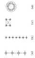
図11は、実施の形態3における触覚インタフェース装置をスライドスイッチとして動作させる際に操作部の滞留点7a〜7dを示した図である。可動範囲内において操作部に与えられる反力は、矢印6a〜6cに示したように図8乃至図10の各(a)に示した滞留点7a,7bを略直線上に更に連ねることによって表すことができる。また、図11では、操作部を省略している。
【0060】
図11には、操作部12を4点に滞留させるスライドスイッチが示されている。例えば、風量のスイッチであれば、各滞留点7a〜7dは、「切」、「弱」、「中」、「強」の位置に相当することになり、各滞留点間を移動する際には反力が与えられている。停留させる点をさらに多くとりほぼ連続的に移動可能な状態にする、あるいはY軸方向には駆動力が発生しないようにすることによってスライドボリュームのような動作をも実現することができる。
【0061】
ところで、ジョイスティックでは問題ないが、本実施の形態において例示した偶数個の滞留点のスライドスイッチ、また前述したトグルスイッチにも実際には当てはまるが、操作部12の可動範囲における中心点に滞留点が存在しない場合、操作部12を初期状態としていずれかの滞留点に位置決めしておくようにするように動作制御することが現実的である。従って、例えばスライドスイッチとしての動作を開始した場合、制御部56は、検出部52からの信号により操作部12の現在位置は特定できるので、インタフェース定義情報に基づき操作部12を予め決められている初期位置まで移動させ滞留させるように駆動部20を制御する。上記トグルスイッチの例だと、OFFの位置を初期位置とし、上記スライドスイッチの例だと、「切」の位置を初期位置とすることが好適であると考えられる。もちろん、これに限定されるものではなく、例えば、前回トグルスイッチとして振舞ったときの終了状態を記憶しておき、それを次回振舞い時の初期状態とするようにしてもよい。
【0062】
実施の形態4.
上記実施の形態3においては、多段階選択スイッチの一形態としてスライドスイッチを例示したが、本実施の形態においては、ジョグダイヤルを例示する。なお、本実施の形態の機能ブロック構成は、図7と同じになる。
【0063】
図12は、実施の形態4における触覚インタフェース装置をジョグダイヤルとして動作させる際に操作部の滞留点7a,7b,7c,・・・を示した図である。可動範囲内において操作部に与えられる反力は、矢印6a,6b,6c,・・・に示したように図8乃至図10の各(a)を略円周上に連ねることによって表すことができる。なお、図12では、操作部を省略している。
【0064】
更に、本実施の形態における制御部56は、操作部が略2次元平面内の一定の略円周上に拘束されるように駆動部20の駆動制御を行うことを特徴としている。すなわち、滞留点7aに対応させて示した反力6m,6nが操作部を略円周上に拘束するための反力に相当する。なお、本実施の形態におけるジョグダイヤルは、実施の形態4において示したスライドスイッチを丸めて円周上に配置し、そして、円形状とすることで形成できる。終端がない点で異なる以外は基本動作は同じなので、詳細な動作の説明は省略する。
【0065】
このジョグダイヤルは、ビデオデッキのコマ送り再生やオーディオ装置の回転式ボリューム等に採用されているが、本実施の形態によれば、触覚インタフェース装置をジョグダイヤルとして動作させることができる。
【0066】
なお、本実施の形態では、1周を12分割して12個の滞留点を形成した例を示したが、この滞留点の数はこれに限られたものではない。例えば、滞留点の数を多くしていくと、最終的には操作部がスムーズに動き、各滞留点への滞留感を感じないような触覚を操作者に与えることができる。一方、滞留点の数を少なくするとゴツゴツ感のあるジョグダイヤルを提供することができる。4点ほどまで少なくすると、スライドスイッチと同様の機能を持つ風量用のロータリースイッチとして操作させることも可能である。
【0067】
実施の形態5.
図13は、本実施の形態における触覚インタフェース装置の機能ブロック構成図である。本実施の形態における触覚インタフェース装置は、実施の形態2(図7)において示した構成に、インタフェース選択部62を更に追加した構成を有している。そして、制御部56は、外部装置と信号の送受信を行う。
【0068】
上記各実施の形態においては、本発明に係る触覚インタフェース装置をジョイスティック、トグルスイッチ等のインタフェース装置に適用した場合を例にして説明した。本実施の形態では、複数のインタフェース装置として動作させることを可能にしたことを特徴としている。このために、本実施の形態においては、記憶部58に複数のインタフェース装置に対するインタフェース定義情報を記憶しておき、制御部56は、駆動部20の駆動制御に用いるインタフェース定義情報を、ユーザにより選択されたインタフェース装置に対応するインタフェース定義情報に切り替えるようにしたことを特徴としている。インタフェース選択部62は、操作部12が振舞うインタフェース装置を選択するための手段である。
【0069】
ここでは、本実施の形態における触覚インタフェース装置を自動車に適用した場合を例にして説明する。図13は、本実施の形態における触覚インタフェース装置が取り付けられた自動車のハンドルの概略図である。図13には、ハンドル8に取り付けられた触覚インタフェース装置の操作部12と、インタフェース選択部62に相当するUP/DOWNボタン62a,62bが示されている。
【0070】
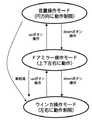
図14は、本実施の形態において切り替えられるインタフェース装置の遷移を示した概念図であり、この図から明らかなように、触覚インタフェース装置は、音量操作、ドアミラーの角度調整操作及びウィンカー指示操作のために用いられる。音量操作にはジョグダイヤルを、ドアミラー調整操作には上下左右に移動可能なジョイスティックを、ウィンカー操作にはスライドスイッチを利用することが好適であり、そのために各インタフェース装置として動作させるためのインタフェース定義情報を記憶部58に記憶させておく。
【0071】
以下、本実施の形態における動作について説明する。
【0072】
車両のスイッチONに伴い、外部装置、この場合は車載制御処理装置から始動信号を受信することで触覚インタフェース装置は作動を開始する。始動時のモードは何でもよく、予め設定したモードでもよいし、例えば、車両のスイッチOFF時の状態を保持しておき、次回のスイッチON時の初期モードとするようにしてもよい。ここで、ドアミラーの調整をしたければ、操作者は、必要に応じてUP/DOWNボタン62a,62bを操作し、ドアミラー操作モードに設定する。なお、現在どのモードが選択されているかは、制御部56が選択モード信号を車載制御処理装置へ出力し、車両のディスプレイに表示させるようにすればよい。
【0073】
触覚インタフェース装置は、ドアミラー操作モードのときには、ジョイスティックとして動作する。これにより、操作者は、操作部を上下左右に動かすことでドアミラーの角度調整を行うことができる。なお、左右のドアミラーの選択には左右方向に動作するトグルスイッチが有効であるが、ジョイスティックとトグルスイッチとの切替えは、図14にドアミラーの選択モードを図14に組み入れるなどのロジックにより対応できる。
【0074】
そして、UP/DOWNボタン62a,62bの操作により音量操作モードが選択されると、制御部56は、その選択に応じてインタフェース定義情報をジョイスティック用からジョグダイヤル用に切り替えて駆動部20の駆動制御を開始する。これにより、触覚インタフェース装置は、音量操作モードが選択されたときにはジョグダイヤルとして動作することができる。そして、UP/DOWNボタン62a,62bの操作によりウィンカー操作モードが選択されると、制御部56は、その選択に応じてインタフェース定義情報をジョグダイヤル用からスライドスイッチ用に切り替えて駆動部20の駆動制御を開始する。これにより、触覚インタフェース装置は、音量操作モードが選択されたときにはジョグダイヤルとして動作することができる。
【0075】
ウィンカー操作モードに適用するスライドスイッチは、中央とその左右方向に滞留点を有し、左右方向のみに動作可能な3段階のスライドスイッチとして動作させることが好適である。従って、操作部をこのように動作させる仕様情報がインタフェース定義情報に定義される。
【0076】
以上のように、本実施の形態では、複数のインタフェース装置を一つの操作部により実現することができるので、インタフェース装置の取付スペースを削減することができる。ここに例示したように、多機能化した車両に取り付ける際には特に有効である。但し、より良好に車両の走行に適合させるには、モード切替に何らかの工夫が必要になる。例えば、車両走行にはウィンカーは必要なので、図14に示したように車両の前進を感知したり、あるいは音量操作やドアミラー操作が一定時間されなければ、ウィンカー操作モードに自動遷移させるようにする。また、現在の車両では、ウィンカーを表示しその方向へハンドルを回し、そしてハンドルが元に戻るときにはウィンカーの表示はハンドルの動きに追従して取り消される。従って、同様の動作制御が実現できるようにしなければならない。このためには、次のようにすればよい。
【0077】
ウィンカー用のスライドスイッチの仕様情報は、前述したように初期の状態として左右方向に並ぶ3点の滞留点を有している。つまり、そのように操作部を動作させる仕様情報が定義されており、それを使用している。そして、制御部56は、車載制御処理装置若しくは操舵角センサ等が発するハンドルの操舵角あるいは回転角等の信号を常時入力しており、ハンドルが回された後ある程度戻ったときに操作部を滞留させていた滞留点を削除した仕様情報に切り替える。なお、仕様情報の切替については、実施の形態2において説明した。なお、仕様情報を切り替えずにジョイスティックのインタフェース定義情報に切り替えるようにしても実現可能である。そして、ハンドル操作終了時には、左右方向に並ぶ3点の滞留点を有する3段階のスライドスイッチの仕様情報に切り替える。このように、滞留していた位置に滞留点のない仕様情報に切り替えることで操作部をニュートラルな中央位置に自動的に戻すことができる。
【0078】
上記実施の形態では、一つのインタフェース定義情報のみを記憶部58に記憶させ、その中に1乃至複数の仕様情報を定義し、操作部の位置によって仕様情報を適宜切り替える触覚インタフェース装置を説明した。これにより、例えば、スライドスイッチであれば、同じスライドスイッチの操作においても操作部の位置や移動方向によって仕様情報を切り替えることで操作者に与える操作感を変更することができた。
【0079】
本実施の形態においては、複数のインタフェース定義情報を記憶部58に記憶させ、その中に1乃至複数の仕様情報が定義し、操作部の位置や外部装置から送られてくる信号に応じて仕様情報又はインタフェース定義情報を適宜切り替える触覚インタフェース装置を説明した。これにより、一つの触覚インタフェース装置によって異種のインタフェース装置の操作を提供することができる。また、同種であっても3段階や4段階など異なる動作のスライドスイッチを提供することができる。なお、同種のインタフェース装置であっても動作自体が異なれば、異なるインタフェース装置として扱い、これにより、インタフェース定義情報を別個に生成する。
【0080】
また、以上の説明から明らかなように、本実施の形態における触覚インタフェース装置をいずれかのインタフェース装置として機能させるには、仕様情報として定義する内容(図8(b)等で表現されるグラフ線の形状)によって決まってくる。換言すると、仕様情報として定義する内容いかんでは、所望するインタフェース装置を作成できるということである。例えば、上下方向と左右方向にそれぞれ動作するスライドスイッチを連結してT字形状やL字形状のスライドスイッチ、あるいはスライドスイッチの終端部はジョイスティックになっているようなインタフェース装置など新たなインタフェース装置の操作感を提供することができる。このように、本実施の形態によれば、複数のインタフェース装置を一つの操作部で実現できるだけでなく、仮想的な新たなインタフェース装置を作成することも可能である。
【0081】
なお、実施の形態1においては、一つのインタフェース定義情報のみ生成され、その中に一つの仕様情報のみが定義されていたので、各情報の識別情報は不要であった。また、実施の形態2では、一つのインタフェース定義情報のみ生成され、その中に複数の仕様情報のみが定義されていたので、仕様情報に識別情報が必要でもインタフェース定義情報には識別情報が不要であった。本実施の形態においては、複数のインタフェース定義情報が生成されているので、モード切替の際に各インタフェース定義情報を識別できるように、インタフェース定義情報にはその情報の識別情報を含ませる必要がある。
【0082】
また、本実施の形態では、操作部から離れた位置にUP/DOWNボタン62a,62bを選択スイッチとして別途設けたが、操作部に選択スイッチ機能を付加して一体に形成するようにしてもよい。例えば、操作部の頂部に圧力センサを取り付け、制御部56は、圧力センサが一定以上の押圧力を検出すると、それを操作者によるモード切替操作と認識してモードを切り替える。なお、この場合は、遷移する方向は一方向のみなので、モードの移行遷移はサイクリックとなる。
【0083】
上記実施の形態では、触覚インタフェース装置を2次元リニアモータで実現することができるが、本実施の形態においては、3次元方向の操作を検出する必要がある。そのため、圧力センサなどの検出手段が必要となるが、これにより、外部装置に取り付けるスイッチの数を更に削減することができる。また、圧力センサに押圧力の有無を検出できるようにすれば、タッチセンサとしての動作を実現することができる。
【0084】
実施の形態6.
上記実施の形態5では、触覚インタフェース装置を自動車のハンドルに適用した例を示した。本実施の形態では、外部装置が情報処理装置の場合を例にして説明する。
【0085】
図16(a)は、本実施の形態における触覚インタフェース装置を示した概略的な側面図であり、図16(b)は、図16(a)において情報処理装置に何も表示されていない状態の平面図である。本実施の形態における触覚インタフェース装置2は、情報処理装置80と一体に形成されている。触覚インタフェース装置2は、外部接続端子を情報処理装置80に接続しており、制御部56は、検出信号を外部装置へ出力できる。また、操作部12は、ガラス板34、アーム35を介して情報処理装置80に対して相対的に可動できる状態に取り付けられている。情報処理装置80の画像表示部82は、上向きに設置されており、その画像表示部82の上側に触覚インタフェース装置2の操作部12が配設される。そして、画像表示部82による表示内容を遮らないように情報処理装置80の下側に制御部と駆動部20の一部を含む触覚インタフェース装置2の本体が配設される。操作部12は、画像表示部82による表示内容が見れるように透明である板材の上、本実施の形態ではガラス板34の上に載置される。ガラス板34は、装置2の本体から延出した少なくとも1組のアーム35によって支持される。本実施の形態では、操作部12に対して加わる操作力を、操作部12、ガラス板34、アーム35を介して装置本体内の検出手段へ、同時に触覚インタフェース装置2から発生される駆動力を操作部12に伝える構造になっている。
【0086】
本実施の形態における動作について図17を用いて説明する。図17では、情報処理装置80がスライドスイッチを表示するときの例を示している。操作部12は、装置2において中央に位置しているとすると、情報処理装置80は、制御部40から送られてきた検出信号によりその位置を認識できるので、操作部12の現在位置に合わせてスライドスイッチを表示する。操作部12の初期位置が図17(a)に示したように上から2番目のレベルだとすると、情報処理装置80は、表示したスライドスイッチの2番目のレベル上に操作部12がくるように操作部12を相対的に移動させる。一方、制御部40は、情報処理装置80から送られてきた信号に基づきスライドスイッチが表示されたことを認識すると、そのスライドスイッチに対応するインタフェース定義情報に基づき駆動部20の駆動制御を行うようにする。
【0087】
そして、操作者がスイッチを下から3番目のレベルに移動させようと操作部12を操作すると、制御部40は、上記実施の形態で説明したように操作者に操作感を与えると共に検出部が検出した検出信号を外部接続端子4を介して情報処理装置80へ出力する。この際、制御部40は、操作者に操作部を押し下げているような操作感を与える。制御部40から送られてきた検出信号を入力した情報処理装置80は、その検出信号に応じて表示したスライドスイッチの3番目のレベル上に操作部12がくるように操作部12を相対的に移動させる。この状態を図17(b)に示す。図17では、情報処理装置80が移動したようにみえるが、実際には上記の通り操作部12が相対的に移動する。
【0088】
また、図18では、情報処理装置80がジョグダイヤルを表示するときの例を示している。情報処理装置80は、操作部12は、装置2において中央に位置しているとすると、情報処理装置80は、制御部40から送られてきた検出信号によりその位置を認識できるので、操作部12の現在位置に合わせてジョグダイヤルを表示する。スライドスイッチのときと同様に、操作部12が初期位置にくるように操作部12を相対的に移動させる。一方、制御部40は、情報処理装置80から送られてきた信号に基づきジョグダイヤルが表示されたことを認識すると、そのジョグダイヤルに対応するインタフェース定義情報に基づき駆動部20の駆動制御を行うようにする。
【0089】
そして、操作者が例えば図18(a)に示した位置から180度回転させようと操作部12を操作すると、制御部40は、検出部が検出した検出信号を外部接続端子4を介して情報処理装置80へ出力する。この際、制御部40は、操作者に操作部を操作方向に回しているような操作感を与える。制御部40から送られてきた検出信号を入力した情報処理装置80は、その操作者による操作に応じて表示したジョグダイヤルがあたかも180度回転したように操作部12を相対的に移動させる。この状態を図18(b)に示す。図18では、情報処理装置80が移動したようにみえるが、実際には上記の通り操作部12が相対的に移動する。
【0090】
本実施の形態によれば、搭載された外部装置に対して検出信号を出力し、また、外部装置から表示内容に関する情報を受け取ることで、画像を表示する情報処理装置と連動して動作することができる。また、操作部を表示画面上に配設したことにより表示内容と操作部との一体感が生まれ、視覚的にもあたかもその場所にスイッチがあるかのように操作者にイメージさせることができる。
【0091】
実施の形態7.
上記実施の形態5では、触覚インタフェース装置を自動車のハンドルに適用した例を示した。本実施の形態では、外部装置がオーブンレンジの場合を例にして説明する。なお、本実施の形態における触覚インタフェース装置の機能ブロックは、図13と同じである。
【0092】
図19は、本実施の形態における触覚インタフェース装置を搭載したオーブンレンジの操作パネルを示した概略図である。オーブンレンジのように操作手順がフローになっている場合、各モードを階層構造で遷移させる必要がある。階層の移動は、図19に示した決定/取消ボタンによって行われるが、本実施の形態では、インタフェース選択部62が決定/取消ボタンに相当する。図19には、表示パネル86と、触覚インタフェース装置の操作部12とインタフェース選択部62による決定/取消ボタン62,62bが示されている。表示パネル86は、上記実施の形態6において説明した情報処理装置の画像表示部に相当し、情報処理装置及び触覚インタフェース装置の制御部と駆動部はオーブンレンジの筐体内に収納されている。
【0093】
図20は、本実施の形態における触覚インタフェース装置の操作モードの遷移を示した図である。以下に、本実施の形態における動作について説明する。
【0094】
初期状態において表示パネル86には、図19に示したように縦4段階のスライドスイッチによる加熱モードの選択画面が表示されている。操作者は、この表示内容に従い操作部12を操作して、所望の加熱モードを選択する。操作部の動作制御、表示パネル86への表示制御、情報処理装置と触覚インタフェース装置との連係動作については、実施の形態6と同様なので説明を省略する。ただ、表示画面と操作部とが一体でない本実施の形態においては、表示と操作は次のように連係動作する。例えば、スライドスイッチ上を動くスライドノブを下方に移動させたいとき、操作者は操作部12を下方に操作力を加えるので、情報処理装置は、制御部から送られてきた検出信号に従い表示されているスライドノブを下方に移動させる。
【0095】
ここで、例えば「レンジ強」にスライドノブが合わせられているときに決定ボタン62aが押下されると、図20に示したように加熱時間の設定モードに遷移するので、情報処理装置は、加熱時間の設定画面(例えばデジタル時計)を表示する。制御部は、情報処理装置から送られてきた信号に応じて操作部12をスライドスイッチからジョグダイヤルとしての操作感を与えるように駆動部を制御する。一般に、ジョグダイヤルを右に回せば設定時間が増え、左に回せば設定時間が減るので、本実施の形態においてもこの操作に準じる。更に、決定ボタン62aを押すことにより加熱がスタートし、加熱終了と共に再び初期状態に戻るようにする。
【0096】
本実施の形態によれば、オーブンレンジの操作パネルに組み込んだときに、スライドスイッチやジョグダイヤルなど実際のスイッチと同等の操作感を一つの操作部12のみで与えることができる。これにより、操作パネルの小型化を図ることができる。
【0097】
なお、本実施の形態では、決定ボタン62aを別途は移設したが、操作部12の上に搭載してもよい。そうすることによって、手の動作が少なくなり、より操作性を改善することができる。
【0098】
実施の形態8.
本実施の形態では、外部装置が複写機の場合を例にして説明する。なお、本実施の形態における触覚インタフェース装置の機能ブロックは、図13と同じである。
【0099】
近年の複写機は、数多くの機能が一つのタッチパネルへの操作によって実現されている。これらの機能の選択を本発明に係る触覚インタフェース装置によって操作することにより操作性を大きく向上させることができる。
【0100】
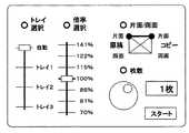
図21は、本実施の形態における触覚インタフェース装置を搭載した複写機の操作パネルを示した概略図である。図21に示された操作パネルによると、トレイ選択、倍率選択、片面又は両面印刷及びコピー枚数が設定できる。各モードは、インタフェース選択部62により実現される図示しない選択ボタンによって切り替えられる。あるいは、各モードの割り付けられている領域をマウス等でクリック選択する、あるいは画像表示部をタッチパネルとしてタッチ操作により選択するようにしてもよい。また、図21には、操作部12を図示していないが、本実施の形態においては、操作パネル近傍に設けたり、あるいはマウスに取り付ける。インタフェース選択部62と操作部12とを同じマウスに取り付ければ、操作性は更に向上する。
【0101】
図21において、トレイ選択や倍率の選択は、段階(滞留点)数が異なるものの同じ縦方向のスライドスイッチにより実現され、片面/両面印刷の選択は、横方向のスライドに縦方向のトグルスイッチを組み合わせて実現でき、枚数の設定は、ジョグダイヤルにより実現される。制御部56は、インタフェース選択部62により選択されたインタフェース装置に対応したインタフェース定義情報に基づき駆動部20を駆動制御することは、上記各実施の形態において説明したとおりである。図21に示した各インタフェース装置に対応したインタフェース定義情報において設定される滞留点を図22に示す。なお、スライドスイッチとジョグダイヤルに関しては、実施の形態2,3において詳述しているので、ここで、片面/両面印刷の選択について図23を用いて説明する。
【0102】
図23には、図21に示した片面/両面印刷を選択するためのインタフェース装置のみを抽出した。このうち、図23(a)では、片面原稿と片面コピーの各滞留点を実線で結んで示していることから、片面原稿を片面コピーすることを選択したことが把握できる。この状態においては、操作部12には片面原稿と片面コピーの間をスライド移動可能な拘束力が働いている。ここで、原稿側を両面原稿に変更したいときはこれらの拘束力に対抗して操作部12を矢印6aの向きに動作させると画面は、図23(b)のようになると同時に、操作部12には図23(c)に示したように両面原稿と片面コピーと間を結ぶ斜めの線上に矢印6c,6dの方向の拘束力が働くように変化する。コピー側を両面に変更する場合や、これらの逆の操作も方向が逆になること以外は同じなので、説明を省略する。制御部56は、このような仕様情報に基づき駆動部20を制御する。なお、その仕様情報は、片面/両面印刷のインタフェース装置に対応したインタフェース定義情報に含まれていることは言うまでもない。
【0103】
前述した図23(a)に対応する仕様情報と図23(b)に対応する仕様情報とは同じインタフェース定義情報に含まれている。本実施の形態によれば、複写機に操作パネルにも適用することができる。
【0104】
実施の形態9.
上記実施の形態7では、外部装置として情報を表示する機能を有する情報処理装置と組み合わせた場合を説明したが、本実施の形態では、音を出力する音出力装置が接続された、あるいは音を出力する機能を有する情報処理装置と組み合わせた場合について説明する。なお、本実施の形態における触覚インタフェース装置の機能ブロックは、図13と同じである。
【0105】
前述したように、操作部12の操作状況や位置を検出した信号は、情報処理装置に送られるが、情報処理装置は、この検出信号によって認識した操作部12の位置や移動の速度、加速度に応じてその状態を表現する音を出力する。例えば、操作部12の動きが遅いときには低音を、早いときには高音を発したり、移動させてはいけない位置にあるときには警告音を発したりする。
【0106】
また、同じ位置で同じ操作であっても操作回数をカウントしておき、その値によって音を変えたりすることもできる。例えば、ボールペンのノック音をペン先を出すときの音としまうときの音を変えたりすることができる。一方、情報処理装置は、この状態の信号を制御部56に送り、制御部56は、ノック音をペン先を出すときとしまうときとで使用する仕様情報を切り替えることで、ボールペンのペン先を出すときとしまうときの操作感を異ならせることができる。このように、制御部56は、外部装置からの信号に基づき操作部12の同じ位置での同じ操作でも異なる仕様情報を使用させることができる。
【0107】
以上のように、上記各実施の形態において、さまざまなインタフェース装置の操作感を与えるべき本実施の形態の動作について説明した。上記各実施の形態において、操作部12の操作方向のほとんどは2次元方向なので、実施の形態1に記載したように2次元アクチュエータにより実現することができるが、押圧力を検出する圧力センサと組み合わせることによりタッチパネルというインタフェース装置、更には押圧力に応じて仕様情報を切り替えるなど様々な操作感を与えることができ、また様々な種類のインタフェース装置を一つの操作部12によって提供することができる。そして、同じインタフェース装置においても仕様情報を切り替えることで粘性感、慣性感などさまざまな操作感を操作者に与えることができる。
【0108】
【発明の効果】
本発明によれば、操作者に与える反力を電気回路および磁気回路で置き換えているため、操作手段へ加わった圧力による機構部分の物理的な劣化を極力削減することができる。従って、長寿命で信頼性の高い触覚インタフェース装置を提供することができる。
【0109】
また、さまざまなインタフェース装置の操作感を一つの操作手段によって操作者に与えることができる。
【0110】
また、一つのインタフェース装置に対して駆動手段の駆動制御に用いる仕様情報を操作手段の操作状況や位置に応じて切り替えることでその操作状況や位置に適した操作感を与えることができる。
【0111】
また、外部接続端子から検出信号を外部装置へ出力できるようにしたので、操作状態や仕様情報の切替に応じて表示画像や音声出力を変化させることにより、よりユーザビリティの高い触覚インタフェース装置装置を提供することができる。
【図面の簡単な説明】
【図1】 本発明に係る触覚インタフェース装置の一実施の形態を示した概略的な斜視図である。
【図2】 図1に示した触覚インタフェース装置の筐体上面を取り除いた状態の平面図である。
【図3】 図2に示した触覚インタフェース装置の側面図である。
【図4】 実施の形態1における触覚インタフェース装置の機能ブロック構成図である。
【図5】 (a)は実施の形態1における触覚インタフェース装置をジョイスティックとして動作させる際に操作部に与える反力を示した図であり、(b)は触覚インタフェース装置をジョイスティックとして動作させるときの2次元方向の各軸と駆動力とを関係を示した図である。
【図6】 実施の形態1における他の触覚インタフェース装置の機能ブロック構成図である。
【図7】 実施の形態2における触覚インタフェース装置の機能ブロック構成図である。
【図8】 (a)は実施の形態2における触覚インタフェース装置をトグルスイッチとして動作させる際に操作部に与える反力を示した図であり、(b)は触覚インタフェース装置をトグルスイッチとして動作させるときの2次元方向の各軸と駆動力とを関係を示した図である。
【図9】 (a)は実施の形態2における触覚インタフェース装置の操作部がONの位置にあるときに操作部に与える反力を示した図であり、(b)は操作部がONの位置にあるときの2次元方向の各軸と駆動力とを関係を示した図である。
【図10】 (a)は実施の形態2における触覚インタフェース装置の操作部がOFFの位置にあるときに操作部に与える反力を示した図であり、(b)は操作部がOFFの位置にあるときの2次元方向の各軸と駆動力とを関係を示した図である。
【図11】 実施の形態3における触覚インタフェース装置をスライドスイッチとして動作させる際に操作部に与える反力と操作部の滞留点を示した図である。
【図12】 実施の形態4における触覚インタフェース装置をジョグダイヤルとして動作させる際に操作部に与える反力と操作部の滞留点を示した図である。
【図13】 実施の形態5における触覚インタフェース装置の機能ブロック構成図である。
【図14】 実施の形態5における触覚インタフェース装置を自動車のハンドルに配設したときの概略図である。
【図15】 実施の形態5において触覚インタフェース装置の操作モードの遷移を示した図である。
【図16】 (a)は、実施の形態6における触覚インタフェース装置を示した概略的な側面図であり、(b)は、(a)において情報処理装置に何も表示されていない状態の平面図である。
【図17】 実施の形態6において触覚インタフェース装置を搭載した情報処理装置が表示したスライドスイッチと操作部との位置関係を示す表示画面例を示した図である。
【図18】 実施の形態6において触覚インタフェース装置を搭載した情報処理装置が表示したジョグダイヤルと操作部との位置関係を示す表示画面例を示した図である。
【図19】 実施の形態7における触覚インタフェース装置を搭載したオーブンレンジの操作パネルを示した概略図である。
【図20】 実施の形態7において触覚インタフェース装置の操作モードの遷移を示した図である。
【図21】 実施の形態8における触覚インタフェース装置を搭載した複写機の操作パネルを示した概略図である。
【図22】 図21に示した各インタフェース装置における滞留点を示した概念図である。
【図23】 実施の形態8において片面/両面印刷のインタフェース装置の状態を示した概念図である。
【符号の説明】
2 触覚インタフェース装置、4 外部接続端子、10 ユーザインタフェース部、12 操作部、14 基台、16 発光部、20 駆動部、21 ケース、22,23,24,25 磁石、26,27,28,29 コイル、30 フレーム、31 信号線、32 開口部、33 表面、34 ガラス板、35 アーム、40,56 制御部、41 光センサ、42 制御基板、52 検出部、58 記憶部、60 操作判断部、62 インタフェース選択部、80 情報処理装置、82 画像表示部。[0001]
BACKGROUND OF THE INVENTION
The present invention relates to a tactile interface device, in particular, a device that can give various operation feelings obtained when operating the interface device such as resistance feeling or operation feelings of various interface devices such as a joystick and a toggle switch by one operation part. Regarding provision.
[0002]
[Prior art]
A wide variety of electrical and electronic devices are equipped with various interface devices such as toggle switches, jog dials, and slide switches to switch and instruct the functions provided by the devices. In addition, interface devices such as joysticks and trackballs that are common in information equipment are also used. These interface devices give the operator a sense of operation using the restoring force of an elastic material such as a spring or rubber, in order to facilitate the perception of proper switching of the functions and instructions of each interface device. Designed as such.
[0003]
However, in the method using such an elastic material, it is unavoidable in principle that the pressure applied by the operator to the operation portion is applied to the elastic member or its supporting portion. There was a problem that the intended reaction force could not be given.
[0004]
Also, in recent electrical and electronic devices, due to the sophistication and complexity of the functions provided by the devices, it is not possible to install all the functions on the operation panel. Has been done. For this reason, the operator may not always be given the optimal operational feeling for perceiving the switching of the function. In addition, there is a problem that the operability of the interface device is impaired in exchange for sophisticated and complicated functions, such as using an interface device having no tactile sensation such as a touch panel.
[0005]
In order to solve these problems, several inventions have been made so far. For example, a technique is disclosed in which a function can be selected by moving a rotary knob-type operation unit in the horizontal direction, and at the same time force feedback control is performed in the rotation direction of the knob to give the operator a feeling of operation according to the function. (See Patent Document 1). Also disclosed is a technology that makes it easy to understand the function selection state by changing (restricting) the degree of freedom of the operation unit that operates around the three axes x, y, and z according to the function selected by voice. (See Patent Document 2). Furthermore, in order to make the operation of the touch panel easy to understand, a technique is disclosed in which the touch panel itself is vibrated and a click feeling or the like is presented to the operator (see Patent Document 3).
[0006]
[Patent Document 1]
JP 2002-109558 A
[Patent Document 2]
JP-A-9-244866
[Patent Document 3]
JP-A-10-293644
[Patent Document 4]
JP 2000-330688 A
[0007]
[Problems to be solved by the invention]
However, in the
[0008]
In addition, in
[0009]
The present invention has been made to solve the above problems, and an object of the present invention is to provide a haptic interface device capable of preventing a change in operational feeling accompanying deterioration of a member that generates a reaction force. It is in.
[0010]
It is another object of the present invention to provide a tactile interface device capable of giving operational feelings associated with various operations such as rotational movement, horizontal movement, vertical movement, and pointing of a screen by a tactile sense at a single operation site.
[0011]
[Means for Solving the Problems]
In order to achieve the above object, a haptic interface device according to the present invention includes an operating means operated by an operator and a drive that applies a driving force to the operating means in order to provide a reaction force to the operator. Means, detecting means for detecting an operation status performed by the operator on the operating means or a position within the movable range of the operating means and outputting a signal; and when the operating means operates as one interface device. Storage means for storing interface definition information in which a plurality of specification information is defined, and control means for performing drive control of the drive means in accordance with an output signal from the detection means based on the interface definition information. The control means includesWhen the operation means operates as one interface device, among the plurality of defined specification information,The drive means is controlled by switching to specification information corresponding to the position of the operation means detected by the detection means.
[0012]
The interface definition information includesWhen the operating means is located in the middle of the stay points adjacent to each other,Specification information is defined in which the control means gives a reaction force to the operation means in different directions.
[0013]
AlsoThe control means controls the drive means to move the operating means to a predetermined initial position based on the interface definition information when starting drive control of the drive means.
[0014]
AlsoThe control means switches the interface definition information used for drive control of the drive means to interface definition information corresponding to the interface device selected by the interface selection means.
[0015]
Further, the operating range of the operating means is operated in a substantially two-dimensional plane.
[0016]
Further, the control means performs drive control of the drive means based on the interface definition information so that the operation means is constrained on a certain substantially straight line in a substantially two-dimensional plane.
[0017]
Alternatively, the control means performs drive control of the drive means based on the interface definition information so that the operation means is constrained on a certain approximate circumference in a substantially two-dimensional plane.
[0019]
Further, the interface selection means is formed integrally with the operation means.
[0020]
Further, the detection means detects a pressing force applied to the operation means.
[0021]
Furthermore, the control means switches the specification information corresponding to the pressing force detected by the detecting means or the displacement of the pressing force, and controls the driving of the driving means.
[0022]
In addition, an external connection terminal for outputting a signal detected by the detection means to an external device is provided.
[0023]
Furthermore, the control means selects a signal to be output from the external connection terminal according to the determination by the operation determination unit.
[0024]
Further, the control means outputs a signal from the detection means to an image display device which is an external device in order to display a behaving interface device.
[0025]
Furthermore, the operation means is arranged on the upper side of the screen of the image display device.
[0026]
Further, the control means outputs a signal from the detection means to a sound output device which is an external device in order that the behaving interface device outputs a sound that is originally generated in response to an operation by an operator. To.
[0027]
DETAILED DESCRIPTION OF THE INVENTION
Hereinafter, preferred embodiments of the present invention will be described with reference to the drawings.
[0028]
FIG. 1 is a schematic perspective view showing an embodiment of a haptic interface device according to the present invention. FIG. 2 is a plan view of the haptic interface device shown in FIG. 1 with the top surface of the housing removed, and FIG. 3 is a side view of the haptic interface device shown in FIG.
[0029]
The
[0030]
The
[0031]
An
[0032]
The
[0033]
Note that the operation situation that the operator is performing on the
[0034]
The
[0035]
As will be described in detail later, the
[0036]
FIG. 4 is a functional block configuration diagram of the
[0037]
The
[0038]
FIG. 5A is a plan view of the
[0039]
For example, it is assumed that the operator operates the
[0040]
Further, for example, it is assumed that the operator operates the
[0041]
That is, according to the present embodiment, based on the interface definition information schematically shown in FIG. 5B, the driving
[0042]
Here, the interface definition information will be described in detail.
[0043]
As described above, the
[0044]
Although details will be described later, the driving force of the driving
[0045]
In the above description, in order to explain the basic operation in the
[0046]
Here, the operation of the
[0047]
F = Kp x (X-Xt) + Kd / dt x [(X-Xt)-(X0-Xt0)] + Ki x ∫ (X-Xt) dt
[0048]
Here, X0 is a detection position one cycle before, and Xt0 is a target position one cycle before. In the case of the
[0049]
In the present embodiment, it has been described that the above calculation formulas with constant coefficients are stored in advance in the
[0050]
According to this embodiment, when operating as an input device such as a joystick or a switch, a feeling of operation given to the operator is not realized by a material such as an elastic member, but a two-dimensional actuator that operates electromagnetically is used. Therefore, it is possible to prevent deterioration of the operational feeling given as an interface device. In addition, the reaction force can be applied to the direction in the substantially two-dimensional plane other than the rotation direction.
[0051]
FIG. 7 is a functional block configuration diagram of the haptic interface device according to the present embodiment. In addition, the same code | symbol is attached | subjected to the same component as
[0052]
FIG. 8 is a diagram corresponding to FIG. 5 of the first embodiment, and the way of viewing the diagram is basically the same as FIG.
[0053]
In FIG. 8, the center of the reaction force direction indicated by the
[0054]
In FIG. 8A,
[0055]
For example, it is assumed that the operator operates the
[0056]
In order to make the operation of the switch more reliable with no malfunction or jittering, the interface definition information can be prepared in accordance with the ON / OFF state, and the hysteresis operation can be performed. FIG. 9 is a diagram corresponding to FIG. 8 when the
[0057]
According to the present embodiment, a plurality of specification information is set for the same interface device, and the specification information used in accordance with the operation status or the existing position of the operation unit 12 (the position of the
[0058]
In the second embodiment, the case where the switch operates as a toggle switch that stays at two locations of ON and OFF has been described. By increasing the number of staying points, that is, the staying points on a substantially straight line to be multistage, it is possible to realize a slide switch which is one form of a multistage selection switch. The functional block configuration of the present embodiment is the same as that in FIG. 6 or FIG.
[0059]
FIG. 11 is a diagram illustrating the stay points 7a to 7d of the operation unit when the tactile interface device according to the third embodiment is operated as a slide switch. The reaction force applied to the operating portion within the movable range is expressed by further connecting the
[0060]
FIG. 11 shows a slide switch that retains the
[0061]
By the way, although there is no problem with the joystick, although it is actually applied to the slide switch of the even number of staying points exemplified in the present embodiment and the toggle switch described above, the staying point is at the center point in the movable range of the
[0062]
In the third embodiment, the slide switch is illustrated as an example of the multistage selection switch. However, in the present embodiment, the jog dial is illustrated. The functional block configuration of the present embodiment is the same as that in FIG.
[0063]
FIG. 12 is a diagram illustrating the
[0064]
Furthermore, the
[0065]
The jog dial is used for frame-by-frame playback of a video deck, a rotary volume of an audio device, and the like. However, according to the present embodiment, the tactile interface device can be operated as a jog dial.
[0066]
In the present embodiment, an example in which one stay is divided into 12 to form 12 stay points is shown, but the number of stay points is not limited to this. For example, when the number of staying points is increased, the operation unit finally moves smoothly, and a tactile sensation that does not feel a staying feeling at each staying point can be given to the operator. On the other hand, if the number of staying points is reduced, a jog dial with a rough feeling can be provided. If it is reduced to about 4 points, it can be operated as a rotary switch for air volume having the same function as a slide switch.
[0067]
Embodiment 5 FIG.
FIG. 13 is a functional block configuration diagram of the haptic interface device according to the present embodiment. The tactile interface device in the present embodiment has a configuration in which an
[0068]
In each of the above embodiments, the case where the haptic interface device according to the present invention is applied to an interface device such as a joystick or a toggle switch has been described as an example. This embodiment is characterized in that it can be operated as a plurality of interface devices. Therefore, in the present embodiment, the interface definition information for a plurality of interface devices is stored in the
[0069]
Here, a case where the tactile interface device according to the present embodiment is applied to an automobile will be described as an example. FIG. 13 is a schematic view of the handle of an automobile to which the haptic interface device according to the present embodiment is attached. FIG. 13 shows the
[0070]
FIG. 14 is a conceptual diagram showing the transition of the interface device switched in the present embodiment. As is clear from this diagram, the tactile interface device is used for volume operation, door mirror angle adjustment operation, and blinker instruction operation. Used for. It is preferable to use a jog dial for volume operation, a joystick that can be moved up and down and left and right for door mirror adjustment operation, and a slide switch for blinker operation.For this purpose, interface definition information for operating as each interface device is used. The information is stored in the
[0071]
Hereinafter, the operation in the present embodiment will be described.
[0072]
As the vehicle is turned on, the tactile interface device starts operating by receiving a start signal from an external device, in this case, the in-vehicle control processing device. Any mode may be used at the time of starting, and a mode set in advance may be used. For example, a state when the vehicle is switched off may be held, and an initial mode when the switch is turned on next time may be set. Here, if it is desired to adjust the door mirror, the operator operates the UP /
[0073]
The tactile interface device operates as a joystick in the door mirror operation mode. Accordingly, the operator can adjust the angle of the door mirror by moving the operation unit up, down, left, and right. Toggle switches that operate in the left-right direction are effective for selecting the left and right door mirrors, but switching between the joystick and the toggle switch can be handled by logic such as incorporating the door mirror selection mode in FIG.
[0074]
When the volume operation mode is selected by operating the UP /
[0075]
The slide switch applied to the winker operation mode is preferably operated as a three-stage slide switch having a stay point in the center and its left and right directions and operable only in the left and right directions. Therefore, the specification information for operating the operation unit in this way is defined in the interface definition information.
[0076]
As described above, in the present embodiment, since a plurality of interface devices can be realized by a single operation unit, the mounting space for the interface device can be reduced. As illustrated here, it is particularly effective when mounted on a multifunctional vehicle. However, in order to better adapt to the running of the vehicle, some contrivance is required for mode switching. For example, since a winker is required for running the vehicle, as shown in FIG. 14, if the forward movement of the vehicle is sensed, or if the volume operation and the door mirror operation are not performed for a certain time, the winker operation mode is automatically changed. In the current vehicle, the winker is displayed and the steering wheel is turned in the direction. When the steering wheel returns, the winker display is canceled following the movement of the steering wheel. Accordingly, it is necessary to realize similar operation control. For this purpose, the following may be performed.
[0077]
As described above, the specification information of the blinker slide switch has three stay points arranged in the left-right direction as an initial state. That is, the specification information for operating the operation unit is defined and used. The
[0078]
In the above embodiment, the tactile interface device has been described in which only one interface definition information is stored in the
[0079]
In the present embodiment, a plurality of interface definition information is stored in the
[0080]
Further, as is clear from the above description, in order for the haptic interface device according to the present embodiment to function as any one of the interface devices, the contents defined as the specification information (the graph line expressed in FIG. 8B or the like) The shape is determined by. In other words, a desired interface device can be created based on the contents defined as the specification information. For example, a new interface device such as a T-shaped or L-shaped slide switch connected with a slide switch that operates in the vertical direction and the horizontal direction, or an interface device in which the end of the slide switch is a joystick is used. An operational feeling can be provided. As described above, according to the present embodiment, not only a plurality of interface devices can be realized by a single operation unit, but also a virtual new interface device can be created.
[0081]
In the first embodiment, only one interface definition information is generated, and only one specification information is defined therein, so that identification information for each information is not necessary. In the second embodiment, only one piece of interface definition information is generated, and only a plurality of specification information is defined therein. Therefore, even if identification information is required for the specification information, no identification information is required for the interface definition information. there were. In the present embodiment, since a plurality of interface definition information is generated, it is necessary to include identification information of the information so that each interface definition information can be identified at the time of mode switching. .
[0082]
In the present embodiment, the UP /
[0083]
In the above embodiment, the tactile interface device can be realized by a two-dimensional linear motor, but in this embodiment, it is necessary to detect an operation in a three-dimensional direction. For this reason, detection means such as a pressure sensor is required, but this can further reduce the number of switches attached to the external device. Further, if the pressure sensor can detect the presence or absence of the pressing force, the operation as a touch sensor can be realized.
[0084]
Embodiment 6 FIG.
In the fifth embodiment, an example in which the tactile interface device is applied to a steering wheel of an automobile has been described. In the present embodiment, a case where the external apparatus is an information processing apparatus will be described as an example.
[0085]
FIG. 16A is a schematic side view showing the haptic interface device according to the present embodiment, and FIG. 16B is a state in which nothing is displayed on the information processing device in FIG. FIG. The
[0086]
The operation in this embodiment will be described with reference to FIG. FIG. 17 shows an example when the
[0087]
Then, when the operator operates the
[0088]
FIG. 18 shows an example when the
[0089]
When the operator operates the
[0090]
According to the present embodiment, a detection signal is output to the mounted external device, and information relating to display contents is received from the external device, thereby operating in conjunction with an information processing device that displays an image. Can do. In addition, by arranging the operation unit on the display screen, a sense of unity between the display content and the operation unit is born, and it is possible to make the operator image as if there is a switch in the place visually.
[0091]
Embodiment 7 FIG.
In the fifth embodiment, an example in which the tactile interface device is applied to a steering wheel of an automobile has been described. In this embodiment, the case where the external device is a microwave oven will be described as an example. The functional blocks of the haptic interface device in the present embodiment are the same as those in FIG.
[0092]
FIG. 19 is a schematic view showing an operation panel of a microwave oven equipped with the haptic interface device according to the present embodiment. When the operation procedure is a flow like a microwave oven, it is necessary to change each mode in a hierarchical structure. Hierarchies are moved by the enter / cancel button shown in FIG. 19, but in this embodiment, the
[0093]
FIG. 20 is a diagram showing transition of operation modes of the haptic interface device according to the present embodiment. Hereinafter, an operation in the present embodiment will be described.
[0094]
In the initial state, as shown in FIG. 19, the
[0095]
Here, for example, when the
[0096]
According to the present embodiment, when incorporated in the operation panel of the microwave oven, an operation feeling equivalent to that of an actual switch such as a slide switch or a jog dial can be given by only one
[0097]
In the present embodiment, the
[0098]
Embodiment 8 FIG.
In the present embodiment, a case where the external apparatus is a copying machine will be described as an example. The functional blocks of the haptic interface device in the present embodiment are the same as those in FIG.
[0099]
In recent copying machines, many functions are realized by operating a single touch panel. The operability can be greatly improved by operating the selection of these functions with the haptic interface device according to the present invention.
[0100]
FIG. 21 is a schematic diagram showing an operation panel of a copier equipped with a haptic interface device according to the present embodiment. According to the operation panel shown in FIG. 21, tray selection, magnification selection, single-sided or double-sided printing, and number of copies can be set. Each mode is switched by a selection button (not shown) realized by the
[0101]
In FIG. 21, tray selection and magnification selection are realized by the same vertical slide switch although the number of stages (residence points) is different, and single-sided / double-sided printing is selected by using a vertical toggle switch for horizontal slide. The number of sheets can be set by using a jog dial. The
[0102]
In FIG. 23, only the interface device for selecting single-sided / double-sided printing shown in FIG. 21 is extracted. Among these, in FIG. 23 (a), since the stay points of the single-sided original and the single-sided copy are connected by solid lines, it can be understood that the single-sided original is selected to be copied on one side. In this state, the
[0103]
The specification information corresponding to FIG. 23A and the specification information corresponding to FIG. 23B are included in the same interface definition information. According to this embodiment, the present invention can be applied to a copying machine and an operation panel.
[0104]
Embodiment 9 FIG.
In the seventh embodiment, the case of combining with an information processing device having a function of displaying information as an external device has been described. However, in this embodiment, a sound output device that outputs sound is connected or a sound is output. A case of combining with an information processing apparatus having a function of outputting will be described. The functional blocks of the haptic interface device in the present embodiment are the same as those in FIG.
[0105]
As described above, the signal that detects the operation state and position of the
[0106]
Moreover, even if it is the same operation in the same position, the frequency | count of operation can be counted and a sound can be changed with the value. For example, it is possible to change the sound when the ballpoint pen knocks and the sound when the pen tip is put out. On the other hand, the information processing apparatus sends a signal in this state to the
[0107]
As described above, in each of the above-described embodiments, the operation of the present embodiment that should give a feeling of operation of various interface devices has been described. In each of the above embodiments, most of the operation direction of the
[0108]
【The invention's effect】
According to the present invention, since the reaction force applied to the operator is replaced by the electric circuit and the magnetic circuit, physical deterioration of the mechanism portion due to the pressure applied to the operation means can be reduced as much as possible. Therefore, it is possible to provide a tactile interface device with a long lifetime and high reliability.
[0109]
In addition, the operational feeling of various interface devices can be given to the operator by one operating means.
[0110]
Further, by switching the specification information used for driving control of the driving means for one interface device in accordance with the operating status and position of the operating means, it is possible to give an operational feeling suitable for the operating status and position.
[0111]
In addition, since the detection signal can be output to the external device from the external connection terminal, a tactile interface device device with higher usability is provided by changing the display image and audio output according to the switching of the operation state and specification information. can do.
[Brief description of the drawings]
FIG. 1 is a schematic perspective view showing an embodiment of a haptic interface device according to the present invention.
2 is a plan view showing a state in which a top surface of a housing of the haptic interface device shown in FIG. 1 is removed. FIG.
FIG. 3 is a side view of the haptic interface device shown in FIG. 2;
FIG. 4 is a functional block configuration diagram of the haptic interface device according to the first embodiment.
5A is a diagram illustrating a reaction force applied to an operation unit when the haptic interface apparatus according to
6 is a functional block configuration diagram of another haptic interface device according to
7 is a functional block configuration diagram of a haptic interface device according to
8A is a diagram illustrating a reaction force applied to an operation unit when the haptic interface device according to the second embodiment is operated as a toggle switch, and FIG. 8B is a diagram illustrating the operation of the haptic interface device as a toggle switch. It is the figure which showed the relationship between each axis | shaft of the two-dimensional direction, and driving force.
9A is a diagram showing a reaction force applied to the operation unit when the operation unit of the haptic interface device according to the second embodiment is in the ON position, and FIG. 9B is a position where the operation unit is in the ON position. It is the figure which showed the relationship between each axis | shaft of a two-dimensional direction when it exists in, and driving force.
10A is a diagram illustrating a reaction force applied to an operation unit when the operation unit of the haptic interface device according to the second embodiment is in an OFF position, and FIG. 10B is a position in which the operation unit is OFF. It is the figure which showed the relationship between each axis | shaft of a two-dimensional direction when it exists in, and driving force.
FIG. 11 is a diagram illustrating a reaction force applied to an operation unit when the haptic interface device according to
12 is a diagram illustrating a reaction force applied to an operation unit when the haptic interface device according to
FIG. 13 is a functional block configuration diagram of a haptic interface device according to a fifth embodiment.
FIG. 14 is a schematic diagram when the haptic interface device according to the fifth embodiment is disposed on a steering wheel of an automobile.
FIG. 15 is a diagram illustrating transition of operation modes of the haptic interface device according to the fifth embodiment.
16A is a schematic side view showing a haptic interface apparatus according to Embodiment 6, and FIG. 16B is a plan view showing a state where nothing is displayed on the information processing apparatus in FIG. FIG.
17 is a diagram showing an example of a display screen showing a positional relationship between a slide switch and an operation unit displayed by an information processing apparatus equipped with a tactile interface device in Embodiment 6. FIG.
18 is a diagram showing an example of a display screen showing a positional relationship between a jog dial and an operation unit displayed by an information processing apparatus equipped with a tactile interface device in Embodiment 6. FIG.
FIG. 19 is a schematic diagram showing an operation panel of a microwave oven equipped with a haptic interface device according to a seventh embodiment.
FIG. 20 is a diagram illustrating transition of operation modes of the haptic interface device according to the seventh embodiment.
FIG. 21 is a schematic diagram showing an operation panel of a copier equipped with a tactile interface device according to an eighth embodiment.
22 is a conceptual diagram showing a stay point in each interface device shown in FIG. 21. FIG.
FIG. 23 is a conceptual diagram showing a state of a single-sided / double-sided printing interface device in an eighth embodiment.
[Explanation of symbols]
2 tactile interface device, 4 external connection terminal, 10 user interface unit, 12 operation unit, 14 base, 16 light emitting unit, 20 drive unit, 21 case, 22, 23, 24, 25 magnet, 26, 27, 28, 29 Coil, 30 frame, 31 signal line, 32 opening, 33 surface, 34 glass plate, 35 arm, 40, 56 control unit, 41 optical sensor, 42 control board, 52 detection unit, 58 storage unit, 60 operation determination unit, 62 interface selection unit, 80 information processing device, 82 image display unit.
Claims (15)
Translated fromJapanese操作者に反力を与えるために前記操作手段に対して駆動力を与える駆動手段と、
操作者が前記操作手段に対して行っている操作状況又は前記操作手段の可動範囲内における位置を検出して信号出力する検出手段と、
前記操作手段が一のインタフェース装置として動作する際の仕様情報が複数定義されたインタフェース定義情報を記憶する記憶手段と、
前記インタフェース定義情報に基づき、前記検出手段からの出力信号に応じて前記駆動手段の駆動制御を行う制御手段と、
を有し、
前記制御手段は、前記操作手段が一のインタフェース装置として動作する際に、前記複数定義された仕様情報のうち、前記検出手段が検出した前記操作手段の位置に対応した仕様情報に切り替えて前記駆動手段の駆動制御を行うことを特徴とする触覚インタフェース装置。An operation means operated by an operator;
Driving means for applying a driving force to the operating means to give a reaction force to the operator;
A detecting means for detecting an operation situation performed by the operator on the operating means or a position within a movable range of the operating means and outputting a signal;
Storage means for storing interface definition information in which a plurality of specification information is defined when the operation means operates as one interface device;
Control means for performing drive control of the drive means according to an output signal from the detection means based on the interface definition information;
Have
The control means switches the specification information corresponding to the position of the operation means detected by the detection means fromamong the plurality of defined specification information when the operation means operates as one interface device, and drives the drive A tactile interface device for controlling driving of the means.
前記インタフェース定義情報には、前記操作手段が互いに隣接する滞留点の中間に位置するときに、前記制御手段が前記操作手段に対して異なる方向に反力を与える仕様情報が定義されていることを特徴とする触覚インタフェース装置。The haptic interface device according to claim 1.
In the interface definition information, specification information is defined in which the control means gives a reaction force to the operation means in different directions when the operation means islocated in the middle of the staying points adjacent to each other. A tactile interface device.
前記制御手段は、前記駆動手段の駆動制御を開始する際に前記インタフェース定義情報に基づき前記操作手段を予め決められている初期位置まで移動させるよう前記駆動手段を制御することを特徴とする触覚インタフェース装置。The haptic interface device according to claim 1.
The tactile interface characterized in that the control means controls the drive means to move the operation means to a predetermined initial position based on the interface definition information when starting drive control of the drive means. apparatus.
前記制御手段は、前記駆動手段の駆動制御に用いるインタフェース定義情報を、前記インタフェース選択手段により選択されたインタフェース装置に対応するインタフェース定義情報に切り替えることを特徴とする触覚インタフェース装置。The haptic interface device according to claim 1.
The tactile interface device characterized in that the control means switches interface definition information used for drive control of the drive means to interface definition information corresponding to the interface device selected by the interface selection means.
前記インタフェース選択手段は、前記操作手段と一体に形成されることを特徴とする触覚インタフェース装置。The haptic interface device according to claim 4.
The tactile interface device according to claim 1, wherein the interface selection unit is formed integrally with the operation unit.
前記操作手段の動作範囲を略2次元平面内で動作させることを特徴とする触覚インタフェース装置。The haptic interface device according to any one of claims 1 to 5,
A tactile interface device, wherein the operating range of the operating means is operated in a substantially two-dimensional plane.
前記制御手段は、インタフェース定義情報に基づき、前記操作手段が略2次元平面内の一定の略直線上に拘束されるように前記駆動手段の駆動制御を行うことを特徴とする触覚インタフェース装置。The haptic interface device according to claim 6.
The tactile interface device according to claim 1, wherein the control means performs drive control of the drive means based on interface definition information so that the operation means is constrained on a certain substantially straight line in a substantially two-dimensional plane.
前記制御手段は、インタフェース定義情報に基づき、前記操作手段が略2次元平面内の一定の略円周上に拘束されるように前記駆動手段の駆動制御を行うことを特徴とする触覚インタフェース装置。The haptic interface device according to claim 6.
The tactile interface device according to claim 1, wherein the control means performs drive control of the drive means based on the interface definition information so that the operation means is constrained on a certain approximate circumference in a substantially two-dimensional plane.
前記検出手段は、前記操作手段にかかる押圧力を検出することを特徴とする触覚インタフェース装置。In haptic interface device of claim1 Symbol placement,
The tactile interface device according to claim 1, wherein the detection means detects a pressing force applied to the operation means.
前記制御手段は、前記検出手段が検出した押圧力又は押圧力の変位に対応した仕様情報に切り替えて前記駆動手段の駆動制御を行うことを特徴とする触覚インタフェース装置。The haptic interface device according to claim 9, wherein
The tactile interface device according to claim 1, wherein the control means performs drive control of the drive means by switching to specification information corresponding to the pressing force detected by the detecting means or a displacement of the pressing force.
前記検出手段が検出した信号を外部装置へ信号出力する外部接続端子を有することを特徴とする触覚インタフェース装置。In haptic interface device of claim1 Symbol placement,
A tactile interface device comprising an external connection terminal for outputting a signal detected by the detecting means to an external device.
前記制御手段は、前記操作判断部による判断に従い前記外部接続端子から出力する信号を選択することを特徴とする触覚インタフェース装置。The haptic interface device according to claim 11.
The tactile interface device, wherein the control means selects a signal to be output from the external connection terminal in accordance with the determination by the operation determination unit.
前記制御手段は、振舞っているインタフェース装置を表示させるために外部装置である画像表示装置へ、前記検出手段からの信号を出力することを特徴とする触覚インタフェース装置。The haptic interface device according to claim 11 or 12,
The tactile interface device characterized in that the control means outputs a signal from the detection means to an image display device which is an external device in order to display a behaving interface device.
前記操作手段は、前記画像表示装置の画面上側に配設されることを特徴とする触覚インタフェース装置。The haptic interface device according to claim 13,
The tactile interface device, wherein the operation means is arranged on an upper side of the screen of the image display device.
前記制御手段は、振舞っているインタフェース装置が操作者による操作に応じて本来発生する音を出力させるために外部装置である音出力装置へ、前記検出手段からの信号を出力することを特徴とする触覚インタフェース装置。The haptic interface device according to claim 11 or 12,
The control means outputs a signal from the detection means to a sound output device that is an external device in order for the behaving interface device to output sound originally generated in response to an operation by an operator. Tactile interface device.
Priority Applications (4)
| Application Number | Priority Date | Filing Date | Title |
|---|---|---|---|
| JP2002334324AJP4314810B2 (en) | 2002-11-18 | 2002-11-18 | Tactile interface device |
| US10/378,860US7215320B2 (en) | 2002-11-18 | 2003-03-05 | Haptic interface device |
| KR10-2003-0016285AKR100533452B1 (en) | 2002-11-18 | 2003-03-15 | Haptic interface device |
| CNB031206212ACN1260635C (en) | 2002-11-18 | 2003-03-17 | Haptic interface device |
Applications Claiming Priority (1)
| Application Number | Priority Date | Filing Date | Title |
|---|---|---|---|
| JP2002334324AJP4314810B2 (en) | 2002-11-18 | 2002-11-18 | Tactile interface device |
Publications (3)
| Publication Number | Publication Date |
|---|---|
| JP2004171157A JP2004171157A (en) | 2004-06-17 |
| JP2004171157A5 JP2004171157A5 (en) | 2006-01-05 |
| JP4314810B2true JP4314810B2 (en) | 2009-08-19 |
Family
ID=32290252
Family Applications (1)
| Application Number | Title | Priority Date | Filing Date |
|---|---|---|---|
| JP2002334324AExpired - Fee RelatedJP4314810B2 (en) | 2002-11-18 | 2002-11-18 | Tactile interface device |
Country Status (4)
| Country | Link |
|---|---|
| US (1) | US7215320B2 (en) |
| JP (1) | JP4314810B2 (en) |
| KR (1) | KR100533452B1 (en) |
| CN (1) | CN1260635C (en) |
Families Citing this family (59)
| Publication number | Priority date | Publication date | Assignee | Title |
|---|---|---|---|---|
| JP4019996B2 (en)* | 2003-04-02 | 2007-12-12 | ヤマハ株式会社 | Control device |
| KR100775912B1 (en)* | 2003-10-17 | 2007-11-15 | 호시자키 덴키 가부시키가이샤 | Cooling storage chamber and cooling equipment |
| US20070095634A1 (en)* | 2003-11-28 | 2007-05-03 | Valeo Thermal Systems Japan Corporation | Rotary switch mechanism |
| US7742036B2 (en)* | 2003-12-22 | 2010-06-22 | Immersion Corporation | System and method for controlling haptic devices having multiple operational modes |
| US7764268B2 (en)* | 2004-09-24 | 2010-07-27 | Immersion Corporation | Systems and methods for providing a haptic device |
| DE102005038855A1 (en)* | 2005-08-12 | 2007-02-15 | Takata-Petri Ag | steering wheel assembly |
| US20070053010A1 (en)* | 2005-09-02 | 2007-03-08 | Gaarder Glenn W | Scanner |
| US7518745B2 (en)* | 2005-09-28 | 2009-04-14 | Xerox Corporation | Imaging system with haptic interface |
| US8525778B2 (en)* | 2007-03-21 | 2013-09-03 | Northwestern University | Haptic device with controlled traction forces |
| USD563972S1 (en)* | 2006-10-25 | 2008-03-11 | Microsoft Corporation | User interface for a portion of a display screen |
| USD565588S1 (en)* | 2006-10-25 | 2008-04-01 | Microsoft Corporation | Instructional image for a portion of a display screen |
| US9430042B2 (en) | 2006-12-27 | 2016-08-30 | Immersion Corporation | Virtual detents through vibrotactile feedback |
| JP5005413B2 (en) | 2007-04-09 | 2012-08-22 | 株式会社東海理化電機製作所 | In-vehicle device controller |
| JP2009009487A (en)* | 2007-06-29 | 2009-01-15 | Fujitsu Component Ltd | Tactile sense presenting device and tactile sense presenting method |
| EP2017162B1 (en)* | 2007-07-19 | 2013-06-12 | Nissan Motor Co., Ltd. | In-lane running support system, automobile and in-lane running support method |
| US9285878B2 (en)* | 2007-07-30 | 2016-03-15 | University Of Utah Research Foundation | Shear tactile display system for communicating direction and other tactile cues |
| US9268401B2 (en) | 2007-07-30 | 2016-02-23 | University Of Utah Research Foundation | Multidirectional controller with shear feedback |
| JP5300326B2 (en)* | 2007-08-24 | 2013-09-25 | 株式会社デンソー | In-vehicle input device |
| JP4802161B2 (en)* | 2007-08-24 | 2011-10-26 | 株式会社デンソー | In-vehicle input device |
| JP4802160B2 (en)* | 2007-08-24 | 2011-10-26 | 株式会社デンソー | In-vehicle input device |
| US9218059B2 (en)* | 2007-08-24 | 2015-12-22 | Denso Corporation | Input apparatus for vehicle |
| JP4811381B2 (en)* | 2007-10-10 | 2011-11-09 | ソニー株式会社 | REPRODUCTION DEVICE, REPRODUCTION METHOD, AND PROGRAM |
| KR100922695B1 (en)* | 2007-11-29 | 2009-10-20 | 대성전기공업 주식회사 | Sensation system |
| US8358279B2 (en) | 2007-11-29 | 2013-01-22 | Daesung Electric Co., Ltd | Sensation system |
| US9201504B2 (en) | 2007-11-29 | 2015-12-01 | Daesung Electric Co., Ltd. | Vehicular glance lighting apparatus and a method for controlling the same |
| US8326462B1 (en) | 2008-03-12 | 2012-12-04 | University Of Utah Research Foundation | Tactile contact and impact displays and associated methods |
| US20110032090A1 (en)* | 2008-04-15 | 2011-02-10 | Provancher William R | Active Handrest For Haptic Guidance and Ergonomic Support |
| US8610548B1 (en) | 2009-02-03 | 2013-12-17 | University Of Utah Research Foundation | Compact shear tactile feedback device and related methods |
| US8976045B2 (en) | 2009-02-17 | 2015-03-10 | Nec Corporation | Tactile force sense presenting device, electronic device terminal applied with tactile force sense presenting device, and tactile force sense presenting method |
| JP5515511B2 (en) | 2009-08-21 | 2014-06-11 | 富士ゼロックス株式会社 | Input device and information processing device |
| US8994665B1 (en) | 2009-11-19 | 2015-03-31 | University Of Utah Research Foundation | Shear tactile display systems for use in vehicular directional applications |
| JP5234524B2 (en)* | 2010-04-27 | 2013-07-10 | 株式会社デンソー | Vehicle operation input device |
| JP5420471B2 (en)* | 2010-05-11 | 2014-02-19 | 株式会社東海理化電機製作所 | Remote input device |
| KR20120028003A (en)* | 2010-09-14 | 2012-03-22 | 삼성전자주식회사 | Apparatus and method for 3-dimensional tactile display |
| FR2966613B1 (en) | 2010-10-20 | 2012-12-28 | Dav | TOUCH INTERFACE MODULE WITH HAPTIC RETURN |
| JP2012128634A (en)* | 2010-12-15 | 2012-07-05 | Tokai Rika Co Ltd | Input device |
| WO2012165325A1 (en)* | 2011-05-27 | 2012-12-06 | Necカシオモバイルコミュニケーションズ株式会社 | Electronic device, control method thereof, and program |
| JP2013089117A (en)* | 2011-10-20 | 2013-05-13 | Alps Electric Co Ltd | Input device |
| WO2013074899A1 (en)* | 2011-11-16 | 2013-05-23 | Flextronics Ap, Llc | Configurable dash display |
| KR101858610B1 (en)* | 2011-12-01 | 2018-05-16 | 엘지전자 주식회사 | electronic device and operating method thereof |
| US20140310075A1 (en) | 2013-04-15 | 2014-10-16 | Flextronics Ap, Llc | Automatic Payment of Fees Based on Vehicle Location and User Detection |
| FR2992748B1 (en)* | 2012-06-29 | 2017-06-09 | Dav | TOUCH INTERFACE MODULE WITH HAPTIC RETURN |
| CN103838660B (en)* | 2012-11-20 | 2016-10-05 | 联想(北京)有限公司 | A kind of method pointing out angle adjustment and electronic equipment |
| US9934735B2 (en) | 2012-11-13 | 2018-04-03 | Beijing Lenovo Software Ltd. | Display control method and electronic device |
| CN103885576B (en)* | 2012-12-20 | 2016-12-28 | 联想(北京)有限公司 | Device for force feedback and force feedback method |
| US10379635B2 (en)* | 2013-02-05 | 2019-08-13 | Contour Design, Inc. | Pointing device |
| US9144169B2 (en)* | 2013-05-07 | 2015-09-22 | Honda Motor Co., Ltd. | Monitor manipulator |
| US9134187B1 (en) | 2013-10-21 | 2015-09-15 | Advanced Input Devices, Inc. | Force sensing multi-axis gimbaled device |
| JP2015130168A (en)* | 2013-12-31 | 2015-07-16 | イマージョン コーポレーションImmersion Corporation | Friction augmented control, and method to convert buttons of touch control panels to friction augmented controls |
| US9846484B2 (en)* | 2014-12-04 | 2017-12-19 | Immersion Corporation | Systems and methods for controlling haptic signals |
| DE102015103407A1 (en) | 2015-03-09 | 2016-09-15 | Preh Gmbh | Operating element with haptic feedback dependent on the direction of detection |
| TWI552892B (en)* | 2015-04-14 | 2016-10-11 | 鴻海精密工業股份有限公司 | Vehicle control system and method of operating same |
| WO2016179768A1 (en) | 2015-05-08 | 2016-11-17 | Contour Design, Inc. | Pointing device bracket assembly and system |
| SE545355C2 (en) | 2016-11-11 | 2023-07-18 | Contour Innovations Llc | Inner-sensor pointing device systems |
| DE102016223476A1 (en)* | 2016-11-25 | 2018-05-30 | BSH Hausgeräte GmbH | Haptic control for a household appliance |
| CN108679519B (en)* | 2018-06-25 | 2024-03-29 | 常州星宇车灯股份有限公司 | Reading lamp touch switch and control method thereof |
| JP2020024508A (en)* | 2018-08-06 | 2020-02-13 | 株式会社デンソー | Input device |
| JP6888590B2 (en)* | 2018-08-07 | 2021-06-16 | 株式会社デンソー | Input device |
| JP1677473S (en)* | 2020-04-01 | 2021-01-25 | Image for information display |
Family Cites Families (7)
| Publication number | Priority date | Publication date | Assignee | Title |
|---|---|---|---|---|
| US5734373A (en)* | 1993-07-16 | 1998-03-31 | Immersion Human Interface Corporation | Method and apparatus for controlling force feedback interface systems utilizing a host computer |
| US7027032B2 (en)* | 1995-12-01 | 2006-04-11 | Immersion Corporation | Designing force sensations for force feedback computer applications |
| DE19608869C2 (en) | 1996-03-07 | 1998-03-26 | Daimler Benz Ag | Operating system, in particular for components in a motor vehicle |
| JPH10293644A (en) | 1997-04-18 | 1998-11-04 | Idec Izumi Corp | Display device having touch panel |
| JP3543695B2 (en) | 1999-03-17 | 2004-07-14 | 富士ゼロックス株式会社 | Driving force generator |
| JP2002109558A (en) | 2000-10-02 | 2002-04-12 | Canon Inc | Information presenting system, information presenting device and control method thereof, computer readable memory |
| WO2003041046A1 (en)* | 2001-09-24 | 2003-05-15 | Immersion Corporation | Data filter for haptic feedback devices having low-bandwidth communication links |
- 2002
- 2002-11-18JPJP2002334324Apatent/JP4314810B2/ennot_activeExpired - Fee Related
- 2003
- 2003-03-05USUS10/378,860patent/US7215320B2/ennot_activeExpired - Lifetime
- 2003-03-15KRKR10-2003-0016285Apatent/KR100533452B1/ennot_activeExpired - Lifetime
- 2003-03-17CNCNB031206212Apatent/CN1260635C/ennot_activeExpired - Lifetime
Also Published As
| Publication number | Publication date |
|---|---|
| KR100533452B1 (en) | 2005-12-06 |
| US20040095369A1 (en) | 2004-05-20 |
| JP2004171157A (en) | 2004-06-17 |
| CN1501217A (en) | 2004-06-02 |
| US7215320B2 (en) | 2007-05-08 |
| KR20040044075A (en) | 2004-05-27 |
| CN1260635C (en) | 2006-06-21 |
Similar Documents
| Publication | Publication Date | Title |
|---|---|---|
| JP4314810B2 (en) | Tactile interface device | |
| KR101024147B1 (en) | Tactile transmission | |
| US6839050B2 (en) | Tactile interface device | |
| CA2772398C (en) | Input device with haptic feedback | |
| KR20170108046A (en) | An electrostatic haptic actuator, and a electrostatic haptic actuator | |
| JP4432472B2 (en) | User interface device | |
| EP2999941A1 (en) | Map display controller | |
| US11276377B2 (en) | Electronic apparatus | |
| US20050259076A1 (en) | Haptic feedback input device | |
| JP2015194794A (en) | Handling device | |
| EP1139365B1 (en) | Vehicle-mounted input device | |
| CN105677210A (en) | Operation apparatus and operation system | |
| JP3986885B2 (en) | Haptic device | |
| JP2013171377A (en) | Input device | |
| JP2008105650A (en) | Shift device | |
| US9488988B2 (en) | Push operation mechanism having tactile feedback | |
| WO2016079857A1 (en) | Input device | |
| CN114906065B (en) | Vehicle display device | |
| JP2010176317A (en) | Input device | |
| JP2008269802A (en) | Input device | |
| CN109144243B (en) | Method for haptic interaction of user with electronic device and electronic device thereof | |
| JP6415267B2 (en) | Input device | |
| JP2018132936A (en) | Touch-type input device, control method for touch-type input device, and control program for touch-type input device | |
| JP2022085518A (en) | Vehicular display device | |
| JP2011203865A (en) | Remote input device |
Legal Events
| Date | Code | Title | Description |
|---|---|---|---|
| A521 | Request for written amendment filed | Free format text:JAPANESE INTERMEDIATE CODE: A523 Effective date:20051111 | |
| A621 | Written request for application examination | Free format text:JAPANESE INTERMEDIATE CODE: A621 Effective date:20051111 | |
| A977 | Report on retrieval | Free format text:JAPANESE INTERMEDIATE CODE: A971007 Effective date:20080324 | |
| A131 | Notification of reasons for refusal | Free format text:JAPANESE INTERMEDIATE CODE: A131 Effective date:20080401 | |
| A521 | Request for written amendment filed | Free format text:JAPANESE INTERMEDIATE CODE: A523 Effective date:20080529 | |
| A02 | Decision of refusal | Free format text:JAPANESE INTERMEDIATE CODE: A02 Effective date:20080715 | |
| A521 | Request for written amendment filed | Free format text:JAPANESE INTERMEDIATE CODE: A523 Effective date:20080916 | |
| A911 | Transfer to examiner for re-examination before appeal (zenchi) | Free format text:JAPANESE INTERMEDIATE CODE: A911 Effective date:20081002 | |
| TRDD | Decision of grant or rejection written | ||
| A01 | Written decision to grant a patent or to grant a registration (utility model) | Free format text:JAPANESE INTERMEDIATE CODE: A01 Effective date:20090428 | |
| A01 | Written decision to grant a patent or to grant a registration (utility model) | Free format text:JAPANESE INTERMEDIATE CODE: A01 | |
| A61 | First payment of annual fees (during grant procedure) | Free format text:JAPANESE INTERMEDIATE CODE: A61 Effective date:20090511 | |
| R150 | Certificate of patent or registration of utility model | Free format text:JAPANESE INTERMEDIATE CODE: R150 | |
| FPAY | Renewal fee payment (event date is renewal date of database) | Free format text:PAYMENT UNTIL: 20120529 Year of fee payment:3 | |
| FPAY | Renewal fee payment (event date is renewal date of database) | Free format text:PAYMENT UNTIL: 20120529 Year of fee payment:3 | |
| FPAY | Renewal fee payment (event date is renewal date of database) | Free format text:PAYMENT UNTIL: 20130529 Year of fee payment:4 | |
| FPAY | Renewal fee payment (event date is renewal date of database) | Free format text:PAYMENT UNTIL: 20140529 Year of fee payment:5 | |
| LAPS | Cancellation because of no payment of annual fees |