JP4314573B2 - Multi-cylinder internal combustion engine cylinder-by-cylinder air-fuel ratio calculation device - Google Patents
Multi-cylinder internal combustion engine cylinder-by-cylinder air-fuel ratio calculation deviceDownload PDFInfo
- Publication number
- JP4314573B2 JP4314573B2JP2004138027AJP2004138027AJP4314573B2JP 4314573 B2JP4314573 B2JP 4314573B2JP 2004138027 AJP2004138027 AJP 2004138027AJP 2004138027 AJP2004138027 AJP 2004138027AJP 4314573 B2JP4314573 B2JP 4314573B2
- Authority
- JP
- Japan
- Prior art keywords
- cylinder
- air
- fuel ratio
- fuel
- value
- Prior art date
- Legal status (The legal status is an assumption and is not a legal conclusion. Google has not performed a legal analysis and makes no representation as to the accuracy of the status listed.)
- Expired - Lifetime
Links
- 239000000446fuelSubstances0.000titleclaimsdescription519
- 238000002485combustion reactionMethods0.000titleclaimsdescription70
- 238000004364calculation methodMethods0.000titleclaimsdescription33
- 238000012937correctionMethods0.000claimsdescription150
- 238000010926purgeMethods0.000claimsdescription122
- 238000002347injectionMethods0.000claimsdescription34
- 239000007924injectionSubstances0.000claimsdescription34
- 238000001514detection methodMethods0.000claimsdescription28
- 238000002156mixingMethods0.000claimsdescription7
- 230000004044responseEffects0.000claimsdescription4
- 238000001179sorption measurementMethods0.000claims1
- 238000000034methodMethods0.000description58
- 230000008569processEffects0.000description52
- 238000009499grossingMethods0.000description17
- XLYOFNOQVPJJNP-UHFFFAOYSA-NwaterSubstancesOXLYOFNOQVPJJNP-UHFFFAOYSA-N0.000description9
- 230000006399behaviorEffects0.000description8
- 230000007423decreaseEffects0.000description6
- 101000917519Homo sapiens rRNA 2'-O-methyltransferase fibrillarinProteins0.000description4
- 230000003247decreasing effectEffects0.000description4
- 230000006866deteriorationEffects0.000description4
- 238000012545processingMethods0.000description4
- 102100029526rRNA 2'-O-methyltransferase fibrillarinHuman genes0.000description4
- 239000003463adsorbentSubstances0.000description3
- 230000008859changeEffects0.000description3
- 239000002828fuel tankSubstances0.000description3
- 239000000203mixtureSubstances0.000description3
- 230000006641stabilisationEffects0.000description3
- 238000011105stabilizationMethods0.000description3
- OKTJSMMVPCPJKN-UHFFFAOYSA-NCarbonChemical compound[C]OKTJSMMVPCPJKN-UHFFFAOYSA-N0.000description2
- 230000002542deteriorative effectEffects0.000description2
- 238000010586diagramMethods0.000description2
- 230000001360synchronised effectEffects0.000description2
- 230000004913activationEffects0.000description1
- 230000032683agingEffects0.000description1
- 238000000137annealingMethods0.000description1
- 238000006243chemical reactionMethods0.000description1
- 239000002826coolantSubstances0.000description1
- 230000000694effectsEffects0.000description1
- 238000002474experimental methodMethods0.000description1
- 239000003502gasolineSubstances0.000description1
- 230000006872improvementEffects0.000description1
- 238000005259measurementMethods0.000description1
- 238000004088simulationMethods0.000description1
Images


Classifications
- F—MECHANICAL ENGINEERING; LIGHTING; HEATING; WEAPONS; BLASTING
- F02—COMBUSTION ENGINES; HOT-GAS OR COMBUSTION-PRODUCT ENGINE PLANTS
- F02D—CONTROLLING COMBUSTION ENGINES
- F02D41/00—Electrical control of supply of combustible mixture or its constituents
- F02D41/008—Controlling each cylinder individually
- F—MECHANICAL ENGINEERING; LIGHTING; HEATING; WEAPONS; BLASTING
- F02—COMBUSTION ENGINES; HOT-GAS OR COMBUSTION-PRODUCT ENGINE PLANTS
- F02D—CONTROLLING COMBUSTION ENGINES
- F02D41/00—Electrical control of supply of combustible mixture or its constituents
- F02D41/0025—Controlling engines characterised by use of non-liquid fuels, pluralities of fuels, or non-fuel substances added to the combustible mixtures
- F02D41/003—Adding fuel vapours, e.g. drawn from engine fuel reservoir
- F02D41/0032—Controlling the purging of the canister as a function of the engine operating conditions
- F—MECHANICAL ENGINEERING; LIGHTING; HEATING; WEAPONS; BLASTING
- F02—COMBUSTION ENGINES; HOT-GAS OR COMBUSTION-PRODUCT ENGINE PLANTS
- F02D—CONTROLLING COMBUSTION ENGINES
- F02D41/00—Electrical control of supply of combustible mixture or its constituents
- F02D41/02—Circuit arrangements for generating control signals
- F02D41/14—Introducing closed-loop corrections
- F02D41/1438—Introducing closed-loop corrections using means for determining characteristics of the combustion gases; Sensors therefor
- F02D41/1444—Introducing closed-loop corrections using means for determining characteristics of the combustion gases; Sensors therefor characterised by the characteristics of the combustion gases
- F02D41/1454—Introducing closed-loop corrections using means for determining characteristics of the combustion gases; Sensors therefor characterised by the characteristics of the combustion gases the characteristics being an oxygen content or concentration or the air-fuel ratio
- F02D41/1458—Introducing closed-loop corrections using means for determining characteristics of the combustion gases; Sensors therefor characterised by the characteristics of the combustion gases the characteristics being an oxygen content or concentration or the air-fuel ratio with determination means using an estimation
- F—MECHANICAL ENGINEERING; LIGHTING; HEATING; WEAPONS; BLASTING
- F02—COMBUSTION ENGINES; HOT-GAS OR COMBUSTION-PRODUCT ENGINE PLANTS
- F02D—CONTROLLING COMBUSTION ENGINES
- F02D41/00—Electrical control of supply of combustible mixture or its constituents
- F02D41/02—Circuit arrangements for generating control signals
- F02D41/14—Introducing closed-loop corrections
- F02D41/1438—Introducing closed-loop corrections using means for determining characteristics of the combustion gases; Sensors therefor
- F02D41/1477—Introducing closed-loop corrections using means for determining characteristics of the combustion gases; Sensors therefor characterised by the regulation circuit or part of it,(e.g. comparator, PI regulator, output)
- F02D41/1479—Using a comparator with variable reference
- F—MECHANICAL ENGINEERING; LIGHTING; HEATING; WEAPONS; BLASTING
- F02—COMBUSTION ENGINES; HOT-GAS OR COMBUSTION-PRODUCT ENGINE PLANTS
- F02D—CONTROLLING COMBUSTION ENGINES
- F02D41/00—Electrical control of supply of combustible mixture or its constituents
- F02D41/02—Circuit arrangements for generating control signals
- F02D41/14—Introducing closed-loop corrections
- F02D41/1438—Introducing closed-loop corrections using means for determining characteristics of the combustion gases; Sensors therefor
- F02D41/1477—Introducing closed-loop corrections using means for determining characteristics of the combustion gases; Sensors therefor characterised by the regulation circuit or part of it,(e.g. comparator, PI regulator, output)
- F02D41/1481—Using a delaying circuit
- F—MECHANICAL ENGINEERING; LIGHTING; HEATING; WEAPONS; BLASTING
- F02—COMBUSTION ENGINES; HOT-GAS OR COMBUSTION-PRODUCT ENGINE PLANTS
- F02D—CONTROLLING COMBUSTION ENGINES
- F02D41/00—Electrical control of supply of combustible mixture or its constituents
- F02D41/24—Electrical control of supply of combustible mixture or its constituents characterised by the use of digital means
- F02D41/2406—Electrical control of supply of combustible mixture or its constituents characterised by the use of digital means using essentially read only memories
- F02D41/2425—Particular ways of programming the data
- F02D41/2429—Methods of calibrating or learning
- F02D41/2451—Methods of calibrating or learning characterised by what is learned or calibrated
- F02D41/2454—Learning of the air-fuel ratio control
- F—MECHANICAL ENGINEERING; LIGHTING; HEATING; WEAPONS; BLASTING
- F02—COMBUSTION ENGINES; HOT-GAS OR COMBUSTION-PRODUCT ENGINE PLANTS
- F02D—CONTROLLING COMBUSTION ENGINES
- F02D41/00—Electrical control of supply of combustible mixture or its constituents
- F02D41/24—Electrical control of supply of combustible mixture or its constituents characterised by the use of digital means
- F02D41/2406—Electrical control of supply of combustible mixture or its constituents characterised by the use of digital means using essentially read only memories
- F02D41/2425—Particular ways of programming the data
- F02D41/2429—Methods of calibrating or learning
- F02D41/2477—Methods of calibrating or learning characterised by the method used for learning
- F—MECHANICAL ENGINEERING; LIGHTING; HEATING; WEAPONS; BLASTING
- F02—COMBUSTION ENGINES; HOT-GAS OR COMBUSTION-PRODUCT ENGINE PLANTS
- F02D—CONTROLLING COMBUSTION ENGINES
- F02D41/00—Electrical control of supply of combustible mixture or its constituents
- F02D41/02—Circuit arrangements for generating control signals
- F02D41/14—Introducing closed-loop corrections
- F02D41/1401—Introducing closed-loop corrections characterised by the control or regulation method
- F02D2041/1433—Introducing closed-loop corrections characterised by the control or regulation method using a model or simulation of the system
- F02D2041/1437—Simulation
- F—MECHANICAL ENGINEERING; LIGHTING; HEATING; WEAPONS; BLASTING
- F02—COMBUSTION ENGINES; HOT-GAS OR COMBUSTION-PRODUCT ENGINE PLANTS
- F02D—CONTROLLING COMBUSTION ENGINES
- F02D41/00—Electrical control of supply of combustible mixture or its constituents
- F02D41/20—Output circuits, e.g. for controlling currents in command coils
- F02D2041/202—Output circuits, e.g. for controlling currents in command coils characterised by the control of the circuit
- F02D2041/2024—Output circuits, e.g. for controlling currents in command coils characterised by the control of the circuit the control switching a load after time-on and time-off pulses
- F02D2041/2027—Control of the current by pulse width modulation or duty cycle control
- F—MECHANICAL ENGINEERING; LIGHTING; HEATING; WEAPONS; BLASTING
- F02—COMBUSTION ENGINES; HOT-GAS OR COMBUSTION-PRODUCT ENGINE PLANTS
- F02D—CONTROLLING COMBUSTION ENGINES
- F02D2200/00—Input parameters for engine control
- F02D2200/02—Input parameters for engine control the parameters being related to the engine
- F02D2200/04—Engine intake system parameters
- F02D2200/0402—Engine intake system parameters the parameter being determined by using a model of the engine intake or its components
- F—MECHANICAL ENGINEERING; LIGHTING; HEATING; WEAPONS; BLASTING
- F02—COMBUSTION ENGINES; HOT-GAS OR COMBUSTION-PRODUCT ENGINE PLANTS
- F02D—CONTROLLING COMBUSTION ENGINES
- F02D41/00—Electrical control of supply of combustible mixture or its constituents
- F02D41/02—Circuit arrangements for generating control signals
- F02D41/14—Introducing closed-loop corrections
- F02D41/1438—Introducing closed-loop corrections using means for determining characteristics of the combustion gases; Sensors therefor
- F02D41/1444—Introducing closed-loop corrections using means for determining characteristics of the combustion gases; Sensors therefor characterised by the characteristics of the combustion gases
- F02D41/1454—Introducing closed-loop corrections using means for determining characteristics of the combustion gases; Sensors therefor characterised by the characteristics of the combustion gases the characteristics being an oxygen content or concentration or the air-fuel ratio
- F02D41/1456—Introducing closed-loop corrections using means for determining characteristics of the combustion gases; Sensors therefor characterised by the characteristics of the combustion gases the characteristics being an oxygen content or concentration or the air-fuel ratio with sensor output signal being linear or quasi-linear with the concentration of oxygen
Landscapes
- Engineering & Computer Science (AREA)
- Chemical & Material Sciences (AREA)
- Combustion & Propulsion (AREA)
- Mechanical Engineering (AREA)
- General Engineering & Computer Science (AREA)
- Combined Controls Of Internal Combustion Engines (AREA)
- Electrical Control Of Air Or Fuel Supplied To Internal-Combustion Engine (AREA)
- Supplying Secondary Fuel Or The Like To Fuel, Air Or Fuel-Air Mixtures (AREA)
Description
Translated fromJapanese本発明は、多気筒内燃機関の気筒別空燃比算出装置に係り、詳しくは、多気筒内燃機関の排気集合部に設置した空燃比センサを用い、そのセンサ検出値に基づいて気筒毎の空燃比を好適に算出するための技術に関するものである。 The present invention relates to a cylinder-by-cylinder air-fuel ratio calculation apparatus for a multi-cylinder internal combustion engine, and more particularly, to an air-fuel ratio for each cylinder based on a sensor detection value using an air-fuel ratio sensor installed at an exhaust collecting portion of the multi-cylinder internal combustion engine. The present invention relates to a technique for suitably calculating.
従来より、内燃機関の排気空燃比を検出して目標の空燃比になるように燃料噴射量を制御する空燃比制御装置が提案されているが、多気筒内燃機関の場合、吸気マニホールド形状や吸気バルブの動作などにより、気筒間の吸入空気量にばらつきが生じる。また、気筒毎に燃料噴射弁を設けて個別に燃料噴射を行うMPI(マルチポイントインジェクション)方式の場合、燃料噴射装置の個体差などから気筒間の燃料量にばらつきが生じる。これらの気筒間ばらつきに起因して燃料噴射量制御の精度悪化が生じるため、例えば特許文献1(特開平8−338285号公報)では、空燃比センサによる空燃比検出時に、実際に検出対象となる排気がどの気筒のものかを特定し、その都度特定された気筒に対して個別に空燃比のフィードバック制御を実施するようにしていた。 Conventionally, an air-fuel ratio control device that controls the fuel injection amount so that the target air-fuel ratio is detected by detecting the exhaust air-fuel ratio of the internal combustion engine has been proposed. Variations in the amount of intake air between cylinders occur due to valve operation and the like. In addition, in the case of the MPI (multi-point injection) system in which fuel injection valves are provided for each cylinder and fuel is individually injected, the amount of fuel between cylinders varies due to individual differences in fuel injection devices. Since the accuracy of the fuel injection amount control is deteriorated due to the variation between the cylinders, for example, in Patent Document 1 (Japanese Patent Laid-Open No. 8-338285), when the air-fuel ratio is detected by the air-fuel ratio sensor, it is actually detected. Which cylinder the exhaust belongs to is specified, and the air-fuel ratio feedback control is individually performed for the specified cylinder each time.
また、特許文献2(特公平3−37020号公報)では、空燃比センサを用いて排気集合部の空燃比を検出するとともに、該当する気筒の排気が空燃比センサに到達するまでの遅れを考慮して該当気筒の燃料供給量を補正するようにしていた。 In Patent Document 2 (Japanese Patent Publication No. 3-37020), an air-fuel ratio sensor is used to detect the air-fuel ratio of the exhaust collecting portion, and a delay until the exhaust of the corresponding cylinder reaches the air-fuel ratio sensor is considered. Thus, the fuel supply amount of the corresponding cylinder is corrected.
しかしながら、前記特許文献1,2の技術では、排気集合部において各気筒の排気が混ざり合うことを考えると気筒間ばらつきを十分に解消することはできず、更なる改善が望まれている。特に特許文献2は、排気が管路方向に層状をなしているとみなせる場合にのみ有効なものであった。なお、気筒毎の空燃比を精度良く求めるには、排気マニホールドの各分岐管にそれぞれ空燃比センサを配設すればよいが、これでは気筒数と同数の空燃比センサが必要となり、コスト増を招いてしまう。 However, in the techniques of
特許文献3(特許第2717744号公報)では、排気集合部の空燃比を燃焼履歴に所定の重みを乗じた加重平均としてモデル化し、内部状態量を燃焼履歴としてオブザーバにより気筒毎の空燃比を検出するようにしていた。しかしながら、このモデルは有限の燃焼履歴(燃焼空燃比)によって排気集合部の空燃比を決定するものであって、精度を向上させるためには履歴を増やすしかなく、結果計算量の増大やモデリングの複雑化を招くおそれがあった。
本発明は、簡単なモデルを用いることでモデリングの複雑さを解消し、しかも気筒別空燃比を精度良く算出することができる多気筒内燃機関の気筒別空燃比算出装置を提供することを主たる目的とし、ひいてはこの気筒別空燃比を用いて実施される空燃比制御の精度を向上させることを実現しようとするものである。 The main object of the present invention is to provide a cylinder-by-cylinder air-fuel ratio calculation apparatus for a multi-cylinder internal combustion engine that eliminates the complexity of modeling by using a simple model and can accurately calculate the cylinder-by-cylinder air-fuel ratio. As a result, it is intended to improve the accuracy of the air-fuel ratio control performed using the cylinder-by-cylinder air-fuel ratio.
請求項1に記載の発明では、空燃比センサのセンサ検出値を、排気集合部における流入ガスの気筒別空燃比の履歴と前記センサ検出値の履歴とにそれぞれ所定の重みを乗じて加算したものとしてモデル化し、該モデルをもとに気筒別空燃比を推定することとしている。かかる構成によれば、排気集合部におけるガスの流入及び混合に着目したモデルを用いることになるため、当該排気集合部のガス交換挙動を反映して気筒別空燃比が算出できる。また、センサ検出値をその過去の値から予測するモデル(自己回帰モデル)を用いることから、有限の燃焼履歴(燃焼空燃比)を用いる従来構成とは異なり、精度向上を図る上で履歴を増やすことを要しない。その結果、簡単なモデルを用いることでモデリングの複雑さを解消し、しかも気筒別空燃比を精度良く算出することができるようになる。 In the first aspect of the present invention, the sensor detection value of the air-fuel ratio sensor is obtained by multiplying the history of the air-fuel ratio for each cylinder of the inflowing gas in the exhaust collecting portion and the history of the sensor detection value by multiplying each by a predetermined weight. And the cylinder-by-cylinder air-fuel ratio is estimated based on the model. According to such a configuration, a model that focuses on the inflow and mixing of gas in the exhaust collecting portion is used, so that the cylinder-by-cylinder air-fuel ratio can be calculated by reflecting the gas exchange behavior of the exhaust collecting portion. In addition, since a model (autoregressive model) that predicts sensor detection values from past values is used, the history is increased to improve accuracy, unlike a conventional configuration using a finite combustion history (combustion air-fuel ratio). I don't need it. As a result, the complexity of modeling can be eliminated by using a simple model, and the cylinder-by-cylinder air-fuel ratio can be accurately calculated.
排気集合部におけるガスの流入及び混合といったガス交換では、排気集合部におけるガス流入及び混合の一次遅れ要素と空燃比センサの応答による一次遅れ要素とが存在する。そこで、請求項2に記載したように、前記モデルを、排気集合部におけるガス流入及び混合の一次遅れ要素と、空燃比センサの応答による一次遅れ要素とを考慮したものとして構築することで、良好なるモデル化が可能となる。 In gas exchange such as inflow and mixing of gas in the exhaust collecting part, there are a first order lag element due to gas inflow and mixing in the exhaust collecting part and a first order lag element due to the response of the air-fuel ratio sensor. Therefore, as described in
請求項3に記載の発明では、カルマンフィルタ型のオブザーバを用い、該オブザーバにより前記気筒別空燃比の推定を実施することとしている。カルマンフィルタを用いることにより対ノイズ性能が向上し、気筒別空燃比の推定精度が向上する。 In the third aspect of the invention, a Kalman filter type observer is used, and the cylinder-by-cylinder air-fuel ratio is estimated by the observer. By using the Kalman filter, the anti-noise performance is improved, and the estimation accuracy of the cylinder-by-cylinder air-fuel ratio is improved.
実際の空燃比挙動では気筒間で存在する個体差等により空燃比が変動し、その空燃比変動はクランク角に同期した所定パターンで現れる。また、空燃比の変動パターンは内燃機関の運転負荷に応じて変化し、進角側又は遅角側にシフトする(図6参照)。この空燃比変動により気筒別空燃比の推定精度が落ちることが考えられる。かかる事態を考慮し、請求項4に記載の発明では、空燃比センサのセンサ検出値を取得するための基準角度位置を、少なくとも内燃機関の運転負荷をパラメータとして決定することとしている。本構成により、最適なタイミングでセンサ検出値が取得でき、気筒別空燃比の推定精度が向上できる。例えば、少なくとも内燃機関の運転負荷を一パラメータとするマップを参照して基準角度位置を決定すれば良い。 In actual air-fuel ratio behavior, the air-fuel ratio fluctuates due to individual differences existing between cylinders, and the air-fuel ratio fluctuation appears in a predetermined pattern synchronized with the crank angle. The variation pattern of the air-fuel ratio changes according to the operating load of the internal combustion engine and shifts to the advance side or the retard side (see FIG. 6). It is conceivable that the estimation accuracy of the cylinder-by-cylinder air-fuel ratio decreases due to the air-fuel ratio fluctuation. In view of such a situation, in the invention described in
請求項5に記載の発明では、前記空燃比センサの状態又は内燃機関の運転状態により前記気筒別空燃比の推定条件を判定し、該推定条件の成立時に前記気筒別空燃比の推定を実施する。具体的には、空燃比センサがフェイルしていないこと、内燃機関が高回転又は低負荷の運転状態にないことなどを条件に気筒別空燃比の推定を実施する。本構成によれば、気筒別空燃比の推定が困難である、又は推定値の信頼性が低い場合に気筒別空燃比の推定が禁じられる。従って、気筒別空燃比の推定精度が向上する。 According to the fifth aspect of the invention, the estimation condition of the cylinder-by-cylinder air-fuel ratio is determined based on the state of the air-fuel ratio sensor or the operating state of the internal combustion engine, and the cylinder-by-cylinder air-fuel ratio is estimated when the estimation condition is satisfied. . Specifically, the cylinder-by-cylinder air-fuel ratio is estimated on the condition that the air-fuel ratio sensor is not failed and that the internal combustion engine is not in a high speed or low load operation state. According to this configuration, estimation of the cylinder-by-cylinder air-fuel ratio is prohibited when the estimation of the cylinder-by-cylinder air-fuel ratio is difficult or the reliability of the estimated value is low. Therefore, the accuracy of estimating the cylinder-by-cylinder air-fuel ratio is improved.
また、前記推定した気筒別空燃比を空燃比フィードバック制御に適用する発明として、請求項6に記載の発明では、前記推定した気筒別空燃比に基づいて気筒間の空燃比ばらつき量を算出すると共に、該算出した空燃比ばらつき量に応じて該当する気筒毎に気筒別補正量を算出し該気筒別補正量により気筒毎の空燃比制御値を補正する。本構成によれば、気筒間の空燃比ばらつき量による空燃比制御誤差を減じることができ、精度の良い空燃比制御が実現できる。 As an invention for applying the estimated cylinder-by-cylinder air-fuel ratio to the air-fuel ratio feedback control, the invention according to claim 6 calculates an air-fuel ratio variation amount between cylinders based on the estimated cylinder-by-cylinder air-fuel ratio. The cylinder-specific correction amount is calculated for each corresponding cylinder in accordance with the calculated air-fuel ratio variation amount, and the air-fuel ratio control value for each cylinder is corrected using the cylinder-specific correction amount. According to this configuration, the air-fuel ratio control error due to the air-fuel ratio variation amount between the cylinders can be reduced, and the air-fuel ratio control with high accuracy can be realized.
請求項7に記載の発明では、前記空燃比センサの検出対象となる全気筒について前記推定した気筒別空燃比の平均値を算出してこの平均値と気筒別空燃比との差から気筒間の空燃比ばらつき量を算出し、この空燃比ばらつき量に応じて気筒別補正量を算出する。これにより、気筒別空燃比の全気筒平均値を基準にリッチ/リーン何れの方向に空燃比がばらついているかに応じて気筒別の空燃比補正が実施できる。 In the seventh aspect of the invention, the average value of the estimated cylinder-by-cylinder air-fuel ratio is calculated for all cylinders to be detected by the air-fuel ratio sensor, and the difference between the average value and the cylinder-by-cylinder air-fuel ratio is calculated. An air-fuel ratio variation amount is calculated, and a cylinder specific correction amount is calculated according to the air-fuel ratio variation amount. As a result, the air-fuel ratio correction for each cylinder can be performed in accordance with whether the air-fuel ratio varies in the rich or lean direction based on the average value of all cylinders for the air-fuel ratio for each cylinder.
請求項8に記載の発明では、前記気筒別補正量の全気筒平均値を算出し、この全気筒平均値により各気筒毎の気筒別補正量を減算補正する。これにより、通常の空燃比フィードバック制御との干渉が回避できる。つまり、通常の空燃比フィードバック制御では、排気集合部における空燃比検出値が目標値に一致するよう空燃比制御が実施されるのに対し、本請求項8による気筒別空燃比制御では気筒間の空燃比ばらつきを吸収するよう空燃比制御が実施される。 According to an eighth aspect of the present invention, an average value for all cylinders of the cylinder specific correction amount is calculated, and the cylinder specific correction amount for each cylinder is subtracted and corrected based on the average value for all cylinders. Thereby, interference with normal air-fuel ratio feedback control can be avoided. In other words, in the normal air-fuel ratio feedback control, the air-fuel ratio control is performed so that the detected air-fuel ratio in the exhaust collecting portion matches the target value, whereas in the cylinder-by-cylinder air-fuel ratio control according to the present invention, Air-fuel ratio control is performed so as to absorb the air-fuel ratio variation.
請求項9に記載の発明では、所定条件下で前記気筒別空燃比の推定が許可される場合に、前記気筒別補正量による空燃比制御値の補正を許可する。ここで所定条件とは、前記請求項5で説明したように、空燃比センサがフェイルしていないこと、内燃機関が高回転又は低負荷の運転状態にないことなどである。本構成によれば、気筒別空燃比の推定値が信頼性の高いものであるため、空燃比制御精度も向上する。 According to the ninth aspect of the present invention, when the estimation of the cylinder-by-cylinder air-fuel ratio is permitted under a predetermined condition, the correction of the air-fuel ratio control value by the cylinder-by-cylinder correction amount is permitted. Here, as described in the fifth aspect, the predetermined condition is that the air-fuel ratio sensor is not failed, the internal combustion engine is not in an operating state of high speed or low load, and the like. According to this configuration, since the estimated value of the air-fuel ratio for each cylinder is highly reliable, the air-fuel ratio control accuracy is also improved.
また、前記推定した気筒別空燃比を空燃比フィードバック制御に適用する発明として、請求項10に記載の発明では、前記推定した気筒別空燃比に基づいて気筒間の空燃比ばらつき量を算出すると共に、該算出した空燃比ばらつき量に応じて空燃比フィードバック制御におけるフィードバックゲインを可変設定する。例えば、空燃比ばらつき量が所定値以上の場合に、フィードバックゲインを減補正する。要するに、通常の空燃比フィードバック制御では気筒間の空燃比ばらつきが無い状態で最適にマッチングがとられており、気筒間の空燃比ばらつきによってモデル化誤差や外乱が大きくなり安定性が悪化するおそれがある。これに対し本構成によれば、気筒間の空燃比ばらつきを考慮した空燃比フィードバック制御が実現でき、制御の安定性が確保できる。 As an invention for applying the estimated cylinder-by-cylinder air-fuel ratio to the air-fuel ratio feedback control, the invention according to
前記請求項6等に記載したように、気筒別空燃比の推定値を基に気筒別空燃比制御を実施することで気筒間の空燃比ばらつきが解消されるが、機関運転状態等によっては気筒別空燃比が推定できない、又は推定が困難となる場合もあると考えられる。そこで、請求項11に記載の発明では、前記気筒別補正量を用いた気筒別空燃比制御を実施した状態下において、気筒別補正量に応じて気筒毎の空燃比学習値を算出し、該空燃比学習値をバックアップ用メモリに記憶する。この空燃比学習値を用いることで、気筒別空燃比の推定値が得られない場合であっても、気筒別空燃比制御が可能となり、気筒間の空燃比ばらつきが解消できる。 As described in claim 6 and the like, the air-fuel ratio variation among the cylinders is eliminated by performing the cylinder-by-cylinder air-fuel ratio control based on the estimated value of the cylinder-by-cylinder air-fuel ratio. It is considered that the other air-fuel ratio cannot be estimated or may be difficult to estimate. Therefore, in the invention described in claim 11, under the state where the cylinder-by-cylinder air-fuel ratio control using the cylinder-by-cylinder correction amount is performed, the air-fuel ratio learning value for each cylinder is calculated according to the cylinder-by-cylinder correction amount, The air-fuel ratio learning value is stored in the backup memory. By using this air-fuel ratio learning value, even if the estimated value of the cylinder-by-cylinder air-fuel ratio cannot be obtained, the cylinder-by-cylinder air-fuel ratio control can be performed, and variations in the air-fuel ratio among the cylinders can be eliminated.
請求項12に記載したように、内燃機関の運転領域を複数領域に区分しておき、該区分した領域毎に前記空燃比学習値を算出すると共にバックアップ用メモリに記憶すれば、高精度な気筒別空燃比制御の実現が可能となる。運転領域のパラメータとしては、機関回転数、負荷、水温、吸入空気量、要求噴射量の何れかを用いることが考えられる。 As described in
請求項13に記載の発明では、前記気筒別補正量が所定値以上である場合にのみ前記空燃比学習値を更新する。つまり、空燃比学習値の更新に不感帯を設け、気筒別補正量が所定値未満であれば、空燃比学習値が更新されないようにした。これにより、空燃比学習値の誤学習の防止を図ることができる。 In the invention according to
前記請求項13の発明では請求項14に記載したように、空燃比センサの検出対象となる全気筒について前記推定した気筒別空燃比の平均値と気筒別空燃比との差が空気過剰率(λ)で0.01以上となる場合の相当値を、前記所定値とすると良い。すなわち本請求項14によれば、λ偏差が0.01以上となる場合にのみ、空燃比学習値の更新が行われる。 In the invention of the thirteenth aspect, as described in the fourteenth aspect, the difference between the estimated average value of the cylinder-by-cylinder air-fuel ratio and the cylinder-by-cylinder air-fuel ratio for all the cylinders to be detected by the air-fuel ratio sensor is the excess air ratio ( An equivalent value when λ) is 0.01 or more is preferably the predetermined value. That is, according to the fourteenth aspect, the air-fuel ratio learning value is updated only when the λ deviation is 0.01 or more.
請求項15に記載の発明では、その都度の気筒別補正量に応じて前記空燃比学習値の1回当たりの更新幅を決定し、該更新幅だけ前記空燃比学習値を更新する。具体的には、気筒別補正量が大きいほど、空燃比学習値の更新幅を大きくすると良い。これにより、気筒別補正量が大きい(すなわち気筒間における空燃比ばらつきが大きい)場合であっても、比較的短時間で学習を完了することができる。また、気筒間における空燃比ばらつきが解消され、気筒別補正量が小さくなる場合には、小刻みにすなわち慎重に空燃比学習値を更新することができるため、学習の精度を高めることができる。 According to the fifteenth aspect of the present invention, an update width per one time of the air-fuel ratio learning value is determined according to the cylinder-by-cylinder correction amount, and the air-fuel ratio learning value is updated by the update width. Specifically, it is preferable to increase the update range of the air-fuel ratio learning value as the cylinder-specific correction amount increases. Thereby, even when the correction amount for each cylinder is large (that is, the variation in air-fuel ratio among the cylinders is large), the learning can be completed in a relatively short time. Further, when the air-fuel ratio variation among cylinders is eliminated and the correction amount for each cylinder becomes small, the air-fuel ratio learning value can be updated in small increments, that is, the learning accuracy can be improved.
請求項16に記載の発明では、前記空燃比学習値の更新周期を、前記気筒別補正量の算出周期よりも長くしている。これにより、急な空燃比学習値の更新による誤学習を抑制することができる。 In the invention described in claim 16, the update cycle of the air-fuel ratio learning value is longer than the calculation cycle of the cylinder specific correction amount. Thereby, it is possible to suppress erroneous learning due to a sudden update of the air-fuel ratio learning value.
請求項17に記載の発明では、各気筒に対する燃料噴射の都度、前記バックアップ用メモリに記憶した空燃比学習値を気筒別空燃比制御に反映させるようにした。これにより、気筒間ばらつきのない高精度な空燃比フィードバック制御が実現できる。 In the invention described in claim 17, the air-fuel ratio learning value stored in the backup memory is reflected in the cylinder-by-cylinder air-fuel ratio control each time fuel is injected into each cylinder. Thereby, highly accurate air-fuel ratio feedback control without variation between cylinders can be realized.
請求項18に記載の発明では、内燃機関の運転領域において学習実行領域と学習非実行領域とを予め設定しておき、前記学習非実行領域では、最も学習非実行領域寄りの学習実行領域内の空燃比学習値を用い、気筒別空燃比制御に空燃比学習値を反映させるようにした。つまり、例えば高回転・高負荷領域は学習非実行領域に該当するが、この運転領域であっても空燃比学習値の反映が可能となる。 In the invention according to claim 18, a learning execution region and a learning non-execution region are set in advance in the operation region of the internal combustion engine, and in the learning non-execution region, the learning execution region closest to the learning non-execution region is located. The air-fuel ratio learning value is used, and the air-fuel ratio learning value is reflected in the cylinder-by-cylinder air-fuel ratio control. That is, for example, the high rotation / high load region corresponds to the learning non-execution region, but the air-fuel ratio learning value can be reflected even in this operation region.
請求項19に記載の発明では、前記気筒別空燃比制御の実行条件が満たされない場合に、前記空燃比学習値の更新を禁止する。具体的には、空燃比センサの活性前、空燃比センサの故障時など、気筒別空燃比制御が困難な場合において空燃比学習値の更新を禁止する。又は、気筒別空燃比制御が可能であっても、機関冷却水が低温である時、高回転時や低負荷時など、気筒別空燃比の推定精度が低下する場合において空燃比学習値の更新を禁止する。これにより、空燃比学習値の誤学習の防止を図ることができる。 In the nineteenth aspect of the present invention, the update of the air-fuel ratio learning value is prohibited when the execution condition of the cylinder-by-cylinder air-fuel ratio control is not satisfied. Specifically, the update of the air-fuel ratio learning value is prohibited when the cylinder-by-cylinder air-fuel ratio control is difficult, for example, before activation of the air-fuel ratio sensor or when the air-fuel ratio sensor fails. Alternatively, even if the cylinder-by-cylinder air-fuel ratio control is possible, the air-fuel ratio learning value is updated when the estimated accuracy of the cylinder-by-cylinder air-fuel ratio decreases when the engine coolant is at a low temperature, at high speed, or at low load. Is prohibited. Thereby, it is possible to prevent erroneous learning of the air-fuel ratio learning value.
請求項20に記載の発明では、空燃比センサによるセンサ検出値の変動量が所定の許容レベルを超えている場合に、前記空燃比学習値の更新を禁止する。これにより、空燃比学習値の誤学習の防止を図ることができる。 In the twentieth aspect of the present invention, the update of the air-fuel ratio learning value is prohibited when the fluctuation amount of the sensor detection value by the air-fuel ratio sensor exceeds a predetermined allowable level. Thereby, it is possible to prevent erroneous learning of the air-fuel ratio learning value.
請求項21に記載の発明では、燃料吸着装置の燃料パージの実行時と同燃料パージの停止時とで気筒別補正量を各々算出し、該算出したパージ実行時及びパージ停止時の各気筒別補正量に基づいて気筒毎の蒸発燃料分配率を算出する。この場合、パージ停止時と比較して蒸発燃料のパージ実行時には実際に各気筒に分配された燃料分だけ気筒別補正量が変動し、パージ停止時と差が生じる。従って、パージ実行時/停止時の比較をすれば、内燃機関の機差や経時変化等に関係なく気筒毎の蒸発燃料分配率が算出できる。 In the invention according to
請求項22に記載の発明では、内燃機関の運転条件又は燃料パージ条件に応じて区分した領域毎に蒸発燃料分配率を算出し、バックアップ用メモリに記憶する。この場合、蒸発燃料分配率がその都度対応する領域毎に学習されるため、燃料パージ実行時に速やかに且つ正確に気筒間の燃料分配ばらつきが把握できる。内燃機関の運転条件は例えば機関回転数や負荷であり、燃料パージ条件は例えば燃料パージ量や燃料パージ濃度である。 In the twenty-second aspect of the present invention, the evaporated fuel distribution ratio is calculated for each region divided according to the operating condition or fuel purge condition of the internal combustion engine, and stored in the backup memory. In this case, since the evaporative fuel distribution ratio is learned for each corresponding region, it is possible to quickly and accurately grasp the fuel distribution variation among the cylinders when performing the fuel purge. The operating condition of the internal combustion engine is, for example, the engine speed and the load, and the fuel purge condition is, for example, a fuel purge amount and a fuel purge concentration.
燃料吸着装置に一旦吸着されその後放出される燃料は揮発成分が主であり、仮に気筒間の空燃比が同じであっても、気筒間で蒸発燃料分配率のばらつきが生じて揮発燃料成分の割合が変わると燃焼の性質が異なり、発生トルクが変動する。これは運転性能の悪化要因となる。そのため、請求項23に記載したように、蒸発燃料分配率の気筒間のばらつき度合いに応じて燃料吸着装置から機関吸気系への燃料パージ量を制御すると良い。 The fuel that is once adsorbed by the fuel adsorber and then released is mainly volatile components. Even if the air-fuel ratio between the cylinders is the same, the fuel vapor distribution ratio varies among the cylinders, resulting in a ratio of the volatile fuel components. If it changes, the nature of combustion will change and the generated torque will fluctuate. This becomes a factor of deteriorating driving performance. Therefore, as described in
より具体的には、請求項24に記載したように、気筒毎の蒸発燃料分配率の最大値と最小値との差が相対的に大きい場合に燃料パージ量を減補正する。又は、請求項25に記載したように、蒸発燃料分配率の最大値と最小値との差が所定値以上であれば燃料パージ量を制限する。請求項24,25により、発生トルクの変動が抑制できる。 More specifically, as described in
請求項26に記載の発明では、燃料吸着装置のパージ実行時における気筒別補正量に基づいてパージ実行時気筒別学習値を算出する一方、同パージ停止時における気筒別補正量に基づいてパージ停止時気筒別学習値を算出する。そして、これら各学習値を用いて前記蒸発燃料分配率を算出する。これにより、エンジン機差や経時変化等を反映しつつ蒸発燃料分配率が容易に算出できる。 In the invention according to
請求項27に記載の発明では、内燃機関の運転条件又は燃料パージ条件に応じて区分した領域毎にパージ実行時及びパージ停止時の気筒別学習値を各々算出し、バックアップ用メモリに記憶する。この場合、各気筒別学習値がその都度対応する領域毎に学習されるため、蒸発燃料分配率が所望とする時に容易に算出できる。 According to the twenty-seventh aspect, the learning value for each cylinder at the time of purge execution and purge stop is calculated for each region divided according to the operation condition or fuel purge condition of the internal combustion engine, and stored in the backup memory. In this case, since the learning value for each cylinder is learned for each corresponding region, it can be easily calculated when the fuel vapor distribution ratio is desired.
(第1の実施の形態)
以下、本発明を具体化した第1の実施の形態を図面に従って説明する。本実施の形態では、多気筒内燃機関である車載4気筒ガソリンエンジンを対象にエンジン制御システムを構築し、当該制御システムにおいてはエンジン制御用電子制御ユニット(以下、エンジンECUという)を中枢として燃料噴射量の制御や点火時期の制御等を実施することとしている。先ずは、図1を用いて本制御システムの主要な構成を説明する。(First embodiment)
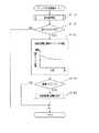
Hereinafter, a first embodiment of the present invention will be described with reference to the drawings. In the present embodiment, an engine control system is constructed for an in-vehicle four-cylinder gasoline engine that is a multi-cylinder internal combustion engine, and in this control system, fuel injection is performed with an engine control electronic control unit (hereinafter referred to as an engine ECU) as a center. Control of quantity, ignition timing, etc. are to be implemented. First, the main configuration of the present control system will be described with reference to FIG.
図1において、エンジン10の吸気ポート近傍には気筒毎に電磁駆動式の燃料噴射弁11が取り付けられている。燃料噴射弁11からエンジン10に燃料が噴射供給されると、各気筒の吸気ポートでは吸入空気と燃料噴射弁11による噴射燃料とが混合されて混合気が形成され、この混合気が吸気バルブ(図示略)の開放に伴い各気筒の燃焼室に導入されて燃焼に供される。 In FIG. 1, an electromagnetically driven fuel injection valve 11 is attached to each cylinder near the intake port of the
エンジン10で燃焼に供された混合気は、排気バルブ(図示略)の開放に伴い排気として排気マニホールド12を介して排出される。排気マニホールド12は気筒毎に分岐した分岐部12aとそれら各分岐部12aを集合させた排気集合部12bとよりなり、排気集合部12bには混合気の空燃比を検出するためのA/Fセンサ13が設けられている。A/Fセンサ13は「空燃比センサ」に相当するものであって、広域の空燃比をリニアに検出する。 The air-fuel mixture used for combustion in the
図示は省略するが、本制御システムでは、前記A/Fセンサ13以外にも吸気管負圧を検出する吸気管負圧センサ、エンジン水温を検出する水温センサ、エンジンの所定クランク角毎にクランク角信号を出力するクランク角センサなど各種センサが設けられており、A/Fセンサ13の検出信号と同様、各種センサの検出信号もエンジンECUに適宜入力されるようになっている。 Although not shown, in this control system, in addition to the A /
上記構成のエンジン10では、A/Fセンサ13の検出信号に基づいて空燃比が算出され、その算出値が目標値に一致するよう気筒毎の燃料噴射量がF/B(フィードバック)制御される。空燃比F/B制御の基本構成を図1で説明すれば、空燃比偏差算出部21では、A/Fセンサ13の検出信号から算出した検出空燃比と別途設定した目標空燃比との偏差が算出され、空燃比F/B制御部22では、その偏差に基づいて空燃比補正係数が算出される。そして、噴射量算出部23では、エンジン回転数やエンジン負荷(例えば吸気管負圧)等に基づいて算出されたベース噴射量や前記空燃比補正係数などから最終噴射量が算出され、その最終噴射量により燃料噴射弁11が制御される。この制御の流れは従来の空燃比F/B制御と同様である。 In the
上述した空燃比F/B制御は、排気マニホールド12の排気集合部12bで検出した空燃比情報に基づいて各気筒の燃料噴射量(空燃比)を制御するものであるが、現実には気筒毎に空燃比がばらつくため、本実施の形態では、A/Fセンサ13の検出値から気筒別空燃比を求め、その気筒別空燃比に基づいて気筒別空燃比制御を実施することとする。その詳細を以下に説明する。 The air / fuel ratio F / B control described above controls the fuel injection amount (air / fuel ratio) of each cylinder based on the air / fuel ratio information detected by the
図1に示すように、空燃比偏差算出部21で算出した空燃比偏差は気筒別空燃比推定部24に入力され、この気筒別空燃比推定部24において気筒別空燃比が推定される。気筒別空燃比推定部24では、排気マニホールド12の排気集合部12bにおけるガス交換に着目して、A/Fセンサ13の検出値を、排気集合部12bにおける流入ガスの気筒別空燃比の履歴とA/Fセンサ13の検出値の履歴とにそれぞれ所定の重みを乗じて加算したものとしてモデル化し、該モデルをもとに気筒別空燃比を推定することとしている。また、オブザーバとしてはカルマンフィルタを用いている。 As shown in FIG. 1, the air-fuel ratio deviation calculated by the air-fuel ratio
より具体的には、排気集合部12bにおけるガス交換のモデルを次の(1)式にて近似する。(1)式中、ysはA/Fセンサ13の検出値、uは排気集合部12bに流入するガスの空燃比、k1〜k4は定数である。 More specifically, a gas exchange model in the

上記(1)式を状態空間モデルに変換すると、次の(2)式が得られる。(2)式中、A,B,C,Dはモデルのパラメータ、YはA/Fセンサ13の検出値、Xは状態変数としての気筒別空燃比、Wはノイズである。 When the above equation (1) is converted into a state space model, the following equation (2) is obtained. In the equation (2), A, B, C, and D are model parameters, Y is a detected value of the A /
また、基準空燃比算出部25では、前記気筒別空燃比推定部24で推定した気筒別空燃比に基づいて基準空燃比が算出される。ここでは、気筒別空燃比の全気筒平均(本実施の形態では第1〜第4気筒の平均値)を基準空燃比としており、新たに気筒別空燃比が算出される度に基準空燃比が更新される。気筒別空燃比偏差算出部26では、気筒別空燃比と基準空燃比との偏差(気筒別空燃比偏差)が算出される。 The reference air-fuel
気筒別空燃比制御部27では、気筒別空燃比偏差算出部26で算出した偏差に基づいて気筒別補正量が算出され、その気筒別補正量により各気筒の最終噴射量が補正される。気筒別空燃比制御部27のより詳しい構成を図2で説明する。 In the cylinder-by-cylinder air-fuel
図2において、気筒毎に算出された気筒別空燃比偏差(図1の気筒別空燃比偏差算出部26の出力)は、第1〜第4の各気筒毎の補正量算出部31,32,33,34にそれぞれ入力される。各補正量算出部31〜34では、気筒別空燃比偏差に基づいて気筒間の空燃比ばらつきが解消されるように、すなわち、該当する気筒の気筒別空燃比が基準空燃比に一致するようにして気筒別補正量が算出される。このとき、各気筒の補正量算出部31〜34で算出された気筒別補正量は全て補正量平均値算出部35に取り込まれ、第1気筒〜第4気筒の各気筒別補正量の平均値が算出される。そして、その補正量平均値により第1気筒〜第4気筒の各気筒別補正量が減量補正される。結果この補正後の気筒別補正量により各気筒の最終噴射量が補正される。 In FIG. 2, the cylinder-by-cylinder air-fuel ratio deviation calculated for each cylinder (the output of the cylinder-by-cylinder air-fuel ratio
上述した空燃比偏差算出部21、空燃比F/B制御部22、噴射量算出部23、気筒別空燃比推定部24、基準空燃比算出部25、気筒別空燃比偏差算出部26及び気筒別空燃比制御部27は、エンジンECU内のマイクロコンピュータにより実現されれば良く、次に、エンジンECUによる気筒別空燃比制御の一連の流れをフローチャートに基づいて説明する。図3は、所定のクランク角度毎(本実施の形態では30°CA毎)に実行されるクランク角同期ルーチンを示すフローチャートである。 The air-fuel ratio
図3において、先ずステップS110では、気筒別空燃比制御を許可又は禁止するための実行条件判定処理を実施する。実行条件判定処理を図4に基づいて詳しく説明すれば、ステップS111では、A/Fセンサ13が使用可能な状態であるか否かを判別する。具体的には、A/Fセンサ13が活性化していること、フェイルしていないこと等を判別する。また、ステップS112では、エンジン水温が所定温度(例えば70℃)以上であるか否かを判別する。そして、A/Fセンサ13が使用可能であり且つエンジン水温が所定温度以上であれば、ステップS113に進む。 In FIG. 3, first, in step S110, an execution condition determination process for permitting or prohibiting the cylinder-by-cylinder air-fuel ratio control is performed. The execution condition determination process will be described in detail with reference to FIG. 4. In step S111, it is determined whether or not the A /
ステップS113では、回転速度とエンジン負荷(例えば吸気管負圧)とをパラメータとする運転領域マップを参照し、今現在のエンジン運転状態が実行領域にあるかどうかを判定する。このとき、高回転域又は低負荷域では気筒別空燃比の推定が困難である、又は推定値の信頼性が低いと考えられるため、かかる運転領域で気筒別空燃比制御が禁止されるようにして、図示の如く実行領域が設定されている。 In step S113, it is determined whether or not the current engine operation state is in the execution region with reference to an operation region map using the rotational speed and engine load (for example, intake pipe negative pressure) as parameters. At this time, it is considered difficult to estimate the cylinder-by-cylinder air-fuel ratio in the high speed range or the low load range, or the estimated value is considered to be low in reliability. As shown in the figure, an execution area is set.
今現在のエンジン運転状態が実行領域にあれば、ステップS114を肯定判別し、ステップS115で実行フラグをONする。実行領域になければ、ステップS114を否定判別し、ステップS116で実行フラグをOFFする。その後本処理を終了する。 If the current engine operating state is in the execution region, an affirmative determination is made in step S114, and the execution flag is turned ON in step S115. If not in the execution area, a negative determination is made in step S114, and the execution flag is turned OFF in step S116. Thereafter, this process is terminated.
図3の説明に戻り、ステップS120では、実行フラグがONであるか否かを判別し、実行フラグがONであることを条件にステップS130に進む。ステップS130では、気筒別空燃比の制御タイミングを決定する。このとき、エンジン負荷(例えば吸気管負圧)をパラメータとするマップを参照し、その時のエンジン負荷に応じて基準クランク角度を決定する。当該マップでは、低負荷域で基準クランク角度が遅角側にシフトされるようになっている。つまり、低負荷域では排気流速が遅くなることが考えられ、故にその遅延分に合わせて基準クランク角度が設定され、その基準クランク角度に基づいて制御タイミングが決定されるようになっている。 Returning to the description of FIG. 3, in step S120, it is determined whether or not the execution flag is ON, and the process proceeds to step S130 on condition that the execution flag is ON. In step S130, the control timing of the cylinder-by-cylinder air-fuel ratio is determined. At this time, a map using the engine load (for example, intake pipe negative pressure) as a parameter is referred to, and the reference crank angle is determined according to the engine load at that time. In the map, the reference crank angle is shifted to the retard side in the low load range. That is, it is conceivable that the exhaust flow velocity becomes slow in the low load region, so that the reference crank angle is set in accordance with the delay, and the control timing is determined based on the reference crank angle.
ここで、基準クランク角度は、気筒別空燃比の推定に用いるA/Fセンサ値を取得するための基準角度位置であり、これはエンジン負荷に応じて変動する。図6で説明すれば、A/Fセンサ値は気筒間の個体差等により変動し、クランク角に同期した所定パターンとなる。この変動パターンはエンジン負荷が小さい場合に遅角側にシフトする。例えば図のa,b,c,dの各タイミングでA/Fセンサ値を取得したい場合に、負荷変動が生じるとA/Fセンサ値が本来欲しい値からずれるが、上記の通り基準クランク角度が可変設定されることにより最適なタイミングでA/Fセンサ値が取得できる。但し、A/Fセンサ値を取り込むこと(例えばA/D変換すること)自体は、必ずしも上記基準クランク角度のタイミングに限定されず、この基準クランク角度よりも短い間隔で実施される構成であっても良い。 Here, the reference crank angle is a reference angle position for acquiring an A / F sensor value used for estimating the cylinder-by-cylinder air-fuel ratio, and this varies depending on the engine load. Referring to FIG. 6, the A / F sensor value fluctuates due to individual differences between the cylinders and has a predetermined pattern synchronized with the crank angle. This variation pattern shifts to the retard side when the engine load is small. For example, when it is desired to acquire the A / F sensor value at each timing of a, b, c, and d in the figure, when the load fluctuation occurs, the A / F sensor value deviates from the originally desired value. By variably setting, the A / F sensor value can be acquired at an optimal timing. However, taking in the A / F sensor value (for example, A / D conversion) itself is not necessarily limited to the timing of the reference crank angle, and is implemented at an interval shorter than the reference crank angle. Also good.
その後、気筒別空燃比の制御タイミング(ステップS140がYES)であることを条件にステップS150に進み、気筒別空燃比制御を実行する。気筒別空燃比制御を図5に基づいて説明する。 Thereafter, the process proceeds to step S150 on condition that the control timing of the cylinder-by-cylinder air-fuel ratio (step S140 is YES), and the cylinder-by-cylinder air-fuel ratio control is executed. The cylinder-by-cylinder air-fuel ratio control will be described with reference to FIG.
図5において、ステップS151では、A/Fセンサ13の検出信号から算出された空燃比を読み込み、続くステップS152では、前記読み込んだ空燃比に基づいて気筒別空燃比を推定する。気筒別空燃比の推定手法については既述の通りである。 In FIG. 5, in step S151, the air-fuel ratio calculated from the detection signal of the A /
その後、ステップS153では、前記推定した気筒別空燃比の全気筒分(本実施の形態では過去4気筒分)の平均値を算出し、その平均値を基準空燃比とする。最後に、ステップS154では、気筒別空燃比と基準空燃比との差に応じて気筒毎に気筒別補正量を算出する。なおこのとき、前記図2で説明したように、全気筒の気筒別補正量が各々算出されると共に全気筒平均値が算出され、気筒別補正量から全気筒平均値を減算した値が、最終的に気筒別補正量とされるようになっている。そして、この気筒別補正量を用いて気筒毎に最終噴射量が補正される。 Thereafter, in step S153, an average value of all the estimated cylinder-by-cylinder air-fuel ratios (for the past four cylinders in the present embodiment) is calculated, and the average value is set as a reference air-fuel ratio. Finally, in step S154, a cylinder-specific correction amount is calculated for each cylinder according to the difference between the cylinder-specific air-fuel ratio and the reference air-fuel ratio. At this time, as described with reference to FIG. 2, the cylinder-by-cylinder correction amount for all cylinders is calculated, the average value for all cylinders is calculated, and the value obtained by subtracting the average value for all cylinders from the cylinder-by-cylinder correction amount is the final value. Therefore, the correction amount is determined by cylinder. Then, the final injection amount is corrected for each cylinder using the correction amount for each cylinder.
図7は、気筒別空燃比制御を実施した場合の空燃比挙動を示すタイムチャートである。図7において、(a)はA/Fセンサ13により検出された空燃比(集合部空燃比)を、(b)は各気筒毎にA/Fセンサを取り付けて計測した気筒別空燃比の実測値を、(c)は第1〜第4気筒の気筒別空燃比の推定値を、(d)は気筒別補正量の挙動を、それぞれ示している。なお本事例では、(b)及び(c)に示すように、全4気筒のうち第1気筒のみが明らかに他と異なる空燃比挙動となっており、図面ではこれを「#1」、他を「#2〜#4」としている。 FIG. 7 is a time chart showing the air-fuel ratio behavior when the cylinder-by-cylinder air-fuel ratio control is performed. In FIG. 7, (a) shows the air-fuel ratio (collection part air-fuel ratio) detected by the A /
(b)及び(c)を比較して分かるように、本実施の形態による気筒別空燃比の推定値は概ね実際の空燃比挙動(実測値)に合致するものとなっている。また、(d)に示すタイミングt1以降では、気筒別補正量が算出される。かかる場合、第1気筒の気筒別補正量が減量側に、他の気筒の気筒別補正量が増量側に設定されることにより、t1以降、気筒間の空燃比ばらつきが解消されるようになっている。 As can be seen by comparing (b) and (c), the estimated value of the cylinder-by-cylinder air-fuel ratio according to the present embodiment substantially matches the actual air-fuel ratio behavior (actually measured value). Further, after the timing t1 shown in (d), the cylinder specific correction amount is calculated. In such a case, by setting the correction amount for each cylinder of the first cylinder to the decrease side and the correction amount for each cylinder of the other cylinder to the increase side, the variation in the air-fuel ratio among the cylinders is resolved after t1. ing.
以上詳述した本実施の形態によれば、以下の優れた効果が得られる。 According to the embodiment described above in detail, the following excellent effects can be obtained.
排気集合部12bにおけるガス流入及び混合に基づき構築したモデルを用いて気筒別空燃比を推定するようにしたため、当該排気集合部12bのガス交換挙動を反映して気筒別空燃比が算出できる。また、当該モデルは、A/Fセンサ13の検出値をその過去の値から予測するモデル(自己回帰モデル)であることから、有限の燃焼履歴(燃焼空燃比)を用いる従来構成とは異なり、精度向上を図る上で履歴を増やすことを要しない。その結果、簡単なモデルを用いることでモデリングの複雑さを解消し、しかも気筒別空燃比を精度良く算出することができるようになる。その結果、ひいては空燃比制御の制御性が向上する。 Since the cylinder-by-cylinder air-fuel ratio is estimated using a model constructed based on the gas inflow and mixing in the
気筒別空燃比の推定にカルマンフィルタ型のオブザーバを用いたため、対ノイズ性能が向上し、気筒別空燃比の推定精度が向上する。 Since the Kalman filter type observer is used for estimating the cylinder-by-cylinder air-fuel ratio, the anti-noise performance is improved, and the estimation accuracy of the cylinder-by-cylinder air-fuel ratio is improved.
気筒別空燃比の制御タイミングをエンジン負荷に応じて可変設定する構成としたため、最適なタイミングでA/Fセンサ値が取得でき、気筒別空燃比の推定精度が向上する。 Since the control timing of the cylinder-by-cylinder air-fuel ratio is variably set according to the engine load, the A / F sensor value can be acquired at the optimum timing, and the accuracy of estimating the cylinder-by-cylinder air-fuel ratio is improved.
また、空燃比F/B制御において、気筒別空燃比(推定値)に基づいて気筒間の空燃比ばらつき量としての気筒別空燃比偏差を算出し、該算出した気筒別空燃比偏差に応じて該当する気筒毎に気筒別補正量を算出する構成としたため、気筒間の空燃比ばらつき量による空燃比制御誤差を減じることができ、精度の良い空燃比制御が実現できる。 Further, in the air-fuel ratio F / B control, a cylinder-by-cylinder air-fuel ratio deviation is calculated as an air-fuel ratio variation amount between cylinders based on the cylinder-by-cylinder air-fuel ratio (estimated value), and the cylinder-by-cylinder air-fuel ratio deviation is calculated. Since the correction amount for each cylinder is calculated for each corresponding cylinder, the air-fuel ratio control error due to the air-fuel ratio variation amount between the cylinders can be reduced, and the air-fuel ratio control with high accuracy can be realized.
また、気筒別補正量の算出においては、気筒別補正量の全気筒平均値を算出してこの全気筒平均値だけ各気筒毎の気筒別補正量を減算補正するようにしたため、通常の空燃比F/B制御との干渉が回避できる。つまり、通常の空燃比F/B制御では、排気集合部12bにおける空燃比検出値が目標値に一致するよう空燃比制御が実施されるのに対し、気筒別空燃比制御では気筒間の空燃比ばらつきを吸収するよう空燃比制御が実施される。 In addition, in calculating the correction amount for each cylinder, the average value for all cylinders of the correction amount for each cylinder is calculated, and the correction amount for each cylinder is subtracted and corrected by this average value for all cylinders. Interference with F / B control can be avoided. In other words, in the normal air-fuel ratio F / B control, the air-fuel ratio control is performed so that the air-fuel ratio detection value in the
(第2の実施の形態)
上記第1の実施の形態では、A/Fセンサ13の検出値に基づいて気筒別空燃比を推定し、該気筒別空燃比(推定値)に基づいて気筒間の空燃比ばらつきをなくすよう気筒別空燃比制御を実施したが、エンジン運転状態によっては気筒別空燃比の推定が困難となる場合がある。気筒別空燃比が推定できない場合、気筒別空燃比制御が実施できなくなるために、気筒間の空燃比ばらつきが解消できないことが懸念される。例えば、エンジン始動直後や、高回転又は低負荷運転時にはこうした事態が生じる。そこで本実施の形態では、気筒間の空燃比ばらつきを学習して該学習により得られた気筒別学習値(空燃比学習値)を、イグニッションOFF後にも記憶内容を保持するスタンバイRAM等のバックアップ用メモリに格納しておき、この気筒別学習値を空燃比制御に適宜用いることとしている。なお、バックアップ用メモリとしてEEPROM等の不揮発性メモリを用いることも可能である。(Second Embodiment)
In the first embodiment, the cylinder-by-cylinder air-fuel ratio is estimated based on the detection value of the A /
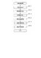
図8は、本実施の形態における気筒別空燃比制御処理を示すフローチャートであり、当該制御処理は、前記図5の処理に置き換えて実施される。なお、図8のステップS201〜S204は、前記図5のステップS151〜S154と同じ処理である。 FIG. 8 is a flowchart showing the cylinder-by-cylinder air-fuel ratio control process in the present embodiment, and the control process is performed in place of the process of FIG. Note that steps S201 to S204 in FIG. 8 are the same processes as steps S151 to S154 in FIG.
図8において、先ずステップS201〜S204では、気筒別補正量を算出する。すなわち、前述したとおり空燃比の読み込み(ステップS201)、気筒別空燃比の推定(ステップS202)、基準空燃比の算出(ステップS203)、気筒別補正量の算出(ステップS204)を実施する。前記図2で説明したとおり、気筒別補正量は、気筒別空燃比偏差に基づいて算出した第1〜第4気筒補正量の平均値(全気筒平均値)と、第1〜第4気筒補正量との差から算出される。 In FIG. 8, first, in steps S201 to S204, the correction amount for each cylinder is calculated. That is, as described above, the air-fuel ratio is read (step S201), the cylinder-by-cylinder air-fuel ratio is estimated (step S202), the reference air-fuel ratio is calculated (step S203), and the cylinder-by-cylinder correction amount is calculated (step S204). As described with reference to FIG. 2, the cylinder specific correction amounts are the average value (all cylinder average value) of the first to fourth cylinder correction amounts calculated based on the cylinder specific air-fuel ratio deviation, and the first to fourth cylinder corrections. Calculated from the difference from the quantity.
その後、ステップS210では、気筒別学習値の更新処理を実施し、続くステップS220では、気筒別学習値を反映させるなどして気筒毎に最終な燃料噴射量を算出する。但し、ステップS210,S220の詳細については後述する。 Thereafter, in step S210, the cylinder-by-cylinder learning value is updated, and in step S220, the final fuel injection amount is calculated for each cylinder by reflecting the cylinder-by-cylinder learning value. However, details of steps S210 and S220 will be described later.
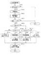
図9は、前記ステップS210における気筒別学習値の更新処理を示すフローチャートである。図9において、ステップS211では、学習の実行条件が成立しているか否かを判別する。具体的には、
(イ)今現在、気筒別空燃比制御が実行されていること、
(ロ)エンジン水温が所定温度以上(例えばマイナス10℃以上)であること、
(ハ)空燃比変動量が所定値以下であり、空燃比安定条件が成立していること、
を学習実行条件とし、上記(イ)〜(ハ)が何れも満たされる場合に、学習実行条件が成立したとされる。学習実行条件が成立した場合には学習値更新が許可され、学習実行条件が成立しない場合に学習値更新が禁止される。FIG. 9 is a flowchart showing the cylinder-by-cylinder learning value update process in step S210. In FIG. 9, in step S211, it is determined whether or not a learning execution condition is satisfied. In particular,
(B) Currently, the cylinder-by-cylinder air-fuel ratio control is being executed,
(B) The engine water temperature is higher than a predetermined temperature (for example, minus 10 ° C. or higher),
(C) The air-fuel ratio fluctuation amount is not more than a predetermined value, and the air-fuel ratio stabilization condition is satisfied,
Is the learning execution condition, and the learning execution condition is satisfied when all of the above (a) to (c) are satisfied. When the learning execution condition is satisfied, the learning value update is permitted, and when the learning execution condition is not satisfied, the learning value update is prohibited.
上記(イ)の条件が満たされるには、気筒別空燃比制御の実行条件が成立していることが前提であり、前記図4の実行条件判定処理にて説明したように、A/Fセンサ13が活性化していること、フェイル(故障)していないこと等が上記(イ)の条件に含まれる。 In order to satisfy the condition (A), it is premised that the execution condition of the cylinder-by-cylinder air-fuel ratio control is satisfied. As described in the execution condition determination process of FIG. The condition (a) includes that 13 is activated, has not failed (failed), and the like.
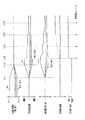
上記(ハ)の条件を図11により説明する。つまり、検出空燃比(A/F)の今回値と前回値との差ΔA/F1(絶対値)が所定値TH1未満であり、且つ検出空燃比の今回値と720°CA前値との差ΔA/F2(絶対値)が所定値TH2未満である場合に、上記(ハ)の空燃比安定条件が成立した判定することとしている。例えば、検出空燃比が図11の(a)のように変化する時、ΔA/F1,ΔA/F2は(b),(c)となり、その結果、t11〜t12以外の期間で空燃比安定条件が成立した旨判定される。 The condition (c) will be described with reference to FIG. That is, the difference ΔA / F1 (absolute value) between the current value of the detected air-fuel ratio (A / F) and the previous value is less than the predetermined value TH1, and the difference between the current value of the detected air-fuel ratio and the previous value of 720 ° CA. When ΔA / F2 (absolute value) is less than a predetermined value TH2, it is determined that the air-fuel ratio stabilization condition (c) is satisfied. For example, when the detected air-fuel ratio changes as shown in FIG. 11A, ΔA / F1 and ΔA / F2 become (b) and (c), and as a result, the air-fuel ratio stabilization condition in a period other than t11 to t12. Is determined to have been established.
上記(イ)〜(ハ)以外にも、高回転時や低負荷時など、気筒別空燃比の推定精度が低下すると考えられる条件を設定し、かかる条件下で学習値更新を禁止するようにしても良い。以上のように学習実行条件を規定することで、気筒別学習値の誤学習の防止が可能となる。 In addition to the above (a) to (c), a condition that the estimated accuracy of the air-fuel ratio for each cylinder is lowered, such as at high revolution or low load, is set, and the learning value update is prohibited under such conditions. May be. By defining the learning execution condition as described above, it is possible to prevent erroneous learning of the learning value for each cylinder.
学習実行条件が成立している場合、ステップS212に進み、例えばエンジン回転数や負荷をパラメータとして今回学習を実施する学習領域を決定する。その後、ステップS213では、気筒毎に気筒別補正量のなまし値を算出する。具体的には、次式を用いて補正量なまし値を算出する。但し、Kはなまし係数であり、例えばK=0.25である。
補正量なまし値=前回のなまし値+K×(今回の補正量−前回のなまし値)
その後、ステップS214では、今回の処理が気筒別学習値の更新タイミングであるか否かを判別する。この更新タイミングは、気筒別学習値の更新周期が少なくとも気筒別補正量の算出周期よりも長くなるよう設定されるものであれば良く、例えば、タイマ等に設定された所定時間が経過した時に更新タイミングである旨判別される。気筒別学習値の更新タイミングであれば、後続のステップS215に進み、更新タイミングでなければ、そのまま本処理を終了する。When the learning execution condition is satisfied, the process proceeds to step S212, and a learning area in which the current learning is performed is determined using, for example, the engine speed and the load as parameters. Thereafter, in step S213, the smoothing value of the cylinder-specific correction amount is calculated for each cylinder. Specifically, the correction amount smoothing value is calculated using the following equation. However, K is an annealing coefficient, for example, K = 0.25.
Correction amount smoothing value = previous smoothing value + K x (current correction amount-previous smoothing value)
Thereafter, in step S214, it is determined whether or not the current process is the update timing of the learning value for each cylinder. The update timing may be set so that the update period of the learning value for each cylinder is set to be longer than at least the calculation period of the correction amount for each cylinder. For example, the update timing is updated when a predetermined time set in a timer or the like has elapsed. It is determined that it is timing. If it is the update timing of the learning value for each cylinder, the process proceeds to the subsequent step S215.
ステップS215では、前記算出した気筒毎の補正量なまし値の絶対値が所定値THA以上であるか否かを判別する。本実施の形態では、所定値THAは、気筒別空燃比(推定値)の全気筒平均値と気筒別空燃比との差が空気過剰率λで0.01以上となる場合の相当値としている。 In step S215, it is determined whether or not the absolute value of the calculated correction amount smoothing value for each cylinder is equal to or greater than a predetermined value THA. In the present embodiment, the predetermined value THA is an equivalent value when the difference between the cylinder average air-fuel ratio (estimated value) and the cylinder-by-cylinder air-fuel ratio is 0.01 or more in the excess air ratio λ. .
補正量なまし値(絶対値)≧THAであれば、ステップS216に進み、学習値更新量を算出する。このとき、学習値更新量は、例えば図12の関係を用い、その時の補正量なまし値に基づいて算出され、基本的に補正量なまし値が大きいほど学習値更新量が大きい値とされる。なお、図12の関係では、補正量なまし値<aでは学習値更新量が0とされ、このaは前記ステップS215の所定値THAに相当する。その後、ステップS217では、気筒別学習値の更新処理を実施する。すなわち、気筒別学習値の前回値に学習値更新量を加算し、その結果を新たな気筒別学習値とする。 If the correction amount smoothing value (absolute value) ≧ THA, the process proceeds to step S216, and the learning value update amount is calculated. At this time, the learning value update amount is calculated based on the correction amount smoothing value at that time, for example, using the relationship of FIG. 12, and basically the larger the correction amount smoothing value, the larger the learning value update amount. The In the relationship of FIG. 12, when the correction amount smoothing value <a, the learning value update amount is 0, and this a corresponds to the predetermined value THA in step S215. Thereafter, in step S217, a process for updating the learning value for each cylinder is performed. That is, the learning value update amount is added to the previous value of the learning value for each cylinder, and the result is used as a new learning value for each cylinder.
また、補正量なまし値(絶対値)<THAであれば、ステップS218に進み、学習完了フラグをONする。 If the correction amount smoothed value (absolute value) <THA, the process proceeds to step S218, and the learning completion flag is turned ON.
最後に、ステップS219では、気筒別学習値、学習完了フラグをスタンバイRAMに記憶する。このとき、気筒別学習値及び学習完了フラグは、複数に区分された運転領域毎に記憶される。その概要を図13に表す。図13では、エンジン運転領域を負荷レベル(例えば吸気管圧力PM)毎に領域0,領域1,領域2,領域3,領域4に区分しており、各領域0〜4毎に気筒別学習値及び学習完了ラグが記憶されることを表している。領域0は学習未完了、領域1〜4は学習完了の状態であり、領域1〜4の気筒別学習値をそれぞれLRN1,LRN2,LRN3,LRN4としている。また、各領域0〜4の領域中心負荷、すなわち領域を代表する負荷を、それぞれPM0,PM1,PM2,PM3,PM4としている。領域区分には、負荷以外にも、エンジン回転数、水温、吸入空気量、要求噴射量等を適宜用いることができる。 Finally, in step S219, the learning value for each cylinder and the learning completion flag are stored in the standby RAM. At this time, the cylinder-by-cylinder learning value and the learning completion flag are stored for each of the operation regions divided into a plurality. The outline is shown in FIG. In FIG. 13, the engine operation region is divided into
また、図10は、前記図8のステップS220における気筒別学習値の反映処理を示すフローチャートである。図10において、ステップS221では、その時のエンジン運転状態に基づいて学習反映値を算出する。このとき、学習反映値は、前記図13のように運転領域毎に記憶保持された気筒別学習値を用い、それら領域間の気筒別学習値の線形補間により求められる。学習反映値の求め方を図13を用いて説明する。 FIG. 10 is a flowchart showing the process of reflecting the learning value for each cylinder in step S220 of FIG. In FIG. 10, in step S221, a learning reflection value is calculated based on the engine operating state at that time. At this time, the learning reflection value is obtained by the cylinder-by-cylinder learning value stored and held for each operation region as shown in FIG. 13 and linear interpolation of the cylinder-by-cylinder learning value between these regions. A method of obtaining the learning reflection value will be described with reference to FIG.
一例として、その時の負荷が「PMa」である場合、領域2,3の気筒別学習値LRN2,LRN3と、領域2,3の中心負荷であるPM2,PM3とを用い、次の(4)式により学習反映値FLRNを算出する。 As an example, when the load at that time is “PMa”, the learning values LRN2 and LRN3 for the cylinders in the
ステップS222では、前記算出した学習反映値を最終の燃料噴射量TAUに反映させる。具体的には、基本噴射量TP、空燃比補正係数FAF、気筒別補正量FK、学習反映値FLRN、その他の補正係数FALLを用い、燃料噴射量TAUを算出する(TAU=TP×FAF×FK×FLRN×FALL)。なおこのとき、FAF補正と学習補正とが干渉しないように、空燃比補正係数FAFを学習反映値FLRN分だけ減補正すると良い。 In step S222, the calculated learning reflection value is reflected in the final fuel injection amount TAU. Specifically, the fuel injection amount TAU is calculated using the basic injection amount TP, the air-fuel ratio correction coefficient FAF, the cylinder specific correction amount FK, the learning reflection value FLRN, and other correction coefficients FALL (TAU = TP × FAF × FK). × FLRN × FALL). At this time, the air-fuel ratio correction coefficient FAF may be reduced and corrected by the learning reflection value FLRN so that the FAF correction and the learning correction do not interfere with each other.
図14は、気筒別学習値が更新される過程を説明するためのタイムチャートである。図14では、全4気筒のうち第1気筒の気筒別空燃比だけが明らかに他の気筒と相違しており、図面ではこれを「#1」、他を「#2〜#4」としている。 FIG. 14 is a time chart for explaining the process of updating the learning value for each cylinder. In FIG. 14, only the air-fuel ratio by cylinder of the first cylinder among all four cylinders is clearly different from other cylinders. In the drawing, this is “# 1” and the others are “# 2 to # 4”. .
図14において、タイミングt21以降、気筒別補正量が算出され、それに伴い気筒間の空燃比ばらつきに応じた気筒別補正量が図示の如く算出される。そして、タイミングt22では、気筒間の空燃比ばらつきが解消され、気筒別空燃比がほぼ均一化される。 In FIG. 14, the correction amount for each cylinder is calculated after the timing t21, and accordingly, the correction amount for each cylinder corresponding to the variation in the air-fuel ratio among the cylinders is calculated as shown. At timing t22, the air-fuel ratio variation among the cylinders is eliminated, and the cylinder-by-cylinder air-fuel ratio is substantially uniformized.
その後、タイミングt23では、学習実行条件が成立し、それ以降気筒別学習値の算出及び更新処理が実施される。図中、タイミングt23,t24,t25,t26が学習更新タイミングである。学習更新周期は、気筒別補正量の算出周期よりも長いため、急な気筒別学習値の更新による誤学習が抑制される。t23〜t26の各タイミングでは、その都度の各気筒の補正量なまし値の大きさに応じた分だけ気筒別学習値が更新される。そして、各気筒の補正量なまし値が所定値THA未満になると、学習完了とされ学習完了フラグがセットされる(図示は省略)。このとき、気筒別学習値が所定時間を隔てて更新されるため、気筒別学習値は気筒間ばらつきに逐次対応できないことも考えられるが、この気筒間ばらつきは現実には空燃比補正係数FAF等により解消される。 Thereafter, at timing t23, the learning execution condition is satisfied, and thereafter, the calculation value and the update process of the cylinder-by-cylinder learning value are performed. In the figure, timings t23, t24, t25, and t26 are learning update timings. Since the learning update period is longer than the calculation period of the cylinder-by-cylinder correction amount, erroneous learning due to a sudden update of the cylinder-by-cylinder learning value is suppressed. At each timing from t23 to t26, the learning value for each cylinder is updated by an amount corresponding to the magnitude of the correction amount smoothing value of each cylinder. When the correction amount smoothing value of each cylinder becomes less than the predetermined value THA, learning is completed and a learning completion flag is set (not shown). At this time, since the learning value for each cylinder is updated at a predetermined time interval, the learning value for each cylinder may not be able to sequentially cope with the variation between the cylinders. Is eliminated.
以上第2の実施の形態によれば、気筒毎の気筒別補正量に応じて気筒別学習値(空燃比学習値)を適宜算出し、スタンバイRAM等に記憶保持する構成としたため、気筒別空燃比の推定値が得られない場合であっても、気筒別空燃比制御が可能となり、気筒間の空燃比ばらつきが解消できる。 As described above, according to the second embodiment, the cylinder-by-cylinder learning value (air-fuel ratio learning value) is appropriately calculated according to the cylinder-by-cylinder correction amount and stored in the standby RAM or the like. Even when the estimated value of the fuel ratio cannot be obtained, the cylinder-by-cylinder air-fuel ratio control can be performed, and variations in the air-fuel ratio among the cylinders can be eliminated.
気筒別学習値の1回当たりの更新幅(学習値更新量)がその都度の気筒別補正量に応じて可変設定されるため、気筒別補正量が大きい(すなわち気筒間における空燃比ばらつきが大きい)場合であっても、比較的短時間で学習を完了することができる。また、気筒間における空燃比ばらつきが解消され、気筒別補正量が小さくなる場合には、小刻みにすなわち慎重に気筒別学習値を更新することができるため、学習の精度を高めることができる。 Since the update range (learning value update amount) for each learning value for each cylinder is variably set according to the correction amount for each cylinder, the correction amount for each cylinder is large (that is, the variation in air-fuel ratio among cylinders is large). ), The learning can be completed in a relatively short time. Further, when the variation in air-fuel ratio among cylinders is eliminated and the correction amount for each cylinder becomes small, the learning value for each cylinder can be updated in small increments, that is, the learning accuracy can be improved.
(第3の実施の形態)
燃料タンク内で発生した蒸発燃料をキャニスタ(燃料吸着装置)に一旦吸着し、その後エンジン吸気系に放出(パージ)して燃焼室内で燃焼させるようにした蒸発燃料放出装置が従来より知られており、本装置を備えた制御システムでは、蒸発燃料の放出量(パージ量)に応じて燃料噴射弁(燃料噴射装置)による燃料噴射量を補正することが提案されている。しかしながら多気筒エンジンの場合、キャニスタから燃焼室までの吸気経路の形状や長さ等が異なることなどが原因で、各気筒に分配されるパージ量がばらつき、結果として空燃比F/B制御が不安定になるという問題がある。(Third embodiment)
2. Description of the Related Art Conventionally, there is known an evaporative fuel discharge device in which evaporative fuel generated in a fuel tank is once adsorbed to a canister (fuel adsorber), then released (purged) into an engine intake system and burned in a combustion chamber. In a control system equipped with this device, it has been proposed to correct the fuel injection amount by the fuel injection valve (fuel injection device) in accordance with the amount of evaporated fuel released (purge amount). However, in the case of a multi-cylinder engine, the amount of purge distributed to each cylinder varies due to differences in the shape and length of the intake path from the canister to the combustion chamber, and as a result, the air-fuel ratio F / B control is not effective. There is a problem of becoming stable.
因みに、特開2001−173485号公報では、気筒間のパージ分配率を予め考慮してパージ分配補正係数を設定しておき、この補正係数を用いて気筒毎に噴射量を補正する構成としている。しかしながらかかる構成では、気筒間のパージ分配率を見込みで設定しているに過ぎない。すなわち、パージ分配補正係数等のパラメータは、基本的にシミュレーション又は実験により求められたデータを基に算出されるようになっていた。従って、エンジン機差や経年変化には対応できず、長期にわたりエミッションの悪化を防止したり、パージ分配の気筒間ばらつきに起因する運転性能悪化を防止したりすることができなかった。 Incidentally, in Japanese Patent Laid-Open No. 2001-173485, a purge distribution correction coefficient is set in consideration of the purge distribution ratio between cylinders in advance, and the injection amount is corrected for each cylinder using this correction coefficient. However, in such a configuration, the purge distribution ratio between the cylinders is merely set with an expectation. That is, parameters such as the purge distribution correction coefficient are basically calculated based on data obtained by simulation or experiment. Therefore, it has not been possible to cope with engine machine differences and aging, and it has been impossible to prevent deterioration of emissions over a long period of time or to prevent deterioration of operating performance due to variations in purge distribution among cylinders.
そこで本実施の形態では、パージ実行時/パージ停止時の気筒別補正量(該気筒別補正量により算出される気筒別学習値を含む)に基づいて蒸発燃料の気筒別分配率を算出し、該気筒別分配率をパージ制御に反映する。そしてこれにより、エミッションの改善や運転性能悪化の防止を図ることとする。 In this embodiment, therefore, the cylinder-by-cylinder distribution ratio of the evaporated fuel is calculated based on the cylinder-by-cylinder correction amount (including the cylinder-by-cylinder learning value calculated by the cylinder-by-cylinder correction amount) at the time of purge execution / purge stop. The distribution ratio for each cylinder is reflected in the purge control. As a result, emissions are improved and driving performance is prevented from deteriorating.
ここで、蒸発燃料放出装置を備えたエンジンの構成を図15に基づいて説明する。図15では、前記図1の構成に対して蒸発燃料放出装置を付加した構成を図示している。 Here, the configuration of the engine provided with the evaporated fuel discharge device will be described with reference to FIG. FIG. 15 shows a configuration in which an evaporated fuel discharge device is added to the configuration of FIG.
図15において、燃料タンク51には導管52の一端が接続され、導管52の他端にはキャニスタ53が接続されている。キャニスタ53には、燃料タンク51内で発生した蒸発燃料を吸着するための例えば活性炭からなる吸着剤が多数収納されており、その一部に外気を導入するための大気導入孔54が設けられている。また、キャニスタ53は、パージ配管55を通じて吸気管15のサージタンクに接続されており、パージ配管55の途中には電磁駆動式のパージ制御弁56が設けられている。パージ制御弁56が開放されることによりパージ配管55に吸気負圧が作用し、その際、大気導入孔54を通じてキャニスタ53に外気が導入されることで、キャニスタ53内の吸着剤から吸着燃料が離脱して吸気管15(サージタンク)に放出される。 In FIG. 15, one end of a
エンジンECU60には、A/Fセンサ13の検出信号をはじめ、その他図示しない各種のセンサ検出信号が入力される。エンジンECU60は、前記各実施の形態で説明したように、気筒別空燃比の推定、該気筒別空燃比を用いた空燃比F/B制御、気筒別学習値の算出を適時実施する。また、エンジン運転状態等に基づいてパージ制御弁56をデューティ駆動し、蒸発燃料のパージ量を適正に制御する。 The
本実施の形態では、気筒別学習値の更新の際、それがパージ実行時の学習値であるか、パージ停止時の学習値であるかを判定し、パージ実行時/パージ停止時の各々について気筒別学習値を更新する。具体的には、エンジンECU60が前記図9に代えて図16に示す気筒別学習値の更新処理を実行する。但し、図16には前記図9と同じ処理も含まれており、重複する処理については詳細な説明を割愛する。 In this embodiment, when the learning value for each cylinder is updated, it is determined whether it is a learning value at the time of purge execution or a learning value at the time of purge stop. Update the learning value for each cylinder. Specifically, the
図16において、ステップS301では、学習の実行条件が成立しているか否かを判別する(前記ステップS211と同様)。学習実行条件が成立している場合、ステップS302では今回学習を実施する学習領域を決定し、続くステップS303では、気筒毎に気筒別補正量のなまし値を算出する(前記ステップS212,S213と同様)。そして、ステップS304では、今回の処理が気筒別学習値の更新タイミングであるか否かを判別する(ステップS214と同様)。 In FIG. 16, in step S301, it is determined whether or not a learning execution condition is satisfied (similar to step S211). When the learning execution condition is satisfied, a learning area for performing the current learning is determined in step S302, and in step S303, the smoothing value of the cylinder-specific correction amount is calculated for each cylinder (steps S212 and S213). The same). In step S304, it is determined whether or not the current process is the update timing of the learning value for each cylinder (similar to step S214).
気筒別学習値の更新タイミングの場合、ステップS305では、今現在、パージ実行中であるか否かを判別する。パージ実行中であれば、ステップS306〜S309においてパージ実行中気筒別学習値の更新処理を実行し、パージ停止中であれば、ステップS310〜S313においてパージ停止中気筒別学習値の更新処理を実行する。 In the case of the update timing of the learning value for each cylinder, in step S305, it is determined whether or not purge is currently being executed. If purging is in progress, the learning value update process for each cylinder being purged is executed in steps S306 to S309, and if purging is stopped, the learning value for each cylinder being purged is updated in steps S310 to S313. To do.
すなわち、パージ実行中において、ステップS306では、補正量なまし値(絶対値)≧THAであるか否かを判別し、YESの場合にステップS307に進んで学習値更新量を算出する(前記ステップS215,S216と同じ)。続くステップS308では、パージ実行中気筒別学習値の前回値に学習値更新量を加算し、その結果を新たなパージ実行中気筒別学習値として更新する。また、補正量なまし値(絶対値)<THAであれば、ステップS309に進み、パージ実行中学習完了フラグをONする。 That is, during purge execution, in step S306, it is determined whether or not the correction amount smoothing value (absolute value) ≧ THA, and if YES, the process proceeds to step S307 to calculate the learning value update amount (step S307). The same as S215 and S216). In the subsequent step S308, the learning value update amount is added to the previous value of the purged cylinder specific learning value, and the result is updated as a new purged cylinder specific learning value. If the correction amount smoothed value (absolute value) <THA, the process proceeds to step S309, and the purge completion learning completion flag is turned ON.
一方、パージ停止中において、ステップS310では、補正量なまし値(絶対値)≧THAであるか否かを判別し、YESの場合にステップS311に進んで学習値更新量を算出する(前記ステップS215,S216と同じ)。続くステップS312では、パージ停止中気筒別学習値の前回値に学習値更新量を加算し、その結果を新たなパージ停止中気筒別学習値として更新する。また、補正量なまし値(絶対値)<THAであれば、ステップS313に進み、パージ停止中学習完了フラグをONする。 On the other hand, during the purge stop, in step S310, it is determined whether or not the correction amount smoothing value (absolute value) ≧ THA, and if YES, the process proceeds to step S311 to calculate the learning value update amount (the step). The same as S215 and S216). In the subsequent step S312, the learning value update amount is added to the previous value of the purge-in-cylinder learning value, and the result is updated as a new purge-in-cylinder learning value. If the correction amount smoothing value (absolute value) <THA, the process proceeds to step S313, and the learning stop flag during purge stop is turned ON.
最後に、ステップS314では、パージ実行中/パージ停止中の各気筒別学習値、各学習完了フラグをスタンバイRAMに記憶する。このとき、各気筒別学習値及び各学習完了フラグは、複数に区分されたエンジン運転領域毎に記憶される。又は、各気筒別学習値及び各学習完了フラグを、その都度のパージ条件(パージ量やパージ濃度等)に応じて区分した領域毎に記憶するようにしても良い。 Finally, in step S314, the learning value for each cylinder during purge execution / purge stop and the learning completion flag are stored in the standby RAM. At this time, the learning value for each cylinder and the learning completion flag are stored for each engine operation region divided into a plurality. Alternatively, the learning value for each cylinder and the learning completion flag may be stored for each region divided according to the purge conditions (purge amount, purge concentration, etc.) each time.
次に、蒸発燃料を放出するためのパージ制御手順について説明する。図17は、パージ率の算出処理を示すフローチャートであり、本処理は所定の時間周期(例えば4ms周期)でエンジンECU60のベースルーチンで実行される。 Next, a purge control procedure for releasing evaporated fuel will be described. FIG. 17 is a flowchart showing a purge rate calculation process, and this process is executed by a base routine of the
図17において、先ずステップS401では、今現在、空燃比F/B制御の実行中であるか否かを判別する。このとき、例えばエンジン始動時でないこと、A/Fセンサ13が活性化していること、燃料カット中でないこと等を条件に空燃比F/B制御が実行されていれば、ステップS401が肯定判別される。続くステップS402では、エンジン水温が所定温度(例えば50℃)以上であるか否かを判別する。ステップS401,S402が共にYESの場合、ステップS403に進み、パージ実行フラグXPGRに1をセットする。 In FIG. 17, first, in step S401, it is determined whether the air-fuel ratio F / B control is currently being executed. At this time, for example, if the air-fuel ratio F / B control is being executed on the condition that the engine is not started, the A /
その後、ステップS404では、パージ率PGRの算出処理を実施する。このとき、空燃比補正係数に基づいてパージ率PGRを算出すると良く、例えば空燃比補正係数が基準値(1.0)に対してどの程度離れているかに応じてパージ率PGRを増減させる。より具体的には、空燃比補正係数の基準値を中心に、当該基準値を含む第1領域と、この第1領域から順に離れる第2領域と第3領域とを設けておき、空燃比補正係数が第1領域にあればパージ率PGRを所定値だけ増加させ、第2領域にあればパージ率PGRをそのまま保持し、第3領域にあればパージ率PGRを所定値だけ減少させる。つまり、空燃比補正係数が基準値付近で安定していれば、パージ率PGRが増加され、空燃比補正係数が基準値から大きく離れると、逆にパージ率PGRが減少される。 Thereafter, in step S404, a purge rate PGR calculation process is performed. At this time, the purge rate PGR may be calculated based on the air-fuel ratio correction coefficient. For example, the purge rate PGR is increased or decreased according to how far the air-fuel ratio correction coefficient is from the reference value (1.0). More specifically, centering on the reference value of the air-fuel ratio correction coefficient, a first region including the reference value, a second region and a third region that are sequentially separated from the first region are provided, and the air-fuel ratio correction is performed. If the coefficient is in the first region, the purge rate PGR is increased by a predetermined value, if it is in the second region, the purge rate PGR is held as it is, and if it is in the third region, the purge rate PGR is decreased by a predetermined value. That is, if the air-fuel ratio correction coefficient is stable near the reference value, the purge rate PGR is increased, and if the air-fuel ratio correction coefficient is far from the reference value, the purge rate PGR is decreased.
その後、ステップS405では、パージ率PGRの上下限チェックを実施する。このとき、例えばPGR上限値は、パージ実行時間が長いほど大きくする(但し、例えば最大5分とする)。或いは、エンジン水温等によりPGR上限値を設定しても良い。 Thereafter, in step S405, the upper and lower limits of the purge rate PGR are checked. At this time, for example, the upper limit value of the PGR is increased as the purge execution time is longer (however, for example, 5 minutes at the maximum). Alternatively, the PGR upper limit value may be set by the engine water temperature or the like.
また、ステップS401,S402の何れかがNOの場合、ステップS406でパージ実行フラグXPGRを0にリセットすると共に、ステップS407でパージ率PGRを0とする。 If either of steps S401 and S402 is NO, the purge execution flag XPGR is reset to 0 in step S406, and the purge rate PGR is set to 0 in step S407.
また、図18は、パージ制御弁駆動処理を示すフローチャートであり、本処理はエンジンECU60において例えば100ms毎の時間割込みにより実行される。 FIG. 18 is a flowchart showing the purge control valve drive process. This process is executed by the
図18において、先ずステップS501では、パージ実行フラグXPGRが1であるか否かを判別し、続くステップS502では今現在、燃料カット中であるか否かを判別する。XPGR=0又は燃料カット中である場合、ステップS503に進み、パージ制御弁56の駆動デューティDutyを0とする。 In FIG. 18, first, in step S501, it is determined whether or not the purge execution flag XPGR is 1. In subsequent step S502, it is determined whether or not the fuel is currently being cut. If XPGR = 0 or the fuel is being cut, the process proceeds to step S503, and the drive duty Duty of the
また、XPGR=1で且つ燃料カット中でない場合、ステップS504に進み、その都度のパージ率PGRに基づいてパージ制御弁56の駆動デューティDutyを算出する。このとき、パージ制御弁56の駆動周期を100msとして次式によりDutyを算出する。 If XPGR = 1 and the fuel is not being cut, the process proceeds to step S504, and the drive duty Duty of the
Duty=(PGR/PGRfo)×(100ms−Pv)×Ppa+Pv
上式において、PGRfoはパージ制御弁56の全開時における各運転状態でのパージ率、Pvはバッテリ電圧の変動に対する電圧補正値、Ppaは大気圧の変動に対する大気圧補正値である。Duty = (PGR / PGRfo) × (100 ms−Pv) × Ppa + Pv
In the above equation, PGRfo is a purge rate in each operation state when the
その後、ステップS505では、パージ制御弁56の駆動デューティDutyを補正するためのDuty補正処理を実行する。ステップS506では、Duty出力を行い、当該Dutyによりパージ制御弁56を駆動する。図19には、前記ステップS505のDuty補正処理を示しており、以下その内容を説明する。 Thereafter, in step S505, a duty correction process for correcting the drive duty duty of the
図19において、ステップS601では、Duty補正の実行条件が成立しているか否かを判別する。このとき、前記図16の処理にて既にパージ実行中気筒別学習値とパージ停止中気筒別学習値とが各々算出され、学習完了していれば補正条件成立とする。条件成立の場合、後続のステップS602に進み、条件不成立の場合、そのまま本処理を終了する。 In FIG. 19, in step S601, it is determined whether or not a duty correction execution condition is satisfied. At this time, the learning value for each cylinder under purge and the learning value for each cylinder during purge stop are already calculated in the process of FIG. 16, and if the learning is completed, the correction condition is satisfied. If the condition is satisfied, the process proceeds to the subsequent step S602. If the condition is not satisfied, the process is terminated.
ステップS602では、キャニスタ53から吸気管15に放出される蒸発燃料の気筒別分配率を算出する。このとき、気筒毎の気筒別補正量、パージ実行中気筒別学習値及びパージ停止中気筒別学習値に基づいて気筒毎に分配率を算出することとしており、具体的には次の手法を用いる。例えば第1気筒においてその時々の気筒別補正量をA1、パージ実行中気筒別学習値をB1、パージ停止中気筒別学習値をC1とした場合、次式により第1気筒補正量偏差を算出する。 In step S602, the cylinder-by-cylinder distribution rate of the evaporated fuel discharged from the
第1気筒補正量偏差=C1−(A1+B1)
上式によれば、パージ停止中の補正量(C1)とパージ実行中の補正量(A1+B1)との差から補正量偏差が算出される。また、第2〜第4気筒についても同様に、第2〜第4気筒補正量偏差を算出する。そして、次式により第1気筒分配率を算出する。First cylinder correction amount deviation = C1- (A1 + B1)
According to the above equation, the correction amount deviation is calculated from the difference between the correction amount (C1) during purge stop and the correction amount (A1 + B1) during purge execution. Similarly, the second to fourth cylinder correction amount deviations are calculated for the second to fourth cylinders. Then, the first cylinder distribution ratio is calculated by the following equation.
第1気筒分配率=第1気筒補正量偏差/Σ全気筒の補正量偏差
第2〜第4気筒についても同様に、第2〜第4気筒分配率を算出する。要するに、パージ停止時と比較してパージ実行時には実際に各気筒に分配された燃料分だけ補正量が変動し、パージ停止時と差が生じる(例えば第1気筒補正量偏差に相当)。従って、各気筒の補正量偏差を用いることで、エンジン機差や経時変化等に関係なく気筒別分配率が算出できる。First cylinder distribution ratio = first cylinder correction amount deviation / Σ correction amount deviation of all cylinders Similarly, the second to fourth cylinder distribution ratios are calculated. In short, the correction amount fluctuates by the amount of fuel actually distributed to each cylinder when purging is performed as compared to when the purge is stopped, and a difference from the purge stop occurs (for example, corresponding to the first cylinder correction amount deviation). Therefore, by using the correction amount deviation of each cylinder, it is possible to calculate the cylinder-by-cylinder distribution rate regardless of the engine machine difference or the change with time.
そして気筒別分配率の算出後、ステップS603では、第1〜第4気筒分配率のうち最大のものと最小のものとの差(MAX−MIN)が所定値α以上であるか否かを判別する。所定値α以上の場合、ステップS604に進み、駆動デューティDutyを所定ガード値でガードする。つまり、第1〜第4気筒分配率のばらつきが過剰に大きいと、気筒毎の発生トルクが変動するという不都合が生じるため、Dutyガードを実施する(Duty=0とすることも可能である)。このとき、エンジン負荷が低いほど、パージ燃料に起因するトルク変動が生じやすいため、低負荷域ほど所定値αを小さくすると良い。 After calculating the cylinder-by-cylinder distribution ratio, in step S603, it is determined whether or not the difference (MAX−MIN) between the maximum and minimum ones of the first to fourth cylinder distribution ratios is greater than or equal to a predetermined value α. To do. If it is equal to or larger than the predetermined value α, the process proceeds to step S604, and the drive duty Duty is guarded with a predetermined guard value. That is, if the variation in the distribution ratios of the first to fourth cylinders is excessively large, there is a disadvantage that the torque generated for each cylinder fluctuates, so duty guard is implemented (Duty = 0 can also be set). At this time, as the engine load is lower, torque fluctuation caused by the purge fuel is more likely to occur. Therefore, it is preferable to decrease the predetermined value α in the lower load region.
また、ステップS605では、第1〜第4気筒分配率のうち最大のものと最小のものとの差(MAX−MIN)が所定値β以上であるか否かを判別する(なお、β<αである)。所定値β以上の場合、ステップS606に進み、デューティ補正量KDを算出する。このとき、デューティ補正量KDの前回値から所定値ΔDを減算し、その結果をデューティ補正量KDの今回値とする(KD=KD前回値−ΔD)。 In step S605, it is determined whether or not the difference (MAX−MIN) between the maximum and minimum of the first to fourth cylinder distribution ratios is equal to or greater than a predetermined value β (note that β <α Is). If it is greater than or equal to the predetermined value β, the process proceeds to step S606, and the duty correction amount KD is calculated. At this time, the predetermined value ΔD is subtracted from the previous value of the duty correction amount KD, and the result is set as the current value of the duty correction amount KD (KD = KD previous value−ΔD).
最後に、ステップS607では、前記図18のステップS504で算出した駆動デューティDutyにデューティ補正量KDを加算することでDuty補正を実施する。このとき、例えば前記ステップS606においてデューティ補正量KDが前回値よりも減少していれば、駆動デューティDutyが前回値に対して減じられる。また、デューティ補正量KDがマイナス値となっていれば、駆動デューティDutyが基本Duty(前記ステップS504の算出値)に対して減補正される。なお、前記図19においてステップS603,S604の処理を省略することも可能である。 Finally, in step S607, duty correction is performed by adding the duty correction amount KD to the drive duty duty calculated in step S504 of FIG. At this time, for example, if the duty correction amount KD is smaller than the previous value in step S606, the drive duty Duty is reduced with respect to the previous value. If the duty correction amount KD is a negative value, the drive duty Duty is reduced and corrected with respect to the basic duty (the calculated value in step S504). Note that the processing in steps S603 and S604 in FIG. 19 can be omitted.
燃料噴射量制御に際しては、エンジン運転状態等により算出した基本燃料噴射量に対してパージ量に応じたパージ補正が行われる。但し、その詳細は従来より多々知られており、ここでは省略する。 In the fuel injection amount control, a purge correction corresponding to the purge amount is performed on the basic fuel injection amount calculated based on the engine operating state and the like. However, the details are well known in the art and will be omitted here.
以上第3の実施の形態によれば、パージ実行時/パージ停止時の気筒別学習値に基づいてパージ燃料の気筒別分配率を算出し、該気筒別分配率の最大値と最小値との差が所定値β以上である場合にパージ制御弁56の駆動デューティDutyを減少側に補正して燃料パージ量を減らすようにした(前回値に対して減補正する場合と、基本Dutyに対して減補正する場合とを含む)。また、分配率の最大値と最小値との差が所定値α以上である場合に駆動デューティDutyにガードをかけ、燃料パージ量を制限するようにした。従って、気筒間のパージ燃料の分配が不均一となりそれが原因で発生トルクの変動や、それに伴う運転性能悪化が生じるといった不都合が抑制できるようになる。また、空燃比F/B制御の安定化を図り、エミッションの改善を実現することも可能となる。 As described above, according to the third embodiment, the cylinder-by-cylinder distribution rate of purge fuel is calculated based on the learning value by cylinder at the time of purge execution / purge stop, and the maximum value and the minimum value of the cylinder-by-cylinder distribution rate are calculated. When the difference is greater than or equal to a predetermined value β, the drive duty Duty of the
なお、本発明は上記実施の形態の記載内容に限定されず、例えば次のように実施しても良い。 In addition, this invention is not limited to the content of description of the said embodiment, For example, you may implement as follows.
空燃比F/B制御において、気筒別空燃比(推定値)に基づいて気筒間の空燃比ばらつき量としての気筒別空燃比偏差(例えば気筒別空燃比から全気筒平均値を減算した値)を算出し、該算出した気筒別空燃比偏差に応じて空燃比F/B制御におけるF/Bゲインを可変設定する。例えば、気筒別空燃比偏差が所定値以上の場合に、F/Bゲインを減補正する。要するに、通常の空燃比F/B制御では気筒間の空燃比ばらつきが無い状態で最適にマッチングがとられており、気筒間の空燃比ばらつきによってモデル化誤差や外乱が大きくなり安定性が悪化するおそれがある。これに対し本構成によれば、気筒間の空燃比ばらつきを考慮した空燃比F/B制御が実現でき、制御の安定性が確保できる。 In the air-fuel ratio F / B control, a cylinder-by-cylinder air-fuel ratio deviation (for example, a value obtained by subtracting the average value of all cylinders from the cylinder-by-cylinder air-fuel ratio) as an air-fuel ratio variation amount between cylinders based on the cylinder-by-cylinder air-fuel ratio (estimated value). The F / B gain in the air-fuel ratio F / B control is variably set according to the calculated cylinder-by-cylinder air-fuel ratio deviation. For example, when the cylinder-by-cylinder air-fuel ratio deviation is greater than or equal to a predetermined value, the F / B gain is corrected to decrease. In short, in normal air-fuel ratio F / B control, matching is optimally performed with no air-fuel ratio variation between cylinders, and modeling errors and disturbances increase due to air-fuel ratio variation between cylinders, resulting in deterioration of stability. There is a fear. On the other hand, according to this configuration, the air-fuel ratio F / B control considering the air-fuel ratio variation between the cylinders can be realized, and the control stability can be ensured.
気筒別学習値のバックアップ用メモリへの書き込みは、イグニッションOFF時のメインリレー制御時にまとめて実施しても良い。すなわち、イグニッションOFF時には、メインリレー制御として、当該OFF後もECUへの電源供給が一定時間継続され、所定の制御が実行された後、同ECUの出力信号にてメインリレーがOFFされて電源供給が遮断されるが、かかるメインリレー制御にて、バックアップ用メモリ内の気筒別学習値を更新する。 The cylinder-by-cylinder learning value may be written to the backup memory at the same time when the main relay is controlled when the ignition is OFF. That is, when the ignition is OFF, as the main relay control, power supply to the ECU is continued for a certain period of time after the OFF, and after a predetermined control is executed, the main relay is turned OFF by the output signal of the ECU and the power is supplied. However, the learning value for each cylinder in the backup memory is updated by the main relay control.
上記実施の形態では、気筒別空燃比の推定値に基づいて燃料噴射量を制御したが、これに代えて吸入空気量を制御するようにしても良い。何れにしても空燃比が精度良くF/B制御されるものであれば良い。 In the above embodiment, the fuel injection amount is controlled based on the estimated value of the cylinder-by-cylinder air-fuel ratio, but the intake air amount may be controlled instead. In any case, it is sufficient if the air-fuel ratio is F / B controlled with high accuracy.
複数の気筒ずつで排気通路が集合される構成とした多気筒内燃機関であれば、任意の型式のエンジンに本発明が適用できる。例えば、6気筒エンジンにおいて3気筒ずつ二つに分けて排気系が構成される場合、各排気系の集合部に空燃比センサがそれぞれ配設されるとともに、各排気系でそれぞれ上記の通り気筒別空燃比が算出されると良い。 The present invention can be applied to any type of engine as long as it is a multi-cylinder internal combustion engine configured to collect exhaust passages by a plurality of cylinders. For example, in a 6-cylinder engine, when an exhaust system is configured with two cylinders divided into two, an air-fuel ratio sensor is provided at each exhaust system assembly, and each exhaust system has a separate cylinder as described above. The air / fuel ratio is preferably calculated.
上記第3の実施の形態において、図20に示すように、分配率の最大値と最小値との差(MAX−MIN)が大きいほど大きくなるようにデューティ補正量を算出し、基本Duty(前記図18、ステップS504の算出値)から前記デューティ補正量を減算してその結果を最終的な駆動デューティDutyとするようにしても良い。分配率の最大値と最小値との差(MAX−MIN)は、同分配率の気筒間のばらつき度合いである。 In the third embodiment, as shown in FIG. 20, the duty correction amount is calculated so as to increase as the difference (MAX−MIN) between the maximum value and the minimum value of the distribution rate increases, and the basic duty (described above) is calculated. The duty correction amount may be subtracted from the calculated value in step S504 in FIG. 18, and the result may be used as the final drive duty. The difference (MAX−MIN) between the maximum value and the minimum value of the distribution rate is the degree of variation between the cylinders with the same distribution rate.
上記第3の実施の形態において、気筒別学習値を算出しない構成とし、その上でパージ実行時/パージ停止時の気筒別補正量に基づいて気筒別分配率を算出するようにしても良い。この場合、気筒毎に「補正量偏差=パージ停止中補正量−パージ実行中補正量」を算出し、その補正量偏差に基づいて気筒別分配率を算出する。 In the third embodiment, the cylinder-by-cylinder learning value may not be calculated, and the cylinder-by-cylinder distribution ratio may be calculated based on the cylinder-by-cylinder correction amount at the time of purge execution / purge stop. In this case, “correction amount deviation = correction amount during purge stop−correction amount during purge execution” is calculated for each cylinder, and the cylinder-by-cylinder distribution ratio is calculated based on the correction amount deviation.
上記第3の実施の形態では、パージ実行時/パージ停止時の各気筒別学習値をバックアップ用メモリに記憶する構成としたが、これに代えて又は加えて気筒別分配率をバックアップ用メモリに記憶するようにしても良い。 In the third embodiment, the learning value for each cylinder at the time of purge execution / purge stop is stored in the backup memory. However, instead of or in addition to this, the distribution rate by cylinder is stored in the backup memory. You may make it memorize.
10…エンジン、12…排気マニホールド、12a…分岐部、12b…排気集合部、13…A/Fセンサ、22…空燃比F/B制御部、24…気筒別空燃比推定部、25…基準空燃比算出部、27…気筒別空燃比制御部、53…キャニスタ、56…パージ制御弁、60…エンジンECU。 DESCRIPTION OF
Claims (27)
Translated fromJapanese前記空燃比センサのセンサ検出値を、排気集合部における流入ガスの気筒別空燃比の履歴と前記センサ検出値の履歴とにそれぞれ所定の重みを乗じて加算したものとしてモデル化し、該モデルをもとに気筒別空燃比を推定する手段を備えたことを特徴とする多気筒内燃機関の気筒別空燃比算出装置。The present invention is applied to a multi-cylinder internal combustion engine in which a plurality of exhaust passages communicating with each cylinder are gathered and an air-fuel ratio sensor is provided in the exhaust gathering portion, and a cylinder-by-cylinder air-fuel ratio is calculated based on a sensor detection value by the air-fuel ratio sensor. In the cylinder-by-cylinder air-fuel ratio calculation device,
The sensor detection value of the air-fuel ratio sensor is modeled as a sum of the history of the air-fuel ratio for each cylinder of the inflowing gas in the exhaust collecting portion and the history of the sensor detection value multiplied by a predetermined weight. And a cylinder-by-cylinder air-fuel ratio calculation apparatus for a multi-cylinder internal combustion engine.
前記推定した気筒別空燃比に基づいて気筒間の空燃比ばらつき量を算出する手段と、該算出した空燃比ばらつき量に応じて該当する気筒毎に気筒別補正量を算出し該気筒別補正量により気筒毎の空燃比制御値を補正する手段とを備えたことを特徴とする多気筒内燃機関の空燃比制御装置。An air-fuel ratio control apparatus that performs the air-fuel ratio feedback control so that the sensor detection value of the air-fuel ratio sensor matches a target value while comprising the cylinder-by-cylinder air-fuel ratio calculation apparatus according to any one of claims 1 to 5.
Means for calculating an air-fuel ratio variation amount between cylinders based on the estimated cylinder-by-cylinder air-fuel ratio, and calculating a cylinder-specific correction amount for each corresponding cylinder in accordance with the calculated air-fuel ratio variation amount. And an air-fuel ratio control device for a multi-cylinder internal combustion engine.
前記推定した気筒別空燃比に基づいて気筒間の空燃比ばらつき量を算出する手段と、該算出した空燃比ばらつき量に応じて空燃比フィードバック制御におけるフィードバックゲインを可変設定する手段とを備えたことを特徴とする多気筒内燃機関の空燃比制御装置。An air-fuel ratio control apparatus that performs the air-fuel ratio feedback control so that the sensor detection value of the air-fuel ratio sensor matches a target value while comprising the cylinder-by-cylinder air-fuel ratio calculation apparatus according to any one of claims 1 to 5.
Means for calculating an air-fuel ratio variation amount between cylinders based on the estimated cylinder-by-cylinder air-fuel ratio, and means for variably setting a feedback gain in air-fuel ratio feedback control according to the calculated air-fuel ratio variation amount An air-fuel ratio control apparatus for a multi-cylinder internal combustion engine.
前記燃料吸着装置の燃料パージの実行時と同燃料パージの停止時とで前記気筒別補正量を各々算出する手段と、
前記算出したパージ実行時及びパージ停止時の各気筒別補正量に基づいて気筒毎の蒸発燃料分配率を算出する手段と、
を備えた請求項6乃至20の何れかに記載の多気筒内燃機関の空燃比制御装置。In a configuration provided with a fuel adsorbing device that adsorbs evaporated fuel, the fuel adsorbed on the fuel adsorbing device is discharged to the intake system of the multi-cylinder internal combustion engine and burned together with the injected fuel of the fuel injection device.
Means for calculating each cylinder-specific correction amount at the time of executing the fuel purge of the fuel adsorbing device and at the time of stopping the fuel purge;
Means for calculating an evaporative fuel distribution ratio for each cylinder based on the calculated correction amount for each cylinder at the time of purge execution and purge stop;
An air-fuel ratio control apparatus for a multi-cylinder internal combustion engine according to any one of claims 6 to 20, further comprising:
Priority Applications (3)
| Application Number | Priority Date | Filing Date | Title |
|---|---|---|---|
| JP2004138027AJP4314573B2 (en) | 2003-07-30 | 2004-05-07 | Multi-cylinder internal combustion engine cylinder-by-cylinder air-fuel ratio calculation device |
| DE102004036739.6ADE102004036739B4 (en) | 2003-07-30 | 2004-07-29 | Apparatus for calculating an air-fuel ratio for individual cylinders for a multi-cylinder internal combustion engine |
| US10/901,087US7051725B2 (en) | 2003-07-30 | 2004-07-29 | Cylinder-by-cylinder air-fuel ratio calculation apparatus for multi-cylinder internal combustion engine |
Applications Claiming Priority (3)
| Application Number | Priority Date | Filing Date | Title |
|---|---|---|---|
| JP2003283143 | 2003-07-30 | ||
| JP2003427064 | 2003-12-24 | ||
| JP2004138027AJP4314573B2 (en) | 2003-07-30 | 2004-05-07 | Multi-cylinder internal combustion engine cylinder-by-cylinder air-fuel ratio calculation device |
Publications (2)
| Publication Number | Publication Date |
|---|---|
| JP2005207405A JP2005207405A (en) | 2005-08-04 |
| JP4314573B2true JP4314573B2 (en) | 2009-08-19 |
Family
ID=34108586
Family Applications (1)
| Application Number | Title | Priority Date | Filing Date |
|---|---|---|---|
| JP2004138027AExpired - LifetimeJP4314573B2 (en) | 2003-07-30 | 2004-05-07 | Multi-cylinder internal combustion engine cylinder-by-cylinder air-fuel ratio calculation device |
Country Status (3)
| Country | Link |
|---|---|
| US (1) | US7051725B2 (en) |
| JP (1) | JP4314573B2 (en) |
| DE (1) | DE102004036739B4 (en) |
Cited By (1)
| Publication number | Priority date | Publication date | Assignee | Title |
|---|---|---|---|---|
| US7924446B2 (en) | 2002-07-18 | 2011-04-12 | Oce Printing Systems Gmbh | Method and device for handling errors in a printer or copier |
Families Citing this family (46)
| Publication number | Priority date | Publication date | Assignee | Title |
|---|---|---|---|---|
| JP3852303B2 (en)* | 2001-02-05 | 2006-11-29 | トヨタ自動車株式会社 | Control device for multi-cylinder internal combustion engine |
| JP2005163696A (en)* | 2003-12-04 | 2005-06-23 | Denso Corp | Misfire detection device of internal combustion engine |
| US8068530B2 (en)* | 2004-06-18 | 2011-11-29 | Qualcomm Incorporated | Signal acquisition in a wireless communication system |
| DE102005009101B3 (en)* | 2005-02-28 | 2006-03-09 | Siemens Ag | Correction value determining method for internal combustion engine, involves determining correction value for controlling air/fuel-ratio based on adaptation values and temperatures of respective injection valves |
| JP4420288B2 (en)* | 2005-04-25 | 2010-02-24 | 株式会社デンソー | Cylinder-by-cylinder air-fuel ratio control apparatus for internal combustion engine |
| FR2886346B1 (en)* | 2005-05-30 | 2010-08-27 | Inst Francais Du Petrole | METHOD OF ESTIMATING EXTENDED KALMAN FILTER OF WEALTH IN A CYLINDER OF A COMBUSTION ENGINE |
| FR2886345B1 (en)* | 2005-05-30 | 2010-08-27 | Inst Francais Du Petrole | METHOD OF ESTIMATING AN ADAPTIVE NON-LINEAR FILTER OF WEALTH IN A CYLINDER OF A COMBUSTION ENGINE |
| US7356985B2 (en)* | 2005-07-19 | 2008-04-15 | Denso Corporation | Air-fuel ratio controller for internal combustion engine |
| JP4349344B2 (en)* | 2005-08-23 | 2009-10-21 | トヨタ自動車株式会社 | Engine control device |
| JP2007100575A (en)* | 2005-10-04 | 2007-04-19 | Toyota Motor Corp | Control device for internal combustion engine |
| US7497210B2 (en)* | 2006-04-13 | 2009-03-03 | Denso Corporation | Air-fuel ratio detection apparatus of internal combustion engine |
| US8738056B2 (en)* | 2006-05-22 | 2014-05-27 | Qualcomm Incorporation | Signal acquisition in a wireless communication system |
| US8929353B2 (en)* | 2007-05-09 | 2015-01-06 | Qualcomm Incorporated | Preamble structure and acquisition for a wireless communication system |
| US8676209B2 (en)* | 2006-06-13 | 2014-03-18 | Qualcomm Incorporated | Handoff selection for wireless communication systems |
| US7707822B2 (en)* | 2006-08-08 | 2010-05-04 | Denso Corporation | Cylinder air-fuel ratio controller for internal combustion engine |
| US7519467B2 (en)* | 2006-08-08 | 2009-04-14 | Denso Corporation | Cylinder air-fuel ratio controller for internal combustion engine |
| JP4706590B2 (en)* | 2006-08-08 | 2011-06-22 | 株式会社デンソー | Cylinder-by-cylinder air-fuel ratio control apparatus for internal combustion engine |
| JP2008121534A (en)* | 2006-11-10 | 2008-05-29 | Denso Corp | Abnormality diagnostic device of internal combustion engine |
| US7487035B2 (en)* | 2006-11-15 | 2009-02-03 | Denso Corporation | Cylinder abnormality diagnosis unit of internal combustion engine and controller of internal combustion engine |
| JP2008128160A (en)* | 2006-11-24 | 2008-06-05 | Denso Corp | Control device of internal combustion engine |
| GB0625832D0 (en)* | 2006-12-22 | 2007-02-07 | Ricardo Uk Ltd | Real-time in cycle engine model |
| JP5023879B2 (en)* | 2007-08-09 | 2012-09-12 | 日産自動車株式会社 | Engine control device |
| JP2009264115A (en)* | 2008-04-22 | 2009-11-12 | Denso Corp | Control device for multi-cylinder internal combustion engine |
| DE102008058008B3 (en)* | 2008-11-19 | 2010-02-18 | Continental Automotive Gmbh | Device for operating an internal combustion engine |
| JP5287319B2 (en)* | 2009-02-10 | 2013-09-11 | 日産自動車株式会社 | Fuel injection valve control device |
| US8538659B2 (en)* | 2009-10-08 | 2013-09-17 | GM Global Technology Operations LLC | Method and apparatus for operating an engine using an equivalence ratio compensation factor |
| JP5411728B2 (en)* | 2010-01-28 | 2014-02-12 | 本田技研工業株式会社 | Air-fuel ratio learning control device for internal combustion engine |
| JP5394982B2 (en)* | 2010-05-14 | 2014-01-22 | 本田技研工業株式会社 | Air-fuel ratio control device for internal combustion engine |
| JP5585490B2 (en)* | 2011-02-18 | 2014-09-10 | トヨタ自動車株式会社 | Multi-cylinder internal combustion engine with variable compression ratio mechanism |
| JP5616274B2 (en)* | 2011-03-31 | 2014-10-29 | 本田技研工業株式会社 | Air-fuel ratio control device |
| JP5660319B2 (en)* | 2011-04-07 | 2015-01-28 | 株式会社デンソー | Control device for internal combustion engine |
| DE102011086150B4 (en)* | 2011-11-11 | 2024-03-07 | Robert Bosch Gmbh | Method for operating an internal combustion engine and corresponding computer program, control device and storage medium |
| JP5208289B1 (en)* | 2012-01-30 | 2013-06-12 | 三菱電機株式会社 | General-purpose engine control device |
| JP5907111B2 (en)* | 2013-04-16 | 2016-04-20 | トヨタ自動車株式会社 | Cylinder air-fuel ratio variation abnormality detection device |
| DE102013227023A1 (en)* | 2013-06-04 | 2014-12-04 | Robert Bosch Gmbh | Method for the cylinder equalization of a lambda-controlled internal combustion engine, in particular of a motor vehicle |
| JP6213085B2 (en)* | 2013-09-17 | 2017-10-18 | 株式会社デンソー | Cylinder-by-cylinder air-fuel ratio control apparatus for internal combustion engine |
| JP5831523B2 (en)* | 2013-10-09 | 2015-12-09 | 株式会社デンソー | Electronic control unit |
| JP6102885B2 (en)* | 2013-10-29 | 2017-03-29 | トヨタ自動車株式会社 | Cylinder air-fuel ratio variation abnormality detection device |
| US9932922B2 (en) | 2014-10-30 | 2018-04-03 | Ford Global Technologies, Llc | Post-catalyst cylinder imbalance monitor |
| JP2016109034A (en)* | 2014-12-05 | 2016-06-20 | 株式会社デンソー | Control unit |
| JP6476930B2 (en)* | 2015-02-02 | 2019-03-06 | いすゞ自動車株式会社 | Exhaust purification system |
| US10718286B2 (en)* | 2016-08-23 | 2020-07-21 | Ford Global Technologies, Llc | System and method for controlling fuel supplied to an engine |
| DE102017102367B4 (en)* | 2017-02-07 | 2023-10-12 | Volkswagen Aktiengesellschaft | Method for increasing the tank ventilation flush quantity by completely suppressing the injection of at least one cylinder |
| CN108319757B (en)* | 2017-12-29 | 2021-09-28 | 联合汽车电子有限公司 | Atkinson engine air-fuel ratio calculation method and system |
| JP7050649B2 (en)* | 2018-11-08 | 2022-04-08 | 愛三工業株式会社 | Internal combustion engine system |
| FR3115330B1 (en)* | 2020-10-21 | 2023-03-31 | Renault Sas | Device for estimating the richness in a cylinder of an internal combustion engine |
Family Cites Families (14)
| Publication number | Priority date | Publication date | Assignee | Title |
|---|---|---|---|---|
| US4445326A (en)* | 1982-05-21 | 1984-05-01 | General Motors Corporation | Internal combustion engine misfire detection system |
| JPS59101562A (en)* | 1982-11-30 | 1984-06-12 | Mazda Motor Corp | Air-fuel ratio controller of multi-cylinder engine |
| JP2717744B2 (en)* | 1991-12-27 | 1998-02-25 | 本田技研工業株式会社 | Air-fuel ratio detection and control method for internal combustion engine |
| EP0553570B1 (en)* | 1991-12-27 | 1998-04-22 | Honda Giken Kogyo Kabushiki Kaisha | Method for detecting and controlling air-fuel ratio in internal combustion engines |
| JPH0645644A (en) | 1992-07-22 | 1994-02-18 | Fujitsu Ltd | Si light-emitting device and its manufacture |
| JPH0734946A (en) | 1993-07-14 | 1995-02-03 | Hitachi Ltd | Fuel system abnormality diagnosis device for internal combustion engine |
| JP2684011B2 (en)* | 1994-02-04 | 1997-12-03 | 本田技研工業株式会社 | Internal combustion engine abnormality determination device |
| JP2907001B2 (en) | 1994-05-26 | 1999-06-21 | 三菱自動車工業株式会社 | Lean combustion control and failure determination device for internal combustion engine |
| US5806012A (en)* | 1994-12-30 | 1998-09-08 | Honda Giken Kogyo Kabushiki Kaisha | Fuel metering control system for internal combustion engine |
| US5908463A (en)* | 1995-02-25 | 1999-06-01 | Honda Giken Kogyo Kabushiki Kaisha | Fuel metering control system for internal combustion engine |
| JP3805408B2 (en)* | 1995-06-15 | 2006-08-02 | 株式会社デンソー | Air-fuel ratio control device for internal combustion engine |
| US5700954A (en)* | 1996-10-31 | 1997-12-23 | Ford Global Technologies, Inc. | Method of controlling fuel during engine misfire |
| JP2001173485A (en)* | 1999-12-21 | 2001-06-26 | Fuji Heavy Ind Ltd | Engine fuel injection control device |
| JP2005163696A (en)* | 2003-12-04 | 2005-06-23 | Denso Corp | Misfire detection device of internal combustion engine |
- 2004
- 2004-05-07JPJP2004138027Apatent/JP4314573B2/ennot_activeExpired - Lifetime
- 2004-07-29DEDE102004036739.6Apatent/DE102004036739B4/ennot_activeExpired - Lifetime
- 2004-07-29USUS10/901,087patent/US7051725B2/ennot_activeExpired - Lifetime
Cited By (1)
| Publication number | Priority date | Publication date | Assignee | Title |
|---|---|---|---|---|
| US7924446B2 (en) | 2002-07-18 | 2011-04-12 | Oce Printing Systems Gmbh | Method and device for handling errors in a printer or copier |
Also Published As
| Publication number | Publication date |
|---|---|
| DE102004036739A8 (en) | 2005-07-21 |
| US20050022797A1 (en) | 2005-02-03 |
| US7051725B2 (en) | 2006-05-30 |
| DE102004036739B4 (en) | 2017-04-06 |
| DE102004036739A1 (en) | 2005-03-17 |
| JP2005207405A (en) | 2005-08-04 |
Similar Documents
| Publication | Publication Date | Title |
|---|---|---|
| JP4314573B2 (en) | Multi-cylinder internal combustion engine cylinder-by-cylinder air-fuel ratio calculation device | |
| US6742379B2 (en) | Intake air oxygen concentration sensor calibration device and method | |
| US7356985B2 (en) | Air-fuel ratio controller for internal combustion engine | |
| US7654252B2 (en) | Air-fuel ratio control system and method for internal combustion engine | |
| JP5107392B2 (en) | Device for determining an air-fuel ratio imbalance between cylinders | |
| US7877192B2 (en) | Control for an internal-combustion engine | |
| US7146851B2 (en) | Diagnostic apparatus for variable valve control system | |
| JP3269751B2 (en) | Internal combustion engine control device | |
| US7707822B2 (en) | Cylinder air-fuel ratio controller for internal combustion engine | |
| JP4706590B2 (en) | Cylinder-by-cylinder air-fuel ratio control apparatus for internal combustion engine | |
| JP2005171979A (en) | Controller for internal combustion engine | |
| JP5335704B2 (en) | Device for determining an air-fuel ratio imbalance between cylinders | |
| JP7268533B2 (en) | engine controller | |
| GB2440812A (en) | Fuel delivery control for an internal combustion engine | |
| US10982628B2 (en) | Controller for internal combustion engine and control method for internal combustion engine | |
| US8645046B2 (en) | Controller for internal combustion engine | |
| JP6213085B2 (en) | Cylinder-by-cylinder air-fuel ratio control apparatus for internal combustion engine | |
| US10760535B2 (en) | Control device for internal combustion engine and control method for internal combustion engine | |
| US7200508B2 (en) | Method and device for monitoring a control unit of an internal combustion engine | |
| US9624842B2 (en) | Determination of a value for a valve lift of a valve of an individual cylinder of an internal combustion engine with a plurality of cylinders | |
| JPH08218917A (en) | Engine controller | |
| JP2011226363A (en) | Abnormality diagnosis apparatus of internal combustion engine | |
| JP5337140B2 (en) | Air-fuel ratio control device for internal combustion engine | |
| JP2007023917A (en) | Air fuel ratio control device for internal combustion engine | |
| JP2009167991A (en) | Idling operation control device for internal combustion engine |
Legal Events
| Date | Code | Title | Description |
|---|---|---|---|
| A621 | Written request for application examination | Free format text:JAPANESE INTERMEDIATE CODE: A621 Effective date:20060718 | |
| A131 | Notification of reasons for refusal | Free format text:JAPANESE INTERMEDIATE CODE: A131 Effective date:20080818 | |
| TRDD | Decision of grant or rejection written | ||
| A01 | Written decision to grant a patent or to grant a registration (utility model) | Free format text:JAPANESE INTERMEDIATE CODE: A01 Effective date:20090424 | |
| A01 | Written decision to grant a patent or to grant a registration (utility model) | Free format text:JAPANESE INTERMEDIATE CODE: A01 | |
| A61 | First payment of annual fees (during grant procedure) | Free format text:JAPANESE INTERMEDIATE CODE: A61 Effective date:20090507 | |
| R150 | Certificate of patent or registration of utility model | Ref document number:4314573 Country of ref document:JP Free format text:JAPANESE INTERMEDIATE CODE: R150 Free format text:JAPANESE INTERMEDIATE CODE: R150 | |
| FPAY | Renewal fee payment (event date is renewal date of database) | Free format text:PAYMENT UNTIL: 20120529 Year of fee payment:3 | |
| FPAY | Renewal fee payment (event date is renewal date of database) | Free format text:PAYMENT UNTIL: 20120529 Year of fee payment:3 | |
| FPAY | Renewal fee payment (event date is renewal date of database) | Free format text:PAYMENT UNTIL: 20130529 Year of fee payment:4 | |
| FPAY | Renewal fee payment (event date is renewal date of database) | Free format text:PAYMENT UNTIL: 20140529 Year of fee payment:5 | |
| R250 | Receipt of annual fees | Free format text:JAPANESE INTERMEDIATE CODE: R250 | |
| R250 | Receipt of annual fees | Free format text:JAPANESE INTERMEDIATE CODE: R250 | |
| R250 | Receipt of annual fees | Free format text:JAPANESE INTERMEDIATE CODE: R250 | |
| R250 | Receipt of annual fees | Free format text:JAPANESE INTERMEDIATE CODE: R250 | |
| R250 | Receipt of annual fees | Free format text:JAPANESE INTERMEDIATE CODE: R250 | |
| R250 | Receipt of annual fees | Free format text:JAPANESE INTERMEDIATE CODE: R250 | |
| R250 | Receipt of annual fees | Free format text:JAPANESE INTERMEDIATE CODE: R250 | |
| R250 | Receipt of annual fees | Free format text:JAPANESE INTERMEDIATE CODE: R250 | |
| R250 | Receipt of annual fees | Free format text:JAPANESE INTERMEDIATE CODE: R250 | |
| R250 | Receipt of annual fees | Free format text:JAPANESE INTERMEDIATE CODE: R250 | |
| EXPY | Cancellation because of completion of term |