JP4313205B2 - Surgical instruments - Google Patents
Surgical instrumentsDownload PDFInfo
- Publication number
- JP4313205B2 JP4313205B2JP2003555981AJP2003555981AJP4313205B2JP 4313205 B2JP4313205 B2JP 4313205B2JP 2003555981 AJP2003555981 AJP 2003555981AJP 2003555981 AJP2003555981 AJP 2003555981AJP 4313205 B2JP4313205 B2JP 4313205B2
- Authority
- JP
- Japan
- Prior art keywords
- electrode
- bipolar
- scalpel
- electrodes
- incision
- Prior art date
- Legal status (The legal status is an assumption and is not a legal conclusion. Google has not performed a legal analysis and makes no representation as to the accuracy of the status listed.)
- Expired - Fee Related
Links
- 239000012212insulatorSubstances0.000claimsdescription25
- 239000000615nonconductorSubstances0.000claimsdescription22
- 239000000463materialSubstances0.000claimsdescription20
- 238000012546transferMethods0.000claimsdescription10
- 238000001816coolingMethods0.000claimsdescription7
- 238000005345coagulationMethods0.000description23
- 230000015271coagulationEffects0.000description23
- 238000000034methodMethods0.000description8
- 238000000926separation methodMethods0.000description7
- 230000005684electric fieldEffects0.000description6
- 208000002847Surgical WoundDiseases0.000description4
- 238000013461designMethods0.000description4
- RYGMFSIKBFXOCR-UHFFFAOYSA-NCopperChemical compound[Cu]RYGMFSIKBFXOCR-UHFFFAOYSA-N0.000description3
- 229910052802copperInorganic materials0.000description3
- 239000010949copperSubstances0.000description3
- WABPQHHGFIMREM-UHFFFAOYSA-Nlead(0)Chemical compound[Pb]WABPQHHGFIMREM-UHFFFAOYSA-N0.000description3
- 229920002379silicone rubberPolymers0.000description3
- 229910052715tantalumInorganic materials0.000description3
- GUVRBAGPIYLISA-UHFFFAOYSA-Ntantalum atomChemical group[Ta]GUVRBAGPIYLISA-UHFFFAOYSA-N0.000description3
- CSCPPACGZOOCGX-UHFFFAOYSA-NAcetoneChemical compoundCC(C)=OCSCPPACGZOOCGX-UHFFFAOYSA-N0.000description2
- PXHVJJICTQNCMI-UHFFFAOYSA-NNickelChemical compound[Ni]PXHVJJICTQNCMI-UHFFFAOYSA-N0.000description2
- KDLHZDBZIXYQEI-UHFFFAOYSA-NPalladiumChemical compound[Pd]KDLHZDBZIXYQEI-UHFFFAOYSA-N0.000description2
- 229910010293ceramic materialInorganic materials0.000description2
- 230000001112coagulating effectEffects0.000description2
- 239000012809cooling fluidSubstances0.000description2
- 238000001035dryingMethods0.000description2
- 239000012530fluidSubstances0.000description2
- 239000007788liquidSubstances0.000description2
- BASFCYQUMIYNBI-UHFFFAOYSA-NplatinumChemical compound[Pt]BASFCYQUMIYNBI-UHFFFAOYSA-N0.000description2
- -1polytetrafluoroethylenePolymers0.000description2
- 229910001220stainless steelInorganic materials0.000description2
- 239000010935stainless steelSubstances0.000description2
- 239000000758substrateSubstances0.000description2
- 229910018072Al 2 O 3Inorganic materials0.000description1
- 229910052582BNInorganic materials0.000description1
- PZNSFCLAULLKQX-UHFFFAOYSA-NBoron nitrideChemical compoundN#BPZNSFCLAULLKQX-UHFFFAOYSA-N0.000description1
- 229910000599Cr alloyInorganic materials0.000description1
- LFQSCWFLJHTTHZ-UHFFFAOYSA-NEthanolChemical compoundCCOLFQSCWFLJHTTHZ-UHFFFAOYSA-N0.000description1
- 239000006091MacorSubstances0.000description1
- 239000004696Poly ether ether ketoneSubstances0.000description1
- NRTOMJZYCJJWKI-UHFFFAOYSA-NTitanium nitrideChemical compound[Ti]#NNRTOMJZYCJJWKI-UHFFFAOYSA-N0.000description1
- 238000002679ablationMethods0.000description1
- 238000009825accumulationMethods0.000description1
- 229910045601alloyInorganic materials0.000description1
- 239000000956alloySubstances0.000description1
- 229910052782aluminiumInorganic materials0.000description1
- XAGFODPZIPBFFR-UHFFFAOYSA-NaluminiumChemical compound[Al]XAGFODPZIPBFFR-UHFFFAOYSA-N0.000description1
- 238000013459approachMethods0.000description1
- JUPQTSLXMOCDHR-UHFFFAOYSA-Nbenzene-1,4-diol;bis(4-fluorophenyl)methanoneChemical compoundOC1=CC=C(O)C=C1.C1=CC(F)=CC=C1C(=O)C1=CC=C(F)C=C1JUPQTSLXMOCDHR-UHFFFAOYSA-N0.000description1
- 239000000560biocompatible materialSubstances0.000description1
- 238000009835boilingMethods0.000description1
- 230000015556catabolic processEffects0.000description1
- 239000000919ceramicSubstances0.000description1
- 239000000788chromium alloySubstances0.000description1
- 238000004891communicationMethods0.000description1
- 239000007859condensation productSubstances0.000description1
- 239000004020conductorSubstances0.000description1
- PMHQVHHXPFUNSP-UHFFFAOYSA-Mcopper(1+);methylsulfanylmethane;bromideChemical compoundBr[Cu].CSCPMHQVHHXPFUNSP-UHFFFAOYSA-M0.000description1
- 230000006378damageEffects0.000description1
- 238000006731degradation reactionMethods0.000description1
- 238000010586diagramMethods0.000description1
- 238000002224dissectionMethods0.000description1
- 238000010292electrical insulationMethods0.000description1
- 239000007772electrode materialSubstances0.000description1
- 230000007613environmental effectEffects0.000description1
- 239000006260foamSubstances0.000description1
- 239000002241glass-ceramicSubstances0.000description1
- PCHJSUWPFVWCPO-UHFFFAOYSA-NgoldChemical compound[Au]PCHJSUWPFVWCPO-UHFFFAOYSA-N0.000description1
- 229910052737goldInorganic materials0.000description1
- 239000010931goldSubstances0.000description1
- 239000011810insulating materialSubstances0.000description1
- 238000009413insulationMethods0.000description1
- 239000000543intermediateSubstances0.000description1
- 239000010445micaSubstances0.000description1
- 229910052618mica groupInorganic materials0.000description1
- 238000012986modificationMethods0.000description1
- 230000004048modificationEffects0.000description1
- 230000007935neutral effectEffects0.000description1
- 229910001120nichromeInorganic materials0.000description1
- 229910052759nickelInorganic materials0.000description1
- 230000001590oxidative effectEffects0.000description1
- BPUBBGLMJRNUCC-UHFFFAOYSA-Noxygen(2-);tantalum(5+)Chemical class[O-2].[O-2].[O-2].[O-2].[O-2].[Ta+5].[Ta+5]BPUBBGLMJRNUCC-UHFFFAOYSA-N0.000description1
- RVTZCBVAJQQJTK-UHFFFAOYSA-Noxygen(2-);zirconium(4+)Chemical compound[O-2].[O-2].[Zr+4]RVTZCBVAJQQJTK-UHFFFAOYSA-N0.000description1
- 229910052763palladiumInorganic materials0.000description1
- 229910052697platinumInorganic materials0.000description1
- 229920002530polyetherether ketonePolymers0.000description1
- 229920001343polytetrafluoroethylenePolymers0.000description1
- 239000004810polytetrafluoroethyleneSubstances0.000description1
- 229910052573porcelainInorganic materials0.000description1
- 239000000047productSubstances0.000description1
- 229910052709silverInorganic materials0.000description1
- 239000004332silverSubstances0.000description1
- 238000001356surgical procedureMethods0.000description1
- 229910001936tantalum oxideInorganic materials0.000description1
- 230000003685thermal hair damageEffects0.000description1
- ITRNXVSDJBHYNJ-UHFFFAOYSA-Ntungsten disulfideChemical compoundS=[W]=SITRNXVSDJBHYNJ-UHFFFAOYSA-N0.000description1
- 229910001928zirconium oxideInorganic materials0.000description1
Images


Classifications
- A—HUMAN NECESSITIES
- A61—MEDICAL OR VETERINARY SCIENCE; HYGIENE
- A61B—DIAGNOSIS; SURGERY; IDENTIFICATION
- A61B18/00—Surgical instruments, devices or methods for transferring non-mechanical forms of energy to or from the body
- A61B18/04—Surgical instruments, devices or methods for transferring non-mechanical forms of energy to or from the body by heating
- A61B18/12—Surgical instruments, devices or methods for transferring non-mechanical forms of energy to or from the body by heating by passing a current through the tissue to be heated, e.g. high-frequency current
- A61B18/14—Probes or electrodes therefor
- A61B18/1402—Probes for open surgery
- A—HUMAN NECESSITIES
- A61—MEDICAL OR VETERINARY SCIENCE; HYGIENE
- A61B—DIAGNOSIS; SURGERY; IDENTIFICATION
- A61B18/00—Surgical instruments, devices or methods for transferring non-mechanical forms of energy to or from the body
- A61B18/04—Surgical instruments, devices or methods for transferring non-mechanical forms of energy to or from the body by heating
- A61B18/12—Surgical instruments, devices or methods for transferring non-mechanical forms of energy to or from the body by heating by passing a current through the tissue to be heated, e.g. high-frequency current
- A61B18/14—Probes or electrodes therefor
- A—HUMAN NECESSITIES
- A61—MEDICAL OR VETERINARY SCIENCE; HYGIENE
- A61B—DIAGNOSIS; SURGERY; IDENTIFICATION
- A61B18/00—Surgical instruments, devices or methods for transferring non-mechanical forms of energy to or from the body
- A61B18/04—Surgical instruments, devices or methods for transferring non-mechanical forms of energy to or from the body by heating
- A61B18/12—Surgical instruments, devices or methods for transferring non-mechanical forms of energy to or from the body by heating by passing a current through the tissue to be heated, e.g. high-frequency current
- A61B18/1206—Generators therefor
- A61B2018/1246—Generators therefor characterised by the output polarity
- A61B2018/126—Generators therefor characterised by the output polarity bipolar
- A—HUMAN NECESSITIES
- A61—MEDICAL OR VETERINARY SCIENCE; HYGIENE
- A61B—DIAGNOSIS; SURGERY; IDENTIFICATION
- A61B18/00—Surgical instruments, devices or methods for transferring non-mechanical forms of energy to or from the body
- A61B18/04—Surgical instruments, devices or methods for transferring non-mechanical forms of energy to or from the body by heating
- A61B18/12—Surgical instruments, devices or methods for transferring non-mechanical forms of energy to or from the body by heating by passing a current through the tissue to be heated, e.g. high-frequency current
- A61B18/14—Probes or electrodes therefor
- A61B2018/1405—Electrodes having a specific shape
- A61B2018/1412—Blade
Landscapes
- Health & Medical Sciences (AREA)
- Surgery (AREA)
- Engineering & Computer Science (AREA)
- Life Sciences & Earth Sciences (AREA)
- Biomedical Technology (AREA)
- Otolaryngology (AREA)
- Nuclear Medicine, Radiotherapy & Molecular Imaging (AREA)
- Plasma & Fusion (AREA)
- Physics & Mathematics (AREA)
- Heart & Thoracic Surgery (AREA)
- Medical Informatics (AREA)
- Molecular Biology (AREA)
- Animal Behavior & Ethology (AREA)
- General Health & Medical Sciences (AREA)
- Public Health (AREA)
- Veterinary Medicine (AREA)
- Surgical Instruments (AREA)
Description
Translated fromJapanese本発明は、メスのような二極型電気式外科手術切開用器具、及び電気式外科手術用ジェネレータと二極型電気式外科手術切開用器具とを具備する電気式外科手術用装置に関するものである。そのような装置は、外科的治療、一般的に“キーホール”又は組織を損傷しない外科処置あるいは切開処置における組織の切開に通常使用されている。 The present invention relates to a bipolar electric surgical incision instrument such as a scalpel, and an electric surgical apparatus comprising an electric surgical generator and a bipolar electric surgical incision instrument. is there. Such devices are commonly used for incision of tissue in surgical treatments, generally “keyholes” or surgical or incision procedures that do not damage the tissue.
電気式外科手術切開用器具は、一般に二つのカテゴリーがあって、単極型と二極型とである。単極型器具において、無線周波数(RF)信号は、対象部位における組織を切開するために使用される活性電極に供給されていて、電気回路は、対象部位から離れている場所において患者に取りつけられた一般に広い面積のパッドであるアース用パッドにより完結している。一方、二極型器具において、活性電極と帰還電極とが切開用器具に提供されていて、電流が活性電極から帰還電極へ流れ、時に両電極間にアークが形成される。 There are generally two categories of electrical surgical incision instruments, unipolar and bipolar. In monopolar instruments, a radio frequency (RF) signal is applied to an active electrode used to dissect tissue at a target site, and the electrical circuit is attached to the patient at a location remote from the target site. In general, it is completed by a grounding pad which is a pad having a large area. On the other hand, in a bipolar instrument, the active electrode and the return electrode are provided to the cutting instrument, and current flows from the active electrode to the return electrode, sometimes creating an arc between the electrodes.
初期における二極型RF切開用器具は、Roosに交付された特許文献1に開示されていて、帰還あるいは“無極(neutral)”電極は活性電極からセットバックされている。切開用電極及び無極電極の面積は所定のものであって、無極電極は活性電極から5mm−15mmの間だけ直交的に離間している。一連の特許文献2〜5において、Morrisonは“三極性(sesquipolar)”電極構造体を有している切開用/凝固用器具を開示している。これらの器具が単極型器具と二極型器具との間の中間物と言われ、帰還電極を備えていて、その帰還電極は、切開用器具に担持されているが、切開用電極と比較して好ましくは3−50培広い面積である。一例(特許文献2)において、活性電極が穴のあいた電気絶縁層でおおわれていて、その電気絶縁層は活性電極を処置すべき組織から隔てていて、かつ電極と組織との間でアークを発生するようになっている。その電気絶縁層は0.125−0.25mm(0.005−0.01in)の間の厚さである。 An early bipolar RF incision instrument is disclosed in US Pat. No. 6,057,037 issued to Roos, where the return or “neutral” electrode is set back from the active electrode. The area of the incision electrode and the non-polar electrode is predetermined, and the non-polar electrode is orthogonally separated from the active electrode by 5 mm to 15 mm. In a series of patents 2-5, Morrison discloses an incision / coagulation instrument having a “sesquipolar” electrode structure. These instruments are said to be intermediates between monopolar and bipolar instruments and have a return electrode, which is carried by the lancing device, but compared to the lancing electrode The area is preferably 3-50 times wider. In one example (Patent Document 2), the active electrode is covered with an electrically insulating layer having a hole, the electrical insulating layer separates the active electrode from the tissue to be treated, and an arc is generated between the electrode and the tissue. It is supposed to be. The electrical insulation layer is between 0.125-0.25 mm (0.005-0.01 inches) thick.
別の一連の特許(特許文献5−8)において、Staszは、種々の切開用メスのデザインを提案している。これらは二つの電極間に比較的狭いギャップを備えたデザインとなっていて、RF信号がメスに作用された場合両電極間にアークが発生するようになっており、アークにより組織の切開がもたらされる。アークは電極間で発生するようになっているので、電極間を隔てる絶縁材料の一般的な厚さは0.025−0.075mm(0.001−0.003in)の間であった。 In another series of patents (Patent Documents 5-8), Stasz proposes various scalpel designs. These are designed with a relatively narrow gap between the two electrodes so that when an RF signal is applied to the scalpel, an arc is generated between the two electrodes, which causes an incision of the tissue. It is. Since arcing occurs between the electrodes, the typical thickness of the insulating material separating the electrodes was between 0.025-0.075 mm (0.001-0.003 in).
本発明は従来技術よりすぐれた改善した二極型切開用メスを提供することである。従って、二極型切開用メスと、該二極型切開用メスが取りつけられているハンドピースと、該切開用メスに無線周波数電圧を供給するための電気式外科手術用ジェネレータとを具備する電気式外科手術装置が提供されていて;
該切開用メスが、第一電極及び第二電極と、該電極を離間している電気絶縁体とを備えている電気式外科手術装置において;
離間距離が0.25mm−3.0mmの間であって、該電気式外科手術用ジェネレータが、ほぼ一定のピーク電圧値を有する無線周波数電圧信号を該切開用メスに供給するようになっていて、該ピーク電圧値と、該電極間の該離間距離との間の関係は、該電極間の電界強度が0.1V/μmと2.0V/μmとの間であるようになっており、該第一電極は該第二電極と異なる特性を有していて、該第一電極が活性電極になり、そして該第二電極が帰還電極となるようになっていることを特徴とする、電気式外科手術装置である。The present invention is to provide an improved bipolar scalpel which is superior to the prior art. Accordingly, an electrical device comprising a bipolar scalpel, a handpiece to which the bipolar scalpel is attached, and an electric surgical generator for supplying radio frequency voltage to the scalpel. A surgical device is provided;
An electrosurgical device, wherein the scalpel comprises a first electrode and a second electrode, and an electrical insulator separating the electrodes;
A separation distance of between 0.25 mm and 3.0 mm, wherein the electrosurgical generator is adapted to supply a radio frequency voltage signal having a substantially constant peak voltage value to the scalpel. The relationship between the peak voltage value and the separation distance between the electrodes is such that the electric field strength between the electrodes is between 0.1 V / μm and 2.0 V / μm, The first electrode has different characteristics than the second electrode, wherein the first electrode is an active electrode and the second electrode is a return electrode. Type surgical apparatus.
用語“メス”は、活性な切開用電極と帰還電極との両電極が器具により作られた切り口に入るようになっているすべての装置を含んでいることを意味している。切開用器具が軸方向切り口を作ることが可能なだけである必要はなくて、本発明による実施形態は組織を横断方向に除去することが可能であって以下に説明する。 The term “female” is meant to include all devices in which both the active cutting electrode and the return electrode are adapted to enter an incision made by the instrument. It is not necessary for the cutting instrument to only be able to make an axial incision, but embodiments according to the present invention can remove tissue in the transverse direction and will be described below.
本発明における最も重要な特徴は次のとうりである。電極間の間隔とその間の電界強度とは、組織のないところで電極間に直接的なアークがないように周到に制御されている。本明細書の目的のために、電極間の間隔は電極間における電気的最短通路で計測される。したがって、たとえ電極が他の物に隣接していて、電極間の直線距離が0.25mm未満であるようになっていても、電極を離間している絶縁体がこの直線を伝導パスとして利用できないようにしているなら、電極間の“間隔”は電極間における利用可能な最短導電パスとされる。電極間の電界強度は、好ましくは0.15V/μmと1.5V/μmとの間であって、通常0.2V/μmと1.5V/μmとの間である。好適な装置の一つにおいて、第一及び第二電極間の間隔は0.25mmと1.0mmの間であって、電界強度は0.33V/μmと1.1V/μmとの間である。好ましくは電界強度は、第一及び第二電極間のピーク電圧が750V未満であるようになっている。このことが以下のことを保証していて、電界強度は第一電極と組織との間でアークを発生するのに十分なものであるが、第一電極と第二電極との間で直接的なアークは生じないようになっている。 The most important features in the present invention are as follows. The distance between the electrodes and the electric field strength therebetween are carefully controlled so that there is no direct arc between the electrodes in the absence of tissue. For purposes of this specification, the spacing between electrodes is measured in the shortest electrical path between the electrodes. Therefore, even if the electrodes are adjacent to each other and the linear distance between the electrodes is less than 0.25 mm, the insulator separating the electrodes cannot use this straight line as a conduction path. If so, the “interval” between the electrodes is the shortest conductive path available between the electrodes. The electric field strength between the electrodes is preferably between 0.15 V / μm and 1.5 V / μm, and usually between 0.2 V / μm and 1.5 V / μm. In one preferred device, the spacing between the first and second electrodes is between 0.25 mm and 1.0 mm and the electric field strength is between 0.33 V / μm and 1.1 V / μm. . Preferably, the electric field strength is such that the peak voltage between the first and second electrodes is less than 750V. This ensures that: the electric field strength is sufficient to generate an arc between the first electrode and the tissue, but directly between the first electrode and the second electrode. No arc is generated.
しかしながら、電極間の直接的なアークが防止されても、もし二つの電極が同一デザインであると問題の可能性は残している。二極型切開用メス器具において、一方の電極だけが組織に対して高電圧となっていて(“活性”電極(“active”electrode)となっている)、他方の電極は組織と同様の電圧となっている(“帰還”電極(“return”electrode)となっている)。第一及び第二電極が同一デザインの場合、どちらの電極が活性電極になるかは、環境の問題となってしまう。もし器具が組織に接触する前に作動されると、最初に組織に接触した電極が一般に帰還電極となり、他方が活性電極となる。このことはある環境において一方の電極が活性電極となり、他環境においては他方の電極が活性電極となることを意味している。このことは、外科手術医が器具を制御することを困難にする(どちらで切開処置が行なわれるのかが確かなものではない)だけでなく、いずれの電極もが時に活性電極となりうるようになっている。 However, even if direct arcing between the electrodes is prevented, the problem remains if the two electrodes are of the same design. In a bipolar incision scalpel instrument, only one electrode is at a high voltage relative to the tissue (the “active” electrode) and the other electrode is at the same voltage as the tissue. ("Return" electrode). When the first and second electrodes have the same design, which electrode becomes the active electrode is an environmental issue. If the instrument is activated before contacting the tissue, the first electrode that contacts the tissue will generally be the return electrode and the other will be the active electrode. This means that in one environment one electrode becomes the active electrode and in the other environment the other electrode becomes the active electrode. This not only makes it difficult for the surgeon to control the instrument (which is uncertain in which incision procedure is performed) but also allows any electrode to be the active electrode at times. ing.
電極が活性になる場合、電極の表面に凝縮生成物が蓄積される。このことは、電極が活性電極となっている限り問題はないが、この電極を帰還電極として使用するには不適切なものである。従って、二つの類似の電極を使用する場合、すなわち各々の一方が時に活性電極となり時に帰還電極となる場合、両電極における生成物の蓄積が器具の性能劣化をもたらす。従って、本発明において、提供される装置は、第一電極が第二電極と異なる特性を有していて、一方の電極が活性電極の役割を果すようになっている。 When the electrode becomes active, condensation products accumulate on the surface of the electrode. This is not a problem as long as the electrode is an active electrode, but is inappropriate for use as a return electrode. Thus, when two similar electrodes are used, i.e., one of each is sometimes the active electrode and sometimes the return electrode, product build-up on both electrodes leads to instrument performance degradation. Accordingly, in the present invention, the provided device is such that the first electrode has different characteristics than the second electrode, and one electrode serves as the active electrode.
該第二電極と異なる該第一電極の特性には電極の断面積が含まれていて、該第一電極の断面積は、該第二電極の断面積より相当小さなものである。このことは、(断面積のより小さな)第一電極が組織に接触する際における相対的に大きな初期インピーダンスとなり、一方で相対的に大きな断面積の第二電極が組織に接触する際における相対的に小さな初期インピーダンスとなることを保証している。この構成が第一電極が活性電極となり、かつ第二電極が帰還電極となることを促がしている。 The characteristics of the first electrode different from the second electrode include the cross-sectional area of the electrode, and the cross-sectional area of the first electrode is considerably smaller than the cross-sectional area of the second electrode. This results in a relatively large initial impedance when the first electrode (which has a smaller cross-sectional area) is in contact with the tissue, while the second electrode with a relatively large cross-sectional area is relatively relative when it is in contact with the tissue. Guarantees a small initial impedance. This configuration encourages the first electrode to be the active electrode and the second electrode to be the return electrode.
該第二電極と異なる該第一電極の特性には電極の熱伝導率が含まれていて、該第一電極の熱伝導率は、該第二電極の熱伝導率より相当小さなものである。初期インピーダンスに加えて、インピーダンスの上昇速度は、どちらの電極が活性電極になるかに影響する因子となっている。インピーダンスは組織の乾燥に伴なって上昇し、乾燥速度は電極の温度により影響を受ける。比較的小さな熱伝導率の電極材料を選択することにより、電極の温度は、エネルギが供給されている電極の部分からほとんど熱が伝導されなくても迅速に上昇する。このことは以下のことを保証していて、比較的迅速な乾燥速度が、対応する迅速なインピーダンスの上昇をもたらし、かつ第一電極が活性電極となることを確実なものにしている。 The characteristics of the first electrode different from the second electrode include the thermal conductivity of the electrode, and the thermal conductivity of the first electrode is considerably smaller than the thermal conductivity of the second electrode. In addition to the initial impedance, the rate of increase in impedance is a factor that affects which electrode becomes the active electrode. Impedance increases with tissue desiccation, and the rate of desiccation is affected by electrode temperature. By selecting an electrode material with a relatively low thermal conductivity, the temperature of the electrode rises quickly even if little heat is conducted from the portion of the electrode being energized. This guarantees that the relatively fast drying rate results in a corresponding rapid increase in impedance and ensures that the first electrode becomes the active electrode.
該第二電極と異なる該第一電極の特性には電極の熱容量が含まれていて、該第一電極の熱容量は、第二電極の熱容量より相当小さなものである。前述したように、小さな熱容量は、第一電極における温度を相対的に高いレベルに維持することに役立っていて、第一電極が活性電極にあることを保証している。 The characteristics of the first electrode different from the second electrode include the heat capacity of the electrode, and the heat capacity of the first electrode is considerably smaller than the heat capacity of the second electrode. As previously mentioned, the small heat capacity helps to maintain the temperature at the first electrode at a relatively high level, ensuring that the first electrode is at the active electrode.
本発明におけるさらなる実施形態において、二極型切開用メスと、該切開用メスが取りつけられているハンドピースと、該切開用メスに無線周波数電圧を供給するための電気式外科手術用ジェネレータとを具備する電気式外科手術装置が提供されていて;
該切開用メスが、第一電極及び第二電極と、該電極を離間している電気絶縁体とを備えている電気式外科手術装置において;
離間距離が0.25mm−1.0mmの間であって、該電気式外科手術用ジェネレータが、ほぼ一定のピーク電圧値を有する無線周波数電圧信号を該切開用メスに供給するようになっていて、該ピーク電圧値は250Vと600Vとの間であり、該第一電極は該第二電極と異なる特性を有していて、該第一電極が活性電極になり、そして該第二電極が帰路電極となるようになっていることを特徴とする、電気式外科手術装置である。In a further embodiment of the invention, a bipolar scalpel, a handpiece to which the scalpel is attached, and an electrosurgical generator for supplying radio frequency voltage to the scalpel An electrosurgical device is provided;
An electrosurgical device, wherein the scalpel comprises a first electrode and a second electrode, and an electrical insulator separating the electrodes;
A separation distance between 0.25 mm and 1.0 mm, wherein the electrosurgical generator is adapted to supply a radio frequency voltage signal having a substantially constant peak voltage value to the scalpel. The peak voltage value is between 250V and 600V, the first electrode has different characteristics than the second electrode, the first electrode becomes the active electrode, and the second electrode returns An electrosurgical apparatus characterized by being an electrode.
電極を離間するなら、ジェネレータが負荷変動にもかかわらず同一のピーク電圧を供給することが所望される。そうでないと、メスの高負荷はメスを停止させ(負荷インピーダンスが発生源インピーダンスに近づくので電圧が半減する)、一方でメスの軽負荷は電圧のオーバシュートをもたらし電極間における直接的なアークをもたらす。 If the electrodes are separated, it is desirable for the generator to provide the same peak voltage despite load variations. Otherwise, the high load on the knife will stop the knife (the voltage will be halved as the load impedance approaches the source impedance), while the light load on the knife will cause voltage overshoot and direct arcing between the electrodes. Bring.
本発明は、第一電極及び第二電極と、該電極を離間している電気絶縁体とを具備する二極型切開用メスに関するものであって;
該第一電極が該第二電極と異なる特性を有しており、該第一電極が活性電極になり、そして該第二電極が帰路電極となっている二極型切開用メスにおいて;
該両電極間の離間距離は0.25mmと1.0mmとの間であって、該両電極が組織と接触して、電気式外科手術用切開電圧が該両極間に作用される場合、アークは該両極間に直接的に発生しないことと、該第二電極の温度が70℃を越えないことを保証するための手段も備えられていることとを特徴とする、二極型切開用メスである。The present invention relates to a bipolar scalpel having a first electrode and a second electrode, and an electrical insulator separating the electrodes;
In a bipolar scalpel where the first electrode has different characteristics than the second electrode, the first electrode is the active electrode, and the second electrode is the return electrode;
When the separation distance between the electrodes is between 0.25 mm and 1.0 mm and the electrodes are in contact with tissue and an electrosurgical incision voltage is applied between the electrodes, the arc Is not directly generated between the two electrodes, and means for ensuring that the temperature of the second electrode does not exceed 70 ° C. are also provided. It is.
第二電極が活性電極にならないことを保証するのと同じく、第二電極の温度が70°、すなわち組織が電極に固着し始める温度を上廻わらないことを保証することも重要である。第二電極の温度が70℃を上廻らないことを保証するための装置は、第一電極から第二電極への熱の伝達を最小にする手段を便宜的に備えている。これを達成する一つの方法は、第一電極が、好ましくは20W/m.k未満の比較的小さな熱伝導率の材料で形成されていることを保証することである。第一電極を小さな熱伝導率の材料で作ることにより、熱は電極の活性部分から第二電極へ効果的に伝達除去されずに、従って第二電極の温度上昇が回避されている。 As well as ensuring that the second electrode does not become the active electrode, it is also important to ensure that the temperature of the second electrode is not above 70 °, ie the temperature at which the tissue begins to stick to the electrode. The apparatus for ensuring that the temperature of the second electrode does not exceed 70 ° C. is conveniently provided with means for minimizing the transfer of heat from the first electrode to the second electrode. One way to achieve this is to ensure that the first electrode is made of a material with a relatively low thermal conductivity, preferably less than 20 W / m.k. By making the first electrode from a material with low thermal conductivity, heat is not effectively transferred away from the active portion of the electrode to the second electrode, thus avoiding an increase in temperature of the second electrode.
電極を離間する電気絶縁体を、好ましくは40W/m.k未満の比較的小さな熱伝導率の材料で作ることにより、熱が第一電極から第二電極へ伝達されることを防止してもよい。このことは、第一電極で発生した熱が第二電極へ伝達することを防止することに役立っている。 Even if the electrical insulator separating the electrodes is made of a material with a relatively low thermal conductivity, preferably less than 40 W / m.k, heat can be prevented from being transferred from the first electrode to the second electrode. Good. This serves to prevent heat generated at the first electrode from being transferred to the second electrode.
熱伝達を防止する他の方法は、該第一電極を該電気絶縁体に不連続的に取りつけることである。好ましくは、該第一電極が、該電気絶縁体に一ヶ所以上の接触位置で取りつけられていること、及び/又は該第一電極は、該電気絶縁体と接触する割合を低減するように複数の穴があけられていることである。 Another way to prevent heat transfer is to discontinuously attach the first electrode to the electrical insulator. Preferably, the first electrode is attached to the electrical insulator at one or more contact positions, and / or the plurality of first electrodes is reduced so as to reduce the rate of contact with the electrical insulator. It is that the hole is made.
第一電極として好適な材料はタンタルである。タンタルを活性電極として使用する場合、タンタルはすぐに酸化材料層で被膜されてしまう。この酸化タンタルは小さな導電性であって、第一電極が組織に対して大きなインピーダンスを維持し、そして活性電極となっていることを保証するのに役立っている。 A suitable material for the first electrode is tantalum. When tantalum is used as the active electrode, tantalum is immediately coated with an oxide material layer. This tantalum oxide is small in conductivity and helps to ensure that the first electrode maintains a large impedance to the tissue and is the active electrode.
該第二電極の温度が70℃を越えないことを保証するための他の方法は、該第二電極からの熱伝達による熱除去を最大化することである。従って、第一電極から第二電極に達するいずれの熱も、第二電極の温度が上昇する以前に迅速に伝達除去されている。これを達成する一つの方法は、該第二電極を150W/m.kより大きな比較的高熱伝導率を備えた材料で形成することである。 Another way to ensure that the temperature of the second electrode does not exceed 70 ° C. is to maximize heat removal by heat transfer from the second electrode. Therefore, any heat reaching the second electrode from the first electrode is quickly transmitted and removed before the temperature of the second electrode rises. One way to achieve this is to form the second electrode from a material with a relatively high thermal conductivity greater than 150 W / m.k.
第二電極が熱を除去するために、第二電極に取りつけられたヒートパイプか、又は第二電極に接触している通路に沿った強制流となっている冷却流体のような、冷却手段を便宜的に備えていてもよい。どの方法が使用されるにしても、使用時における第一電極と第二電極との間の温度差が少なくとも50℃、好ましくは100℃と200℃との間であることが適切である。 In order for the second electrode to remove heat, a cooling means, such as a heat pipe attached to the second electrode or a cooling fluid that is forced flow along the passage in contact with the second electrode, is used. It may be provided for convenience. Whatever method is used, it is appropriate that the temperature difference between the first electrode and the second electrode in use is at least 50 ° C., preferably between 100 ° C. and 200 ° C.
好ましくは、組織を凝固するための第三電極をさらに備えられている。この凝固用電極が第二電極に取りつけられて、両電極の間にさらなる電気絶縁体が備えられている。凝固用電極の温度が著しく高温にならないことを保証することが必要であって、もし凝固用電極が(本発明の教示によれば熱伝導率の良い)第二電極に取りつけられるなら、熱がさらなる電気絶縁体を通過して容易に伝達されるような配列とすることが好ましい。このことは、さらなる絶縁体を比較的高熱伝導率の材料で作ることにより達成されてもよいし、あるいは、一般的なことであるが、もしさらなる絶縁体の熱伝導率が悪い場合、さらなる絶縁体の厚さが一般に約50μmを越えない比較的薄くすることを保証することにより達成されてもよい。この方法で、さらなる絶縁体を通過する熱は5mW/m2.kより大きくなる。Preferably, a third electrode for coagulating the tissue is further provided. The coagulation electrode is attached to the second electrode and a further electrical insulator is provided between the electrodes. It is necessary to ensure that the temperature of the coagulation electrode does not rise significantly and if the coagulation electrode is attached to a second electrode (which has good thermal conductivity according to the teachings of the present invention) Preferably, the arrangement is such that it is easily transmitted through the further electrical insulator. This may be achieved by making the further insulator from a material with a relatively high thermal conductivity, or, as a general rule, if the thermal conductivity of the further insulator is poor, further insulation It may be achieved by ensuring that the body thickness is relatively thin, generally not exceeding about 50 μm. In this way, the heat passing through the further insulator is greater than 5 mW / m2 .k.
一つの装置において、第二及び第三電極が絶縁基板における導電電極として形成されている。第一電極を用いてメスが組織を切開するために使用される場合、第二及び第三の両電極は帰還電極として作動する。メスが組織を凝固するために使用される場合、凝固用RF信号は第二及び第三電極の間に作用される。 In one device, the second and third electrodes are formed as conductive electrodes on the insulating substrate. When the scalpel is used to cut tissue with the first electrode, both the second and third electrodes act as return electrodes. When a scalpel is used to coagulate tissue, a coagulation RF signal is applied between the second and third electrodes.
本発明のさらなる実施形態において、第一電極及び第二電極と、該電極を離間している電気絶縁体とを具備する二極型切開用メスが提供されていて;
該第一電極が該第二電極と異なる特性を有しており、該第一電極が活性電極になり、そして該第二電極が帰路電極となっている二極型切開用メスにおいて;
該両電極間の離間距離は0.25mmと1.0mmとの間であって、該両電極が組織と接触して、電気式外科手術用切開電圧が該両極間に作用される場合、アークは該両極間に直接的に発生しないことと、組織を凝固するようになっている第三電極がさらに備えられていて、該第三電極はさらなる絶縁体により該第二電極から隔てられていることとを特徴とする、二極型切開用メスである。In a further embodiment of the present invention, there is provided a bipolar scalpel comprising a first electrode and a second electrode and an electrical insulator separating the electrodes;
In a bipolar scalpel where the first electrode has different characteristics than the second electrode, the first electrode is the active electrode, and the second electrode is the return electrode;
When the separation distance between the electrodes is between 0.25 mm and 1.0 mm and the electrodes are in contact with tissue and an electrosurgical incision voltage is applied between the electrodes, the arc Is further provided with a third electrode that is not directly generated between the electrodes and is adapted to coagulate tissue, the third electrode being separated from the second electrode by a further insulator. A bipolar incision scalpel characterized by the above.
該第二及び第三電極が並行配列となっていて、両電極の間に該さらなる絶縁体を備えている。代りに第二及び第三電極がサンドイッチ構造体の層となっていて、両電極の間にさらなる絶縁体を備えている。該第一、第二及び第三電極がサンドイッチ構造体の層となっていて、電極間に絶縁体層を備えている。 The second and third electrodes are arranged in parallel, with the further insulator between the electrodes. Instead, the second and third electrodes are sandwiched layers, with a further insulator between the electrodes. The first, second and third electrodes form a sandwich structure layer, and an insulator layer is provided between the electrodes.
該第二及び第三電極の一方が切欠き部分を備えていて、該第二及び第三電極の他方が突起部分を備えている。好ましくは、該一方の電極の該切欠き部分が、該電極の他方の該突起を収容していて、該突起部分が、該切欠き部分を囲んでいる該電極と同一高さになるようになっている。 One of the second and third electrodes has a cutout portion, and the other of the second and third electrodes has a protruding portion. Preferably, the cutout portion of the one electrode accommodates the other projection of the electrode, and the projection portion is flush with the electrode surrounding the cutout portion. It has become.
代りに、該第一、第二及び第三電極がサンドイッチ構造体の層となっていて、該第一電極が中段になっていて、該電極各々の間に絶縁体の層がある。一つの構成において、第二及び第三電極がほぼ半円形の断面であって、該第一電極が、該第二及び第三電極の外周縁から僅かに突出している。 Instead, the first, second and third electrodes are sandwiched layers, the first electrode is in the middle, and there is an insulator layer between each of the electrodes. In one configuration, the second and third electrodes have a substantially semi-circular cross section, and the first electrode slightly protrudes from the outer periphery of the second and third electrodes.
本発明のさらなる実施の形態において、対象部位における組織の切開方法が提供されていて:
第一電極及び第二電極と、該電極を離間している電気絶縁体とを具備する二極型切開用メスを準備する段階であって、該第一電極が該第二電極と異なる特性を有しており、該第一電極が活性電極になり、そして該第二電極が帰路電極となっている二極型切開用メスを準備する段階と;該第二電極が該対象部位において組織と接触するように、かつ該第一電極はそこに隣接するように、該切開用メスを該対象部位に位置決めする段階と;該切開用メスに電気式外科手術切開用電圧を供給する段階とを含んでいる対象部位における組織の切開方法において、
該電気式手術切開用電圧と、該第一及び第二電極間の該離間距離とは、該第一及び第二電極間における空中においてアークが発生しないけれど、該第一電極と該対象部位における組織との間でアークが発生するようになっていて、電流が該組織を通過して該第二電極へ流れ、該第二電極における熱の蓄積を防止することで該第二電極の温度が70℃を越えて上昇しないようになっていることを特徴とする、対象部位における組織の切開方法である。In a further embodiment of the present invention, a method for dissecting tissue at a target site is provided:
A step of preparing a bipolar scalpel having a first electrode and a second electrode, and an electrical insulator separating the electrodes, wherein the first electrode has different characteristics from the second electrode. Providing a bipolar scalpel having the first electrode as an active electrode and the second electrode as a return electrode; and Positioning the scalpel at the target site such that the scalpel is in contact and the first electrode is adjacent thereto; and supplying an electrosurgical incision voltage to the scalpel. In a tissue incision method in a target site including:
The electric surgical incision voltage and the separation distance between the first and second electrodes are not generated in the air between the first and second electrodes, but the first electrode and the target site An arc is generated with the tissue, and current flows through the tissue to the second electrode to prevent heat accumulation in the second electrode, thereby preventing the temperature of the second electrode. A tissue incision method at a target site, characterized in that it does not rise above 70 ° C.
添付図面を参照して、例を用いて本発明を説明する。 The invention will now be described by way of example with reference to the accompanying drawings.
図1において、ジェネレータ10は、無線周波数(RF)出力を接続コード14を介して器具12に提供する出力ソケット10Sを有している。ジェネレータ10の作動は、コード14における結線を介して、器具12から、又は足踏スィッチ接続コード18を介してジェネレータの背面と接続された足踏スィッチ16により実行される。例示の実施態様において、足踏スィッチユニット16は、ジェネレータ10の凝固モードと切開モードとをそれぞれ選択する二つの足踏スィッチ16Aと16Bとを有している。ジェネレータの前面パネルは、それぞれ凝固出力レベルと切開出力レベルとを設定するプッシュボタン20と22とを有していて、それらの出力レベルはディスプレ24に表示される。プッシュボタン26は、凝固モードと切開モードとの間を選択する切替手段として備えられている。 In FIG. 1, the
図2において、器具12が全体として符号1で示めすメスを備えていて、そのメス1は、ほぼフラットな第一電極2と、より大きな第二電極3と、第一電極と第二電極とを隔てる電気絶縁体4を含んでいる。第一電極2は18W/m.kの熱伝導率を有するステンレス鋼で形成されている(ニクロム合金のような別の材料が使用されてもよい)。第二電極3は、400W/m.kの熱伝導率を有する銅のような高熱伝導性材料から形成されている(銀あるいはアルミニウムを含む別の材料でもよい)。第二電極3の表面は、クロム合金のような生物学的適合性材料か、又はニッケル、金、白金、パラジウム、ステンレス鋼、窒化チタン又は二硫化タングステンのような別の非酸化性材料によりメッキされている。電気絶縁体4は、一般に30W/m.kの熱伝導率を有するAl2O3のようなセラミック材料で形成されている。電気絶縁体4として熱伝導率の小さな適切な他の適切な材料が利用可能である。これらには、窒化ホウ素、磁器、ステアタイト、酸化ジルコニウム、ポリ四フッ化エチレン、強化雲母、シリコンラバー、又は発泡セラミックあるいは商標MACORとして販売されている成形可能なガラスセラミックのような他のセラミック材料が含まれる。In FIG. 2, the
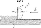
リード線5が第一電極2と接続されていて、リード線6が第二電極3と接続されている。ジェネレータ10からのRF出力はリード線5及び6を介してメス1と接続されていて、従ってほぼ一定のピーク電圧(一般に約400V)を有する無線周波数が第一電極2と第二電極3との間に出現するようになっている。図3において、メス1が組織7の対象部位に接触されると、RF電圧は一方の電極と組織表面との間でアークを発生する。第一電極2は、第二電極3と比較して断面積が小さく、かつ熱容量及び熱伝導率が小さいので、第一電極が活性電極の役割を果し、アークはこの第一電極から組織7へ発生する。電流は、組織7から第二電極3へ流れ、この第二電極が帰還電極の役割を果している。組織の切開が活性電極において生じる場合、メスが組織を通って移動する。メス1は組織7における切開に使用されてもよいし、あるいは組織層を除去するために、図3において矢印8の方向に横断的に移動されてもよい。 The lead wire 5 is connected to the
切開中に、活性電極2において多量の熱が発生され、電極の温度は100−250℃に上昇するかも知れない。しかしながら、絶縁体4の熱伝導率が小さいので、多量の熱が第二電極3へ伝達されることはない。熱が第二電極3に達した場合でも、銅材料の熱伝導率が大きいので、熱は電極表面から電極のボデー9の中へ伝導で除去される。このことは、第一電極2と第二電極3との間に温度差が保たれることを保証し、かつ第二電極3の温度を可能な限り長時間70°以下に維持することを保証するのに役立っている。このことは、器具12が作動されている場合はいつでも、第二電極3が帰還電極となっていることを保証し、かつ組織は第二電極3と固着しないことを保証している。 During the incision, a large amount of heat is generated at the
比較的低熱伝導率の絶縁体4を備えることに加えて、第一電極2を可能な限り絶縁体4に接触させないことを確実にすることが利点のあることである。図2において、第一電極2は絶縁体4と第二電極3とに連続的に取りつけられていなくて、一つ以上の点接触ピン11により取りつけられている。図4aは別の構造のメスを示めしていて、第一電極2は、その全長にわたって絶縁体4と断続的に接触するように形状化されていて、電極が絶縁体4から外向きに弓なりに曲がっている領域13を備えている。このことが、第一電極2から絶縁体4を通って第二電極3への熱の伝達を最小化するのに役立っている。図4bはさらに別の構造を示めしていて、第一電極2は、メッシュ形状となっている多数の穴15を備えている。このことが第一電極2から絶縁体4への熱の伝達を最小化している。図4cはもう一つの構造を示めしていて、第一電極2と絶縁体4との間に設置された波形電極層7を有している。このことは、第一電極2を発生された熱が第二電極3へ達することを防止していて、両者の間に温度差が維持されるようになっている。 In addition to providing the insulator 4 with relatively low thermal conductivity, it is advantageous to ensure that the
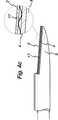
図4dは図2におけるメスの変形であって、メスがフック形状19となっている。第一電極2、第二電極3及び絶縁体4すべてがフック形状であって、装置の操作は図2を参照して説明したものとほぼ同様である。フック状電極は、特に組織を分離することに適切なものであって、RFなしの常温での切除器具として使用されるか、又はRF切開器具として使用される。処置あるいは切開にあたって、組織はフック19の角度20で保持することができる。 FIG. 4 d is a modification of the knife in FIG. 2, and the knife has a
いずれの電極の構造が採用されても、第一電極2から第二電極3へ通過してゆく熱が第二電極3の表面に接触している組織から伝達除去されることは利点のあることである。図2のメスにおいて、第二電極3は、電極の先端から熱を伝導で除去する比較的大質量の銅により構成されている。第二電極3の機能は、図5a及び5bに示めす冷却手段を採用することによりさらに強化されている。図5aにおいて、第二電極3はヒートパイプ27に取りつけられている。ヒートパイプ27は、閉じた中空パイプ28を備えていて、その中空チューブ28は、第二電極と隣接している末端部29と、器具12のハンドピース内部の基端部30とを有している。中空チューブ28は、アセトンあるいはアルコールのような沸騰温度の低い液体32の入っているキャビティ31を有している。使用時において、第二電極3からの熱は、チューブの末端部29において液体32を蒸発させ、この蒸気はチューブの基端部において凝縮する。というのは、基端部は末端部29に対して相対的に低温であるからである。このようにして、熱は第二電極3の末端部から基端部へ伝達され、そこから器具12のハンドピースを介して放散される。 Whichever electrode structure is adopted, it is advantageous that the heat passing from the
図5bは別の装置であって、図5aにおけるヒートパイプが強制冷却装置33に置き換えられている。冷却装置33は、チューブ34、末端部29及び基端部30を備えている。チューブ34が、内部ルーメン36と外部ルーメン37とを形成している同軸の内管35を含んでいる。内管35はチューブの末端部へ向けて穴があけられていて、従って内部ルーメン36と外部ルーメン37とはお互いに連通している。使用時において、自給式ポンプ(self-contained pump)38により、冷却流体39が内部ルーメン36から末端部29へ流れ、外部ルーメン37を介してもどり連続的に循環するようになっている。循環流体は第二電極3により加熱され、熱は流体によりチューブ34の基端部30へ送られる。このようにして、第一電極2における高温にもかかわらず、第二電極3は低温に維持される。 FIG. 5 b shows another device, in which the heat pipe in FIG. 5 a is replaced with a forced cooling device 33. The cooling device 33 includes a
残りの図は、組織7の凝固あるいは乾燥を行なうための、第三電極40を備えた装置を示めしている。図6aにおいて、メス1は図4bの構造にもとずいて示めされていて、類似の部品は同一符号が付番されている。第三電極40は、第一電極2と対向して第二電極3に取りつけられていて、さらに電気絶縁体41に取りつけられている。RF信号はジェネレータ10からリード線42を介して第三電極40へ供給することができる。絶縁体41は、シリコンラバーの薄い層か、又はポリマイド、PEEK若しくはPVC材料を含む別の材料の薄い層で作られている。薄い層により、熱がシリコンラバー層を通過することを保証され、かつ凝固用電極40が第二電極3の熱伝導の恩恵を受けることができることを保証されている。このようにして、第一電極2により発生された熱にもかかわらず、凝固用電極40は比較的低温に維持されている。使用にあたって、組織は前述したように切開される。切開の代りに凝固が所望される場合、第三電極40は組織7と接触して置かれ、凝固用RF信号が第二電極3と第三電極40との間に作用される。 The remaining figures show a device with a
図6bは別の実施形態を示めしていて、第二電極3及び第三電極40が窒化アルミニウム材料の基板43の上に金属化されたトラックとなっている。前述したように、この材料は電気的に絶縁されているけれど、良伝導体であって、熱が第二電極から第三電極へ熱を伝導することを可能にしている。 FIG. 6b shows another embodiment in which the
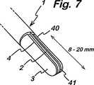
図7は、第一電極2が第二電極3と第三電極との間に設置されている装置を示めしている。第二及び第三電極3及び40の両者は、ほぼ半円形断面であって、ほぼ円柱体を形成していて、第一電極2が両者の中央領域から僅かに突出している。絶縁層4は第一電極2と第二電極3とを隔てていて、絶縁層41が第一電極2と第三電極40とを隔てている。使用者が器具で組織を切開する場合、ジェネレータ10は切開用RF信号を第一電極2と、第二及び第三電極3,40の一方又は両方との間に作用する。一方、使用者が組織を凝固する場合、ジェネレータ10は凝固用RF信号を第二電極3と第三電極40との間に作用する。第二及び第三電極30及び40の比較的広い表面積は、前述したように切開時において熱が伝導で逃げてゆくのと同じく、組織の効果的な凝固を可能にしている。 FIG. 7 shows an apparatus in which the
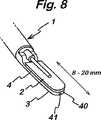
図8は別の構造を示めしていて、第二及び第三電極3及び40が並行して備えられている。第一電極2はほぼ平面であって、絶縁層4が、第一電極を器具の反対側における第二及び第三電極3及び40から隔てている。電極3及び40は、並行配列で配置されていて、間に絶縁層41がある。前述したように、器具は、第一電極2と、第二又は第三電極3又は40との間におけるRF信号を用いて組織を切開することができ、あるいは第二電極と第三電極との間におけるRF信号を用いて組織を凝固することができる。 FIG. 8 shows another structure in which the second and
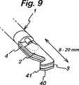
図9は別の実施形態を示めしていて、第一、第二及び第三電極が“サンドイッチ”配列に直列層として備えられている。第一電極2が図9における最上段層として、第三電極40が最下段層としてかつ第二電極3がそれらの間にはさまれて図示されている。絶縁層4及び41は、それぞれ第一、第二及び第三電極を隔てるようになっている。この配列がブレード1に対して比較的厚いエッジを提供していて、組織の凝固を容易なものとしている。 FIG. 9 shows another embodiment, where the first, second and third electrodes are provided as a series layer in a “sandwich” arrangement. The
図10は、サンドイッチ配列構造体と並行配列構造体との両者の特徴を利用している装置である。電極はサンドイッチ配列であって、図10において第一電極2は、図9に図示されているような最上段というよりはむしろ最下段に図示されている。第二電極3はサンドイッチの中段にあって、絶縁層4により第一電極から隔てられている。図10において、第三電極40は、最上段電極として図示されているけれど、中央凹部を有しており、その凹部を介して第二電極3の隆起部分50が突出している。第二及び第三電極は絶縁体41により隔てられていて、突起50の最上面は第三電極4の頂部と同一高さとなっている。図10に示めすようにこの配列は、メス1あるいは最上面のどちらかを組織の凝固に使用することができるようになっている。 FIG. 10 shows an apparatus that utilizes the characteristics of both the sandwich array structure and the parallel array structure. The electrodes have a sandwich arrangement, and in FIG. 10, the
図11は、メス1の端部が、両側面に絶縁層4及び41を備えた中央第一電極2を有している。絶縁層4及び41各々が、図51及び52それぞれに図示する傾斜したベベル末端部を有している。第二電極3は絶縁層4に取りつけられ、第二電極におけるベベル端部51は、メスの軸において第一電極2から軸方向にセットバックしている。同様に第三電極40が絶縁層41に取りつけられていて、第三電極におけるベベル端部52も第一電極2から軸方向にセットバックしている。ベベル端部51及び52は、第一電極と第二電極との間、及び第一電極と第三電極との間において0.25mmの最小間かく(図11において“X”で図示)を可能にしていて、メス1を全体としてスリムなプロフィールとしている。第一電極2は、第一及び第二絶縁層4及び41の端部から図11に図示するように僅かに突出していてもよい。前述したように、第一電極による熱伝達は、不連続的に絶縁層に取りつける、あるいは熱伝達を低減するために複数の穴をあける等の、種々の方法で低減されている。In FIG. 11, the end portion of the
本発明は、第一電極と第二電極との間の間隔、そこに作用される電圧、電極及び電気絶縁体として選択されたサイズと材料を含んでいる、多くのデザインパラメータの周到な選択によるものである。この周到な選択により、電極間における直接的なアークが発生しないこと、一つの電極だけが活性電極となること、そして帰還電極は低温維持されることとが保証されている。なおその低温維持は、帰還電極に到達する熱を防止することにより及び/又は熱をそこから除去し熱を第二電極へ伝達することにより行なわれている。 The present invention is based on careful selection of a number of design parameters, including the spacing between the first electrode and the second electrode, the voltage applied thereto, the size and material selected as the electrode and electrical insulator. Is. This careful selection ensures that no direct arcing occurs between the electrodes, that only one electrode becomes the active electrode, and that the return electrode is maintained at a low temperature. The low temperature is maintained by preventing heat reaching the return electrode and / or by removing heat from it and transferring the heat to the second electrode.
相対的に低温の帰還電極は、器具の帰還電極に隣接している組織において熱損傷が比較的小さいかあるいはなくて、一方組織が帰還電極から熱を伝導で除去することに役立っている。 The relatively cold return electrode has relatively little or no thermal damage in the tissue adjacent to the instrument return electrode, while the tissue helps remove heat from the return electrode by conduction.
Claims (21)
Translated fromJapanese該第一電極が該第二電極と異なる特性を有しており、該第一電極が活性電極になり、そして該第二電極が帰還電極となっており;
該第一及び第二電極間の離間距離は0.25mmと3.0mmとの間であって、該両電極が組織と接触して、該二極型切開用メスによる切開のために電圧が該第一電極と該第二電極との間に作用される場合、アークは該両電極間に直接的に発生しないようになっていて;組織を凝固するようになっている第三電極がさらに備えられていて、該第三電極はさらなる絶縁体により該第二電極から隔てられている二極切開用メスにおいて;
該第一、第二及び第三電極がサンドイッチ構造体の層となっていて、該第一電極が中央にあって、該電極各々の間に絶縁体の層があることと;
該第一電極が、該第二及び第三電極の外周縁から僅かに突出しており、そして該絶縁体の層各々の外周縁から僅かに突出していることとを特徴とする、二極型切開用メス。A bipolar incision knife comprising a first electrode and a second electrode, and an electrical insulator separating the electrodes;
It is wherein the first electrode have different characteristics and said second electrode, the said first electrode becomes active electrode, and the said second electrodehas a return electrode;
The distance between the first and second electrodes is between 0.25 mm and 3.0 mm so that both electrodes are in contact with tissue andno voltage is appliedfor incisionby the bipolar scalpel. when actingbetween saidfirst electrode and said second electrode, the arcis not so not directly generated between the both electrodes; a third electrode adapted to coagulate tissue further In abipolar scalpel provided, wherein the third electrode is separated from the second electrode by a further insulator;
The first, second and third electrodes are sandwiched layers, the first electrode is in the center, and there is an insulator layer between each of the electrodes;
Bipolar incision characterized in that thefirst electrode protrudes slightly from the outer periphery of the second and third electrodes and slightly protrudes from the outer periphery of each layer of the insulator For scalpel.
該二極型切開用メスが、請求項1−19のいずれか一項に記載の二極型切開用メスであり;The bipolar scalpel is the bipolar scalpel according to any one of claims 1-19;
該電気式外科手術用ジェネレータが、ほぼ一定のピーク電圧値を有する無線周波数電圧信号を該二極型切開用メスに供給するようになっている;電気式外科手術装置。The electrosurgical generator is adapted to supply a radio frequency voltage signal having a substantially constant peak voltage value to the bipolar scalpel; an electrosurgical device.
Applications Claiming Priority (4)
| Application Number | Priority Date | Filing Date | Title |
|---|---|---|---|
| GBGB0130975.6AGB0130975D0 (en) | 2001-12-27 | 2001-12-27 | A surgical instrument |
| GB0206207AGB0206207D0 (en) | 2002-03-15 | 2002-03-15 | A surgical instrument |
| GB0215402AGB0215402D0 (en) | 2002-07-03 | 2002-07-03 | A surgical instrument |
| PCT/GB2002/005893WO2003055402A1 (en) | 2001-12-27 | 2002-12-23 | A surgical instrument |
Publications (2)
| Publication Number | Publication Date |
|---|---|
| JP2005512726A JP2005512726A (en) | 2005-05-12 |
| JP4313205B2true JP4313205B2 (en) | 2009-08-12 |
Family
ID=27256366
Family Applications (1)
| Application Number | Title | Priority Date | Filing Date |
|---|---|---|---|
| JP2003555981AExpired - Fee RelatedJP4313205B2 (en) | 2001-12-27 | 2002-12-23 | Surgical instruments |
Country Status (5)
| Country | Link |
|---|---|
| EP (1) | EP1458300A1 (en) |
| JP (1) | JP4313205B2 (en) |
| CN (1) | CN100362969C (en) |
| AU (1) | AU2002358220B2 (en) |
| WO (1) | WO2003055402A1 (en) |
Families Citing this family (569)
| Publication number | Priority date | Publication date | Assignee | Title |
|---|---|---|---|---|
| GB0425842D0 (en) | 2004-11-24 | 2004-12-29 | Gyrus Group Plc | An electrosurgical instrument |
| EP2292151B1 (en) | 2002-05-10 | 2014-08-27 | Covidien LP | Surgical stapling apparatus having a wound closure material applicator assembly |
| JP4316491B2 (en) | 2002-05-10 | 2009-08-19 | タイコ ヘルスケア グループ エルピー | Wound closure material applicator and stapler |
| US9060770B2 (en) | 2003-05-20 | 2015-06-23 | Ethicon Endo-Surgery, Inc. | Robotically-driven surgical instrument with E-beam driver |
| US20070084897A1 (en) | 2003-05-20 | 2007-04-19 | Shelton Frederick E Iv | Articulating surgical stapling instrument incorporating a two-piece e-beam firing mechanism |
| GB2415140A (en) | 2004-06-18 | 2005-12-21 | Gyrus Medical Ltd | A surgical instrument |
| WO2005122935A1 (en)* | 2004-06-18 | 2005-12-29 | Olympus Corporation | Instrument for cutting organism tissue |
| DE102004031141A1 (en)* | 2004-06-28 | 2006-01-26 | Erbe Elektromedizin Gmbh | Electrosurgical instrument |
| US11998198B2 (en) | 2004-07-28 | 2024-06-04 | Cilag Gmbh International | Surgical stapling instrument incorporating a two-piece E-beam firing mechanism |
| US8215531B2 (en) | 2004-07-28 | 2012-07-10 | Ethicon Endo-Surgery, Inc. | Surgical stapling instrument having a medical substance dispenser |
| US9072535B2 (en) | 2011-05-27 | 2015-07-07 | Ethicon Endo-Surgery, Inc. | Surgical stapling instruments with rotatable staple deployment arrangements |
| US8905977B2 (en) | 2004-07-28 | 2014-12-09 | Ethicon Endo-Surgery, Inc. | Surgical stapling instrument having an electroactive polymer actuated medical substance dispenser |
| US11890012B2 (en) | 2004-07-28 | 2024-02-06 | Cilag Gmbh International | Staple cartridge comprising cartridge body and attached support |
| GB0425843D0 (en) | 2004-11-24 | 2004-12-29 | Gyrus Group Plc | An electrosurgical instrument |
| US8800838B2 (en) | 2005-08-31 | 2014-08-12 | Ethicon Endo-Surgery, Inc. | Robotically-controlled cable-based surgical end effectors |
| US11246590B2 (en) | 2005-08-31 | 2022-02-15 | Cilag Gmbh International | Staple cartridge including staple drivers having different unfired heights |
| US10159482B2 (en) | 2005-08-31 | 2018-12-25 | Ethicon Llc | Fastener cartridge assembly comprising a fixed anvil and different staple heights |
| US7934630B2 (en) | 2005-08-31 | 2011-05-03 | Ethicon Endo-Surgery, Inc. | Staple cartridges for forming staples having differing formed staple heights |
| US7669746B2 (en) | 2005-08-31 | 2010-03-02 | Ethicon Endo-Surgery, Inc. | Staple cartridges for forming staples having differing formed staple heights |
| US11484312B2 (en) | 2005-08-31 | 2022-11-01 | Cilag Gmbh International | Staple cartridge comprising a staple driver arrangement |
| US7673781B2 (en) | 2005-08-31 | 2010-03-09 | Ethicon Endo-Surgery, Inc. | Surgical stapling device with staple driver that supports multiple wire diameter staples |
| US9237891B2 (en) | 2005-08-31 | 2016-01-19 | Ethicon Endo-Surgery, Inc. | Robotically-controlled surgical stapling devices that produce formed staples having different lengths |
| US7607557B2 (en)† | 2005-11-04 | 2009-10-27 | Ethicon Endo-Surgery, Inc. | Surgical stapling instruments structured for pump-assisted delivery of medical agents |
| US20070106317A1 (en) | 2005-11-09 | 2007-05-10 | Shelton Frederick E Iv | Hydraulically and electrically actuated articulation joints for surgical instruments |
| US11224427B2 (en) | 2006-01-31 | 2022-01-18 | Cilag Gmbh International | Surgical stapling system including a console and retraction assembly |
| US8708213B2 (en) | 2006-01-31 | 2014-04-29 | Ethicon Endo-Surgery, Inc. | Surgical instrument having a feedback system |
| US8186555B2 (en) | 2006-01-31 | 2012-05-29 | Ethicon Endo-Surgery, Inc. | Motor-driven surgical cutting and fastening instrument with mechanical closure system |
| US9861359B2 (en) | 2006-01-31 | 2018-01-09 | Ethicon Llc | Powered surgical instruments with firing system lockout arrangements |
| US8763879B2 (en) | 2006-01-31 | 2014-07-01 | Ethicon Endo-Surgery, Inc. | Accessing data stored in a memory of surgical instrument |
| US11793518B2 (en) | 2006-01-31 | 2023-10-24 | Cilag Gmbh International | Powered surgical instruments with firing system lockout arrangements |
| US8820603B2 (en) | 2006-01-31 | 2014-09-02 | Ethicon Endo-Surgery, Inc. | Accessing data stored in a memory of a surgical instrument |
| US8161977B2 (en) | 2006-01-31 | 2012-04-24 | Ethicon Endo-Surgery, Inc. | Accessing data stored in a memory of a surgical instrument |
| US11278279B2 (en) | 2006-01-31 | 2022-03-22 | Cilag Gmbh International | Surgical instrument assembly |
| US20110295295A1 (en) | 2006-01-31 | 2011-12-01 | Ethicon Endo-Surgery, Inc. | Robotically-controlled surgical instrument having recording capabilities |
| US7753904B2 (en) | 2006-01-31 | 2010-07-13 | Ethicon Endo-Surgery, Inc. | Endoscopic surgical instrument with a handle that can articulate with respect to the shaft |
| US7845537B2 (en) | 2006-01-31 | 2010-12-07 | Ethicon Endo-Surgery, Inc. | Surgical instrument having recording capabilities |
| US20110024477A1 (en) | 2009-02-06 | 2011-02-03 | Hall Steven G | Driven Surgical Stapler Improvements |
| US20120292367A1 (en) | 2006-01-31 | 2012-11-22 | Ethicon Endo-Surgery, Inc. | Robotically-controlled end effector |
| US7854735B2 (en) | 2006-02-16 | 2010-12-21 | Ethicon Endo-Surgery, Inc. | Energy-based medical treatment system and method |
| US8236010B2 (en) | 2006-03-23 | 2012-08-07 | Ethicon Endo-Surgery, Inc. | Surgical fastener and cutter with mimicking end effector |
| US8992422B2 (en) | 2006-03-23 | 2015-03-31 | Ethicon Endo-Surgery, Inc. | Robotically-controlled endoscopic accessory channel |
| US8322455B2 (en) | 2006-06-27 | 2012-12-04 | Ethicon Endo-Surgery, Inc. | Manually driven surgical cutting and fastening instrument |
| US7740159B2 (en) | 2006-08-02 | 2010-06-22 | Ethicon Endo-Surgery, Inc. | Pneumatically powered surgical cutting and fastening instrument with a variable control of the actuating rate of firing with mechanical power assist |
| US10568652B2 (en) | 2006-09-29 | 2020-02-25 | Ethicon Llc | Surgical staples having attached drivers of different heights and stapling instruments for deploying the same |
| US20110087276A1 (en) | 2009-10-09 | 2011-04-14 | Ethicon Endo-Surgery, Inc. | Method for forming a staple |
| US7506791B2 (en) | 2006-09-29 | 2009-03-24 | Ethicon Endo-Surgery, Inc. | Surgical stapling instrument with mechanical mechanism for limiting maximum tissue compression |
| US10130359B2 (en) | 2006-09-29 | 2018-11-20 | Ethicon Llc | Method for forming a staple |
| US11980366B2 (en) | 2006-10-03 | 2024-05-14 | Cilag Gmbh International | Surgical instrument |
| US8459520B2 (en) | 2007-01-10 | 2013-06-11 | Ethicon Endo-Surgery, Inc. | Surgical instrument with wireless communication between control unit and remote sensor |
| US11291441B2 (en) | 2007-01-10 | 2022-04-05 | Cilag Gmbh International | Surgical instrument with wireless communication between control unit and remote sensor |
| US8684253B2 (en) | 2007-01-10 | 2014-04-01 | Ethicon Endo-Surgery, Inc. | Surgical instrument with wireless communication between a control unit of a robotic system and remote sensor |
| US8652120B2 (en) | 2007-01-10 | 2014-02-18 | Ethicon Endo-Surgery, Inc. | Surgical instrument with wireless communication between control unit and sensor transponders |
| US8632535B2 (en) | 2007-01-10 | 2014-01-21 | Ethicon Endo-Surgery, Inc. | Interlock and surgical instrument including same |
| US20080169333A1 (en) | 2007-01-11 | 2008-07-17 | Shelton Frederick E | Surgical stapler end effector with tapered distal end |
| US11039836B2 (en) | 2007-01-11 | 2021-06-22 | Cilag Gmbh International | Staple cartridge for use with a surgical stapling instrument |
| US7673782B2 (en) | 2007-03-15 | 2010-03-09 | Ethicon Endo-Surgery, Inc. | Surgical stapling instrument having a releasable buttress material |
| US8893946B2 (en) | 2007-03-28 | 2014-11-25 | Ethicon Endo-Surgery, Inc. | Laparoscopic tissue thickness and clamp load measuring devices |
| US8157145B2 (en) | 2007-05-31 | 2012-04-17 | Ethicon Endo-Surgery, Inc. | Pneumatically powered surgical cutting and fastening instrument with electrical feedback |
| US8534528B2 (en) | 2007-06-04 | 2013-09-17 | Ethicon Endo-Surgery, Inc. | Surgical instrument having a multiple rate directional switching mechanism |
| US7905380B2 (en) | 2007-06-04 | 2011-03-15 | Ethicon Endo-Surgery, Inc. | Surgical instrument having a multiple rate directional switching mechanism |
| US7832408B2 (en) | 2007-06-04 | 2010-11-16 | Ethicon Endo-Surgery, Inc. | Surgical instrument having a directional switching mechanism |
| US8931682B2 (en) | 2007-06-04 | 2015-01-13 | Ethicon Endo-Surgery, Inc. | Robotically-controlled shaft based rotary drive systems for surgical instruments |
| US11564682B2 (en) | 2007-06-04 | 2023-01-31 | Cilag Gmbh International | Surgical stapler device |
| US8408439B2 (en) | 2007-06-22 | 2013-04-02 | Ethicon Endo-Surgery, Inc. | Surgical stapling instrument with an articulatable end effector |
| US7753245B2 (en) | 2007-06-22 | 2010-07-13 | Ethicon Endo-Surgery, Inc. | Surgical stapling instruments |
| US11849941B2 (en) | 2007-06-29 | 2023-12-26 | Cilag Gmbh International | Staple cartridge having staple cavities extending at a transverse angle relative to a longitudinal cartridge axis |
| US7766209B2 (en) | 2008-02-13 | 2010-08-03 | Ethicon Endo-Surgery, Inc. | Surgical stapling instrument with improved firing trigger arrangement |
| US8561870B2 (en) | 2008-02-13 | 2013-10-22 | Ethicon Endo-Surgery, Inc. | Surgical stapling instrument |
| US8453908B2 (en) | 2008-02-13 | 2013-06-04 | Ethicon Endo-Surgery, Inc. | Surgical stapling instrument with improved firing trigger arrangement |
| US8540133B2 (en) | 2008-09-19 | 2013-09-24 | Ethicon Endo-Surgery, Inc. | Staple cartridge |
| US7866527B2 (en) | 2008-02-14 | 2011-01-11 | Ethicon Endo-Surgery, Inc. | Surgical stapling apparatus with interlockable firing system |
| US9179912B2 (en) | 2008-02-14 | 2015-11-10 | Ethicon Endo-Surgery, Inc. | Robotically-controlled motorized surgical cutting and fastening instrument |
| US8622274B2 (en) | 2008-02-14 | 2014-01-07 | Ethicon Endo-Surgery, Inc. | Motorized cutting and fastening instrument having control circuit for optimizing battery usage |
| US8459525B2 (en) | 2008-02-14 | 2013-06-11 | Ethicon Endo-Sugery, Inc. | Motorized surgical cutting and fastening instrument having a magnetic drive train torque limiting device |
| US8758391B2 (en) | 2008-02-14 | 2014-06-24 | Ethicon Endo-Surgery, Inc. | Interchangeable tools for surgical instruments |
| JP5410110B2 (en) | 2008-02-14 | 2014-02-05 | エシコン・エンド−サージェリィ・インコーポレイテッド | Surgical cutting / fixing instrument with RF electrode |
| US7793812B2 (en) | 2008-02-14 | 2010-09-14 | Ethicon Endo-Surgery, Inc. | Disposable motor-driven loading unit for use with a surgical cutting and stapling apparatus |
| US7819298B2 (en) | 2008-02-14 | 2010-10-26 | Ethicon Endo-Surgery, Inc. | Surgical stapling apparatus with control features operable with one hand |
| US8584919B2 (en) | 2008-02-14 | 2013-11-19 | Ethicon Endo-Sugery, Inc. | Surgical stapling apparatus with load-sensitive firing mechanism |
| US8573465B2 (en) | 2008-02-14 | 2013-11-05 | Ethicon Endo-Surgery, Inc. | Robotically-controlled surgical end effector system with rotary actuated closure systems |
| US8752749B2 (en) | 2008-02-14 | 2014-06-17 | Ethicon Endo-Surgery, Inc. | Robotically-controlled disposable motor-driven loading unit |
| US8657174B2 (en) | 2008-02-14 | 2014-02-25 | Ethicon Endo-Surgery, Inc. | Motorized surgical cutting and fastening instrument having handle based power source |
| US8636736B2 (en) | 2008-02-14 | 2014-01-28 | Ethicon Endo-Surgery, Inc. | Motorized surgical cutting and fastening instrument |
| US11986183B2 (en) | 2008-02-14 | 2024-05-21 | Cilag Gmbh International | Surgical cutting and fastening instrument comprising a plurality of sensors to measure an electrical parameter |
| US20090206141A1 (en) | 2008-02-15 | 2009-08-20 | Ethicon Endo-Surgery, Inc. | Buttress material having an activatable adhesive |
| US9585657B2 (en) | 2008-02-15 | 2017-03-07 | Ethicon Endo-Surgery, Llc | Actuator for releasing a layer of material from a surgical end effector |
| US8608044B2 (en) | 2008-02-15 | 2013-12-17 | Ethicon Endo-Surgery, Inc. | Feedback and lockout mechanism for surgical instrument |
| US20090206131A1 (en) | 2008-02-15 | 2009-08-20 | Ethicon Endo-Surgery, Inc. | End effector coupling arrangements for a surgical cutting and stapling instrument |
| US11272927B2 (en) | 2008-02-15 | 2022-03-15 | Cilag Gmbh International | Layer arrangements for surgical staple cartridges |
| US8083120B2 (en) | 2008-09-18 | 2011-12-27 | Ethicon Endo-Surgery, Inc. | End effector for use with a surgical cutting and stapling instrument |
| PL3476312T3 (en) | 2008-09-19 | 2024-03-11 | Ethicon Llc | Surgical stapler with apparatus for adjusting staple height |
| US7954686B2 (en) | 2008-09-19 | 2011-06-07 | Ethicon Endo-Surgery, Inc. | Surgical stapler with apparatus for adjusting staple height |
| US9050083B2 (en) | 2008-09-23 | 2015-06-09 | Ethicon Endo-Surgery, Inc. | Motorized surgical instrument |
| US9005230B2 (en) | 2008-09-23 | 2015-04-14 | Ethicon Endo-Surgery, Inc. | Motorized surgical instrument |
| US9386983B2 (en) | 2008-09-23 | 2016-07-12 | Ethicon Endo-Surgery, Llc | Robotically-controlled motorized surgical instrument |
| US11648005B2 (en) | 2008-09-23 | 2023-05-16 | Cilag Gmbh International | Robotically-controlled motorized surgical instrument with an end effector |
| US8210411B2 (en) | 2008-09-23 | 2012-07-03 | Ethicon Endo-Surgery, Inc. | Motor-driven surgical cutting instrument |
| US8608045B2 (en) | 2008-10-10 | 2013-12-17 | Ethicon Endo-Sugery, Inc. | Powered surgical cutting and stapling apparatus with manually retractable firing system |
| US8485413B2 (en) | 2009-02-05 | 2013-07-16 | Ethicon Endo-Surgery, Inc. | Surgical stapling instrument comprising an articulation joint |
| US8517239B2 (en) | 2009-02-05 | 2013-08-27 | Ethicon Endo-Surgery, Inc. | Surgical stapling instrument comprising a magnetic element driver |
| US8397971B2 (en) | 2009-02-05 | 2013-03-19 | Ethicon Endo-Surgery, Inc. | Sterilizable surgical instrument |
| US8414577B2 (en) | 2009-02-05 | 2013-04-09 | Ethicon Endo-Surgery, Inc. | Surgical instruments and components for use in sterile environments |
| RU2525225C2 (en) | 2009-02-06 | 2014-08-10 | Этикон Эндо-Серджери, Инк. | Improvement of drive surgical suturing instrument |
| US8453907B2 (en) | 2009-02-06 | 2013-06-04 | Ethicon Endo-Surgery, Inc. | Motor driven surgical fastener device with cutting member reversing mechanism |
| US8444036B2 (en) | 2009-02-06 | 2013-05-21 | Ethicon Endo-Surgery, Inc. | Motor driven surgical fastener device with mechanisms for adjusting a tissue gap within the end effector |
| US8066167B2 (en) | 2009-03-23 | 2011-11-29 | Ethicon Endo-Surgery, Inc. | Circular surgical stapling instrument with anvil locking system |
| US20110114697A1 (en) | 2009-11-19 | 2011-05-19 | Ethicon Endo-Surgery, Inc. | Circular stapler introducer with multi-lumen sheath |
| US8136712B2 (en) | 2009-12-10 | 2012-03-20 | Ethicon Endo-Surgery, Inc. | Surgical stapler with discrete staple height adjustment and tactile feedback |
| US8220688B2 (en) | 2009-12-24 | 2012-07-17 | Ethicon Endo-Surgery, Inc. | Motor-driven surgical cutting instrument with electric actuator directional control assembly |
| US8851354B2 (en) | 2009-12-24 | 2014-10-07 | Ethicon Endo-Surgery, Inc. | Surgical cutting instrument that analyzes tissue thickness |
| US8267300B2 (en) | 2009-12-30 | 2012-09-18 | Ethicon Endo-Surgery, Inc. | Dampening device for endoscopic surgical stapler |
| US8608046B2 (en) | 2010-01-07 | 2013-12-17 | Ethicon Endo-Surgery, Inc. | Test device for a surgical tool |
| US8801734B2 (en) | 2010-07-30 | 2014-08-12 | Ethicon Endo-Surgery, Inc. | Circular stapling instruments with secondary cutting arrangements and methods of using same |
| US8789740B2 (en) | 2010-07-30 | 2014-07-29 | Ethicon Endo-Surgery, Inc. | Linear cutting and stapling device with selectively disengageable cutting member |
| US8783543B2 (en) | 2010-07-30 | 2014-07-22 | Ethicon Endo-Surgery, Inc. | Tissue acquisition arrangements and methods for surgical stapling devices |
| US8360296B2 (en) | 2010-09-09 | 2013-01-29 | Ethicon Endo-Surgery, Inc. | Surgical stapling head assembly with firing lockout for a surgical stapler |
| US9289212B2 (en) | 2010-09-17 | 2016-03-22 | Ethicon Endo-Surgery, Inc. | Surgical instruments and batteries for surgical instruments |
| US8632525B2 (en) | 2010-09-17 | 2014-01-21 | Ethicon Endo-Surgery, Inc. | Power control arrangements for surgical instruments and batteries |
| US20120078244A1 (en) | 2010-09-24 | 2012-03-29 | Worrell Barry C | Control features for articulating surgical device |
| US8733613B2 (en) | 2010-09-29 | 2014-05-27 | Ethicon Endo-Surgery, Inc. | Staple cartridge |
| US11925354B2 (en) | 2010-09-30 | 2024-03-12 | Cilag Gmbh International | Staple cartridge comprising staples positioned within a compressible portion thereof |
| US12213666B2 (en) | 2010-09-30 | 2025-02-04 | Cilag Gmbh International | Tissue thickness compensator comprising layers |
| US9301753B2 (en) | 2010-09-30 | 2016-04-05 | Ethicon Endo-Surgery, Llc | Expandable tissue thickness compensator |
| US9232941B2 (en) | 2010-09-30 | 2016-01-12 | Ethicon Endo-Surgery, Inc. | Tissue thickness compensator comprising a reservoir |
| US9307989B2 (en) | 2012-03-28 | 2016-04-12 | Ethicon Endo-Surgery, Llc | Tissue stapler having a thickness compensator incorportating a hydrophobic agent |
| US11298125B2 (en) | 2010-09-30 | 2022-04-12 | Cilag Gmbh International | Tissue stapler having a thickness compensator |
| US9314246B2 (en) | 2010-09-30 | 2016-04-19 | Ethicon Endo-Surgery, Llc | Tissue stapler having a thickness compensator incorporating an anti-inflammatory agent |
| US9629814B2 (en) | 2010-09-30 | 2017-04-25 | Ethicon Endo-Surgery, Llc | Tissue thickness compensator configured to redistribute compressive forces |
| US9364233B2 (en) | 2010-09-30 | 2016-06-14 | Ethicon Endo-Surgery, Llc | Tissue thickness compensators for circular surgical staplers |
| US9386988B2 (en) | 2010-09-30 | 2016-07-12 | Ethicon End-Surgery, LLC | Retainer assembly including a tissue thickness compensator |
| US9332974B2 (en) | 2010-09-30 | 2016-05-10 | Ethicon Endo-Surgery, Llc | Layered tissue thickness compensator |
| US10945731B2 (en) | 2010-09-30 | 2021-03-16 | Ethicon Llc | Tissue thickness compensator comprising controlled release and expansion |
| US8893949B2 (en) | 2010-09-30 | 2014-11-25 | Ethicon Endo-Surgery, Inc. | Surgical stapler with floating anvil |
| US11812965B2 (en) | 2010-09-30 | 2023-11-14 | Cilag Gmbh International | Layer of material for a surgical end effector |
| RU2013119928A (en) | 2010-09-30 | 2014-11-10 | Этикон Эндо-Серджери, Инк. | A STAPLING SYSTEM CONTAINING A RETAINING MATRIX AND A LEVELING MATRIX |
| US9113862B2 (en) | 2010-09-30 | 2015-08-25 | Ethicon Endo-Surgery, Inc. | Surgical stapling instrument with a variable staple forming system |
| US9788834B2 (en) | 2010-09-30 | 2017-10-17 | Ethicon Llc | Layer comprising deployable attachment members |
| US9301752B2 (en) | 2010-09-30 | 2016-04-05 | Ethicon Endo-Surgery, Llc | Tissue thickness compensator comprising a plurality of capsules |
| US9220501B2 (en) | 2010-09-30 | 2015-12-29 | Ethicon Endo-Surgery, Inc. | Tissue thickness compensators |
| US9351730B2 (en) | 2011-04-29 | 2016-05-31 | Ethicon Endo-Surgery, Llc | Tissue thickness compensator comprising channels |
| US9277919B2 (en) | 2010-09-30 | 2016-03-08 | Ethicon Endo-Surgery, Llc | Tissue thickness compensator comprising fibers to produce a resilient load |
| US9055941B2 (en) | 2011-09-23 | 2015-06-16 | Ethicon Endo-Surgery, Inc. | Staple cartridge including collapsible deck |
| US9016542B2 (en) | 2010-09-30 | 2015-04-28 | Ethicon Endo-Surgery, Inc. | Staple cartridge comprising compressible distortion resistant components |
| USD650074S1 (en) | 2010-10-01 | 2011-12-06 | Ethicon Endo-Surgery, Inc. | Surgical instrument |
| US8695866B2 (en) | 2010-10-01 | 2014-04-15 | Ethicon Endo-Surgery, Inc. | Surgical instrument having a power control circuit |
| CN103200892B (en)* | 2010-10-20 | 2015-08-26 | 泰尔茂心血管系统公司 | Surgical instrument |
| GB2487199A (en) | 2011-01-11 | 2012-07-18 | Creo Medical Ltd | Electrosurgical device with fluid conduit |
| US9168082B2 (en)* | 2011-02-09 | 2015-10-27 | Arthrocare Corporation | Fine dissection electrosurgical device |
| US9211122B2 (en) | 2011-03-14 | 2015-12-15 | Ethicon Endo-Surgery, Inc. | Surgical access devices with anvil introduction and specimen retrieval structures |
| US8540131B2 (en) | 2011-03-15 | 2013-09-24 | Ethicon Endo-Surgery, Inc. | Surgical staple cartridges with tissue tethers for manipulating divided tissue and methods of using same |
| US9044229B2 (en) | 2011-03-15 | 2015-06-02 | Ethicon Endo-Surgery, Inc. | Surgical fastener instruments |
| US8800841B2 (en) | 2011-03-15 | 2014-08-12 | Ethicon Endo-Surgery, Inc. | Surgical staple cartridges |
| US8926598B2 (en) | 2011-03-15 | 2015-01-06 | Ethicon Endo-Surgery, Inc. | Surgical instruments with articulatable and rotatable end effector |
| US8857693B2 (en) | 2011-03-15 | 2014-10-14 | Ethicon Endo-Surgery, Inc. | Surgical instruments with lockable articulating end effector |
| AU2012250197B2 (en) | 2011-04-29 | 2017-08-10 | Ethicon Endo-Surgery, Inc. | Staple cartridge comprising staples positioned within a compressible portion thereof |
| US11207064B2 (en) | 2011-05-27 | 2021-12-28 | Cilag Gmbh International | Automated end effector component reloading system for use with a robotic system |
| US8833632B2 (en) | 2011-09-06 | 2014-09-16 | Ethicon Endo-Surgery, Inc. | Firing member displacement system for a stapling instrument |
| US9050084B2 (en) | 2011-09-23 | 2015-06-09 | Ethicon Endo-Surgery, Inc. | Staple cartridge including collapsible deck arrangement |
| US9693816B2 (en)* | 2012-01-30 | 2017-07-04 | Covidien Lp | Electrosurgical apparatus with integrated energy sensing at tissue site |
| US9044230B2 (en) | 2012-02-13 | 2015-06-02 | Ethicon Endo-Surgery, Inc. | Surgical cutting and fastening instrument with apparatus for determining cartridge and firing motion status |
| US9078653B2 (en) | 2012-03-26 | 2015-07-14 | Ethicon Endo-Surgery, Inc. | Surgical stapling device with lockout system for preventing actuation in the absence of an installed staple cartridge |
| MX358135B (en) | 2012-03-28 | 2018-08-06 | Ethicon Endo Surgery Inc | Tissue thickness compensator comprising a plurality of layers. |
| BR112014024098B1 (en) | 2012-03-28 | 2021-05-25 | Ethicon Endo-Surgery, Inc. | staple cartridge |
| JP6224070B2 (en) | 2012-03-28 | 2017-11-01 | エシコン・エンド−サージェリィ・インコーポレイテッドEthicon Endo−Surgery,Inc. | Retainer assembly including tissue thickness compensator |
| US9198662B2 (en) | 2012-03-28 | 2015-12-01 | Ethicon Endo-Surgery, Inc. | Tissue thickness compensator having improved visibility |
| US9101358B2 (en) | 2012-06-15 | 2015-08-11 | Ethicon Endo-Surgery, Inc. | Articulatable surgical instrument comprising a firing drive |
| US9028494B2 (en) | 2012-06-28 | 2015-05-12 | Ethicon Endo-Surgery, Inc. | Interchangeable end effector coupling arrangement |
| BR112014032776B1 (en) | 2012-06-28 | 2021-09-08 | Ethicon Endo-Surgery, Inc | SURGICAL INSTRUMENT SYSTEM AND SURGICAL KIT FOR USE WITH A SURGICAL INSTRUMENT SYSTEM |
| US9561038B2 (en) | 2012-06-28 | 2017-02-07 | Ethicon Endo-Surgery, Llc | Interchangeable clip applier |
| US9125662B2 (en) | 2012-06-28 | 2015-09-08 | Ethicon Endo-Surgery, Inc. | Multi-axis articulating and rotating surgical tools |
| US11278284B2 (en) | 2012-06-28 | 2022-03-22 | Cilag Gmbh International | Rotary drive arrangements for surgical instruments |
| US9408606B2 (en) | 2012-06-28 | 2016-08-09 | Ethicon Endo-Surgery, Llc | Robotically powered surgical device with manually-actuatable reversing system |
| US9101385B2 (en) | 2012-06-28 | 2015-08-11 | Ethicon Endo-Surgery, Inc. | Electrode connections for rotary driven surgical tools |
| US20140005718A1 (en) | 2012-06-28 | 2014-01-02 | Ethicon Endo-Surgery, Inc. | Multi-functional powered surgical device with external dissection features |
| US20140001231A1 (en) | 2012-06-28 | 2014-01-02 | Ethicon Endo-Surgery, Inc. | Firing system lockout arrangements for surgical instruments |
| US9119657B2 (en) | 2012-06-28 | 2015-09-01 | Ethicon Endo-Surgery, Inc. | Rotary actuatable closure arrangement for surgical end effector |
| US9072536B2 (en) | 2012-06-28 | 2015-07-07 | Ethicon Endo-Surgery, Inc. | Differential locking arrangements for rotary powered surgical instruments |
| US9289256B2 (en) | 2012-06-28 | 2016-03-22 | Ethicon Endo-Surgery, Llc | Surgical end effectors having angled tissue-contacting surfaces |
| US9282974B2 (en) | 2012-06-28 | 2016-03-15 | Ethicon Endo-Surgery, Llc | Empty clip cartridge lockout |
| US12383267B2 (en) | 2012-06-28 | 2025-08-12 | Cilag Gmbh International | Robotically powered surgical device with manually-actuatable reversing system |
| JP6290201B2 (en) | 2012-06-28 | 2018-03-07 | エシコン・エンド−サージェリィ・インコーポレイテッドEthicon Endo−Surgery,Inc. | Lockout for empty clip cartridge |
| US8747238B2 (en) | 2012-06-28 | 2014-06-10 | Ethicon Endo-Surgery, Inc. | Rotary drive shaft assemblies for surgical instruments with articulatable end effectors |
| GB2503673A (en) | 2012-07-03 | 2014-01-08 | Creo Medical Ltd | Electrosurgical device with convex under surface |
| US9649146B2 (en) | 2012-10-02 | 2017-05-16 | Covidien Lp | Electro-thermal device |
| US9386985B2 (en) | 2012-10-15 | 2016-07-12 | Ethicon Endo-Surgery, Llc | Surgical cutting instrument |
| US9386984B2 (en) | 2013-02-08 | 2016-07-12 | Ethicon Endo-Surgery, Llc | Staple cartridge comprising a releasable cover |
| US10092292B2 (en) | 2013-02-28 | 2018-10-09 | Ethicon Llc | Staple forming features for surgical stapling instrument |
| US9468438B2 (en) | 2013-03-01 | 2016-10-18 | Eticon Endo-Surgery, LLC | Sensor straightened end effector during removal through trocar |
| RU2672520C2 (en) | 2013-03-01 | 2018-11-15 | Этикон Эндо-Серджери, Инк. | Hingedly turnable surgical instruments with conducting ways for signal transfer |
| BR112015021082B1 (en) | 2013-03-01 | 2022-05-10 | Ethicon Endo-Surgery, Inc | surgical instrument |
| US9345481B2 (en) | 2013-03-13 | 2016-05-24 | Ethicon Endo-Surgery, Llc | Staple cartridge tissue thickness sensor system |
| US9629629B2 (en) | 2013-03-14 | 2017-04-25 | Ethicon Endo-Surgey, LLC | Control systems for surgical instruments |
| US9808244B2 (en) | 2013-03-14 | 2017-11-07 | Ethicon Llc | Sensor arrangements for absolute positioning system for surgical instruments |
| US9795384B2 (en) | 2013-03-27 | 2017-10-24 | Ethicon Llc | Fastener cartridge comprising a tissue thickness compensator and a gap setting element |
| US9332984B2 (en) | 2013-03-27 | 2016-05-10 | Ethicon Endo-Surgery, Llc | Fastener cartridge assemblies |
| US9572577B2 (en) | 2013-03-27 | 2017-02-21 | Ethicon Endo-Surgery, Llc | Fastener cartridge comprising a tissue thickness compensator including openings therein |
| BR112015026109B1 (en) | 2013-04-16 | 2022-02-22 | Ethicon Endo-Surgery, Inc | surgical instrument |
| US9826976B2 (en) | 2013-04-16 | 2017-11-28 | Ethicon Llc | Motor driven surgical instruments with lockable dual drive shafts |
| US9574644B2 (en) | 2013-05-30 | 2017-02-21 | Ethicon Endo-Surgery, Llc | Power module for use with a surgical instrument |
| WO2015022842A1 (en)* | 2013-08-16 | 2015-02-19 | 住友ベークライト株式会社 | High-frequency treatment instrument |
| MX369362B (en) | 2013-08-23 | 2019-11-06 | Ethicon Endo Surgery Llc | Firing member retraction devices for powered surgical instruments. |
| US9775609B2 (en) | 2013-08-23 | 2017-10-03 | Ethicon Llc | Tamper proof circuit for surgical instrument battery pack |
| US20140171986A1 (en) | 2013-09-13 | 2014-06-19 | Ethicon Endo-Surgery, Inc. | Surgical Clip Having Comliant Portion |
| US9839428B2 (en) | 2013-12-23 | 2017-12-12 | Ethicon Llc | Surgical cutting and stapling instruments with independent jaw control features |
| US9681870B2 (en) | 2013-12-23 | 2017-06-20 | Ethicon Llc | Articulatable surgical instruments with separate and distinct closing and firing systems |
| US9642620B2 (en) | 2013-12-23 | 2017-05-09 | Ethicon Endo-Surgery, Llc | Surgical cutting and stapling instruments with articulatable end effectors |
| US20150173749A1 (en) | 2013-12-23 | 2015-06-25 | Ethicon Endo-Surgery, Inc. | Surgical staples and staple cartridges |
| US20150173756A1 (en) | 2013-12-23 | 2015-06-25 | Ethicon Endo-Surgery, Inc. | Surgical cutting and stapling methods |
| US9724092B2 (en) | 2013-12-23 | 2017-08-08 | Ethicon Llc | Modular surgical instruments |
| GB201323171D0 (en)* | 2013-12-31 | 2014-02-12 | Creo Medical Ltd | Electrosurgical apparatus and device |
| US9962161B2 (en) | 2014-02-12 | 2018-05-08 | Ethicon Llc | Deliverable surgical instrument |
| US20140166724A1 (en) | 2014-02-24 | 2014-06-19 | Ethicon Endo-Surgery, Inc. | Staple cartridge including a barbed staple |
| JP6462004B2 (en) | 2014-02-24 | 2019-01-30 | エシコン エルエルシー | Fastening system with launcher lockout |
| US10004497B2 (en) | 2014-03-26 | 2018-06-26 | Ethicon Llc | Interface systems for use with surgical instruments |
| US9913642B2 (en) | 2014-03-26 | 2018-03-13 | Ethicon Llc | Surgical instrument comprising a sensor system |
| US20150272580A1 (en) | 2014-03-26 | 2015-10-01 | Ethicon Endo-Surgery, Inc. | Verification of number of battery exchanges/procedure count |
| US12232723B2 (en) | 2014-03-26 | 2025-02-25 | Cilag Gmbh International | Systems and methods for controlling a segmented circuit |
| US10013049B2 (en) | 2014-03-26 | 2018-07-03 | Ethicon Llc | Power management through sleep options of segmented circuit and wake up control |
| BR112016021943B1 (en) | 2014-03-26 | 2022-06-14 | Ethicon Endo-Surgery, Llc | SURGICAL INSTRUMENT FOR USE BY AN OPERATOR IN A SURGICAL PROCEDURE |
| BR112016023825B1 (en) | 2014-04-16 | 2022-08-02 | Ethicon Endo-Surgery, Llc | STAPLE CARTRIDGE FOR USE WITH A SURGICAL STAPLER AND STAPLE CARTRIDGE FOR USE WITH A SURGICAL INSTRUMENT |
| US20150297225A1 (en) | 2014-04-16 | 2015-10-22 | Ethicon Endo-Surgery, Inc. | Fastener cartridges including extensions having different configurations |
| US10327764B2 (en) | 2014-09-26 | 2019-06-25 | Ethicon Llc | Method for creating a flexible staple line |
| CN106456176B (en) | 2014-04-16 | 2019-06-28 | 伊西康内外科有限责任公司 | Fastener Cartridge Including Extensions With Different Configurations |
| CN106456159B (en) | 2014-04-16 | 2019-03-08 | 伊西康内外科有限责任公司 | Fastener Cartridge Assembly and Nail Retainer Cover Arrangement |
| US10470768B2 (en) | 2014-04-16 | 2019-11-12 | Ethicon Llc | Fastener cartridge including a layer attached thereto |
| US10045781B2 (en) | 2014-06-13 | 2018-08-14 | Ethicon Llc | Closure lockout systems for surgical instruments |
| US10135242B2 (en) | 2014-09-05 | 2018-11-20 | Ethicon Llc | Smart cartridge wake up operation and data retention |
| BR112017004361B1 (en) | 2014-09-05 | 2023-04-11 | Ethicon Llc | ELECTRONIC SYSTEM FOR A SURGICAL INSTRUMENT |
| US11311294B2 (en) | 2014-09-05 | 2022-04-26 | Cilag Gmbh International | Powered medical device including measurement of closure state of jaws |
| US10105142B2 (en) | 2014-09-18 | 2018-10-23 | Ethicon Llc | Surgical stapler with plurality of cutting elements |
| US11523821B2 (en) | 2014-09-26 | 2022-12-13 | Cilag Gmbh International | Method for creating a flexible staple line |
| CN107427300B (en) | 2014-09-26 | 2020-12-04 | 伊西康有限责任公司 | Surgical suture buttresses and auxiliary materials |
| US10076325B2 (en) | 2014-10-13 | 2018-09-18 | Ethicon Llc | Surgical stapling apparatus comprising a tissue stop |
| US9924944B2 (en) | 2014-10-16 | 2018-03-27 | Ethicon Llc | Staple cartridge comprising an adjunct material |
| US10517594B2 (en) | 2014-10-29 | 2019-12-31 | Ethicon Llc | Cartridge assemblies for surgical staplers |
| US11141153B2 (en) | 2014-10-29 | 2021-10-12 | Cilag Gmbh International | Staple cartridges comprising driver arrangements |
| US9844376B2 (en) | 2014-11-06 | 2017-12-19 | Ethicon Llc | Staple cartridge comprising a releasable adjunct material |
| US10736636B2 (en) | 2014-12-10 | 2020-08-11 | Ethicon Llc | Articulatable surgical instrument system |
| US10085748B2 (en) | 2014-12-18 | 2018-10-02 | Ethicon Llc | Locking arrangements for detachable shaft assemblies with articulatable surgical end effectors |
| US10188385B2 (en) | 2014-12-18 | 2019-01-29 | Ethicon Llc | Surgical instrument system comprising lockable systems |
| US9943309B2 (en) | 2014-12-18 | 2018-04-17 | Ethicon Llc | Surgical instruments with articulatable end effectors and movable firing beam support arrangements |
| US9844375B2 (en) | 2014-12-18 | 2017-12-19 | Ethicon Llc | Drive arrangements for articulatable surgical instruments |
| MX389118B (en) | 2014-12-18 | 2025-03-20 | Ethicon Llc | SURGICAL INSTRUMENT WITH AN ANVIL THAT CAN BE SELECTIVELY MOVED ON A DISCRETE, NON-MOBILE AXIS RELATIVE TO A STAPLE CARTRIDGE. |
| US10117649B2 (en) | 2014-12-18 | 2018-11-06 | Ethicon Llc | Surgical instrument assembly comprising a lockable articulation system |
| US9987000B2 (en) | 2014-12-18 | 2018-06-05 | Ethicon Llc | Surgical instrument assembly comprising a flexible articulation system |
| US9844374B2 (en) | 2014-12-18 | 2017-12-19 | Ethicon Llc | Surgical instrument systems comprising an articulatable end effector and means for adjusting the firing stroke of a firing member |
| BR112017014919A2 (en)* | 2015-01-13 | 2018-01-09 | Megadyne Med Prod Inc | precision tapered blade electrosurgical instrument |
| US11154301B2 (en) | 2015-02-27 | 2021-10-26 | Cilag Gmbh International | Modular stapling assembly |
| US10180463B2 (en) | 2015-02-27 | 2019-01-15 | Ethicon Llc | Surgical apparatus configured to assess whether a performance parameter of the surgical apparatus is within an acceptable performance band |
| US10159483B2 (en) | 2015-02-27 | 2018-12-25 | Ethicon Llc | Surgical apparatus configured to track an end-of-life parameter |
| US9993258B2 (en) | 2015-02-27 | 2018-06-12 | Ethicon Llc | Adaptable surgical instrument handle |
| US10245033B2 (en) | 2015-03-06 | 2019-04-02 | Ethicon Llc | Surgical instrument comprising a lockable battery housing |
| US10548504B2 (en) | 2015-03-06 | 2020-02-04 | Ethicon Llc | Overlaid multi sensor radio frequency (RF) electrode system to measure tissue compression |
| US9993248B2 (en) | 2015-03-06 | 2018-06-12 | Ethicon Endo-Surgery, Llc | Smart sensors with local signal processing |
| US10045776B2 (en) | 2015-03-06 | 2018-08-14 | Ethicon Llc | Control techniques and sub-processor contained within modular shaft with select control processing from handle |
| US9808246B2 (en) | 2015-03-06 | 2017-11-07 | Ethicon Endo-Surgery, Llc | Method of operating a powered surgical instrument |
| US10687806B2 (en) | 2015-03-06 | 2020-06-23 | Ethicon Llc | Adaptive tissue compression techniques to adjust closure rates for multiple tissue types |
| US9895148B2 (en) | 2015-03-06 | 2018-02-20 | Ethicon Endo-Surgery, Llc | Monitoring speed control and precision incrementing of motor for powered surgical instruments |
| US10617412B2 (en) | 2015-03-06 | 2020-04-14 | Ethicon Llc | System for detecting the mis-insertion of a staple cartridge into a surgical stapler |
| US10441279B2 (en) | 2015-03-06 | 2019-10-15 | Ethicon Llc | Multiple level thresholds to modify operation of powered surgical instruments |
| US9901342B2 (en) | 2015-03-06 | 2018-02-27 | Ethicon Endo-Surgery, Llc | Signal and power communication system positioned on a rotatable shaft |
| JP2020121162A (en) | 2015-03-06 | 2020-08-13 | エシコン エルエルシーEthicon LLC | Time dependent evaluation of sensor data to determine stability element, creep element and viscoelastic element of measurement |
| US9924961B2 (en) | 2015-03-06 | 2018-03-27 | Ethicon Endo-Surgery, Llc | Interactive feedback system for powered surgical instruments |
| US10433844B2 (en) | 2015-03-31 | 2019-10-08 | Ethicon Llc | Surgical instrument with selectively disengageable threaded drive systems |
| US10154841B2 (en) | 2015-06-18 | 2018-12-18 | Ethicon Llc | Surgical stapling instruments with lockout arrangements for preventing firing system actuation when a cartridge is spent or missing |
| US10835249B2 (en) | 2015-08-17 | 2020-11-17 | Ethicon Llc | Implantable layers for a surgical instrument |
| US10980538B2 (en) | 2015-08-26 | 2021-04-20 | Ethicon Llc | Surgical stapling configurations for curved and circular stapling instruments |
| MX2022009705A (en) | 2015-08-26 | 2022-11-07 | Ethicon Llc | Surgical staples comprising hardness variations for improved fastening of tissue. |
| MX2018002392A (en) | 2015-08-26 | 2018-08-01 | Ethicon Llc | Staple cartridge assembly comprising various tissue compression gaps and staple forming gaps. |
| RU2725081C2 (en) | 2015-08-26 | 2020-06-29 | ЭТИКОН ЭлЭлСи | Strips with surgical staples allowing the presence of staples with variable properties and providing simple loading of the cartridge |
| MX2022006189A (en) | 2015-09-02 | 2022-06-16 | Ethicon Llc | Surgical staple configurations with camming surfaces located between portions supporting surgical staples. |
| US10238390B2 (en) | 2015-09-02 | 2019-03-26 | Ethicon Llc | Surgical staple cartridges with driver arrangements for establishing herringbone staple patterns |
| US10085751B2 (en) | 2015-09-23 | 2018-10-02 | Ethicon Llc | Surgical stapler having temperature-based motor control |
| US10238386B2 (en) | 2015-09-23 | 2019-03-26 | Ethicon Llc | Surgical stapler having motor control based on an electrical parameter related to a motor current |
| US10105139B2 (en) | 2015-09-23 | 2018-10-23 | Ethicon Llc | Surgical stapler having downstream current-based motor control |
| US10363036B2 (en) | 2015-09-23 | 2019-07-30 | Ethicon Llc | Surgical stapler having force-based motor control |
| US10076326B2 (en) | 2015-09-23 | 2018-09-18 | Ethicon Llc | Surgical stapler having current mirror-based motor control |
| US10327769B2 (en) | 2015-09-23 | 2019-06-25 | Ethicon Llc | Surgical stapler having motor control based on a drive system component |
| US10299878B2 (en) | 2015-09-25 | 2019-05-28 | Ethicon Llc | Implantable adjunct systems for determining adjunct skew |
| US11890015B2 (en) | 2015-09-30 | 2024-02-06 | Cilag Gmbh International | Compressible adjunct with crossing spacer fibers |
| US10478188B2 (en) | 2015-09-30 | 2019-11-19 | Ethicon Llc | Implantable layer comprising a constricted configuration |
| US10433846B2 (en) | 2015-09-30 | 2019-10-08 | Ethicon Llc | Compressible adjunct with crossing spacer fibers |
| US10980539B2 (en) | 2015-09-30 | 2021-04-20 | Ethicon Llc | Implantable adjunct comprising bonded layers |
| EP3364902B1 (en)* | 2015-11-25 | 2021-01-06 | Gyrus ACMI, Inc. (D.B.A. Olympus Surgical Technologies America) | Thermal control devices for electrosurgical instruments |
| US10292704B2 (en) | 2015-12-30 | 2019-05-21 | Ethicon Llc | Mechanisms for compensating for battery pack failure in powered surgical instruments |
| US10368865B2 (en) | 2015-12-30 | 2019-08-06 | Ethicon Llc | Mechanisms for compensating for drivetrain failure in powered surgical instruments |
| US10265068B2 (en) | 2015-12-30 | 2019-04-23 | Ethicon Llc | Surgical instruments with separable motors and motor control circuits |
| US11213293B2 (en) | 2016-02-09 | 2022-01-04 | Cilag Gmbh International | Articulatable surgical instruments with single articulation link arrangements |
| BR112018016098B1 (en) | 2016-02-09 | 2023-02-23 | Ethicon Llc | SURGICAL INSTRUMENT |
| US10413291B2 (en) | 2016-02-09 | 2019-09-17 | Ethicon Llc | Surgical instrument articulation mechanism with slotted secondary constraint |
| US10448948B2 (en) | 2016-02-12 | 2019-10-22 | Ethicon Llc | Mechanisms for compensating for drivetrain failure in powered surgical instruments |
| US11224426B2 (en) | 2016-02-12 | 2022-01-18 | Cilag Gmbh International | Mechanisms for compensating for drivetrain failure in powered surgical instruments |
| US10258331B2 (en) | 2016-02-12 | 2019-04-16 | Ethicon Llc | Mechanisms for compensating for drivetrain failure in powered surgical instruments |
| US10420552B2 (en) | 2016-04-01 | 2019-09-24 | Ethicon Llc | Surgical stapling system configured to provide selective cutting of tissue |
| JP7010838B2 (en) | 2016-04-01 | 2022-01-26 | エシコン エルエルシー | Surgical staple fasteners |
| US10617413B2 (en) | 2016-04-01 | 2020-04-14 | Ethicon Llc | Closure system arrangements for surgical cutting and stapling devices with separate and distinct firing shafts |
| US10531874B2 (en) | 2016-04-01 | 2020-01-14 | Ethicon Llc | Surgical cutting and stapling end effector with anvil concentric drive member |
| US10413297B2 (en) | 2016-04-01 | 2019-09-17 | Ethicon Llc | Surgical stapling system configured to apply annular rows of staples having different heights |
| US11284890B2 (en) | 2016-04-01 | 2022-03-29 | Cilag Gmbh International | Circular stapling system comprising an incisable tissue support |
| US10335145B2 (en) | 2016-04-15 | 2019-07-02 | Ethicon Llc | Modular surgical instrument with configurable operating mode |
| US11179150B2 (en) | 2016-04-15 | 2021-11-23 | Cilag Gmbh International | Systems and methods for controlling a surgical stapling and cutting instrument |
| US11607239B2 (en) | 2016-04-15 | 2023-03-21 | Cilag Gmbh International | Systems and methods for controlling a surgical stapling and cutting instrument |
| US10426467B2 (en) | 2016-04-15 | 2019-10-01 | Ethicon Llc | Surgical instrument with detection sensors |
| US10405859B2 (en) | 2016-04-15 | 2019-09-10 | Ethicon Llc | Surgical instrument with adjustable stop/start control during a firing motion |
| US10492783B2 (en) | 2016-04-15 | 2019-12-03 | Ethicon, Llc | Surgical instrument with improved stop/start control during a firing motion |
| US10456137B2 (en) | 2016-04-15 | 2019-10-29 | Ethicon Llc | Staple formation detection mechanisms |
| US10828028B2 (en) | 2016-04-15 | 2020-11-10 | Ethicon Llc | Surgical instrument with multiple program responses during a firing motion |
| US10357247B2 (en) | 2016-04-15 | 2019-07-23 | Ethicon Llc | Surgical instrument with multiple program responses during a firing motion |
| US10363037B2 (en) | 2016-04-18 | 2019-07-30 | Ethicon Llc | Surgical instrument system comprising a magnetic lockout |
| US11317917B2 (en) | 2016-04-18 | 2022-05-03 | Cilag Gmbh International | Surgical stapling system comprising a lockable firing assembly |
| US20170296173A1 (en) | 2016-04-18 | 2017-10-19 | Ethicon Endo-Surgery, Llc | Method for operating a surgical instrument |
| USD850617S1 (en) | 2016-06-24 | 2019-06-04 | Ethicon Llc | Surgical fastener cartridge |
| JP6980705B2 (en) | 2016-06-24 | 2021-12-15 | エシコン エルエルシーEthicon LLC | Stapling system for use with wire staples and punched staples |
| USD847989S1 (en) | 2016-06-24 | 2019-05-07 | Ethicon Llc | Surgical fastener cartridge |
| US10893863B2 (en) | 2016-06-24 | 2021-01-19 | Ethicon Llc | Staple cartridge comprising offset longitudinal staple rows |
| USD826405S1 (en) | 2016-06-24 | 2018-08-21 | Ethicon Llc | Surgical fastener |
| JP6957532B2 (en) | 2016-06-24 | 2021-11-02 | エシコン エルエルシーEthicon LLC | Staple cartridges including wire staples and punched staples |
| US11510698B2 (en)* | 2016-07-06 | 2022-11-29 | Gyrus Acmi, Inc. | Multiple mode electrosurgical device |
| US10500000B2 (en) | 2016-08-16 | 2019-12-10 | Ethicon Llc | Surgical tool with manual control of end effector jaws |
| US10993715B2 (en) | 2016-12-21 | 2021-05-04 | Ethicon Llc | Staple cartridge comprising staples with different clamping breadths |
| CN110087565A (en) | 2016-12-21 | 2019-08-02 | 爱惜康有限责任公司 | Surgical stapling system |
| US20180168625A1 (en) | 2016-12-21 | 2018-06-21 | Ethicon Endo-Surgery, Llc | Surgical stapling instruments with smart staple cartridges |
| US10758229B2 (en) | 2016-12-21 | 2020-09-01 | Ethicon Llc | Surgical instrument comprising improved jaw control |
| MX2019007295A (en) | 2016-12-21 | 2019-10-15 | Ethicon Llc | Surgical instrument system comprising an end effector lockout and a firing assembly lockout. |
| US20180168615A1 (en) | 2016-12-21 | 2018-06-21 | Ethicon Endo-Surgery, Llc | Method of deforming staples from two different types of staple cartridges with the same surgical stapling instrument |
| US10813638B2 (en) | 2016-12-21 | 2020-10-27 | Ethicon Llc | Surgical end effectors with expandable tissue stop arrangements |
| US10568625B2 (en) | 2016-12-21 | 2020-02-25 | Ethicon Llc | Staple cartridges and arrangements of staples and staple cavities therein |
| JP7010956B2 (en) | 2016-12-21 | 2022-01-26 | エシコン エルエルシー | How to staple tissue |
| US10898186B2 (en) | 2016-12-21 | 2021-01-26 | Ethicon Llc | Staple forming pocket arrangements comprising primary sidewalls and pocket sidewalls |
| US11684367B2 (en) | 2016-12-21 | 2023-06-27 | Cilag Gmbh International | Stepped assembly having and end-of-life indicator |
| US10945727B2 (en) | 2016-12-21 | 2021-03-16 | Ethicon Llc | Staple cartridge with deformable driver retention features |
| US10980536B2 (en) | 2016-12-21 | 2021-04-20 | Ethicon Llc | No-cartridge and spent cartridge lockout arrangements for surgical staplers |
| JP7010957B2 (en) | 2016-12-21 | 2022-01-26 | エシコン エルエルシー | Shaft assembly with lockout |
| US11134942B2 (en) | 2016-12-21 | 2021-10-05 | Cilag Gmbh International | Surgical stapling instruments and staple-forming anvils |
| JP6983893B2 (en) | 2016-12-21 | 2021-12-17 | エシコン エルエルシーEthicon LLC | Lockout configuration for surgical end effectors and replaceable tool assemblies |
| JP2020501815A (en) | 2016-12-21 | 2020-01-23 | エシコン エルエルシーEthicon LLC | Surgical stapling system |
| US11419606B2 (en) | 2016-12-21 | 2022-08-23 | Cilag Gmbh International | Shaft assembly comprising a clutch configured to adapt the output of a rotary firing member to two different systems |
| US10973516B2 (en) | 2016-12-21 | 2021-04-13 | Ethicon Llc | Surgical end effectors and adaptable firing members therefor |
| US10426471B2 (en) | 2016-12-21 | 2019-10-01 | Ethicon Llc | Surgical instrument with multiple failure response modes |
| US11090048B2 (en) | 2016-12-21 | 2021-08-17 | Cilag Gmbh International | Method for resetting a fuse of a surgical instrument shaft |
| US10582928B2 (en) | 2016-12-21 | 2020-03-10 | Ethicon Llc | Articulation lock arrangements for locking an end effector in an articulated position in response to actuation of a jaw closure system |
| US10485543B2 (en) | 2016-12-21 | 2019-11-26 | Ethicon Llc | Anvil having a knife slot width |
| US20180168648A1 (en) | 2016-12-21 | 2018-06-21 | Ethicon Endo-Surgery, Llc | Durability features for end effectors and firing assemblies of surgical stapling instruments |
| US10542982B2 (en) | 2016-12-21 | 2020-01-28 | Ethicon Llc | Shaft assembly comprising first and second articulation lockouts |
| US10687810B2 (en) | 2016-12-21 | 2020-06-23 | Ethicon Llc | Stepped staple cartridge with tissue retention and gap setting features |
| US10695055B2 (en) | 2016-12-21 | 2020-06-30 | Ethicon Llc | Firing assembly comprising a lockout |
| US10881396B2 (en) | 2017-06-20 | 2021-01-05 | Ethicon Llc | Surgical instrument with variable duration trigger arrangement |
| US11517325B2 (en) | 2017-06-20 | 2022-12-06 | Cilag Gmbh International | Closed loop feedback control of motor velocity of a surgical stapling and cutting instrument based on measured displacement distance traveled over a specified time interval |
| US10779820B2 (en) | 2017-06-20 | 2020-09-22 | Ethicon Llc | Systems and methods for controlling motor speed according to user input for a surgical instrument |
| USD890784S1 (en) | 2017-06-20 | 2020-07-21 | Ethicon Llc | Display panel with changeable graphical user interface |
| US10327767B2 (en) | 2017-06-20 | 2019-06-25 | Ethicon Llc | Control of motor velocity of a surgical stapling and cutting instrument based on angle of articulation |
| US10646220B2 (en) | 2017-06-20 | 2020-05-12 | Ethicon Llc | Systems and methods for controlling displacement member velocity for a surgical instrument |
| USD879809S1 (en) | 2017-06-20 | 2020-03-31 | Ethicon Llc | Display panel with changeable graphical user interface |
| US11090046B2 (en) | 2017-06-20 | 2021-08-17 | Cilag Gmbh International | Systems and methods for controlling displacement member motion of a surgical stapling and cutting instrument |
| US10881399B2 (en) | 2017-06-20 | 2021-01-05 | Ethicon Llc | Techniques for adaptive control of motor velocity of a surgical stapling and cutting instrument |
| US10888321B2 (en) | 2017-06-20 | 2021-01-12 | Ethicon Llc | Systems and methods for controlling velocity of a displacement member of a surgical stapling and cutting instrument |
| US11071554B2 (en) | 2017-06-20 | 2021-07-27 | Cilag Gmbh International | Closed loop feedback control of motor velocity of a surgical stapling and cutting instrument based on magnitude of velocity error measurements |
| US10368864B2 (en) | 2017-06-20 | 2019-08-06 | Ethicon Llc | Systems and methods for controlling displaying motor velocity for a surgical instrument |
| US11382638B2 (en) | 2017-06-20 | 2022-07-12 | Cilag Gmbh International | Closed loop feedback control of motor velocity of a surgical stapling and cutting instrument based on measured time over a specified displacement distance |
| US11653914B2 (en) | 2017-06-20 | 2023-05-23 | Cilag Gmbh International | Systems and methods for controlling motor velocity of a surgical stapling and cutting instrument according to articulation angle of end effector |
| US10980537B2 (en) | 2017-06-20 | 2021-04-20 | Ethicon Llc | Closed loop feedback control of motor velocity of a surgical stapling and cutting instrument based on measured time over a specified number of shaft rotations |
| US10390841B2 (en) | 2017-06-20 | 2019-08-27 | Ethicon Llc | Control of motor velocity of a surgical stapling and cutting instrument based on angle of articulation |
| US10307170B2 (en) | 2017-06-20 | 2019-06-04 | Ethicon Llc | Method for closed loop control of motor velocity of a surgical stapling and cutting instrument |
| US10813639B2 (en) | 2017-06-20 | 2020-10-27 | Ethicon Llc | Closed loop feedback control of motor velocity of a surgical stapling and cutting instrument based on system conditions |
| US10624633B2 (en) | 2017-06-20 | 2020-04-21 | Ethicon Llc | Systems and methods for controlling motor velocity of a surgical stapling and cutting instrument |
| USD879808S1 (en) | 2017-06-20 | 2020-03-31 | Ethicon Llc | Display panel with graphical user interface |
| US11266405B2 (en) | 2017-06-27 | 2022-03-08 | Cilag Gmbh International | Surgical anvil manufacturing methods |
| US10993716B2 (en) | 2017-06-27 | 2021-05-04 | Ethicon Llc | Surgical anvil arrangements |
| US10856869B2 (en) | 2017-06-27 | 2020-12-08 | Ethicon Llc | Surgical anvil arrangements |
| US11324503B2 (en) | 2017-06-27 | 2022-05-10 | Cilag Gmbh International | Surgical firing member arrangements |
| US11090049B2 (en) | 2017-06-27 | 2021-08-17 | Cilag Gmbh International | Staple forming pocket arrangements |
| US10772629B2 (en) | 2017-06-27 | 2020-09-15 | Ethicon Llc | Surgical anvil arrangements |
| US11259805B2 (en) | 2017-06-28 | 2022-03-01 | Cilag Gmbh International | Surgical instrument comprising firing member supports |
| US11484310B2 (en) | 2017-06-28 | 2022-11-01 | Cilag Gmbh International | Surgical instrument comprising a shaft including a closure tube profile |
| US11564686B2 (en) | 2017-06-28 | 2023-01-31 | Cilag Gmbh International | Surgical shaft assemblies with flexible interfaces |
| USD906355S1 (en) | 2017-06-28 | 2020-12-29 | Ethicon Llc | Display screen or portion thereof with a graphical user interface for a surgical instrument |
| USD854151S1 (en) | 2017-06-28 | 2019-07-16 | Ethicon Llc | Surgical instrument shaft |
| USD851762S1 (en) | 2017-06-28 | 2019-06-18 | Ethicon Llc | Anvil |
| US11246592B2 (en) | 2017-06-28 | 2022-02-15 | Cilag Gmbh International | Surgical instrument comprising an articulation system lockable to a frame |
| US10758232B2 (en) | 2017-06-28 | 2020-09-01 | Ethicon Llc | Surgical instrument with positive jaw opening features |
| US10716614B2 (en) | 2017-06-28 | 2020-07-21 | Ethicon Llc | Surgical shaft assemblies with slip ring assemblies with increased contact pressure |
| US10211586B2 (en) | 2017-06-28 | 2019-02-19 | Ethicon Llc | Surgical shaft assemblies with watertight housings |
| US10765427B2 (en) | 2017-06-28 | 2020-09-08 | Ethicon Llc | Method for articulating a surgical instrument |
| US10903685B2 (en) | 2017-06-28 | 2021-01-26 | Ethicon Llc | Surgical shaft assemblies with slip ring assemblies forming capacitive channels |
| EP3420947B1 (en) | 2017-06-28 | 2022-05-25 | Cilag GmbH International | Surgical instrument comprising selectively actuatable rotatable couplers |
| US10932772B2 (en) | 2017-06-29 | 2021-03-02 | Ethicon Llc | Methods for closed loop velocity control for robotic surgical instrument |
| US10898183B2 (en) | 2017-06-29 | 2021-01-26 | Ethicon Llc | Robotic surgical instrument with closed loop feedback techniques for advancement of closure member during firing |
| US10398434B2 (en) | 2017-06-29 | 2019-09-03 | Ethicon Llc | Closed loop velocity control of closure member for robotic surgical instrument |
| US11007022B2 (en) | 2017-06-29 | 2021-05-18 | Ethicon Llc | Closed loop velocity control techniques based on sensed tissue parameters for robotic surgical instrument |
| US10258418B2 (en) | 2017-06-29 | 2019-04-16 | Ethicon Llc | System for controlling articulation forces |
| US11304695B2 (en) | 2017-08-03 | 2022-04-19 | Cilag Gmbh International | Surgical system shaft interconnection |
| US11471155B2 (en) | 2017-08-03 | 2022-10-18 | Cilag Gmbh International | Surgical system bailout |
| US11944300B2 (en) | 2017-08-03 | 2024-04-02 | Cilag Gmbh International | Method for operating a surgical system bailout |
| US11974742B2 (en) | 2017-08-03 | 2024-05-07 | Cilag Gmbh International | Surgical system comprising an articulation bailout |
| GB2565575A (en)* | 2017-08-17 | 2019-02-20 | Creo Medical Ltd | Electrosurgical apparatus for delivering RF and/or microwave energy into biological tissue |
| US10729501B2 (en) | 2017-09-29 | 2020-08-04 | Ethicon Llc | Systems and methods for language selection of a surgical instrument |
| US10743872B2 (en) | 2017-09-29 | 2020-08-18 | Ethicon Llc | System and methods for controlling a display of a surgical instrument |
| USD907647S1 (en) | 2017-09-29 | 2021-01-12 | Ethicon Llc | Display screen or portion thereof with animated graphical user interface |
| US11399829B2 (en) | 2017-09-29 | 2022-08-02 | Cilag Gmbh International | Systems and methods of initiating a power shutdown mode for a surgical instrument |
| USD917500S1 (en) | 2017-09-29 | 2021-04-27 | Ethicon Llc | Display screen or portion thereof with graphical user interface |
| USD907648S1 (en) | 2017-09-29 | 2021-01-12 | Ethicon Llc | Display screen or portion thereof with animated graphical user interface |
| US10796471B2 (en) | 2017-09-29 | 2020-10-06 | Ethicon Llc | Systems and methods of displaying a knife position for a surgical instrument |
| US10765429B2 (en) | 2017-09-29 | 2020-09-08 | Ethicon Llc | Systems and methods for providing alerts according to the operational state of a surgical instrument |
| US11134944B2 (en) | 2017-10-30 | 2021-10-05 | Cilag Gmbh International | Surgical stapler knife motion controls |
| US11090075B2 (en) | 2017-10-30 | 2021-08-17 | Cilag Gmbh International | Articulation features for surgical end effector |
| US10842490B2 (en) | 2017-10-31 | 2020-11-24 | Ethicon Llc | Cartridge body design with force reduction based on firing completion |
| US10779903B2 (en) | 2017-10-31 | 2020-09-22 | Ethicon Llc | Positive shaft rotation lock activated by jaw closure |
| US10779826B2 (en) | 2017-12-15 | 2020-09-22 | Ethicon Llc | Methods of operating surgical end effectors |
| US11197670B2 (en) | 2017-12-15 | 2021-12-14 | Cilag Gmbh International | Surgical end effectors with pivotal jaws configured to touch at their respective distal ends when fully closed |
| US10687813B2 (en) | 2017-12-15 | 2020-06-23 | Ethicon Llc | Adapters with firing stroke sensing arrangements for use in connection with electromechanical surgical instruments |
| US10743875B2 (en) | 2017-12-15 | 2020-08-18 | Ethicon Llc | Surgical end effectors with jaw stiffener arrangements configured to permit monitoring of firing member |
| US11033267B2 (en) | 2017-12-15 | 2021-06-15 | Ethicon Llc | Systems and methods of controlling a clamping member firing rate of a surgical instrument |
| US11071543B2 (en) | 2017-12-15 | 2021-07-27 | Cilag Gmbh International | Surgical end effectors with clamping assemblies configured to increase jaw aperture ranges |
| US10966718B2 (en) | 2017-12-15 | 2021-04-06 | Ethicon Llc | Dynamic clamping assemblies with improved wear characteristics for use in connection with electromechanical surgical instruments |
| US11006955B2 (en) | 2017-12-15 | 2021-05-18 | Ethicon Llc | End effectors with positive jaw opening features for use with adapters for electromechanical surgical instruments |
| US10779825B2 (en) | 2017-12-15 | 2020-09-22 | Ethicon Llc | Adapters with end effector position sensing and control arrangements for use in connection with electromechanical surgical instruments |
| US10828033B2 (en) | 2017-12-15 | 2020-11-10 | Ethicon Llc | Handheld electromechanical surgical instruments with improved motor control arrangements for positioning components of an adapter coupled thereto |
| US10869666B2 (en) | 2017-12-15 | 2020-12-22 | Ethicon Llc | Adapters with control systems for controlling multiple motors of an electromechanical surgical instrument |
| US10743874B2 (en) | 2017-12-15 | 2020-08-18 | Ethicon Llc | Sealed adapters for use with electromechanical surgical instruments |
| US11020112B2 (en) | 2017-12-19 | 2021-06-01 | Ethicon Llc | Surgical tools configured for interchangeable use with different controller interfaces |
| USD910847S1 (en) | 2017-12-19 | 2021-02-16 | Ethicon Llc | Surgical instrument assembly |
| US11045270B2 (en) | 2017-12-19 | 2021-06-29 | Cilag Gmbh International | Robotic attachment comprising exterior drive actuator |
| US10716565B2 (en) | 2017-12-19 | 2020-07-21 | Ethicon Llc | Surgical instruments with dual articulation drivers |
| US10729509B2 (en) | 2017-12-19 | 2020-08-04 | Ethicon Llc | Surgical instrument comprising closure and firing locking mechanism |
| US10835330B2 (en) | 2017-12-19 | 2020-11-17 | Ethicon Llc | Method for determining the position of a rotatable jaw of a surgical instrument attachment assembly |
| US11179151B2 (en) | 2017-12-21 | 2021-11-23 | Cilag Gmbh International | Surgical instrument comprising a display |
| US11129680B2 (en) | 2017-12-21 | 2021-09-28 | Cilag Gmbh International | Surgical instrument comprising a projector |
| US11076853B2 (en) | 2017-12-21 | 2021-08-03 | Cilag Gmbh International | Systems and methods of displaying a knife position during transection for a surgical instrument |
| US11311290B2 (en) | 2017-12-21 | 2022-04-26 | Cilag Gmbh International | Surgical instrument comprising an end effector dampener |
| US12336705B2 (en) | 2017-12-21 | 2025-06-24 | Cilag Gmbh International | Continuous use self-propelled stapling instrument |
| US10912559B2 (en) | 2018-08-20 | 2021-02-09 | Ethicon Llc | Reinforced deformable anvil tip for surgical stapler anvil |
| US11083458B2 (en) | 2018-08-20 | 2021-08-10 | Cilag Gmbh International | Powered surgical instruments with clutching arrangements to convert linear drive motions to rotary drive motions |
| US11291440B2 (en) | 2018-08-20 | 2022-04-05 | Cilag Gmbh International | Method for operating a powered articulatable surgical instrument |
| US11324501B2 (en) | 2018-08-20 | 2022-05-10 | Cilag Gmbh International | Surgical stapling devices with improved closure members |
| US20200054321A1 (en) | 2018-08-20 | 2020-02-20 | Ethicon Llc | Surgical instruments with progressive jaw closure arrangements |
| US11045192B2 (en) | 2018-08-20 | 2021-06-29 | Cilag Gmbh International | Fabricating techniques for surgical stapler anvils |
| USD914878S1 (en) | 2018-08-20 | 2021-03-30 | Ethicon Llc | Surgical instrument anvil |
| US10842492B2 (en) | 2018-08-20 | 2020-11-24 | Ethicon Llc | Powered articulatable surgical instruments with clutching and locking arrangements for linking an articulation drive system to a firing drive system |
| US11207065B2 (en) | 2018-08-20 | 2021-12-28 | Cilag Gmbh International | Method for fabricating surgical stapler anvils |
| US11039834B2 (en) | 2018-08-20 | 2021-06-22 | Cilag Gmbh International | Surgical stapler anvils with staple directing protrusions and tissue stability features |
| US10779821B2 (en) | 2018-08-20 | 2020-09-22 | Ethicon Llc | Surgical stapler anvils with tissue stop features configured to avoid tissue pinch |
| US11253256B2 (en) | 2018-08-20 | 2022-02-22 | Cilag Gmbh International | Articulatable motor powered surgical instruments with dedicated articulation motor arrangements |
| US10856870B2 (en) | 2018-08-20 | 2020-12-08 | Ethicon Llc | Switching arrangements for motor powered articulatable surgical instruments |
| US11696761B2 (en) | 2019-03-25 | 2023-07-11 | Cilag Gmbh International | Firing drive arrangements for surgical systems |
| US11172929B2 (en) | 2019-03-25 | 2021-11-16 | Cilag Gmbh International | Articulation drive arrangements for surgical systems |
| US11147551B2 (en) | 2019-03-25 | 2021-10-19 | Cilag Gmbh International | Firing drive arrangements for surgical systems |
| US11147553B2 (en) | 2019-03-25 | 2021-10-19 | Cilag Gmbh International | Firing drive arrangements for surgical systems |
| US11426251B2 (en) | 2019-04-30 | 2022-08-30 | Cilag Gmbh International | Articulation directional lights on a surgical instrument |
| US11452528B2 (en) | 2019-04-30 | 2022-09-27 | Cilag Gmbh International | Articulation actuators for a surgical instrument |
| US11903581B2 (en) | 2019-04-30 | 2024-02-20 | Cilag Gmbh International | Methods for stapling tissue using a surgical instrument |
| US11648009B2 (en) | 2019-04-30 | 2023-05-16 | Cilag Gmbh International | Rotatable jaw tip for a surgical instrument |
| US11432816B2 (en) | 2019-04-30 | 2022-09-06 | Cilag Gmbh International | Articulation pin for a surgical instrument |
| US11253254B2 (en) | 2019-04-30 | 2022-02-22 | Cilag Gmbh International | Shaft rotation actuator on a surgical instrument |
| US11471157B2 (en) | 2019-04-30 | 2022-10-18 | Cilag Gmbh International | Articulation control mapping for a surgical instrument |
| US11259803B2 (en) | 2019-06-28 | 2022-03-01 | Cilag Gmbh International | Surgical stapling system having an information encryption protocol |
| US12004740B2 (en) | 2019-06-28 | 2024-06-11 | Cilag Gmbh International | Surgical stapling system having an information decryption protocol |
| US11298127B2 (en) | 2019-06-28 | 2022-04-12 | Cilag GmbH Interational | Surgical stapling system having a lockout mechanism for an incompatible cartridge |
| US11399837B2 (en) | 2019-06-28 | 2022-08-02 | Cilag Gmbh International | Mechanisms for motor control adjustments of a motorized surgical instrument |
| US11051807B2 (en) | 2019-06-28 | 2021-07-06 | Cilag Gmbh International | Packaging assembly including a particulate trap |
| US11627959B2 (en) | 2019-06-28 | 2023-04-18 | Cilag Gmbh International | Surgical instruments including manual and powered system lockouts |
| US11523822B2 (en) | 2019-06-28 | 2022-12-13 | Cilag Gmbh International | Battery pack including a circuit interrupter |
| US11497492B2 (en) | 2019-06-28 | 2022-11-15 | Cilag Gmbh International | Surgical instrument including an articulation lock |
| US11376098B2 (en) | 2019-06-28 | 2022-07-05 | Cilag Gmbh International | Surgical instrument system comprising an RFID system |
| US11298132B2 (en) | 2019-06-28 | 2022-04-12 | Cilag GmbH Inlernational | Staple cartridge including a honeycomb extension |
| US11553971B2 (en) | 2019-06-28 | 2023-01-17 | Cilag Gmbh International | Surgical RFID assemblies for display and communication |
| US11684434B2 (en) | 2019-06-28 | 2023-06-27 | Cilag Gmbh International | Surgical RFID assemblies for instrument operational setting control |
| US11478241B2 (en) | 2019-06-28 | 2022-10-25 | Cilag Gmbh International | Staple cartridge including projections |
| US11246678B2 (en) | 2019-06-28 | 2022-02-15 | Cilag Gmbh International | Surgical stapling system having a frangible RFID tag |
| US11291451B2 (en) | 2019-06-28 | 2022-04-05 | Cilag Gmbh International | Surgical instrument with battery compatibility verification functionality |
| US11464601B2 (en) | 2019-06-28 | 2022-10-11 | Cilag Gmbh International | Surgical instrument comprising an RFID system for tracking a movable component |
| US11426167B2 (en) | 2019-06-28 | 2022-08-30 | Cilag Gmbh International | Mechanisms for proper anvil attachment surgical stapling head assembly |
| US11638587B2 (en) | 2019-06-28 | 2023-05-02 | Cilag Gmbh International | RFID identification systems for surgical instruments |
| US11241235B2 (en) | 2019-06-28 | 2022-02-08 | Cilag Gmbh International | Method of using multiple RFID chips with a surgical assembly |
| US11224497B2 (en) | 2019-06-28 | 2022-01-18 | Cilag Gmbh International | Surgical systems with multiple RFID tags |
| US11771419B2 (en) | 2019-06-28 | 2023-10-03 | Cilag Gmbh International | Packaging for a replaceable component of a surgical stapling system |
| US11219455B2 (en) | 2019-06-28 | 2022-01-11 | Cilag Gmbh International | Surgical instrument including a lockout key |
| US11660163B2 (en) | 2019-06-28 | 2023-05-30 | Cilag Gmbh International | Surgical system with RFID tags for updating motor assembly parameters |
| US11529139B2 (en) | 2019-12-19 | 2022-12-20 | Cilag Gmbh International | Motor driven surgical instrument |
| US11464512B2 (en) | 2019-12-19 | 2022-10-11 | Cilag Gmbh International | Staple cartridge comprising a curved deck surface |
| US11576672B2 (en) | 2019-12-19 | 2023-02-14 | Cilag Gmbh International | Surgical instrument comprising a closure system including a closure member and an opening member driven by a drive screw |
| US11529137B2 (en) | 2019-12-19 | 2022-12-20 | Cilag Gmbh International | Staple cartridge comprising driver retention members |
| US12035913B2 (en) | 2019-12-19 | 2024-07-16 | Cilag Gmbh International | Staple cartridge comprising a deployable knife |
| US11607219B2 (en) | 2019-12-19 | 2023-03-21 | Cilag Gmbh International | Staple cartridge comprising a detachable tissue cutting knife |
| US11701111B2 (en) | 2019-12-19 | 2023-07-18 | Cilag Gmbh International | Method for operating a surgical stapling instrument |
| US11446029B2 (en) | 2019-12-19 | 2022-09-20 | Cilag Gmbh International | Staple cartridge comprising projections extending from a curved deck surface |
| US11234698B2 (en) | 2019-12-19 | 2022-02-01 | Cilag Gmbh International | Stapling system comprising a clamp lockout and a firing lockout |
| US11844520B2 (en) | 2019-12-19 | 2023-12-19 | Cilag Gmbh International | Staple cartridge comprising driver retention members |
| US11931033B2 (en) | 2019-12-19 | 2024-03-19 | Cilag Gmbh International | Staple cartridge comprising a latch lockout |
| US11304696B2 (en) | 2019-12-19 | 2022-04-19 | Cilag Gmbh International | Surgical instrument comprising a powered articulation system |
| US11559304B2 (en) | 2019-12-19 | 2023-01-24 | Cilag Gmbh International | Surgical instrument comprising a rapid closure mechanism |
| US11291447B2 (en) | 2019-12-19 | 2022-04-05 | Cilag Gmbh International | Stapling instrument comprising independent jaw closing and staple firing systems |
| US11911032B2 (en) | 2019-12-19 | 2024-02-27 | Cilag Gmbh International | Staple cartridge comprising a seating cam |
| US11504122B2 (en) | 2019-12-19 | 2022-11-22 | Cilag Gmbh International | Surgical instrument comprising a nested firing member |
| BR112022012554A2 (en)* | 2019-12-30 | 2022-10-04 | Cilag Gmbh Int | ELECTROSURGICAL END ACTUATORS WITH THERMALLY CONDUCTIVE AND THERMALLY INSULATING PORTIONS |
| JP2020044455A (en)* | 2020-01-06 | 2020-03-26 | ジャイラス エーシーエムアイ インク | Thermal control devices for electrosurgical instruments |
| USD975850S1 (en) | 2020-06-02 | 2023-01-17 | Cilag Gmbh International | Staple cartridge |
| USD966512S1 (en) | 2020-06-02 | 2022-10-11 | Cilag Gmbh International | Staple cartridge |
| USD975851S1 (en) | 2020-06-02 | 2023-01-17 | Cilag Gmbh International | Staple cartridge |
| USD974560S1 (en) | 2020-06-02 | 2023-01-03 | Cilag Gmbh International | Staple cartridge |
| USD967421S1 (en) | 2020-06-02 | 2022-10-18 | Cilag Gmbh International | Staple cartridge |
| USD975278S1 (en) | 2020-06-02 | 2023-01-10 | Cilag Gmbh International | Staple cartridge |
| USD976401S1 (en) | 2020-06-02 | 2023-01-24 | Cilag Gmbh International | Staple cartridge |
| US11871925B2 (en) | 2020-07-28 | 2024-01-16 | Cilag Gmbh International | Surgical instruments with dual spherical articulation joint arrangements |
| USD980425S1 (en) | 2020-10-29 | 2023-03-07 | Cilag Gmbh International | Surgical instrument assembly |
| US11534259B2 (en) | 2020-10-29 | 2022-12-27 | Cilag Gmbh International | Surgical instrument comprising an articulation indicator |
| US11717289B2 (en) | 2020-10-29 | 2023-08-08 | Cilag Gmbh International | Surgical instrument comprising an indicator which indicates that an articulation drive is actuatable |
| US11896217B2 (en) | 2020-10-29 | 2024-02-13 | Cilag Gmbh International | Surgical instrument comprising an articulation lock |
| US12053175B2 (en) | 2020-10-29 | 2024-08-06 | Cilag Gmbh International | Surgical instrument comprising a stowed closure actuator stop |
| US11452526B2 (en) | 2020-10-29 | 2022-09-27 | Cilag Gmbh International | Surgical instrument comprising a staged voltage regulation start-up system |
| US11844518B2 (en) | 2020-10-29 | 2023-12-19 | Cilag Gmbh International | Method for operating a surgical instrument |
| US11517390B2 (en) | 2020-10-29 | 2022-12-06 | Cilag Gmbh International | Surgical instrument comprising a limited travel switch |
| US11931025B2 (en) | 2020-10-29 | 2024-03-19 | Cilag Gmbh International | Surgical instrument comprising a releasable closure drive lock |
| USD1013170S1 (en) | 2020-10-29 | 2024-01-30 | Cilag Gmbh International | Surgical instrument assembly |
| US11617577B2 (en) | 2020-10-29 | 2023-04-04 | Cilag Gmbh International | Surgical instrument comprising a sensor configured to sense whether an articulation drive of the surgical instrument is actuatable |
| US11779330B2 (en) | 2020-10-29 | 2023-10-10 | Cilag Gmbh International | Surgical instrument comprising a jaw alignment system |
| US11744581B2 (en) | 2020-12-02 | 2023-09-05 | Cilag Gmbh International | Powered surgical instruments with multi-phase tissue treatment |
| US11653915B2 (en) | 2020-12-02 | 2023-05-23 | Cilag Gmbh International | Surgical instruments with sled location detection and adjustment features |
| US11890010B2 (en) | 2020-12-02 | 2024-02-06 | Cllag GmbH International | Dual-sided reinforced reload for surgical instruments |
| US11653920B2 (en) | 2020-12-02 | 2023-05-23 | Cilag Gmbh International | Powered surgical instruments with communication interfaces through sterile barrier |
| US11849943B2 (en) | 2020-12-02 | 2023-12-26 | Cilag Gmbh International | Surgical instrument with cartridge release mechanisms |
| US11737751B2 (en) | 2020-12-02 | 2023-08-29 | Cilag Gmbh International | Devices and methods of managing energy dissipated within sterile barriers of surgical instrument housings |
| US11678882B2 (en) | 2020-12-02 | 2023-06-20 | Cilag Gmbh International | Surgical instruments with interactive features to remedy incidental sled movements |
| US11944296B2 (en) | 2020-12-02 | 2024-04-02 | Cilag Gmbh International | Powered surgical instruments with external connectors |
| US11627960B2 (en) | 2020-12-02 | 2023-04-18 | Cilag Gmbh International | Powered surgical instruments with smart reload with separately attachable exteriorly mounted wiring connections |
| US11730473B2 (en) | 2021-02-26 | 2023-08-22 | Cilag Gmbh International | Monitoring of manufacturing life-cycle |
| US11744583B2 (en) | 2021-02-26 | 2023-09-05 | Cilag Gmbh International | Distal communication array to tune frequency of RF systems |
| US11950779B2 (en) | 2021-02-26 | 2024-04-09 | Cilag Gmbh International | Method of powering and communicating with a staple cartridge |
| US11793514B2 (en) | 2021-02-26 | 2023-10-24 | Cilag Gmbh International | Staple cartridge comprising sensor array which may be embedded in cartridge body |
| US11751869B2 (en) | 2021-02-26 | 2023-09-12 | Cilag Gmbh International | Monitoring of multiple sensors over time to detect moving characteristics of tissue |
| US11950777B2 (en) | 2021-02-26 | 2024-04-09 | Cilag Gmbh International | Staple cartridge comprising an information access control system |
| US12108951B2 (en) | 2021-02-26 | 2024-10-08 | Cilag Gmbh International | Staple cartridge comprising a sensing array and a temperature control system |
| US11723657B2 (en) | 2021-02-26 | 2023-08-15 | Cilag Gmbh International | Adjustable communication based on available bandwidth and power capacity |
| US12324580B2 (en) | 2021-02-26 | 2025-06-10 | Cilag Gmbh International | Method of powering and communicating with a staple cartridge |
| US11925349B2 (en) | 2021-02-26 | 2024-03-12 | Cilag Gmbh International | Adjustment to transfer parameters to improve available power |
| US11701113B2 (en) | 2021-02-26 | 2023-07-18 | Cilag Gmbh International | Stapling instrument comprising a separate power antenna and a data transfer antenna |
| US11812964B2 (en) | 2021-02-26 | 2023-11-14 | Cilag Gmbh International | Staple cartridge comprising a power management circuit |
| US11696757B2 (en) | 2021-02-26 | 2023-07-11 | Cilag Gmbh International | Monitoring of internal systems to detect and track cartridge motion status |
| US11980362B2 (en) | 2021-02-26 | 2024-05-14 | Cilag Gmbh International | Surgical instrument system comprising a power transfer coil |
| US11749877B2 (en) | 2021-02-26 | 2023-09-05 | Cilag Gmbh International | Stapling instrument comprising a signal antenna |
| US11737749B2 (en) | 2021-03-22 | 2023-08-29 | Cilag Gmbh International | Surgical stapling instrument comprising a retraction system |
| US11723658B2 (en) | 2021-03-22 | 2023-08-15 | Cilag Gmbh International | Staple cartridge comprising a firing lockout |
| US11806011B2 (en) | 2021-03-22 | 2023-11-07 | Cilag Gmbh International | Stapling instrument comprising tissue compression systems |
| US11717291B2 (en) | 2021-03-22 | 2023-08-08 | Cilag Gmbh International | Staple cartridge comprising staples configured to apply different tissue compression |
| US11826042B2 (en) | 2021-03-22 | 2023-11-28 | Cilag Gmbh International | Surgical instrument comprising a firing drive including a selectable leverage mechanism |
| US11826012B2 (en) | 2021-03-22 | 2023-11-28 | Cilag Gmbh International | Stapling instrument comprising a pulsed motor-driven firing rack |
| US11759202B2 (en) | 2021-03-22 | 2023-09-19 | Cilag Gmbh International | Staple cartridge comprising an implantable layer |
| US11849945B2 (en) | 2021-03-24 | 2023-12-26 | Cilag Gmbh International | Rotary-driven surgical stapling assembly comprising eccentrically driven firing member |
| US11896218B2 (en) | 2021-03-24 | 2024-02-13 | Cilag Gmbh International | Method of using a powered stapling device |
| US11744603B2 (en) | 2021-03-24 | 2023-09-05 | Cilag Gmbh International | Multi-axis pivot joints for surgical instruments and methods for manufacturing same |
| US11786243B2 (en) | 2021-03-24 | 2023-10-17 | Cilag Gmbh International | Firing members having flexible portions for adapting to a load during a surgical firing stroke |
| US11793516B2 (en) | 2021-03-24 | 2023-10-24 | Cilag Gmbh International | Surgical staple cartridge comprising longitudinal support beam |
| US11832816B2 (en) | 2021-03-24 | 2023-12-05 | Cilag Gmbh International | Surgical stapling assembly comprising nonplanar staples and planar staples |
| US11903582B2 (en) | 2021-03-24 | 2024-02-20 | Cilag Gmbh International | Leveraging surfaces for cartridge installation |
| US11849944B2 (en) | 2021-03-24 | 2023-12-26 | Cilag Gmbh International | Drivers for fastener cartridge assemblies having rotary drive screws |
| US11786239B2 (en) | 2021-03-24 | 2023-10-17 | Cilag Gmbh International | Surgical instrument articulation joint arrangements comprising multiple moving linkage features |
| US11944336B2 (en) | 2021-03-24 | 2024-04-02 | Cilag Gmbh International | Joint arrangements for multi-planar alignment and support of operational drive shafts in articulatable surgical instruments |
| US11896219B2 (en) | 2021-03-24 | 2024-02-13 | Cilag Gmbh International | Mating features between drivers and underside of a cartridge deck |
| US12102323B2 (en) | 2021-03-24 | 2024-10-01 | Cilag Gmbh International | Rotary-driven surgical stapling assembly comprising a floatable component |
| US11826047B2 (en) | 2021-05-28 | 2023-11-28 | Cilag Gmbh International | Stapling instrument comprising jaw mounts |
| US11877745B2 (en) | 2021-10-18 | 2024-01-23 | Cilag Gmbh International | Surgical stapling assembly having longitudinally-repeating staple leg clusters |
| US12279845B2 (en) | 2021-10-18 | 2025-04-22 | Cilag Gmbh International | Cable-driven actuation system for robotic surgical tool attachment |
| US12239317B2 (en) | 2021-10-18 | 2025-03-04 | Cilag Gmbh International | Anvil comprising an arrangement of forming pockets proximal to tissue stop |
| US11957337B2 (en) | 2021-10-18 | 2024-04-16 | Cilag Gmbh International | Surgical stapling assembly with offset ramped drive surfaces |
| US11980363B2 (en) | 2021-10-18 | 2024-05-14 | Cilag Gmbh International | Row-to-row staple array variations |
| US12251105B2 (en) | 2021-10-20 | 2025-03-18 | Cilag Gmbh International | Lockout arrangements for surgical instruments |
| US12432790B2 (en) | 2021-10-28 | 2025-09-30 | Cilag Gmbh International | Method and device for transmitting UART communications over a security short range wireless communication |
| US12089841B2 (en) | 2021-10-28 | 2024-09-17 | Cilag CmbH International | Staple cartridge identification systems |
| US11937816B2 (en) | 2021-10-28 | 2024-03-26 | Cilag Gmbh International | Electrical lead arrangements for surgical instruments |
| GB202217386D0 (en)* | 2022-11-21 | 2023-01-04 | Creo Medical Ltd | Electrosurgical instrument |
Family Cites Families (12)
| Publication number | Priority date | Publication date | Assignee | Title |
|---|---|---|---|---|
| US3987795A (en)* | 1974-08-28 | 1976-10-26 | Valleylab, Inc. | Electrosurgical devices having sesquipolar electrode structures incorporated therein |
| US4248231A (en)* | 1978-11-16 | 1981-02-03 | Corning Glass Works | Surgical cutting instrument |
| DE2944730A1 (en)* | 1978-11-16 | 1980-05-29 | Corning Glass Works | SURGICAL INSTRUMENT |
| US4476862A (en)* | 1980-12-08 | 1984-10-16 | Pao David S C | Method of scleral marking |
| US5697882A (en)* | 1992-01-07 | 1997-12-16 | Arthrocare Corporation | System and method for electrosurgical cutting and ablation |
| US5423807A (en)* | 1992-04-16 | 1995-06-13 | Implemed, Inc. | Cryogenic mapping and ablation catheter |
| US6106524A (en)* | 1995-03-03 | 2000-08-22 | Neothermia Corporation | Methods and apparatus for therapeutic cauterization of predetermined volumes of biological tissue |
| US6203542B1 (en)* | 1995-06-07 | 2001-03-20 | Arthrocare Corporation | Method for electrosurgical treatment of submucosal tissue |
| EP1025807B1 (en)* | 1995-06-23 | 2004-12-08 | Gyrus Medical Limited | An electrosurgical instrument |
| US6293942B1 (en)* | 1995-06-23 | 2001-09-25 | Gyrus Medical Limited | Electrosurgical generator method |
| US6045532A (en)* | 1998-02-20 | 2000-04-04 | Arthrocare Corporation | Systems and methods for electrosurgical treatment of tissue in the brain and spinal cord |
| US6758846B2 (en)* | 2000-02-08 | 2004-07-06 | Gyrus Medical Limited | Electrosurgical instrument and an electrosurgery system including such an instrument |
- 2002
- 2002-12-23JPJP2003555981Apatent/JP4313205B2/ennot_activeExpired - Fee Related
- 2002-12-23CNCNB028264274Apatent/CN100362969C/ennot_activeExpired - Fee Related
- 2002-12-23EPEP02791916Apatent/EP1458300A1/ennot_activeCeased
- 2002-12-23WOPCT/GB2002/005893patent/WO2003055402A1/enactiveApplication Filing
- 2002-12-23AUAU2002358220Apatent/AU2002358220B2/ennot_activeCeased
Also Published As
| Publication number | Publication date |
|---|---|
| CN1610526A (en) | 2005-04-27 |
| AU2002358220B2 (en) | 2008-09-25 |
| JP2005512726A (en) | 2005-05-12 |
| AU2002358220A1 (en) | 2003-07-15 |
| CN100362969C (en) | 2008-01-23 |
| EP1458300A1 (en) | 2004-09-22 |
| WO2003055402A1 (en) | 2003-07-10 |
Similar Documents
| Publication | Publication Date | Title |
|---|---|---|
| JP4313205B2 (en) | Surgical instruments | |
| US7211084B2 (en) | Surgical system | |
| US6832998B2 (en) | Surgical instrument | |
| US20060264929A1 (en) | Surgical system | |
| US4850353A (en) | Silicon nitride electrosurgical blade | |
| EP1407719A2 (en) | A surgical instrument | |
| US20040068307A1 (en) | Surgical instrument | |
| EP1025808B1 (en) | Monopolar tissue ablator | |
| CA2110921C (en) | Hemostatic bi-polar electrosurgical cutting apparatus and method | |
| KR100322052B1 (en) | Electric field concentrated electrosurgical electrode | |
| US6361534B1 (en) | Electrosurgical cutting instrument | |
| US6855145B2 (en) | Self-wetting, dry-field bipolar electrodes for endoscopic surgery | |
| US4202337A (en) | Bipolar electrosurgical knife | |
| US6896672B1 (en) | Methods for electrosurgical incisions on external skin surfaces | |
| US8414572B2 (en) | Electrosurgery apparatus with partially insulated electrode and exposed edge | |
| AU707928B2 (en) | Improved bipolar scissors | |
| US20050283149A1 (en) | Electrosurgical cutting instrument | |
| JPH09501328A (en) | Surgical incision method and device | |
| AU2002225886A1 (en) | Methods and devices for radiofrequency electrosurgery | |
| EP1339339A1 (en) | Methods and devices for radiofrequency electrosurgery | |
| JPH05337129A (en) | Radio frequency bipolar electric surgical device | |
| KR102020179B1 (en) | Electrode for electrosurgical handpiece | |
| KR102642223B1 (en) | Electrode for electrosurgical handpiece | |
| KR102445739B1 (en) | Conductive electrode for electrosurgical handpiece |
Legal Events
| Date | Code | Title | Description |
|---|---|---|---|
| A621 | Written request for application examination | Free format text:JAPANESE INTERMEDIATE CODE: A621 Effective date:20051014 | |
| A131 | Notification of reasons for refusal | Free format text:JAPANESE INTERMEDIATE CODE: A131 Effective date:20081209 | |
| A711 | Notification of change in applicant | Free format text:JAPANESE INTERMEDIATE CODE: A711 Effective date:20081210 | |
| A521 | Request for written amendment filed | Free format text:JAPANESE INTERMEDIATE CODE: A821 Effective date:20081210 | |
| A521 | Request for written amendment filed | Free format text:JAPANESE INTERMEDIATE CODE: A523 Effective date:20090306 | |
| TRDD | Decision of grant or rejection written | ||
| A01 | Written decision to grant a patent or to grant a registration (utility model) | Free format text:JAPANESE INTERMEDIATE CODE: A01 Effective date:20090414 | |
| A01 | Written decision to grant a patent or to grant a registration (utility model) | Free format text:JAPANESE INTERMEDIATE CODE: A01 | |
| A61 | First payment of annual fees (during grant procedure) | Free format text:JAPANESE INTERMEDIATE CODE: A61 Effective date:20090514 | |
| FPAY | Renewal fee payment (event date is renewal date of database) | Free format text:PAYMENT UNTIL: 20120522 Year of fee payment:3 | |
| R150 | Certificate of patent or registration of utility model | Free format text:JAPANESE INTERMEDIATE CODE: R150 Ref document number:4313205 Country of ref document:JP Free format text:JAPANESE INTERMEDIATE CODE: R150 | |
| FPAY | Renewal fee payment (event date is renewal date of database) | Free format text:PAYMENT UNTIL: 20120522 Year of fee payment:3 | |
| FPAY | Renewal fee payment (event date is renewal date of database) | Free format text:PAYMENT UNTIL: 20130522 Year of fee payment:4 | |
| R250 | Receipt of annual fees | Free format text:JAPANESE INTERMEDIATE CODE: R250 | |
| R250 | Receipt of annual fees | Free format text:JAPANESE INTERMEDIATE CODE: R250 | |
| R250 | Receipt of annual fees | Free format text:JAPANESE INTERMEDIATE CODE: R250 | |
| R250 | Receipt of annual fees | Free format text:JAPANESE INTERMEDIATE CODE: R250 | |
| R250 | Receipt of annual fees | Free format text:JAPANESE INTERMEDIATE CODE: R250 | |
| R250 | Receipt of annual fees | Free format text:JAPANESE INTERMEDIATE CODE: R250 | |
| R250 | Receipt of annual fees | Free format text:JAPANESE INTERMEDIATE CODE: R250 | |
| R250 | Receipt of annual fees | Free format text:JAPANESE INTERMEDIATE CODE: R250 | |
| LAPS | Cancellation because of no payment of annual fees |