JP4313110B2 - Lacrimal intubation device - Google Patents
Lacrimal intubation deviceDownload PDFInfo
- Publication number
- JP4313110B2 JP4313110B2JP2003205566AJP2003205566AJP4313110B2JP 4313110 B2JP4313110 B2JP 4313110B2JP 2003205566 AJP2003205566 AJP 2003205566AJP 2003205566 AJP2003205566 AJP 2003205566AJP 4313110 B2JP4313110 B2JP 4313110B2
- Authority
- JP
- Japan
- Prior art keywords
- tube
- lacrimal
- nunchaku
- make
- intubation device
- Prior art date
- Legal status (The legal status is an assumption and is not a legal conclusion. Google has not performed a legal analysis and makes no representation as to the accuracy of the status listed.)
- Expired - Fee Related
Links
- 238000002627tracheal intubationMethods0.000titleclaimsdescription21
- 239000003814drugSubstances0.000claimsdescription2
- 229940079593drugDrugs0.000claimsdescription2
- 238000012377drug deliveryMethods0.000claimsdescription2
- 239000007779soft materialSubstances0.000claimsdescription2
- 229920001296polysiloxanePolymers0.000description17
- 241000083513PunctumSpecies0.000description16
- 239000000523sampleSubstances0.000description7
- 210000005239tubuleAnatomy0.000description7
- 238000004140cleaningMethods0.000description5
- 238000003780insertionMethods0.000description5
- 230000037431insertionEffects0.000description5
- 230000004397blinkingEffects0.000description2
- 230000003749cleanlinessEffects0.000description2
- 238000004040coloringMethods0.000description2
- 239000000314lubricantSubstances0.000description2
- 239000002184metalSubstances0.000description2
- 210000003928nasal cavityAnatomy0.000description2
- 239000004006olive oilSubstances0.000description2
- 235000008390olive oilNutrition0.000description2
- 238000005406washingMethods0.000description2
- GNFTZDOKVXKIBK-UHFFFAOYSA-N3-(2-methoxyethoxy)benzohydrazideChemical compoundCOCCOC1=CC=CC(C(=O)NN)=C1GNFTZDOKVXKIBK-UHFFFAOYSA-N0.000description1
- 241000894006BacteriaSpecies0.000description1
- 238000013459approachMethods0.000description1
- 239000008280bloodSubstances0.000description1
- 210000004369bloodAnatomy0.000description1
- 230000005484gravityEffects0.000description1
- 239000007788liquidSubstances0.000description1
- 210000004877mucosaAnatomy0.000description1
- 210000004083nasolacrimal ductAnatomy0.000description1
- 239000000126substanceSubstances0.000description1
Images


Classifications
- A—HUMAN NECESSITIES
- A61—MEDICAL OR VETERINARY SCIENCE; HYGIENE
- A61F—FILTERS IMPLANTABLE INTO BLOOD VESSELS; PROSTHESES; DEVICES PROVIDING PATENCY TO, OR PREVENTING COLLAPSING OF, TUBULAR STRUCTURES OF THE BODY, e.g. STENTS; ORTHOPAEDIC, NURSING OR CONTRACEPTIVE DEVICES; FOMENTATION; TREATMENT OR PROTECTION OF EYES OR EARS; BANDAGES, DRESSINGS OR ABSORBENT PADS; FIRST-AID KITS
- A61F9/00—Methods or devices for treatment of the eyes; Devices for putting in contact-lenses; Devices to correct squinting; Apparatus to guide the blind; Protective devices for the eyes, carried on the body or in the hand
- A61F9/007—Methods or devices for eye surgery
- A61F9/00772—Apparatus for restoration of tear ducts
Landscapes
- Health & Medical Sciences (AREA)
- Ophthalmology & Optometry (AREA)
- Biomedical Technology (AREA)
- Nuclear Medicine, Radiotherapy & Molecular Imaging (AREA)
- Surgery (AREA)
- Engineering & Computer Science (AREA)
- Plastic & Reconstructive Surgery (AREA)
- Heart & Thoracic Surgery (AREA)
- Vascular Medicine (AREA)
- Life Sciences & Earth Sciences (AREA)
- Animal Behavior & Ethology (AREA)
- General Health & Medical Sciences (AREA)
- Public Health (AREA)
- Veterinary Medicine (AREA)
- Media Introduction/Drainage Providing Device (AREA)
Description
Translated fromJapanese【発明の属する技術分野】
この発明は涙道閉塞の治療のための涙道内挿管器具で清潔を保つためチューブの内腔を洗浄することができ、さらに、挿入しやすいように工夫されている涙道内挿管器具に関する。
【従来の技術】
涙道閉塞再建手術には、いずれも本発明者の発明であるが、図1に示されるように上下涙点から挿入するヌンチャク型シリコーンチューブが使用されている。(栗橋克昭著:ダクリオロジー、メディカル葵出版1998、栗橋克昭:ヌンチャク型シリコーンチューブ。眼科診療プラクティス52:100−112、1999。参照)。ヌンチャク型シリコーンチューブは米国特許No.5,437,625、米国特許No.US6,383,192B1、特許番号第2539325号(特開平6−142129)、特許番号第2811283号(特開平8−24285)、特願平8−110618(特開平9−276318)、特願平8−214093(特開平10−33584)、特願平11−170456に示されている。
【発明が解決しようとする課題】
本発明者による発明であるヌンチャク型シリコーンチューブはわが国で最も普及している涙道ステントである。ヌンチャクとは中国の武術に用いる武具で両側の太い部分と中央の細い部分からなる。ヌンチャク型シリコーンチューブは中央部が細いチューブまたはロッドからなり、その両側に太いチューブが連結しているヌンチャク型の涙道ステントである。ヌンチャク型シリコーンチューブは涙道内の安定性がよく、正しく挿入されていると涙点から5mmほど引き出してもまばたきをすることにより元の位置に戻る。以上のように安定性がよいだけでなく挿入しやすく抜去しやすいためヌンチャク型シリコーンチューブはわが国で最も使用されている。現在普及しているヌンチャク型シリコーンチューブは両端が盲端になっており、挿入後、洗浄針をチューブに挿入してチューブの内腔を洗うことが困難である。従って、ヌンチャク型シリコーンチューブは涙道内に挿入後、チューブの中に血液が入り細菌が増殖することがある。また、ヌンチャク型シリコーンチューブの腔面が平滑であり、プローブが滑って挿入しにくいことがある。本発明者はヌンチャク型シリコーンチューブの腔面に段や隆起を付けプローブがチューブの中ですべりにくくした涙道ステントを発明した(例えば米国特許 Patent No.US6,383,192 B1参照)。図1に示されるように上涙点1及び下涙点2から上下涙小管水平部7、8、総涙小管9、涙嚢11及び鼻涙管12を経てヌンチャク型シリコーンチューブを正しく挿入すると、下鼻道に2本のチューブが出るがそれらを内視鏡で観察できる。内視鏡で観察しながら小さな鉗子(例えばハートマン鉗子)で下鼻道に出ている2本のチューブのうち1本を引っ張ることによりチューブの中央が上下涙点の間にくるようにセンターリングを行うことがあるが、どちらも同じ色や形態をしており、上涙点から挿入されたものか下涙点から挿入されたものかすぐに判別しにくい。
本発明の目的は挿入しやすく、挿入後チューブの内腔を清潔に保つために洗浄することができ、挿入後、下鼻道に出ているヌンチャク型シリコーンチューブの両側が上涙点から挿入されたものか下涙点から挿入されたものかを色や印を付けることにより識別できるようにした挿管器具を提供することである。
【課題を解決するための手段】
本発明の詳しい解決手段は請求項1又は2に記載された挿管器具である。
【発明の実施の形態】
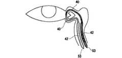
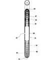
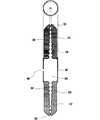
本発明の実施形態においては、挿管器具は柔らかいプラスチックチューブで作られている。本発明はすでに本発明者が発明したヌンチャク型シリコーンチューブと外観は同じであるが、図2に示されるようにブジーで涙道内に押し込みやすいように腔面に段g1g2g3g4g5が付けられており、さらに挿入後、ヌンチャクチューブの中央に設けられている切れ目又は孔から洗浄針を挿入して内腔を洗浄できるように内腔54が両端53に及び両端53が開いている。図3に示されるように、ヌンチャク型チューブの太いチューブの壁が中央に近づくにつれて、段々と肉薄になるとプローブの先がチューブの腔面に強く当たるようになり挿入しやすくなる。図4に示されるように、図3に示されるチューブの腔面に凹凸や波などを付け、ざらつくようにするとさらに挿入しやすくなる。
本発明の挿管器具は、柔らかい材質例えばプラスチックチューブでできているので、生体にやさしく、チューブの腔面に段や波や凹凸があるのでそこに金属ブジーの先が当りチューブを涙道内に押し込みやすくなる。さらに、両端は開いているのでチューブの中央の切れ目又は孔48から内腔54に薬液や洗浄液を流し、チューブの内腔54を洗浄し清潔に保つことができる。図5に示されるようにヌンチャク型チューブの半分の色が残りの半分の色と異なるときは、内視鏡で鼻腔に出ているヌンチャク型チューブの両側を観察できるが、チューブが上涙点から挿入したものか下涙点から挿入したものかを簡単に色により識別でき、小さな鉗子例えばハートマン鉗子で引っ張って容易にセンターリングを行うことができる。着色する代わりにチューブに線や点などの印を付けて区別できるようにしてもよい。単一の太さで腔面がなめらかな通常のチューブもヌンチャク型シリコーンチューブに比較し安定性はよくないが、涙道再建に使用されている。図6に示されるように単一の太さのチューブの腔面に段や波や凹凸をつけると内腔に挿入した金属プローブで涙道内にチューブを押し込みやすくなる。
【実施例】
図2や図4に示されるように、本発明はヌンチャク型をしており、細いチューブの両側に連結している太いチューブの腔面に段や波や凹凸が付けられている。本発明はヌンチャク型チューブの中にブジーを挿入してチューブを涙道内に押し込むが図2、4、6、7、8、9、10に示されるようにチューブの腔面に段g1g2g3g4g5や波や凹凸58が付いているとそこにブジーの先が当り、効果的にチューブを涙道内に押し込むことができる。
本発明の器具を正しく留置すると、中央部をピンセットでつまんで5mmほど引き出しても、瞬目をさせることにより元の状態に戻る。さらに、チューブの両端53は開いているので、チューブの中央に設けられている切れ目や孔48から洗浄針62を挿入して洗浄液を注入しチューブの内腔54を洗浄することができる。図2に示されるように、チューブの両端の内径56はチューブに挿入するプローブ61の外径より小さくなっている。例えばプローブ61の太さが0.4mmのときはチューブの両端の内径56は0.3mmとなっている。
以上のように本発明のヌンチャク型の挿管器具は、涙道内における安定性が極めてよく、自然に抜け出してくることはなく、涙道内に留置後、洗浄できるので清潔を保つことができる。ヌンチャク型チューブを上下涙点から挿入したときに、内視鏡でチューブの両側が下鼻道から出ているのを観察することができる。図2、3、4、5、7、9、10に示されるように、ヌンチャク型チューブの半分の色が残り半分の色と異なるとチューブの中心がどこにあるかを容易に知ることができるだけでなく、下鼻道に出ている2本のチューブが上涙点から挿入されたものか下涙点から挿入されたものかを内視鏡で容易に判別することができる。そして、下鼻道に出ている2本のチューブの一方を内視鏡下で小さな鉗子で引っ張ることによりチューブのセンターリングを容易に行うことができる。図8に示されるように、チューブを着色する代わりにチューブに異なる数の線や点を付けて識別できるようにしてもよい。例えば図8に示されるようにチューブの一方の先端から10mmと15mmの点に2本線を入れ、もう一方の先端から10mmと15mmの点に一本線を入れる。線はチューブの壁が線状に少し盛り上がるようにして付けてもよい。
図7に示されるように本発明の腔面にオリーブオイルなどの潤滑剤を配置しておくとさらに挿入しやすくなる(例えば米国特許 Patent No.US6,383,192 B1を参照)。また、図8に示されるように本発明においてはチューブ壁の一部または全部に薬液を染み込ませてドラッグデリバリーシステムとして使用することができる。
ヌンチャク型チューブは中央部が細く両側部より柔らかくなっているので持ち上げると逆U字型になる。中央部の細いチューブは涙小管の中を走り、涙嚢に達する。細いチューブに連結している太いチューブは涙嚢−鼻涙管の中に含まれ、下方に向って走り、重力により涙小管の中の細いチューブを引っ張っている。従って、涙道内に挿入したとき安定性がよいのである。この安定性のためにはヌンチャク型チューブの中央部が細いということよりも柔らかく、涙点から涙嚢に届くほどの十分な長さ(例えば30mmの長さ)があるということが重要である。図9に示すように中央部の外径がその両側部分と同じでも中央部が肉薄で十分な長さがあればヌンチャク型シリコーンチューブと同じく逆U字型になり、安定性がよい。図10に示すように中央部の外径が両側部分より少し太くても十分に肉薄で必要な長さがあれば、ヌンチャク型シリコーンチューブと同じく逆U字型になり安定性がよい。
本発明は一般的な症例に単独でよく使用されるが、図11のように涙丘を移動しないで行う難治症例に対する涙道再建手術にもジョーンズチューブと共に使用される。図12に示されるように、程度の強い難治症例のときは涙丘移動を行ってからジョーンズチューブなどと共に挿入することで涙道を再建することができる。
【発明の効果】
本発明による涙道内挿管器具は挿入しやすく、挿入後、チューブの清潔を保つため洗浄することができる。
【図面の簡単な説明】
【図1】従来のヌンチャク型チューブの説明図
【図2】本発明の1つの実施例による挿管器具を示す断面図
【図3】本発明の他の実施例による挿管器具を示す断面図
【図4】本発明の他の実施例による挿管器具を示す断面図
【図5】本発明のヌンチャク型チューブの説明図
【図6】本発明の他の実施例による挿管器具を示す断面図
【図7】本発明の他の実施例による挿管器具を示す断面図
【図8】本発明の他の実施例による挿管器具を示す断面図
【図9】本発明の他の実施例による挿管器具を示す断面図
【図10】本発明の他の実施例による挿管器具を示す断面図
【図11】本発明のヌンチャク型チューブの使用法を示す説明図
【図12】本発明のヌンチャク型チューブの使用法を示す説明図
【符号の説明】
1 上涙点
2 下涙点
7 上涙小管水平部
8 下涙小管水平部
9 総涙小管
11 涙嚢
12 鼻涙管
31 涙丘
32 鼻腔
33 鼻粘膜前弁
34 鼻粘膜後弁
35 涙嚢粘膜前弁
36 涙嚢粘膜後弁
40 細いチューブ
42 太いチューブ
48 中央部に設けられた小さな切れ目又は孔
49 小さな切れ目
53 先端部
54 チューブの内腔
55 オリーブ油(潤滑剤)
56 先端部の内径
57 平滑な腔面
58 腔面に付けられた凹凸や波
61 プローブ
62 涙洗針
91 ジョーンズチューブ
g1g2g3g4g5 腔面に付けられた段BACKGROUND OF THE INVENTION
The present invention relates to an intra lacrimal intubation device that can clean the lumen of a tube in order to maintain cleanliness with an intra lacrimal intubation device for treatment of lacrimal passage obstruction, and is designed to be easily inserted.
[Prior art]
In the lacrimal passage occlusion reconstruction operation, both are the inventions of the present inventors, but a nunchaku type silicone tube inserted from the upper and lower punctum is used as shown in FIG. (See Kuriaki Kurihashi: Dacology, Medical Sakai Publishing 1998, Katsuaki Kurihashi: Nunchaku type silicone tube. See Ophthalmic Practice 52: 100-112, 1999). Nunchaku type silicone tube is disclosed in US Pat. No. 5,437,625, US Pat. US Pat. No. 6,383,192B1, Japanese Patent No. 2539325 (Japanese Patent Laid-Open No. 6-142129), Japanese Patent No. 2811283 (Japanese Patent Laid-Open No. 8-24285), Japanese Patent Application No. 8-110618 (Japanese Patent Laid-Open No. 9-276318), Japanese Patent Application No. 8 -214093 (Japanese Patent Laid-Open No. 10-33584) and Japanese Patent Application No. 11-170456.
[Problems to be solved by the invention]
The nunchaku type silicone tube invented by the present inventor is the most popular lacrimal stent in Japan. Nunchaku is a weapon used in Chinese martial arts and consists of a thick part on both sides and a thin part on the center. The nunchaku-type silicone tube is a nunchaku-type lacrimal stent having a thin tube or rod at the center and a thick tube connected to both sides thereof. The nunchaku-type silicone tube has good stability in the lacrimal passage, and when inserted correctly, even if it is pulled out about 5 mm from the punctum, it returns to its original position by blinking. As described above, the nunchaku type silicone tube is most used in Japan because it is not only stable but also easy to insert and remove. The Nunchaku type silicone tube that is currently popular is blind at both ends, and it is difficult to wash the lumen of the tube by inserting a washing needle into the tube after insertion. Therefore, after the nunchaku type silicone tube is inserted into the lacrimal passage, blood may enter the tube and bacteria may grow. Further, the cavity surface of the nunchaku-type silicone tube is smooth, and the probe may slip and be difficult to insert. The present inventor has invented a lacrimal stent that has a step or bulge on the cavity surface of the nunchaku-type silicone tube and the probe is difficult to slide in the tube (see, for example, US Patent No. US 6,383,192 B1). As shown in FIG. 1, when the nunchaku-type silicone tube is correctly inserted from the upper punctum 1 and the
The object of the present invention is easy to insert, and can be washed to keep the lumen of the tube clean after insertion, and after insertion, both sides of the nunchaku-type silicone tube protruding into the lower nasal passage are inserted from the upper punctum It is an object of the present invention to provide an intubation device that can identify whether it is inserted from the lower punctum by color or marking.
[Means for Solving the Problems]
The detailed solution of the present invention is an intubation device according to
DETAILED DESCRIPTION OF THE INVENTION
In an embodiment of the invention, the intubation device is made of a soft plastic tube. The present invention has the same appearance as the nunchaku-type silicone tube already invented by the present inventor, but as shown in FIG. 2, a step g1 g2 g3 g4 is formed on the cavity surface so that it can be easily pushed into the lacrimal passage with a bougie. g5 is attached, and after insertion, the
Since the intubation device of the present invention is made of a soft material such as a plastic tube, it is gentle to the living body, and since there are steps, waves, and irregularities on the cavity surface of the tube, the tip of the metal bougie hits there and it is easy to push the tube into the lacrimal passage Become. Furthermore, since both ends are open, a chemical solution or a cleaning solution can be flowed from the central cut or
【Example】
As shown in FIGS. 2 and 4, the present invention has a nunchaku shape, and steps, waves, and irregularities are provided on the cavity surface of the thick tube connected to both sides of the thin tube. In the present invention, a bougie is inserted into a nunchaku tube and the tube is pushed into the lacrimal passage. As shown in FIGS. 2, 4, 6, 7, 8, 9, and 10, steps g1 g2 are formed on the tube cavity surface. If g3 g4 g5 or a wave or
When the instrument of the present invention is correctly placed, even if the center part is pinched with tweezers and pulled out by about 5 mm, the original state is restored by blinking. Further, since both
As described above, the nunchaku-type intubation device of the present invention is extremely stable in the lacrimal passage, does not come out naturally, and can be cleaned after being placed in the lacrimal passage, so that cleanliness can be maintained. When the nunchaku tube is inserted from the upper and lower punctums, it can be observed with an endoscope that both sides of the tube protrude from the lower nasal passage. As shown in Figures 2, 3, 4, 5, 7, 9, and 10, when the half color of the nunchaku tube is different from the other half, you can easily know where the center of the tube is. In addition, it is possible to easily determine with the endoscope whether the two tubes protruding from the lower nasal passage are inserted from the upper punctum or the lower punctum. Then, the tube can be easily centered by pulling one of the two tubes coming out of the lower nasal passage with a small forceps under the endoscope. As shown in FIG. 8, instead of coloring the tube, the tube may be identified with a different number of lines or dots. For example, as shown in FIG. 8, two lines are inserted at
As shown in FIG. 7, it is easier to insert a lubricant such as olive oil on the cavity surface of the present invention (see, for example, US Patent No. US 6,383,192 B1). Further, as shown in FIG. 8, in the present invention, a drug solution can be soaked into a part or all of the tube wall and used as a drug delivery system.
The nunchaku type tube is thin at the center and softer than both sides, so it becomes an inverted U shape when lifted. A thin tube in the middle runs through the lacrimal tubule and reaches the lacrimal sac. The thick tube connected to the thin tube is contained in the lacrimal sac-nasolacrimal duct, runs downward and pulls the thin tube in the lacrimal tubule by gravity. Therefore, stability is good when inserted into the lacrimal passage. For this stability, it is important that the central portion of the nunchaku tube is softer than being thin and has a sufficient length (for example, a length of 30 mm) to reach the lacrimal sac from the punctum. As shown in FIG. 9, even if the outer diameter of the central portion is the same as the both side portions, if the central portion is thin and has a sufficient length, it becomes an inverted U-shape like the nunchaku type silicone tube and has good stability. As shown in FIG. 10, even if the outer diameter of the central portion is a little thicker than both side portions, if it is sufficiently thin and has a required length, it becomes an inverted U-shape like the nunchaku type silicone tube and has good stability.
Although the present invention is often used alone for general cases, it is also used with a Jones tube for lacrimal reconstruction for intractable cases performed without moving the lacrimal cone as shown in FIG. As shown in FIG. 12, in the case of a severe intractable case, the lacrimal passage can be reconstructed by inserting it with the Jones tube after moving the lacrimal cone.
【The invention's effect】
The lacrimal intubation device according to the present invention is easy to insert and can be washed after insertion to keep the tube clean.
[Brief description of the drawings]
FIG. 1 is an explanatory view of a conventional nunchaku tube. FIG. 2 is a cross-sectional view showing an intubation device according to one embodiment of the present invention. FIG. 3 is a cross-sectional view showing an intubation device according to another embodiment of the present invention. 4 is a sectional view showing an intubation device according to another embodiment of the present invention. FIG. 5 is an explanatory view of a nunchaku tube according to the present invention. FIG. 6 is a sectional view showing an intubation device according to another embodiment of the present invention. FIG. 8 is a sectional view showing an intubation instrument according to another embodiment of the present invention. FIG. 8 is a sectional view showing an intubation instrument according to another embodiment of the present invention. FIG. 10 is a cross-sectional view showing an intubation instrument according to another embodiment of the present invention. FIG. 11 is an explanatory view showing how to use the nunchaku tube of the present invention. FIG. 12 shows how to use the nunchaku tube of the present invention. Explanatory drawing showing 【Explanation of symbols】
DESCRIPTION OF SYMBOLS 1
56
Claims (5)
Translated fromJapanesePriority Applications (1)
| Application Number | Priority Date | Filing Date | Title |
|---|---|---|---|
| JP2003205566AJP4313110B2 (en) | 2003-06-28 | 2003-06-28 | Lacrimal intubation device |
Applications Claiming Priority (1)
| Application Number | Priority Date | Filing Date | Title |
|---|---|---|---|
| JP2003205566AJP4313110B2 (en) | 2003-06-28 | 2003-06-28 | Lacrimal intubation device |
Publications (2)
| Publication Number | Publication Date |
|---|---|
| JP2005013698A JP2005013698A (en) | 2005-01-20 |
| JP4313110B2true JP4313110B2 (en) | 2009-08-12 |
Family
ID=34189973
Family Applications (1)
| Application Number | Title | Priority Date | Filing Date |
|---|---|---|---|
| JP2003205566AExpired - Fee RelatedJP4313110B2 (en) | 2003-06-28 | 2003-06-28 | Lacrimal intubation device |
Country Status (1)
| Country | Link |
|---|---|
| JP (1) | JP4313110B2 (en) |
Cited By (1)
| Publication number | Priority date | Publication date | Assignee | Title |
|---|---|---|---|---|
| WO2014034367A1 (en)* | 2012-08-31 | 2014-03-06 | 株式会社カネカ | Lacrimal duct tube |
Families Citing this family (10)
| Publication number | Priority date | Publication date | Assignee | Title |
|---|---|---|---|---|
| US8235932B2 (en)* | 2009-01-09 | 2012-08-07 | Becker Bruce B | Side-by-side lacrimal intubation threader and method |
| WO2011049198A1 (en)* | 2009-10-22 | 2011-04-28 | 株式会社カネカ | Tube device for insertion into lacrimal passage |
| JP2011200601A (en)* | 2010-03-26 | 2011-10-13 | Kaneka Corp | Lacrimal duct tube |
| WO2013111435A1 (en)* | 2012-01-26 | 2013-08-01 | 株式会社カネカ | Lacrimal duct tube |
| KR101425636B1 (en)* | 2013-07-05 | 2014-08-01 | 임한웅 | Nasolacrimal duct tube with lacrimal passage |
| JP6581909B2 (en)* | 2014-01-22 | 2019-09-25 | 株式会社カネカ | Lacrimal tube |
| WO2015111553A1 (en)* | 2014-01-22 | 2015-07-30 | 株式会社カネカ | Lacrimal tube |
| JP6557815B2 (en)* | 2017-01-20 | 2019-08-14 | 竜司 湯田 | Lacrimal catheter |
| JP7169104B2 (en)* | 2017-07-12 | 2022-11-10 | 株式会社カネカ | lacrimal tube |
| CN111110547A (en)* | 2019-12-19 | 2020-05-08 | 姚培好 | Operation method |
- 2003
- 2003-06-28JPJP2003205566Apatent/JP4313110B2/ennot_activeExpired - Fee Related
Cited By (3)
| Publication number | Priority date | Publication date | Assignee | Title |
|---|---|---|---|---|
| WO2014034367A1 (en)* | 2012-08-31 | 2014-03-06 | 株式会社カネカ | Lacrimal duct tube |
| JPWO2014034367A1 (en)* | 2012-08-31 | 2016-08-08 | 株式会社カネカ | Lacrimal tube |
| US9913753B2 (en) | 2012-08-31 | 2018-03-13 | Kaneka Corporation | Lacrimal duct tube |
Also Published As
| Publication number | Publication date |
|---|---|
| JP2005013698A (en) | 2005-01-20 |
Similar Documents
| Publication | Publication Date | Title |
|---|---|---|
| JP4313110B2 (en) | Lacrimal intubation device | |
| US4305395A (en) | Method of positioning tubing in lacrimal ducts and intubation set therefor | |
| US6344047B1 (en) | Instrument for inserting a punctum plug and method for manufacturing the instrument | |
| JP2958219B2 (en) | Endoscopic ligation kit | |
| US5423777A (en) | Punctum plug | |
| US6083188A (en) | Lacrimal silicone stent with very large diameter segment insertable transnasally | |
| JP6510503B2 (en) | Inserter for tubular medical implant devices | |
| JP2003534039A5 (en) | ||
| WO2001067995A1 (en) | Nasolacrimal duct tube used for lacrimal duct reformation operation, and nasolacrimal duct tube instrument | |
| JP3558924B2 (en) | Intubation device for lacrimal canal reconstruction | |
| JP4644438B2 (en) | Brim lacrimal stent | |
| FR2771297A1 (en) | Bi-canicular probe, used to treat lacrimation | |
| JP4339635B2 (en) | Punctum plug | |
| CN101049270B (en) | Vitreous cavity support for treating retinal diseases and manufacturing method thereof | |
| JP2005110930A (en) | Lacrimal punctum plug set | |
| JP2004202276A (en) | Intubator implement for reconstructing lacrimal passage | |
| JP4280128B2 (en) | Punctum plug | |
| CN105748193A (en) | Adjustable glaucoma drainage tube | |
| JP2005110765A (en) | Lacrimal punctum plug set | |
| TWI457116B (en) | Lacrimal punctum measurement and occlusion | |
| JP2011160839A (en) | Oral cavity cleaning instrument | |
| CN204618557U (en) | A kind of intraoculai foreign body pocket | |
| CN201135547Y (en) | Safety Lacrimal Drainage Tube | |
| WO2019044884A1 (en) | Backflush needle | |
| US20100185137A1 (en) | Device for treatment of watering of the eye |
Legal Events
| Date | Code | Title | Description |
|---|---|---|---|
| A621 | Written request for application examination | Free format text:JAPANESE INTERMEDIATE CODE: A621 Effective date:20060508 | |
| RD02 | Notification of acceptance of power of attorney | Free format text:JAPANESE INTERMEDIATE CODE: A7422 Effective date:20060601 | |
| A131 | Notification of reasons for refusal | Free format text:JAPANESE INTERMEDIATE CODE: A131 Effective date:20081209 | |
| A521 | Written amendment | Free format text:JAPANESE INTERMEDIATE CODE: A523 Effective date:20090204 | |
| A521 | Written amendment | Free format text:JAPANESE INTERMEDIATE CODE: A523 Effective date:20090204 | |
| TRDD | Decision of grant or rejection written | ||
| A01 | Written decision to grant a patent or to grant a registration (utility model) | Free format text:JAPANESE INTERMEDIATE CODE: A01 Effective date:20090512 | |
| A01 | Written decision to grant a patent or to grant a registration (utility model) | Free format text:JAPANESE INTERMEDIATE CODE: A01 | |
| A61 | First payment of annual fees (during grant procedure) | Free format text:JAPANESE INTERMEDIATE CODE: A61 Effective date:20090514 | |
| FPAY | Renewal fee payment (event date is renewal date of database) | Free format text:PAYMENT UNTIL: 20120522 Year of fee payment:3 | |
| R150 | Certificate of patent or registration of utility model | Free format text:JAPANESE INTERMEDIATE CODE: R150 | |
| FPAY | Renewal fee payment (event date is renewal date of database) | Free format text:PAYMENT UNTIL: 20120522 Year of fee payment:3 | |
| FPAY | Renewal fee payment (event date is renewal date of database) | Free format text:PAYMENT UNTIL: 20130522 Year of fee payment:4 | |
| FPAY | Renewal fee payment (event date is renewal date of database) | Free format text:PAYMENT UNTIL: 20130522 Year of fee payment:4 | |
| FPAY | Renewal fee payment (event date is renewal date of database) | Free format text:PAYMENT UNTIL: 20140522 Year of fee payment:5 | |
| R250 | Receipt of annual fees | Free format text:JAPANESE INTERMEDIATE CODE: R250 | |
| LAPS | Cancellation because of no payment of annual fees |