JP4312368B2 - Injection needle retractable syringe - Google Patents
Injection needle retractable syringeDownload PDFInfo
- Publication number
- JP4312368B2 JP4312368B2JP2000315936AJP2000315936AJP4312368B2JP 4312368 B2JP4312368 B2JP 4312368B2JP 2000315936 AJP2000315936 AJP 2000315936AJP 2000315936 AJP2000315936 AJP 2000315936AJP 4312368 B2JP4312368 B2JP 4312368B2
- Authority
- JP
- Japan
- Prior art keywords
- needle
- hub
- distal end
- plunger
- outer hub
- Prior art date
- Legal status (The legal status is an assumption and is not a legal conclusion. Google has not performed a legal analysis and makes no representation as to the accuracy of the status listed.)
- Expired - Lifetime
Links
Images


Classifications
- A—HUMAN NECESSITIES
- A61—MEDICAL OR VETERINARY SCIENCE; HYGIENE
- A61M—DEVICES FOR INTRODUCING MEDIA INTO, OR ONTO, THE BODY; DEVICES FOR TRANSDUCING BODY MEDIA OR FOR TAKING MEDIA FROM THE BODY; DEVICES FOR PRODUCING OR ENDING SLEEP OR STUPOR
- A61M5/00—Devices for bringing media into the body in a subcutaneous, intra-vascular or intramuscular way; Accessories therefor, e.g. filling or cleaning devices, arm-rests
- A61M5/178—Syringes
- A61M5/31—Details
- A61M5/32—Needles; Details of needles pertaining to their connection with syringe or hub; Accessories for bringing the needle into, or holding the needle on, the body; Devices for protection of needles
- A61M5/3205—Apparatus for removing or disposing of used needles or syringes, e.g. containers; Means for protection against accidental injuries from used needles
- A61M5/321—Means for protection against accidental injuries by used needles
- A61M5/322—Retractable needles, i.e. disconnected from and withdrawn into the syringe barrel by the piston
- A61M5/3234—Fully automatic needle retraction, i.e. in which triggering of the needle does not require a deliberate action by the user
- A—HUMAN NECESSITIES
- A61—MEDICAL OR VETERINARY SCIENCE; HYGIENE
- A61M—DEVICES FOR INTRODUCING MEDIA INTO, OR ONTO, THE BODY; DEVICES FOR TRANSDUCING BODY MEDIA OR FOR TAKING MEDIA FROM THE BODY; DEVICES FOR PRODUCING OR ENDING SLEEP OR STUPOR
- A61M5/00—Devices for bringing media into the body in a subcutaneous, intra-vascular or intramuscular way; Accessories therefor, e.g. filling or cleaning devices, arm-rests
- A61M5/002—Packages specially adapted therefor, e.g. for syringes or needles, kits for diabetics
- A—HUMAN NECESSITIES
- A61—MEDICAL OR VETERINARY SCIENCE; HYGIENE
- A61M—DEVICES FOR INTRODUCING MEDIA INTO, OR ONTO, THE BODY; DEVICES FOR TRANSDUCING BODY MEDIA OR FOR TAKING MEDIA FROM THE BODY; DEVICES FOR PRODUCING OR ENDING SLEEP OR STUPOR
- A61M5/00—Devices for bringing media into the body in a subcutaneous, intra-vascular or intramuscular way; Accessories therefor, e.g. filling or cleaning devices, arm-rests
- A61M5/178—Syringes
- A61M5/31—Details
- A61M5/32—Needles; Details of needles pertaining to their connection with syringe or hub; Accessories for bringing the needle into, or holding the needle on, the body; Devices for protection of needles
- A61M5/3202—Devices for protection of the needle before use, e.g. caps
- A—HUMAN NECESSITIES
- A61—MEDICAL OR VETERINARY SCIENCE; HYGIENE
- A61M—DEVICES FOR INTRODUCING MEDIA INTO, OR ONTO, THE BODY; DEVICES FOR TRANSDUCING BODY MEDIA OR FOR TAKING MEDIA FROM THE BODY; DEVICES FOR PRODUCING OR ENDING SLEEP OR STUPOR
- A61M5/00—Devices for bringing media into the body in a subcutaneous, intra-vascular or intramuscular way; Accessories therefor, e.g. filling or cleaning devices, arm-rests
- A61M5/178—Syringes
- A61M5/31—Details
- A61M5/32—Needles; Details of needles pertaining to their connection with syringe or hub; Accessories for bringing the needle into, or holding the needle on, the body; Devices for protection of needles
- A61M5/34—Constructions for connecting the needle, e.g. to syringe nozzle or needle hub
- A61M5/344—Constructions for connecting the needle, e.g. to syringe nozzle or needle hub using additional parts, e.g. clamping rings or collets
- A—HUMAN NECESSITIES
- A61—MEDICAL OR VETERINARY SCIENCE; HYGIENE
- A61M—DEVICES FOR INTRODUCING MEDIA INTO, OR ONTO, THE BODY; DEVICES FOR TRANSDUCING BODY MEDIA OR FOR TAKING MEDIA FROM THE BODY; DEVICES FOR PRODUCING OR ENDING SLEEP OR STUPOR
- A61M5/00—Devices for bringing media into the body in a subcutaneous, intra-vascular or intramuscular way; Accessories therefor, e.g. filling or cleaning devices, arm-rests
- A61M5/178—Syringes
- A61M5/31—Details
- A61M5/32—Needles; Details of needles pertaining to their connection with syringe or hub; Accessories for bringing the needle into, or holding the needle on, the body; Devices for protection of needles
- A61M5/34—Constructions for connecting the needle, e.g. to syringe nozzle or needle hub
- A61M5/347—Constructions for connecting the needle, e.g. to syringe nozzle or needle hub rotatable, e.g. bayonet or screw
- A—HUMAN NECESSITIES
- A61—MEDICAL OR VETERINARY SCIENCE; HYGIENE
- A61M—DEVICES FOR INTRODUCING MEDIA INTO, OR ONTO, THE BODY; DEVICES FOR TRANSDUCING BODY MEDIA OR FOR TAKING MEDIA FROM THE BODY; DEVICES FOR PRODUCING OR ENDING SLEEP OR STUPOR
- A61M5/00—Devices for bringing media into the body in a subcutaneous, intra-vascular or intramuscular way; Accessories therefor, e.g. filling or cleaning devices, arm-rests
- A61M5/178—Syringes
- A61M5/31—Details
- A61M5/32—Needles; Details of needles pertaining to their connection with syringe or hub; Accessories for bringing the needle into, or holding the needle on, the body; Devices for protection of needles
- A61M5/34—Constructions for connecting the needle, e.g. to syringe nozzle or needle hub
- A61M5/349—Constructions for connecting the needle, e.g. to syringe nozzle or needle hub using adhesive bond or glues
- A—HUMAN NECESSITIES
- A61—MEDICAL OR VETERINARY SCIENCE; HYGIENE
- A61M—DEVICES FOR INTRODUCING MEDIA INTO, OR ONTO, THE BODY; DEVICES FOR TRANSDUCING BODY MEDIA OR FOR TAKING MEDIA FROM THE BODY; DEVICES FOR PRODUCING OR ENDING SLEEP OR STUPOR
- A61M5/00—Devices for bringing media into the body in a subcutaneous, intra-vascular or intramuscular way; Accessories therefor, e.g. filling or cleaning devices, arm-rests
- A61M5/50—Devices for bringing media into the body in a subcutaneous, intra-vascular or intramuscular way; Accessories therefor, e.g. filling or cleaning devices, arm-rests having means for preventing re-use, or for indicating if defective, used, tampered with or unsterile
- A61M5/5013—Means for blocking the piston or the fluid passageway to prevent illegal refilling of a syringe
- A61M5/502—Means for blocking the piston or the fluid passageway to prevent illegal refilling of a syringe for blocking the piston
- A—HUMAN NECESSITIES
- A61—MEDICAL OR VETERINARY SCIENCE; HYGIENE
- A61M—DEVICES FOR INTRODUCING MEDIA INTO, OR ONTO, THE BODY; DEVICES FOR TRANSDUCING BODY MEDIA OR FOR TAKING MEDIA FROM THE BODY; DEVICES FOR PRODUCING OR ENDING SLEEP OR STUPOR
- A61M5/00—Devices for bringing media into the body in a subcutaneous, intra-vascular or intramuscular way; Accessories therefor, e.g. filling or cleaning devices, arm-rests
- A61M5/50—Devices for bringing media into the body in a subcutaneous, intra-vascular or intramuscular way; Accessories therefor, e.g. filling or cleaning devices, arm-rests having means for preventing re-use, or for indicating if defective, used, tampered with or unsterile
- A61M5/508—Means for preventing re-use by disrupting the piston seal, e.g. by puncturing
Landscapes
- Health & Medical Sciences (AREA)
- Engineering & Computer Science (AREA)
- Life Sciences & Earth Sciences (AREA)
- Animal Behavior & Ethology (AREA)
- Anesthesiology (AREA)
- Biomedical Technology (AREA)
- Heart & Thoracic Surgery (AREA)
- Hematology (AREA)
- Environmental & Geological Engineering (AREA)
- Vascular Medicine (AREA)
- General Health & Medical Sciences (AREA)
- Public Health (AREA)
- Veterinary Medicine (AREA)
- Infusion, Injection, And Reservoir Apparatuses (AREA)
- Nozzles (AREA)
- Catching Or Destruction (AREA)
- Containers And Packaging Bodies Having A Special Means To Remove Contents (AREA)
Abstract
Description
Translated fromJapanese【0001】
【発明の属する技術分野】
本発明は、シリンジと注射針アッセンブリに関する。より詳細には、本発明は、使用後にシリンジバレル内への針状カニューレの自動引込みを考慮する構造を有するシリンジおよび注射針アッセンブリと、注射針アッセンブリを製造する方法とに関する。
【0002】
【従来の技術】
近年、生成物を収容する使用済みの皮下注射器を処分するとき、偶然に又は不注意な取り扱いにより皮下注射器を自分自身に突き刺す注射器の使用者及び医療専門家への病気、感染などの転移に関して高まりつつある問題が生じた。針状カニューレの製品が使用される病院の多くの分野においては、廃棄用容器が用意されている。それで、シリンジ又は他の針状カニューレの製品は、安全で堅固な容器に直ちに捨てられる。しかしながら、処分用容器が直ちに入手可能でない又は実用的でない、そして自蔵式の安全上の機能を有する製品が望まれている緊急治療室のような医療業務がある。理論的には、そのようなシリンジが薬剤を注入するため又は別の目的のために使用された後、シリンジ又は注射針アッセンブリ内に収容される安全装置が、鋭利な注射針先端とのさらなる接触を妨げるために作動させられる。安全なシリンジの1つのタイプは、鋭利な注射針先端とのさらなる接触の機会を最小にするために、皮下注射針をシリンジバレル内へ引込むことができる構造を含んでいる。
【0003】
そのような注射針引込み可能なシリンジの先行技術の1つは、バレルの側壁から皮下注射針に連結されているバレルの前方壁を分離できる壊れ易い領域を含んでいる。そのシリンジは、また、使用者が、ピストンを力強くねじり、壊れ易い構造を壊し、皮下注射針を含んでいる前方壁をシリンジバレル内に引き込むように、選択的にピストンを前方壁に取り付けるための構造を前方壁の内側及びピストンの外側に収めている。このデザインは、シリンジバレルのデザインにおいて妥協案を必要とする。そのバレルは、通常の使用中無傷のままであるように十分に強くなければならず、しかし、力に関係なくいかなる使用者によっても切り離されるべく十分に弱くなければならない。
【0004】
先行技術は、また、他の注射針引込み可能なシリンジを含む。これらのシリンジは、ニードルキャリアをプランジャロッドの作用によりシリンジバレルから強引に外し、シリンジバレル内に引込むことができるようにニードルキャリアに係合する構造を有する。注射針引込み可能なシリンジの多くの先行技術は、上記したシリンジと同様な欠陥を有する。特に、引込み可能なシリンジの注射針またはニードルキャリアは、特に高粘性液体を、注入中に経験する相当な液圧と、薬ビンのゴム製栓体を貫通することに伴う力とをたびたび含む通常の使用中に、シリンジバレルによりしっかりと保持されなければならない。注射器用バレルは、通常使用時の力に打ち負かされることなく、なおかつ、シリンジバレルの開いた基端部から延びているプランジャロッドに加えられる力により、外され得る程度にニードルキャリアを保持しなければならない。通常使用時の力に耐えるのに十分な強さを持って作られた、注射針引込み可能なシリンジの多くの先行技術のデザインは、容易に外され得ないニードルキャリアを有する。また、注射針または注射針キャリアの容易な取外しは、通常使用時の力に耐えない構造につながることがある。このことは、特に、使用者が使用時に皮下注射針の大きさを選択できるように、注射針アッセンブリが着脱可能とされるように構成されているニードルキャリアに当てはまる。これらのシリンジは、また、注射針の取付け取外しにおける高いトルク及び力に耐えなければならない。さらに、注射針引込み可能なシリンジは、使用時の困難性を増す両手で扱う引込手順を必要とする。
【0005】
先行技術は、また、シリンジアッセンブリの通常の使用中、所定位置で保持されているバネ付ニードルアッセンブリと、薬剤がプランジャロッドの空洞部に入らないようにシリンジアッセンブリの通常の使用中、シールされている中空のプランジャロッドとを含む注射針引込み式シリンジを含む。
【0006】
これらのシリンジは、シリンジがその意図された目的のために使用された後、注射針がプランジャロッドの空洞部に入るように、バネ付注射針及びプランジャロッドの空洞部開口を解放できる構造を有しなければならない。注射針引込み式シリンジは、注射針引込み可能なシリンジに関し先に述べられたシリンジと同じデザイン上の問題を有している。特に、プランジャロッドの空洞部は、使用中、薬剤がプランジャロッドに入ることができないように、シールされなければならない。このシールは、度々、比較的粘性のある薬剤を、小さな注射針を通して注入する場合、高い液圧に耐えなければならない。そして、このシールは、それにもかかわらず容易に開けられ、ニードルアッセンブリにより入れることができなければならない。さらに、ニードルアッセンブリは、注入の力によりしっかりと所定位置に保持されなければならない。そして、それにもかかわらず、ニードルアッセンブリが、シリンジ用バレル内、および、プランジャロッド内に引込まれるように、分離可能でなければならない。
【0007】
注射針引込み式シリンジの先行技術には、プラグが注入工程の間に脱落した後、ほぼ間違いなく困難な状態に結びつくプランジャロッドの空洞部を覆うプラグを使用するものがある。さらに、あるものは、使用中、シリンジに対する懸念を引き起こすことになり得るような、ほぼ間違いなく外れる所定位置にシリンジアッセンブリを保持するのにプラグを使用する。さらに、これらのデザインは、取り替え可能なニードルアッセンブリを考慮に入れていない。したがって、これらのデザインは、ヘルスワーカに対し、注射、即ち、実行される処置のために適切な注射針の大きさの任意の選択の自由を許さない。さらに、注射針引込み式シリンジのような安全な製品に対する要求には、標準的なシリンジアッセンブリより以上にあまり費用がかからない製品である要求がついてくる。注射針引込み式アッセンブリの先行技術は、該注射針アッセンブリがその広範囲の使用を可能する費用で作ることができないデザインを提示しているという点で欠点を有する。なぜならば、多くのデザインは、信頼性を得ることに関して非常に厳密な公差を必要とし、高い不良率につながる針状カニューレの繊細な先端を傷つけ得る組立工程を必要とするからである。
【0008】
【発明が解決しようとする課題】
先行技術は、多くの異なる注射針引込み可能なシリンジと、引込むための収容能力を有し、すなわち、注射針がシリンジ用バレルまたはプランジャロッドに入ることができる注射針引込み式シリンジとを示唆しているが、バネは、それにもかかわらず、容易に、意図的に解放され、注射針アッセンブリがプランジャロッドの空洞部に入ることができる一方で、簡単で、複雑でない、信頼のおける、容易に組み立てられ、注入の力に耐える十分な構造的な欠陥がない、注射針引込み式シリンジの必要性がある。また、取り替え可能なバネ付ニードルアッセンブリを有し、使用時に適切な大きさの注射針を選択することができ、また、予め充填することを容易にするための注射針引込み式シリンジの要求がある。また、針状カニューレの繊細な最先端を傷つけることなく大量に容易に組み立てられ得る、注射針引込み式アッセンブリの要求がある。
【0009】
【課題を解決するための手段】
部屋を形成する内面と、開口基端部と、円筒状カラーを含む開口末端部と、鋭利な末端を有する解放要素を有するプランジャとを備えるシリンジバレル用の動作可能な注射針引込み用アッセンブリであって、基端部と、末端部と、その中の通路とを有するアウタハブと、基端部と、末端部と、その中の導管部とを有するインナハブとを含んでなる。インナハブの基端部は、内部と該内部に連結され分離可能な外部とを含んでいる。インナハブの分離可能な外部は、前記アウタハブに連結される。インナハブの末端部がアウタハブの末端部で前記アウタハブの通路に比して小であり、末端側外方に突出する。針状カニューレは、末端部と、インナハブの末端部に連結される基端部と、その中の内腔とを有する。その連結は、内腔が導管部に流体で連通するように作られる。付勢バネは、アウタハブとインナハブとの間に収容される。ねじ係合、接着、超音波溶接などのようなアウタハブをシリンジバレルのカラーに連結する連結手段が設けられる。インナハブおよびアウタハブは、バレル内において鋭利な末端を有する解放要素を有するプランジャの末端の動きにより、解放要素の鋭利な末端が分離可能な外部と内部とを分離するインナハブの部分を切断し、バネが基端部側に針状カニューレを移動させるように構成されている。
【0010】
動作可能な注射針引込み用アッセンブリは、部屋を形成する内面と、開口基端部と、円筒状カラーを含む開口末端部とを有するシリンジバレルをさらに含む。そのカラーは、外面および内面を有する。アウタハブは、カニューレがシリンジバレルから末端側外方に突出するようにカラーに連結される。
【0011】
プランジャは、バレルの内面に液密に係合して摺動可能に位置付けられる。プランジャは、細長い空洞部を内部に備える末端部を有する基部と、基部の末端部に位置付けられる鋭利な末端部を有する解放要素と、基部に解放可能に連結され基部に対し滑り出し可能とされる中空末端部とを含んでいる。末端部の末端においてカバー要素が末端部の末端をシールする。バレルに対するプランジャの末端側への動きが、分離可能な外部を内部から分離すべく解放要素が接触しカバー要素およびインナハブを切り進むように、プランジャの基部を、基部を末端側に移動させながらプランジャの末端部から分離させ、カニューレの末端部がアウタハブの末端部の基端側に位置付けられるように、バネに、針状カニューレを前記基部の空洞部内にはるかに十分に移動させるように、プランジャの基部および末端部は、連結されている。
【0012】
本発明の別の形態は、動作可能な注射針引込み用アッセンブリの製造方法であり、基端部、末端部及びそこを貫通する通路を有するアウタハブを用意するステップと、基端部、末端部及びそこを貫通する導管部を有するインナハブを用意するステップと、末端部、基端部及びそこを貫通する内腔を有する針状カニューレを用意するステップと、圧縮コイルバネを用意するステップと、インナハブの末端部がアウタハブの末端部で通路から届くように、インナハブがアウタハブに連結されることにより、バネが圧縮され、アウタハブ内に保持されるように、インナハブ、バネ及びアウタハブを組み立てるステップと、カニューレの基端部をインナハブの導管部の末端部に配置するステップと、導管部と針状カニューレとの間の空間に接着剤を塗布するステップとを備える。
【0013】
【発明の実施の形態】
この発明は、数多くの異なる形式における実施例により納得されるものであるが、本開示は本発明の思想の一例であると考えられるべきであり、本発明の範囲を説明される実施例に制限することを意図するものではないということを知ったうえで本発明の好ましい実施例は、図面に示され、この中で詳細に説明されるであろう。本発明の範囲は、添付される請求の範囲および均等物によって推し量られるだろう。
【0014】
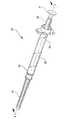
図1乃至11を参照するに、操作できる針引込式シリンジ20は、針引込用アッセンブリ21、シリンジバレル22及びプランジャ23を含んでいる。そのバレルは、部屋27を形成している内面25と、開口基端部28及び外面32、内面33を有する円筒カラー31を備える開口末端部29とを含んでいる。
【0015】
プランジャは、バレルの内面と液密に係合し摺動可能に配されている。プランジャは、その中に細長い空洞部39を持つとともに末端部38を有する基部37を含んでいる。鋭利な末端44を有する解放要素43が、プランジャ23の基部の末端部38に配されている。プランジャ23における中空末端部分46は、基部37に解放可能に連結され、基部に関して滑り出しが可能である。その末端部分のカバー要素が、末端部47を塞いでいる。この実施例においては、カバー要素は、栓体50である。そのカバー要素は、熱可塑性樹脂エラストマ、天然ゴム、合成ゴム及びその化合物の群から選択されたエラストマ材料から作られていることが好ましい。
【0016】
針引込用アッセンブリ21は、基端部55と、末端部56及びそこを貫通する通路57とを有するアウタハブ53を含んでいる。
【0017】
針引込用アッセンブリは、また、基端部62と、末端部63及びそこを貫通する導管部64とを有するインナハブ61を含んでいる。インナハブは、内部分65及び該内部分に連結されている分離可能な外部分67を含んでいる。分離可能な外部分は、アウタハブ53に連結されている。インナハブの末端部63は、末端部56においてアウタハブの通路57より小さく、そこから到達可能であり、好ましくは、そこから末端外方へ突出している。
【0018】
針状カニューレ71は、末端部73と、基端部74及びそこを貫通する管腔75とを有する。カニューレの基端部は、その管腔がインナハブの導管64と流体で連通状態となるようにインナハブの末端部63に連結されている。カニューレの末端部は、鋭利な、即ち、尖った末端側の先端を含むことが好ましい。
【0019】
付勢するバネが、アウタハブとインナハブとの間に収容されている。この好ましい実施例においては、付勢するバネは、圧縮コイルバネ76である。いろいろなバネの種類及びエラストマ―材料などが、インナハブとアウタハブとの間に付勢力をもたらすために使用され得る、即ち、コイルバネは、本発明の範囲内にあるこれらのすべての多くの可能性における単なる典型であるにすぎない。コイルバネは、そのコンパクトな大きさおよびバネの設計容易性のために好ましく、注射針引込み可能なアッセンブリの適切な動作に必要な力をもたらす。
【0020】
組立て中、コイルバネは、インナーハブの内部分全体にわたって置かれ、次にバネの末端部が、アウタハブ内に位置付けられ、インナーハブおよびアウタハブは、お互いに向かって移動せしめられバネを圧縮し、インナーハブの環状固定用凸部70及びアウタハブの環状固定用凹部59の作用により一緒に組み合う。インナーハブとアウタハブとが結合されるとき、コイルバネを圧縮しながら、インナーハブの環状固定用凸部は、アウタハブの環状固定用凹部59にパチンとはめる。凸部および凹部は、逆の手順に比べて部品を組み立てるために言うまでもなく力が必要とされないように形成され、したがって、半永久的な固定状態をもたらし、通常の使用状態の間、インナーハブとアウタハブとが分離できない。インナーハブとアウタハブとを連結する多くの方法がある。そして、ここで示されているスナップ嵌め装置は、本発明の範囲内にあるこれらの方法の単なる典型例にすぎない。特に、接着剤、分離金属製固定用クリップ、超音波溶接、クリンプ加工、内部の固定用成形構造などが、インナーハブおよびアウタハブをともに保持するために使用され得る。本発明の重要な利点は、以下に詳細に説明されるように、インナーハブ、アウタハブ及びバネが、針状カニューレが針引込み用アッセンブリに付け加えられる前に組み立てられ得ることにある。針状カニューレを注射針引込み用アッセンブリに連結する好ましい方法は、針状カニューレの基端部をインナーハブの導管64の末端部内に配することである。導管64の末端部における拡大された、即ち、異なる部分72が、針状カニューレが導管に配置された後、針状カニューレの外周に配されるように接着剤85ための空間をもたらす。
【0021】
注射針引込み用アッセンブリは、また、シリンジバレルのカラーにアウタハブを連結する手段を含んでいる。この好ましい実施例においては、連結手段は、カラーとアウタハブとの間におけるネジ係合用の構造を含んでいる。この好ましい実施例においては、ネジ係合構造は、アウタハブ53の通路57内に少なくとも1つのネジ58を、及び、円筒状カラーの外面32上に少なくとも1つのネジ34を含んでいる。バレルに取り外し可能に連結されている注射針用アッセンブリを設けることのできる能力は、本発明のこの実施例の重要な特徴である。この特徴は、要求される薬剤のタイプおよび注射の部位に関し適切な大きさの注射針およびシリンジの組み合わせを得るために、注射針用アッセンブリやシリンジを交換するように柔軟性を見込んでいる。さらに、好ましい実施例の構造は、特別な訓練が何ら医療従事者に必要とされないように、標準的な皮下注射針を標準的な皮下注射器に対し取付けおよび取外しに必要とされる同様な動きを使って、バレルに対し注射針用アッセンブリの取付け及び取外しを可能とする。
【0022】
本発明の別の重要な特徴は、デッドスペースが少ない注射針引込み用シリンジをもたらす。このことは、その部屋内のほとんど全ての薬剤が注入工程中にシリンジから追い出されることを意味する。多くの引込み可能な及び注射針引込み式シリンジの先行技術は、引込み用又は引込み可能な注射針を保持及び/又は解放するためにその部屋内に突き出ている構造を有する。これらの構造を取り囲む多くの薬剤は、無駄にされ、薬剤がまだバレル内にある間に注射針の引込みが始まってしまうので、送出されないだろう。部屋内に突き出ている構造を有する注射針引込み式シリンジの薬剤損失を最小にするために、使用者は、注射針がまだ患者の中にある間に注射針の引込みの処置を始め得る。注射針は、薬剤が送出されている間に、さらに患者から抜け出る。また、注射針の引込み処置を始めるために力が加えられる結果として、もし注射針が横に移動せしめられるならば患者を傷つける可能性がある。
【0023】
本発明における少ないデッドスペースの特徴を最大限に利用するために、好ましい実施例は、好ましくは凹部であるインナーハブの基端部62に円錐台形をした表面68を含んでいる。この表面は、栓体50の円錐台形をした表面51に合わせるように対応されている。表面51は、凸部であることが好ましい。薬剤がカニューレの管腔を通って部屋から追い出されるとき、栓体50は、栓体の円錐台形をした表面がインナーハブの円錐台形をした表面に非常に近くに接近し、好ましくは接触するまで、シリンジのバレルの末端部に接近する。図は、明瞭にするだけのためにこれら2つの要素の間に僅かな隙間を示している。そして、プランジャのストロークの終了時点において、これらの表面が接触していることが好ましい。また、シリンジのバレルの末端部は、プランジャが部屋から送出する薬剤に対してその最も末端の位置にあるとき、栓体にまた接近し好ましくは接触する円錐台形をした表面30を含んでいる。
【0024】
カラーとアウタハブとの間のネジ係合用の構造は、カラーの外面におけるネジ山と、ハブがカラーにねじ込まれるとき、カラーのネジ山に追従するアウタハブの内面におけるネジの従動子とを含む種々様々のネジ様及びバヨネットタイプの構造を含み得る。この構造は、公知の固定用ルアタイプの注射針アッセンブリとシリンジとの結合体に似ており、そのシリンジのカラーは、その内面にネジを有し、その注射針アッセンブリは、それがルア先端及びカラーにねじ込まれるとき、ハブをカラーのネジ山に追従させるためのそのハブの基盤の2つの外側に向いた凸部を有する。また、カラーの内側は、ネジ従動子を有するアウタハブの外側にネジ山が切られている。
【0025】
先行技術によりよく検討されていない問題点の1つは、漏れである。使用中、シリンジの内容物は、薬剤を、特に粘性のある薬剤を吸い込もうとするとき及び送出するとき、正負両方の高い圧力にさらされる。好ましくは、ガスケットを使用する必要がなく漏れを防止することを助けるために、好ましい実施例では、インナーハブ61に先細になった円筒状表面69及びバレルの円筒状カラ―31の内側に先細になった円筒状表面35を含んでいる。注射針引込み用アッセンブリが、バレルのカラーに係合するとき、該カラーにおける先細になった円筒状表面35が、インナハブにおける先細になった円筒状表面69に係合し、通常の使用中の漏れを防止するためにハブとカラーとの間の接触面をシールする。
【0026】
本発明は、取り外し可能な注射針引込み用アッセンブリとの組み合わせでガスケットを使用しない漏れ防止及び少ないデッドスペースのような特徴を提案することにより、先行技術を越える明確な発展および改良をもたらす。
【0027】
注射針引込み用アッセンブリ21は、必ずしも必要でないが、開口基端部80と、末端部81及びその間でその凹部83を形成している側壁82とを有する細長い注射針用遮蔽体79を含んでいる。その遮蔽体は、アウタハブに取り外し可能に係合し、針状カニューレを覆っている。その遮蔽体は、使用前に汚染から針状カニューレを守ることを助ける。この実施例においては、その遮蔽体は、アウタハブ53の部分に摩擦で係合することが好ましい。しかしながら、シリンジのバレルの部分に係合する遮蔽体を設けることは、本発明の範囲内にある。
【0028】
使用に際し、本発明の注射針引込み用アッセンブリは、プランジャ23を収容するシリンジのバレル22に取り外し可能に連結され得る。注射針用遮蔽体79が注射針引込み用アッセンブリから取り外され、かくして使用するために針状カニューレが曝される。注射針引込み式シリンジは、突き抜け可能な栓体を有する薬瓶から注入可能な液体を引き出すような公知の方法を使用して充填され得る。次に、シリンジは、患者、点滴セット、カテーテル又は他の適切な装置に液体を注入するために使用されてもよい。室内の液体が注射や他の送出の後、栓体の末端は、図9に最もよく示されるようにバレルの部屋の末端部に接触している。この時点で、使用者は、バレルの部屋の末端部における栓体を突くようにプランジャの基端部に軸方向末端に向かってさらなる力を加え、プランジャの末端部分46からプランジャの基部部分37をはずすことを引き起こす。プランジャの基部とプランジャの末端部分との間の連結が、破られる、即ち、無力にされるから、その鋭利な末端部が図10に最もよく示されるように栓体50を押圧し、また、切断して進み、そして内部分65と分離可能な外部分67との間のインナハブを切断して進むように、その基部は、末端部分内をバレルに沿って解放要素43を前進させながら末端へ移動する。解放要素に、インナハブを完全に切断して進ませるプランジャへの基部方向への力の付与により、図11に最もよく示されるように、バネが針状カニューレと一緒にインナハブの内部分をプランジャの細長い空洞内に前進させることができるようになる。使用された針状カニューレは、シリンジアッセンブリの中に安全に収容され、安全な廃棄の準備が整う。
【0029】
本発明のシリンジのバレルおよびプランジャの他の特徴は、プランジャがバレルに関してその最も遠い末端位置に達するとき、フランジ41が環状壁40内に位置し、かくして注射針を再度曝そうとして使用者が基部方向にプランジャを引こうとすることを妨げるように、プランジャの基端部のフランジ41より僅かに大きい、バレルの基端部における基端部向きの環状壁40である。オーバーラップすなわちスナップ嵌め構造のような機械的締め代が、また、環状壁内にフランジをさらに保持するために設けられ得る。この好ましい実施例において、内方に向けられている押縁45が、針状カニューレが引込まれた後、バレル内にプランジャを保持するために設けられている。また、プランジャロッドの第2溝48が、注射針の引込み後、バレルにプランジャを保持することを助けるために使用されてもよい。この第2溝は、内方に向けられている押縁又は他の構造が環状壁40に用いられないならば、使用されることが好ましい。第2環状溝48を用いる場合、プランジャの環状凸部49が注射針の引込み後、溝48に係合するだろう。この係合が、プランジャの末端部分にプランジャの基部を保持する。この場合において、プランジャの末端部分は栓体の摩擦により、バレル内に保持されるだろう。
【0030】
この好ましい実施例において、2つのプランジャ部分の間を滑り出る相対移動を可能とするプランジャの基部37とプランジャの末端部46との間の解放可能な連結は、プランジャの基部部分とプランジャの末端部分との間のスナップ嵌め装置によりもたらされる。特に、プランジャの末端部分46の基端部の内側の環状凸部49が、プランジャの基部37の基端部の環状溝42に係合する。十分な軸力が加えられるとき、解放要素の末端部を、栓体及び分離可能な外部分と内部分との間のインナハブを切断して進ませるように、環状凸部49は環状溝42からはずれる。先に示された構造は本発明の範囲内全体にある多くの可能性のうちの単なる典型例にすぎないので、プランジャの基部部分と末端部分との間の解放可能な連結のための多くの構造、材料及び要素がある。特に、基部および末端部における凸部及び/又は凹部及び/又は割れ目のいずれの結合も、同じ結果を成し遂げ得る。また、その連結は、例えば、2つの要素の間のもろい接着剤の使用、または、脆いプラスチック製凸部、即ち、要素をつなぎ、プランジャに加えられる力で壊れ得る凸部を含む一体化構造として要素を成形することなどにより、外れやすいのみならず壊れやすくしてもよい。壊れ易い連結は、また、せん断ピンで要素を連結することにより作られても良い。作られるせん断ピンは、要求される力レベルで破壊を引き起こすように適切に配置された1又はそれ以上の切り欠き又は応力集中部を備えてプラスチックで作られてもよい。壊れ易い連結は、また、望ましい応力レベルに達するとき、つぶれるようにいろいろな凸部及び凹部を設計することを除き、スナップ嵌め装置と類似したもので成し遂げられても良い。
【0031】
図12は、アウタハブをカラーに連結する手段を除いて図1−11に示す実施例と同様に機能する本発明の別の実施例を示す。特に、シリンジバレル122は、部屋127を形成する内面125、開口した末端部129、開口した基端部(図示されていない)及び円筒状カラー131を含んでいる。円筒状カラ―は、外面132および内面133を含んでいる。その内面は、少なくとも1つのネジ134を有する。針引込用アッセンブリ121は、注射針引込用アッセンブリがバレルに対する注射針アッセンブリの回転運動によりシリンジバレルと解放可能に係合され得るように、ネジ134に係合する大きさで形作られた、少なくとも1つの、この好ましい実施例においては2つの半径方向外方に突出するタブを有するアウタハブ153を含んでいる。
【0032】
取り外し可能な係合ではなく、固定的に係合可能であるアウタハブをカラーに連結する手段を含むことは、また、本発明の範囲内にある。例えば、アウタハブは、通常使用時、アッセンブリを変更できないようにする接着剤又は超音波溶接、保持クリップ又は一方向スナップ嵌め装置を使用してカラーに取り付けられても良い。そのような構造は、本発明の範囲内となる。
【0033】
図13−17を参照すると、本発明の別の形態は、動作可能な注射針引込用アッセンブリを製造する方法を含んでいる。注射針引込み式シリンジの先行技術の多くは、その製造のためには、最初にニードルハブに組み付けられる注射針を必要とし、次に、注射針とハブを含む注射針アッセンブリが、注射針の上方にバネを、注射針の鋭利な先端の上方にアウタハブを配置することにより、バネ及びアウタハブ又は類似の構造と結合されるという点で重大な欠点を有する。これは、針状カニューレの壊れ易い鋭利な末端部を損傷する可能性が大きいから、困難な作業であり、大量生産のもとではほとんど不可能である。結果として、この設計は、大量生産の状況のもとで製造するのに法外に高価なものとなるか、又は、それらの目的に不適切であり、すなわち少なくとも患者にとって大変痛みを伴う受け入れることのできないレベルの損傷された注射針をもたらすかである。本発明によりもたらされる大きな改良は、先行技術の注射針引込み可能なシリンジと引込み可能な注射針とが持つ前述した欠点を克服することである。本発明は、鋭利にされた針状カニューレの取付け及び結合の前にインナハブとアウタハブとバネとの組立が可能である。このことは、本発明の注射針引込用アッセンブリが従来の注射針アッセンブリと同様の方法で製造されることができ、この場合、注射針が、注射針遮蔽体を付加するステップを除き、さらなる組立ステップは何もない完成されたハブに取り付けられる。
【0034】
本発明の実施可能な注射針引込用アッセンブリ221を作る方法は、基端部255、末端部256及びそこを貫通する通路257を有するアウタハブ253を用意するステップと、基端部262、末端部263及びそこを貫通する導管部を有するインナハブ261を用意するステップと、末端部273、基端部274及びそこを貫通する管腔を有する針状カニューレ271を用意するステップと、圧縮コイルバネ276を用意するステップと、内側ハブの末端部が通路から外側ハブの末端部に届くように、インナハブがアウタハブに連結されることにより、バネが圧縮され、アウタハブ内に保持されるように、インナハブ、バネ及びアウタハブを組み立てるステップと、カニューレ271の基端部274を(図14に最もよく示されるように)インナハブの導管部の末端部263に配置するステップと、及び、インナハブの導管部と針状カニューレとの間の空間に接着剤285を塗布するステップとを備えている。カニューレをハブに取り付けるのに適している種々様々な接着剤は、熱、紫外線などで自己硬化性又は硬化可能であるエポキシ接着剤を含んでいる。
【0035】
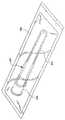
動作可能な注射針引込用アッセンブリを製造する方法は、細長い注射針用遮蔽体279を用意し、針状カニューレの末端部が注射針用遮蔽体内にあるように注射針用遮蔽体をアウタハブに取り外し可能に連結するステップをさらに含むことが好ましい。その際、注射針引込用アッセンブリは、微生物のバリアとして機能する包装体288に封止されてもよく、また、放射線滅菌、オートクレーブ消毒などのような方法を使って包装体とともに殺菌消毒されても良い。
【0036】
注射針引込用アッセンブリを製造する方法は、また、アウタハブ253がカラー31に係合するように、部屋27を形成している内面25と、開口した基端部28及び円筒状カラ―31を含んでいる開口末端部29とを有するシリンジバレル22(図1−11参照)に注射針アッセンブリを、取り付けるステップを含んでいてもよい。その方法は、注射針引込用アッセンブリがシリンジ用バレルに取り付けられる前か後のどちらかで、プランジャ23を用意するステップをさらに含んでいても良い。このステップは、注射針引込用アッセンブリの取り付けの前に最初に行われることが好ましい。このステップは、前記シリンジバレルの内面と液密に係合して摺動/可能に配置されるプランジャ23を用意することを含んでいる。その際、注射針引込み式シリンジは、微生物のバリアとして機能する包装体289に封止されても良い。そして、注射針引込み式シリンジと一緒に包装体は、放射線滅菌、オートクレーブ消毒などのような方法を使用して殺菌消毒される。
【0037】
本発明に係る注射針引込用アッセンブリおよび注射針引込み式シリンジにおける多くの構造的および機能的な利点に加えて、本発明は、注射針アッセンブリの部品が組立てられた後、その引込み用アッセンブリに対し針状カニューレを組み付けることができることにより、従来技術を越えた重要な利点を提供し、それによって、組立て工程中、脆い注射針の先端を損傷させるいかなる可能性も大いに低減させる。
【図面の簡単な説明】
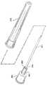
【図1】本発明の注射針引込用アッセンブリと注射針引込式シリンジの斜視図である。
【図2】取り替え可能なニードルアッセンブリを示す図1のシリンジである。
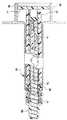
【図3】図1の線3−3に沿ったシリンジ及びニードルアッセンブリの断面図である。
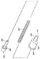
【図4】図1のシリンジ及びニードルアッセンブリの分解斜視図である。
【図5】注射針引込用アッセンブリのアウタハブの拡大断面図である。
【図6】注射針引込用アッセンブリのインナハブの拡大断面図である。
【図7】注射針引込用アッセンブリの拡大断面図である。
【図8】シリンジ用バレルの末端部の拡大断面図である。
【図9】その中に収容されている液体が送出された後にシリンジを示す図1のシリンジの末端部及び注射針引込用アッセンブリの断面図である。
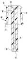
【図10】プランジャロッドの基端部分及び末端部分が分離し、解放要素がストッパ及びインナーハブ部分を貫通したとき、図9のシリンジを示す図である。
【図11】解放要素がインナーハブを完全に貫通し、注射針がプランジャ内に引込まれたときの図10のシリンジを示す図である。
【図12】本発明の注射針引込用アッセンブリ及びシリンジの別の実施例を示す図である。
【図13】本発明の注射針引込用アッセンブリを製造する方法を示す図である。
【図14】本発明の注射針引込用アッセンブリを製造する方法を示す図である。
【図15】本発明の注射針引込用アッセンブリを製造する方法を示す図である。
【図16】本発明の注射針引込用アッセンブリを製造する方法を示す図である。
【図17】本発明の注射針引込用アッセンブリを製造する方法を示す図である。
【符号の説明】
20 注射針引込式シリンジ
21、221 注射針引込用アッセンブリ
22、122 シリンジバレル
23 プランジャ
25、125 (バレルの)内面
27、127 部屋
28 (バレルの)基端部
29、129 (バレルの)末端部
30 (バレル末端部の)円錐表面
31、131 円筒状カラー
34、134 (カラーの)ネジ
35 (円筒状カラーの)テーパ状円筒表面
37 (プランジャの)基部
39 (プランジャの)細長い空洞部
43 解放要素
44 (解放要素の)鋭利な末端
46 (プランジャの)末端部分
47 (プランジャ末端部分の)末端部
50 栓体
51 (栓体の)円錐台表面
53、153、253 アウタハブ
57、257 通路
58 (通路の)ネジ
61、261 インナハブ
64 導管部
68 (内側ハブの)円錐台表面
71、271 針状カニューレ
73、273 (カニューレの)末端部
74、274 (カニューレの)基端部
76、276 圧縮コイルバネ
79、279 細長い注射針用遮蔽体[0001]
BACKGROUND OF THE INVENTION
The present invention relates to a syringe and a needle assembly. More particularly, the present invention relates to a syringe and needle assembly having a structure that allows for automatic retraction of a needle cannula into a syringe barrel after use, and a method of manufacturing the needle assembly.
[0002]
[Prior art]
In recent years, when disposing of used hypodermic syringes containing the product, there has been an increase in the transfer of diseases, infections, etc. to syringe users and medical professionals who pierce themselves by accidental or careless handling There was a problem going on. In many areas of hospitals where needle cannula products are used, disposal containers are provided. So the syringe or other needle cannula product is immediately discarded into a safe and rigid container. However, there are medical services such as emergency rooms where disposal containers are not readily available or practical, and products with self-contained safety features are desired. Theoretically, after such a syringe has been used for injecting a drug or for another purpose, a safety device housed in the syringe or needle assembly may provide further contact with the sharp needle tip. Operated to block. One type of secure syringe includes a structure that allows the hypodermic needle to be retracted into the syringe barrel to minimize further contact with the sharp needle tip.
[0003]
One prior art of such a needle retractable syringe includes a frangible region where the front wall of the barrel connected to the hypodermic needle can be separated from the side wall of the barrel. The syringe also allows the user to selectively attach the piston to the front wall so that the user can forcefully twist the piston, break the fragile structure, and retract the front wall containing the hypodermic needle into the syringe barrel. The structure is housed inside the front wall and outside the piston. This design requires a compromise in the design of the syringe barrel. The barrel must be strong enough to remain intact during normal use, but weak enough to be disconnected by any user regardless of force.
[0004]
The prior art also includes other needle retractable syringes. These syringes have a structure that engages the needle carrier so that the needle carrier can be forcibly removed from the syringe barrel by the action of the plunger rod and can be retracted into the syringe barrel. Many prior art syringe needle retractable syringes have similar deficiencies as the syringes described above. In particular, the needles or needle carriers of retractable syringes usually contain a highly viscous liquid, often with considerable fluid pressure experienced during injection and the force associated with penetrating the rubber stopper of the medicine bottle. During use, it must be held securely by the syringe barrel. The syringe barrel must hold the needle carrier to the extent that it can be removed by force applied to the plunger rod that extends from the open proximal end of the syringe barrel without being overwhelmed by the forces during normal use. I must. Many prior art designs of syringe retractable syringes that are made strong enough to withstand the forces during normal use have a needle carrier that cannot be easily removed. Also, easy removal of the injection needle or injection needle carrier may lead to a structure that cannot withstand the forces during normal use. This is especially true for needle carriers that are configured such that the needle assembly is removable so that the user can select the size of the hypodermic needle in use. These syringes must also withstand high torques and forces in attaching and removing needles. Furthermore, syringes that are retractable with a needle require a retraction procedure that is handled with both hands, which increases the difficulty in use.
[0005]
The prior art also includes a spring-loaded needle assembly that is held in place during normal use of the syringe assembly and sealed during normal use of the syringe assembly so that the drug does not enter the plunger rod cavity. A needle retractable syringe including a hollow plunger rod.
[0006]
These syringes have a structure that can release the spring loaded needle and the plunger rod cavity opening so that the syringe needle enters the plunger rod cavity after the syringe is used for its intended purpose. Must. Needle retractable syringes have the same design issues as the syringes described above with respect to syringe retractable syringes. In particular, the cavity of the plunger rod must be sealed so that the drug cannot enter the plunger rod during use. This seal must often withstand high fluid pressures when relatively viscous drugs are injected through a small needle. This seal must nevertheless be easily opened and can be inserted by means of a needle assembly. Furthermore, the needle assembly must be securely held in place by the force of the injection. And nevertheless, the needle assembly must be separable so that it can be retracted into the syringe barrel and into the plunger rod.
[0007]
Some prior art needle-retractable syringes use a plug that covers the cavity of the plunger rod that almost undoubtedly becomes difficult after the plug falls off during the injection process. In addition, some use plugs to hold the syringe assembly in place that is almost certainly out of use, which can cause concerns about the syringe during use. Furthermore, these designs do not take into account a replaceable needle assembly. Thus, these designs do not allow the health worker the freedom of any choice of injection needle, ie, the appropriate needle size for the procedure being performed. Furthermore, the need for a safe product such as a needle retractable syringe comes with the need for a product that is less expensive than a standard syringe assembly. The prior art of needle-retractable assemblies has drawbacks in that they present designs that cannot be made at a cost that allows their extensive use. This is because many designs require very close tolerances for reliability and require an assembly process that can damage the delicate tip of the needle cannula leading to high failure rates.
[0008]
[Problems to be solved by the invention]
The prior art suggests many different needle retractable syringes and needle retractable syringes that have the capacity to retract, i.e., the needle can enter a syringe barrel or plunger rod. However, the spring is nevertheless easily and intentionally released, while the needle assembly can enter the cavity of the plunger rod, while being simple, uncomplicated, reliable and easily assembled There is a need for a needle retractable syringe that is free of sufficient structural defects to withstand the forces of injection. There is also a need for a needle retractable syringe that has a replaceable spring-loaded needle assembly so that an appropriately sized syringe needle can be selected at the time of use, and to facilitate pre-filling . There is also a need for a needle retractable assembly that can be easily assembled in large quantities without damaging the delicate cutting edge of the needle cannula.
[0009]
[Means for Solving the Problems]
An operable needle retraction assembly for a syringe barrel comprising an inner surface forming a chamber, an open proximal end, an open distal end including a cylindrical collar, and a plunger having a release element having a sharp distal end. And an outer hub having a proximal end, a distal end, and a passage therein, and an inner hub having a proximal end, a distal end, and a conduit portion therein. The proximal end portion of the inner hub includes an inside and an externally connected and separable outside. The separable exterior of the inner hub is connected to the outer hub. The end portion of the inner hub is smaller than the passage of the outer hub at the end portion of the outer hub, and protrudes outward on the end side. The needle cannula has a distal end, a proximal end connected to the distal end of the inner hub, and a lumen therein. The connection is made such that the lumen is in fluid communication with the conduit. The biasing spring is accommodated between the outer hub and the inner hub. Connection means are provided for connecting the outer hub to the syringe barrel collar, such as screw engagement, gluing, ultrasonic welding and the like. The inner hub and the outer hub cut the part of the inner hub that separates the outside and the inside from which the sharp end of the release element can be separated by the movement of the end of the plunger having the release element having the sharp end in the barrel, and the spring The needle cannula is configured to move to the proximal end side.
[0010]
The operable needle retraction assembly further includes a syringe barrel having an interior surface defining a chamber, an open proximal end, and an open distal end including a cylindrical collar. The collar has an outer surface and an inner surface. The outer hub is connected to the collar so that the cannula projects distally outward from the syringe barrel.
[0011]
The plunger is slidably positioned in fluid tight engagement with the inner surface of the barrel. The plunger includes a base having a distal end with an elongated cavity therein, a release element having a sharp end positioned at the distal end of the base, and a hollow that is releasably connected to the base and is slidable relative to the base. And the end portion. A cover element seals the end of the end at the end of the end. The plunger base is moved while the base is moved distally so that the distal movement of the plunger relative to the barrel causes the release element to contact and advance through the cover element and inner hub to separate the separable exterior from the interior. So that the spring can move the needle cannula far enough into the base cavity so that the distal end of the cannula is positioned proximal to the distal end of the outer hub. The base part and the terminal part are connected.
[0012]
Another aspect of the present invention is a method of manufacturing an operable needle retraction assembly, the step of providing an outer hub having a proximal end, a distal end and a passage therethrough, a proximal end, a distal end, and Providing an inner hub having a conduit portion therethrough, providing a needle cannula having a distal end, a proximal end and a lumen therethrough, providing a compression coil spring, and a distal end of the inner hub The inner hub, the spring and the outer hub are assembled so that the spring is compressed and held in the outer hub by connecting the inner hub to the outer hub so that the portion reaches from the passage at the distal end of the outer hub; Place the end at the distal end of the inner hub conduit section and apply an adhesive to the space between the conduit section and the needle cannula. And a step of.
[0013]
DETAILED DESCRIPTION OF THE INVENTION
While this invention is to be construed by way of examples in many different forms, this disclosure is to be considered as an example of the spirit of this invention and limits the scope of the invention to the described embodiments. Knowing that is not intended to do, a preferred embodiment of the present invention will be shown in the drawings and will be described in detail herein. The scope of the invention will be measured by the appended claims and their equivalents.
[0014]
Referring to FIGS. 1 to 11, an operable needle
[0015]
The plunger is fluidly engaged with the inner surface of the barrel so as to be slidable. The plunger includes a base 37 having an
[0016]
The
[0017]
The needle retracting assembly also includes an
[0018]
[0019]
A biasing spring is accommodated between the outer hub and the inner hub. In this preferred embodiment, the biasing spring is a
[0020]
During assembly, the coil spring is placed over the entire inner portion of the inner hub, then the end of the spring is positioned within the outer hub, and the inner hub and outer hub are moved toward each other to compress the spring and the inner hub Are combined together by the action of the annular fixing
[0021]
The needle retraction assembly also includes means for connecting the outer hub to the collar of the syringe barrel. In this preferred embodiment, the connecting means includes a structure for threaded engagement between the collar and the outer hub. In this preferred embodiment, the screw engagement structure includes at least one
[0022]
Another important feature of the present invention results in a syringe for retracting a needle with less dead space. This means that almost all of the drug in the room is expelled from the syringe during the injection process. Many retractable and needle retractable syringe prior art has structures that protrude into the chamber to hold and / or release the retractable or retractable needle. Many medications surrounding these structures will be wasted and will not be delivered as the needle begins to retract while the medication is still in the barrel. In order to minimize drug loss for a needle retractable syringe having a structure protruding into the room, the user may begin the needle retraction procedure while the needle is still in the patient. The needle further exits the patient while the medication is being delivered. Also, as a result of the force applied to initiate the needle retraction procedure, the patient may be injured if the needle is moved sideways.
[0023]
In order to take full advantage of the low dead space feature of the present invention, the preferred embodiment includes a
[0024]
A variety of screw engagement structures between the collar and the outer hub include threads on the outer surface of the collar and screw followers on the inner surface of the outer hub that follow the threads of the collar when the hub is screwed into the collar. Screw-like and bayonet type structures. This structure is similar to a known fixed luer type needle assembly and syringe assembly, the collar of the syringe has a screw on its inner surface, and the needle assembly has a luer tip and collar. When screwed into the hub, it has two outwardly facing projections on the hub base to cause the hub to follow the collar threads. Further, the inner side of the collar is threaded on the outer side of the outer hub having a screw follower.
[0025]
One problem that has not been well discussed by the prior art is leakage. During use, the contents of the syringe are exposed to high pressures, both positive and negative, when attempting to inhale and deliver the drug, particularly viscous drugs. Preferably, in order to help prevent leakage without the need to use a gasket, the preferred embodiment tapers on the inner surface of the
[0026]
The present invention provides distinct developments and improvements over the prior art by proposing features such as leakage prevention and reduced dead space without the use of gaskets in combination with a removable needle retraction assembly.
[0027]
The
[0028]
In use, the needle retraction assembly of the present invention can be removably coupled to the
[0029]
Another feature of the barrel and plunger of the syringe of the present invention is that when the plunger reaches its furthest distal position with respect to the barrel, the
[0030]
In this preferred embodiment, the releasable connection between the
[0031]
FIG. 12 shows another embodiment of the present invention that functions similarly to the embodiment shown in FIGS. 1-11 except for the means for connecting the outer hub to the collar. In particular, the
[0032]
It is also within the scope of the present invention to include means for coupling the outer hub, which is fixedly engageable rather than removable, to the collar. For example, the outer hub may be attached to the collar using an adhesive or ultrasonic weld, retaining clip or one-way snap fit device that prevents the assembly from changing during normal use. Such a structure is within the scope of the present invention.
[0033]
Referring to FIGS. 13-17, another form of the invention includes a method of manufacturing an operable needle retraction assembly. Many of the prior art of needle retractable syringes require a syringe needle that is first assembled to the needle hub for its manufacture, and then the needle assembly including the needle and hub is located above the needle. By placing the outer hub over the sharp tip of the syringe needle, there is a significant drawback in that it is coupled to the spring and outer hub or similar structure. This is a difficult task because it is likely to damage the fragile, sharp end of the needle cannula and is almost impossible under mass production. As a result, this design is prohibitively expensive to manufacture in a mass production situation or is inappropriate for those purposes, ie at least very painful for the patient to accept This will result in an inadequate level of damaged needle. A significant improvement brought about by the present invention is to overcome the aforementioned disadvantages of prior art needle retractable syringes and retractable needles. The present invention allows assembly of the inner hub, outer hub and spring prior to attachment and coupling of the sharpened needle cannula. This means that the needle retraction assembly of the present invention can be manufactured in the same way as a conventional needle assembly, in which case the needle is further assembled except for the step of adding a needle shield. The steps are attached to a completed hub with nothing.
[0034]
The method of making the
[0035]
A method of manufacturing an operable needle retraction assembly includes providing an
[0036]
The method of manufacturing the needle retraction assembly also includes an
[0037]
In addition to the many structural and functional advantages of the needle retraction assembly and needle retractable syringe according to the present invention, the present invention provides for the retraction assembly after the parts of the needle assembly have been assembled. The ability to assemble a needle cannula provides significant advantages over the prior art, thereby greatly reducing any possibility of damaging the fragile needle tip during the assembly process.
[Brief description of the drawings]
FIG. 1 is a perspective view of a needle retraction assembly and a needle retraction syringe of the present invention.
2 is the syringe of FIG. 1 showing a replaceable needle assembly. FIG.
FIG. 3 is a cross-sectional view of the syringe and needle assembly taken along line 3-3 of FIG.
4 is an exploded perspective view of the syringe and needle assembly of FIG. 1. FIG.
FIG. 5 is an enlarged cross-sectional view of an outer hub of a needle retraction assembly.
FIG. 6 is an enlarged cross-sectional view of an inner hub of the needle retraction assembly.
FIG. 7 is an enlarged cross-sectional view of an injection needle retracting assembly.
FIG. 8 is an enlarged cross-sectional view of a distal end portion of a syringe barrel.
9 is a cross-sectional view of the distal end of the syringe of FIG. 1 and the needle retraction assembly showing the syringe after the liquid contained therein has been delivered.
10 shows the syringe of FIG. 9 when the proximal and distal portions of the plunger rod are separated and the release element has penetrated the stopper and inner hub portion.
11 shows the syringe of FIG. 10 when the release element has completely penetrated the inner hub and the injection needle has been retracted into the plunger.
FIG. 12 is a view showing another embodiment of the needle retraction assembly and syringe according to the present invention.
FIG. 13 is a view showing a method of manufacturing the needle retraction assembly according to the present invention.
FIG. 14 is a view showing a method of manufacturing the needle retraction assembly according to the present invention.
FIG. 15 is a view showing a method of manufacturing the needle retraction assembly of the present invention.
FIG. 16 is a view showing a method for producing the needle retraction assembly of the present invention.
FIG. 17 is a view showing a method of manufacturing the needle retraction assembly of the present invention.
[Explanation of symbols]
20 Injection needle retractable syringe
21, 221 Assembly for retracting needle
22, 122 Syringe barrel
23 Plunger
25, 125 (inside of the barrel)
27, 127 rooms
28 Base end (of barrel)
29, 129 (end of barrel)
30 Conical surface (at the end of the barrel)
31, 131 Cylindrical collar
34, 134 (color) screws
35 Tapered cylindrical surface (with cylindrical collar)
37 Base (of plunger)
39 Slender cavity (of the plunger)
43 Release elements
44 Sharp end (of release element)
46 End portion of plunger
47 End (of plunger end)
50 plug body
51 The surface of the truncated cone
53, 153, 253 Outer hub
57, 257 passage
58 (passage) screw
61,261 inner hub
64 Conduit section
68 Frustum surface (of inner hub)
71,271 needle cannula
73, 273 (of the cannula)
74,274 proximal end (of cannula)
76, 276 Compression coil spring
79,279 Shield for elongated needle
Claims (8)
Translated fromJapanese部屋を形成する内面(25)と、開口基端部(28)と、円筒状カラー(31)を含む開口末端部(29)とを有するシリンジバレル(22)と、
基端部(55)と、末端部(56)と、その中の通路(57)とを有するアウタハブ(53)と、
基端部(62)と、末端部(63)と、その中の導管部(64)とを有するインナハブ(61)であり、該基端部が内部(65)と、該内部に連結され前記アウタハブ(53)に連結される分離可能な外部(67)とを有し、該インナハブ(61)の末端部(63)が前記アウタハブ(53)の末端部(56)で前記アウタハブ(53)の通路(57)に比して小であり、末端側外方に突出するインナハブ(61)と、
末端部(73)と、基端部(74)と、その中の内腔(75)とを有する針状カニューレ(71)であり、該内腔(75)が前記導管部(64)に流体で連通するように該基端部(74)が前記インナハブ(61)の末端部(63)に連結される針状カニューレ(71)と、
前記バレル(22)の前記内面(25)に液密に係合して摺動可能に位置付けられるプランジャ(23)であって、細長い空洞部(39)を内部に備える末端部(38)を有する基部(37)と、該基部(37)の該末端部(38)に位置付けられ鋭利な末端部(44)を有する解放要素(43)と、前記基部(37)に解放可能に連結され該基部(37)に対し滑り出し可能とされる中空末端部(46)と、前記末端部(46)の末端(47)において該末端部(46)の末端(47)をシールするカバー要素(50)と、を含むプランジャ(23)と、
前記アウタハブ(53)と前記インナハブ(61)との間に収容される付勢バネ(76)と、
前記アウタハブ(53)を前記シリンジバレル(22)のカラー(31)に連結する連結手段(34,58)と、を備え、
前記バレル(22)内における鋭利な末端(44)を有する解放要素(43)を有するプランジャ(23)の末端(38)の動きにより、該解放要素(43)の鋭利な末端(44)が接触し、前記カバー要素(50)および前記インナハブ(61)を貫通し、前記分離可能な外部(67)と前記内部(65)とを分離する前記インナハブ(61)の一部分を切断し、前記バネ(76)が前記針状カニューレ(71)を基端方向に移動させることができるように、該プランジャ(23)の該基部(37)が該プランジャ(23)の該末端部(46)から離隔し、該基部(37)が末端方向に移動できる注射針引込み用アッセンブリ。Abehavior can needle retracting assembly (21),
A syringe barrel (22) having an inner surface (25) forming a chamber, an open proximal end (28), and an open distal end (29) including a cylindrical collar (31);
An outer hub (53) having a proximal end (55), a distal end (56), and a passage (57) therein;
An inner hub (61) having a proximal end portion (62), a distal end portion (63), and a conduit portion (64) therein, the proximal end portion being connected to the interior (65) andthe interior; A separable outer part (67) connected to the outer hub (53), andthe end part (63)of the inner hub (61 ) is the end part (56) of the outer hub (53). An inner hub (61) which is smaller than the passage (57) and projects outwardly on the end side;
A needle cannula (71) having a distal end (73), a proximal end (74), and a lumen (75) therein, the lumen (75) being fluid to the conduit (64) A needle cannula (71) whose proximal end (74) is connected to the distal end (63) of the inner hub (61) so as to communicate with each other;
A plunger (23) slidably positioned in fluid tight engagement with the inner surface (25) of the barrel (22), having a distal end (38) with an elongated cavity (39) therein A base (37), a release element (43) positioned at the end (38) of the base (37) and having a sharp end (44), and releasably connected to the base (37) A hollow end (46) that is slidable relative to (37), and a cover element (50) that seals the end (47) of the end (46) at the end (47) of the end (46). A plunger (23) comprising
A biasing spring (76) received between the outer hub (53) and the inner hub (61);
Connecting means (34, 58) for connecting the outer hub (53) to the collar (31) of the syringe barrel (22);
Movement of the distal end (38) of the plunger (23) with the release element (43) having a sharp end (44) within the barrel (22) causes the sharp end (44) of the release element (43) tocontact. A portion of the inner hub (61) that passes through the cover element (50) and the inner hub (61) and separates the separable outer portion (67) and the inner portion (65); 76)separates the base (37) of the plunger (23) from the distal end (46) of the plunger (23)so that theneedle cannula (71) can be moved proximally.A needle retraction assembly in which thebase (37) can move in the distal direction .
Applications Claiming Priority (2)
| Application Number | Priority Date | Filing Date | Title |
|---|---|---|---|
| US09/419,184US6368303B1 (en) | 1999-10-15 | 1999-10-15 | Retracting needle syringe |
| US09/419184 | 1999-10-15 |
Publications (3)
| Publication Number | Publication Date |
|---|---|
| JP2001161817A JP2001161817A (en) | 2001-06-19 |
| JP2001161817A5 JP2001161817A5 (en) | 2007-11-29 |
| JP4312368B2true JP4312368B2 (en) | 2009-08-12 |
Family
ID=23661160
Family Applications (1)
| Application Number | Title | Priority Date | Filing Date |
|---|---|---|---|
| JP2000315936AExpired - LifetimeJP4312368B2 (en) | 1999-10-15 | 2000-10-16 | Injection needle retractable syringe |
Country Status (13)
| Country | Link |
|---|---|
| US (2) | US6368303B1 (en) |
| EP (2) | EP1323447B1 (en) |
| JP (1) | JP4312368B2 (en) |
| CN (1) | CN1243575C (en) |
| AT (2) | ATE327791T1 (en) |
| AU (1) | AU779820B2 (en) |
| BR (1) | BR0004721B1 (en) |
| CA (1) | CA2316064C (en) |
| DE (2) | DE60028423T2 (en) |
| DK (2) | DK1323447T3 (en) |
| ES (2) | ES2243179T3 (en) |
| MX (1) | MXPA00010073A (en) |
| NZ (1) | NZ506456A (en) |
Families Citing this family (136)
| Publication number | Priority date | Publication date | Assignee | Title |
|---|---|---|---|---|
| US6843781B2 (en)* | 1999-10-14 | 2005-01-18 | Becton, Dickinson And Company | Intradermal needle |
| US8226617B2 (en) | 1999-11-04 | 2012-07-24 | Tyco Healthcare Group Lp | Safety shield apparatus and mounting structure for use with medical needle devices |
| US6280420B1 (en) | 1999-11-04 | 2001-08-28 | Specialized Health Products | Reaccessible medical needle safety devices and methods |
| US7029461B2 (en) | 1999-11-04 | 2006-04-18 | Tyco Healthcare Group Lp | Safety shield for medical needles |
| US7198618B2 (en) | 1999-11-04 | 2007-04-03 | Tyco Healthcare Group Lp | Safety shield for medical needles |
| PT1607115E (en) | 1999-11-18 | 2009-11-30 | Tyco Healthcare | Safety needle autosheath |
| US20030050605A1 (en)* | 1999-12-08 | 2003-03-13 | John Targell | Closure assembly in particular for hypodermic syringes |
| OA11679A (en)* | 2000-01-26 | 2005-01-12 | Tecnedil Srl | Improved disposable syringe with a retractable needle. |
| US6475194B2 (en)* | 2000-04-05 | 2002-11-05 | Gem Plastics, Inc. | Safety syringe |
| US6592555B1 (en)* | 2000-06-23 | 2003-07-15 | Wang Wen-Pi | Syringe device |
| US6599268B1 (en)* | 2000-06-27 | 2003-07-29 | Becton Dickinson And Company | Hypodermic syringe with a selectively retractable needle |
| US6585690B1 (en)* | 2000-06-29 | 2003-07-01 | Becton Dickinson And Company | Hypodermic syringe with selectivity retractable needle |
| US6689106B2 (en)* | 2000-07-31 | 2004-02-10 | Becton Dickinson And Company | Retracting needle assembly for a syringe |
| US6413237B1 (en) | 2000-08-31 | 2002-07-02 | Becton, Dickinson And Company | Hypodermic syringe with selectively retractable needle |
| US6511459B1 (en)* | 2000-09-29 | 2003-01-28 | Mallinckrodt Inc. | Syringe plunger having an improved sealing ability |
| US7544189B2 (en)* | 2000-10-10 | 2009-06-09 | Meridian Medical Technologies, Inc. | Needle and hub assembly for automatic injector |
| US7621887B2 (en)* | 2000-10-10 | 2009-11-24 | Meridian Medical Technologies, Inc. | Wet/dry automatic injector assembly |
| AUPR131000A0 (en)* | 2000-11-09 | 2000-11-30 | Southern Dental Industries Limited | A dental cartridge |
| WO2002070056A1 (en) | 2001-03-02 | 2002-09-12 | Sherwood Services Ag | Passive safety shield |
| AUPR373001A0 (en)* | 2001-03-14 | 2001-04-12 | Glenord Pty Ltd | Improved non-reusable syringe |
| US7144389B2 (en) | 2001-03-14 | 2006-12-05 | Tyco Healthcare Group, Lp | Safety shield for medical needles |
| US6800066B2 (en) | 2001-04-26 | 2004-10-05 | Nmt Group Plc | Retractable needle syringe |
| AU2002223385B2 (en)* | 2001-07-20 | 2007-01-25 | Medicalchain International Corp. | An automatically retractable safety syringe |
| US20030040720A1 (en)* | 2001-08-22 | 2003-02-27 | Steube Gregory Alan | Needle hub assembly |
| US6835190B2 (en)* | 2002-04-17 | 2004-12-28 | Smiths Medical Asd, Inc. | Retractable safety infusion needle |
| WO2004004812A1 (en)* | 2002-07-03 | 2004-01-15 | Novo Nordisk A/S | A needle mounting system and a method for mounting a needle assembly |
| US7654986B2 (en) | 2002-07-03 | 2010-02-02 | Novo Nordisk A/S | Needle mounting system and a method for mounting a needle assembly |
| US7553296B2 (en) | 2003-02-14 | 2009-06-30 | Tyco Healthcare Group Lp | Safety device with trigger mechanism |
| GB2398248A (en) | 2003-02-14 | 2004-08-18 | Scient Generics Ltd | Safety device with trigger mechanism |
| US6905485B2 (en)* | 2003-02-19 | 2005-06-14 | Becton, Dickinson And Company | Medical device with needle safety shielding |
| US20040176705A1 (en)* | 2003-03-04 | 2004-09-09 | Stevens Timothy A. | Cartridge having an integrated collection element for point of care system |
| US20040176704A1 (en)* | 2003-03-04 | 2004-09-09 | Stevens Timothy A | Collection device adapted to accept cartridge for point of care system |
| EP1615683A1 (en)* | 2003-04-16 | 2006-01-18 | Mallinckrodt Inc. | Radiation shield for a safety syringe having a needle sheath |
| JP4289919B2 (en)* | 2003-05-06 | 2009-07-01 | 朝日インテック株式会社 | Chemical injection device |
| US7037292B2 (en)* | 2003-06-27 | 2006-05-02 | Sherwood Services Ag | Safety needle shield apparatus |
| IL157981A (en) | 2003-09-17 | 2014-01-30 | Elcam Medical Agricultural Cooperative Ass Ltd | Auto-injector |
| IL157984A (en) | 2003-09-17 | 2015-02-26 | Dali Medical Devices Ltd | Autoneedle |
| GB2410188B (en)* | 2004-01-23 | 2006-01-25 | Medical House Plc | Injection device |
| GB2410190A (en)* | 2004-01-26 | 2005-07-27 | Medical House Plc | Disposable gas-powered needle-free injection device |
| EP1708772B1 (en)* | 2004-01-28 | 2012-06-20 | Unitract Syringe Pty Ltd | Retractable syringe with plunger disabling system |
| IL160891A0 (en) | 2004-03-16 | 2004-08-31 | Auto-mix needle | |
| SE0401569D0 (en)* | 2004-06-17 | 2004-06-17 | Gambro Lundia Ab | applicator |
| AU2005272621B2 (en)* | 2004-08-13 | 2010-11-11 | Becton, Dickinson And Company | Retractable needle syringe assembly |
| ES2427631T3 (en)* | 2004-10-14 | 2013-10-31 | Midland Medical Devices Holdings, Llc | Medical safety syringe with retractable needle |
| WO2006111806A2 (en)* | 2005-02-07 | 2006-10-26 | Indigo Orb, Inc. | Safety syringes |
| US8062252B2 (en)* | 2005-02-18 | 2011-11-22 | Becton, Dickinson And Company | Safety shield system for a syringe |
| JP4622876B2 (en)* | 2005-03-24 | 2011-02-02 | 株式会社ジェイ・エム・エス | Indwelling needle device |
| US7740636B2 (en)* | 2005-04-15 | 2010-06-22 | Abbott Medical Optics Inc. | Multi-action device for inserting an intraocular lens into an eye |
| CN100544784C (en)* | 2005-04-26 | 2009-09-30 | 刘文杰 | Barrel push rod of needle retractable syringe and syringe with controllable needle retraction |
| US7947020B2 (en)* | 2005-05-09 | 2011-05-24 | Safeshot Technologies, Llc | Retractable safety syringe |
| US20060264840A1 (en)* | 2005-05-09 | 2006-11-23 | Daniel Thayer | Syringe |
| GB0601309D0 (en) | 2006-01-23 | 2006-03-01 | Medical House The Plc | Injection device |
| US20070173770A1 (en)* | 2006-01-23 | 2007-07-26 | The Medical House Plc | Injection device |
| TWI294782B (en)* | 2006-01-27 | 2008-03-21 | Bencha Internat Group Inc | Medically safety injector with a collapsable plunger combination thereof |
| CA2645485A1 (en) | 2006-03-21 | 2007-09-27 | Tyco Healthcare Group Lp | Passive latch ring safety shield for injection devices |
| US7972301B2 (en) | 2006-04-03 | 2011-07-05 | Safeshot Technologies, Llc | Safety needle syringe braking system |
| US20070250003A1 (en)* | 2006-04-03 | 2007-10-25 | Bare Rex O | Fluid activated retractable safety syringe |
| CN100408120C (en)* | 2006-04-05 | 2008-08-06 | 刘文杰 | Changeable needle structure of needle retraction type injector, and said injector |
| US7806858B2 (en)* | 2006-04-19 | 2010-10-05 | Safeshot Technologies, Llc | Vacuum actuated small volume syringe |
| US8152762B2 (en)* | 2006-04-20 | 2012-04-10 | Safeshot Technologies, Llc | Plunger activated vacuum release mechanism for a syringe |
| US8398601B2 (en)* | 2006-11-06 | 2013-03-19 | Safeshot Technologies, Llc | Puncturable membrane for safety syringe |
| US20080097306A1 (en)* | 2006-08-29 | 2008-04-24 | Jeffrey Smith | Sterilized syringe |
| US20080114307A1 (en)* | 2006-11-06 | 2008-05-15 | Jeffrey Smith | Puncturable membrane for safety syringe |
| US7972300B2 (en)* | 2006-05-05 | 2011-07-05 | Safeshot Technologies, Llc | Syringe |
| US8088104B2 (en)* | 2006-05-24 | 2012-01-03 | Safeshot Technologies, Llc | Syringe |
| US20080033347A1 (en)* | 2006-08-03 | 2008-02-07 | Becton, Dickinson And Company | Detachable needle syringe having reduced dead space |
| US20080033370A1 (en) | 2006-08-03 | 2008-02-07 | Becton, Dickinson And Company | Binary needle attachment mechanisms |
| ITMI20062190A1 (en) | 2006-11-15 | 2008-05-16 | Amendola Carlo | DISPOSABLE SYRINGE OF PERFECT TYPE |
| US7637889B2 (en)* | 2006-11-15 | 2009-12-29 | Glynntech, Inc. | Drug delivery device with sliding valve and methodology |
| US8088110B2 (en)* | 2006-11-17 | 2012-01-03 | Bencha International Group Inc. | Automatically retractable safety injector for non-liquid material |
| US8382713B2 (en)* | 2006-12-11 | 2013-02-26 | Kenergy Scientific, Inc. | Drug delivery device and methodology |
| GB0625169D0 (en) | 2006-12-18 | 2007-01-24 | Medical House Plc The | Improved autoinjector |
| US20080154212A1 (en)* | 2006-12-26 | 2008-06-26 | Stat Medical Devices, Inc. | Syringe with retractable needle support |
| GB0704351D0 (en) | 2007-03-07 | 2007-04-11 | Medical House Plc The | Improved autoinjector |
| JP5362591B2 (en)* | 2007-03-09 | 2013-12-11 | イーライ リリー アンド カンパニー | Delay mechanism for automatic injection equipment |
| US8095870B2 (en)* | 2007-06-06 | 2012-01-10 | Oracle International Corporation | Extensible document transformation language: an innovative way of generating business document and report |
| USD675316S1 (en)* | 2007-08-22 | 2013-01-29 | Novo Nordisk A/S | Needle hub |
| GB0721774D0 (en)* | 2007-11-07 | 2007-12-19 | 3M Innovative Properties Co | one-piece vented piston |
| US7976510B2 (en) | 2008-02-28 | 2011-07-12 | Becton, Dickinson And Company | Syringe with adjustable two piece plunger rod |
| US8172813B2 (en)* | 2008-02-28 | 2012-05-08 | Becton, Dickinson And Company | Syringe with two piece plunger rod |
| CA2723694C (en)* | 2008-05-08 | 2014-03-25 | Shantou Wealy Medical Instrument Co., Ltd. | A disposable self-destruction safety syringe without fluid residua |
| US7785296B2 (en) | 2008-07-17 | 2010-08-31 | Smiths Medical Asd, Inc. | Needle tip spring protector |
| CN101480511B (en)* | 2009-02-08 | 2011-10-05 | 浙江康康医疗器械有限公司 | Disposable safety syringe with syringe needle capable of automatically retracting |
| US9480799B2 (en)* | 2009-04-08 | 2016-11-01 | Stat Medical Devices, Inc. | Retractable needle assembly utilizing a standard interface and syringe utilizing the same |
| US8986249B2 (en)* | 2009-04-08 | 2015-03-24 | Stat Medical Devices, Inc. | Retractable needle assembly and syringe utilizing the same |
| US20110125130A1 (en)* | 2009-04-08 | 2011-05-26 | Stat Medical Devices, Inc. | Retractable needle assembly and syringe utilizing the same |
| GB2469672B (en) | 2009-04-23 | 2013-09-25 | Medical House Ltd | Improved autoinjector |
| USD621036S1 (en)* | 2009-08-04 | 2010-08-03 | 3M Innovative Properties Company | Grooved piston |
| USD621039S1 (en)* | 2009-08-04 | 2010-08-03 | 3M Innovative Properties Company | Grooved piston |
| USD621038S1 (en)* | 2009-08-04 | 2010-08-03 | 3M Innovative Properties Company | Grooved piston |
| USD621930S1 (en)* | 2009-08-04 | 2010-08-17 | 3M Innovative Properties Company | Grooved piston |
| WO2011017181A1 (en) | 2009-08-04 | 2011-02-10 | 3M Innovative Properties Company | Dispensing device with pressure release |
| USD621037S1 (en)* | 2009-08-04 | 2010-08-03 | 3M Innovative Properties Company | Grooved piston |
| JP2011136151A (en)* | 2009-10-19 | 2011-07-14 | Terumo Medical Corp | Syringe assembly having detachable needle assembly and low dead space |
| USD632784S1 (en)* | 2010-01-14 | 2011-02-15 | Sumitomo Rubber Industries, Ltd. | Gasket for injector |
| USD632389S1 (en)* | 2010-01-14 | 2011-02-08 | Sumitomo Rubber Industries, Ltd. | Gasket for injector |
| USD633202S1 (en)* | 2010-01-14 | 2011-02-22 | Sumitomo Rubber Industries, Ltd. | Gasket for injector |
| USD657876S1 (en) | 2010-02-02 | 2012-04-17 | 3M Innovative Properties Company | Dental capsule |
| ES2484266T3 (en) | 2010-03-01 | 2014-08-11 | Eli Lilly And Company | Automatic injection device with delay mechanism including a double function thrust element |
| RU2534405C2 (en) | 2010-05-07 | 2014-11-27 | Интьюитив Криэйшнс Пте. Лтд. | Syringe with retractable needle and cutting crown |
| US9320856B2 (en) | 2010-05-07 | 2016-04-26 | Intuitive Creations Pte. Ltd. | Syringe assembly and a needle unit for attachment to a syringe unit to form a syringe assembly |
| US8333737B2 (en) | 2010-06-03 | 2012-12-18 | Jms North America Corporation | Systems and methods for a medical syringe |
| US8556855B2 (en) | 2010-07-22 | 2013-10-15 | Becton, Dickinson And Company | Dual chamber syringe with retractable needle |
| US8721599B2 (en) | 2010-07-22 | 2014-05-13 | Becton, Dickinson And Company | Dual chamber passive retraction needle syringe |
| US8556854B2 (en) | 2010-07-22 | 2013-10-15 | Becton, Dickinson And Company | Dual chamber syringe with retractable needle |
| US9550030B2 (en) | 2010-07-22 | 2017-01-24 | Becton, Dickinson And Company | Dual chamber syringe with retractable needle |
| US8277422B2 (en) | 2010-07-23 | 2012-10-02 | Safeshot Technologies, Llc | Multi-chambered retractable safety syringe |
| EP2585145B1 (en) | 2010-08-19 | 2014-03-05 | West Pharmaceutical Services, Inc. | Rigid needle shield |
| USD665498S1 (en)* | 2011-01-11 | 2012-08-14 | Fuso Pharmaceutical Industries, Ltd. | Gasket for injector |
| ES2710905T3 (en) | 2011-01-24 | 2019-04-29 | E3D Agricultural Coop Association Ltd | Injector |
| US8657793B2 (en) | 2011-09-30 | 2014-02-25 | Becton Dickinson France, S.A.S | Space saving plunger cap and rod assembly |
| CA2854003C (en) | 2011-11-07 | 2020-07-14 | Safety Syringes, Inc. | Contact trigger release needle guard |
| US8784376B2 (en) | 2012-12-04 | 2014-07-22 | Becton, Dickinson And Company | Thumb press frangible feature for re-use prevention |
| US10780229B2 (en) | 2013-03-07 | 2020-09-22 | David B. Brothers | Low waste syringe and needle assemblage |
| JP2016508853A (en)* | 2013-03-07 | 2016-03-24 | デイヴィッド ビー. ブラザーズ、 | Minimized syringe and needle assembly |
| MX2015013058A (en) | 2013-03-14 | 2016-05-31 | Lilly Co Eli | Trigger assembly for an automatic injection device. |
| KR20150119092A (en) | 2013-03-14 | 2015-10-23 | 일라이 릴리 앤드 캄파니 | Delay mechanism suitable for compact automatic injection device |
| WO2014179599A1 (en)* | 2013-05-03 | 2014-11-06 | Chen Rayfu | Auto-retractable safety syringe |
| EP3043831A1 (en)* | 2013-09-09 | 2016-07-20 | Covidien LP | Single-use device for injection of cartridge drugs |
| EP3043830A1 (en) | 2013-09-09 | 2016-07-20 | Covidien LP | Sealed self-activating injecton device for delivery of medicine from a prefilled cartridge or vial |
| US9937299B2 (en) | 2013-09-26 | 2018-04-10 | Becton, Dickinson And Company | Adjustable penetration depth syringe |
| US9078977B2 (en) | 2013-09-30 | 2015-07-14 | Becton, Dickinson And Company | Dual shielded syringe |
| USD747797S1 (en) | 2013-11-14 | 2016-01-19 | Eli Lilly And Company | Injection device |
| GB2522656A (en)* | 2014-01-31 | 2015-08-05 | Consort Medical Plc | Improved syringe for autoinjector device |
| US9555221B2 (en) | 2014-04-10 | 2017-01-31 | Smiths Medical Asd, Inc. | Constant force hold tip protector for a safety catheter |
| USD814630S1 (en)* | 2014-09-09 | 2018-04-03 | Covidien Lp | Syringe |
| CA3009221A1 (en) | 2014-12-23 | 2016-06-30 | Automed Pty Ltd | Delivery apparatus, system and associated methods |
| JP6635698B2 (en)* | 2015-07-14 | 2020-01-29 | ぺんてる株式会社 | Applicator with limited plunger movable range by resistance structure |
| USD823460S1 (en)* | 2015-12-08 | 2018-07-17 | Glenmark Pharmaceuticals S.A. | Anal device |
| KR102165159B1 (en)* | 2018-03-28 | 2020-11-04 | (주) 에스엔제이 | disposable safety syringe |
| EP3821925B1 (en)* | 2019-09-18 | 2024-03-20 | KAISHA PACKAGING Private Ltd. | Device for locking a plunger rod of a syringe after use and preventing re-use of the syringe, and syringe assembly |
| US20230086278A1 (en)* | 2020-02-14 | 2023-03-23 | Merck Sharp & Dohme Llc | Patient training device for use with a safety syringe injector |
| US11957542B2 (en) | 2020-04-30 | 2024-04-16 | Automed Patent Holdco, Llc | Sensing complete injection for animal injection device |
| CN111921040A (en)* | 2020-09-18 | 2020-11-13 | 中为(广东)医学科技有限公司 | Needle assembly and method |
| USD986413S1 (en) | 2021-07-23 | 2023-05-16 | Eli Lilly And Company | Drug delivery device |
| CA211897S (en)* | 2021-10-18 | 2024-03-04 | Tellgen Corp | Pcr tube assembly |
Family Cites Families (83)
| Publication number | Priority date | Publication date | Assignee | Title |
|---|---|---|---|---|
| IT1273192B (en) | 1994-05-10 | 1997-07-07 | Musetta Angela | DISPOSABLE SAFETY SYRINGE |
| US4233975A (en) | 1978-10-04 | 1980-11-18 | Yerman Arthur J | Anti-drug abuse single-use syringe |
| US4687467A (en) | 1986-06-11 | 1987-08-18 | C.T.F. Research Company | One-time use medical syringe invention |
| GB2197792A (en) | 1986-11-26 | 1988-06-02 | Power Richard Kiteley | Disposable syringes |
| US4927414A (en) | 1987-04-29 | 1990-05-22 | Kulli John C | Syringe with safety retracting needle |
| US4900307A (en) | 1987-04-29 | 1990-02-13 | Kulli John C | Safety retracting needle for use with syringe |
| IN169618B (en) | 1987-06-25 | 1991-11-23 | Agven Medical Corp Ltd | |
| US5011476A (en) | 1987-07-01 | 1991-04-30 | Foster Robert J C | Single fill and use syringe |
| DK156414C (en) | 1987-07-13 | 1990-01-22 | Gerda Ingrid Maria Gaarde | INJECTIVE SPRAY WITH CANNEL THAT CAN BE WITHDRAWED AND FIXED IN THE SPRAY |
| US4838869A (en) | 1987-08-29 | 1989-06-13 | Allard Edward F | Retractable needle syringe |
| US4838863A (en) | 1987-09-21 | 1989-06-13 | Allard Edward F | Safe needle system for collecting fluids |
| US4955870A (en) | 1988-08-23 | 1990-09-11 | Ridderheim Kristen A | Hypodermic syringe with retractable needle |
| US4929237A (en) | 1988-11-07 | 1990-05-29 | David Medway | Hypodermic needle protection device |
| US5013301A (en) | 1988-11-18 | 1991-05-07 | Marotta Jr Phillip | Syringe holder |
| IT1227658B (en) | 1988-12-01 | 1991-04-23 | Vittorio Boschetti B | DISPOSABLE SYRINGE WITH RETURN AND NEEDLE LOCK AT THE END OF INJECTION FOR THE PURPOSE OF AVOID RE-USE |
| IT1225440B (en) | 1988-12-07 | 1990-11-13 | Nacci Gaetano | PISTON FOR SYRINGES THAT AUTOMATICALLY MAKES THE HYPODERMIC NEEDLE, MODIFIED PURPOSE, AFTER USE |
| ES2019792A6 (en) | 1990-01-17 | 1991-07-01 | Caralt Batlle Jaime | Disposable hypodermic syringe. |
| ES2009709A6 (en) | 1989-01-24 | 1989-10-01 | Villar Pascual Jose Antonio | Single-use safety syringe |
| US4966593A (en) | 1989-03-06 | 1990-10-30 | Design Specialties Laboratories | Disposable hypodermic syringe with retractable needle |
| US5045063A (en) | 1989-05-30 | 1991-09-03 | Spielberg Alissa R | Hypodermic syringe |
| US4946446A (en) | 1989-06-14 | 1990-08-07 | Vadher Dinesh L | Retractable needle |
| US4994034A (en) | 1989-07-11 | 1991-02-19 | Botich Michael J | Retractable needle hypodermic syringe system |
| US5407431A (en) | 1989-07-11 | 1995-04-18 | Med-Design Inc. | Intravenous catheter insertion device with retractable needle |
| US6096005A (en)* | 1989-07-11 | 2000-08-01 | Mdc Investment Holdings, Inc. | Retractable needle medical devices |
| US5188599A (en) | 1989-07-11 | 1993-02-23 | Med-Design, Inc. | Retractable needle system |
| US5084018A (en) | 1989-08-14 | 1992-01-28 | Tsao Chien Hua | Safety syringe |
| US5019044A (en) | 1989-08-14 | 1991-05-28 | Tsao Chien Hua | Safety hypodermic syringe |
| US5046508A (en) | 1989-12-19 | 1991-09-10 | Jonathan Weissler | Syringe with retractable needle |
| US4973316A (en) | 1990-01-16 | 1990-11-27 | Dysarz Edward D | One handed retractable safety syringe |
| ES2074168T3 (en) | 1990-03-08 | 1995-09-01 | Blue Star Corp Sa | SELF-SWEEPING NEEDLE SYRINGE. |
| US5085640A (en) | 1990-04-06 | 1992-02-04 | Gibbs Andrew H | Non-reusable medical needle apparatus |
| US5053010A (en) | 1990-10-03 | 1991-10-01 | Triad Technology | Safety syringe with retractable needle |
| US5376080A (en) | 1991-01-30 | 1994-12-27 | Petrussa; Gian L. | Single use retractable needle syringe |
| US5092853A (en) | 1991-02-04 | 1992-03-03 | Couvertier Ii Douglas | Automatic retractable medical needle and method |
| US5267961A (en) | 1991-04-03 | 1993-12-07 | Shaw Thomas J | Nonreusable syringe with safety indicator |
| GB9107647D0 (en) | 1991-04-11 | 1991-05-29 | Jeffrey Peter | Syringe construction providing needle point protection |
| ES2067910T3 (en) | 1991-05-29 | 1995-04-01 | Paolo Caselli | SYRINGE PROVIDED WITH A SELF-LOCKING NEEDLE DEVICE AND MEANS TO OBTAIN THE RETURN OF THE NEEDLE IN THE SYRINGE AT THE END OF AN INJECTION. |
| ES1017717Y (en) | 1991-05-30 | 1993-12-16 | Serrano Gonzalez | SELF-RETRACTILE HYPODERMIC NEEDLE PROTECTOR. |
| US5232447A (en) | 1991-08-08 | 1993-08-03 | Jetfill, Inc. | Non-reusable syringe |
| US5211629A (en)* | 1991-12-23 | 1993-05-18 | Pressly William B S | Safety syringe |
| US5613952A (en) | 1991-12-23 | 1997-03-25 | Syringe Develpoment Partners | Safety syringe |
| US5180369A (en) | 1992-01-20 | 1993-01-19 | Dysarz Edward D | Self destructive safety syringe |
| US5188597A (en) | 1992-04-13 | 1993-02-23 | Becton, Dickinson And Company | Safety needle syringe |
| MX9302834A (en) | 1992-05-15 | 1993-11-01 | Safe T Ltd | HOLLOW NEEDLE APPLICATOR. |
| US5180370A (en) | 1992-05-18 | 1993-01-19 | Gillespie Elgene R | Safety hypodermic syringe with retractable needle |
| US5562629A (en) | 1993-08-31 | 1996-10-08 | Haughton; Victor M. | Catheter placement system utilizing a handle, a sharp, and a releasable retainer mechanism providing retraction of the sharp upon disengagement of the catheter from the handle |
| US5531694A (en) | 1993-08-31 | 1996-07-02 | Clemens; Anton H. | Needle retraction system |
| US5395337A (en) | 1993-08-31 | 1995-03-07 | Clemens; Anton H. | Needle retraction system |
| US5385551A (en) | 1993-09-22 | 1995-01-31 | Shaw; Thomas J. | Nonreusable medical device with front retraction |
| WO1995011713A1 (en) | 1993-10-28 | 1995-05-04 | Lok-Tek Syringe Pty Ltd | Hypodermic syringe with retractable needle mount |
| CA2135706C (en) | 1993-11-15 | 1999-06-15 | Walter E. Cover | Retractable-needle cannula insertion set with refinements to better control leakage, retraction speed, and reuse |
| US5634909A (en) | 1993-12-09 | 1997-06-03 | Schmitz; William L. | Auto-retracting needle injector system |
| US5423758A (en) | 1993-12-16 | 1995-06-13 | Shaw; Thomas J. | Retractable fluid collection device |
| US5573510A (en) | 1994-02-28 | 1996-11-12 | Isaacson; Dennis R. | Safety intravenous catheter assembly with automatically retractable needle |
| US5389076A (en) | 1994-04-05 | 1995-02-14 | Shaw; Thomas J. | Single use medical device with retraction mechanism |
| DE69505142T2 (en) | 1994-08-18 | 1999-05-12 | Nmt Group Plc, Bellshill, Lanarkshire | DEVICES FOR WITHDRAWAL OF NEEDLES |
| US5533970A (en) | 1994-09-28 | 1996-07-09 | Becton, Dickinson And Company | Retractable needle syringe |
| US5480385A (en) | 1995-01-10 | 1996-01-02 | Specialized Health Products, Inc. | Self retracting medical needle apparatus and methods |
| US5637092A (en) | 1995-01-30 | 1997-06-10 | Shaw; Thomas J. | Syringe plunger locking assembly |
| US6090077A (en)* | 1995-05-11 | 2000-07-18 | Shaw; Thomas J. | Syringe plunger assembly and barrel |
| US5632733A (en) | 1995-05-11 | 1997-05-27 | Shaw; Thomas J. | Tamperproof retractable syringe |
| US5578011A (en) | 1995-05-11 | 1996-11-26 | Shaw; Thomas J. | Tamperproof retractable syringe |
| US5685863A (en) | 1995-08-15 | 1997-11-11 | Mdc Investment Holdings Inc. | Retractable needle apparatus for transmission of intravenous fluids |
| AU6858396A (en) | 1995-08-22 | 1997-03-19 | Mdc Investment Holdings, Inc. | Pre-filled retractable needle injection ampoules |
| IT1279684B1 (en) | 1995-11-10 | 1997-12-16 | Claudio Freschi | SYRINGE FOR HYPODERMIC INJECTIONS. |
| US5605544A (en) | 1996-02-12 | 1997-02-25 | Tsao; Chien-Hua | Safety injector with returnable needle |
| US5643211A (en) | 1996-02-29 | 1997-07-01 | Medi-Ject Corporation | Nozzle assembly having a frangible plunger |
| US5665075A (en) | 1996-07-03 | 1997-09-09 | Becton, Dickinson And Company | Method of making a needle shield assembly |
| US5921961A (en) | 1996-09-13 | 1999-07-13 | Mcgary; R. Kern | Non-reusable retractable safety syringe |
| US5769822A (en)* | 1996-09-13 | 1998-06-23 | Mcgary; R. Kern | Non-reusable retractable safety syringe |
| US5681292A (en) | 1996-10-29 | 1997-10-28 | Retrax Safety Systems, Inc. | Retractable needle and syringe combination |
| US5782803A (en) | 1996-11-26 | 1998-07-21 | Jentzen; S. William | Low dead space, interchangeable needle syringe |
| US5800395A (en) | 1996-12-05 | 1998-09-01 | Mdc Investment Holdings, Inc. | Medical device with retractable needle |
| US6004278A (en) | 1996-12-05 | 1999-12-21 | Mdc Investment Holdings, Inc. | Fluid collection device with retractable needle |
| US5885257A (en) | 1997-03-18 | 1999-03-23 | Badger; Peter | Spring loaded automatic retractable needle syringe |
| US5882342A (en) | 1997-04-11 | 1999-03-16 | Safety Medical Manufacturing, Inc | Safety medical syringe with retractable needle |
| US5935104A (en) | 1998-08-21 | 1999-08-10 | Safety Medical Manufacturing, Incorporated | Safety medical syringe with retractable needle |
| AU1609500A (en)* | 1998-11-06 | 2000-05-29 | Mdc Investment Holdings, Inc. | Pre-filled retractable needle injection device |
| US6036674A (en)* | 1998-12-18 | 2000-03-14 | Becton Dickinson And Company | Retracting needle syringe |
| US6010486A (en) | 1998-12-18 | 2000-01-04 | Becton Dickinson And Company | Retracting needle syringe |
| US5984898A (en) | 1999-02-17 | 1999-11-16 | Retrax Safety Systems Inc. | Retractable needle and syringe combination |
| US6099500A (en)* | 1999-12-03 | 2000-08-08 | Dysarz; Edward D. | Safety needle cannula module that is activated by a safety syringe and plunger module |
| US6183440B1 (en)* | 2000-05-25 | 2001-02-06 | Becton, Dickinson And Company | Hypodermic syringe having a selectively retractable needle |
- 1999
- 1999-10-15USUS09/419,184patent/US6368303B1/ennot_activeExpired - Lifetime
- 2000
- 2000-08-10ESES00117127Tpatent/ES2243179T3/ennot_activeExpired - Lifetime
- 2000-08-10ESES03005683Tpatent/ES2266660T3/ennot_activeExpired - Lifetime
- 2000-08-10EPEP03005683Apatent/EP1323447B1/ennot_activeExpired - Lifetime
- 2000-08-10DKDK03005683Tpatent/DK1323447T3/enactive
- 2000-08-10ATAT03005683Tpatent/ATE327791T1/ennot_activeIP Right Cessation
- 2000-08-10EPEP00117127Apatent/EP1092443B1/ennot_activeExpired - Lifetime
- 2000-08-10DKDK00117127Tpatent/DK1092443T3/enactive
- 2000-08-10DEDE60028423Tpatent/DE60028423T2/ennot_activeExpired - Lifetime
- 2000-08-10ATAT00117127Tpatent/ATE296651T1/ennot_activeIP Right Cessation
- 2000-08-10DEDE60020479Tpatent/DE60020479T2/ennot_activeExpired - Fee Related
- 2000-08-16CACA002316064Apatent/CA2316064C/ennot_activeExpired - Lifetime
- 2000-08-22NZNZ506456Apatent/NZ506456A/ennot_activeIP Right Cessation
- 2000-08-30AUAU55011/00Apatent/AU779820B2/ennot_activeExpired
- 2000-10-09BRBRPI0004721-0Apatent/BR0004721B1/ennot_activeIP Right Cessation
- 2000-10-13MXMXPA00010073Apatent/MXPA00010073A/enactiveIP Right Grant
- 2000-10-16JPJP2000315936Apatent/JP4312368B2/ennot_activeExpired - Lifetime
- 2000-10-16CNCN00131761.XApatent/CN1243575C/ennot_activeExpired - Lifetime
- 2001
- 2001-08-17USUS09/932,007patent/US6632198B2/ennot_activeExpired - Lifetime
Also Published As
| Publication number | Publication date |
|---|---|
| US6368303B1 (en) | 2002-04-09 |
| EP1092443A3 (en) | 2002-04-03 |
| EP1323447A3 (en) | 2003-08-13 |
| AU5501100A (en) | 2001-04-26 |
| DK1323447T3 (en) | 2006-09-25 |
| ES2266660T3 (en) | 2007-03-01 |
| EP1092443A2 (en) | 2001-04-18 |
| DE60020479D1 (en) | 2005-07-07 |
| ATE296651T1 (en) | 2005-06-15 |
| EP1323447A2 (en) | 2003-07-02 |
| NZ506456A (en) | 2002-04-26 |
| BR0004721A (en) | 2001-05-29 |
| EP1092443B1 (en) | 2005-06-01 |
| ES2243179T3 (en) | 2005-12-01 |
| AU779820B2 (en) | 2005-02-10 |
| US6632198B2 (en) | 2003-10-14 |
| ATE327791T1 (en) | 2006-06-15 |
| CA2316064A1 (en) | 2001-04-15 |
| US20010053886A1 (en) | 2001-12-20 |
| JP2001161817A (en) | 2001-06-19 |
| CN1293070A (en) | 2001-05-02 |
| CA2316064C (en) | 2009-08-11 |
| DE60028423T2 (en) | 2006-12-28 |
| CN1243575C (en) | 2006-03-01 |
| MXPA00010073A (en) | 2002-05-23 |
| EP1323447B1 (en) | 2006-05-31 |
| DK1092443T3 (en) | 2005-09-26 |
| DE60020479T2 (en) | 2006-04-27 |
| DE60028423D1 (en) | 2006-07-06 |
| BR0004721B1 (en) | 2010-02-09 |
Similar Documents
| Publication | Publication Date | Title |
|---|---|---|
| JP4312368B2 (en) | Injection needle retractable syringe | |
| EP1092442B1 (en) | Method of making a retracting needle syringe | |
| AU2003231057B2 (en) | Fluid transfer adapter for use with a syringe barrel | |
| JP2944409B2 (en) | Syringe assembly with needle isolation device | |
| US6221052B1 (en) | Retracting needle syringe | |
| EP0704225B1 (en) | Retractable needle syringe | |
| US6681810B2 (en) | Filling device for a needleless injector cartridge | |
| JP4498618B2 (en) | Needle retractable syringe |
Legal Events
| Date | Code | Title | Description |
|---|---|---|---|
| A521 | Request for written amendment filed | Free format text:JAPANESE INTERMEDIATE CODE: A523 Effective date:20071016 | |
| A621 | Written request for application examination | Free format text:JAPANESE INTERMEDIATE CODE: A621 Effective date:20071016 | |
| RD04 | Notification of resignation of power of attorney | Free format text:JAPANESE INTERMEDIATE CODE: A7424 Effective date:20071016 | |
| A977 | Report on retrieval | Free format text:JAPANESE INTERMEDIATE CODE: A971007 Effective date:20080418 | |
| A131 | Notification of reasons for refusal | Free format text:JAPANESE INTERMEDIATE CODE: A131 Effective date:20080829 | |
| A601 | Written request for extension of time | Free format text:JAPANESE INTERMEDIATE CODE: A601 Effective date:20081127 | |
| A602 | Written permission of extension of time | Free format text:JAPANESE INTERMEDIATE CODE: A602 Effective date:20081202 | |
| A601 | Written request for extension of time | Free format text:JAPANESE INTERMEDIATE CODE: A601 Effective date:20081224 | |
| A602 | Written permission of extension of time | Free format text:JAPANESE INTERMEDIATE CODE: A602 Effective date:20090105 | |
| A521 | Request for written amendment filed | Free format text:JAPANESE INTERMEDIATE CODE: A523 Effective date:20090129 | |
| TRDD | Decision of grant or rejection written | ||
| A01 | Written decision to grant a patent or to grant a registration (utility model) | Free format text:JAPANESE INTERMEDIATE CODE: A01 Effective date:20090414 | |
| A01 | Written decision to grant a patent or to grant a registration (utility model) | Free format text:JAPANESE INTERMEDIATE CODE: A01 | |
| A61 | First payment of annual fees (during grant procedure) | Free format text:JAPANESE INTERMEDIATE CODE: A61 Effective date:20090513 | |
| FPAY | Renewal fee payment (event date is renewal date of database) | Free format text:PAYMENT UNTIL: 20120522 Year of fee payment:3 | |
| R150 | Certificate of patent or registration of utility model | Ref document number:4312368 Country of ref document:JP Free format text:JAPANESE INTERMEDIATE CODE: R150 Free format text:JAPANESE INTERMEDIATE CODE: R150 | |
| FPAY | Renewal fee payment (event date is renewal date of database) | Free format text:PAYMENT UNTIL: 20130522 Year of fee payment:4 | |
| R250 | Receipt of annual fees | Free format text:JAPANESE INTERMEDIATE CODE: R250 | |
| R250 | Receipt of annual fees | Free format text:JAPANESE INTERMEDIATE CODE: R250 | |
| R250 | Receipt of annual fees | Free format text:JAPANESE INTERMEDIATE CODE: R250 | |
| R250 | Receipt of annual fees | Free format text:JAPANESE INTERMEDIATE CODE: R250 | |
| R250 | Receipt of annual fees | Free format text:JAPANESE INTERMEDIATE CODE: R250 | |
| R250 | Receipt of annual fees | Free format text:JAPANESE INTERMEDIATE CODE: R250 | |
| R250 | Receipt of annual fees | Free format text:JAPANESE INTERMEDIATE CODE: R250 | |
| R250 | Receipt of annual fees | Free format text:JAPANESE INTERMEDIATE CODE: R250 | |
| R250 | Receipt of annual fees | Free format text:JAPANESE INTERMEDIATE CODE: R250 |